WO2022049930A1 - Exhaust gas treatment apparatus and exhaust gas treatment method for exhaust gas treatment apparatus - Google Patents
Exhaust gas treatment apparatus and exhaust gas treatment method for exhaust gas treatment apparatus Download PDFInfo
- Publication number
- WO2022049930A1 WO2022049930A1 PCT/JP2021/027828 JP2021027828W WO2022049930A1 WO 2022049930 A1 WO2022049930 A1 WO 2022049930A1 JP 2021027828 W JP2021027828 W JP 2021027828W WO 2022049930 A1 WO2022049930 A1 WO 2022049930A1
- Authority
- WO
- WIPO (PCT)
- Prior art keywords
- exhaust gas
- path
- water
- circulation
- circulating
- Prior art date
Links
Images


Classifications
-
- F—MECHANICAL ENGINEERING; LIGHTING; HEATING; WEAPONS; BLASTING
- F01—MACHINES OR ENGINES IN GENERAL; ENGINE PLANTS IN GENERAL; STEAM ENGINES
- F01N—GAS-FLOW SILENCERS OR EXHAUST APPARATUS FOR MACHINES OR ENGINES IN GENERAL; GAS-FLOW SILENCERS OR EXHAUST APPARATUS FOR INTERNAL COMBUSTION ENGINES
- F01N3/00—Exhaust or silencing apparatus having means for purifying, rendering innocuous, or otherwise treating exhaust
- F01N3/02—Exhaust or silencing apparatus having means for purifying, rendering innocuous, or otherwise treating exhaust for cooling, or for removing solid constituents of, exhaust
- F01N3/04—Exhaust or silencing apparatus having means for purifying, rendering innocuous, or otherwise treating exhaust for cooling, or for removing solid constituents of, exhaust using liquids
-
- B—PERFORMING OPERATIONS; TRANSPORTING
- B01—PHYSICAL OR CHEMICAL PROCESSES OR APPARATUS IN GENERAL
- B01D—SEPARATION
- B01D53/00—Separation of gases or vapours; Recovering vapours of volatile solvents from gases; Chemical or biological purification of waste gases, e.g. engine exhaust gases, smoke, fumes, flue gases, aerosols
- B01D53/34—Chemical or biological purification of waste gases
- B01D53/46—Removing components of defined structure
- B01D53/48—Sulfur compounds
- B01D53/50—Sulfur oxides
- B01D53/501—Sulfur oxides by treating the gases with a solution or a suspension of an alkali or earth-alkali or ammonium compound
-
- B—PERFORMING OPERATIONS; TRANSPORTING
- B01—PHYSICAL OR CHEMICAL PROCESSES OR APPARATUS IN GENERAL
- B01D—SEPARATION
- B01D53/00—Separation of gases or vapours; Recovering vapours of volatile solvents from gases; Chemical or biological purification of waste gases, e.g. engine exhaust gases, smoke, fumes, flue gases, aerosols
- B01D53/14—Separation of gases or vapours; Recovering vapours of volatile solvents from gases; Chemical or biological purification of waste gases, e.g. engine exhaust gases, smoke, fumes, flue gases, aerosols by absorption
- B01D53/1456—Removing acid components
- B01D53/1481—Removing sulfur dioxide or sulfur trioxide
-
- B—PERFORMING OPERATIONS; TRANSPORTING
- B01—PHYSICAL OR CHEMICAL PROCESSES OR APPARATUS IN GENERAL
- B01D—SEPARATION
- B01D53/00—Separation of gases or vapours; Recovering vapours of volatile solvents from gases; Chemical or biological purification of waste gases, e.g. engine exhaust gases, smoke, fumes, flue gases, aerosols
- B01D53/14—Separation of gases or vapours; Recovering vapours of volatile solvents from gases; Chemical or biological purification of waste gases, e.g. engine exhaust gases, smoke, fumes, flue gases, aerosols by absorption
- B01D53/18—Absorbing units; Liquid distributors therefor
-
- B—PERFORMING OPERATIONS; TRANSPORTING
- B01—PHYSICAL OR CHEMICAL PROCESSES OR APPARATUS IN GENERAL
- B01D—SEPARATION
- B01D53/00—Separation of gases or vapours; Recovering vapours of volatile solvents from gases; Chemical or biological purification of waste gases, e.g. engine exhaust gases, smoke, fumes, flue gases, aerosols
- B01D53/34—Chemical or biological purification of waste gases
- B01D53/346—Controlling the process
-
- B—PERFORMING OPERATIONS; TRANSPORTING
- B01—PHYSICAL OR CHEMICAL PROCESSES OR APPARATUS IN GENERAL
- B01D—SEPARATION
- B01D53/00—Separation of gases or vapours; Recovering vapours of volatile solvents from gases; Chemical or biological purification of waste gases, e.g. engine exhaust gases, smoke, fumes, flue gases, aerosols
- B01D53/34—Chemical or biological purification of waste gases
- B01D53/46—Removing components of defined structure
- B01D53/48—Sulfur compounds
- B01D53/50—Sulfur oxides
-
- B—PERFORMING OPERATIONS; TRANSPORTING
- B01—PHYSICAL OR CHEMICAL PROCESSES OR APPARATUS IN GENERAL
- B01D—SEPARATION
- B01D53/00—Separation of gases or vapours; Recovering vapours of volatile solvents from gases; Chemical or biological purification of waste gases, e.g. engine exhaust gases, smoke, fumes, flue gases, aerosols
- B01D53/34—Chemical or biological purification of waste gases
- B01D53/74—General processes for purification of waste gases; Apparatus or devices specially adapted therefor
- B01D53/77—Liquid phase processes
- B01D53/78—Liquid phase processes with gas-liquid contact
-
- B—PERFORMING OPERATIONS; TRANSPORTING
- B01—PHYSICAL OR CHEMICAL PROCESSES OR APPARATUS IN GENERAL
- B01D—SEPARATION
- B01D53/00—Separation of gases or vapours; Recovering vapours of volatile solvents from gases; Chemical or biological purification of waste gases, e.g. engine exhaust gases, smoke, fumes, flue gases, aerosols
- B01D53/34—Chemical or biological purification of waste gases
- B01D53/92—Chemical or biological purification of waste gases of engine exhaust gases
-
- B—PERFORMING OPERATIONS; TRANSPORTING
- B01—PHYSICAL OR CHEMICAL PROCESSES OR APPARATUS IN GENERAL
- B01D—SEPARATION
- B01D53/00—Separation of gases or vapours; Recovering vapours of volatile solvents from gases; Chemical or biological purification of waste gases, e.g. engine exhaust gases, smoke, fumes, flue gases, aerosols
- B01D53/34—Chemical or biological purification of waste gases
- B01D53/96—Regeneration, reactivation or recycling of reactants
-
- C—CHEMISTRY; METALLURGY
- C02—TREATMENT OF WATER, WASTE WATER, SEWAGE, OR SLUDGE
- C02F—TREATMENT OF WATER, WASTE WATER, SEWAGE, OR SLUDGE
- C02F1/00—Treatment of water, waste water, or sewage
- C02F1/52—Treatment of water, waste water, or sewage by flocculation or precipitation of suspended impurities
- C02F1/5236—Treatment of water, waste water, or sewage by flocculation or precipitation of suspended impurities using inorganic agents
- C02F1/5245—Treatment of water, waste water, or sewage by flocculation or precipitation of suspended impurities using inorganic agents using basic salts, e.g. of aluminium and iron
-
- F—MECHANICAL ENGINEERING; LIGHTING; HEATING; WEAPONS; BLASTING
- F01—MACHINES OR ENGINES IN GENERAL; ENGINE PLANTS IN GENERAL; STEAM ENGINES
- F01N—GAS-FLOW SILENCERS OR EXHAUST APPARATUS FOR MACHINES OR ENGINES IN GENERAL; GAS-FLOW SILENCERS OR EXHAUST APPARATUS FOR INTERNAL COMBUSTION ENGINES
- F01N13/00—Exhaust or silencing apparatus characterised by constructional features ; Exhaust or silencing apparatus, or parts thereof, having pertinent characteristics not provided for in, or of interest apart from, groups F01N1/00 - F01N5/00, F01N9/00, F01N11/00
- F01N13/004—Exhaust or silencing apparatus characterised by constructional features ; Exhaust or silencing apparatus, or parts thereof, having pertinent characteristics not provided for in, or of interest apart from, groups F01N1/00 - F01N5/00, F01N9/00, F01N11/00 specially adapted for marine propulsion, i.e. for receiving simultaneously engine exhaust gases and engine cooling water
-
- F—MECHANICAL ENGINEERING; LIGHTING; HEATING; WEAPONS; BLASTING
- F01—MACHINES OR ENGINES IN GENERAL; ENGINE PLANTS IN GENERAL; STEAM ENGINES
- F01N—GAS-FLOW SILENCERS OR EXHAUST APPARATUS FOR MACHINES OR ENGINES IN GENERAL; GAS-FLOW SILENCERS OR EXHAUST APPARATUS FOR INTERNAL COMBUSTION ENGINES
- F01N3/00—Exhaust or silencing apparatus having means for purifying, rendering innocuous, or otherwise treating exhaust
- F01N3/08—Exhaust or silencing apparatus having means for purifying, rendering innocuous, or otherwise treating exhaust for rendering innocuous
- F01N3/10—Exhaust or silencing apparatus having means for purifying, rendering innocuous, or otherwise treating exhaust for rendering innocuous by thermal or catalytic conversion of noxious components of exhaust
- F01N3/18—Exhaust or silencing apparatus having means for purifying, rendering innocuous, or otherwise treating exhaust for rendering innocuous by thermal or catalytic conversion of noxious components of exhaust characterised by methods of operation; Control
-
- B—PERFORMING OPERATIONS; TRANSPORTING
- B01—PHYSICAL OR CHEMICAL PROCESSES OR APPARATUS IN GENERAL
- B01D—SEPARATION
- B01D2251/00—Reactants
- B01D2251/30—Alkali metal compounds
- B01D2251/304—Alkali metal compounds of sodium
-
- B—PERFORMING OPERATIONS; TRANSPORTING
- B01—PHYSICAL OR CHEMICAL PROCESSES OR APPARATUS IN GENERAL
- B01D—SEPARATION
- B01D2251/00—Reactants
- B01D2251/40—Alkaline earth metal or magnesium compounds
- B01D2251/402—Alkaline earth metal or magnesium compounds of magnesium
-
- B—PERFORMING OPERATIONS; TRANSPORTING
- B01—PHYSICAL OR CHEMICAL PROCESSES OR APPARATUS IN GENERAL
- B01D—SEPARATION
- B01D2251/00—Reactants
- B01D2251/40—Alkaline earth metal or magnesium compounds
- B01D2251/404—Alkaline earth metal or magnesium compounds of calcium
-
- B—PERFORMING OPERATIONS; TRANSPORTING
- B01—PHYSICAL OR CHEMICAL PROCESSES OR APPARATUS IN GENERAL
- B01D—SEPARATION
- B01D2252/00—Absorbents, i.e. solvents and liquid materials for gas absorption
- B01D2252/10—Inorganic absorbents
- B01D2252/103—Water
- B01D2252/1035—Sea water
-
- B—PERFORMING OPERATIONS; TRANSPORTING
- B01—PHYSICAL OR CHEMICAL PROCESSES OR APPARATUS IN GENERAL
- B01D—SEPARATION
- B01D2257/00—Components to be removed
- B01D2257/30—Sulfur compounds
- B01D2257/302—Sulfur oxides
-
- B—PERFORMING OPERATIONS; TRANSPORTING
- B01—PHYSICAL OR CHEMICAL PROCESSES OR APPARATUS IN GENERAL
- B01D—SEPARATION
- B01D2258/00—Sources of waste gases
- B01D2258/01—Engine exhaust gases
- B01D2258/012—Diesel engines and lean burn gasoline engines
-
- B—PERFORMING OPERATIONS; TRANSPORTING
- B01—PHYSICAL OR CHEMICAL PROCESSES OR APPARATUS IN GENERAL
- B01D—SEPARATION
- B01D2259/00—Type of treatment
- B01D2259/45—Gas separation or purification devices adapted for specific applications
- B01D2259/4566—Gas separation or purification devices adapted for specific applications for use in transportation means
-
- C—CHEMISTRY; METALLURGY
- C02—TREATMENT OF WATER, WASTE WATER, SEWAGE, OR SLUDGE
- C02F—TREATMENT OF WATER, WASTE WATER, SEWAGE, OR SLUDGE
- C02F2103/00—Nature of the water, waste water, sewage or sludge to be treated
- C02F2103/08—Seawater, e.g. for desalination
-
- C—CHEMISTRY; METALLURGY
- C02—TREATMENT OF WATER, WASTE WATER, SEWAGE, OR SLUDGE
- C02F—TREATMENT OF WATER, WASTE WATER, SEWAGE, OR SLUDGE
- C02F2103/00—Nature of the water, waste water, sewage or sludge to be treated
- C02F2103/18—Nature of the water, waste water, sewage or sludge to be treated from the purification of gaseous effluents
-
- C—CHEMISTRY; METALLURGY
- C02—TREATMENT OF WATER, WASTE WATER, SEWAGE, OR SLUDGE
- C02F—TREATMENT OF WATER, WASTE WATER, SEWAGE, OR SLUDGE
- C02F2209/00—Controlling or monitoring parameters in water treatment
- C02F2209/001—Upstream control, i.e. monitoring for predictive control
-
- C—CHEMISTRY; METALLURGY
- C02—TREATMENT OF WATER, WASTE WATER, SEWAGE, OR SLUDGE
- C02F—TREATMENT OF WATER, WASTE WATER, SEWAGE, OR SLUDGE
- C02F2209/00—Controlling or monitoring parameters in water treatment
- C02F2209/06—Controlling or monitoring parameters in water treatment pH
-
- C—CHEMISTRY; METALLURGY
- C02—TREATMENT OF WATER, WASTE WATER, SEWAGE, OR SLUDGE
- C02F—TREATMENT OF WATER, WASTE WATER, SEWAGE, OR SLUDGE
- C02F2209/00—Controlling or monitoring parameters in water treatment
- C02F2209/40—Liquid flow rate
-
- C—CHEMISTRY; METALLURGY
- C02—TREATMENT OF WATER, WASTE WATER, SEWAGE, OR SLUDGE
- C02F—TREATMENT OF WATER, WASTE WATER, SEWAGE, OR SLUDGE
- C02F2301/00—General aspects of water treatment
- C02F2301/04—Flow arrangements
- C02F2301/046—Recirculation with an external loop
-
- C—CHEMISTRY; METALLURGY
- C02—TREATMENT OF WATER, WASTE WATER, SEWAGE, OR SLUDGE
- C02F—TREATMENT OF WATER, WASTE WATER, SEWAGE, OR SLUDGE
- C02F2305/00—Use of specific compounds during water treatment
- C02F2305/04—Surfactants, used as part of a formulation or alone
-
- F—MECHANICAL ENGINEERING; LIGHTING; HEATING; WEAPONS; BLASTING
- F01—MACHINES OR ENGINES IN GENERAL; ENGINE PLANTS IN GENERAL; STEAM ENGINES
- F01N—GAS-FLOW SILENCERS OR EXHAUST APPARATUS FOR MACHINES OR ENGINES IN GENERAL; GAS-FLOW SILENCERS OR EXHAUST APPARATUS FOR INTERNAL COMBUSTION ENGINES
- F01N2570/00—Exhaust treating apparatus eliminating, absorbing or adsorbing specific elements or compounds
- F01N2570/04—Sulfur or sulfur oxides
-
- F—MECHANICAL ENGINEERING; LIGHTING; HEATING; WEAPONS; BLASTING
- F01—MACHINES OR ENGINES IN GENERAL; ENGINE PLANTS IN GENERAL; STEAM ENGINES
- F01N—GAS-FLOW SILENCERS OR EXHAUST APPARATUS FOR MACHINES OR ENGINES IN GENERAL; GAS-FLOW SILENCERS OR EXHAUST APPARATUS FOR INTERNAL COMBUSTION ENGINES
- F01N2590/00—Exhaust or silencing apparatus adapted to particular use, e.g. for military applications, airplanes, submarines
- F01N2590/02—Exhaust or silencing apparatus adapted to particular use, e.g. for military applications, airplanes, submarines for marine vessels or naval applications
-
- F—MECHANICAL ENGINEERING; LIGHTING; HEATING; WEAPONS; BLASTING
- F01—MACHINES OR ENGINES IN GENERAL; ENGINE PLANTS IN GENERAL; STEAM ENGINES
- F01N—GAS-FLOW SILENCERS OR EXHAUST APPARATUS FOR MACHINES OR ENGINES IN GENERAL; GAS-FLOW SILENCERS OR EXHAUST APPARATUS FOR INTERNAL COMBUSTION ENGINES
- F01N2610/00—Adding substances to exhaust gases
- F01N2610/14—Arrangements for the supply of substances, e.g. conduits
- F01N2610/1433—Pumps
- F01N2610/144—Control thereof
-
- F—MECHANICAL ENGINEERING; LIGHTING; HEATING; WEAPONS; BLASTING
- F01—MACHINES OR ENGINES IN GENERAL; ENGINE PLANTS IN GENERAL; STEAM ENGINES
- F01N—GAS-FLOW SILENCERS OR EXHAUST APPARATUS FOR MACHINES OR ENGINES IN GENERAL; GAS-FLOW SILENCERS OR EXHAUST APPARATUS FOR INTERNAL COMBUSTION ENGINES
- F01N2610/00—Adding substances to exhaust gases
- F01N2610/14—Arrangements for the supply of substances, e.g. conduits
- F01N2610/1453—Sprayers or atomisers; Arrangement thereof in the exhaust apparatus
-
- Y—GENERAL TAGGING OF NEW TECHNOLOGICAL DEVELOPMENTS; GENERAL TAGGING OF CROSS-SECTIONAL TECHNOLOGIES SPANNING OVER SEVERAL SECTIONS OF THE IPC; TECHNICAL SUBJECTS COVERED BY FORMER USPC CROSS-REFERENCE ART COLLECTIONS [XRACs] AND DIGESTS
- Y02—TECHNOLOGIES OR APPLICATIONS FOR MITIGATION OR ADAPTATION AGAINST CLIMATE CHANGE
- Y02A—TECHNOLOGIES FOR ADAPTATION TO CLIMATE CHANGE
- Y02A50/00—TECHNOLOGIES FOR ADAPTATION TO CLIMATE CHANGE in human health protection, e.g. against extreme weather
- Y02A50/20—Air quality improvement or preservation, e.g. vehicle emission control or emission reduction by using catalytic converters
Definitions
- the present invention relates to an exhaust gas treatment device for purifying exhaust gas from an engine or the like and an exhaust gas treatment method for the exhaust gas treatment device.
- Patent Document 1 there is a hybrid type that can switch between so-called open-loop operation and closed-loop operation in the exhaust gas treatment device for ships.
- open-loop operation the wash water taken in from outside the hull is used in the desulfurization tower that desulfurizes the exhaust gas and then discharged to the outside of the hull.
- closed-loop operation the washing water used in the desulfurization tower is treated as circulating water in a predetermined manner and circulated in the ship, and is repeatedly used for desulfurization in the desulfurization tower.
- the circulating water used in the closed loop operation contains a high concentration of by-products such as sulfate ions and soot particles due to desulfurization in the desulfurization tower. Therefore, when the circulating water is drained from the circulation path for closed-loop operation, there is a problem that the circulating water slightly remaining inside evaporates, and by-products and soot are precipitated and solidified on the inner surface of the circulation path.
- the present invention has been made in view of this point, and is an exhaust gas treatment device and an exhaust gas treatment device capable of preventing coagulated by-products and soot from remaining in a structure such as a circulation path for closed-loop operation. It is an object of the present invention to provide a method for treating exhaust gas.
- the exhaust gas treatment device of the present invention has a scrubber that brings sulfur oxides contained in exhaust gas into contact with exhaust gas cleaning water to purify the exhaust gas into purified gas, and uses the exhaust gas cleaning water that has absorbed the sulfur oxide as wastewater. From the supply path for supplying the exhaust gas cleaning water to the scrubber, the water supply channel for supplying the exhaust gas cleaning water from the outside of the device to the supply path, the introduction path into which the drainage from the scrubber is introduced, and the introduction path.
- a wastewater treatment device for predeterminedly treating the wastewater a circulation path for supplying the wastewater treated by the wastewater treatment device to the supply path as circulating water, and a discharge path for discharging the wastewater to the outside of the device.
- a first switching unit that switches between the supply of the exhaust gas washing water from the water supply channel and the supply of the circulating water from the circulation channel to the supply path, and the flow of the drainage in the discharge channel to the outside of the device. It is characterized by being provided with a second switching unit for switching, and further provided with a bypass path that is communicated with the upstream side of the first switching unit in the circulation path and the upstream side of the introduction path to allow circulating wash water to flow. do.
- the circulating water is supplied from the circulation path to the supply path via the first switching section, and the circulating water is supplied to the supply path via the second switching section.
- the present invention it is possible to switch between open loop operation and closed loop operation by switching each switching unit. Then, the downstream side of the circulation path and the upstream side of the introduction path can be communicated with each other by a bypass path, in other words, a path communicating with the bypass path so as to bypass the scrubber instead of the scrubber can be formed.
- the closed path used in the closed loop operation can be formed by a bypass path instead of the scrubber, and the circulating wash water can be flowed through the closed path for cleaning.
- the closed-loop operation it is possible to prevent by-products and soot from coagulating and remaining in the circulation path for the closed-loop operation.
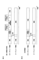
- FIG. 2A is a time chart at the time of operation switching in the first embodiment
- FIG. 2B is a time chart similar to FIG. 2A in the conventional structure.
- FIG. 1 for explaining the path through which the circulating wash water flows.
- It is a graph which shows the relationship between the flow rate of the circulating wash water, and time.
- FIG. 1 of the exhaust gas treatment apparatus which concerns on 1st modification.
- FIG. 1 of the exhaust gas treatment apparatus which concerns on 2nd modification.
- FIG. 1 is a schematic configuration diagram of an exhaust gas treatment device according to the first embodiment.
- the exhaust gas treatment device according to the present embodiment a device for purifying the exhaust gas discharged from the engine used in the ship will be considered.
- the present invention is not limited to this, and the exhaust gas treatment apparatus according to the present embodiment can be applied to the treatment of exhaust gas in a thermal power generation plant, a chemical industry plant, and a waste incinerator.
- the exhaust gas treatment device 1 includes a scrubber 10 into which an exhaust gas g1 is introduced from an engine E through an exhaust gas pipe E1 and a supply path 20 for supplying the exhaust gas cleaning water a1 or the circulating water a2 described later to the scrubber 10. It is provided with a water supply channel 30 that supplies seawater from the sea outside the exhaust gas treatment device 1 as exhaust gas cleaning water a1 to the supply path 20.
- the exhaust gas g1 introduced into the scrubber 10 contains SO 2 (sulfur dioxide) which is a sulfur oxide.
- SO 2 sulfur dioxide
- a boiler may be used instead of the engine E.
- the exhaust gas washing water a1 and the circulating water a2 introduced into the scrubber 10 are sprayed by a plurality of nozzles (not shown) and come into gas-liquid contact with the exhaust gas g1 rising in the scrubber 10. SO 2 in the exhaust gas g1 is absorbed and removed by the exhaust gas washing water a1 and the circulating water a2. Therefore, the exhaust gas g1 becomes the purified gas g2 purified in the scrubber 10, and is exhausted from the upper part of the scrubber 10 into the atmosphere.
- a gas analyzer 11 is installed on the outlet side of the purified gas g2 in the scrubber 10.
- the gas analyzer 11 is configured by a laser type gas analyzer or the like, and the SO 2 concentration of the purified gas g2 that has passed through the scrubber 10 is measured.
- the exhaust gas washing water a1 and the circulating water a2 that have absorbed SO 2 become drainage a3, fall along the inner wall surface of the scrubber 10 by their own weight, and are stored below.
- the supply path 20 includes branch pipes 21 that are branched into a plurality of branches before being introduced into the scrubber 10, and valves 22 are provided in each of the branch pipes 21.
- the supply path 20 is provided so that the flow rate of the exhaust gas cleaning water a1 or the like to the scrubber 10 can be adjusted through the opening and closing of the valves 22 in the plurality of branch pipes 21.
- a flow meter 23 is provided on the upstream side of the branch position of the branch pipe 21 in the supply path 20.
- the flow meter 23 is composed of a mass flow meter or the like, and is provided so as to be able to measure and output the flow rates of the exhaust gas washing water a1 and the circulating water a2 flowing through the supply path 20.
- a valve 31 is provided between the supply channel 20 and the water supply channel 30.
- the downstream side of the valve 31 is the supply passage 20, and the upstream side is the water supply passage 30.
- the valve 31 makes it possible to switch between supplying and stopping the exhaust gas washing water a1 from the water supply channel 30 to the supply channel 20.
- the water supply channel 30 is provided with a branch pipe 32 branched on the upstream side, and a seawater pump 33 is provided in each of the branch pipes 32.
- the water supply channel 30 is provided so that the flow rate of the exhaust gas washing water a1 supplied through the operation of the seawater pump 33 in the plurality of branch pipes 32 can be adjusted.
- a cooling pipe 35 is branched on the upstream side of the valve 31 in the water supply channel 30, and the cooling pipe 35 supplies the heat exchanger 36 with the exhaust gas cleaning water a1 which becomes seawater.
- the exhaust gas cleaning water a1 supplied is used as cooling water and then discharged to the sea.
- a valve 37 capable of adjusting the flow rate of the exhaust gas washing water a1 is provided on the upstream side of the heat exchanger 36 of the cooling pipe 35.
- the exhaust gas treatment device 1 includes a discharge path 40 and an introduction path 50 into which the wastewater a3 from the scrubber 10 is introduced, a wastewater treatment device 60 provided on the downstream side of the introduction path 50, a wastewater treatment device 60, and a supply path 20. It is further provided with a circulation path 70 for connecting the above.
- the discharge path 40 and the introduction path 50 are branched and provided near the outlet for the drainage a3 of the scrubber 10.
- a valve 41 is provided on the upstream side of the discharge path 40, and the introduction and stop of the drainage a3 into the discharge path 40 can be switched by opening and closing the valve 41.
- a valve 51 is also provided on the upstream side of the introduction path 50, and the introduction and stop of the drainage a3 into the introduction path 50 can be switched by opening and closing the valve 51.
- the discharge destination of the drainage a3 is selected as the discharge path 40.
- the discharge destination of the drainage a3 can be switched to either the discharge path 40 or the introduction path 50 by the two valves 41 and 51, and the flow of the drainage a3 to the outside of the device in the discharge path 40 can be switched.
- the second switching portion is configured by the two valves 41 and 51.
- the discharge channel 40 is provided to discharge the wastewater a3 to the sea outside the exhaust gas treatment device 1. Specifically, the discharge path 40 stores the drainage a3 of the scrubber 10 in the gas seal chamber 42 and then discharges it to the sea. The pH value or the like of the drainage a3 stored in the gas seal chamber 42 is measured by the water quality meter 43.
- the introduction path 50 introduces the wastewater a3 from the scrubber 10 into the buffer tank 61 of the wastewater treatment device 60.
- the circulation washing water supply unit 53, the detergent supply unit 54, and the alkaline chemical supply unit 55 are connected to the introduction path 50.
- the circulating washing water supply unit 53 is provided so as to be able to supply the circulating washing water a4 (see FIG. 3) which becomes seawater or fresh water in the introduction path 50.
- the circulating washing water supply unit 53 connects a pipe branched from the water supply channel 30 to the introduction path 50, or provides a pump in a path independent of the water supply path 30 to provide an introduction path.
- supplying seawater to 50 can be exemplified.
- the circulating wash water supply unit 53 may be provided with a tank for storing seawater or fresh water in the ship, and seawater or fresh water may be supplied from the tank to the introduction path 50.
- the detergent supply unit 54 is provided so that a component that easily dissolves and removes coagulated by-products and soot in the introduction path 50, the circulation path 70, etc., such as hydrochloric acid, can be supplied to the introduction path 50 as a detergent.
- a pump 57 is provided in the pipe connecting the detergent supply unit 54 and the introduction path 50, and the amount of detergent supplied is adjusted by controlling the drive of the pump 57.
- the alkaline chemical supply unit 55 is provided so that the alkaline chemical can be supplied to the introduction path 50.
- the alkaline chemicals include an aqueous NaOH solution diluted to a predetermined concentration, an Mg (OH) 2 slurry solution, a Ca (OH) 2 slurry solution, and a CaCO 3 slurry solution, and these may be used alone. , A mixture of a plurality of combinations may be used.
- a pump 58 is provided in the pipe connecting the alkaline chemical supply unit 55 and the introduction path 50, and the supply amount of the alkaline chemical is adjusted by controlling the drive of the pump 58.
- the wastewater treatment device 60 includes a buffer tank 61, a water treatment device 62, and a pipe 65 for sending wastewater a3 from the buffer tank 61 to the water treatment device 62 via a pump 64.
- the water treatment device 62 performs a treatment for improving the water quality by removing soot contained in the wastewater a3 as a predetermined treatment.
- the sludge collected as agglomerates or the like after being treated by the water treatment device 62 is stored in the sludge tank 66.
- the wastewater a3 treated by the water treatment device 62 is supplied as circulating water a2 from the pipe 67 to the circulation path 70 via the buffer tank 61.
- a pipe 68 that branches from the middle of the pipe 67 and is connected to the discharge path 40 is provided, and the waste water a3 treated by the water treatment device 62 is not returned to the buffer tank 61 but goes to the sea via the gas seal chamber 42. Can be released.
- a valve 69 is provided on the upstream side of the pipe 68, and the supply and stop of the treated wastewater a3 to the gas seal chamber 42 can be switched by opening and closing the valve 69.
- the circulation path 70 is connected to the buffer tank 61 on the upstream side, passes through the heat exchanger 36 on the downstream side, and is connected to the vicinity of the valve 31 in the supply path 20.
- the circulation path 70 includes a plurality of parallel pipes 71 (two in the present embodiment) that branch at an intermediate position and then merge. Further, the circulation path 70 further includes a circulation pump 72 and a valve 73 provided in each of the parallel pipes 71.
- the circulating water a2 flowing through the circulation path 70 is cooled by passing through the heat exchanger 36.
- a valve 75 is provided on the downstream side of the circulation path 70, and the supply and stop of the circulating water a2 from the circulation path 70 to the supply path 20 can be switched by opening and closing the valve 75.
- the circulation water a2 is supplied from the circulation passage 70 to the supply passage 20.
- the exhaust gas washing water a1 is supplied from the water supply passage 30 to the supply passage 20. Therefore, the supply of the exhaust gas washing water a1 from the water supply channel 30 and the supply of the circulating water a2 from the circulation path 70 can be switched to the supply path 20 by the two valves 31 and 75.
- the first switching portion is configured by the two valves 31 and 75.
- the exhaust gas treatment device 1 further includes a bypass path 80 that communicates between the valve 51 on the upstream side of the valve 75 in the circulation path 70 and the valve 51 on the upstream side of the introduction path 50 and the circulation washing water supply unit 53.
- the bypass path 80 includes a plurality of parallel pipes 81 (three in the present embodiment) that branch at an intermediate position and then merge. Further, the bypass path 80 further includes a valve 83 provided in each parallel pipe 81.
- the exhaust gas treatment device 1 includes a control device 90.
- the control device 90 is, for example, by a programmable controller (PLC) including a processor that executes various processes necessary for controlling a plurality of operations, which will be described later, and a storage medium such as a ROM (Read Only Memory) and a RAM (Random Access Memory). It is composed.
- the control device 90 includes valves 22, 31, 37, 41, 51, 69, 73, 75, 83, pumps 33, 57, 58, 64, 72, a gas analyzer 11, a flow meter 23, a water quality meter 43, and the like. It is connected to the engine E via a predetermined signal line (shown by a broken line).
- the control device 90 performs open / close control of each valve 22, 31, 37, 41, 51, 69, 73, 75, 83 and drive control of each pump 33, 57, 58, 64, 72.
- the exhaust gas treatment device 1 in the present embodiment is a hybrid type capable of switching between so-called open loop operation and closed loop operation.
- the open loop operation the exhaust gas washing water a1 is pumped from the sea and sprayed in the scrubber 10, and the wastewater a3 used for desulfurization of the exhaust gas g1 is discharged into the sea in the scrubber 10.
- the closed loop operation the wastewater a3 used for desulfurization of the exhaust gas g1 is predeterminedly treated to form circulating water a2, which is repeatedly used for desulfurization with the scrubber 10.
- the valves 22, 31, and 41 are opened, the valves 51 and 75 are closed, and the seawater pump 33 is driven through the control by the control device 90.
- the exhaust gas washing water a1 is supplied from the water supply channel 30 to the supply channel 20.
- the exhaust gas cleaning water a1 is introduced into the scrubber 10 via the branch pipe 21 of the supply path 20, and the introduced exhaust gas cleaning water a1 is sprayed into the scrubber 10 by a plurality of nozzles (not shown).
- the exhaust gas cleaning water a1 is brought into gas-liquid contact with the exhaust gas g1 rising in the scrubber 10, and SO 2 in the exhaust gas g1 is absorbed and purified by the exhaust gas cleaning water a1.
- the exhaust gas washing water a1 that has absorbed SO 2 is treated as drainage a3 and is stored below the scrubber 10. Then, the drainage a3 in the scrubber 10 is discharged to the sea through the discharge passage 40.
- valves 22, 51, 73, 75 are opened, valves 31, 41, 69, 83 are closed, and pumps 64, 72 are driven.
- the supply of the exhaust gas washing water a1 to the supply channel 20 is stopped from the water supply channel 30, and the circulating water a2 is supplied from the circulation path 70.
- the introduction of the drainage a3 from the scrubber 10 to the discharge path 40 is stopped, and the drainage a3 is introduced into the introduction path 50.
- Alkaline chemicals are supplied from the alkaline chemical supply unit 55 to the drainage a3 introduced into the introduction path 50 by driving the pump 58 as needed, and the neutralization reaction is performed in the drainage a3.
- the wastewater a3 that has passed through the introduction path 50 is stored in the buffer tank 61 of the wastewater treatment device 60, and after the water quality is improved via the water treatment device 62, it flows through the circulation path 70 as circulating water a2 through the buffer tank 61.
- the circulation path 70 the circulating water a2 is sent out by driving the circulation pump 72, and the circulating water a2 is cooled through the heat exchanger 36 and then supplied to the supply path 20 through the valve 75.
- the circulating water a2 supplied to the supply path 20 is used for purifying the exhaust gas g1 in the scrubber 10 in the same manner as the exhaust gas washing water a1 in the open loop operation, and then is introduced again into the introduction path 50. Therefore, the circulating water a2 flows in the order of the circulation path 70, the supply path 20, the scrubber 10, the introduction path 50, and the wastewater treatment device 60, and flows through a closed path returning to the circulation path 70 to purify the exhaust gas g1 and improve the water quality. It is used repeatedly and circulated.
- valve 69 When switching from closed loop operation to open loop operation, the valve 69 is opened. As a result, the circulating water a2 used in the closed loop operation is discharged to the sea through the pipe 68 and the discharge path 40.
- FIG. 2A is a time chart at the time of operation switching in the first embodiment.
- FIG. 2B is a time chart similar to FIG. 2A in the conventional structure.
- the discharge of the circulating water a2 used in the closed loop operation and the start (restart) of the open loop operation are carried out at substantially the same timing. Due to the discharge of the circulating water a2, the circulating water a2 is emptied in each of the pipes and devices except the supply path 20 and the scrubber 10 in the above-mentioned route through which the circulating water a2 flows.
- the valves 31 and 41 are opened, the valves 51 and 75 are closed, and the seawater pump 33 is driven.
- FIG. 3 is a configuration diagram similar to FIG. 1 for explaining the flow path of the circulating wash water.
- the circulating washing water a4 is supplied from the circulating washing water supply unit 53 as shown in FIG.
- the valve 75 on the downstream side of the circulation path 70 and the valve 51 on the upstream side of the introduction path 50 are closed, and the valve 73 of the circulation path 70 and the valve 83 of the bypass path 80 are opened.
- the circulating washing water a4 flowing in the order of the introduction path 50, the wastewater treatment device 60, and the circulation path 70 flows into the bypass path 80 and returns to the introduction path 50. Is formed.
- the wash circulation operation (wash mode) is carried out.
- the circulation wash water a4 is pumped by the circulation pump 72, and the circulation wash water a4 is circulated through the closed path shown in FIG. Since the circulating wash water a4 is different from the circulating water a2 used in the closed loop operation and is not used for desulfurization of the scrubber 10, the closed path through which the circulating wash water a4 circulates is washed by the circulation. It will be.
- the water quality of the circulating washing water a4 is improved by the wastewater treatment device 60 in the same manner as the above-mentioned wastewater a3. Further, in the washing circulation operation, the detergent is supplied from the detergent supply unit 54 in the introduction path 50, and the effect of dissolving and removing the by-products and soot coagulated by the circulating washing water a4 containing the detergent can be enhanced.
- FIG. 4 is a graph showing the relationship between the flow rate of circulating wash water and time.
- the flow rate of the circulating washing water a4 is compared with the flow rate of the normal closed loop operation, and the large flow rate and the small flow rate are controlled to be a pulsating flow rate alternately set. It is good to do it.
- By circulating the circulating washing water a4 as the pulsating flow rate in this way it is possible to add a variable water pressure to the coagulated by-products and soot, and it is possible to enhance the effect of dissolving and removing them.
- the flow rate control of the circulating wash water a4 in the washing circulation operation including the control using the circulating washing water a4 as the pulsating flow rate is performed by the control device 90.
- the control device 90 adjusts the opening degree of the valves 73 and 83 by changing the opening degree in a predetermined cycle to adjust the pulsating flow rate. Can be formed. Further, since two valves 73 are connected in parallel in the circulation path 70 and three valves 83 are connected in parallel in the bypass path 80, the control device 90 controls the number of drives of the valves 73 and 83 connected in parallel. Can form a pulsating flow rate. Further, when the circulation pump 72 is equipped with an inverter, the control device 90 can form a pulsating flow rate by controlling the rotation speed (output) of the circulation pump 72.
- the circulating washing water a4 is discharged from the closed path through which the circulating washing water a4 was circulated (see FIG. 2A).
- the valve 69 is opened, and the circulating washing water a4 used in the washing and circulating operation is discharged to the sea through the pipe 68 and the discharge path 40.
- the components such as the introduction path 50, the wastewater treatment device 60, and the circulation path 70, which are used only for the closed loop operation, are put into a standby state while the open loop operation is continued.
- a closed path (see FIG. 3) is formed by the bypass path 80, the introduction path 50, the wastewater treatment device 60, and the circulation path 70. can do.
- the circulating washing water a4 can be flowed through the closed path for washing.
- the circulating water used in the closed loop operation contains high concentrations of by-products (sulfate ions, sodium or magnesium ions caused by alkaline chemicals, etc.) and soot particles due to desulfurization with scrubber. Therefore, when the circulating water is drained from the components of the closed path used for closed-loop operation, the circulating water that remains slightly inside evaporates, and by-products and soot are deposited to precipitate the inner walls of the components such as pipes. It becomes easy to solidify.
- by-products sulfate ions, sodium or magnesium ions caused by alkaline chemicals, etc.
- the open loop operation has a longer operating time than the closed loop operation, the binding force of coagulated by-products and soot becomes stronger and it becomes difficult to remove them. If this is repeated, by-products and soot are clogged inside the components such as pipes, which causes problems such as a decrease in the flow rate of circulating water and an increase in pump energy in the closed loop operation.
- Components such as 70 can be washed.
- FIG. 5 is a schematic configuration diagram of the exhaust gas treatment device according to the second embodiment.
- the discharge passage 40 is omitted, and the pipe (discharge passage) 101 for discharging to the sea in the wastewater treatment device 60 is a buffer as compared with the first embodiment. It is provided connected to the tank 61.
- a valve 102 is provided on the upstream side of the pipe 101, and by opening and closing the valve 102, it is possible to switch between discharging the treated wastewater a3 to the sea (outside the device) and stopping the discharge.
- the valve 102 constitutes the second switching portion.
- the pH value and the like are measured by the water quality meter 103 with respect to the wastewater a3 stored in the buffer tank 61.
- the drainage a3 can be discharged to the sea via the buffer tank 61 and the pipe 101.
- the closed loop operation and the washing circulation operation can be carried out in the same manner as in the first embodiment. Thereby, even in the second embodiment, it is possible to prevent coagulated by-products and soot from remaining in the constituents such as the circulation path 70 used only for the closed loop operation.
- the embodiment of the present invention is not limited to the above embodiment, and may be variously modified, replaced, or modified without departing from the spirit of the technical idea of the present invention. Further, if the technical idea of the present invention can be realized in another way by the advancement of the technology or another technology derived from the technology, it may be carried out by the method. Therefore, the scope of claims covers all embodiments that may be included within the scope of the technical idea of the present invention.
- the first switching unit is composed of two valves 31 and 75, and in the first embodiment, the second switching unit is composed of two valves 41 and 51. , You may change to a three-way valve instead.
- the number of installations of the parallel pipe 71, the circulation pump 72 and the valve 73 in the circulation path 70, and the parallel pipe 81 and the valve 83 in the bypass path 80 may be increased or decreased as long as the above-mentioned pulsating flow rate can be formed.
- the circulation cleaning water supply unit 53 and the detergent supply unit 54 can wash the circulation path 70 or the like by using either the circulation cleaning water a4 or the detergent, the circulation cleaning water supply unit supplies the other.
- the unit 53 and the detergent supply unit 54 may be omitted.
- FIG. 6 is a configuration diagram similar to that of FIG. 3 of the exhaust gas treatment device according to the first modification.
- the water level gauge 111 and the water quality measuring unit 112 are provided in the buffer tank 61 of the wastewater treatment device 60.
- the water level gauge 111 measures the water level of the circulating wash water a4 stored in the buffer tank 61 and outputs the water level to the control device 90.
- the water quality measuring unit 112 measures the water quality (turbidity, pH, PAH, etc.) of the circulating washing water a4 stored in the buffer tank 61 and outputs the water quality to the control device 90.
- a turbidity meter or MLSS meter which is an instrument for measuring turbidity
- a PAH meter for measuring dirt caused by oil, as well as dirt derived from MgO, soot, etc. in the circulating washing water a4 can be used. It can be exemplified, and it is more preferable to measure by sharing both of them.
- the circulating washing water a4 is supplied from the circulating washing water supply unit 53 to the closed path including the introduction path 50, the wastewater treatment device 60, the circulation path 70 and the bypass path 80.
- the water level in the buffer tank 61 of a4 is measured by the water level gauge 111.
- the measurement result of the water level gauge 111 is output to the control device 90.
- the control device 90 controls to stop the supply of the circulating washing water a4 from the circulating washing water supply unit 53 at the timing when the water level of the buffer tank 61 satisfies a predetermined condition required for the washing circulation operation based on the measurement result of the water level gauge 111. I do.
- the control device 90 controls the circulation pump 72 to pump the circulating washing water a4 through a closed route to circulate the water.
- the closed path is washed by the circulation of the circulating washing water a4.
- the water quality of the circulating washing water a4 is improved by the wastewater treatment device 60, and the water quality of the circulating washing water a4 in the buffer tank 61 is measured by the water quality measuring unit 112.
- the measurement result of the circulating wash water a4 by the water quality measuring unit 112 is output to the control device 90.
- the control device 90 controls the circulation of the circulating wash water a4 in the closed path via the drive control of the circulation pump 72 based on the measurement result of the water quality measuring unit 112. For example, if the turbidity of the circulating wash water a4 measured by the water quality measuring unit 112 is equal to or higher than a predetermined drainage reference value, the control device 90 continues to drive the circulation pump 72 and continues to circulate the circulating wash water a4. Take control. Further, the control device 90 controls to stop the drive of the circulation pump 72 at the timing when the turbidity of the circulating wash water a4 becomes less than the predetermined drainage reference value, and stop the circulation of the circulating wash water a4. As a result, the washing circulation operation is completed, and the circulating washing water a4 is discharged from the closed path in which the circulating washing water a4 was circulated according to the completion.
- control device 90 controls the circulation of the circulating wash water a4 and its stop by the drive control of the circulation pump 72 based on the measurement result of the water quality measuring unit 112, but the present invention is not limited to this.
- the output of the circulation pump 72 may be changed to optimize the drive of the circulation pump 72 according to the measurement result of the water quality measuring unit 112.
- the circulating pump 72 is stopped manually by the operator instead of being controlled by the control device 90 to make the circulating wash water a4. You may stop the circulation of.
- the circulation of the circulating wash water a4 in the closed path of the control device 90 can be controlled based on the measurement result of the water quality measuring unit 112.
- the operation of the circulation pump 72 can be optimized according to the degree of cleaning of the closed path by the circulating cleaning water a4, and the circulating cleaning water a4 can be discharged to the sea under the condition that the drainage standard is satisfied.
- the circulating water a2 and the drainage a3 in the closed loop operation may also be measured by the water quality measuring unit 112 or measured by the water level gauge 111 in the same manner as the circulating washing water a4.
- FIG. 7 is a configuration diagram similar to that of FIG. 3 of the exhaust gas treatment device according to the second modification.
- the case where the circulation washing water a4 is supplied from the circulation washing water supply unit 53 to the introduction path 50 is shown in FIG. May be changed as long as it can be supplied.
- the circulating wash water a4 can be supplied.
- the valve 115 is provided on the upstream side of the supply path 20.
- a circulation passage 70 is connected between the valve 115 on the upstream side of the supply passage 20 and the valve 31 between the water supply passage 30 and the supply passage 20.
- a valve 116 is further provided in the circulation path 70.
- a bypass path 80 is communicated between the two valves 75 and 116 in the circulation path 70.
- the valve 116 of the circulation path 70 is provided in the vicinity of the communication position of the bypass path 80 with respect to the circulation path 70.
- the valve 75 on the circulation path 70 is closed while opening the valve 115 on the upstream side of the supply channel 20, so that the seawater from the water supply channel 30 is closed. Is supplied to the supply path 20 as exhaust gas cleaning water a1.
- the seawater (exhaust gas washing water a1) from the water supply path 30 is circulated and washed. It is supplied as water a4 to the bypass path 80 via the circulation path 70.
- the valve 75 of the circulation path 70 is closed and the valve 116 of the circulation path 70 is opened after the supply of the circulation cleaning water a4 is completed and before the start of the cleaning circulation operation.
- the circulating wash water supply unit 53 can be configured by including three valves 75, 115, and 116.
- the circulation washing water supply unit 53 of the second modification can be simply configured by adding two valves 115 and 116 to the first embodiment, and the circulation path 70 used for the closed loop operation. Can be configured using.
- the entire exhaust gas treatment device 1 can be simplified and the device cost can be reduced.
- the valves 115 and 116 are added to the configuration of the first embodiment, but the valves 115 and 116 are similarly added to the configuration of the first modification and the second embodiment. 116 may be added.
- the water quality of the circulating water a2 is improved by the water treatment device 62 in the wastewater treatment device 60 without discharging the circulating water a2 used in the closed loop operation, and the water is circulated in the washing circulation operation. It may be circulated as wash water a4.
- "discharge of circulating water” and "supply of circulating washing water” in the time chart of FIG. 2A can be omitted, and the time before the washing and circulating operation can be shortened.
- the washing circulation operation and the processes before and after the washing circulation operation are carried out during the execution of the open loop operation, but the present invention is not limited to this.
- the washing circulation operation and the processes before and after the washing circulation operation may be performed with both the closed loop operation and the open loop operation stopped.
Landscapes
- Engineering & Computer Science (AREA)
- Chemical & Material Sciences (AREA)
- Chemical Kinetics & Catalysis (AREA)
- Oil, Petroleum & Natural Gas (AREA)
- General Chemical & Material Sciences (AREA)
- Analytical Chemistry (AREA)
- Environmental & Geological Engineering (AREA)
- Health & Medical Sciences (AREA)
- Biomedical Technology (AREA)
- Combustion & Propulsion (AREA)
- General Engineering & Computer Science (AREA)
- Mechanical Engineering (AREA)
- Life Sciences & Earth Sciences (AREA)
- Sustainable Development (AREA)
- Toxicology (AREA)
- Ocean & Marine Engineering (AREA)
- Inorganic Chemistry (AREA)
- Hydrology & Water Resources (AREA)
- Water Supply & Treatment (AREA)
- Organic Chemistry (AREA)
- Treating Waste Gases (AREA)
Abstract
Description
次に、本発明の第2の実施の形態について説明する。なお、以下の説明において、第1の実施の形態と同一若しくは同等の構成部分については同一符号を用いる場合があり、説明を省略若しくは簡略にする場合がある。 [Second Embodiment]
Next, a second embodiment of the present invention will be described. In the following description, the same reference numerals may be used for the same or equivalent components as those in the first embodiment, and the description may be omitted or simplified.
Claims (12)
- 排ガス中に含まれる硫黄酸化物を排ガス洗浄水と接触させ、排ガスを浄化して浄化ガスにし、硫黄酸化物を吸収した前記排ガス洗浄水を排水とするスクラバと、
前記スクラバに前記排ガス洗浄水を供給する供給路と、
前記供給路に装置外部から前記排ガス洗浄水を供給する給水路と、
前記スクラバからの前記排水が導入される導入路と、
前記導入路からの前記排水を所定処理する排水処理装置と、
前記排水処理装置で処理された前記排水を循環水として前記供給路に供給する循環路と、
前記排水を装置外部へ排出するための排出路と、
前記供給路に対し、前記給水路からの前記排ガス洗浄水の供給と前記循環路からの前記循環水の供給とを切り替える第1切替部と、
前記排出路における前記排水の装置外部への流れを切り替える第2切替部とを備え、
前記循環路における前記第1切替部より上流側と、前記導入路の上流側とに連通されて循環洗浄水が流れるバイパス路を更に備えていることを特徴とする排ガス処理装置。 A scrubber that makes sulfur oxides contained in exhaust gas come into contact with exhaust gas cleaning water, purifies the exhaust gas to make it a purifying gas, and uses the exhaust gas cleaning water that has absorbed sulfur oxides as wastewater.
A supply path for supplying the exhaust gas washing water to the scrubber,
A water supply channel that supplies the exhaust gas washing water to the supply channel from the outside of the device,
The introduction path into which the drainage from the scrubber is introduced,
A wastewater treatment device that predeterminedly treats the wastewater from the introduction path,
A circulation path for supplying the wastewater treated by the wastewater treatment device as circulating water to the supply channel,
A drainage channel for draining the drainage to the outside of the device,
A first switching unit that switches between the supply of the exhaust gas washing water from the water supply channel and the supply of the circulating water from the circulation channel to the supply channel.
A second switching unit for switching the flow of the drainage to the outside of the device in the discharge path is provided.
An exhaust gas treatment device further comprising a bypass path communicating with the upstream side of the first switching portion in the circulation path and the upstream side of the introduction path to allow circulating cleaning water to flow. - 前記導入路に前記循環洗浄水を供給する循環洗浄水供給部を更に備えていることを特徴とする請求項1に記載の排ガス処理装置。 The exhaust gas treatment apparatus according to claim 1, further comprising a circulating washing water supply unit for supplying the circulating washing water to the introduction path.
- 前記導入路に洗剤を供給する洗剤供給部を更に備えていることを特徴とする請求項1または請求項2に記載の排ガス処理装置。 The exhaust gas treatment apparatus according to claim 1 or 2, further comprising a detergent supply unit for supplying detergent to the introduction path.
- 前記導入路、前記排水処理装置、前記循環路及び前記バイパス路で形成される閉じた経路での前記循環洗浄水の流量を制御する制御装置を備えていることを特徴とする請求項1ないし請求項3のいずれかに記載の排ガス処理装置。 1. Item 6. The exhaust gas treatment apparatus according to any one of Items 3.
- 前記バイパス路及び前記循環路の少なくとも一方は、中途位置にて分岐してから合流する複数の並列配管と、該複数の並列配管それぞれに設けられたバルブとを備え、
前記制御装置は、前記バルブの駆動数を制御して前記循環洗浄水の流量を脈動流量にすることを特徴とする請求項4に記載の排ガス処理装置。 At least one of the bypass path and the circulation path includes a plurality of parallel pipes that branch at an intermediate position and then merge, and valves provided in each of the plurality of parallel pipes.
The exhaust gas treatment device according to claim 4, wherein the control device controls the number of drives of the valve to make the flow rate of the circulating washing water a pulsating flow rate. - 前記バイパス路及び前記循環路の少なくとも一方は、中途位置にバルブを備え、
前記制御装置は、前記バルブの開度を調整して前記循環洗浄水の流量を脈動流量にすることを特徴とする請求項4に記載の排ガス処理装置。 At least one of the bypass path and the circulation path is provided with a valve in the middle position.
The exhaust gas treatment device according to claim 4, wherein the control device adjusts the opening degree of the valve to make the flow rate of the circulating washing water a pulsating flow rate. - 前記バイパス路及び前記循環路の少なくとも一方は、中途位置にインバータを搭載した循環ポンプを備え、
前記制御装置は、前記インバータを介して前記循環ポンプの出力を制御して前記循環洗浄水の流量を脈動流量にすることを特徴とする請求項4ないし請求項6のいずれかに記載の排ガス処理装置。 At least one of the bypass path and the circulation path is provided with a circulation pump equipped with an inverter in the middle position.
The exhaust gas treatment according to any one of claims 4 to 6, wherein the control device controls the output of the circulation pump via the inverter to make the flow rate of the circulating washing water a pulsating flow rate. Device. - 前記閉じた経路での前記循環洗浄水の水質を測定する水質測定部を備え、
前記制御装置は、前記水質測定部の測定結果に基づき前記閉じた経路での前記循環洗浄水の循環を制御することを特徴とする請求項4ないし請求項7のいずれかに記載の排ガス処理装置。 A water quality measuring unit for measuring the water quality of the circulating wash water in the closed route is provided.
The exhaust gas treatment device according to any one of claims 4 to 7, wherein the control device controls the circulation of the circulating washing water in the closed route based on the measurement result of the water quality measuring unit. .. - 前記請求項1ないし請求項8のいずれかに記載の排ガス処理装置の排ガス処理方法であって、
前記第1切替部を介して前記循環路から前記供給路に前記循環水を供給し、前記第2切替部を介して前記排出路における前記排水の装置外部への流れを停止した状態で、前記スクラバにて排ガスを浄化するクローズドループ運転と、
前記クローズドループ運転の実施後、前記バイパス路、前記導入路、前記排水処理装置及び前記循環路にて形成される閉じた経路に前記循環洗浄水を循環させる洗浄循環運転とを実施することを特徴とする排ガス処理装置の排ガス処理方法。 The exhaust gas treatment method for the exhaust gas treatment device according to any one of claims 1 to 8.
The circulating water is supplied from the circulation path to the supply path through the first switching section, and the flow of the drainage in the discharge path to the outside of the device is stopped through the second switching section. Closed-loop operation that purifies exhaust gas with scrubber,
After the closed loop operation is performed, a washing circulation operation is performed in which the circulating washing water is circulated through the bypass path, the introduction path, the wastewater treatment device, and the closed path formed by the circulation path. Exhaust gas treatment method for exhaust gas treatment equipment. - 前記第1切替部を介して前記給水路から前記供給路に前記排ガス洗浄水を供給し、前記第2切替部を介して前記排出路における前記排水を装置外部へ流すことで、前記スクラバにて排ガスを浄化するオープンループ運転を更に含み、前記クローズドループ運転と前記オープンループ運転とを切り替えて実施し、
前記洗浄循環運転は、前記オープンループ運転の実施中に実施されることを特徴とする請求項9に記載の排ガス処理装置の排ガス処理方法。 The exhaust gas washing water is supplied from the water supply channel to the supply path through the first switching section, and the drainage in the discharge channel is flowed to the outside of the device through the second switching section, whereby the scrubber is used. Further including an open loop operation for purifying exhaust gas, the closed loop operation and the open loop operation are switched and carried out.
The exhaust gas treatment method for an exhaust gas treatment device according to claim 9, wherein the washing circulation operation is performed during the execution of the open loop operation. - 前記クローズドループ運転及び前記オープンループ運転を停止した状態で、前記洗浄循環運転を実施することを特徴とする請求項10に記載の排ガス処理装置の排ガス処理方法。 The exhaust gas treatment method of the exhaust gas treatment device according to claim 10, wherein the washing circulation operation is performed with the closed loop operation and the open loop operation stopped.
- 前記洗浄循環運転は、前記クローズドループ運転で用いた前記循環水を前記循環洗浄水として循環させることを特徴とする請求項9ないし請求項11のいずれかに記載の排ガス処理装置の排ガス処理方法。 The exhaust gas treatment method of the exhaust gas treatment apparatus according to any one of claims 9 to 11, wherein the washing circulation operation circulates the circulating water used in the closed loop operation as the circulating washing water.
Priority Applications (4)
| Application Number | Priority Date | Filing Date | Title |
|---|---|---|---|
| EP21863988.8A EP4112154A4 (en) | 2020-09-04 | 2021-07-28 | Exhaust gas treatment apparatus and exhaust gas treatment method for exhaust gas treatment apparatus |
| CN202180025431.1A CN115348889A (en) | 2020-09-04 | 2021-07-28 | Exhaust gas treatment device and exhaust gas treatment method for exhaust gas treatment device |
| KR1020227032983A KR20220137774A (en) | 2020-09-04 | 2021-07-28 | Exhaust gas treatment device and method of treating exhaust gas of the exhaust gas treatment device |
| JP2022546158A JPWO2022049930A1 (en) | 2020-09-04 | 2021-07-28 |
Applications Claiming Priority (2)
| Application Number | Priority Date | Filing Date | Title |
|---|---|---|---|
| JP2020148843 | 2020-09-04 | ||
| JP2020-148843 | 2020-09-04 |
Publications (1)
| Publication Number | Publication Date |
|---|---|
| WO2022049930A1 true WO2022049930A1 (en) | 2022-03-10 |
Family
ID=80491970
Family Applications (1)
| Application Number | Title | Priority Date | Filing Date |
|---|---|---|---|
| PCT/JP2021/027828 WO2022049930A1 (en) | 2020-09-04 | 2021-07-28 | Exhaust gas treatment apparatus and exhaust gas treatment method for exhaust gas treatment apparatus |
Country Status (5)
| Country | Link |
|---|---|
| EP (1) | EP4112154A4 (en) |
| JP (1) | JPWO2022049930A1 (en) |
| KR (1) | KR20220137774A (en) |
| CN (1) | CN115348889A (en) |
| WO (1) | WO2022049930A1 (en) |
Citations (11)
| Publication number | Priority date | Publication date | Assignee | Title |
|---|---|---|---|---|
| JPS5189226A (en) * | 1975-02-03 | 1976-08-04 | ||
| JPS55143596U (en) * | 1979-04-03 | 1980-10-15 | ||
| JPH08252550A (en) * | 1995-03-17 | 1996-10-01 | Hitachi Ltd | Washing method inside of piping |
| JPH10202213A (en) * | 1997-01-27 | 1998-08-04 | Chiyoda Corp | Method for preventing scaling of piping |
| JP2008279320A (en) * | 2007-05-08 | 2008-11-20 | Ses Co Ltd | Piping unit and cleaning method of treatment liquid feed line |
| JP2010188233A (en) * | 2009-02-16 | 2010-09-02 | Techno Ryowa Ltd | Removing system of water-soluble organic compound |
| WO2016010135A1 (en) * | 2014-07-17 | 2016-01-21 | 三菱日立パワーシステムズ株式会社 | Flue gas desulfurization apparatus and method of operating same |
| CN105749722A (en) * | 2016-04-18 | 2016-07-13 | 大连海事大学 | Novel device and novel method for desulfurization washing of marine diesel exhaust |
| JP2019514678A (en) * | 2016-05-11 | 2019-06-06 | ヤラ マリン テクノロジーズ エーエスYara Marine Technologies As | Desulfurization of ship exhaust gas |
| WO2019230641A1 (en) | 2018-06-01 | 2019-12-05 | 三菱日立パワーシステムズ株式会社 | Exhaust gas purification system and operation method for exhaust gas purification system |
| JP2020148843A (en) | 2019-03-12 | 2020-09-17 | キヤノン株式会社 | Imaging device |
Family Cites Families (2)
| Publication number | Priority date | Publication date | Assignee | Title |
|---|---|---|---|---|
| JP6543762B2 (en) * | 2015-09-10 | 2019-07-10 | サムスン・ヘヴィー・インダストリーズ・カンパニー・リミテッド | Contaminant reduction device |
| KR101804314B1 (en) * | 2016-05-09 | 2018-01-10 | 주식회사 파나시아 | Scrubber system for cleaning exhaust gas |
-
2021
- 2021-07-28 WO PCT/JP2021/027828 patent/WO2022049930A1/en unknown
- 2021-07-28 CN CN202180025431.1A patent/CN115348889A/en active Pending
- 2021-07-28 EP EP21863988.8A patent/EP4112154A4/en not_active Withdrawn
- 2021-07-28 JP JP2022546158A patent/JPWO2022049930A1/ja not_active Withdrawn
- 2021-07-28 KR KR1020227032983A patent/KR20220137774A/en not_active Application Discontinuation
Patent Citations (11)
| Publication number | Priority date | Publication date | Assignee | Title |
|---|---|---|---|---|
| JPS5189226A (en) * | 1975-02-03 | 1976-08-04 | ||
| JPS55143596U (en) * | 1979-04-03 | 1980-10-15 | ||
| JPH08252550A (en) * | 1995-03-17 | 1996-10-01 | Hitachi Ltd | Washing method inside of piping |
| JPH10202213A (en) * | 1997-01-27 | 1998-08-04 | Chiyoda Corp | Method for preventing scaling of piping |
| JP2008279320A (en) * | 2007-05-08 | 2008-11-20 | Ses Co Ltd | Piping unit and cleaning method of treatment liquid feed line |
| JP2010188233A (en) * | 2009-02-16 | 2010-09-02 | Techno Ryowa Ltd | Removing system of water-soluble organic compound |
| WO2016010135A1 (en) * | 2014-07-17 | 2016-01-21 | 三菱日立パワーシステムズ株式会社 | Flue gas desulfurization apparatus and method of operating same |
| CN105749722A (en) * | 2016-04-18 | 2016-07-13 | 大连海事大学 | Novel device and novel method for desulfurization washing of marine diesel exhaust |
| JP2019514678A (en) * | 2016-05-11 | 2019-06-06 | ヤラ マリン テクノロジーズ エーエスYara Marine Technologies As | Desulfurization of ship exhaust gas |
| WO2019230641A1 (en) | 2018-06-01 | 2019-12-05 | 三菱日立パワーシステムズ株式会社 | Exhaust gas purification system and operation method for exhaust gas purification system |
| JP2020148843A (en) | 2019-03-12 | 2020-09-17 | キヤノン株式会社 | Imaging device |
Also Published As
| Publication number | Publication date |
|---|---|
| KR20220137774A (en) | 2022-10-12 |
| EP4112154A1 (en) | 2023-01-04 |
| JPWO2022049930A1 (en) | 2022-03-10 |
| EP4112154A4 (en) | 2023-11-08 |
| CN115348889A (en) | 2022-11-15 |
Similar Documents
| Publication | Publication Date | Title |
|---|---|---|
| KR101680990B1 (en) | Combined cleaning system and method for reduction of sox and nox in exhaust gases from a combustion engine | |
| JP5939366B1 (en) | Scrubber seawater amount control device, scrubber seawater amount control method, and alkali amount control device | |
| KR101530499B1 (en) | Scrubber system and method | |
| JP6269844B2 (en) | Exhaust gas treatment device and waste water treatment method of exhaust gas treatment device | |
| JPWO2014119513A1 (en) | Scrubber seawater control device, scrubber seawater control method, alkali control device, and alkali control method | |
| CN104797790A (en) | A system, a use of such a system and a multi system for cleaning exhaust gas | |
| KR101973108B1 (en) | Treatment method of washing water of offshore structure and vessel | |
| JPH09239233A (en) | Method and apparatus for exhaust gas desulfurization and ship carrying the apparatus | |
| KR20140073280A (en) | Exhausy gas purifying apparatus for a ship | |
| WO2022049930A1 (en) | Exhaust gas treatment apparatus and exhaust gas treatment method for exhaust gas treatment apparatus | |
| KR102120777B1 (en) | Marine Scrubber Washwater Supply and Discharge System | |
| KR20140075204A (en) | Exhaust gas scrubber sea water pump development | |
| KR101775118B1 (en) | Method for reducing water and air pollutant | |
| JP6990787B1 (en) | Cleaning wastewater treatment equipment for marine exhaust gas | |
| KR20170031559A (en) | Apparatus for reducing water and air pollutant | |
| CN212091636U (en) | Exhaust cleaning system | |
| KR102139691B1 (en) | Operation Method of exhaust gas treatment equipment for ship | |
| JP4670160B2 (en) | Wet flue gas desulfurization equipment | |
| WO2022034746A1 (en) | Exhaust gas purification device | |
| KR102334645B1 (en) | Apparatus for reducing water and air pollutant | |
| KR20220009640A (en) | Apparatus for reducing water and air pollutant | |
| JPH0961091A (en) | Cleaning equipment of heat exchanger | |
| KR20210058053A (en) | Water Treatment System For a Ship including Exhaust Gas Purification Device | |
| KR20220008978A (en) | Vessel | |
| JP2000061256A (en) | Gypsum separator filtrate vessel for wet stack gas desulfurizing equipment |
Legal Events
| Date | Code | Title | Description |
|---|---|---|---|
| 121 | Ep: the epo has been informed by wipo that ep was designated in this application |
Ref document number: 21863988 Country of ref document: EP Kind code of ref document: A1 |
|
| ENP | Entry into the national phase |
Ref document number: 2022546158 Country of ref document: JP Kind code of ref document: A |
|
| ENP | Entry into the national phase |
Ref document number: 20227032983 Country of ref document: KR Kind code of ref document: A |
|
| ENP | Entry into the national phase |
Ref document number: 2021863988 Country of ref document: EP Effective date: 20220930 |
|
| NENP | Non-entry into the national phase |
Ref country code: DE |