WO2022049914A1 - 再生制御装置 - Google Patents
再生制御装置 Download PDFInfo
- Publication number
- WO2022049914A1 WO2022049914A1 PCT/JP2021/027152 JP2021027152W WO2022049914A1 WO 2022049914 A1 WO2022049914 A1 WO 2022049914A1 JP 2021027152 W JP2021027152 W JP 2021027152W WO 2022049914 A1 WO2022049914 A1 WO 2022049914A1
- Authority
- WO
- WIPO (PCT)
- Prior art keywords
- injection amount
- late post
- post injection
- temperature
- doc
- Prior art date
Links
- 230000008929 regeneration Effects 0.000 title claims abstract description 96
- 238000011069 regeneration method Methods 0.000 title claims abstract description 96
- 238000002347 injection Methods 0.000 claims abstract description 200
- 239000007924 injection Substances 0.000 claims abstract description 200
- 238000002485 combustion reaction Methods 0.000 claims abstract description 25
- 239000003054 catalyst Substances 0.000 claims abstract description 8
- 230000003647 oxidation Effects 0.000 claims abstract description 8
- 238000007254 oxidation reaction Methods 0.000 claims abstract description 8
- 230000010354 integration Effects 0.000 claims description 4
- 239000013618 particulate matter Substances 0.000 abstract description 34
- 230000007775 late Effects 0.000 description 94
- 239000007789 gas Substances 0.000 description 64
- 239000000446 fuel Substances 0.000 description 55
- 238000000034 method Methods 0.000 description 38
- 238000010586 diagram Methods 0.000 description 10
- 238000000746 purification Methods 0.000 description 9
- 239000000779 smoke Substances 0.000 description 9
- 230000007704 transition Effects 0.000 description 9
- 238000002474 experimental method Methods 0.000 description 8
- 238000012545 processing Methods 0.000 description 7
- 230000006399 behavior Effects 0.000 description 6
- 230000000052 comparative effect Effects 0.000 description 6
- 230000014509 gene expression Effects 0.000 description 6
- 238000012937 correction Methods 0.000 description 5
- 238000011144 upstream manufacturing Methods 0.000 description 5
- UGFAIRIUMAVXCW-UHFFFAOYSA-N Carbon monoxide Chemical compound [O+]#[C-] UGFAIRIUMAVXCW-UHFFFAOYSA-N 0.000 description 4
- MWUXSHHQAYIFBG-UHFFFAOYSA-N Nitric oxide Chemical compound O=[N] MWUXSHHQAYIFBG-UHFFFAOYSA-N 0.000 description 4
- 238000009825 accumulation Methods 0.000 description 4
- 229910002091 carbon monoxide Inorganic materials 0.000 description 4
- 238000013329 compounding Methods 0.000 description 4
- 230000006870 function Effects 0.000 description 4
- 230000000630 rising effect Effects 0.000 description 4
- 230000007423 decrease Effects 0.000 description 3
- 238000011068 loading method Methods 0.000 description 3
- 230000002123 temporal effect Effects 0.000 description 3
- 230000002411 adverse Effects 0.000 description 2
- 239000000919 ceramic Substances 0.000 description 2
- 230000008021 deposition Effects 0.000 description 2
- 238000001514 detection method Methods 0.000 description 2
- 238000006073 displacement reaction Methods 0.000 description 2
- 230000000694 effects Effects 0.000 description 2
- 238000001914 filtration Methods 0.000 description 2
- 238000000465 moulding Methods 0.000 description 2
- 230000001590 oxidative effect Effects 0.000 description 2
- MGWGWNFMUOTEHG-UHFFFAOYSA-N 4-(3,5-dimethylphenyl)-1,3-thiazol-2-amine Chemical compound CC1=CC(C)=CC(C=2N=C(N)SC=2)=C1 MGWGWNFMUOTEHG-UHFFFAOYSA-N 0.000 description 1
- 238000012935 Averaging Methods 0.000 description 1
- QVGXLLKOCUKJST-UHFFFAOYSA-N atomic oxygen Chemical compound [O] QVGXLLKOCUKJST-UHFFFAOYSA-N 0.000 description 1
- 238000006243 chemical reaction Methods 0.000 description 1
- 239000000567 combustion gas Substances 0.000 description 1
- 230000001186 cumulative effect Effects 0.000 description 1
- 238000007599 discharging Methods 0.000 description 1
- 239000010419 fine particle Substances 0.000 description 1
- 238000012423 maintenance Methods 0.000 description 1
- 239000000463 material Substances 0.000 description 1
- JCXJVPUVTGWSNB-UHFFFAOYSA-N nitrogen dioxide Inorganic materials O=[N]=O JCXJVPUVTGWSNB-UHFFFAOYSA-N 0.000 description 1
- 231100000989 no adverse effect Toxicity 0.000 description 1
- 238000013021 overheating Methods 0.000 description 1
- 239000001301 oxygen Substances 0.000 description 1
- 229910052760 oxygen Inorganic materials 0.000 description 1
- 238000002360 preparation method Methods 0.000 description 1
- 238000011084 recovery Methods 0.000 description 1
- 230000001172 regenerating effect Effects 0.000 description 1
- 239000004071 soot Substances 0.000 description 1
- 238000012360 testing method Methods 0.000 description 1
- 238000009423 ventilation Methods 0.000 description 1
Images


Classifications
-
- F—MECHANICAL ENGINEERING; LIGHTING; HEATING; WEAPONS; BLASTING
- F01—MACHINES OR ENGINES IN GENERAL; ENGINE PLANTS IN GENERAL; STEAM ENGINES
- F01N—GAS-FLOW SILENCERS OR EXHAUST APPARATUS FOR MACHINES OR ENGINES IN GENERAL; GAS-FLOW SILENCERS OR EXHAUST APPARATUS FOR INTERNAL COMBUSTION ENGINES
- F01N3/00—Exhaust or silencing apparatus having means for purifying, rendering innocuous, or otherwise treating exhaust
- F01N3/02—Exhaust or silencing apparatus having means for purifying, rendering innocuous, or otherwise treating exhaust for cooling, or for removing solid constituents of, exhaust
- F01N3/021—Exhaust or silencing apparatus having means for purifying, rendering innocuous, or otherwise treating exhaust for cooling, or for removing solid constituents of, exhaust by means of filters
- F01N3/033—Exhaust or silencing apparatus having means for purifying, rendering innocuous, or otherwise treating exhaust for cooling, or for removing solid constituents of, exhaust by means of filters in combination with other devices
- F01N3/035—Exhaust or silencing apparatus having means for purifying, rendering innocuous, or otherwise treating exhaust for cooling, or for removing solid constituents of, exhaust by means of filters in combination with other devices with catalytic reactors, e.g. catalysed diesel particulate filters
-
- F—MECHANICAL ENGINEERING; LIGHTING; HEATING; WEAPONS; BLASTING
- F01—MACHINES OR ENGINES IN GENERAL; ENGINE PLANTS IN GENERAL; STEAM ENGINES
- F01N—GAS-FLOW SILENCERS OR EXHAUST APPARATUS FOR MACHINES OR ENGINES IN GENERAL; GAS-FLOW SILENCERS OR EXHAUST APPARATUS FOR INTERNAL COMBUSTION ENGINES
- F01N3/00—Exhaust or silencing apparatus having means for purifying, rendering innocuous, or otherwise treating exhaust
- F01N3/08—Exhaust or silencing apparatus having means for purifying, rendering innocuous, or otherwise treating exhaust for rendering innocuous
- F01N3/10—Exhaust or silencing apparatus having means for purifying, rendering innocuous, or otherwise treating exhaust for rendering innocuous by thermal or catalytic conversion of noxious components of exhaust
- F01N3/103—Oxidation catalysts for HC and CO only
-
- F—MECHANICAL ENGINEERING; LIGHTING; HEATING; WEAPONS; BLASTING
- F01—MACHINES OR ENGINES IN GENERAL; ENGINE PLANTS IN GENERAL; STEAM ENGINES
- F01N—GAS-FLOW SILENCERS OR EXHAUST APPARATUS FOR MACHINES OR ENGINES IN GENERAL; GAS-FLOW SILENCERS OR EXHAUST APPARATUS FOR INTERNAL COMBUSTION ENGINES
- F01N11/00—Monitoring or diagnostic devices for exhaust-gas treatment apparatus, e.g. for catalytic activity
- F01N11/002—Monitoring or diagnostic devices for exhaust-gas treatment apparatus, e.g. for catalytic activity the diagnostic devices measuring or estimating temperature or pressure in, or downstream of the exhaust apparatus
-
- F—MECHANICAL ENGINEERING; LIGHTING; HEATING; WEAPONS; BLASTING
- F01—MACHINES OR ENGINES IN GENERAL; ENGINE PLANTS IN GENERAL; STEAM ENGINES
- F01N—GAS-FLOW SILENCERS OR EXHAUST APPARATUS FOR MACHINES OR ENGINES IN GENERAL; GAS-FLOW SILENCERS OR EXHAUST APPARATUS FOR INTERNAL COMBUSTION ENGINES
- F01N3/00—Exhaust or silencing apparatus having means for purifying, rendering innocuous, or otherwise treating exhaust
- F01N3/02—Exhaust or silencing apparatus having means for purifying, rendering innocuous, or otherwise treating exhaust for cooling, or for removing solid constituents of, exhaust
- F01N3/021—Exhaust or silencing apparatus having means for purifying, rendering innocuous, or otherwise treating exhaust for cooling, or for removing solid constituents of, exhaust by means of filters
- F01N3/023—Exhaust or silencing apparatus having means for purifying, rendering innocuous, or otherwise treating exhaust for cooling, or for removing solid constituents of, exhaust by means of filters using means for regenerating the filters, e.g. by burning trapped particles
- F01N3/025—Exhaust or silencing apparatus having means for purifying, rendering innocuous, or otherwise treating exhaust for cooling, or for removing solid constituents of, exhaust by means of filters using means for regenerating the filters, e.g. by burning trapped particles using fuel burner or by adding fuel to exhaust
- F01N3/0253—Exhaust or silencing apparatus having means for purifying, rendering innocuous, or otherwise treating exhaust for cooling, or for removing solid constituents of, exhaust by means of filters using means for regenerating the filters, e.g. by burning trapped particles using fuel burner or by adding fuel to exhaust adding fuel to exhaust gases
-
- F—MECHANICAL ENGINEERING; LIGHTING; HEATING; WEAPONS; BLASTING
- F01—MACHINES OR ENGINES IN GENERAL; ENGINE PLANTS IN GENERAL; STEAM ENGINES
- F01N—GAS-FLOW SILENCERS OR EXHAUST APPARATUS FOR MACHINES OR ENGINES IN GENERAL; GAS-FLOW SILENCERS OR EXHAUST APPARATUS FOR INTERNAL COMBUSTION ENGINES
- F01N9/00—Electrical control of exhaust gas treating apparatus
- F01N9/002—Electrical control of exhaust gas treating apparatus of filter regeneration, e.g. detection of clogging
-
- F—MECHANICAL ENGINEERING; LIGHTING; HEATING; WEAPONS; BLASTING
- F01—MACHINES OR ENGINES IN GENERAL; ENGINE PLANTS IN GENERAL; STEAM ENGINES
- F01N—GAS-FLOW SILENCERS OR EXHAUST APPARATUS FOR MACHINES OR ENGINES IN GENERAL; GAS-FLOW SILENCERS OR EXHAUST APPARATUS FOR INTERNAL COMBUSTION ENGINES
- F01N2430/00—Influencing exhaust purification, e.g. starting of catalytic reaction, filter regeneration, or the like, by controlling engine operating characteristics
- F01N2430/08—Influencing exhaust purification, e.g. starting of catalytic reaction, filter regeneration, or the like, by controlling engine operating characteristics by modifying ignition or injection timing
-
- F—MECHANICAL ENGINEERING; LIGHTING; HEATING; WEAPONS; BLASTING
- F01—MACHINES OR ENGINES IN GENERAL; ENGINE PLANTS IN GENERAL; STEAM ENGINES
- F01N—GAS-FLOW SILENCERS OR EXHAUST APPARATUS FOR MACHINES OR ENGINES IN GENERAL; GAS-FLOW SILENCERS OR EXHAUST APPARATUS FOR INTERNAL COMBUSTION ENGINES
- F01N2900/00—Details of electrical control or of the monitoring of the exhaust gas treating apparatus
- F01N2900/04—Methods of control or diagnosing
- F01N2900/0408—Methods of control or diagnosing using a feed-back loop
-
- F—MECHANICAL ENGINEERING; LIGHTING; HEATING; WEAPONS; BLASTING
- F01—MACHINES OR ENGINES IN GENERAL; ENGINE PLANTS IN GENERAL; STEAM ENGINES
- F01N—GAS-FLOW SILENCERS OR EXHAUST APPARATUS FOR MACHINES OR ENGINES IN GENERAL; GAS-FLOW SILENCERS OR EXHAUST APPARATUS FOR INTERNAL COMBUSTION ENGINES
- F01N2900/00—Details of electrical control or of the monitoring of the exhaust gas treating apparatus
- F01N2900/06—Parameters used for exhaust control or diagnosing
- F01N2900/16—Parameters used for exhaust control or diagnosing said parameters being related to the exhaust apparatus, e.g. particulate filter or catalyst
- F01N2900/1602—Temperature of exhaust gas apparatus
-
- Y—GENERAL TAGGING OF NEW TECHNOLOGICAL DEVELOPMENTS; GENERAL TAGGING OF CROSS-SECTIONAL TECHNOLOGIES SPANNING OVER SEVERAL SECTIONS OF THE IPC; TECHNICAL SUBJECTS COVERED BY FORMER USPC CROSS-REFERENCE ART COLLECTIONS [XRACs] AND DIGESTS
- Y02—TECHNOLOGIES OR APPLICATIONS FOR MITIGATION OR ADAPTATION AGAINST CLIMATE CHANGE
- Y02T—CLIMATE CHANGE MITIGATION TECHNOLOGIES RELATED TO TRANSPORTATION
- Y02T10/00—Road transport of goods or passengers
- Y02T10/10—Internal combustion engine [ICE] based vehicles
- Y02T10/40—Engine management systems
Definitions
- the present disclosure relates to a regeneration control device for regenerating an exhaust gas treatment device having a DOC and a DPF arranged in an exhaust passage of a diesel engine.
- the diesel engine is equipped with an exhaust gas treatment device consisting of a DOC (diesel oxidation catalyst) arranged in the exhaust passage and a DPF (diesel particulate filter) arranged downstream of the DOC.
- the DPF is a device for collecting PM (particulate matter) contained in the exhaust gas discharged from a diesel engine.
- the DPF is generally configured by molding ceramic or the like into a honeycomb-shaped monolith, and adjacent ventilation holes are alternately closed on the inlet side and the outlet side so that the exhaust gas passes through the filtration wall, and PM is removed by this filtration wall.
- Some DPFs carry a catalyst.
- the DOC is generally formed by molding ceramic or the like into a honeycomb-shaped monolith, and supports an oxidation catalyst on the inner surface thereof.
- the forced regeneration of the DPF is performed by raising the exhaust gas temperature and forcibly raising the temperature of the DPF. For example, this temperature rise is performed by delaying fuel injection timing, post injection, intake or exhaust throttle, and the like.
- the upper limit value of the injection amount is determined only by the air-fuel ratio, and the upper limit value of the injection amount is determined regardless of the DOC temperature.
- the injection amount must be limited so that white smoke is not generated regardless of the DOC temperature. Therefore, the injection amount must be set to be small so that white smoke is not generated at any temperature, and the control is executed so as to excessively suppress the injection amount, and the DPF regeneration time increases. There is a risk.
- the present disclosure realizes fine control so as not to excessively suppress the late post injection amount injected at a timing that does not contribute to in-cylinder combustion, and generates white smoke without increasing the DPF regeneration time.
- the purpose is to reduce.
- the reproduction control device is In an exhaust gas treatment device of a diesel engine provided with a diesel oxidation catalyst (DOC) arranged in an exhaust passage of an internal combustion engine and a diesel particulate filter (DPF) arranged downstream of the DOC, the temperature of the DPF is increased to the DPF.
- the late post injection amount determining unit is configured to determine an upper limit value of the late post injection amount based on the excess air ratio of the exhaust gas flowing into the DOC acquired based on the temperature index of the DOC. ..
- fine control can be realized so as not to excessively suppress the late post injection amount, and the generation of white smoke can be reduced without increasing the DPF regeneration time.
- expressions such as “same”, “equal”, and “homogeneous” that indicate that things are in the same state not only represent exactly the same state, but also have tolerances or differences to the extent that the same function can be obtained. It shall also represent the existing state.
- the expression representing a shape such as a quadrangular shape or a cylindrical shape not only represents a shape such as a quadrangular shape or a cylindrical shape in a geometrically strict sense, but also an uneven portion or a chamfer within the range where the same effect can be obtained. It shall also represent the shape including the part and the like.
- the expressions “equipped”, “equipped”, “equipped”, “included”, or “have” one component are not exclusive expressions excluding the existence of other components.
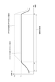
- FIG. 1 is a schematic diagram illustrating an overall configuration of a diesel engine 1 having a regeneration control device 2 according to an embodiment of the present invention.
- the regeneration control device 2 regenerates the exhaust gas treatment device 3 arranged in the exhaust passage 16 of the diesel engine 1 (that is, the recovery process of the DOC 31 and the forced regeneration process of the DPF 32) by the temperature raising means 4 (4A, 4A, of the exhaust gas treatment device 3). It is executed by controlling 4B, 4C, 4D, 4E).
- the diesel engine 1 in addition to the regeneration control device 2 (ECU 9) and the exhaust gas treatment device 3, the diesel engine 1 includes an engine main body 11, an intake passage 13, an exhaust passage 16, and an exhaust turbocharger 7. , EGR device 8 and.
- the reproduction control device 2 is an ECU (Engine Control Unit) 9, and is implemented as one of the functions (programs and circuits) included in the ECU 9.
- the regeneration control device 2 may be configured as another electronic control unit including a processor, in addition to the ECU 9 that controls the diesel engine 1.
- the ECU 9 is an electronic control unit that controls the diesel engine 1.
- the ECU 9 may be configured as a microcomputer including a central processing unit (CPU) including a processor, a random access memory (RAM), a read-only memory (ROM), an I / O interface, and the like.
- CPU central processing unit
- RAM random access memory
- ROM read-only memory
- I / O interface I / O interface
- the intake passage 13 and the exhaust passage 16 are connected to the engine body 11.
- the intake passage 13 is a passage for supplying air (intake) outside the diesel engine 1 to the combustion chamber 12 formed in the engine body 11.
- the exhaust passage 16 is a passage for discharging the combustion gas (exhaust gas) from the combustion chamber 12 to the outside of the diesel engine 1.
- the exhaust passage 16 is provided with an exhaust throttle valve 4 (4C) at a position directly upstream of the DOC 31.
- the opening degree of the exhaust throttle valve 4 (4C) is controlled by the regeneration control device 2 (ECU 9).
- the diesel engine 1 is provided with a fuel injection device 4 (4A) for injecting high-pressure fuel into the combustion chamber 12.
- the fuel injection device 4A is connected to a common rail (not shown) in which high-pressure fuel is stored, and the injection timing and fuel injection amount are controlled by the ECU 9. Then, the high-pressure fuel injected into the combustion chamber 12 is mixed with the intake air supplied through the intake passage 13, then burned in the combustion chamber 12 and discharged to the outside of the diesel engine 1 through the exhaust passage 16. Will be done.
- An exhaust turbocharger 7 is provided in the intake passage 13 and the exhaust passage 16.
- the exhaust turbocharger 7 has an exhaust turbine 41 arranged in the exhaust passage 16 and a compressor 42 arranged in the intake passage 13, and the exhaust turbine 41 and the compressor 42 are connected by a shaft 43. It is coaxially coupled.
- the compressor 42 coaxially coupled by the shaft 43 is also rotationally driven in the same manner.
- the intake passage 13 is provided with an intercooler (not shown) and an intake throttle valve 4 (4B).
- the compressed intake air discharged from the compressor 42 is cooled by an intercooler (not shown), and then the intake flow rate is controlled by the intake throttle valve 4 (4B).
- the main body of the diesel engine 1 cylinder (not shown)). It flows into the combustion chamber 12 in each cylinder of the diesel engine 1 through the intake port 14 provided in the head).
- the opening degree of the intake throttle valve 4 (4B) is also controlled by the regeneration control device 2 (ECU 9).
- the diesel engine 1 is equipped with an EGR device 8. That is, the intake passage 13 and the exhaust passage 16 are connected via the EGR pipe 45, and a part of the exhaust gas flowing through the exhaust passage 16 can be recirculated to the intake passage 13.
- EGR pipe 45 One end of the EGR pipe 45 is connected to a position directly downstream of the exhaust port 17, and the EGR pipe 45 branches from the exhaust passage 16. Further, the other end of the EGR pipe 45 is connected to an intake manifold 15 (intake passage 13) located on the downstream side of the intake throttle valve 4 (4B). Further, an EGR valve 4 (4E) is arranged in the EGR tube 45. By controlling the EGR valve 4 (4E), a part of the exhaust gas discharged from the diesel engine 1 recirculates in the diesel engine 1 through the EGR pipe 45. The opening degree of the EGR valve 4 (4E) is also controlled by the regeneration control device 2 (ECU 9).
- the exhaust gas discharged from the engine body 11 flows into the exhaust gas treatment device 3 provided in the exhaust passage 16 after driving the exhaust turbine 41 described above. It is configured to do.
- the exhaust gas treatment device 3 includes a DOC 31 (diesel oxidation catalyst) arranged in the exhaust passage 16 of the diesel engine 1 and a DPF 32 (diesel particulate filter) arranged in the exhaust passage 16 downstream of the DOC 31.
- the DOC 31 has a function of oxidizing and removing unburned fuel (HC) and carbon monoxide (CO) in the exhaust gas, and oxidizing nitric oxide (NO) in the exhaust gas to generate nitrogen dioxide (NO 2 ). It is a device. Further, in the DOC 31, the temperature of the exhaust gas passing by the heat of oxidation of the fuel injected into the DOC 31 is raised, and the temperature of the inlet of the DPF 32 is raised.
- DPF32 is a device that collects PM (particulate matter) such as soot contained in exhaust gas with a filter and removes it from exhaust gas. That is, the exhaust gas that has flowed into the exhaust gas treatment device 3 passes through the DOC 31 and then the DPF 32 inside the exhaust gas treatment device 3. At the time of this passage, unburned fuel (HC) and carbon monoxide (CO) contained in the exhaust gas are oxidatively removed in the DOC 31. Further, PM (particulate matter) in the exhaust gas is collected by the DPF 32, and PM contained in the exhaust gas is removed. After that, the exhaust gas is discharged to the outside of the diesel engine 1.
- PM partate matter
- the regeneration control device 2 monitors the state of the exhaust gas and the exhaust gas treatment device 3 based on the detected values from various sensors installed in the exhaust passage 16. For example, as shown in FIG. 1, a DOC inlet temperature sensor 5 (5A) is provided at the inlet of the DOC 31, and the exhaust gas temperature flowing into the DOC 31 is detected. A DPF inlet temperature sensor 5 (5B) is provided at the inlet of the DPF 32 (between the DOC 31 and the DPF 32), and a DPF outlet temperature sensor 5 (5C) is provided at the outlet of the DPF 32. Further, a DPF inlet pressure sensor 6 (6A) is provided at the inlet of the DPF 32, and a DPF outlet pressure sensor 6 (6B) is provided at the outlet of the DPF 32.
- the DPF 32 is provided with a DPF differential pressure sensor 6 (6C) for detecting the differential pressure between the inlet and the outlet of the DPF 32.
- the detected values of the temperature sensor 5 and the pressure sensor 6 are input to the regeneration control device 2 and used in the execution of the DOC temperature rise control and the DPF forced regeneration process described later.
- the DOC temperature rise execution unit 21 detects the temperature rise required state of the DOC 31, the DOC temperature rise execution unit 21 controls the temperature rise means 4 to execute the temperature rise for recovering the DOC 31.
- This process is a process of controlling the temperature raising means 4 (described later) so as to raise the temperature of the DOC 31 to the temperature T1 (see FIG. 3).
- the temperature T1 is a temperature at which the DOC 31 is activated, and is set to, for example, 250 ° C.
- the temperature rise process may be a process of executing a two-step temperature rise.
- the DOC31 is raised to a temperature higher than the temperature T1 (for example, a temperature for burning deposits on the upstream end surface of the DOC31 such as 400 ° C.). Keep it warm and maintain that temperature.
- the temperature raising means 4 controlled in the DOC temperature rising control is, for example, a fuel injection device 4A (see FIG. 1) that injects fuel into the combustion chamber 12 of the diesel engine 1. Then, the DOC temperature raising process is executed by changing the timing and the injection amount of the early post injection by the fuel injection device 4 (4A).
- FIG. 2 is a diagram for explaining the forced regeneration process of the DPF executed by the early post injection and the late post injection according to the embodiment.
- the early post injection as shown in FIG. 2, in the step of injecting fuel into the diesel engine 1, a smaller amount of fuel is injected than in the main injection while the pressure in the combustion chamber 12 immediately after injecting the main fuel is still high. This is the first post injection.
- the exhaust gas temperature can be increased.
- the temperature rising means 4 controlled in the DOC temperature rising control is the intake throttle valve 4 (4B) or the common rail pressure controlling means for controlling the common rail pressure for injecting fuel (not). (Fig.) May be used.
- the temperature raising means 4 includes a fuel injection device 4A, an intake throttle valve 4B, a common rail pressure control means (not shown), an exhaust pipe injection device 4D, an exhaust throttle valve 4C, and an EGR valve 4E. It may be at least one of them.
- the regeneration control device 2 further includes a DPF forced regeneration execution unit 22.
- the DPF forced regeneration execution unit 22 is configured to execute a forced regeneration process that controls the temperature raising means 4 so as to raise the temperature of the DPF 32 to the temperature T2.
- the temperature T2 is a temperature higher than the temperature T1, and is set to, for example, a temperature of 600 ° C. or higher.
- FIG. 3 is a time chart showing an example of a temperature change when the regeneration control device 2 according to the embodiment executes a forced regeneration process.
- the forced reproduction process is started at time t1 and continues until time t3.
- Late post injection is performed from time t2 when the DOC inlet temperature reaches the temperature T1 to time t3.
- the temperature of the DOC 31 is acquired based on the detection value of the DOC inlet temperature sensor 5 (5A), and the temperature of the DPF 32 is acquired based on the detection value of the DPF inlet temperature sensor 5 (5B).
- the PM accumulated in the filter of the DPF 32 is forcibly burned and removed by executing the forced regeneration process at an appropriate timing.
- the forced regeneration process is classified into at least two types from the viewpoint of triggering the start of execution. That is, there are at least two types of automatic reproduction, that is, automatic reproduction that is automatically executed and manual reproduction that is executed by a manual operation by an operator or the like.
- the automatic regeneration of the DPF 32 is automatically executed by satisfying the predetermined forced regeneration execution condition (automatic regeneration execution condition) regarding the automatic regeneration regardless of whether the vehicle is running or stopped.
- the automatic regeneration execution conditions are, for example, that the estimated value of the PM accumulation amount in the DPF 32 exceeds the specified value (threshold), the operating time of the diesel engine 1 exceeds the specified time (threshold), and the fuel injection amount of the diesel engine 1. It is a condition that the cumulative value of is exceeding the specified amount (threshold).
- the PM deposition amount in the DPF 32 is estimated, for example, by detecting the differential pressure between the upstream and the downstream of the DPF 32 by the DPF differential pressure sensor 6 (6C).
- the engine speed, fuel injection amount, air flow rate, and DPF temperature are detected, and the map is stored in advance in the regeneration control device 2. It is also possible to estimate the PM emission amount from the diesel engine 1 and the PM regeneration amount due to natural regeneration inside the DPF 32, and to estimate the PM accumulation amount by subtracting the PM regeneration amount from the PM emission amount.
- the manual reproduction of the DPF 32 is executed as a forced reproduction execution condition (manual reproduction execution condition) that the operator or the like operates a button, and is basically executed in a state where the vehicle is stopped. ..
- the manual regeneration of the DPF 32 is executed when the PM is accumulated beyond the automatic regeneration condition.
- the condition for executing manual regeneration is that the estimated value of PM deposition exceeds a specified value larger than that for automatic regeneration.
- the manual regeneration of the DPF 32 may include combustion removal performed by a serviceman who performs maintenance when PM is excessively deposited on the DPF 32.
- forced regeneration is performed over a longer period of time than normal manual regeneration.
- the manual regeneration is controlled so that the regeneration temperature is higher than the automatic regeneration.
- the inlet temperature of the DPF 32 is controlled to be 600 to 610 ° C
- the manual regeneration the inlet temperature of the DPF 32 is controlled to be 620 to 630 ° C.
- the temperature raising means 4 used in the forced regeneration process is a fuel injection device 4A and an exhaust pipe injection device 4D that inject fuel into the combustion chamber 12 of the diesel engine 1.
- the forced regeneration process is performed by early post injection by the fuel injection device 4A, late post injection by the fuel injection device 4A, or exhaust pipe injection by the exhaust pipe injection device 4D arranged in the exhaust passage 16 upstream of the DOC 31. Will be executed.
- Late post injection is the second post injection in which fuel is injected at a timing (near bottom dead center) that does not contribute to combustion in the combustion chamber 12 after early post injection.
- TDC top dead center
- BDC bottom dead center
- the main fuel injection is performed after the top dead center, and then early. Post injection is done.
- the late post injection is performed after the early post injection and before the piston reaches the bottom dead center (BDC) from the top dead center (TDC) side.
- the unburned fuel flows out from the combustion chamber 12 to the exhaust passage 16, and the discharged unburned fuel is oxidized in the DOC 31 to raise the temperature of the DPF 32 to the temperature T2. Further, by raising the temperature of the DPF 32 to the temperature T2, the PM deposited on the DPF 32 can be burned.
- the exhaust pipe injection device 4D is arranged between the downstream of the branch position of the EGR pipe 45 and the exhaust turbine 41 of the exhaust turbocharger 7. In some other embodiments, the exhaust pipe injection device 4D may be located between the exhaust turbine 41 and the DOC 31. Further, the fuel injection amount injected from the exhaust pipe injection device 4D to the exhaust passage 16 is controlled by the regeneration control device 2.
- the forced regeneration process of the DPF 32 may be executed after the temperature rise control of the DOC 31 is completed. Further, in some other embodiments, as shown in FIG. 3, the forced regeneration process of the DPF 32 may be executed at a timing independent of the temperature rise control of the DOC 31.
- the temperature of DPF32 is raised to the temperature T1 or higher to activate DPF32.
- This temperature rise may be performed by early post injection under predetermined injection conditions, using the fuel injection device 4A as the temperature raising means 4.
- the intake throttle valve 4B may be used as the temperature raising means 4, and the temperature rise may be executed by controlling the opening degree thereof.
- the common rail pressure control means (not shown) for controlling the common rail pressure for injecting fuel may be used as the temperature raising means 4, and the temperature rise may be executed by controlling the common rail pressure.
- This temperature rise may be performed by using two or more of the fuel injection device 4A, the intake throttle valve 4B, and the common rail pressure control means (not shown) as the temperature raising means 4.
- the temperature of the DPF 32 is raised to the temperature T2 by executing the forced regeneration process of the DPF 32 using the late post injection or the exhaust pipe injection.
- the forced regeneration process of the DPF 32 can be executed by the fuel injection device 4A and the exhaust pipe injection device 4D. Further, when the temperature raising means 4 in the temperature rising control of the DOC 31 is the fuel injection device 4A, the fuel injection device 4A can easily execute the temperature rise control and the forced regeneration process. Further, the fuel injection device 4A is usually provided in the diesel engine 1, and it is not necessary to add another temperature raising means 4, so that the cost can be reduced.
- the DPF forced regeneration execution unit 22 executes the forced regeneration process (automatic regeneration) when it is determined that the forced regeneration execution condition is satisfied, or notifies that the execution of the forced regeneration process is urged, and based on the operator's instruction. Execute forced regeneration processing (manual regeneration).
- the reproduction control device 2 further includes a storage unit 25.
- the storage unit 25 may be a non-volatile memory such as a ROM or a flash memory included in the reproduction control device 2, a volatile memory such as a RAM, or an external storage device connected to the reproduction control device 2. good.
- the storage unit 25 may store information indicating the correspondence between the temperature index of the DOC 31 and the excess air ratio and various maps.
- the reproduction control device 2 further includes a late post injection amount determining unit 23 for determining the late post injection amount.
- FIG. 4 is a block diagram schematically showing the configuration of the late post injection amount determining unit 23 according to the embodiment. Hereinafter, the configuration of the late post injection amount determination unit 23 will be described.
- the late post injection amount determination unit 23 determines the late post injection amount (operation amount) so that the inlet temperature of the DPF 32 becomes the target temperature of about 600 ° C. in the forced regeneration process. As shown in FIG. 4, the late post injection amount determination unit 23 is configured to output a feedforward control unit 47 configured to output a feedforward control command value 57 and a feedback control command value 65. It includes a feedback control unit 49 and an adder 51 configured to add a basic injection amount (feedforward control command value 57) and a correction injection amount (feedback control command value 65). Further, the late post injection amount determination unit 23 includes a reset unit 55 that resets the integrated value of the integrator 53 constituting the feedback control unit 49.
- the feedforward control unit 47 is configured to determine a basic injection amount (basic operation amount) of the late post injection amount based on the operating conditions of the internal combustion engine and output it as a feedforward control command value 57.
- the operating conditions of the internal combustion engine are, for example, the temperature difference between the target inlet temperature of the DPF 32 and the inlet temperature of the DOC 31, and the exhaust gas flow rate.
- the feed forward control unit 47 has a purification rate acquisition unit 85 configured to acquire an HC purification rate based on the DOC average temperature and the exhaust gas flow rate, and a temperature difference between the target inlet temperature of the DPF 32 and the inlet temperature of the DOC 31.
- the gas oil amount acquisition unit 87 configured to acquire the required gas oil amount based on the exhaust gas flow rate.
- the purification rate acquisition unit 85 acquires the HC purification rate by using, for example, the HC purification rate map stored in the storage unit 25.
- the gas oil amount acquisition unit 87 acquires the required gas oil amount by using, for example, the gas oil amount map stored in the storage unit 25.
- the feedforward control unit 47 includes a divider 89 in which the HC purification rate acquired by the purification rate acquisition unit 85 and the required gas oil amount acquired by the light oil amount acquisition unit 87 are input.
- the feedforward control unit 47 outputs the required gas oil amount (that is, the feedforward control command value 57) including the HC purification rate via the divider 89.
- the feedback control unit 49 is configured to determine the late post correction injection amount (correction operation amount) with respect to the target temperature of the DPF 32 and output it as the feedback control command value 65.
- the feedback control unit 49 is provided with a target temperature setting unit 59 for setting a target temperature as an initial value at the start of control of the target inlet temperature of the DPF 32 and a target temperature thereafter.
- the target inlet temperature of the DPF 32 and the actually measured inlet temperature of the DPF 32 are input to the adder / subtractor 61, and the deviation between the target inlet temperature and the actually measured inlet temperature is obtained as an output signal of the adder / subtractor 61.
- This output signal is feedback-calculated by the PID calculation unit 63, and the correction injection amount which is the feedback control command value 65 is calculated. In this way, the feedback control unit 49 determines the corrected injection amount of the late post injection amount based on the deviation between the inlet temperature of the DPF 32 and the target temperature.
- the calculation of the proportional element (P) is performed using the proportional gain Kp
- the calculation of the differential element (D) is performed using the differential gain Kd
- the calculation of the integral element (I) is performed by the integral gain. Ki is performed, each calculation result is input to the adder 67, and the feedback control command value 65 is calculated.
- the feedforward control command value 57 and the feedback control command value 65 are input to the adder 51, and the addition command value 69 is output.
- the signal of the addition command value 69 is input to the command saturation unit 71, and the output signal is restricted for the protection of the DPF 32.
- the signal that has passed through the command saturation section 71 is output as a late post fuel injection command signal via the limiting section 81.
- the limiting unit 81 of the late post injection amount determining unit 23 outputs a late post fuel injection command signal that limits the late post injection amount so that it does not exceed the upper limit of the late post injection amount. For example, when the added value of the basic injection amount and the corrected injection amount is equal to or less than the upper limit of the late post injection amount, the late post injection amount determining unit 23 lates the added value of the basic injection amount and the corrected injection amount. It is determined as the post injection amount, and when the added value of the basic injection amount and the corrected injection amount exceeds the upper limit value of the late post injection amount, the late post injection amount is limited to the upper limit value of the late post injection amount.
- the limiting unit 81 is configured to calculate the upper limit of the late post injection amount.
- the limiting unit 81 of the late post injection amount determining unit 23 integrates the integrator 53 of the PID calculation unit 63 for at least a part of the time during which the late post injection amount is limited to the upper limit value of the late post injection amount. Outputs an integration stop signal to freeze. This makes it possible to reduce the overshoot of the late post injection amount after the restriction is lifted.
- the late post injection amount determination unit 23 is based on the adder / subtractor 73 to which the output signal of the command saturation unit 71 or the limit unit 81 and the output signal of the adder 51 are input, and the deviation output by the adder / subtractor 73.
- An automatic compounding PID 75 that performs automatic compounding to the feedback control unit 49 is provided.
- the output signal of the arithmetic element 77 of the automatic preparation PID 75 is input to the adder / subtractor 78 and input to the integrator 53.
- the automatic compounding PID 75 as a wind-up measure (input saturation measure) of the feedback control unit 49
- the PID calculation of the feedback control unit 49 is performed while the command value is limited by the command saturation unit 71. It is prevented that the integrated value continues to be accumulated in the integrator 53 of the unit 63. As a result, the followability when the feedback control target value changes is improved.
- the reset unit 55 is configured to reset the integrated value of the integrator 53 when the exhaust gas flow rate suddenly decreases.
- the exhaust gas flow rate is calculated based on the measured value of the air flow rate acquired from the air flow meter (not shown) and the fuel injection amount command value to the common rail fuel injection device (not shown).
- the feedforward control unit 47 sets the feedforward command value according to the operating conditions in advance by a test on a map or the like, and based on the deviation e between the measured value of the exhaust gas flow rate and the measured value of the DPF inlet target temperature and the DOC inlet temperature. It is configured to calculate and command the basic injection amount (basic operation amount) of the late post injection amount from the map.
- the late post injection amount determining unit 23 includes a limiting unit 81 on the output side of the adder 51. As shown in FIG. 4, the limiting unit 81 may be provided on the output side of the command saturation unit 71, or may be provided on the input side of the command saturation unit 71. The limiting unit 81 is configured to limit the upper limit of the late post injection amount based on the excess air ratio of the exhaust gas flowing into the DOC 31 acquired based on the temperature index of the DOC 31.
- the "air excess ratio” has substantially the same concept as the “air-fuel ratio”, and may be interpreted as the air-fuel ratio.
- the "temperature index of DOC31” is an index indicating the temperature of DOC31, and is, for example, the inlet temperature of DOC31.
- the temperature index of the DOC 31 may be the average temperature of the DOC 31 obtained by averaging the inlet temperature of the DOC 31 and the inlet temperature of the DPF 32 (outlet temperature of the DOC 31), or may be a temperature representative of the temperature of the DOC 31. ..
- the excess air ratio is, for example, a lower limit of the excess air ratio set so that HC slip does not occur.
- the late post injection amount determination unit 23 is configured to determine the upper limit value of the late post injection amount by referring to the information indicating the correspondence between the temperature index of the DOC 31 stored in the storage unit 25 and the excess air rate. May be done.
- the information indicating the correspondence may be a table or a map, or may be an arithmetic expression.
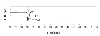
- FIG. 5A is a diagram showing the temporal transition of the rotation speed in the experiment for confirming the HC slip behavior when the load is increased.
- FIG. 5B is a diagram showing a temporal transition of torque in an experiment for confirming HC slip behavior when a load is increased.
- FIG. 5C is a diagram showing the temporal transition of the HC amount in the experiment for confirming the HC slip behavior when the load is increased. These have the same horizontal axis.
- C1 shown by a broken line shows the time transition at the time of loading when the inlet temperature of the DOC 31 is 240 ° C. at a rotation speed of 1000 rpm.
- C2 shown by a solid line shows the time transition at the time of loading when the inlet temperature of the DOC 31 is 270 ° C. at a rotation speed of 1000 rpm.
- C3 shown by the alternate long and short dash line shows the time transition at the time of loading when the inlet temperature of the DOC 31 is 300 ° C. at a rotation speed of 1000 rpm.
- Information indicating the correspondence relationship is set based on the knowledge of such experimental results.
- the excess air rate when the temperature index of DOC31 is higher than the first temperature at the second temperature is smaller than the excess air rate when the temperature index of DOC31 is the first temperature. preferable.
- FIG. 6 is a diagram showing an example of information indicating a correspondence relationship stored in the reproduction control device 2 according to the embodiment.
- the information indicating the correspondence relationship may be a table showing the relationship between the DOC inlet temperature as the temperature index of the DOC 31 and the lower limit value of the exhaust air excess rate as the air excess rate. ..
- the lower limit of the exhaust air excess rate is set to A1.
- the lower limit of the exhaust air excess rate is set to A2.
- A3 is set when the DOC inlet temperature is 270 ° C
- A4 is set when the DOC inlet temperature is 280 ° C
- A5 is set when the DOC inlet temperature is 300 ° C
- the DOC inlet is set.
- A6 is set.
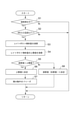
- FIG. 7 is a flowchart for explaining an example of the process executed by the reproduction control device 2 according to the embodiment.
- the processing related to the operation of the late post injection amount determination unit 23 will be described.
- the reproduction control device 2 determines whether or not the forced reproduction process is being executed (step S1). When it is determined that the forced reproduction process is not being executed (step S1; No), the reproduction control device 2 skips the subsequent processes and returns. When it is determined that the forced regeneration process is being executed (step S1; Yes), the regeneration control device 2 determines whether or not the inlet temperature of the DOC 31 is equal to or higher than the predetermined temperature T1 (step S2). In step S2, the regeneration control device 2 may compare the DOC temperature index with the predetermined temperature T1 instead of the inlet temperature of the DOC 31.
- step S3 When it is determined that the inlet temperature of the DOC 31 is not equal to or higher than the predetermined temperature T1 (step S2; No), the reproduction control device 2 skips the subsequent processing and returns.
- the late post injection amount determining unit 23 of the reproduction control device 2 determines the late post injection amount (that is, the basic injection amount and the correction injection amount). The added value) is calculated (step S3).
- the late post injection amount determination unit 23 of the reproduction control device 2 has an upper limit of the late post injection amount based on the excess air ratio of the exhaust gas flowing into the DOC 31 acquired based on the temperature index of the DOC 31 (for example, the inlet temperature of the DOC 31). Calculate the value (step S4).
- the late post injection amount determination unit 23 of the reproduction control device 2 determines whether or not the calculated value (that is, the added value) exceeds the upper limit value (step S5).
- the late post injection amount determination unit 23 determines the late post injection amount as the upper limit value (step S6). Freezes the integration operation of the PID calculation unit 63 (step S7). When it is determined that the calculated value (that is, the added value) does not exceed the upper limit value (step S5; No), the late post injection amount determining unit 23 determines the late post injection amount as the calculated value (that is, the added value) (that is, the added value). Step S8).
- Steps S5 to S8 are realized by limiting the late post injection amount of the limiting unit 81.
- the reproduction control device 2 performs late post injection based on the determined late post injection amount. It should be noted that the calculated value (that is, the added value) and the upper limit value of the late post injection amount need to be calculated so as to change from moment to moment. Therefore, these processes return to step S1 again, and the calculation is repeated.
- FIG. 8 is a diagram for explaining the experimental results of Examples and Comparative Examples in comparison with each other.
- the regeneration control device 2 according to the above embodiment is used to acquire the HC slip maximum concentration and the forced regeneration processing time of the DPF 32 for each of the four operation patterns (operation patterns 1 to 4).
- the inlet temperature of the DOC 31 at the maximum HC slip is changed.
- the inlet temperature of the DOC 31 at the maximum HC slip is the same, but the rotation speed and the way of increasing the load are changed.
- the comparative example shows the result when the limit based on the upper limit value of the late post injection amount is not applied, and the embodiment shows the result when the limit is applied based on the upper limit value of the late post injection amount.
- the HC slip maximum concentration is significantly reduced as compared with the comparative example.
- the forced regeneration time did not increase as compared with the comparative example, and there was no adverse effect. From these experimental results, it can be seen that the limitation based on the upper limit of the late post injection amount is meaningful.
- the present disclosure is not limited to the above-mentioned embodiment, and includes a form in which the above-mentioned embodiment is modified and a form in which a plurality of embodiments are appropriately combined.
- the reproduction control device (2) is The exhaust gas treatment device (3) of the diesel engine (1) including the diesel oxidation catalyst (DOC31) arranged in the exhaust passage (16) of the internal combustion engine and the diesel particulate filter (DPF32) arranged downstream of the DOC (31). ), The regeneration control device (2) for controlling the execution of forced regeneration that removes the exhaust fine particles (PM) accumulated on the DPF (32) by raising the temperature of the DPF (32).
- a late post injection amount determination unit (23) for determining the late post injection amount is provided.
- the late post injection amount determining unit (23) has an upper limit of the late post injection amount based on the excess air ratio of the exhaust gas flowing into the DOC (31) acquired based on the temperature index of the DOC (31). It is configured to determine the value.
- the upper limit of the late post injection amount is determined based on the excess air ratio of the exhaust gas flowing into the DOC (31) acquired based on the temperature index of the DOC (31). Therefore, it is possible to realize fine control so as not to excessively suppress the late post injection amount while reducing the generation of white smoke. As a result, it does not have an adverse effect such as an increase in DPF regeneration time. Further, since the excess air ratio of the exhaust gas is used in determining the upper limit value of the late post injection amount, more accurate control can be realized as compared with the case of using the excess air ratio of the supply air.
- a storage unit (25) for storing information indicating the correspondence between the temperature index of the DOC (31) and the excess air ratio is provided.
- the late post injection amount determination unit (23) is configured to determine an upper limit value of the late post injection amount with reference to the information indicating the correspondence relationship.
- the excess air ratio when the temperature index of the DOC (31) is a second temperature higher than the first temperature is the said when the temperature index of the DOC is the first temperature. Equivalent or smaller than the excess air rate.
- the injection amount of unburned fuel that can be oxidized by DOC (31) increases as the temperature index of DOC (31) increases.
- the excess air ratio when the temperature index of the DOC (31) is the second temperature higher than the first temperature is the air when the temperature index of the DOC (31) is the first temperature. Equivalent or smaller than the excess rate.
- the upper limit of the late post injection amount is determined using such an excess air ratio. In this case, the upper limit of the late post injection amount can be determined to be an appropriate value according to the injection amount of the unburned fuel that can be oxidized by the DOC (31).
- the late post injection amount determination unit (23) A feedforward control unit (47) for determining the basic injection amount of the late post injection amount based on the operating conditions of the internal combustion engine, and A feedback control unit (49) for determining the corrected injection amount of the late post injection amount based on the deviation between the inlet temperature and the target temperature of the DPF (32), Including
- the late post injection amount determining unit (23) uses the added value as the late post injection amount.
- the late post injection amount is limited to the upper limit of the late post injection amount.
- the feedback control unit (49) has a PID calculation unit (63).
- the late post injection amount determination unit (23) freezes the integration operation of the PID calculation unit (63) at least for a part of the time during which the late post injection amount is limited to the upper limit value of the late post injection amount. Let me.
Priority Applications (2)
| Application Number | Priority Date | Filing Date | Title |
|---|---|---|---|
| US18/015,904 US20230279798A1 (en) | 2020-09-07 | 2021-07-20 | Regeneration control apparatus |
| EP21863972.2A EP4174292A4 (de) | 2020-09-07 | 2021-07-20 | Regenerationssteuerungsvorrichtung |
Applications Claiming Priority (2)
| Application Number | Priority Date | Filing Date | Title |
|---|---|---|---|
| JP2020149765A JP7471180B2 (ja) | 2020-09-07 | 2020-09-07 | 再生制御装置 |
| JP2020-149765 | 2020-09-07 |
Publications (1)
| Publication Number | Publication Date |
|---|---|
| WO2022049914A1 true WO2022049914A1 (ja) | 2022-03-10 |
Family
ID=80491944
Family Applications (1)
| Application Number | Title | Priority Date | Filing Date |
|---|---|---|---|
| PCT/JP2021/027152 WO2022049914A1 (ja) | 2020-09-07 | 2021-07-20 | 再生制御装置 |
Country Status (4)
| Country | Link |
|---|---|
| US (1) | US20230279798A1 (de) |
| EP (1) | EP4174292A4 (de) |
| JP (1) | JP7471180B2 (de) |
| WO (1) | WO2022049914A1 (de) |
Cited By (2)
| Publication number | Priority date | Publication date | Assignee | Title |
|---|---|---|---|---|
| CN114753938A (zh) * | 2022-05-09 | 2022-07-15 | 潍柴动力股份有限公司 | 再生温度控制方法、装置、设备、介质及产品 |
| CN115263501A (zh) * | 2022-08-11 | 2022-11-01 | 潍柴动力扬州柴油机有限责任公司 | 一种控制dpf再生时温度偏差大的方法 |
Citations (5)
| Publication number | Priority date | Publication date | Assignee | Title |
|---|---|---|---|---|
| JP2004197697A (ja) * | 2002-12-20 | 2004-07-15 | Isuzu Motors Ltd | 燃料噴射制御装置 |
| JP2007198283A (ja) | 2006-01-27 | 2007-08-09 | Isuzu Motors Ltd | 排気ガス浄化方法及び排気ガス浄化システム |
| JP2011231645A (ja) * | 2010-04-26 | 2011-11-17 | Toyota Motor Corp | 内燃機関の排気浄化装置 |
| JP2012092759A (ja) * | 2010-10-27 | 2012-05-17 | Mitsubishi Heavy Ind Ltd | ディーゼルエンジンの排気浄化装置 |
| JP2020149765A (ja) | 2019-03-11 | 2020-09-17 | 矢崎総業株式会社 | バッテリモジュール及びバッテリパック |
Family Cites Families (6)
| Publication number | Priority date | Publication date | Assignee | Title |
|---|---|---|---|---|
| JP4013813B2 (ja) * | 2003-04-04 | 2007-11-28 | 日産自動車株式会社 | ディーゼルエンジン用排気浄化装置 |
| JP2007321614A (ja) * | 2006-05-31 | 2007-12-13 | Toyota Motor Corp | 内燃機関の排気浄化装置 |
| US8302385B2 (en) * | 2008-05-30 | 2012-11-06 | Cummins Ip, Inc. | Apparatus, system, and method for controlling engine exhaust temperature |
| GB2476959B (en) * | 2010-01-15 | 2016-03-09 | Gm Global Tech Operations Inc | Method for operating post injections of fuel in an internal combustion engine |
| SE536169C2 (sv) * | 2010-08-31 | 2013-06-11 | Scania Cv Ab | Förfarande och system för avgasrening |
| JP6432411B2 (ja) * | 2015-03-25 | 2018-12-05 | いすゞ自動車株式会社 | 排気浄化システム |
-
2020
- 2020-09-07 JP JP2020149765A patent/JP7471180B2/ja active Active
-
2021
- 2021-07-20 EP EP21863972.2A patent/EP4174292A4/de active Pending
- 2021-07-20 WO PCT/JP2021/027152 patent/WO2022049914A1/ja unknown
- 2021-07-20 US US18/015,904 patent/US20230279798A1/en active Pending
Patent Citations (5)
| Publication number | Priority date | Publication date | Assignee | Title |
|---|---|---|---|---|
| JP2004197697A (ja) * | 2002-12-20 | 2004-07-15 | Isuzu Motors Ltd | 燃料噴射制御装置 |
| JP2007198283A (ja) | 2006-01-27 | 2007-08-09 | Isuzu Motors Ltd | 排気ガス浄化方法及び排気ガス浄化システム |
| JP2011231645A (ja) * | 2010-04-26 | 2011-11-17 | Toyota Motor Corp | 内燃機関の排気浄化装置 |
| JP2012092759A (ja) * | 2010-10-27 | 2012-05-17 | Mitsubishi Heavy Ind Ltd | ディーゼルエンジンの排気浄化装置 |
| JP2020149765A (ja) | 2019-03-11 | 2020-09-17 | 矢崎総業株式会社 | バッテリモジュール及びバッテリパック |
Non-Patent Citations (1)
| Title |
|---|
| See also references of EP4174292A4 |
Cited By (2)
| Publication number | Priority date | Publication date | Assignee | Title |
|---|---|---|---|---|
| CN114753938A (zh) * | 2022-05-09 | 2022-07-15 | 潍柴动力股份有限公司 | 再生温度控制方法、装置、设备、介质及产品 |
| CN115263501A (zh) * | 2022-08-11 | 2022-11-01 | 潍柴动力扬州柴油机有限责任公司 | 一种控制dpf再生时温度偏差大的方法 |
Also Published As
| Publication number | Publication date |
|---|---|
| US20230279798A1 (en) | 2023-09-07 |
| EP4174292A1 (de) | 2023-05-03 |
| JP2022044234A (ja) | 2022-03-17 |
| JP7471180B2 (ja) | 2024-04-19 |
| EP4174292A4 (de) | 2023-11-15 |
Similar Documents
| Publication | Publication Date | Title |
|---|---|---|
| US6598387B2 (en) | Reduction of exhaust smoke emissions following extended diesel engine idling | |
| US20060016180A1 (en) | Apparatus and method for preventing overheating of exhaust purification filter | |
| WO2012053279A1 (ja) | ディーゼルエンジンの排気浄化装置 | |
| EP1555401A1 (de) | Abgasreinigungsanlage für Verbrennungskraftmaschine | |
| WO2022049914A1 (ja) | 再生制御装置 | |
| JP5846286B2 (ja) | 内燃機関の排気浄化装置 | |
| JP2006316746A (ja) | 内燃機関の排ガス浄化装置 | |
| JP4544011B2 (ja) | 内燃機関排気浄化装置 | |
| JP7132798B2 (ja) | Dpf再生制御装置及びdpf再生制御方法 | |
| JP5332575B2 (ja) | 内燃機関の排気浄化装置 | |
| WO2016117516A1 (ja) | 排気浄化システム及び触媒再生方法 | |
| EP2450540B1 (de) | Abgasreinigungsvorrichtung für einen verbrennungsmotor | |
| JP2008069648A (ja) | パティキュレートフィルタの再生制御装置 | |
| WO2016143822A1 (ja) | 排気浄化システム及び排気浄化システムの制御方法 | |
| JP5887991B2 (ja) | 排気浄化装置 | |
| JP4710815B2 (ja) | 内燃機関の排気浄化装置 | |
| EP1536120B1 (de) | Abgassteuerungsvorrichtung und -methode für eine Brennkraftmaschine | |
| JP4613787B2 (ja) | 内燃機関の排気浄化装置 | |
| WO2017010550A1 (ja) | 排気浄化システム | |
| JP6405858B2 (ja) | Pto装置付き車両のdpf再生システム | |
| JP6439334B2 (ja) | 排気浄化システム | |
| JP5240514B2 (ja) | エンジンの排気還流装置 | |
| JP5796277B2 (ja) | 排気ガス浄化システム | |
| JP5625489B2 (ja) | 高地における排ガス浄化システム | |
| JP2007040223A (ja) | 排気浄化装置 |
Legal Events
| Date | Code | Title | Description |
|---|---|---|---|
| 121 | Ep: the epo has been informed by wipo that ep was designated in this application |
Ref document number: 21863972 Country of ref document: EP Kind code of ref document: A1 |
|
| ENP | Entry into the national phase |
Ref document number: 2021863972 Country of ref document: EP Effective date: 20230125 |
|
| NENP | Non-entry into the national phase |
Ref country code: DE |