WO2022044732A1 - ワイヤハーネスユニット - Google Patents
ワイヤハーネスユニット Download PDFInfo
- Publication number
- WO2022044732A1 WO2022044732A1 PCT/JP2021/028870 JP2021028870W WO2022044732A1 WO 2022044732 A1 WO2022044732 A1 WO 2022044732A1 JP 2021028870 W JP2021028870 W JP 2021028870W WO 2022044732 A1 WO2022044732 A1 WO 2022044732A1
- Authority
- WO
- WIPO (PCT)
- Prior art keywords
- conductor
- tubular conductor
- tubular
- cooling tube
- conductive path
- Prior art date
- Legal status (The legal status is an assumption and is not a legal conclusion. Google has not performed a legal analysis and makes no representation as to the accuracy of the status listed.)
- Ceased
Links
Images


Classifications
-
- B—PERFORMING OPERATIONS; TRANSPORTING
- B60—VEHICLES IN GENERAL
- B60R—VEHICLES, VEHICLE FITTINGS, OR VEHICLE PARTS, NOT OTHERWISE PROVIDED FOR
- B60R16/00—Electric or fluid circuits specially adapted for vehicles and not otherwise provided for; Arrangement of elements of electric or fluid circuits specially adapted for vehicles and not otherwise provided for
- B60R16/02—Electric or fluid circuits specially adapted for vehicles and not otherwise provided for; Arrangement of elements of electric or fluid circuits specially adapted for vehicles and not otherwise provided for electric constitutive elements
- B60R16/0207—Wire harnesses
- B60R16/0215—Protecting, fastening and routing means therefor
-
- B—PERFORMING OPERATIONS; TRANSPORTING
- B60—VEHICLES IN GENERAL
- B60R—VEHICLES, VEHICLE FITTINGS, OR VEHICLE PARTS, NOT OTHERWISE PROVIDED FOR
- B60R16/00—Electric or fluid circuits specially adapted for vehicles and not otherwise provided for; Arrangement of elements of electric or fluid circuits specially adapted for vehicles and not otherwise provided for
- B60R16/02—Electric or fluid circuits specially adapted for vehicles and not otherwise provided for; Arrangement of elements of electric or fluid circuits specially adapted for vehicles and not otherwise provided for electric constitutive elements
-
- H—ELECTRICITY
- H01—ELECTRIC ELEMENTS
- H01B—CABLES; CONDUCTORS; INSULATORS; SELECTION OF MATERIALS FOR THEIR CONDUCTIVE, INSULATING OR DIELECTRIC PROPERTIES
- H01B7/00—Insulated conductors or cables characterised by their form
-
- H—ELECTRICITY
- H01—ELECTRIC ELEMENTS
- H01B—CABLES; CONDUCTORS; INSULATORS; SELECTION OF MATERIALS FOR THEIR CONDUCTIVE, INSULATING OR DIELECTRIC PROPERTIES
- H01B7/00—Insulated conductors or cables characterised by their form
- H01B7/42—Insulated conductors or cables characterised by their form with arrangements for heat dissipation or conduction
-
- H—ELECTRICITY
- H02—GENERATION; CONVERSION OR DISTRIBUTION OF ELECTRIC POWER
- H02G—INSTALLATION OF ELECTRIC CABLES OR LINES, OR OF COMBINED OPTICAL AND ELECTRIC CABLES OR LINES
- H02G3/00—Installations of electric cables or lines or protective tubing therefor in or on buildings, equivalent structures or vehicles
- H02G3/02—Details
- H02G3/03—Cooling
-
- H—ELECTRICITY
- H02—GENERATION; CONVERSION OR DISTRIBUTION OF ELECTRIC POWER
- H02G—INSTALLATION OF ELECTRIC CABLES OR LINES, OR OF COMBINED OPTICAL AND ELECTRIC CABLES OR LINES
- H02G3/00—Installations of electric cables or lines or protective tubing therefor in or on buildings, equivalent structures or vehicles
- H02G3/02—Details
- H02G3/04—Protective tubing or conduits, e.g. cable ladders or cable troughs
-
- H—ELECTRICITY
- H02—GENERATION; CONVERSION OR DISTRIBUTION OF ELECTRIC POWER
- H02G—INSTALLATION OF ELECTRIC CABLES OR LINES, OR OF COMBINED OPTICAL AND ELECTRIC CABLES OR LINES
- H02G3/00—Installations of electric cables or lines or protective tubing therefor in or on buildings, equivalent structures or vehicles
- H02G3/02—Details
- H02G3/04—Protective tubing or conduits, e.g. cable ladders or cable troughs
- H02G3/0462—Tubings, i.e. having a closed section
- H02G3/0481—Tubings, i.e. having a closed section with a circular cross-section
Definitions
- This disclosure relates to a wire harness unit.
- wire harnesses mounted on vehicles such as hybrid vehicles and electric vehicles electrically connect multiple electric devices. Further, in an electric vehicle, the vehicle and the ground equipment are connected by a wire harness, and the power storage device mounted on the vehicle is charged from the ground equipment. As the voltage supplied by the wire harness increases, the amount of heat generated by the wire harness increases. Therefore, a configuration for cooling the wire harness has been proposed.
- Patent Document 1 includes a coated electric wire, an inner cylinder covering the coated electric wire, and an outer cylinder covering the inner cylinder at a predetermined interval, and a circulation passage for a cooling medium is provided between the inner cylinder and the outer cylinder.
- the wire harness formed is disclosed.
- the circulation passage is formed by an inner and outer cylinders that are separate from the covered electric wire, and the coated electric wire is arranged inside the radial side of the distribution path.
- the purpose of the present disclosure is to provide a wire harness unit capable of improving cooling efficiency.
- the wire harness unit includes a plurality of conductive paths for conducting electricity between in-vehicle devices and a cooling unit for cooling the plurality of conductive paths, and the plurality of conductive paths are the first.
- the first conductive path has a conductive path and a second conductive path alongside the first conductive path, the first conductive path has a hollow first tubular conductor having conductivity, and the second conductive path has a conductive path. It has a hollow second tubular conductor having conductivity, and the cooling portion is a separate body from the first tubular conductor and the second tubular conductor while allowing a cooling medium to flow inside.
- the first tubular conductor and the second tubular conductor are more rigid than the cooling tube, and the cooling tube is a first penetrating the first tubular conductor. It has a section, a second section penetrating the second tubular conductor, and a folded portion connecting the first section and the second section.
- the cooling efficiency can be improved.
- FIG. 1 is a schematic view showing a vehicle to which a wire harness unit is arranged according to an embodiment.
- FIG. 2 is a schematic view of the wire harness unit.
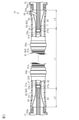
- FIG. 3 is a partial cross-sectional view showing an outline of the wire harness unit.
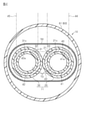
- FIG. 4 is a cross-sectional view of the wire harness unit.
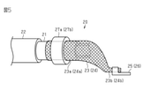
- FIG. 5 is an explanatory diagram showing the connection between the cylindrical conductor, the flexible conductor, and the terminal.
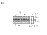
- FIG. 6 is a schematic view showing a part of the wire harness unit.
- the wire harness unit of the present disclosure is [1] A plurality of conductive paths for conducting electricity between in-vehicle devices and a cooling unit for cooling the plurality of conductive paths are provided, and the plurality of conductive paths include a first conductive path and the first conductive path.
- the first conductive path has a hollow first tubular conductor having conductivity
- the second conductive path has a hollow second tubular conductor having conductivity.
- the cooling unit has a shaped conductor, and the cooling unit has a cooling medium that allows a cooling medium to flow inside and has a cooling tube that is separate from the first tubular conductor and the second tubular conductor.
- the tubular conductor and the second tubular conductor are more rigid than the cooling tube, and the cooling tube has a first section penetrating the first tubular conductor and the second tubular conductor. It has a second section penetrating the above, and a folded portion connecting the first section and the second section.
- the first section of the cooling tube penetrates the first tubular conductor and the second section penetrates the second tubular conductor, so that the cooling medium has the first tubular conductor and the second tubular conductor. It is possible to circulate inside the conductor. Therefore, the first cylindrical conductor and the second tubular conductor can be cooled from the inside, and the cooling efficiency can be improved.
- the cooling tube has a folded portion connecting the first section and the second section, for example, the flow of the cooling medium is compared with the case where the cooling tube is provided for each conductive path without having the folded portion.
- the number of inlets and outlets can be reduced, and the connection structure with the pump can be simplified. Further, for example, the number of cooling tubes can be reduced and the number of parts can be reduced as compared with the case where the cooling tubes are provided for each conductive path without having a folded portion.
- the number of conductive paths included in the plurality of conductive paths is preferably an even number.
- the positions of the inlet and outlet of the cooling medium can be easily set to nearby positions. That is, the plurality of conductive paths are, for example, three, which is an odd number, and the cooling tube has a third section, a second section, and a third section penetrating the third tubular conductor in the third conductive path. If a folding portion for connecting is further provided, the positions of the inlet and outlet of the cooling medium will be far apart, but this will be avoided. Therefore, for example, the positions of the inlet and outlet of the cooling medium can be easily integrated, and for example, the wiring space for connecting to the pump can be reduced.
- the exterior member includes an exterior member that covers the conductive path, the exterior member has a tubular exterior member and a grommet connected to an end portion of the tubular exterior member, and the folded portion is of the grommet. It is preferably placed inside.
- the folded portion is arranged inside the grommet, for example, the folded portion can be easily accommodated. For example, even when a large space is required due to a configuration in which the folded portion is not sharply bent, it can be easily dealt with without increasing the overall size of the tubular exterior member. Further, for example, in the case of a shape in which the size of the grommet increases toward the connected member, the folded portion can be easily accommodated in a wide space.
- the outer peripheral surface of the cooling tube is in contact with the inner peripheral surface of the first tubular conductor and the inner peripheral surface of the second tubular conductor.
- the outer peripheral surface of the cooling tube through which the cooling medium is circulated is in contact with the inner peripheral surface of the first cylindrical conductor and the inner peripheral surface of the second tubular conductor, so that the outer peripheral surface has a more first cylindrical shape.
- the conductor and the second cylindrical conductor can be cooled.
- Both the first conductive path and the second conductive path have a flexible conductor and a terminal, and the flexible conductor is electrically with the first tubular conductor or the second tubular conductor. It has a first end to be connected and a second end to be electrically connected to the terminal, the flexible conductor being more flexible than the first tubular conductor and the second tubular conductor. It is preferable to have.
- the flexible conductor is connected to the end of the first cylindrical conductor and the second tubular conductor, so that the dimensional tolerance of the conductive path can be absorbed. Furthermore, it is also a countermeasure against rocking that occurs when the vehicle is running.
- the first tubular conductor and the second tubular conductor are preferably longer than the flexible conductor.
- the section in which the cooling tube contacts the first tubular conductor and the second tubular conductor becomes longer, and the first The tubular conductor and the second tubular conductor can be cooled more.
- An electromagnetic shield member that covers at least a part of the cooling tube, the first tubular conductor, and the second tubular conductor is provided, and the electromagnetic shield member is a braided member in which a metal wire is braided. It is preferable that a part of the cooling tube penetrates the braided member.
- both the shielding property of suppressing the radiation of electromagnetic noise from the conductive path and the assembly workability of the cooling unit can be achieved.
- the exterior member includes an exterior member that covers the conductive path, the exterior member has a tubular exterior member and a grommet connected to an end portion of the tubular exterior member, and the cooling tube has the grommet. It is preferable that it penetrates.
- the wire harness unit 10 shown in FIG. 1 electrically connects two in-vehicle devices mounted on the vehicle V.
- the vehicle V is, for example, a hybrid vehicle, an electric vehicle, or the like.
- the wire harness unit 10 has a conductive path 11 that electrically connects the vehicle-mounted device M1 and the vehicle-mounted device M2, and an exterior member 60 that covers the conductive path 11.
- the conductive path 11 is routed from the vehicle-mounted device M1 to the vehicle-mounted device M2 in such a manner that a part of the conductive path 11 passes under the floor of the vehicle V, for example.
- the in-vehicle device M1 is an inverter installed closer to the front of the vehicle V
- the in-vehicle device M2 is a high-voltage battery installed behind the vehicle V than the in-vehicle device M1.
- the vehicle-mounted device M1 as an inverter is connected to, for example, a wheel driving motor (not shown) that is a power source for traveling the vehicle.
- the inverter generates AC power from the DC power of the high-voltage battery and supplies the AC power to the motor.
- the vehicle-mounted device M2 as a high-voltage battery is, for example, a battery capable of supplying a voltage of 100 volts or more. That is, the conductive path 11 of the present embodiment constitutes a high-voltage circuit that enables high-voltage exchange between the high-voltage battery and the inverter.
- the wire harness unit 10 has a plurality of conductive paths 11, a cooling tube 40, an electromagnetic shield member 50, an exterior member 60, and connectors 71 and 72.
- the plurality of conductive paths 11 have a first conductive path 20 and a second conductive path 30 alongside the first conductive path 20.
- the first conductive path 20 has a first cylindrical conductor 21, an insulating coating 22, flexible conductors 23, 24, and terminals 25, 26.
- the first cylindrical conductor 21 has conductivity and has a hollow structure inside.
- the first cylindrical conductor 21 is made of metal, for example, and has high shape retention. That is, the first cylindrical conductor 21 can retain its shape.
- the material of the first tubular conductor 21 is, for example, a metal material such as copper-based or aluminum-based.
- the first cylindrical conductor 21 is formed in a shape that matches the arrangement path of the wire harness unit 10 shown in FIG.
- the first cylindrical conductor 21 is bent by a pipe bender (in other words, a pipe bending device).
- FIG. 4 shows a cross section of the wire harness unit 10 cut along a plane orthogonal to the length direction of the wire harness unit 10.
- the length direction of the first cylindrical conductor 21 is the front and back directions of the paper surface of FIG.
- the cross-sectional shape of the first tubular conductor 21 can be any shape. Further, in the cross-sectional shape of the first tubular conductor 21, the outer peripheral shape and the inner peripheral shape may be different from each other. Further, the cross-sectional shape may be different in the length direction of the first tubular conductor 21.
- the insulating coating 22 covers, for example, the outer peripheral surface of the first tubular conductor 21 over the entire circumference in the circumferential direction.
- the insulating coating 22 is made of an insulating material such as a synthetic resin.
- a silicone resin for example, a synthetic resin containing a polyolefin resin such as cross-linked polyethylene or cross-linked polypropylene as a main component, or the like can be used.
- a silicone resin a synthetic resin containing a polyolefin resin such as cross-linked polyethylene or cross-linked polypropylene as a main component, or the like can be used.
- the material of the insulating coating 22 one kind of material can be used alone, or two or more kinds of materials can be used in combination as appropriate.
- the insulating coating 22 can be formed, for example, by extrusion molding (extrusion coating) on the first cylindrical conductor 21.
- the first cylindrical conductor 21 has a first end portion 21a and a second end portion 21b which are both ends in the length direction of the first tubular conductor 21.
- the first end portion 21a and the second end portion 21b are exposed from the insulating coating 22.
- the flexible conductor 23 and 24 are connected to the first end portion 21a and the second end portion 21b, respectively, and the other ends of the flexible conductors 23 and 24 are shown in FIG. Terminals 25 and 26 are connected. More specifically, the flexible conductor 23 is electrically connected to the first end portion 23a, which is electrically connected to the first end portion 21a of the first cylindrical conductor 21, and the terminal 25 shown in FIGS. 2 and 5. It has a second end portion 23b.
- the flexible conductor 24 includes a first end portion 24a electrically connected to the second end portion 21b of the first cylindrical conductor 21 and a second end portion 24b electrically connected to the terminal 26 shown in FIG. have.
- the flexible conductors 23 and 24 are conductors having better flexibility than the first tubular conductor 21.
- the flexible conductors 23 and 24 of this embodiment are formed in a cylindrical shape.
- the flexible conductors 23 and 24 are, for example, braided wires in which conductive strands are woven into a cylinder.
- the wire material is, for example, a copper-based or aluminum-based metal material.
- the first end portion 21a of the first tubular conductor 21 is arranged inside the first end portion 23a of the flexible conductor 23 formed in a cylindrical shape. That is, the first end portion 23a of the tubular flexible conductor 23 covers the first end portion 21a of the first tubular conductor 21.
- a tightening band 27a is attached to the outer peripheral side of the flexible conductor 23.
- the flexible conductor 23 is crimped to the outer peripheral surface of the first tubular conductor 21 by the tightening band 27a.
- the tightening band 27a electrically connects the first end portion 23a of the flexible conductor 23 to the outer peripheral surface of the first end portion 21a of the first tubular conductor 21.
- the first cylindrical conductor 21 and the flexible conductor 23 may be connected by welding such as ultrasonic welding.
- the second end portion 21b of the first tubular conductor 21 is arranged inside the first end portion 24a of the flexible conductor 24 formed in a cylindrical shape. That is, the first end portion 24a of the tubular flexible conductor 24 covers the second end portion 21b of the first tubular conductor 21.
- a tightening band 27b is attached to the outer peripheral side of the flexible conductor 24.
- the flexible conductor 24 is crimped to the outer peripheral surface of the first tubular conductor 21 by the tightening band 27b.
- the tightening band 27b electrically connects the first end portion 24a of the flexible conductor 24 to the outer peripheral surface of the second end portion 21b of the first tubular conductor 21.
- the flexible conductor 24 and the first cylindrical conductor 21 may be connected by welding such as ultrasonic welding.
- FIG. 5 is an explanatory diagram showing the connection between the first cylindrical conductor, the flexible conductor, and the terminal.
- the members shown on the left side of FIGS. 2 and 3 are indicated by reference numerals without parentheses, and the members shown on the right side of FIGS. 2 and 3 are indicated by reference numerals with parentheses. show.
- the terminal 25 is held by the connector 71 shown in FIGS. 1 and 2 and is connected to the in-vehicle device M1.
- the terminal 25 is connected to the second end 23b of the flexible conductor 23.
- the terminal 25 has a pair of crimping pieces, and the crimping pieces are crimped to the second end portion 23b of the flexible conductor 23.
- the terminal 26 is held by the connector 72 shown in FIGS. 1 and 2 and is connected to the in-vehicle device M2.
- the terminal 26 is connected to the second end portion 24b of the flexible conductor 24.
- the terminal 26 has a pair of crimping pieces, and the crimping pieces are crimped to the second end portion 24b of the flexible conductor 24.
- the second conductive path 30 has a second cylindrical conductor 31, an insulating coating 32, flexible conductors 23, 24, and terminals 25, 26. As shown in FIGS. 4 and 6, the second conductive path 30 is arranged side by side with the first conductive path 20.
- the second conductive path 30 is configured in the same manner as the first conductive path 20, and for example, the second tubular conductor 31 is a part having the same part number as the first tubular conductor 21.
- the same components as the components in the first conductive path 20 are designated by the same names and reference numerals, and detailed description thereof will be omitted.
- the cooling tube 40 is formed in a hollow shape.
- the cooling tube 40 is more flexible than the first cylindrical conductor 21 and the second tubular conductor 31.
- the first cylindrical conductor 21 and the second tubular conductor 31 are more rigid than the cooling tube 40.
- the cooling tube 40 includes a first section 41 penetrating the first tubular conductor 21, a second section 42 penetrating the second tubular conductor 31, and a first section 41 and a second section 42. It has a folded-back portion 43 for connecting.
- the outer peripheral surface 41a of the first section 41 is in contact with the inner peripheral surface 21c of the first tubular conductor 21.
- the outer peripheral surface 42a of the second section 42 is in contact with the inner peripheral surface 31c of the second tubular conductor 31.
- a resin material such as an adhesive or an adhesive may be interposed between the outer peripheral surface 41a of the first section 41 and the inner peripheral surface 21c of the first tubular conductor 21.
- a resin material such as an adhesive or an adhesive may be interposed between the outer peripheral surface 42a of the second section 42 and the inner peripheral surface 31c of the second tubular conductor 31.
- a material having good thermal conductivity can be used. As shown in FIG.
- the folded-back portion 43 of the cooling tube 40 is provided on the first end portion 21a side of the first tubular conductor 21.
- the folded-back portion 43 is formed by being folded back so as to connect the first section 41 and the second section 42 while projecting outward from the first tubular conductor 21 and the second tubular conductor 31.
- the folded-back portion 43 of the present embodiment is provided so as to penetrate the flexible conductor 23.
- the material of the cooling tube 40 is a flexible resin material such as PP (polypropylene), PVC (polyvinyl chloride), cross-linked PE (polyethylene) and the like.
- a cooling medium 73 is supplied to the inside of the cooling tube 40.
- the cooling medium 73 is, for example, various fluids such as a liquid such as water and antifreeze, a gas, and a gas-liquid two-phase flow in which a gas and a liquid are mixed.
- the cooling medium 73 is supplied by a pump (not shown).
- the cooling tube 40 forms part of a circulation path that circulates in the cooling medium 73.
- the circulation path includes, for example, the above-mentioned pump and heat dissipation unit.
- the pump pumps the cooling medium 73 to the cooling tube 40.
- the cooling medium 73 supplied to the cooling tube 40 exchanges heat with the first cylindrical conductor 21 and the second tubular conductor 31 located outside the cooling tube 40.
- the heat radiating unit dissipates the heat of the cooling medium 73 whose temperature has risen due to heat exchange to the outside, and cools the cooling medium 73.
- the cooled cooling medium 73 is pumped back to the cooling tube 40 by the pump.
- the cooling tube 40 constitutes a cooling unit that cools the first tubular conductor 21 and the second tubular conductor 31 by the cooling medium 73 that circulates in this way.
- the electromagnetic shield member 50 covers the two conductive paths 11.
- the electromagnetic shield member 50 is a braided member in which a metal wire is braided into a cylindrical shape.
- the electromagnetic shield member 50 has a shielding property. Further, the electromagnetic shield member 50 has flexibility. As shown in FIG. 3, one end of the electromagnetic shield member 50 is connected to the connector 71, and the other end of the electromagnetic shield member 50 is connected to the connector 72. Therefore, the electromagnetic shield member 50 covers the entire length of the conductive path 11 that transmits a high voltage. This suppresses the radiation of electromagnetic noise generated from the conductive path 11 to the outside.
- the exterior member 60 covers the conductive path 11.
- the cooling tube 40 penetrates the first tubular conductor 21 and the second tubular conductor 31 of the conductive path 11. Therefore, the exterior member 60 covers at least a part of the conductive path 11 and the cooling tube 40.
- the exterior member 60 has a cylindrical exterior member 61 and grommets 62 and 63 connected to the first end portion 61a and the second end portion 61b of the cylindrical exterior member 61, respectively.
- the tubular exterior member 61 is provided so as to cover, for example, a part of the outer periphery of the first tubular conductor 21 and the second tubular conductor 31 in the length direction.
- the tubular exterior member 61 has, for example, a cylindrical shape in which both ends of the first tubular conductor 21 and the second tubular conductor 31 in the length direction are open.
- the tubular exterior member 61 is provided, for example, so as to surround the outer periphery of the first tubular conductor 21 and the second tubular conductor 31 over the entire circumference in the circumferential direction.
- the tubular exterior member 61 of the present embodiment is formed in a cylindrical shape.
- the tubular exterior member 61 has, for example, a bellows structure in which annular protrusions and annular recesses are alternately arranged along an axis direction (length direction) in which the central axis of the tubular exterior member 61 extends. ..
- a resin material having conductivity or a resin material having no conductivity can be used.
- synthetic resins such as polyolefin, polyamide, polyester, and ABS resin can be used.
- the tubular exterior member 61 of the present embodiment is a corrugated tube made of synthetic resin.
- the grommet 62 is formed in a substantially cylindrical shape.
- the grommet 62 is made of rubber, for example.
- the grommet 62 is formed so as to be hung between the connector 71 and the tubular exterior member 61.
- the grommet 62 is tightened and fixed by a tightening band 64a so as to be in close contact with the outer surface of the connector 71.
- the grommet 62 is fastened and fixed by a tightening band 64b so as to be in close contact with the outside of the first end portion 61a of the tubular exterior member 61.
- the folded-back portion 43 in the cooling tube 40 is arranged inside the grommet 62.
- the grommet 63 is formed in a substantially cylindrical shape.
- the grommet 63 is made of rubber, for example.
- the grommet 63 is formed so as to be hung between the connector 72 and the tubular exterior member 61.
- the grommet 63 is fastened and fixed by a tightening band 65a so as to be in close contact with the outer surface of the connector 72.
- the grommet 63 is fastened and fixed by a tightening band 65b so as to be in close contact with the outside of the second end portion 61b of the tubular exterior member 61.
- the grommet 63 is formed with a through hole 63a that penetrates the grommet 63.
- the through hole 63a communicates the inside and the outside of the grommet 63.
- the cooling tube 40 has an inflow portion 44 extending from the first section 41 and a discharge portion 45 extending from the second section 42 on the side opposite to the folded portion 43.
- Each through hole 63a is formed so as to be in close contact with the outer peripheral surfaces of the inflow portion 44 and the discharge portion 45 to be inserted therein.
- the inflow portion 44 penetrates the flexible conductor 24 and the electromagnetic shield member 50, and is led out from the through hole 63a of the grommet 63 to the outside of the grommet 63.
- the discharge portion 45 penetrates the flexible conductor 24 and the electromagnetic shield member 50, and is led out from the through hole 63a of the grommet 63 to the outside of the grommet 63.
- the inflow portion 44 constitutes the inflow port of the cooling medium 73 in the cooling tube 40.
- the discharge unit 45 constitutes a discharge port of the cooling medium 73 in the cooling tube 40.
- the inflow section 44 and the discharge section 45 are connected to the pump.
- the wire harness unit 10 includes a conductive path 11 that conducts electricity between the in-vehicle devices M1 and M2, and a cooling tube 40 that constitutes a cooling unit that cools the conductive path 11.
- the conductive path 11 has a hollow first tubular conductor 21 and a second tubular conductor 31 having conductivity, and the cooling tube 40 has a cooling medium 73 circulated inside and a first tubular conductor. It is a separate body from the 21 and the second tubular conductor 31.
- the first cylindrical conductor 21 and the second tubular conductor 31 are more rigid than the cooling tube 40.
- the cooling tube 40 has a first section 41 penetrating the first tubular conductor 21, a second section 42 penetrating the second tubular conductor 31, and a first section 41 and a second section 42. It has a folded-back portion 43 that connects and.
- a cooling medium 73 is supplied to the cooling tube 40.
- the cooling medium 73 flows in the order of the inflow section 44, the first section 41, the folded section 43, the second section 42, and the discharge section 45 in the cooling tube 40.
- the first tubular conductor 21 and the second tubular conductor 31 are cooled by heat exchange with the cooling medium 73 supplied to the cooling tube 40. In this way, the first cylindrical conductor 21 and the second tubular conductor 31 can be cooled from the inside.
- the outer peripheral length of the first tubular conductor 21 and the second tubular conductor 31 is longer than that of a stranded wire obtained by twisting a plurality of metal strands having the same cross-sectional area or a single core wire having a solid structure. That is, the area of the outer peripheral side of the first tubular conductor 21 and the second tubular conductor 31 is larger than that of the stranded wire or the single core wire. Therefore, heat can be dissipated from a larger area to the outside, so that heat dissipation can be improved.
- the conductive path 11 has flexible conductors 23 and 24 connected to the first cylindrical conductor 21 and the second tubular conductor 31.
- the flexible conductors 23 and 24 are more flexible than the first tubular conductor 21 and the second tubular conductor 31. Therefore, the dimensional tolerance of the conductive path 11 can be absorbed. Further, when the vehicle V vibrates, it is possible to absorb the positional deviation between the parts connected to both sides of the flexible conductors 23 and 24 caused by this vibration. In the present embodiment, for example, the positional deviation between the first cylindrical conductor 21 and the connectors 71 and 72, that is, between the first tubular conductor 21 and the in-vehicle devices M1 and M2 can be absorbed. Therefore, the load applied to the connectors 71 and 72 and the terminals 25 and 26 can be reduced.
- the length L1 of the first cylindrical conductor 21 and the second tubular conductor 31 is longer than the lengths L2 and L3 of the flexible conductors 23 and 24.
- the lengths L2 and L3 of the flexible conductors 23 and 24 are lengths indicating a range in which the conductive path 11 can be bent due to the flexibility of the flexible conductors 23 and 24.
- the lengths L2 and L3 are the distances between the first cylindrical conductor 21 and the second tubular conductor 31 and the connectors 71 and 72.
- the section in which the first tubular conductor 21 and the second tubular conductor 31 through which the cooling tube 40 penetrates are long, that is, the cooling tube 40 and the first tubular conductor 21 and the second tubular conductor 31 are in contact with each other for heat exchange. Therefore, the first tubular conductor 21 and the second tubular conductor 31 can be further cooled.
- the lengths L2 and L3 of the flexible conductors 23 and 24 may be equal to each other or different from each other.
- the flexible conductors 23 and 24 of this embodiment are braided members in which metal strands are braided into a cylindrical shape. Therefore, the cooling tube 40 can be derived from the flexible conductors 23 and 24 in the middle of the flexible conductors 23 and 24. As a result, the cooling tube 40 can be easily led out to the outside of the wire harness unit 10, and the components for circulating the cooling medium 73 can be easily connected to the cooling tube 40.
- the electromagnetic shield member 50 covers the two conductive paths 11.
- the electromagnetic shield member 50 is a braided member in which a metal wire is braided into a cylindrical shape. Therefore, it is possible to suppress the radiation of electromagnetic noise generated from the conductive path 11 to the outside. Therefore, the cooling tube 40 can be derived from the electromagnetic shield member 50 in the middle of the electromagnetic shield member 50. As a result, the cooling tube 40 can be easily led out to the outside of the wire harness unit 10, and the components for circulating the cooling medium 73 can be easily connected to the cooling tube 40.
- the wire harness unit 10 includes an exterior member 60 that covers at least a part of the cooling tube 40 and the conductive path 11.
- the exterior member 60 has a cylindrical exterior member 61 and grommets 62 and 63 connected to the first end portion 61a and the second end portion 61b of the tubular exterior member 61, respectively.
- the cooling tube 40 penetrates the grommet 63. In this way, since the cooling tube 40 penetrates the grommet 63 and is led out to the outside of the wire harness unit 10, it is possible to suppress a decrease in the water stopping property of the wire harness unit 10.
- the first section 41 of the cooling tube 40 penetrates the first tubular conductor 21 and the second section 42 penetrates the second tubular conductor 31, so that the cooling medium 73 becomes the first tubular conductor 21 and The inside of the second tubular conductor 31 can be circulated. Therefore, the first cylindrical conductor 21 and the second tubular conductor 31 can be cooled from the inside, and the cooling efficiency can be improved. Moreover, since the cooling tube 40 has a folded-back portion 43 connecting the first section 41 and the second section 42, for example, the cooling tube 40 does not have the folded-back portion 43, and the cooling tube 40 is provided for each conductive path 11.
- the number of inlets and outlets of the cooling medium 73 can be reduced as compared with the case where the cooling medium 73 is used. Therefore, the connection structure of the cooling tube 40 with the pump can be simplified. Further, for example, the number of cooling tubes 40 can be reduced and the number of parts can be reduced as compared with the case where the cooling tubes 40 are provided for each conductive path 11 without having the folded-back portion 43.
- the plurality of conductive paths 11 include a first conductive path 20 and a second conductive path 30. Since the number of conductive paths included in the plurality of conductive paths 11 is an even number, the positions of the inflow port and the discharge port of the cooling medium 73, specifically, the positions of the inflow section 44 and the discharge section 45 are naturally formed into a first cylinder. It can be on the second end 21b side of the conductor 21, and can be easily set to a nearby position. That is, the plurality of conductive paths 11 are, for example, three, which is an odd number, and the cooling tube 40 has a third section, a second section, and a third section in which the cooling tube 40 penetrates the third tubular conductor in the third conductive path.
- the positions of the inflow port and the discharge port of the cooling medium 73 are separated from each other, but this is avoided. Therefore, for example, the positions of the inflow portion 44 and the discharge portion 45 of the cooling tube 40 can be easily integrated, and for example, the wiring space for connecting to the pump can be reduced.
- the folded portion 43 is arranged inside the grommet 62, for example, the folded portion 43 can be easily accommodated. For example, even when the folded-back portion 43 is configured not to be bent suddenly and requires a large space, it can be easily dealt with without increasing the overall size of the tubular exterior member 61. Further, for example, in the case of a shape in which the size of the grommet 62 increases toward the connected member, the folded portion 43 can be easily accommodated in a wide space.
- the outer peripheral surface 41a of the first section 41 which is the outer peripheral surface of the cooling tube 40 through which the cooling medium 73 is circulated, comes into contact with the inner peripheral surface 21c of the first tubular conductor 21, and the outer peripheral surface 42a of the second section 42. Is in contact with the inner peripheral surface 31c of the second tubular conductor 31, so that the first tubular conductor 21 and the second tubular conductor 31 can be further cooled.
- the dimensional tolerance of the conductive path 11 can be absorbed. Furthermore, it is also a countermeasure against rocking that occurs when the vehicle is running. That is, when the vehicle V vibrates, it is possible to absorb the positional deviation between the parts connected to both sides of the flexible conductors 23 and 24 caused by this vibration.
- between the first tubular conductor 21 and the second tubular conductor 31 and the connectors 71 and 72 that is, between the first tubular conductor 21 and the second tubular conductor 31 and the in-vehicle devices M1 and M2. Can absorb the misalignment of. Therefore, the load applied to the connectors 71 and 72 and the terminals 25 and 26 can be reduced.
- the electromagnetic shield member 50 is a braided member in which a metal wire is braided, and since the cooling tube 40, specifically, the inflow portion 44 and the discharge portion 45 penetrate the braided member, the electromagnetic wave from the conductive path 11 It is possible to achieve both shielding properties that suppress noise radiation and assembly workability of the cooling unit.
- the number of conductive paths included in the plurality of conductive paths 11 is an even number, but the number is not limited to this, and may be an odd number of 3 or more, or an even number of 4 or more. May be good.
- the number of the plurality of conductive paths 11 is, for example, three, and the cooling tube 40 is folded back to connect the third section penetrating the third tubular conductor in the third conductive path, the second section, and the third section. It may be configured to further include a unit.
- the number of the plurality of conductive paths 11 is, for example, four, and the cooling tube 40 has a third section, a second section, and a third section in which the cooling tube 40 penetrates the third tubular conductor in the third conductive path.
- a configuration may be further provided with a folded portion for connecting, a fourth section penetrating the fourth tubular conductor in the fourth conductive path, and a folded portion for connecting the third section and the fourth section.
- the folded-back portion 43 is arranged inside the grommet 62, but is not limited to this, and is arranged at another portion such as inside the tubular exterior member 61. May be good.
- the cooling tube 40 is led out from the grommet 63, that is, the cooling tube 40 penetrates the grommet 63, but the cooling tube 40 may be led out from the connector 72. By doing so, the first cylindrical conductor 21, the second tubular conductor 31, and the connector 72 can be cooled.
- the electromagnetic shield member 50 of the above embodiment may be a metal tape or the like.
- An insulating layer may be provided on the inner peripheral surface of the electromagnetic shield member 50.
- a stranded wire obtained by twisting a plurality of metal strands may be used.
- the tubular flexible conductors 23 and 24 do not have to cover the first tubular conductor 21 and the second tubular conductor 31.
- the tubular flexible conductors 23 and 24 may be rolled into a rod shape, and the flexible conductors 23 and 24 may be electrically connected to the first tubular conductor 21 and the second tubular conductor 31.
- the tubular flexible conductors 23 and 24 may be formed into a sheet shape, and the flexible conductors 23 and 24 may be electrically connected to the first tubular conductor 21 and the second tubular conductor 31. ..
- the flexible conductors 23 and 24 may or may not be wound around the cooling tube 40 penetrating the first tubular conductor 21 and the second tubular conductor 31.
- the cooling tube 40 can be easily pulled out from between the flexible conductors 23 and 24 stacked in a sushi roll shape.
- the shape of the flexible conductor 23 on the connector 71 side and the shape of the flexible conductor 24 on the connector 72 side are the same, but they may be different from each other.
- the first tubular conductor 21 and the second tubular conductor 31 correspond to the wiring route of almost the entire length of the wire harness unit 10 excluding the connectors 71 and 72 at both ends of the wire harness unit 10 and the lengths L2 and L3. It can have a length shape.
- the first cylindrical conductor 21 and the second tubular conductor 31 have a length shape (for example, a bending angle) of the first tubular conductor 21 and the second tubular conductor 31 immediately before and immediately after mounting the wire harness unit 10 on the vehicle. ) And / or the rigidity may be such that the thickness and shape do not change.
- the wire harness unit 10 includes a first cylindrical conductor 21, a second tubular conductor 31, a cooling tube 40, flexible conductors 23 and 24, and an electromagnetic shield.
- a member 50 can be provided.
- Each of the first tubular conductor 21 and the second tubular conductor 31 may have a first open end, a second open end, and a pipe length defined by the first open end and the second open end. ..
- the first cylindrical conductor 21 and the second tubular conductor 31 may be arranged side by side over the entire length.
- the cooling tube 40 may have a tube length longer than the total length of the pipe length of the first tubular conductor 21 and the pipe length of the second tubular conductor 31.
- the cooling tube 40 is housed in a first tubular conductor 21 and has a first intermediate length portion that penetrates the first tubular conductor 21 in the length direction, and is housed in a second tubular conductor 31 and is a second tubular conductor.
- the first pipe opening end of the first tubular conductor 21 and the second tubular conductor extending in the length direction from the first pipe opening end of the first tubular conductor 21 and the first pipe opening end of the second tubular conductor 31. It can have a third intermediate length portion bent in a U shape with the first pipe opening end of 31.
- the U-shaped third intermediate length portion of the cooling tube 40 may radially penetrate each of the first tubular conductor 21 and the flexible conductor 23 associated with the second tubular conductor 31. , May be disposed inside the electromagnetic shield member 50.
- the flexible conductor 23 associated with the first tubular conductor 21 may have a first lateral opening formed by partially loosening the braided member and may be associated with the second tubular conductor 31.
- the flexible conductor 23 may have a second lateral opening formed by partially loosening the braided member.
- the first lateral opening and the second lateral opening may be adjacent to each other in the radial direction and face each other.
- the U-shaped third intermediate length portion of the cooling tube 40 is associated with the first tubular conductor 21 and the second tubular conductor 31, respectively, via the facing first and second lateral openings. It may pass through the flexible conductor 23 in the radial direction.
- the cooling tube 40 may be a single seamless continuous tube integrally having a first, second, and third intermediate length portion.
- the cooling tube 40 can have two tube ends that are not covered by the first tubular conductor 21 and the second tubular conductor 31.
- the two tube ends of the cooling tube 40 extend side by side in the same length direction via the second pipe opening end of the first tubular conductor 21 and the second pipe opening end of the second tubular conductor 31, respectively.
- the electromagnetic shield member 50 that penetrates the flexible conductor 24 associated with the first tubular conductor 21 and the second tubular conductor 31 in the radial direction and covers the first tubular conductor 21 and the second tubular conductor 31 in diameter.
- the electromagnetic shield member 50 may be radially penetrated at a predetermined length position near the open end.
- the wire harness unit 10 can include a first cylindrical conductor 21, a second tubular conductor 31, and a cooling tube 40.
- the first cylindrical conductor 21 and the second tubular conductor 31 may have a pipe inner peripheral surface having the same pipe inner diameter.
- the cooling tube 40 may have a tube outer peripheral surface that matches or has a corresponding tube outer diameter that matches or corresponds to the pipe inner diameter of the first tubular conductor 21 and the second tubular conductor 31.
- the inner peripheral surface of the pipe of the first tubular conductor 21 may be in contact with the outer peripheral surface of the cooling tube 40 so as to be relatively movable or immovable over the pipe length of the first tubular conductor 21.
- the inner peripheral surface of the pipe of the second tubular conductor 31 may be in contact with the outer peripheral surface of the cooling tube 40 so as to be relatively movable or immovable over the pipe length of the second tubular conductor 31.
- the outer peripheral surface of the cooling tube 40 may be in contact with the inner peripheral surfaces of the pipes of the first tubular conductor 21 and the second tubular conductor 31 with frictional resistance or adhesive force.
- Wire harness unit 11 Conductive path 20 1st conductive path 21 1st tubular conductor 21a 1st end 21b 2nd end 21c Inner peripheral surface 22 Insulation coating 23 Flexible conductor 23a 1st end 23b 2nd end 24 Flexible Conductor 24a 1st end 24b 2nd end 25,26 Terminals 27a, 27b Tightening band 30 2nd conductive path 31 2nd tubular conductor 31c Inner peripheral surface 32 Insulation coating 40 Cooling tube 41 1st section 41a Outer surface 42 2nd section 42a Outer peripheral surface 43 Folded part 44 Inflow part 45 Discharge part 50 Electromagnetic shield member 60 Exterior member 61 Cylindrical exterior member 61a 1st end 61b 2nd end 62 Glomet 63 Glomet 63a Through hole 64a, 64b Tightening band 65a, 65b Tightening band 71,72 Connector 73 Cooling medium L1, L2, L3 Length M1, M2 In-vehicle device V Vehicle
Landscapes
- Engineering & Computer Science (AREA)
- Mechanical Engineering (AREA)
- Architecture (AREA)
- Civil Engineering (AREA)
- Structural Engineering (AREA)
- Details Of Indoor Wiring (AREA)
- Insulated Conductors (AREA)
- Installation Of Indoor Wiring (AREA)
Abstract
本開示の一態様に従うワイヤハーネスユニット(10)は、車載機器間に電気を伝導する複数の導電路(11)と、複数の導電路(11)を冷却する冷却部とを備える。複数の導電路(11)は、第1導電路(20)と、第1導電路(20)と並ぶ第2導電路(30)とを有する。第1導電路(20)は、導電性を有する中空の第1筒状導体(21)を有し、第2導電路(30)は、導電性を有する中空の第2筒状導体(31)を有し、冷却部は、内部に冷却媒体(73)が流通可能である冷却チューブ(40)を有する。第1筒状導体(21)及び第2筒状導体(31)は、冷却チューブ(40)よりも剛性に優れる。冷却チューブ(40)は、第1筒状導体(21)を貫通している第1区間(41)と、第2筒状導体(31)を貫通している第2区間(42)と、第1区間(41)と第2区間(42)とを繋ぐ折り返し部(43)とを有する。
Description
本開示は、ワイヤハーネスユニットに関するものである。
従来、ハイブリッド車や電気自動車などの車両に搭載されるワイヤハーネスは、複数の電気機器間を電気的に接続する。また、電気自動車では、車両と地上設備とをワイヤハーネスにより接続し、車両に搭載した蓄電装置を地上設備から充電する。ワイヤハーネスにより供給する電圧が高くなることにより、ワイヤハーネスの発熱量が増加する。このため、ワイヤハーネスを冷却する構成が提案されている。
例えば、特許文献1は、被覆電線と、被覆電線を覆う内筒と、所定の間隔を空けて内筒を覆う外筒とを備え、内筒と外筒との間に冷却媒体の流通通路が形成されているワイヤハーネスを開示する。流通通路は、被覆電線とは別体の内外筒とによって形成されており、被覆電線は流通経路の径方内側に配置されている。
ところで、特許文献1のワイヤハーネスでは、流通通路(冷却媒体が流通する通路)は被覆電線の外側に配置されているため、冷却媒体から熱源である被覆電線の中心部までが遠く、被覆電線を冷却効率の観点で改善の余地がある。
本開示の目的は、冷却効率を向上できるワイヤハーネスユニットを提供することにある。
本開示の一態様であるワイヤハーネスユニットは、車載機器間に電気を伝導する複数の導電路と、前記複数の導電路を冷却する冷却部と、を備え、前記複数の導電路は、第1導電路と、前記第1導電路と並ぶ第2導電路と、を有し、前記第1導電路は、導電性を有する中空の第1筒状導体を有し、前記第2導電路は、導電性を有する中空の第2筒状導体を有し、前記冷却部は、内部に冷却媒体が流通可能であるとともに、前記第1筒状導体及び前記第2筒状導体とは別体である冷却チューブを有し、前記第1筒状導体及び前記第2筒状導体は、前記冷却チューブよりも剛性に優れており、前記冷却チューブは、前記第1筒状導体を貫通している第1区間と、前記第2筒状導体を貫通している第2区間と、前記第1区間と前記第2区間とを繋ぐ折り返し部と、を有する。
本開示の一態様であるワイヤハーネスユニットによれば、冷却効率を向上できる。
[本開示の実施形態の説明]
最初に本開示の実施態様を列記して説明する。
最初に本開示の実施態様を列記して説明する。
本開示のワイヤハーネスユニットは、
[1]車載機器間に電気を伝導する複数の導電路と、前記複数の導電路を冷却する冷却部と、を備え、前記複数の導電路は、第1導電路と、前記第1導電路と並ぶ第2導電路と、を有し、前記第1導電路は、導電性を有する中空の第1筒状導体を有し、前記第2導電路は、導電性を有する中空の第2筒状導体を有し、前記冷却部は、内部に冷却媒体が流通可能であるとともに、前記第1筒状導体及び前記第2筒状導体とは別体である冷却チューブを有し、前記第1筒状導体及び前記第2筒状導体は、前記冷却チューブよりも剛性に優れており、前記冷却チューブは、前記第1筒状導体を貫通している第1区間と、前記第2筒状導体を貫通している第2区間と、前記第1区間と前記第2区間とを繋ぐ折り返し部と、を有する。
[1]車載機器間に電気を伝導する複数の導電路と、前記複数の導電路を冷却する冷却部と、を備え、前記複数の導電路は、第1導電路と、前記第1導電路と並ぶ第2導電路と、を有し、前記第1導電路は、導電性を有する中空の第1筒状導体を有し、前記第2導電路は、導電性を有する中空の第2筒状導体を有し、前記冷却部は、内部に冷却媒体が流通可能であるとともに、前記第1筒状導体及び前記第2筒状導体とは別体である冷却チューブを有し、前記第1筒状導体及び前記第2筒状導体は、前記冷却チューブよりも剛性に優れており、前記冷却チューブは、前記第1筒状導体を貫通している第1区間と、前記第2筒状導体を貫通している第2区間と、前記第1区間と前記第2区間とを繋ぐ折り返し部と、を有する。
この構成によれば、冷却チューブの第1区間が第1筒状導体を貫通し第2区間が第2筒状導体を貫通することで、冷却媒体は、第1筒状導体及び第2筒状導体の内側を流通可能とされる。このため、第1筒状導体及び第2筒状導体を内部から冷却でき、冷却効率を向上できる。しかも、冷却チューブは、第1区間と第2区間とを繋ぐ折り返し部を有するため、例えば、冷却チューブが折り返し部を有さずに導電路毎に設けられた場合に比べて、冷却媒体の流入口と排出口の数を少なくすることができ、ポンプとの接続構造を簡単にすることができる。また、例えば、冷却チューブが折り返し部を有さずに導電路毎に設けられた場合に比べて、冷却チューブの数を少なくすることができ、部品点数を少なくすることができる。
[2]前記複数の導電路に含まれる導電路の数は、偶数個であることが好ましい。
この構成によれば、複数の導電路に含まれる導電路の数は、偶数個であるため、冷却媒体の流入口と排出口との位置を容易に近傍位置とすることができる。すなわち、複数の導電路が、例えば奇数個である3個とされて、冷却チューブが、第3導電路における第3筒状導体を貫通する第3区間と、第2区間と第3区間とを繋ぐ折り返し部とを更に備える場合では、冷却媒体の流入口と排出口との位置が遠くに離れることになるが、これが回避される。よって、例えば、冷却媒体の流入口と排出口との位置を容易に集約することができ、例えばポンプと接続するための配索スペース等を小さくすることができる。
[3]前記導電路を覆う外装部材を備え、前記外装部材は、筒状外装部材と、前記筒状外装部材の端部に接続されるグロメットとを有し、前記折り返し部は、前記グロメットの内部に配置されることが好ましい。
この構成によれば、折り返し部は、グロメットの内部に配置されるため、例えば、折り返し部を容易に収容することができる。例えば、折り返し部が急激に曲げられない構成で大きなスペースを必要とする場合であっても、筒状外装部材の全体のサイズを大きくすることなく、容易に対応することができる。また、例えば、グロメットの寸法が接続される部材に向かって大きくなる形状の場合、折り返し部を広いスペースに容易に収容することができる。
[4]前記冷却チューブの外周面は、前記第1筒状導体の内周面及び前記第2筒状導体の内周面に接触していることが好ましい。
この構成によれば、冷却媒体が流通される冷却チューブの外周面が第1筒状導体の内周面及び第2筒状導体の内周面に接触していることで、より第1筒状導体及び第2筒状導体を冷却できる。
[5]前記第1導電路及び前記第2導電路は、いずれも柔軟導体と、端子とを有し、前記柔軟導体は、前記第1筒状導体又は前記第2筒状導体と電気的に接続される第1端部と、前記端子と電気的に接続される第2端部と、を有し、前記柔軟導体は、前記第1筒状導体及び前記第2筒状導体よりも柔軟であることが好ましい。
この構成によれば、第1筒状導体及び第2筒状導体の端部に柔軟導体が接続されることで、導電路の寸法公差を吸収できる。さらに、車両走行時に発生する揺動の対策にもなる。
[6]前記第1筒状導体及び前記第2筒状導体は、前記柔軟導体よりも長いことが好ましい。
この構成によれば、第1筒状導体及び第2筒状導体は、柔軟導体よりも長いため、第1筒状導体及び第2筒状導体に冷却チューブが接触する区間が長くなり、第1筒状導体及び第2筒状導体をより冷却できる。
[7]前記冷却チューブの少なくとも一部と前記第1筒状導体及び前記第2筒状導体を覆う電磁シールド部材を備え、前記電磁シールド部材は、金属素線を編組した編組部材であり、前記冷却チューブの一部は、前記編組部材を貫通していることが好ましい。
この構成によれば、導電路からの電磁ノイズの放射を抑制するシールド性と、冷却部の組立作業性とを両立できる。
[8]前記導電路を覆う外装部材を備え、前記外装部材は、筒状外装部材と、前記筒状外装部材の端部に接続されるグロメットとを有し、前記冷却チューブは、前記グロメットを貫通していることが好ましい。
この構成によれば、冷却チューブがグロメットを貫通して外部に導出されるため、ワイヤハーネスユニットの止水性の低下を抑制できる。
[本開示の実施形態の詳細]
本開示のワイヤハーネスユニットの具体例を、以下に図面を参照しつつ説明する。各図面では、説明の便宜上、構成の一部を誇張又は簡略化して示す場合がある。また、各部分の寸法比率については各図面で異なる場合がある。本明細書における「平行」や「直交」は、厳密に平行や直交の場合のみでなく、本実施形態における作用効果を奏する範囲内で概ね平行や直交の場合も含まれる。なお、本発明はこれらの例示に限定されるものではなく、特許請求の範囲によって示され、特許請求の範囲と均等の意味及び範囲内でのすべての変更が含まれることが意図される。
本開示のワイヤハーネスユニットの具体例を、以下に図面を参照しつつ説明する。各図面では、説明の便宜上、構成の一部を誇張又は簡略化して示す場合がある。また、各部分の寸法比率については各図面で異なる場合がある。本明細書における「平行」や「直交」は、厳密に平行や直交の場合のみでなく、本実施形態における作用効果を奏する範囲内で概ね平行や直交の場合も含まれる。なお、本発明はこれらの例示に限定されるものではなく、特許請求の範囲によって示され、特許請求の範囲と均等の意味及び範囲内でのすべての変更が含まれることが意図される。
(ワイヤハーネスユニット10の概略構成)
図1に示すワイヤハーネスユニット10は、車両Vに搭載された2個の車載機器を電気的に接続する。車両Vは、例えばハイブリッド車や電気自動車等である。ワイヤハーネスユニット10は、車載機器M1と車載機器M2とを電気的に接続する導電路11と、導電路11を覆う外装部材60とを有している。導電路11は、例えば、その長さ方向の一部が車両Vの床下を通る態様で車載機器M1から車載機器M2にかけて配索されている。車載機器M1及び車載機器M2の一例としては、車載機器M1が車両Vの前方寄りに設置されたインバータであり、車載機器M2が車載機器M1よりも車両Vの後方に設置された高圧バッテリである。インバータとしての車載機器M1は、例えば、車両走行の動力源となる車輪駆動用のモータ(図示略)と接続される。インバータは、高圧バッテリの直流電力から交流電力を生成し、その交流電力をモータに供給する。高圧バッテリとしての車載機器M2は、例えば、百ボルト以上の電圧を供給可能なバッテリである。すなわち、本実施形態の導電路11は、高圧バッテリとインバータ間の高電圧のやりとりを可能とする高圧回路を構成している。
図1に示すワイヤハーネスユニット10は、車両Vに搭載された2個の車載機器を電気的に接続する。車両Vは、例えばハイブリッド車や電気自動車等である。ワイヤハーネスユニット10は、車載機器M1と車載機器M2とを電気的に接続する導電路11と、導電路11を覆う外装部材60とを有している。導電路11は、例えば、その長さ方向の一部が車両Vの床下を通る態様で車載機器M1から車載機器M2にかけて配索されている。車載機器M1及び車載機器M2の一例としては、車載機器M1が車両Vの前方寄りに設置されたインバータであり、車載機器M2が車載機器M1よりも車両Vの後方に設置された高圧バッテリである。インバータとしての車載機器M1は、例えば、車両走行の動力源となる車輪駆動用のモータ(図示略)と接続される。インバータは、高圧バッテリの直流電力から交流電力を生成し、その交流電力をモータに供給する。高圧バッテリとしての車載機器M2は、例えば、百ボルト以上の電圧を供給可能なバッテリである。すなわち、本実施形態の導電路11は、高圧バッテリとインバータ間の高電圧のやりとりを可能とする高圧回路を構成している。
(ワイヤハーネスユニット10の詳細な構成)
図2、図3、図4に示すように、ワイヤハーネスユニット10は、複数の導電路11、冷却チューブ40、電磁シールド部材50、外装部材60、コネクタ71,72を有している。図4及び図6に示すように、複数の導電路11は、第1導電路20と、該第1導電路20と並ぶ第2導電路30とを有する。
図2、図3、図4に示すように、ワイヤハーネスユニット10は、複数の導電路11、冷却チューブ40、電磁シールド部材50、外装部材60、コネクタ71,72を有している。図4及び図6に示すように、複数の導電路11は、第1導電路20と、該第1導電路20と並ぶ第2導電路30とを有する。
図3、図4、図5、図6に示すように、第1導電路20は、第1筒状導体21、絶縁被覆22、柔軟導体23,24、端子25,26を有している。
第1筒状導体21は、導電性を有し、内部が中空の構造である。第1筒状導体21は、例えば金属製であり、形状保持性が高い。つまり、第1筒状導体21は、形状を保持可能である。第1筒状導体21の材料は、例えば、銅系やアルミニウム系などの金属材料である。第1筒状導体21は、図1に示すワイヤハーネスユニット10の配策経路に合わせた形状に形成されている。第1筒状導体21は、パイプベンダー(言い換えるとパイプ曲げ加工装置)によって曲げ加工が施される。
図4は、ワイヤハーネスユニット10の長さ方向と直交する平面によってワイヤハーネスユニット10を切断した断面を示す。図4において、第1筒状導体21の長さ方向は、図4の紙面表裏方向である。第1筒状導体21の長さ方向、即ち第1筒状導体21の延びる方向であって第1筒状導体21の軸方向に垂直な平面によって第1筒状導体21を切断した断面形状(つまり、横断面形状)は、例えば円環状である。なお、第1筒状導体21の断面形状は、任意の形状とすることができる。また、第1筒状導体21の断面形状において、外周の形状と内周の形状とが互いに異なるものであってもよい。また、第1筒状導体21の長さ方向において断面形状が異なっていてもよい。
絶縁被覆22は、例えば、第1筒状導体21の外周面を周方向全周にわたって被覆している。絶縁被覆22は、例えば、合成樹脂などの絶縁材料によって構成されている。絶縁被覆22の材料としては、例えば、シリコーン樹脂、架橋ポリエチレンや架橋ポリプロピレンなどのポリオレフィン系樹脂を主成分とする合成樹脂、等を用いることができる。絶縁被覆22の材料としては、1種の材料を単独で、又は2種以上の材料を適宜組み合わせて用いることができる。絶縁被覆22は、例えば、第1筒状導体21に対する押出成形(押出被覆)によって形成することができる。
図3に示すように、第1筒状導体21は、第1筒状導体21の長さ方向における両端部である第1端部21aと第2端部21bとを有している。第1端部21aと第2端部21bは、絶縁被覆22から露出している。
図3、図5に示すように、第1端部21aと第2端部21bには、柔軟導体23,24の一端がそれぞれ接続され、柔軟導体23,24の他端には図2に示す端子25,26が接続されている。詳述すると、柔軟導体23は、第1筒状導体21の第1端部21aと電気的に接続される第1端部23aと、図2、図5に示す端子25と電気的に接続される第2端部23bとを有している。柔軟導体24は、第1筒状導体21の第2端部21bと電気的に接続される第1端部24aと、図2に示す端子26と電気的に接続される第2端部24bとを有している。
柔軟導体23,24は、第1筒状導体21よりも柔軟性に優れた導電体である。本実施形態の柔軟導体23,24は筒状に形成されている。柔軟導体23,24は、例えば、導電性の素線を筒状に編み込んだ編組線である。素線の材料は、例えば、銅系やアルミニウム系の金属材料である。
図3に示すように、筒状に形成された柔軟導体23の第1端部23aの内側に第1筒状導体21の第1端部21aが配置されている。つまり、筒状の柔軟導体23の第1端部23aは、第1筒状導体21の第1端部21aを覆っている。柔軟導体23の外周側には締付バンド27aが装着されている。柔軟導体23は、締付バンド27aによって第1筒状導体21の外周面に圧着される。この締付バンド27aにより、柔軟導体23の第1端部23aは、第1筒状導体21の第1端部21aの外周面に電気的に接続される。なお、第1筒状導体21と柔軟導体23とは、例えば超音波溶接等の溶接により接続されてもよい。
筒状に形成された柔軟導体24の第1端部24aの内側に第1筒状導体21の第2端部21bが配置されている。つまり、筒状の柔軟導体24の第1端部24aは、第1筒状導体21の第2端部21bを覆っている。柔軟導体24の外周側には締付バンド27bが装着されている。柔軟導体24は、締付バンド27bによって第1筒状導体21の外周面に圧着される。この締付バンド27bにより、柔軟導体24の第1端部24aは、第1筒状導体21の第2端部21bの外周面に電気的に接続される。なお、柔軟導体24と第1筒状導体21とは、例えば超音波溶接等の溶接により接続されてもよい。
図5は、第1筒状導体と柔軟導体と端子との接続を示す説明図である。なお、図5では、第1導電路20のうち、図2、図3の左側に示す部材について括弧無しの符号にて示し、図2、図3の右側に示す部材について括弧付きの符号にて示す。
端子25は、図1、図2に示すコネクタ71に保持され、車載機器M1に接続される。端子25は、柔軟導体23の第2端部23bに接続される。例えば、端子25は、一対の圧着片を有し、その圧着片によって柔軟導体23の第2端部23bに圧着されている。端子26は、図1、図2に示すコネクタ72に保持され、車載機器M2に接続される。端子26は、柔軟導体24の第2端部24bに接続される。例えば、端子26は、一対の圧着片を有し、その圧着片によって柔軟導体24の第2端部24bに圧着されている。
また、第2導電路30は、第2筒状導体31、絶縁被覆32、柔軟導体23,24、端子25,26を有している。第2導電路30は、図4及び図6に示すように、第1導電路20と並んで配設される。第2導電路30は、第1導電路20と同様に構成されており、例えば、第2筒状導体31は、第1筒状導体21と同一品番の部品である。第2導電路30において、第1導電路20における構成部品と同様の構成部品については、同様の名称及び符号を付して、その詳細な説明を省略する。
図3、図4、図6に示すように、冷却チューブ40は、中空状に形成されている。冷却チューブ40は、第1筒状導体21及び第2筒状導体31よりも柔軟性に優れている。言い換えると、第1筒状導体21及び第2筒状導体31は、冷却チューブ40よりも剛性に優れている。冷却チューブ40は、第1筒状導体21を貫通している第1区間41と、第2筒状導体31を貫通している第2区間42と、第1区間41と第2区間42とを繋ぐ折り返し部43とを有する。
図4に示すように、本実施形態において、第1区間41の外周面41aは、第1筒状導体21の内周面21cに接している。第2区間42の外周面42aは、第2筒状導体31の内周面31cに接している。なお、第1区間41の外周面41aと第1筒状導体21の内周面21cとの間に、接着剤や粘着剤等の樹脂材料が介在されてもよい。また、第2区間42の外周面42aと第2筒状導体31の内周面31cとの間に、接着剤や粘着剤等の樹脂材料が介在されてもよい。介在される樹脂材料としては、熱伝導性の良好な材料を用いることができる。図6に示すように、冷却チューブ40の折り返し部43は、第1筒状導体21の第1端部21a側に設けられている。折り返し部43は、第1筒状導体21及び第2筒状導体31から外部に突出しつつ第1区間41と第2区間42とを繋ぐように折り返されて形成されている。本実施形態の折り返し部43は、柔軟導体23を貫通して設けられる。冷却チューブ40の材料は、柔軟性を有する樹脂材料、例えばPP(ポリプロピレン)、PVC(ポリ塩化ビニル)、架橋PE(ポリエチレン)等である。
冷却チューブ40の内部には、冷却媒体73が供給される。冷却媒体73は、例えば、水、不凍液、等の液体、気体、気体と液体とが混ざり合う気液二相流、等の各種の流体である。冷却媒体73は、図示しないポンプにより供給される。冷却チューブ40は、冷却媒体73を循環する循環経路の一部を構成する。循環経路は、例えば上記したポンプ、放熱部を含む。ポンプは、冷却媒体73を冷却チューブ40に圧送する。冷却チューブ40に供給された冷却媒体73は、冷却チューブ40の外側に位置する第1筒状導体21及び第2筒状導体31との間で熱交換する。放熱部は、熱交換によって温度が上昇した冷却媒体73の熱を外部へ放熱し、冷却媒体73を冷却する。冷却された冷却媒体73は、再びポンプによって冷却チューブ40へと圧送される。冷却チューブ40は、このように循環する冷却媒体73によって第1筒状導体21及び第2筒状導体31を冷却する冷却部を構成する。
図3、図4に示すように、電磁シールド部材50は、2つの導電路11を覆っている。電磁シールド部材50は、金属製の素線を筒状に編組した編組部材である。電磁シールド部材50は、シールド性を有する。また、電磁シールド部材50は、柔軟性を有する。図3に示すように、電磁シールド部材50の一端はコネクタ71に接続され、電磁シールド部材50の他端はコネクタ72に接続される。したがって、電磁シールド部材50は、高圧電圧を伝達する導電路11の全長を覆う。これにより、導電路11から発生する電磁ノイズの外部への放射を抑制する。
外装部材60は、導電路11を覆っている。上記の冷却チューブ40は、導電路11の第1筒状導体21及び第2筒状導体31を貫通している。したがって、外装部材60は、導電路11と、冷却チューブ40の少なくとも一部を覆っている。
外装部材60は、筒状外装部材61と、筒状外装部材61の第1端部61aと第2端部61bとにそれぞれ接続されたグロメット62,63とを有している。
筒状外装部材61は、例えば、第1筒状導体21及び第2筒状導体31の長さ方向の一部の外周を被覆するように設けられている。筒状外装部材61は、例えば、第1筒状導体21及び第2筒状導体31の長さ方向の両端が開口する筒状をなしている。筒状外装部材61は、例えば、第1筒状導体21及び第2筒状導体31の外周を周方向全周にわたって包囲するように設けられている。本実施形態の筒状外装部材61は、円筒状に形成されている。筒状外装部材61は、例えば、筒状外装部材61の中心軸線が延びる軸線方向(長さ方向)に沿って環状凸部と環状凹部とが交互に連設された蛇腹構造を有している。筒状外装部材61の材料としては、例えば、導電性を有する樹脂材料や導電性を有さない樹脂材料を用いることができる。樹脂材料としては、例えば、ポリオレフィン、ポリアミド、ポリエステル、ABS樹脂などの合成樹脂を用いることができる。本実施形態の筒状外装部材61は、合成樹脂製のコルゲートチューブである。
グロメット62は、概略筒状に形成されている。グロメット62は、例えばゴム製である。グロメット62は、コネクタ71と筒状外装部材61との間に掛け渡されるように形成されている。グロメット62は、締付バンド64aによりコネクタ71の外面に密着するように締付固定されている。また、グロメット62は、締付バンド64bにより、筒状外装部材61の第1端部61aの外側に密着するように締結固定されている。図3に示すように、冷却チューブ40における折り返し部43は、グロメット62の内部に配置されている。
グロメット63は、概略筒状に形成されている。グロメット63は、例えばゴム製である。グロメット63は、コネクタ72と筒状外装部材61との間に掛け渡されるように形成されている。グロメット63は、締付バンド65aによりコネクタ72の外面に密着するように締付固定されている。また、グロメット63は、締付バンド65bにより、筒状外装部材61の第2端部61bの外側に密着するように締結固定されている。グロメット63には、グロメット63を貫通する貫通孔63aが形成されている。貫通孔63aは、グロメット63の内部と外部とを連通する。
本実施形態において、グロメット63には、2つの貫通孔63aが形成され、各貫通孔63aに冷却チューブ40が挿通されている。詳しくは、図4に示すように、冷却チューブ40は、折り返し部43とは反対側において、第1区間41から延びる流入部44と、第2区間42から延びる排出部45とを有する。各貫通孔63aは、それぞれに挿通される流入部44及び排出部45の外周面と密着するように形成されている。図3に示すように、流入部44は、柔軟導体24と電磁シールド部材50を貫通し、グロメット63の貫通孔63aからグロメット63の外部へと導出されている。排出部45は、流入部44と同様に、柔軟導体24と電磁シールド部材50を貫通し、グロメット63の貫通孔63aからグロメット63の外部へと導出されている。流入部44は、冷却チューブ40における冷却媒体73の流入口を構成する。排出部45は、冷却チューブ40における冷却媒体73の排出口を構成する。それら流入部44と排出部45とはポンプに接続される。
(作用)
次に、本実施形態のワイヤハーネスユニット10の作用を説明する。
次に、本実施形態のワイヤハーネスユニット10の作用を説明する。
ワイヤハーネスユニット10は、車載機器M1,M2間に電気を伝導する導電路11と、導電路11を冷却する冷却部を構成する冷却チューブ40とを備える。導電路11は、導電性を有する中空の第1筒状導体21及び第2筒状導体31を有し、冷却チューブ40は、内部に冷却媒体73が流通可能であるとともに、第1筒状導体21及び第2筒状導体31とは別体である。第1筒状導体21及び第2筒状導体31は、冷却チューブ40よりも剛性に優れている。そして、冷却チューブ40は、第1筒状導体21を貫通している第1区間41と、第2筒状導体31を貫通している第2区間42と、第1区間41と第2区間42とを繋ぐ折り返し部43とを有する。
冷却チューブ40には、冷却媒体73が供給される。このとき、冷却媒体73は、冷却チューブ40における流入部44、第1区間41、折り返し部43、第2区間42、排出部45の順に流れることになる。第1筒状導体21及び第2筒状導体31は、冷却チューブ40に供給される冷却媒体73との間の熱交換によって冷却される。このように、第1筒状導体21及び第2筒状導体31を内側から冷却することができる。
第1筒状導体21及び第2筒状導体31は、同一断面積の複数の金属素線を撚り合わせた撚線や中実構造の単芯線と比べ、外周の長さが長い。つまり、第1筒状導体21及び第2筒状導体31は、撚線や単芯線と比べ、外周側の面積が大きい。したがって、より大きな面積から外部に向けて放熱できるため、放熱性を向上できる。
導電路11は、第1筒状導体21及び第2筒状導体31に接続された柔軟導体23,24を有している。柔軟導体23,24は、第1筒状導体21及び第2筒状導体31よりも柔軟性に優れている。したがって、導電路11の寸法公差を吸収できる。また、車両Vが振動した場合、この振動に起因する柔軟導体23,24の両側に接続された部品同士の位置ずれを吸収できる。本実施形態では、例えば、第1筒状導体21とコネクタ71,72との間、つまり第1筒状導体21と車載機器M1,M2との間の位置ずれを吸収できる。したがって、コネクタ71,72や端子25,26に加わる負荷を低減できる。
また、図3に示すように、第1筒状導体21及び第2筒状導体31の長さL1は、柔軟導体23,24の長さL2,L3よりも長い。柔軟導体23,24の長さL2,L3は、柔軟導体23,24の柔軟性により導電路11を曲げることが可能な範囲を示す長さである。本実施形態において、長さL2,L3は、第1筒状導体21及び第2筒状導体31とコネクタ71,72との間の距離である。したがって、冷却チューブ40が貫通する第1筒状導体21及び第2筒状導体31が長い、つまり冷却チューブ40と第1筒状導体21及び第2筒状導体31とが接して熱交換する区間を長くできるため、第1筒状導体21及び第2筒状導体31をより冷却できる。なお、柔軟導体23,24の長さL2,L3は、互いに等しくてもよく、互いに異なっていてもよい。
本実施形態の柔軟導体23,24は、金属製の素線を筒状に編組した編組部材である。このため、冷却チューブ40を柔軟導体23,24の途中で、柔軟導体23,24から導出できる。これにより、冷却チューブ40をワイヤハーネスユニット10の外部へと容易に導出でき、冷却チューブ40に対して、冷却媒体73を循環させるための構成部材を容易に接続できる。
電磁シールド部材50は、2つの導電路11を覆っている。電磁シールド部材50は、金属製の素線を筒状に編組した編組部材である。このため、導電路11から発生する電磁ノイズの外部への放射を抑制できる。また、このため、冷却チューブ40を電磁シールド部材50の途中で、電磁シールド部材50から導出できる。これにより、冷却チューブ40をワイヤハーネスユニット10の外部へと容易に導出でき、冷却チューブ40に対して、冷却媒体73を循環させるための構成部材を容易に接続できる。
ワイヤハーネスユニット10は、冷却チューブ40の少なくとも一部と導電路11とを覆う外装部材60を備えている。外装部材60は、筒状外装部材61と、筒状外装部材61の第1端部61aと第2端部61bとにそれぞれ接続されたグロメット62,63とを有している。冷却チューブ40は、グロメット63を貫通している。このように、冷却チューブ40がグロメット63を貫通してワイヤハーネスユニット10の外部に導出されているため、ワイヤハーネスユニット10の止水性の低下を抑制できる。
以上記述したように、本実施の形態によれば、以下の効果を奏する。
(1)冷却チューブ40の第1区間41が第1筒状導体21を貫通し第2区間42が第2筒状導体31を貫通することで、冷却媒体73は、第1筒状導体21及び第2筒状導体31の内側を流通可能とされる。このため、第1筒状導体21及び第2筒状導体31を内部から冷却でき、冷却効率を向上できる。しかも、冷却チューブ40が第1区間41と第2区間42とを繋ぐ折り返し部43を有するため、例えば、冷却チューブ40が折り返し部43を有さずに導電路11毎に冷却チューブ40が設けられた場合に比べて、冷却媒体73の流入口と排出口の数、詳しくは冷却チューブ40の流入部44と排出部45の数を少なくすることができる。よって、冷却チューブ40のポンプとの接続構造を簡単にすることができる。また、例えば、冷却チューブ40が折り返し部43を有さずに導電路11毎に設けられた場合に比べて、冷却チューブ40の数を少なくすることができ、部品点数を少なくすることができる。
(2)複数の導電路11は、第1導電路20と第2導電路30とを含む。複数の導電路11に含まれる導電路の数は偶数個であるため、冷却媒体73の流入口と排出口との位置、詳しくは流入部44と排出部45の位置を自然に第1筒状導体21の第2端部21b側にすることができ、容易に近傍位置とすることができる。すなわち、複数の導電路11が、例えば奇数個である3個とされて、冷却チューブ40が、第3導電路における第3筒状導体を貫通する第3区間と、第2区間と第3区間とを繋ぐ折り返し部とを更に備える場合では、冷却媒体73の流入口と排出口との位置が遠くに離れることになるが、これが回避される。よって、例えば、冷却チューブ40の流入部44と排出部45との位置を容易に集約することができ、例えばポンプと接続するための配索スペース等を小さくすることができる。
(3)折り返し部43は、グロメット62の内部に配置されるため、例えば、折り返し部43を容易に収容することができる。例えば、折り返し部43が急激に曲げられない構成で大きなスペースを必要とする場合であっても、筒状外装部材61の全体のサイズを大きくすることなく、容易に対応することができる。また、例えば、グロメット62の寸法が接続される部材に向かって大きくなる形状の場合、折り返し部43を広いスペースに容易に収容することができる。
(4)冷却媒体73が流通される冷却チューブ40の外周面である第1区間41の外周面41aが第1筒状導体21の内周面21cに接触し、第2区間42の外周面42aが第2筒状導体31の内周面31cに接触していることで、より第1筒状導体21及び第2筒状導体31を冷却できる。
(5)第1筒状導体21及び第2筒状導体31の端部に柔軟導体23,24が接続されることで、導電路11の寸法公差を吸収できる。さらに、車両走行時に発生する揺動の対策にもなる。すなわち、車両Vが振動した場合、この振動に起因する柔軟導体23,24の両側に接続された部品同士の位置ずれを吸収できる。本実施形態では、第1筒状導体21及び第2筒状導体31とコネクタ71,72との間、つまり第1筒状導体21及び第2筒状導体31と車載機器M1,M2との間の位置ずれを吸収できる。したがって、コネクタ71,72や端子25,26に加わる負荷を低減できる。
(6)第1筒状導体21及び第2筒状導体31は柔軟導体23,24よりも長いため、第1筒状導体21及び第2筒状導体31に冷却チューブ40が接触する区間が長くなり、第1筒状導体21及び第2筒状導体31をより冷却できる。
(7)電磁シールド部材50は、金属素線を編組した編組部材であり、冷却チューブ40、詳しくは流入部44及び排出部45は、編組部材を貫通しているため、導電路11からの電磁ノイズの放射を抑制するシールド性と、冷却部の組立作業性とを両立できる。
(8)冷却チューブ40、詳しくは流入部44及び排出部45がグロメット63を貫通して外部に導出されるため、ワイヤハーネスユニット10の止水性の低下を抑制できる。
(変更例)
本実施形態は、以下のように変更して実施することができる。本実施形態及び以下の変更例は、技術的に矛盾しない範囲で互いに組み合わせて実施することができる。
本実施形態は、以下のように変更して実施することができる。本実施形態及び以下の変更例は、技術的に矛盾しない範囲で互いに組み合わせて実施することができる。
・上記実施形態では、複数の導電路11に含まれる導電路の数は、偶数個であるが、これに限定されず、3つ以上の奇数個としてもよいし、4つ以上の偶数個としてもよい。例えば、複数の導電路11が、例えば3個とされて、冷却チューブ40が、第3導電路における第3筒状導体を貫通する第3区間と、第2区間と第3区間とを繋ぐ折り返し部とを更に備える構成としてもよい。また、例えば、複数の導電路11が、例えば4個とされて、冷却チューブ40が、第3導電路における第3筒状導体を貫通する第3区間と、第2区間と第3区間とを繋ぐ折り返し部と、第4導電路における第4筒状導体を貫通する第4区間と、第3区間と第4区間とを繋ぐ折り返し部とを更に備える構成としてもよい。
・上記実施形態では、折り返し部43は、グロメット62の内部に配置される構成としたが、これに限定されず、例えば、筒状外装部材61の内部等、他の部位に配置される構成としてもよい。
・上記実施形態では、グロメット63から冷却チューブ40を導出する、つまり冷却チューブ40がグロメット63を貫通していたが、冷却チューブ40をコネクタ72から導出するようにしてもよい。このようにすることで、第1筒状導体21及び第2筒状導体31とコネクタ72とを冷却できる。
・上記実施形態の電磁シールド部材50を、金属テープ等としてもよい。電磁シールド部材50の内周面に絶縁層を設けてもよい。
・上記実施形態の柔軟導体23,24として、複数の金属素線を撚り合わせた撚線を用いてもよい。
・上記実施形態に対し、筒状の柔軟導体23,24は、第1筒状導体21及び第2筒状導体31を覆わなくてもよい。例えば、筒状の柔軟導体23,24を丸めて棒状とし、その柔軟導体23,24を第1筒状導体21及び第2筒状導体31と電気的に接続してもよい。この場合、第1筒状導体21及び第2筒状導体31を貫通する冷却チューブ40を柔軟導体23,24の途中から導出する必要がなく、組み立てを容易に行うことができる。
・上記実施形態に対し、例えば筒状の柔軟導体23,24をシート状とし、その柔軟導体23,24を第1筒状導体21及び第2筒状導体31と電気的に接続してもよい。柔軟導体23,24は、第1筒状導体21及び第2筒状導体31を貫通する冷却チューブ40に対して巻き付けられてもよく、巻き付けられていなくてもよい。冷却チューブ40に柔軟導体23,24を巻き付けた場合、すし巻き状に重ねられた柔軟導体23,24の間から冷却チューブ40を容易に引き出すことができる。
・上記実施形態及び変更例では、コネクタ71側における柔軟導体23の形状と、コネクタ72側における柔軟導体24の形状とを互いに同じとしたが、互いに異なる形状としてもよい。
・第1筒状導体21及び第2筒状導体31は、ワイヤハーネスユニット10の両端のコネクタ71、72及び長さL2、L3を除いたワイヤハーネスユニット10のほぼ全長の配索経路に応じた長さ形状を有することができる。第1筒状導体21及び第2筒状導体31は、ワイヤハーネスユニット10を車両に搭載する直前と直後とで第1筒状導体21及び第2筒状導体31の長さ形状(例えば曲げ角度)及び/又は太さ形状が変化しない程度の剛性を有してよい。
・図2~4に示すように、ある好ましい例に従うワイヤハーネスユニット10は、第1筒状導体21と、第2筒状導体31と、冷却チューブ40と、柔軟導体23、24と、電磁シールド部材50とを備えることができる。第1筒状導体21及び第2筒状導体31の各々は、第1開口端、第2開口端、及び第1開口端と第2開口端とによって定義されるパイプ長さとを有してよい。第1筒状導体21と第2筒状導体31とは全長にわたってサイドバイサイドに配置されてよい。例えば、第1筒状導体21の第1開口端と第2筒状導体31の第1開口端とはサイドバイサイドに配置され、かつ、第2筒状導体31の第2開口端と第2筒状導体31の第2開口端とはサイドバイサイドに配置されてよい。冷却チューブ40は、第1筒状導体21のパイプ長さと、第2筒状導体31のパイプ長さとの合計長さよりも長いチューブ長さを有してよい。冷却チューブ40は、第1筒状導体21に収容され第1筒状導体21を長さ方向に貫通する第1の中間長さ部分と、第2筒状導体31に収容され第2筒状導体31を長さ方向に貫通する第2の中間長さ部分と、前記第1の中間長さ部分と前記第2の中間長さ部分との間の第3の中間長さ部分であって、第1筒状導体21の第1パイプ開口端と第2筒状導体31の第1パイプ開口端とから長さ方向に延出し第1筒状導体21の第1パイプ開口端と第2筒状導体31の第1パイプ開口端との間でU字状に曲げられた第3の中間長さ部分とを有することができる。冷却チューブ40のU字状の第3の中間長さ部分は、第1筒状導体21及び第2筒状導体31に対応付けられた柔軟導体23の各々を径方向に貫通してよく、かつ、電磁シールド部材50の内側に配置されてよい。例えば、第1筒状導体21に対応付けられた柔軟導体23は、編組部材を部分的にほぐして形成された第1の横向き開口を有してよく、第2筒状導体31に対応付けられた柔軟導体23は、編組部材を部分的にほぐして形成された第2の横向き開口を有してよい。第1の横向き開口と第2の横向き開口とは径方向に隣接し対面してよい。冷却チューブ40のU字状の第3の中間長さ部分は、対面する第1及び第2の横向き開口を介して、第1筒状導体21及び第2筒状導体31にそれぞれ対応付けられた柔軟導体23を径方向に通過してよい。
・図示した例のように、冷却チューブ40は、第1、第2、及び第3の中間長さ部分を一体に有する、継ぎ目のない単一の連続チューブであってよい。冷却チューブ40は、第1筒状導体21及び第2筒状導体31に覆われていない2つのチューブ端部を有することができる。冷却チューブ40の2つのチューブ端部は、第1筒状導体21の第2パイプ開口端及び第2筒状導体31の第2パイプ開口端をそれぞれ介して同じ長さ方向にサイドバイサイドに延出し、第1筒状導体21及び第2筒状導体31にそれぞれ対応付けられた柔軟導体24を径方向に貫通し、第1筒状導体21及び第2筒状導体31を覆う電磁シールド部材50を径方向に貫通し、電磁シールド部材50から径方向外向きにサイドバイサイドに延出してよい。冷却チューブ40の2つのチューブ端部は、第1筒状導体21及び第2筒状導体31の第1パイプ開口端から遠く離れ第1筒状導体21及び第2筒状導体31の第2パイプ開口端に近い所定の長さ位置において、電磁シールド部材50を径方向に貫通してよい。
・図4に示すように、ある好ましい例に従うワイヤハーネスユニット10は、第1筒状導体21と、第2筒状導体31と、冷却チューブ40とを備えることができる。第1筒状導体21及び第2筒状導体31は、同じパイプ内径を有するパイプ内周面を有してよい。冷却チューブ40は、第1筒状導体21及び第2筒状導体31のパイプ内径に一致するまたは対応するチューブ外径を有するチューブ外周面を有してよい。第1筒状導体21のパイプ内周面は、第1筒状導体21のパイプ長さにわたって冷却チューブ40のチューブ外周面に対して相対移動可能にまたは相対移動不能に接触してよい。第2筒状導体31のパイプ内周面は、第2筒状導体31のパイプ長さにわたって冷却チューブ40のチューブ外周面に対して相対移動可能にまたは相対移動不能に接触してよい。冷却チューブ40のチューブ外周面は、第1筒状導体21及び第2筒状導体31のパイプ内周面と摩擦抵抗または接着力をもって接触してよい。
10 ワイヤハーネスユニット
11 導電路
20 第1導電路
21 第1筒状導体
21a 第1端部
21b 第2端部
21c 内周面
22 絶縁被覆
23 柔軟導体
23a 第1端部
23b 第2端部
24 柔軟導体
24a 第1端部
24b 第2端部
25,26 端子
27a,27b 締付バンド
30 第2導電路
31 第2筒状導体
31c 内周面
32 絶縁被覆
40 冷却チューブ
41 第1区間
41a 外周面
42 第2区間
42a 外周面
43 折り返し部
44 流入部
45 排出部
50 電磁シールド部材
60 外装部材
61 筒状外装部材
61a 第1端部
61b 第2端部
62 グロメット
63 グロメット
63a 貫通孔
64a,64b 締付バンド
65a,65b 締付バンド
71,72 コネクタ
73 冷却媒体
L1,L2,L3 長さ
M1,M2 車載機器
V 車両
11 導電路
20 第1導電路
21 第1筒状導体
21a 第1端部
21b 第2端部
21c 内周面
22 絶縁被覆
23 柔軟導体
23a 第1端部
23b 第2端部
24 柔軟導体
24a 第1端部
24b 第2端部
25,26 端子
27a,27b 締付バンド
30 第2導電路
31 第2筒状導体
31c 内周面
32 絶縁被覆
40 冷却チューブ
41 第1区間
41a 外周面
42 第2区間
42a 外周面
43 折り返し部
44 流入部
45 排出部
50 電磁シールド部材
60 外装部材
61 筒状外装部材
61a 第1端部
61b 第2端部
62 グロメット
63 グロメット
63a 貫通孔
64a,64b 締付バンド
65a,65b 締付バンド
71,72 コネクタ
73 冷却媒体
L1,L2,L3 長さ
M1,M2 車載機器
V 車両
Claims (8)
- 車載機器間に電気を伝導する複数の導電路と、
前記複数の導電路を冷却する冷却部と、を備え、
前記複数の導電路は、第1導電路と、前記第1導電路と並ぶ第2導電路と、を有し、
前記第1導電路は、導電性を有する中空の第1筒状導体を有し、
前記第2導電路は、導電性を有する中空の第2筒状導体を有し、
前記冷却部は、内部に冷却媒体が流通可能であるとともに、前記第1筒状導体及び前記第2筒状導体とは別体である冷却チューブを有し、
前記第1筒状導体及び前記第2筒状導体は、前記冷却チューブよりも剛性に優れており、
前記冷却チューブは、前記第1筒状導体を貫通している第1区間と、前記第2筒状導体を貫通している第2区間と、前記第1区間と前記第2区間とを繋ぐ折り返し部と、を有するワイヤハーネスユニット。 - 前記複数の導電路に含まれる導電路の数は偶数個である請求項1に記載のワイヤハーネスユニット。
- 前記導電路を覆う外装部材を備え、
前記外装部材は、筒状外装部材と、前記筒状外装部材の端部に接続されるグロメットとを有し、
前記折り返し部は、前記グロメットの内部に配置された請求項1または請求項2に記載のワイヤハーネスユニット。 - 前記冷却チューブの外周面は、前記第1筒状導体の内周面及び前記第2筒状導体の内周面に接触している請求項1から請求項3のいずれか1項に記載のワイヤハーネスユニット。
- 前記第1導電路及び前記第2導電路は、いずれも柔軟導体と端子とを有し、
前記柔軟導体は、前記第1筒状導体又は前記第2筒状導体と電気的に接続される第1端部と、前記端子と電気的に接続される第2端部と、を有し、
前記柔軟導体は、前記第1筒状導体及び前記第2筒状導体よりも柔軟である請求項1から請求項4のいずれか1項に記載のワイヤハーネスユニット。 - 前記第1筒状導体及び前記第2筒状導体は、前記柔軟導体よりも長い請求項5に記載のワイヤハーネスユニット。
- 前記冷却チューブの少なくとも一部と前記第1筒状導体及び前記第2筒状導体を覆う電磁シールド部材を備え、
前記電磁シールド部材は、金属素線を編組した編組部材であり、
前記冷却チューブは、前記編組部材を貫通している請求項1から請求項6のいずれか1項に記載のワイヤハーネスユニット。 - 前記導電路を覆う外装部材を備え、
前記外装部材は、筒状外装部材と、前記筒状外装部材の端部に接続されるグロメットとを有し、
前記冷却チューブは、前記グロメットを貫通している請求項1から請求項7のいずれか1項に記載のワイヤハーネスユニット。
Priority Applications (2)
| Application Number | Priority Date | Filing Date | Title |
|---|---|---|---|
| CN202180056479.9A CN116034056A (zh) | 2020-08-26 | 2021-08-04 | 线束单元 |
| US18/020,359 US20230303016A1 (en) | 2020-08-26 | 2021-08-04 | Wire harness unit |
Applications Claiming Priority (2)
| Application Number | Priority Date | Filing Date | Title |
|---|---|---|---|
| JP2020-142640 | 2020-08-26 | ||
| JP2020142640A JP7524672B2 (ja) | 2020-08-26 | 2020-08-26 | ワイヤハーネスユニット |
Publications (1)
| Publication Number | Publication Date |
|---|---|
| WO2022044732A1 true WO2022044732A1 (ja) | 2022-03-03 |
Family
ID=80355044
Family Applications (1)
| Application Number | Title | Priority Date | Filing Date |
|---|---|---|---|
| PCT/JP2021/028870 Ceased WO2022044732A1 (ja) | 2020-08-26 | 2021-08-04 | ワイヤハーネスユニット |
Country Status (4)
| Country | Link |
|---|---|
| US (1) | US20230303016A1 (ja) |
| JP (1) | JP7524672B2 (ja) |
| CN (1) | CN116034056A (ja) |
| WO (1) | WO2022044732A1 (ja) |
Citations (5)
| Publication number | Priority date | Publication date | Assignee | Title |
|---|---|---|---|---|
| JPS58128507U (ja) * | 1982-02-25 | 1983-08-31 | 三菱電機株式会社 | 送電線 |
| JP2001332139A (ja) * | 2000-05-24 | 2001-11-30 | Sumitomo Wiring Syst Ltd | シールド電線の屈曲構造およびそのシールド方法 |
| WO2007032391A1 (ja) * | 2005-09-13 | 2007-03-22 | Autonetworks Technologies, Ltd. | 車両用導電体 |
| JP2018018748A (ja) * | 2016-07-29 | 2018-02-01 | 株式会社フジクラ | 給電ケーブル、及びコネクタ付給電ケーブル |
| JP2018120745A (ja) * | 2017-01-25 | 2018-08-02 | 住友電装株式会社 | ワイヤハーネス |
Family Cites Families (18)
| Publication number | Priority date | Publication date | Assignee | Title |
|---|---|---|---|---|
| DE19533031A1 (de) * | 1995-01-03 | 1996-07-04 | Teves Gmbh Alfred | Kohlebürste |
| US6350947B1 (en) * | 1999-09-07 | 2002-02-26 | Utilx Corporation | Flow-through cable |
| JP3909763B2 (ja) * | 2002-11-20 | 2007-04-25 | 株式会社オートネットワーク技術研究所 | シールド機能を備えた車両用導電路 |
| HUP0400422A2 (hu) * | 2004-02-16 | 2005-12-28 | András Fazakas | Szövött huzalból kialakított áramvezető |
| JP4835821B2 (ja) * | 2004-11-02 | 2011-12-14 | 住友電気工業株式会社 | 超電導ケーブル |
| US7724389B2 (en) * | 2006-09-28 | 2010-05-25 | Konica Minolta Systems Laboratory, Inc. | Method for printing mixed color and black and white documents and for recovering from interruptions |
| TWM340532U (en) * | 2008-01-15 | 2008-09-11 | Zheng-Xiong Wu | Energy-saving electric wire and cable |
| EP2652754B1 (en) * | 2010-12-15 | 2015-02-25 | ABB Technology AG | High voltage electric cable |
| JP5810925B2 (ja) * | 2012-01-10 | 2015-11-11 | 住友電気工業株式会社 | 常温絶縁型超電導ケーブルの接続構造 |
| JP5907119B2 (ja) * | 2013-05-27 | 2016-04-20 | 株式会社オートネットワーク技術研究所 | ワイヤハーネスの製造方法及びワイヤハーネス |
| DE102016209607A1 (de) * | 2016-06-01 | 2017-12-07 | Phoenix Contact E-Mobility Gmbh | Ladekabel zur Übertragung elektrischer Energie, Ladestecker und Ladestation zur Abgabe elektrischer Energie an einen Empfänger elektrischer Energie |
| DE102016118193A1 (de) * | 2016-09-27 | 2018-03-29 | Phoenix Contact E-Mobility Gmbh | Elektrisches Kabel mit einer Kühlmittelleitung |
| DE102018102207A1 (de) * | 2018-02-01 | 2019-08-01 | Dr. Ing. H.C. F. Porsche Aktiengesellschaft | Kraftfahrzeugladekabel |
| DE102018122680B3 (de) * | 2018-09-17 | 2020-02-20 | Dr. Ing. H.C. F. Porsche Aktiengesellschaft | Kraftfahrzeugladekabel |
| DE102019112843B3 (de) * | 2019-05-16 | 2020-09-03 | Dr. Ing. H.C. F. Porsche Aktiengesellschaft | Kraftfahrzeugladekabel |
| EP3767752B1 (de) * | 2019-07-18 | 2026-02-18 | Rosenberger Hochfrequenztechnik GmbH & Co. KG | Konfektioniertes elektrisches kabel, verfahren zur konfektionierung eines elektrischen kabels und elektrische steckverbindung |
| KR20200074931A (ko) * | 2020-06-17 | 2020-06-25 | 엘에스전선 주식회사 | 전기차 충전용 케이블 |
| EP4163934A1 (en) * | 2021-10-11 | 2023-04-12 | Aptiv Technologies Limited | High voltage power cable |
-
2020
- 2020-08-26 JP JP2020142640A patent/JP7524672B2/ja active Active
-
2021
- 2021-08-04 US US18/020,359 patent/US20230303016A1/en not_active Abandoned
- 2021-08-04 CN CN202180056479.9A patent/CN116034056A/zh active Pending
- 2021-08-04 WO PCT/JP2021/028870 patent/WO2022044732A1/ja not_active Ceased
Patent Citations (5)
| Publication number | Priority date | Publication date | Assignee | Title |
|---|---|---|---|---|
| JPS58128507U (ja) * | 1982-02-25 | 1983-08-31 | 三菱電機株式会社 | 送電線 |
| JP2001332139A (ja) * | 2000-05-24 | 2001-11-30 | Sumitomo Wiring Syst Ltd | シールド電線の屈曲構造およびそのシールド方法 |
| WO2007032391A1 (ja) * | 2005-09-13 | 2007-03-22 | Autonetworks Technologies, Ltd. | 車両用導電体 |
| JP2018018748A (ja) * | 2016-07-29 | 2018-02-01 | 株式会社フジクラ | 給電ケーブル、及びコネクタ付給電ケーブル |
| JP2018120745A (ja) * | 2017-01-25 | 2018-08-02 | 住友電装株式会社 | ワイヤハーネス |
Also Published As
| Publication number | Publication date |
|---|---|
| JP2022038248A (ja) | 2022-03-10 |
| US20230303016A1 (en) | 2023-09-28 |
| CN116034056A (zh) | 2023-04-28 |
| JP7524672B2 (ja) | 2024-07-30 |
Similar Documents
| Publication | Publication Date | Title |
|---|---|---|
| JP7463859B2 (ja) | ワイヤハーネスユニット | |
| WO2022044734A1 (ja) | ワイヤハーネスユニット | |
| WO2021251164A1 (ja) | ワイヤハーネスユニット | |
| JP7480638B2 (ja) | ワイヤハーネスユニット | |
| US11192509B2 (en) | Wire harness for dissipating heat generated by wires | |
| JP7463861B2 (ja) | ワイヤハーネスユニット | |
| WO2022044732A1 (ja) | ワイヤハーネスユニット | |
| JP7524674B2 (ja) | ワイヤハーネスユニット | |
| JP7463862B2 (ja) | ワイヤハーネスユニット | |
| JP2021103637A (ja) | ワイヤハーネス | |
| JP7786279B2 (ja) | ワイヤハーネス | |
| JP2023146268A (ja) | ワイヤハーネス | |
| WO2020261932A1 (ja) | ワイヤハーネス |
Legal Events
| Date | Code | Title | Description |
|---|---|---|---|
| 121 | Ep: the epo has been informed by wipo that ep was designated in this application |
Ref document number: 21861160 Country of ref document: EP Kind code of ref document: A1 |
|
| NENP | Non-entry into the national phase |
Ref country code: DE |
|
| 122 | Ep: pct application non-entry in european phase |
Ref document number: 21861160 Country of ref document: EP Kind code of ref document: A1 |