WO2022044537A1 - 排ガス浄化装置 - Google Patents
排ガス浄化装置 Download PDFInfo
- Publication number
- WO2022044537A1 WO2022044537A1 PCT/JP2021/024749 JP2021024749W WO2022044537A1 WO 2022044537 A1 WO2022044537 A1 WO 2022044537A1 JP 2021024749 W JP2021024749 W JP 2021024749W WO 2022044537 A1 WO2022044537 A1 WO 2022044537A1
- Authority
- WO
- WIPO (PCT)
- Prior art keywords
- exhaust gas
- purification device
- absorption tower
- gas purification
- pipe
- Prior art date
- Legal status (The legal status is an assumption and is not a legal conclusion. Google has not performed a legal analysis and makes no representation as to the accuracy of the status listed.)
- Ceased
Links
Images


Classifications
-
- B—PERFORMING OPERATIONS; TRANSPORTING
- B01—PHYSICAL OR CHEMICAL PROCESSES OR APPARATUS IN GENERAL
- B01D—SEPARATION
- B01D53/00—Separation of gases or vapours; Recovering vapours of volatile solvents from gases; Chemical or biological purification of waste gases, e.g. engine exhaust gases, smoke, fumes, flue gases, aerosols
- B01D53/14—Separation of gases or vapours; Recovering vapours of volatile solvents from gases; Chemical or biological purification of waste gases, e.g. engine exhaust gases, smoke, fumes, flue gases, aerosols by absorption
- B01D53/18—Absorbing units; Liquid distributors therefor
-
- B—PERFORMING OPERATIONS; TRANSPORTING
- B01—PHYSICAL OR CHEMICAL PROCESSES OR APPARATUS IN GENERAL
- B01D—SEPARATION
- B01D53/00—Separation of gases or vapours; Recovering vapours of volatile solvents from gases; Chemical or biological purification of waste gases, e.g. engine exhaust gases, smoke, fumes, flue gases, aerosols
- B01D53/34—Chemical or biological purification of waste gases
- B01D53/46—Removing components of defined structure
- B01D53/48—Sulfur compounds
- B01D53/50—Sulfur oxides
-
- B—PERFORMING OPERATIONS; TRANSPORTING
- B01—PHYSICAL OR CHEMICAL PROCESSES OR APPARATUS IN GENERAL
- B01D—SEPARATION
- B01D53/00—Separation of gases or vapours; Recovering vapours of volatile solvents from gases; Chemical or biological purification of waste gases, e.g. engine exhaust gases, smoke, fumes, flue gases, aerosols
- B01D53/34—Chemical or biological purification of waste gases
- B01D53/74—General processes for purification of waste gases; Apparatus or devices specially adapted therefor
- B01D53/77—Liquid phase processes
- B01D53/78—Liquid phase processes with gas-liquid contact
-
- B—PERFORMING OPERATIONS; TRANSPORTING
- B01—PHYSICAL OR CHEMICAL PROCESSES OR APPARATUS IN GENERAL
- B01D—SEPARATION
- B01D53/00—Separation of gases or vapours; Recovering vapours of volatile solvents from gases; Chemical or biological purification of waste gases, e.g. engine exhaust gases, smoke, fumes, flue gases, aerosols
- B01D53/34—Chemical or biological purification of waste gases
- B01D53/92—Chemical or biological purification of waste gases of engine exhaust gases
-
- B—PERFORMING OPERATIONS; TRANSPORTING
- B01—PHYSICAL OR CHEMICAL PROCESSES OR APPARATUS IN GENERAL
- B01D—SEPARATION
- B01D2252/00—Absorbents, i.e. solvents and liquid materials for gas absorption
- B01D2252/10—Inorganic absorbents
- B01D2252/103—Water
- B01D2252/1035—Sea water
-
- B—PERFORMING OPERATIONS; TRANSPORTING
- B01—PHYSICAL OR CHEMICAL PROCESSES OR APPARATUS IN GENERAL
- B01D—SEPARATION
- B01D2257/00—Components to be removed
- B01D2257/30—Sulfur compounds
- B01D2257/302—Sulfur oxides
Definitions
- the present disclosure relates to an exhaust gas purification device that reduces sulfur oxides contained in exhaust gas generated by combustion of fossil fuels such as coal or heavy oil.
- An example of an exhaust gas purification device that reduces sulfur oxides contained in exhaust gas generated by combustion of fossil fuels is a device that uses an absorbing liquid containing an alkaline component.
- Exhaust gas purification devices that use an absorbent liquid are roughly classified into an open loop type and a closed loop type.
- the open-loop type exhaust gas purification device the absorbed liquid used for absorbing sulfur oxides is stored in a tank or the like and then discarded.
- the used absorption liquid is stored in a tank or the like and reused as the absorption liquid.
- Patent Document 1 discloses a closed-loop type exhaust gas purification device.
- the exhaust gas purification device disclosed in Patent Document 1 has an absorption tower integrated with a chimney. Inside the absorption tower, a spray nozzle that sprays the absorption liquid onto the exhaust gas flowing into the absorption tower is arranged.
- the inner diameter of the absorption tower may not be sufficiently large, and a sufficient number of spray nozzles may not be provided in the radial direction of the absorption tower. If the inner diameter of the absorption tower cannot be made sufficiently large, a sufficient number of spray nozzles can be secured by providing a plurality of spray nozzles in the height direction of the absorption tower.
- the exhaust gas rising near the spray nozzles provided in the upper stage is due to the absorption liquid sprayed from the spray nozzles provided in the lower stage. It has undergone absorption of sulfur oxides. For this reason, the concentration of sulfur oxides is reduced in the exhaust gas rising near the spray nozzle provided in the upper stage.
- the concentration of sulfur oxide is low, the reactivity with the alkaline component decreases, and only a part of the alkaline component contained in the absorption liquid sprayed from the spray nozzle provided in the upper stage is used for the absorption of sulfur oxide. Therefore, there arises a problem that all the alkaline components contained in the absorption liquid cannot be fully utilized.
- the concentration of the sulfur oxide contained in the exhaust gas is low, there may be a problem that all the alkaline components contained in the absorbing liquid cannot be fully utilized even when the spray nozzle has one stage.
- the present disclosure has been made in view of the above-mentioned problems, and in an exhaust gas purification device that absorbs sulfur oxides contained in exhaust gas by using an absorbing liquid containing an alkaline component, the alkaline component contained in the absorbing liquid is used.
- the purpose is to provide technology to improve the utilization efficiency of.
- the exhaust gas purification device of the present disclosure communicates with an exhaust pipe and has an absorption tower through which exhaust gas generated by combustion of fossil fuel flows in, and an absorption liquid containing an alkaline component for absorbing sulfur oxide.
- the spray unit that sprays the fuel into the absorption tower, the pump that sends the absorption liquid to the spray unit, and the discharge to collect the droplets accompanying the exhaust gas rising from the absorption tower toward the exhaust stack. It has a collection unit provided in the cylinder, a first end and a second end, the first end is connected to a supply pipe upstream of the suction port of the pump, and the second end is the collection unit.
- a drain pipe is provided which allows the supply pipe and the collection unit to communicate with each other and drains the droplets collected by the collection unit to the supply pipe as drain water.
- the exhaust gas purification device of another aspect of the present disclosure communicates with the exhaust stack and absorbs sulfur oxides and an absorption tower through which exhaust gas generated by combustion of fossil fuel flows.
- One or a plurality of first spraying portions for spraying an absorption liquid containing an alkaline component into the absorption tower, a first pump for delivering the absorption liquid to the one or a plurality of first spray portions, and the exhaust from the absorption tower.
- a collecting portion provided in the exhaust stack for collecting droplets accompanying the exhaust gas rising toward the cylinder, and the exhaust gas from the source of the exhaust gas to the exhaust stack via the absorption tower.
- a second spraying unit which is arranged upstream of at least one of the one or a plurality of first spraying units in the flow path and sprays the droplets collected by the collecting unit as drain water. Be prepared.
- FIG. 1 It is a figure which shows the structural example of the exhaust gas purification apparatus 1A which concerns on 1st Embodiment of this disclosure. It is a figure which shows the structural example of the exhaust gas purification apparatus 1B which concerns on the 2nd Embodiment of this disclosure. It is a figure which shows the structural example of the exhaust gas purification apparatus 1C which concerns on 3rd Embodiment of this disclosure. It is a figure which shows the structural example of the exhaust gas purification apparatus of the modification 1. FIG. It is a figure which shows the other configuration example of the exhaust gas purification apparatus of the modification 1.
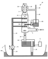
- FIG. 1 is a diagram showing a configuration example of an exhaust gas purification device 1A according to the first embodiment of the present disclosure.
- the exhaust gas purification device 1A is mounted on a ship 2 that generates propulsive force by burning fossil fuels such as heavy oil or coal.
- Examples of the engine that generates propulsive force in the ship 2 include an internal combustion engine such as a gasoline engine or a diesel engine, or an external combustion engine including a turbine and a boiler that supplies steam to the turbine.
- the exhaust gas purification device 1A shown in FIG. 1 is a device that reduces sulfur oxides such as sulfur dioxide contained in exhaust gas generated by combustion of fossil fuels.
- the exhaust gas whose sulfur oxides have been reduced by the exhaust gas purification device 1A is discharged from the exhaust pipe 3 provided in the chimney (funnel) to the external space, specifically, the atmosphere.
- the exhaust gas purification device 1A includes an absorption tower 10, a spray unit 20, a supply pipe 30, a water pipe 32, a drain pipe 34 and a drain pipe 36, a tank 40, and a collection unit 50. , A drain pipe 60, a pump 70, and a swirl 80.
- Exhaust gas generated by burning fossil fuel in the engine of the ship 2 flows into the absorption tower 10 through the exhaust pipe 5.
- the exhaust pipe 5 is an example of an exhaust pipe that communicates the engine of the ship 2, that is, the source of exhaust gas, with the absorption tower 10.
- the absorption tower 10 communicates with the exhaust stack 3.
- the absorption tower 10 may be integrated with the exhaust stack 3.
- the spray unit 20 includes, for example, a plurality of spray nozzles.
- the spraying unit 20 sprays the absorbing liquid for absorbing the sulfur oxide contained in the exhaust gas flowing into the absorbing tower 10 into the absorbing tower 10.
- the ship 2 is a ship navigating in the ocean, and seawater SW is used as an absorbing liquid for absorbing sulfur oxides.
- the pump 70 sucks the seawater SW around the ship 2 and sends the sucked seawater SW to the spray unit 20.
- a supply pipe 30 that opens to the bottom of the ship 2 is connected to the suction port of the pump 70.
- the pump 70 sucks the seawater SW around the ship 2 through the supply pipe 30.
- One end of the water pipe 32 is connected to the discharge port of the pump 70.
- the other end of the water pipe 32 is branched into a plurality of branches, each of which is connected to the spray portion 20.
- the pump 70 sends the seawater SW sucked through the supply pipe 30 to the spray unit 20 via the water pipe 32.
- the spray unit 20 is provided in three stages in the vertical direction of the absorption tower 10.
- the inner diameter of the absorption tower 10 cannot be made sufficiently large, and a sufficient number of spray portions 20 may not be provided in the radial direction of the absorption tower 10. .
- the reason why the spraying portions 20 are provided in three stages in the vertical direction of the absorption tower 10 is that a sufficient number of spraying portions 20 are provided for the entire absorption tower 10 even if the inner diameter of the absorption tower 10 cannot be sufficiently obtained. Is.
- the number of steps in the vertical direction of the spray portion 20 may be one or two. If it is necessary to further reduce the inner diameter of the absorption tower 10, the number of steps in the spray section 20 in the vertical direction may be four or more.
- the absorption liquid sprayed into the absorption tower 10 by the spray unit 20 and used for absorbing sulfur dioxide contained in the exhaust gas is drained from the absorption tower 10 to the tank 40 via the drain pipe 34.
- the liquid drained from the absorption tower 10 via the drain pipe 34 may be referred to as a waste liquid.
- sulfur oxides in the exhaust gas are absorbed by utilizing the alkaline component (HCO 3- ) contained in the seawater SW. More specifically, when the absorption liquid sprayed by the spray unit 20 comes into contact with the exhaust gas, the sulfur oxides contained in the exhaust gas are absorbed into the absorption liquid. Sulfurous acid ion (HSO 3- ) is generated in the absorption liquid in the process of absorbing sulfur oxides.
- the absorbed liquid used for absorbing sulfur oxides is oxidized by contact with a large amount of air in the tank 40, and the sulfite ion in the used absorbed liquid is detoxified as sulfate ion (SO 4-2 ) . ..
- the used absorption liquid that has undergone the oxidation treatment is released into the ocean after adjusting the pH and recovering the dissolved oxygen by neutralization and aeration treatment in the tank 40.
- the chemical reactions of the absorption, oxidation, and neutralization treatments in the exhaust gas purification device 1A are as follows. Absorption : SO 2 + H 2 O ⁇ H + + HSO 3- Oxidation : HSO 3- + (1/2) O 2 ⁇ H + + SO 4 2- Neutralization : HCO 3- + H + ⁇ H 2 O + CO 2 ⁇
- the tank 40 is, for example, a gas seal chamber.
- the waste liquid drained from the drain pipe 34 is stored together with the air.
- a drainage pipe 36 that opens to the bottom of the ship 2 projects into the internal space of the tank 40.
- the waste liquid stored in the tank 40 is discharged to the ocean through the drain pipe 36 after being inspected for pH and dissolved oxygen amount by the water treatment system 4.
- the exhaust gas purification device 1A of the present embodiment is an open-loop type exhaust gas purification device that disposes of the used absorption liquid for absorbing sulfur oxides contained in the exhaust gas without reusing it.
- the sea navigating by the ship 2 equipped with the exhaust gas purification device 1A serves as an external water source for the absorbing liquid.
- a valve that opens and closes under the control of the water treatment system 4 is provided at the upper end of the drainage pipe 36.
- the water treatment system 4 opens the valve at the upper end of the drain pipe 36 when the pH of the liquid stored in the tank 40 and the amount of dissolved oxygen satisfy a predetermined reference value.
- the valve at the upper end of the drain pipe 36 is open, the liquid exceeding the height of the drain pipe 36 protruding into the internal space of the tank 40 is discharged to the ocean outside the ship 2 through the drain pipe 36. ..
- the pH and the amount of dissolved oxygen have predetermined reference values, which are determined according to the sea area in which the ship 2 is navigating.
- the exhaust gas flowing into the absorption tower 10 comes into contact with the absorption liquid sprayed by the spray unit 20, absorbs and removes at least a part of the sulfur oxide contained therein, and then rises toward the exhaust stack 3.
- the exhaust gas in which at least a part of the sulfur oxide is absorbed is referred to as a treated exhaust gas.
- the swirl 80 is a guide blade that applies centrifugal force to the treated exhaust gas rising from the absorption tower 10 toward the exhaust stack 3.
- the swirl 80 is provided at the boundary between the absorption tower 10 and the exhaust stack 3. That is, in the present embodiment, the portion below the swirl 80 is the absorption tower 10, and the portion above the swirl 80 is the exhaust stack 3.
- the treated exhaust gas is given centrifugal force by rising along the swirl 80, and rises along the inner surface of the exhaust stack 3.
- the treated exhaust gas rising along the inner surface of the exhaust stack 3 may be accompanied by droplets of an unused absorption liquid or a used absorption liquid. ..
- the collecting unit 50 is for separating the droplets from the treated exhaust gas accompanying the droplets. As shown in FIG. 1, in the present embodiment, the collecting portion 50 is provided at the upper end portion of the exhaust stack 3, but may be provided at a position below the upper end portion of the exhaust stack 3 and above the swirl 80.
- the collecting unit 50 has an opening that opens on the inner surface of the exhaust gas cylinder 3, and collects droplets that rise along the inner surface of the exhaust gas cylinder 3 together with the treated exhaust gas through the opening portion.
- the drain pipe 60 has a first end connected to the supply pipe 30 and a second end connected to the collection unit 50. As shown in FIG. 1, the supply pipe 30 upstream of the suction port of the pump 70 and the collection unit 50 communicate with each other via the drain pipe 60. The drain pipe 60 drains the droplets collected by the collecting unit 50 to the supply pipe 30 as drain water. The drain water drained from the drain pipe 60 is sent out to the spray unit 20 via the water supply pipe 32 together with the seawater sucked up by the pump 70 through the supply pipe 30, and is used again as an absorbing liquid.
- the inner diameter of the supply pipe 30 is constant, but the inner diameter of the portion to which the drain pipe 60 is connected may be smaller than the inner diameter of the other portion.
- the seawater in the vicinity of the opening of the drain pipe 60 becomes a high-speed low-pressure fluid, and the supply pipe is supplied from the drain pipe 60. It becomes possible to efficiently draw the drain water into 30, and it is possible to improve the mixing property of the drawn drain water and the seawater.
- the drain water is used again as an absorbing liquid.
- the drain water may contain an unused absorbing liquid, and the unused alkaline component contained in the drain water is reused for absorbing the sulfur oxide contained in the exhaust gas.
- the utilization efficiency of the alkaline component contained in the absorption liquid is improved.
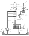
- FIG. 2 is a diagram showing a configuration example of the exhaust gas purification device 1B according to the second embodiment of the present disclosure.
- the exhaust gas purification device 1B of the present embodiment is an open-loop type exhaust gas purification device like the exhaust gas purification device 1A.
- FIG. 2 the same components as those in FIG. 1 are designated by the same reference numerals as those in FIG.
- the first difference is that it has a degassing mechanism 90, a tank 100, a pump 110, and a spray unit 120.
- the second difference is that the collection unit 50 and the tank 100 communicate with each other via the drain pipe 60.
- the degassing mechanism 90 is provided in the upper part of the drain pipe 60, that is, in the vicinity of the connection portion between the drain pipe 60 and the collecting portion 50.
- the degassing mechanism 90 communicates the drain pipe 60 with the external space. Since a gas venting mechanism 90 for communicating the drain pipe 60 to the external space is provided near the connection portion between the drain pipe 60 and the collecting portion 50, in the exhaust gas purification device 1B, the gas venting mechanism is provided from the inlet portion of the drain pipe 60. A flow of exhaust gas toward 90 is generated, and the collection of droplets by the collection unit 50 can be promoted.
- the exhaust gas purifying device 1B of the present embodiment it becomes possible to efficiently collect the droplets by the collecting unit 50 as compared with the exhaust gas purifying device 1A of the first embodiment.
- the exhaust gas purifying device 1A may be provided with the degassing mechanism 90.
- Drain water drained from the drain pipe 60 is stored in the tank 100.
- the pump 110 sucks out the drain water stored in the tank 100 and sends it out to the spray unit 120.
- the pump 110 in the exhaust gas purification device 1B is an example of the second pump in the present disclosure
- the pump 70 is an example of the first pump in the present disclosure.
- the spray unit 120 sprays the drain water sent out from the pump 110 into the absorption tower 10 as an absorption liquid for absorbing sulfur oxides.
- the spray unit 120 is an example of the second spray unit in the present disclosure
- the spray unit 20 is an example of the first spray unit in the present disclosure.
- the exhaust gas purification device 1B has three spray units 20 and one spray unit 120. Then, the spray unit 120 is located on the upstream side of the middle and upper spray units 20 in the flow path of the exhaust gas from the exhaust gas source to the exhaust pipe 3 via the absorption tower 10, that is, on the side closer to the exhaust gas source. It will be provided.
- the exhaust gas rising in the vicinity of the spraying portion 120 passes through the absorption of sulfur oxides by the absorbing liquid sprayed by the lower spraying portion 20. For this reason, the sulfur oxides contained in the exhaust gas rising near the spray unit 120 are reduced by the amount absorbed by the absorption liquid sprayed by the lower spray unit 20, but in the first embodiment, the upper spray is used.
- the exhaust gas containing more sulfur oxides than the exhaust gas rising near the spray portion 20 in the upper stage is sprayed with the drain water as an absorbing liquid by the spray portion 120, so that the drain water remains in the drain water.
- Alkaline components can be effectively used.
- the utilization efficiency of the alkaline component contained in the absorbing liquid is improved in the exhaust gas purification device that absorbs the sulfur oxide contained in the exhaust gas by using the absorbing liquid containing the alkaline component.
- the exhaust gas purifying device 1B of the present embodiment has a degassing mechanism 90 above the drain pipe 60, but the degassing mechanism 90 may be omitted. This is because even if the degassing mechanism 90 is omitted, the efficiency of utilizing the alkaline component contained in the absorbing liquid is still improved.
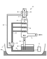
- FIG. 3 is a diagram showing a configuration example of the exhaust gas purification device 1C according to the third embodiment of the present disclosure.
- the exhaust gas purification device 1C of the present embodiment is also an open-loop type exhaust gas purification device like the exhaust gas purification device 1B.
- the same components as those in FIG. 2 are designated by the same reference numerals as those in FIG.
- the difference in the configuration between the exhaust gas purification device 1C and the exhaust gas purification device 1B is that the spray portion 120 is in the path of the exhaust gas from the absorption tower 10 to the exhaust pipe 3. However, it is provided on the upstream side of the three spraying portions 20, specifically, in the exhaust pipe 5 that communicates the exhaust gas generation source and the absorption tower 10.
- the exhaust gas arriving near the spray unit 120 in the exhaust gas purification device 1C contains high-concentration sulfur oxides because the absorption liquid sprayed by the spray unit 20 does not absorb the sulfur oxides.
- the alkaline component remaining in the drain water can be effectively used.
- the exhaust gas purification device that absorbs sulfur oxides contained in the exhaust gas by using the absorbing liquid containing the alkaline component the utilization efficiency of the alkaline component contained in the absorbing liquid is improved.
- the degassing mechanism 90 can be omitted in this embodiment as well.
- the exhaust gas purification device 1A in the first embodiment is an open-loop type exhaust gas purification device that takes in the seawater SW that plays the role of an absorption liquid from the periphery of the ship 2 and discharges the used absorption liquid to the outside of the ship 2. .
- the technical features of the first embodiment may be adopted for a closed-loop type exhaust gas purifying device having a collecting portion and a drain pipe.
- the technical features of the second or third embodiment may be adopted in a closed-loop type exhaust gas purification device having a collecting portion and a drain pipe. This is because even in the closed-loop type exhaust gas purification device, it may not be possible to use up the alkaline component contained in the absorbing liquid.
- FIG. 4 is a diagram showing an example of adoption of the technical features of the first embodiment in a closed-loop type exhaust gas purification device having a collecting portion and a drain pipe.
- the exhaust gas purification device 1D a certain amount of absorbing liquid is stored in the tank 40 in advance.
- the supply pipe 30 is connected to the tank 40.
- the pump 70 sucks the absorbing liquid stored in the tank 40 through the supply pipe 30 and sends it out to the spraying unit 20 via the water pipe 32.
- the exhaust gas purification device 1D shown in FIG. 5 is not provided with the drain pipe 36, and the used absorption liquid returned to the tank 40 is reused as the absorption liquid after being neutralized and aerated.
- the drain water is a tank as in the exhaust gas purification device 1A of the first embodiment. It is used to absorb sulfur oxides together with the water absorbing liquid drawn from 40. Therefore, the alkaline component remaining in the drain water can be used for absorption of sulfur oxides.
- FIG. 5 is a diagram showing an example of adoption of the technical features of the first embodiment in the exhaust gas purification device of the hybrid system.
- the exhaust gas purification device 1E shown in FIG. 5 includes a supply pipe 30a, a supply pipe 30b, a supply pipe 30c, and a switching valve 38.
- the supply pipe 30a opens at the bottom of the ship 2.
- the supply pipe 30b is connected to the tank 40.
- Each of the supply pipe 30a and the supply pipe 30b is connected to the supply pipe 30c via the switching valve 38.
- the supply pipe 30c is connected to the suction port of the pump 70, and the drain pipe 60 is connected to the supply pipe 30c.
- the switching valve 38 is a three-way valve.
- the exhaust gas purification device 1E by switching the switching valve 38, either one of the supply pipe 30a and the supply pipe 30b communicates with the suction port of the pump 70 via the supply pipe 30c.
- the exhaust gas purification device 1E functions as an open-loop type exhaust gas purification device.
- the exhaust gas purification device 1E functions as a closed-loop type exhaust gas purification device.
- the exhaust gas can be purified by the open loop type in the sea area where the drainage regulation to the ocean is loose, while the exhaust gas can be purified by the closed loop type in the sea area where the drainage regulation is strict.
- the open ocean is an example of a sea area where drainage regulations are loose.
- a coastal sea area is an example of a sea area where drainage regulations are strict.
- the exhaust gas purification device 1E shown in FIG. 5 may be modified to have a configuration in which the supply pipe 30b is connected to the supply pipe 30a via a switching valve. This configuration may be modified to a configuration in which a second pump separate from the pump 70 is further provided, and seawater sucked by the second pump is injected into the tank 40 via the supply pipe 30b.
- a configuration in which the supply pipe 30b is connected to the water supply pipe 32 is also conceivable, but in the configuration in which the supply pipe 30b is connected to the water supply pipe 32, a pump for delivering the absorption liquid from the supply pipe 30b to the water supply pipe 32 is provided in the supply pipe 30b. Is required.
- the ship 2 in each of the above embodiments is a ship navigating in the ocean, but may be a vessel navigating in a freshwater area.
- sodium hydroxide, magnesium hydroxide, or the like may be added to the water sucked from the periphery of the ship 2 to replenish the alkaline component.
- the absorption liquid in the present disclosure is not limited to seawater, and may be an alkaline aqueous solution containing an alkaline component.
- the alkaline component is not limited to HCO 3- .
- the tank 100 and the pump 110 are provided at the same height, but the tank 100 may be provided at a position higher than the pump 110. This is to reduce the load on the pump 110 when the drain water is sucked out from the tank 100.
- the drain water collected by the collecting unit 50 is stored in the tank 100, and the drain water stored in the tank 100 is sucked out by the pump 110 and sent out to the spraying unit 120. ..
- the tank 100 and the pump 110 may be omitted, and the collection unit 50 and the spray unit 120 may be communicated with each other via the drain pipe 60. In short, the drain water collected by the collecting unit 50 may be sprayed onto the spraying unit 120.
- One aspect of the exhaust gas purification apparatus of the present disclosure includes an absorption tower, a spray section, a pump, a collection section, and a drain pipe.
- Exhaust gas generated by the combustion of fossil fuels flows into the absorption tower.
- the absorption tower communicates with the exhaust pipe that discharges the exhaust gas with reduced sulfur oxides to the external space.
- the spraying unit sprays an absorbing liquid containing an alkaline component for absorbing sulfur oxides into the absorption tower.
- the pump sends the absorbing liquid to the spraying part.
- the collecting unit is provided in the exhaust stack to collect the droplets accompanying the exhaust gas rising from the absorption tower toward the exhaust stack.
- the drain pipe communicates the supply pipe upstream of the suction port of the pump with the collection part.
- the drain pipe uses the droplets collected by the collection unit as drain water and drains them to the supply pipe upstream of the suction port of the pump. According to the exhaust gas purification device of this embodiment, the utilization efficiency of the alkaline component contained in the absorbing liquid is improved.
- the inner diameter of the portion of the supply pipe upstream of the suction port of the pump to which the drain pipe is connected may be smaller than the inner diameter of the other portion of the supply pipe. According to the exhaust gas purification device of this embodiment, the drain water can be efficiently drawn into the supply pipe, and the mixing property of the drawn drain water and the absorbing liquid can be improved.
- a more preferable embodiment of the exhaust gas purification device includes a first drainage pipe, a tank, and a second drainage pipe.
- the first drain pipe drains the absorption liquid sprayed into the absorption tower by the spray unit from the absorption tower.
- the drainage pipe 34 in the first embodiment is an example of the first drainage pipe.
- the tank stores the absorbing liquid drained from the first drain pipe.
- the tank corresponds to the tank 40 in each of the above embodiments.
- the second drain pipe drains the absorbed liquid stored in the tank to an external water source.
- the drainage pipe 36 in the first embodiment is an example of the second drainage pipe.
- the exhaust gas purification device of this embodiment water sucked from an external water source by a pump is used as the absorption liquid, and the used absorption liquid is stored in the tank and then drained through the second drain pipe. That is, the exhaust gas purification device of this embodiment is an open loop type. As described above, according to this aspect, in the open loop type exhaust gas purification device that absorbs the sulfur oxide contained in the exhaust gas by using the absorbing liquid containing the alkaline component, the utilization efficiency of the alkaline component contained in the absorbing liquid is improved. do.
- the exhaust gas purification device includes a drain pipe for draining the absorption liquid sprayed into the absorption tower by the spray unit from the absorption tower, and a tank for storing the absorption liquid drained from the drain pipe.
- the pump sucks the absorbed liquid stored in the tank and sends it out to the spraying part.
- the exhaust gas purification device of this embodiment is a closed loop type.
- the closed-loop type exhaust gas purification device that absorbs sulfur oxides contained in the exhaust gas by using the absorbing liquid containing the alkaline component, the utilization efficiency of the alkaline component contained in the absorbing liquid is improved. do.
- the exhaust gas purification device of another aspect of the present disclosure includes an absorption tower, one or more first spraying parts, a first pump, a collecting part, and a second spraying part.
- Exhaust gas generated by the combustion of fossil fuels flows into the absorption tower.
- the absorption tower communicates with the exhaust pipe that discharges the exhaust gas with reduced sulfur oxides to the external space.
- One or a plurality of first spray units spray an absorption liquid containing an alkaline component for absorbing sulfur oxides into the absorption tower.
- the first pump sends the absorption liquid to the one or a plurality of first spraying portions.
- the collecting unit is provided in the exhaust stack in order to collect droplets accompanying the exhaust gas rising from the absorption tower toward the exhaust stack.
- the second spray unit is located upstream of at least one of the one or a plurality of first spray units in the flow path of the exhaust gas from the source of the exhaust gas to the exhaust stack via the absorption tower. Be placed.
- the second spraying unit sprays the droplets collected by the collecting unit as drain water.
- the alkaline component remaining in the drain water can be effectively used, so that the utilization efficiency of the alkaline component is improved.
- the exhaust gas purification device includes a drain pipe for draining the drain water, a tank for storing the drain water drained from the drain pipe, and the drain water stored in the tank to the two spraying portions.
- a second pump to deliver may be provided.
- the second spray unit may be arranged inside the absorption tower.
- the exhaust gas purifying device of another preferred embodiment includes an exhaust pipe that communicates the exhaust gas source and the absorption tower, and the second spraying portion may be installed in the exhaust pipe.
- Exhaust gas purification device 2 ... Ship, 3 ... Exhaust pipe, 4 ... Water treatment system, 5 ... Exhaust pipe, 10 ... Absorption tower, 20, 120 ... Spray part, 30 ... Supply pipe, 32 ... Water pipe, 34, 36 ... Drain pipe, 40, 100 ... Tank, 50 ... Collection part, 60 ... Drain pipe, 70, 110 ... Pump, 80 ... Swala, 90 ... Degassing mechanism.
Landscapes
- Chemical & Material Sciences (AREA)
- Engineering & Computer Science (AREA)
- Analytical Chemistry (AREA)
- General Chemical & Material Sciences (AREA)
- Oil, Petroleum & Natural Gas (AREA)
- Chemical Kinetics & Catalysis (AREA)
- Environmental & Geological Engineering (AREA)
- Health & Medical Sciences (AREA)
- Biomedical Technology (AREA)
- Combustion & Propulsion (AREA)
- Treating Waste Gases (AREA)
- Gas Separation By Absorption (AREA)
Abstract
Description
図1は、本開示の第1実施形態に係る排ガス浄化装置1Aの構成例を示す図である。排ガス浄化装置1Aは、重油又は石炭等の化石燃料を燃焼させて推進力を発生させる船舶2に搭載される。船舶2において推進力を発生される機関としては、ガソリンエンジン又はディーゼルエンジン等の内燃機関、或いはタービンとタービンに蒸気を供給するボイラとを含む外燃機関が挙げられる。図1に示す排ガス浄化装置1Aは、化石燃料の燃焼により発生する排ガスに含まれる二酸化硫黄等の硫黄酸化物を低減させる装置である。排ガス浄化装置1Aにより硫黄酸化物を低減済の排ガスは、煙突(funnel)に設けられる排気筒3から、外部空間、具体的には大気中、へ放出される。
吸収:SO2+H2O→H++HSO3 -
酸化:HSO3 -+(1/2)O2→H++SO4 2-
中和:HCO3 -+H+→H2O+CO2↑
図2は、本開示の第2実施形態に係る排ガス浄化装置1Bの構成例を示す図である。本実施形態の排ガス浄化装置1Bは、排ガス浄化装置1Aと同様にオープンループ型の排ガス浄化装置である。図2では、図1におけるものと同じ構成要素には図1におけるものと同一の符号が付されている。図2と図1とを対比すれば明らかなように、排ガス浄化装置1Bと排ガス浄化装置1Aとの構成の相違点は以下の2点である。第1の相違点は、ガス抜き機構90、タンク100、ポンプ110、及び噴霧部120を有する点である。第2の相違点は、ドレイン管60を介して捕集部50とタンク100とが連通している点である。
図3は、本開示の第3実施形態に係る排ガス浄化装置1Cの構成例を示す図である。本実施形態の排ガス浄化装置1Cも、排ガス浄化装置1Bと同様にオープンループ型の排ガス浄化装置である。図3では、図2におけるものと同じ構成要素には図2におけるものと同一の符号が付されている。図3と図2とを対比すれば明らかなように、排ガス浄化装置1Cと排ガス浄化装置1Bとの構成の相違点は、吸収塔10を経て排気筒3に至る排ガスの経路において、噴霧部120が、3つの噴霧部20よりも上流側、具体的には、排ガスの発生源と吸収塔10とを連通させる排気管5に設けられている点である。
以上の各実施態様は多様に変形され得る。具体的な変形の態様を以下に例示する。以下の例示から任意に選択された2以上の態様は相矛盾しない限り適宜に併合され得る。
上記第1実施形態における排ガス浄化装置1Aは、吸収液の役割を果たす海水SWを船舶2の周囲から取り込み、使用済み吸収液を船舶2の外部へ放出するオープンループ型の排ガス浄化装置であった。しかし、捕集部及びドレイン管を有するクローズドループ型の排ガス浄化装置に第1実施形態の技術的特徴を採用してもよい。同様に、第2実施形態又は第3実施形態の技術的特徴を、捕集部及びドレイン管を有するクローズドループ型の排ガス浄化装置に採用してもよい。クローズドループ型の排ガス浄化装置においても、吸収液に含まれるアルカリ成分を使いきることができない場合があることは同様だからである。
上記各実施形態における船舶2は海洋を航行する船舶であったが、淡水域を航行する船舶であってもよい。この場合、船舶2の周囲から吸引した水に水酸化ナトリウム又は水酸化マグネシウム等を添加してアルカリ成分を補充すればよい。つまり、本開示における吸収液は海水には限定されず、アルカリ成分を含むアルカリ水溶液であればよい。また、アルカリ成分もHCO3 -には限定されない。
上記第2及び第3実施形態では、タンク100と、ポンプ110とが同じ高さの位置に設けられていたが、タンク100はポンプ110よりも高い位置に設けられていてもよい。タンク100からドレイン水を吸い出す際のポンプ110の負荷を軽減するためである。また、上記第2及び第3実施形態では、捕集部50により捕集されるドレイン水をタンク100に貯留し、タンク100に貯留されるドレイン水をポンプ110により吸い出して噴霧部120へ送り出した。しかし、タンク100及びポンプ110を省略し、捕集部50と噴霧部120とをドレイン管60を介して連通させてもよい。要は、捕集部50により捕集されるドレイン水を噴霧部120に噴霧させる態様であればよい。
上記各実施形態では、化石燃料を燃焼させて推進力を発生させる船舶に搭載される排ガス浄化装置への本開示の適用例を説明した。しかし、本開示の排ガス浄化装置を、火力発電所又は製鉄所等の陸上の固定施設、内燃機関を用いた発電機、或いは内燃機関或いは外燃機関により推進力を発生させる車両において化石燃料を燃焼させることにより発生する排ガスの浄化に本開示を適用してもよい。また、上記各実施形態におけるスワラ80は本開示の必須構成要素ではなく、省略されてもよい。
本開示の排ガス浄化装置の一態様は、吸収塔と、噴霧部と、ポンプと、捕集部と、ドレイン管と、を備える。吸収塔には、化石燃料の燃焼により発生する排ガスが流入する。吸収塔は、硫黄酸化物を低減済の排ガスを外部空間に放出する排気筒に連通する。噴霧部は、硫黄酸化物を吸収するためのアルカリ成分を含む吸収液を吸収塔内に噴霧する。ポンプは、噴霧部へ吸収液を送り出す。捕集部は、吸収塔から排気筒に向かって上昇する排ガスに同伴する液滴を捕集するために排気筒に設けられる。ドレイン管は、ポンプの吸引口よりも上流の供給管と捕集部とを連通させる。ドレイン管は、捕集部により捕集される液滴をドレイン水として、ポンプの吸引口よりも上流の供給管へ排水する。本態様の排ガス浄化装置によれば、吸収液に含まれるアルカリ成分の利用効率が向上する。
Claims (8)
- 排気筒に連通し、化石燃料の燃焼により発生する排ガスが流入する吸収塔と、
硫黄酸化物を吸収するためのアルカリ成分を含む吸収液を前記吸収塔内に噴霧する噴霧部と、
前記噴霧部へ前記吸収液を送り出すポンプと、
前記吸収塔から前記排気筒に向かって上昇する排ガスに同伴する液滴を捕集するために前記排気筒に設けられる捕集部と、
第1端および第2端を有し、前記第1端が前記ポンプの吸引口よりも上流の供給管に接続されるとともに前記第2端が前記捕集部に接続されることにより、前記供給管と前記捕集部とが連通し、前記捕集部により捕集される液滴をドレイン水として前記吸収液の流路へ排水するドレイン管と、
を備える排ガス浄化装置。 - 前記流路における前記ドレイン管が接続される部分の内径は、前記流路における他の部分の内径よりも小さい、ことを特徴とする請求項1に記載の排ガス浄化装置。
- 前記噴霧部により前記吸収塔内に噴霧される吸収液を前記吸収塔から排水する第1排水管と、
前記第1排水管から排水される吸収液を貯留するタンクと、
前記タンクに貯留される吸収液を外部水源へ排水する第2排水管と、を備え、
前記ポンプにより前記噴霧部へ送り出される吸収液には、前記ポンプにより前記外部水源から吸引される水が利用される、ことを特徴とする請求項1又は請求項2に記載の排ガス浄化装置。 - 前記噴霧部により前記吸収塔内に噴霧される吸収液を前記吸収塔から排水する排水管と、
前記排水管から排水される吸収液を貯留するタンクと、を備え、
前記ポンプは、前記タンクに貯留される吸収液を吸引し、前記噴霧部へ送り出す、ことを特徴とする請求項1又は請求項2に記載の排ガス浄化装置。 - 排気筒に連通し、化石燃料の燃焼により発生する排ガスが流入する吸収塔と、
硫黄酸化物を吸収するためのアルカリ成分を含む吸収液を前記吸収塔内に噴霧する1又は複数の第1噴霧部と、
前記1又は複数の第1噴霧部へ前記吸収液を送り出す第1ポンプと、
前記吸収塔から前記排気筒に向かって上昇する排ガスに同伴する液滴を捕集するために前記排気筒に設けられる捕集部と、
前記排ガスの発生源から前記吸収塔を経由して前記排気筒に至る前記排ガスの流路において前記1又は複数の第1噴霧部のうちの少なくとも1つよりも上流側に配置され、
前記捕集部により捕集される液滴をドレイン水として噴霧する第2噴霧部と、
を備える排ガス浄化装置。 - 前記ドレイン水を排水するドレイン管と、
前記ドレイン管から排水される前記ドレイン水を貯留するタンクと、
前記タンクに貯留される前記ドレイン水を前記第2噴霧部へ送り出す第2ポンプと、
を備える請求項5に記載の排ガス浄化装置。 - 前記第2噴霧部は、前記吸収塔の内部に配置されることを特徴とする請求項5又は請求項6に記載の排ガス浄化装置。
- 前記排ガスの発生源と前記吸収塔とを連通させる排気管を備え、
前記第2噴霧部は前記排気管に設置される、
ことを特徴とする請求項5又は請求項6に記載の排ガス浄化装置。
Priority Applications (3)
| Application Number | Priority Date | Filing Date | Title |
|---|---|---|---|
| CN202180011070.5A CN115038507A (zh) | 2020-08-24 | 2021-06-30 | 排气净化装置 |
| JP2022545491A JP7323077B2 (ja) | 2020-08-24 | 2021-06-30 | 排ガス浄化装置 |
| KR1020227025657A KR20220112302A (ko) | 2020-08-24 | 2021-06-30 | 배기가스 정화 장치 |
Applications Claiming Priority (2)
| Application Number | Priority Date | Filing Date | Title |
|---|---|---|---|
| JP2020-141227 | 2020-08-24 | ||
| JP2020141227 | 2020-08-24 |
Publications (1)
| Publication Number | Publication Date |
|---|---|
| WO2022044537A1 true WO2022044537A1 (ja) | 2022-03-03 |
Family
ID=80353122
Family Applications (1)
| Application Number | Title | Priority Date | Filing Date |
|---|---|---|---|
| PCT/JP2021/024749 Ceased WO2022044537A1 (ja) | 2020-08-24 | 2021-06-30 | 排ガス浄化装置 |
Country Status (4)
| Country | Link |
|---|---|
| JP (1) | JP7323077B2 (ja) |
| KR (1) | KR20220112302A (ja) |
| CN (1) | CN115038507A (ja) |
| WO (1) | WO2022044537A1 (ja) |
Citations (4)
| Publication number | Priority date | Publication date | Assignee | Title |
|---|---|---|---|---|
| WO1994023826A1 (fr) * | 1993-04-09 | 1994-10-27 | Babcock-Hitachi Kabushiki Kaisha | Dispositif de desulfuration a voie humide d'effluents gazeux |
| JPH11128671A (ja) * | 1997-11-05 | 1999-05-18 | Mitsubishi Heavy Ind Ltd | 湿式排煙脱硫装置 |
| JPH11151426A (ja) * | 1997-11-19 | 1999-06-08 | Ishikawajima Harima Heavy Ind Co Ltd | 煙突一体型排煙脱硫装置 |
| WO2014098081A1 (ja) * | 2012-12-19 | 2014-06-26 | 富士電機株式会社 | 排ガス処理装置 |
Family Cites Families (6)
| Publication number | Priority date | Publication date | Assignee | Title |
|---|---|---|---|---|
| EP1366796A3 (en) * | 1997-11-11 | 2004-01-07 | Mitsubishi Heavy Industries, Ltd. | A wet gas processing method and the apparatus using the same |
| FR2894156B1 (fr) * | 2005-12-02 | 2008-02-22 | Otv Sa | Dispositif de traitement d'un effluent gazeux charge en composes odorants a l'aide d'un maillage tridimensionnel, installation et procede correspondants |
| CN107321155A (zh) * | 2017-06-21 | 2017-11-07 | 宜昌聚龙环保科技有限公司 | 一种用于氮氧化物的吸收装置 |
| CN206996233U (zh) * | 2017-07-07 | 2018-02-13 | 金川集团股份有限公司 | 一种塔囱一体的烟气处理装置 |
| CN108722163B (zh) * | 2017-09-07 | 2019-06-07 | 江苏新世纪江南环保股份有限公司 | 一种氨法脱硫控制吸收过程气溶胶产生的方法 |
| CN210814668U (zh) * | 2019-09-11 | 2020-06-23 | 宜昌汇富硅材料有限公司 | 一种气相法白炭黑生产装置的尾气处理系统 |
-
2021
- 2021-06-30 KR KR1020227025657A patent/KR20220112302A/ko active Pending
- 2021-06-30 WO PCT/JP2021/024749 patent/WO2022044537A1/ja not_active Ceased
- 2021-06-30 CN CN202180011070.5A patent/CN115038507A/zh active Pending
- 2021-06-30 JP JP2022545491A patent/JP7323077B2/ja active Active
Patent Citations (4)
| Publication number | Priority date | Publication date | Assignee | Title |
|---|---|---|---|---|
| WO1994023826A1 (fr) * | 1993-04-09 | 1994-10-27 | Babcock-Hitachi Kabushiki Kaisha | Dispositif de desulfuration a voie humide d'effluents gazeux |
| JPH11128671A (ja) * | 1997-11-05 | 1999-05-18 | Mitsubishi Heavy Ind Ltd | 湿式排煙脱硫装置 |
| JPH11151426A (ja) * | 1997-11-19 | 1999-06-08 | Ishikawajima Harima Heavy Ind Co Ltd | 煙突一体型排煙脱硫装置 |
| WO2014098081A1 (ja) * | 2012-12-19 | 2014-06-26 | 富士電機株式会社 | 排ガス処理装置 |
Also Published As
| Publication number | Publication date |
|---|---|
| CN115038507A (zh) | 2022-09-09 |
| JP7323077B2 (ja) | 2023-08-08 |
| KR20220112302A (ko) | 2022-08-10 |
| JPWO2022044537A1 (ja) | 2022-03-03 |
Similar Documents
| Publication | Publication Date | Title |
|---|---|---|
| US10563553B2 (en) | System and method for reducing the amount of sulfur oxides in exhaust gas | |
| CN116608059B (zh) | 排液处理装置 | |
| KR102415706B1 (ko) | 선박의 온실가스 배출 저감장치 및 동 장치 구비한 선박 | |
| JP6351183B2 (ja) | 高濃度に硫黄成分を含有する重油等の低質燃料を使用する船舶用ディーゼルエンジンの排気ガス浄化装置 | |
| CN116507795A (zh) | 船舶的温室气体减排装置及具备其的船舶 | |
| JP6663481B2 (ja) | 船舶の船内でガスをクリーニングするためのインラインデュアルウォータースクラバーおよび方法 | |
| KR102299077B1 (ko) | 배기가스 처리장치 | |
| WO2014156985A1 (ja) | 海水排煙脱硫装置とその運用方法 | |
| KR102231449B1 (ko) | 선박의 온실가스 배출 저감장치 및 이를 구비한 선박 | |
| CN116490678B (zh) | 船舶的温室气体减排装置及具备其的船舶 | |
| JP4381064B2 (ja) | 排ガス処理装置および処理方法 | |
| CN115485465B (zh) | 船舶的温室气体减排装置及具备其的船舶 | |
| KR102231467B1 (ko) | 선박의 온실가스 배출 저감장치 및 이를 구비한 선박 | |
| KR102724175B1 (ko) | 선박의 온실가스 배출 저감장치 및 이를 구비한 선박 | |
| WO2022044537A1 (ja) | 排ガス浄化装置 | |
| JP7323076B2 (ja) | 排ガス浄化装置 | |
| KR20230016692A (ko) | 사이클론식의 배기가스 정화 장치 | |
| EP3533977B1 (en) | Device for discharging exhaust gas | |
| TWI901365B (zh) | 兼具多功能實質環保效益的船舶專用脫硫系統及其裝置 | |
| KR102038944B1 (ko) | 향상된 공간활용도를 가진 하이브리드형 배기가스 처리 시스템 | |
| JP2023544056A (ja) | 船舶の温室効果ガス排出低減装置及びそれを具備した船舶 | |
| JP3525369B2 (ja) | スプレ式吸収塔と排煙脱硫装置 | |
| JP2023544055A (ja) | 船舶の温室効果ガス排出低減装置及び同装置を具備した船舶 | |
| KR102364186B1 (ko) | 선박용 배기가스 정화방법과 정화장치 및 이를 구비하는 선박 | |
| TW202612775A (zh) | 兼具多功能實質環保效益的船舶專用脫硫系統及其裝置 |
Legal Events
| Date | Code | Title | Description |
|---|---|---|---|
| 121 | Ep: the epo has been informed by wipo that ep was designated in this application |
Ref document number: 21860967 Country of ref document: EP Kind code of ref document: A1 |
|
| ENP | Entry into the national phase |
Ref document number: 20227025657 Country of ref document: KR Kind code of ref document: A |
|
| ENP | Entry into the national phase |
Ref document number: 2022545491 Country of ref document: JP Kind code of ref document: A |
|
| NENP | Non-entry into the national phase |
Ref country code: DE |
|
| 122 | Ep: pct application non-entry in european phase |
Ref document number: 21860967 Country of ref document: EP Kind code of ref document: A1 |