WO2022044536A1 - Exhaust gas purifying device - Google Patents
Exhaust gas purifying device Download PDFInfo
- Publication number
- WO2022044536A1 WO2022044536A1 PCT/JP2021/024748 JP2021024748W WO2022044536A1 WO 2022044536 A1 WO2022044536 A1 WO 2022044536A1 JP 2021024748 W JP2021024748 W JP 2021024748W WO 2022044536 A1 WO2022044536 A1 WO 2022044536A1
- Authority
- WO
- WIPO (PCT)
- Prior art keywords
- exhaust gas
- purification device
- drain pipe
- gas purification
- absorption tower
- Prior art date
Links
Images


Classifications
-
- B—PERFORMING OPERATIONS; TRANSPORTING
- B01—PHYSICAL OR CHEMICAL PROCESSES OR APPARATUS IN GENERAL
- B01D—SEPARATION
- B01D53/00—Separation of gases or vapours; Recovering vapours of volatile solvents from gases; Chemical or biological purification of waste gases, e.g. engine exhaust gases, smoke, fumes, flue gases, aerosols
- B01D53/14—Separation of gases or vapours; Recovering vapours of volatile solvents from gases; Chemical or biological purification of waste gases, e.g. engine exhaust gases, smoke, fumes, flue gases, aerosols by absorption
- B01D53/18—Absorbing units; Liquid distributors therefor
-
- B—PERFORMING OPERATIONS; TRANSPORTING
- B01—PHYSICAL OR CHEMICAL PROCESSES OR APPARATUS IN GENERAL
- B01D—SEPARATION
- B01D47/00—Separating dispersed particles from gases, air or vapours by liquid as separating agent
- B01D47/06—Spray cleaning
- B01D47/063—Spray cleaning with two or more jets impinging against each other
-
- B—PERFORMING OPERATIONS; TRANSPORTING
- B01—PHYSICAL OR CHEMICAL PROCESSES OR APPARATUS IN GENERAL
- B01D—SEPARATION
- B01D47/00—Separating dispersed particles from gases, air or vapours by liquid as separating agent
- B01D47/12—Washers with plural different washing sections
-
- B—PERFORMING OPERATIONS; TRANSPORTING
- B01—PHYSICAL OR CHEMICAL PROCESSES OR APPARATUS IN GENERAL
- B01D—SEPARATION
- B01D53/00—Separation of gases or vapours; Recovering vapours of volatile solvents from gases; Chemical or biological purification of waste gases, e.g. engine exhaust gases, smoke, fumes, flue gases, aerosols
- B01D53/14—Separation of gases or vapours; Recovering vapours of volatile solvents from gases; Chemical or biological purification of waste gases, e.g. engine exhaust gases, smoke, fumes, flue gases, aerosols by absorption
-
- B—PERFORMING OPERATIONS; TRANSPORTING
- B01—PHYSICAL OR CHEMICAL PROCESSES OR APPARATUS IN GENERAL
- B01D—SEPARATION
- B01D53/00—Separation of gases or vapours; Recovering vapours of volatile solvents from gases; Chemical or biological purification of waste gases, e.g. engine exhaust gases, smoke, fumes, flue gases, aerosols
- B01D53/34—Chemical or biological purification of waste gases
- B01D53/46—Removing components of defined structure
- B01D53/48—Sulfur compounds
- B01D53/50—Sulfur oxides
-
- B—PERFORMING OPERATIONS; TRANSPORTING
- B01—PHYSICAL OR CHEMICAL PROCESSES OR APPARATUS IN GENERAL
- B01D—SEPARATION
- B01D53/00—Separation of gases or vapours; Recovering vapours of volatile solvents from gases; Chemical or biological purification of waste gases, e.g. engine exhaust gases, smoke, fumes, flue gases, aerosols
- B01D53/34—Chemical or biological purification of waste gases
- B01D53/74—General processes for purification of waste gases; Apparatus or devices specially adapted therefor
- B01D53/77—Liquid phase processes
- B01D53/78—Liquid phase processes with gas-liquid contact
-
- B—PERFORMING OPERATIONS; TRANSPORTING
- B01—PHYSICAL OR CHEMICAL PROCESSES OR APPARATUS IN GENERAL
- B01D—SEPARATION
- B01D2252/00—Absorbents, i.e. solvents and liquid materials for gas absorption
- B01D2252/10—Inorganic absorbents
- B01D2252/103—Water
- B01D2252/1035—Sea water
-
- B—PERFORMING OPERATIONS; TRANSPORTING
- B01—PHYSICAL OR CHEMICAL PROCESSES OR APPARATUS IN GENERAL
- B01D—SEPARATION
- B01D2257/00—Components to be removed
- B01D2257/30—Sulfur compounds
- B01D2257/302—Sulfur oxides
-
- B—PERFORMING OPERATIONS; TRANSPORTING
- B01—PHYSICAL OR CHEMICAL PROCESSES OR APPARATUS IN GENERAL
- B01D—SEPARATION
- B01D2258/00—Sources of waste gases
- B01D2258/01—Engine exhaust gases
Definitions
- the present disclosure relates to an exhaust gas purification device that reduces sulfur oxides contained in exhaust gas generated by combustion of fossil fuels such as coal or heavy oil.
- An example of an exhaust gas purification device that reduces sulfur oxides contained in exhaust gas generated by combustion of fossil fuels is a device that uses an absorbing liquid containing an alkaline component.
- Exhaust gas purification devices that use an absorbent liquid are roughly classified into an open loop type and a closed loop type.
- the open-loop type exhaust gas purification device the absorbed liquid used for absorbing sulfur oxides is stored in a tank or the like and then discarded.
- the used absorption liquid is stored in a tank or the like and reused as the absorption liquid.
- Patent Document 1 discloses a closed-loop type exhaust gas purification device.
- the exhaust gas purification device disclosed in Patent Document 1 has an absorption tower integrated with a chimney. Inside the absorption tower, a spray nozzle that sprays the absorption liquid onto the exhaust gas flowing into the absorption tower is arranged. On the inner surface of the upper part of the absorption tower, guide blades that give centrifugal force to the exhaust gas rising toward the chimney are arranged. Exhaust gas centrifugally applied by the guide blades rises along the inner surface of the chimney. Droplets may accompany the exhaust gas rising along the inner surface of the chimney. On the inner surface of the upper part of the chimney, a scraping portion for collecting droplets accompanying the exhaust gas is arranged. A drain pipe that returns the droplets into the absorption tower is connected to the scraping portion, and the droplets that are returned into the absorption tower via the drain pipe are used again as the absorbing liquid.
- the present disclosure has been made in view of the above-described problems, and the collection of droplets is not hindered in the exhaust gas purification device having a configuration for collecting droplets accompanying the exhaust gas rising toward the exhaust stack.
- the purpose is to provide the technology to do so.
- the exhaust gas purifying device of the present disclosure communicates with an exhaust pipe, and has an absorption tower through which exhaust gas generated by combustion of fossil fuel flows in and an absorption tower for absorbing sulfur oxide.
- a collection section provided in the exhaust stack for collecting droplets accompanying the exhaust gas rising toward the exhaust stack, and a drain that communicates with the drain pipe and is collected by the collection portion. It is provided with a drain pipe for draining as water.
- the exhaust gas purification device of another aspect of the present disclosure communicates with the exhaust stack and absorbs the absorption tower in which the exhaust gas generated by the combustion of fossil fuel flows in and the sulfur oxide.
- the collecting portion provided in the exhaust stack for collecting the droplets accompanying the exhaust gas rising from the absorption tower toward the exhaust stack, and the droplets collected by the collecting portion are drain water.
- a drain pipe for draining water to the tank and a degassing mechanism for communicating the tank with the external space are provided.
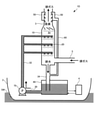
- FIG. 1 is a diagram showing a configuration example of an exhaust gas purification device 1A according to the first embodiment of the present disclosure.
- the exhaust gas purification device 1A is mounted on a ship 2 that generates propulsive force by burning fossil fuels such as heavy oil or coal.
- Examples of the engine that generates propulsive force in the ship 2 include an internal combustion engine such as a gasoline engine or a diesel engine, or an external combustion engine including a turbine and a boiler that supplies steam to the turbine.
- the exhaust gas purification device 1A shown in FIG. 1 is a device that reduces sulfur oxides such as sulfur dioxide contained in exhaust gas generated by combustion of fossil fuels.
- the exhaust gas whose sulfur oxides have been reduced by the exhaust gas purification device 1A is discharged from the exhaust pipe 3 provided in the chimney (funnel) to the external space, specifically, the atmosphere.
- the exhaust gas purification device 1A includes an absorption tower 10, a spray unit 20, a supply pipe 30, a water pipe 32, a drain pipe 34 and a drain pipe 36, a tank 40, and a collection unit 50. , A drain pipe 60, a pump 70, and a swirl 80.
- Exhaust gas generated by burning fossil fuel in the engine of the ship 2 flows into the absorption tower 10 through the exhaust pipe 5.
- the exhaust pipe 5 is an example of an exhaust pipe that communicates the engine of the ship 2, that is, the source of exhaust gas, with the absorption tower 10.
- the absorption tower 10 communicates with the exhaust stack 3.
- the absorption tower 10 may be integrated with the exhaust stack 3.
- the spray unit 20 includes, for example, a plurality of spray nozzles.
- the spraying unit 20 sprays the absorbing liquid for absorbing the sulfur oxide contained in the exhaust gas flowing into the absorbing tower 10 into the absorbing tower 10.
- the ship 2 is a ship navigating in the ocean, and seawater SW is used as an absorbing liquid for absorbing sulfur oxides.
- the pump 70 sucks the seawater SW around the ship 2 and sends the sucked seawater SW to the spray unit 20.
- a supply pipe 30 that opens to the bottom of the ship 2 is connected to the suction port of the pump 70.
- the pump 70 sucks the seawater SW around the ship 2 through the supply pipe 30.
- One end of the water pipe 32 is connected to the discharge port of the pump 70.
- the other end of the water pipe 32 is branched into a plurality of branches, each of which is connected to the spray portion 20.
- the pump 70 sends the seawater SW sucked through the supply pipe 30 to the spray unit 20 via the water pipe 32.
- the spray unit 20 is provided in three stages in the vertical direction of the absorption tower 10.
- the inner diameter of the absorption tower 10 cannot be made sufficiently large, and a sufficient number of spray portions 20 may not be provided in the radial direction of the absorption tower 10. .
- the reason why the spraying portions 20 are provided in three stages in the vertical direction of the absorption tower 10 is that a sufficient number of spraying portions 20 are provided for the entire absorption tower 10 even if the inner diameter of the absorption tower 10 cannot be sufficiently obtained. Is.
- the number of steps in the vertical direction of the spray portion 20 may be one or two. If it is necessary to further reduce the inner diameter of the absorption tower 10, the number of steps in the spray section 20 in the vertical direction may be four or more.
- the absorption liquid sprayed into the absorption tower 10 by the spray unit 20 and used for absorbing sulfur dioxide contained in the exhaust gas is drained from the absorption tower 10 to the tank 40 via the drain pipe 34.
- the liquid drained from the absorption tower 10 via the drain pipe 34 may be referred to as a waste liquid.
- sulfur oxides in the exhaust gas are absorbed by utilizing the alkaline component (HCO 3- ) contained in the seawater SW. More specifically, when the absorption liquid sprayed by the spray unit 20 comes into contact with the exhaust gas, the sulfur oxides contained in the exhaust gas are absorbed into the absorption liquid. Sulfurous acid ion (HSO 3- ) is generated in the absorption liquid in the process of absorbing sulfur oxides.
- the absorbed liquid used for absorbing sulfur oxides is oxidized by contact with a large amount of air in the tank 40, and the sulfite ion in the used absorbed liquid is detoxified as sulfate ion (SO 4-2 ) . ..
- the used absorption liquid that has undergone the oxidation treatment is released into the ocean after adjusting the pH and recovering the dissolved oxygen by neutralization and aeration treatment in the tank 40.
- the chemical reactions of the absorption, oxidation, and neutralization treatments in the exhaust gas purification device 1A are as follows. Absorption : SO 2 + H 2 O ⁇ H + + HSO 3- Oxidation : HSO 3- + (1/2) O 2 ⁇ H + + SO 4 2- Neutralization : HCO 3- + H + ⁇ H 2 O + CO 2 ⁇
- the exhaust gas flowing into the absorption tower 10 comes into contact with the absorption liquid sprayed by the spray unit 20, absorbs and removes at least a part of the sulfur oxide contained therein, and then rises toward the exhaust stack 3.
- the exhaust gas in which at least a part of the sulfur oxide is absorbed is referred to as a treated exhaust gas.
- the swirl 80 is a guide blade that applies centrifugal force to the treated exhaust gas rising from the absorption tower 10 toward the exhaust stack 3.
- the swirl 80 is provided at the boundary between the absorption tower 10 and the exhaust stack 3. That is, in the present embodiment, the portion below the swirl 80 is the absorption tower 10, and the portion above the swirl 80 is the exhaust stack 3.
- the treated exhaust gas is given centrifugal force by rising along the swirl 80, and rises along the inner surface of the exhaust stack 3.
- the treated exhaust gas rising along the inner surface of the exhaust stack 3 may be accompanied by droplets of an unused absorption liquid or a used absorption liquid. ..
- the collecting unit 50 is for separating the droplets from the treated exhaust gas accompanying the droplets.
- the collecting unit 50 corresponds to the scraping unit in Patent Document 1.
- the collecting portion 50 is provided at the upper end portion of the exhaust stack 3, but may be provided at a position below the upper end portion of the exhaust stack 3 and above the swirl 80.
- the collecting unit 50 has an opening that opens on the inner surface of the exhaust gas cylinder 3, and collects droplets that rise along the inner surface of the exhaust gas cylinder 3 together with the treated exhaust gas through the opening portion.
- the collecting portion 50 and the drain pipe 34 communicate with each other via the drain pipe 60.
- the drain pipe 60 drains the droplets collected by the collecting unit 50 to the drain pipe 34 as drain water.
- the drain water drained from the drain pipe 60 flows into the tank 40 together with the waste liquid through the drain pipe 34 and is stored in the tank 40.
- the tank 40 is, for example, a gas seal chamber. As shown in FIG. 1, in the tank 40, the waste liquid drained from the drain pipe 34 and the drain water drained from the drain pipe 60 are stored together with the air. Further, a drainage pipe 36 that opens to the bottom of the ship 2 projects into the internal space of the tank 40. The liquid stored in the tank 40, that is, a mixture of the waste liquid and the drain water, is discharged to the ocean through the drain pipe 36 after being inspected for pH and dissolved oxygen amount by the water treatment system 4. That is, the exhaust gas purification device 1A of the present embodiment is an open-loop type exhaust gas purification device that disposes of the used absorption liquid for absorbing sulfur oxides contained in the exhaust gas without reusing it. The sea navigating by the ship 2 equipped with the exhaust gas purification device 1A serves as an external water source for the absorbing liquid.
- a valve that opens and closes under the control of the water treatment system 4 is provided at the upper end of the drainage pipe 36.
- the water treatment system 4 opens the valve at the upper end of the drain pipe 36 when the pH of the liquid stored in the tank 40 and the amount of dissolved oxygen satisfy a predetermined reference value.
- the valve at the upper end of the drain pipe 36 is open, the liquid exceeding the height of the drain pipe 36 protruding into the internal space of the tank 40 is discharged to the ocean outside the ship 2 through the drain pipe 36. ..
- the pH and the amount of dissolved oxygen have predetermined reference values, which are determined according to the sea area in which the ship 2 is navigating.
- the above is the configuration of the exhaust gas purification device 1A.
- FIG. 2 is a diagram showing a configuration example of an open-loop type exhaust gas purification device 1E having a structure in which a drain pipe 60 is communicated with a tank 40.
- the exhaust gas purification device 1E is an open loop type, it has the same configuration as the exhaust gas purification device disclosed in Patent Document 1 in that the drain pipe 60 is connected to the storage destination of the used absorbent liquid, that is, the tank 40. be.
- the effect of the present embodiment will be described in comparison with the exhaust gas purification device 1E and the exhaust gas purification device 1A.
- the liquid level of the liquid stored in the tank 40 fluctuates every time the waste liquid flows down to the tank 40 through the drain pipe 34, and the tank responds to the fluctuation of the liquid level.
- the pressure of the air in the 40 that is, the internal pressure of the tank 40 fluctuates.
- the drain pipe 60 communicates with the tank 40. Therefore, in the exhaust gas purifying device 1E, the fluctuation of the internal pressure of the tank 40 directly propagates into the pipe of the drain pipe 60, and this pressure fluctuation may make it difficult for the drain water to flow. If it becomes difficult for the drain water to flow into the drain pipe 60, the function of the collecting unit 50 deteriorates. That is, the collection of droplets by the collection unit 50 is hindered. As a result, the treated exhaust gas accompanying the droplets is discharged from the exhaust stack 3, and the acid generated by the reaction between the sulfur oxide remaining in the treated exhaust gas and the water content of the droplets is generated around the exhaust stack 3. Problems such as corroding certain metal products occur.
- the drain pipe 60 communicates with the drain pipe 34. Since the drain pipe 34 communicates with the tank 40, the fluctuation of the internal pressure of the tank 40 propagates to the drain pipe 34. However, since the drain pipe 34 communicates with the external space via the absorption tower 10 and the exhaust pipe 3, the pressure fluctuation in the drain pipe 34 becomes gentle, and the pressure fluctuation propagating in the drain pipe 60 also purifies the exhaust gas. This is slower than in the case of the device 1E. Therefore, in the exhaust gas purification device 1A, the occurrence of a phenomenon that the drain water becomes difficult to flow is suppressed as compared with the exhaust gas purification device 1E, and the collection of droplets by the collection unit 50 is less likely to be hindered.
- the collection of droplets accompanying the exhaust gas rising toward the exhaust stack 3 is less likely to be hindered.
- FIG. 3 is a diagram showing a configuration example of the exhaust gas purification device 1B according to the second embodiment of the present disclosure.
- the exhaust gas purification device 1B of the present embodiment is an open-loop type exhaust gas purification device like the exhaust gas purification device 1A.
- FIG. 3 the same components as those in FIG. 1 are designated by the same reference numerals as those in FIG.
- the first difference is that the drain pipe 60 is provided with a drain trap 90.
- the drain trap is a structure in which a part of the drain pipe is bent so that water can be collected in order to prevent the inflow of gas or the like from the drain destination.
- Specific examples of the drain trap include a U-shaped trap in which the drain pipe is bent into a U shape, and an S-shaped trap in which the drain pipe is bent into an S shape.
- the drain trap 90 in this embodiment is a U-shaped trap, but it may be an S-shaped trap.
- the second difference is that a degassing mechanism 100 that allows the drain pipe 60 to communicate with the external space, specifically in the atmosphere, is provided on the upper end side of the drain pipe 60, that is, near the connection portion to the collecting portion 50. It is a point.
- the drain pipe 60 since the drain pipe 60 communicates with the drainage pipe 34, the collection of droplets by the collection unit 50 is less likely to be hindered as in the exhaust gas purification device 1A of the first embodiment.
- the drain pipe 60 is provided with a drain trap 90, and the drain water flowing through the drain pipe 60 collects in the drain trap 90 to form a drain pool W. Since the exhaust gas purification device 1B has a drainage pool W, it is possible to prevent the exhaust gas flowing into the absorption tower 10 from being discharged into the atmosphere through the drainage pipe 34 and the drainage pipe 60.
- the depth of the drainage pool W may be determined according to the pressure of the exhaust gas in the drainage pipe 34, and may be determined according to the maximum value of the pressure when the pressure of the exhaust gas in the drainage pipe 34 fluctuates. .. For example, if the maximum value of the pressure of the exhaust gas in the drain pipe 34 is about 200 mmAq, the depth of the drainage pool W may be set to at least 500 mm.
- a gas venting mechanism 100 for communicating the drain pipe 60 to the external space is provided near the connection portion between the drain pipe 60 and the collection unit 50. Therefore, a flow of exhaust gas is generated from the inlet portion of the drain pipe 60 toward the degassing mechanism 100, and the collection of droplets by the collection unit 50 can be promoted. That is, according to the exhaust gas purification device 1B of the present embodiment, it is possible to efficiently collect the droplets in the collection unit 50 as compared with the exhaust gas purification device 1A of the first embodiment.
- the exhaust gas purification device 1B of the present embodiment has a drain trap 90 and a degassing mechanism 100, but either one may be omitted. Even if the drain trap 90 is omitted from the exhaust gas purification device 1B, it is possible to efficiently collect the droplets in the collection unit 50 as compared with the exhaust gas purification device 1A. Further, even if the degassing mechanism 100 is omitted from the exhaust gas purifying device 1B, it is possible to prevent the exhaust gas flowing into the absorption tower 10 from being discharged into the atmosphere through the drain pipe 34 and the drain pipe 60.
- FIG. 4 is a diagram showing a configuration example of the exhaust gas purification device 1C according to the third embodiment of the present disclosure.
- the exhaust gas purification device 1C of the present embodiment is also an open-loop type exhaust gas purification device like the exhaust gas purification device 1A.
- FIG. 4 the same components as those in FIG. 1 are designated by the same reference numerals as those in FIG.
- FIGS. 4 and 1 there are the following two differences in the configurations of the exhaust gas purification device 1C and the exhaust gas purification device 1A.
- the first difference is that the collection unit 50 and the tank 40 communicate with each other via the drain pipe 60.
- the second difference is that a degassing mechanism 102 for communicating the tank 40 to the external space is provided.
- the tank 40 since the tank 40 communicates with the external space via the degassing mechanism 102, the fluctuation of the internal pressure of the tank 40 is gradual as compared with the embodiment in which the degassing mechanism 102 is not provided. Become. Therefore, in the exhaust gas purification device 1C, the occurrence of a phenomenon that makes it difficult for drain water to flow into the drain pipe 60 is suppressed as compared with the above-mentioned exhaust gas purification device 1E, and the collection of droplets by the collection unit 50 is less likely to be hindered. Become.
- the exhaust gas purification device 1A in the first embodiment is an open-loop type exhaust gas purification device that takes in the seawater SW that plays the role of an absorption liquid from the periphery of the ship 2 and discharges the used absorption liquid and the drain water to the outside of the ship 2. Met.
- the technical features of the first embodiment may be adopted for a closed-loop type exhaust gas purifying device having a collecting portion and a drain pipe.
- the technical features of the second or third embodiment may be adopted in a closed-loop type exhaust gas purification device having a collecting portion and a drain pipe.
- FIG. 5 is a diagram showing an example of adoption of the technical features of the first embodiment in a closed-loop type exhaust gas purification device having a collecting portion and a drain pipe.
- the exhaust gas purification device 1D a certain amount of absorbing liquid is stored in the tank 40 in advance.
- the supply pipe 30 is connected to the tank 40.
- the pump 70 sucks the absorbing liquid stored in the tank 40 through the supply pipe 30 and sends it out to the spraying unit 20 via the water pipe 32.
- the exhaust gas purification device 1D shown in FIG. 5 is not provided with the drain pipe 36, and the used absorbed liquid and drain water returned to the tank 40 are reused as the absorbed liquid after being neutralized and aerated. ..
- the liquid by the collection unit 50 is the same as in the exhaust gas purification device 1A of the first embodiment. Drop collection is less likely to be hindered.
- FIG. 6 is a diagram showing an example of adoption of the technical features of the first embodiment in the exhaust gas purification device of the hybrid system.
- the exhaust gas purification device 1F shown in FIG. 6 includes a supply pipe 30a and a supply pipe 30b connected to a suction port of the pump 70 via a switching valve (not shown).
- the supply pipe 30a opens at the bottom of the ship 2.
- the supply pipe 30b is connected to the tank 40.
- one of the supply pipe 30a and the supply pipe 30b communicates with the suction port of the pump 70 by switching a switching valve (not shown).
- the exhaust gas purification device 1F functions as an open-loop type exhaust gas purification device.
- the exhaust gas purification device 1F functions as a closed-loop type exhaust gas purification device.
- the exhaust gas can be purified by the open loop type in the sea area where the drainage regulation to the ocean is loose, while the exhaust gas can be purified by the closed loop type in the sea area where the drainage regulation is strict.
- the open ocean is an example of a sea area where drainage regulations are loose.
- a coastal sea area is an example of a sea area where drainage regulations are strict.
- the exhaust gas purification device 1F shown in FIG. 6 may be modified to have a configuration in which the supply pipe 30b is connected to the supply pipe 30a via a switching valve. This configuration may be modified to a configuration in which a second pump separate from the pump 70 is further provided, and seawater sucked by the second pump is injected into the tank 40 via the supply pipe 30b.
- a configuration in which the supply pipe 30b is connected to the water supply pipe 32 is also conceivable, but in the configuration in which the supply pipe 30b is connected to the water supply pipe 32, a pump for delivering the absorption liquid from the supply pipe 30b to the water supply pipe 32 is provided in the supply pipe 30b. Is required.
- the ship 2 in each of the above embodiments is a ship navigating in the ocean, but may be a vessel navigating in a freshwater area.
- sodium hydroxide, magnesium hydroxide, or the like may be added to the water sucked from the periphery of the ship 2 to replenish the alkaline component.
- the absorption liquid in the present disclosure is not limited to seawater, and may be an alkaline aqueous solution containing an alkaline component.
- the alkaline component is not limited to HCO 3- .
- One aspect of the exhaust gas purification device of the present disclosure includes an absorption tower, a spray part, a drainage pipe, a tank, a collection part, and a drain pipe.
- Exhaust gas generated by the combustion of fossil fuels flows into the absorption tower.
- the absorption tower communicates with the exhaust pipe that discharges the exhaust gas with reduced sulfur oxides to the external space.
- the spraying unit sprays an absorbing liquid for absorbing sulfur oxides into the absorption tower.
- the drain pipe is provided to drain the absorbing liquid sprayed by the spraying portion from the absorption tower.
- the tank stores the absorbent liquid drained from the drain pipe.
- the collecting unit is provided in the exhaust stack to collect the droplets accompanying the exhaust gas rising from the absorption tower toward the exhaust stack.
- the drain pipe communicates with the drain pipe and drains the droplets collected by the collecting portion as drain water.
- the drain pipe communicates with the drain pipe. Since the drainage pipe communicates with the external space via the absorption tower and the exhaust pipe, the pressure fluctuation in the drainage pipe is gentler than the fluctuation in the internal pressure of the tank. Therefore, in the exhaust gas purification device of this embodiment, the occurrence of a phenomenon that the drain water becomes difficult to flow due to the pressure fluctuation at the communication destination of the drain pipe is suppressed as compared with the mode in which the drain pipe is communicated with the tank. The collection of droplets by the collecting part is less likely to be hindered.
- the exhaust gas purification device may be provided with a drain trap in the drain pipe.
- the following effects are exhibited in addition to the effect that the collection of droplets by the collection unit is less likely to be hindered. That is, according to the exhaust gas purification device of this embodiment, it is possible to prevent the exhaust gas flowing into the absorption tower from being discharged to the external space through the drain pipe and the drain pipe by the drain pool of the drain trap.
- the depth of the drainage pool in the drainage trap may be determined according to the pressure of the exhaust gas flowing into the absorption tower.
- Yet another preferred embodiment of the exhaust gas purification device may be provided with a degassing mechanism communicating with the external space in the upper part of the drain pipe. According to this aspect, it becomes possible to collect the droplets in the collecting portion more efficiently than in the aspect in which the degassing mechanism is not provided.
- water sucked from an external water source by a pump is used as the absorbing liquid sent out to the spraying portion, and the absorbing liquid stored in the tank is drained to the external water source. May be done.
- an open-loop type exhaust gas purification device provided with a collecting portion and a drain pipe, the collection of droplets by the collecting portion is less likely to be hindered.
- the pump may suck the absorbing liquid stored in the tank and send it out to the spraying unit.
- the collection of droplets by the collecting portion is less likely to be hindered.
- the exhaust gas purifying device includes an absorption tower, a spraying portion, a drain pipe, a tank, a degassing mechanism for communicating the tank to an external space, a collecting portion, and a drain pipe.
- an absorption tower To prepare for. Exhaust gas generated by the combustion of fossil fuels flows into the absorption tower.
- the absorption tower communicates with the exhaust pipe that discharges the exhaust gas with reduced sulfur oxides to the external space.
- the spraying unit sprays an absorbing liquid for absorbing sulfur oxides into the absorption tower.
- the drain pipe is provided to drain the absorption liquid sprayed by the spray portion from the absorption tower.
- the tank stores the absorbent liquid drained from the drain pipe.
- the collecting part is provided in the exhaust stack.
- the collection unit collects droplets accompanying the exhaust gas rising from the absorption tower toward the exhaust stack.
- the drain pipe drains the droplets collected by the collecting portion into the tank as drain water.
- the tank since the tank communicates with the external space via the degassing mechanism, the fluctuation of the internal pressure of the tank becomes gradual as compared with the mode without the degassing mechanism. Therefore, the phenomenon that the drain water becomes difficult to flow due to the fluctuation of the internal pressure of the tank is suppressed, and the collection of the droplets by the collecting portion is less likely to be hindered.
- This aspect is also applicable to both closed-loop type and open-loop type exhaust gas purification devices.
- Exhaust gas purification device 2 ... Ship, 3 ... Exhaust pipe, 4 ... Water treatment system, 5 ... Exhaust pipe, 10 ... Absorption tower, 20 ... Spray part, 30 ... Supply pipe, 32 ... Water pipe, 34, 36 ... Drain pipe, 40 ... Tank, 50 ... Collection part, 60 ... Drain, 70 ... Pump, 80 ... Swala, 90 ... Drain trap, 100, 102 ... Degassing mechanism.
Abstract
Description
図1は、本開示の第1実施形態に係る排ガス浄化装置1Aの構成例を示す図である。排ガス浄化装置1Aは、重油又は石炭等の化石燃料を燃焼させて推進力を発生させる船舶2に搭載される。船舶2において推進力を発生される機関としては、ガソリンエンジン又はディーゼルエンジン等の内燃機関、或いはタービンとタービンに蒸気を供給するボイラとを含む外燃機関が挙げられる。図1に示す排ガス浄化装置1Aは、化石燃料の燃焼により発生する排ガスに含まれる二酸化硫黄等の硫黄酸化物を低減させる装置である。排ガス浄化装置1Aにより硫黄酸化物を低減済の排ガスは、煙突(funnel)に設けられる排気筒3から、外部空間、具体的には大気中、へ放出される。 1. 1. 1st Embodiment FIG. 1 is a diagram showing a configuration example of an exhaust
吸収:SO2+H2O→H++HSO3 -
酸化:HSO3 -+(1/2)O2→H++SO4 2-
中和:HCO3 -+H+→H2O+CO2↑ In the exhaust
Absorption : SO 2 + H 2 O → H + + HSO 3-
Oxidation : HSO 3- + (1/2) O 2 → H + + SO 4 2-
Neutralization : HCO 3- + H + → H 2 O + CO 2 ↑
以上が排ガス浄化装置1Aの構成である。 Although detailed illustration is omitted in FIG. 1, a valve that opens and closes under the control of the
The above is the configuration of the exhaust
図3は、本開示の第2実施形態に係る排ガス浄化装置1Bの構成例を示す図である。本実施形態の排ガス浄化装置1Bは、排ガス浄化装置1Aと同様にオープンループ型の排ガス浄化装置である。図3では、図1におけるものと同じ構成要素には図1におけるものと同一の符号が付されている。図3と図1とを対比すれば明らかなように、排ガス浄化装置1Bと排ガス浄化装置1Aとの構成の相違点は以下の2点である。第1の相違点は、ドレイン管60に排水トラップ90が設けられている点である。排水トラップとは、排水先からのガス等の流入を防止するために、排水管の一部を屈曲させて水が溜まるようにした構造のことをいう。排水トラップの具体例としては、排水管をU型に屈曲させたU型トラップ、又は排水管をS型に屈曲させたS型トラップが挙げられる。本実施形態における排水トラップ90はU型トラップであるが、S型トラップであってもよい。第2の相違点は、ドレイン管60を外部空間、具体的には大気中、に連通させるガス抜き機構100がドレイン管60の上端側、即ち捕集部50への接続部分付近に設けられている点である。 2. 2. 2nd Embodiment FIG. 3 is a diagram showing a configuration example of the exhaust
図4は、本開示の第3実施形態に係る排ガス浄化装置1Cの構成例を示す図である。本実施形態の排ガス浄化装置1Cも、排ガス浄化装置1Aと同様にオープンループ型の排ガス浄化装置である。図4では、図1におけるものと同じ構成要素には図1におけるものと同一の符号が付されている。図4と図1とを対比すれば明らかなように、排ガス浄化装置1Cと排ガス浄化装置1Aとの構成の相違点は以下の2点である。第1の相違点は、ドレイン管60を介して捕集部50とタンク40とが連通している点である。第2の相違点は、タンク40を外部空間へ連通させるガス抜き機構102が設けられている点である。 3. 3. Third Embodiment FIG. 4 is a diagram showing a configuration example of the exhaust
以上の各実施態様は多様に変形され得る。具体的な変形の態様を以下に例示する。以下の例示から任意に選択された2以上の態様は相矛盾しない限り適宜に併合され得る。 4. Modifications Each of the above embodiments can be variously modified. Specific modes of modification are illustrated below. Two or more embodiments arbitrarily selected from the following examples can be appropriately merged as long as they do not conflict with each other.
上記第1実施形態における排ガス浄化装置1Aは、吸収液の役割を果たす海水SWを船舶2の周囲から取り込み、使用済み吸収液及びドレイン水を船舶2の外部へ放出するオープンループ型の排ガス浄化装置であった。しかし、捕集部及びドレイン管を有するクローズドループ型の排ガス浄化装置に第1実施形態の技術的特徴を採用してもよい。同様に、第2実施形態又は第3実施形態の技術的特徴を、捕集部及びドレイン管を有するクローズドループ型の排ガス浄化装置に採用してもよい。捕集部及びドレイン管を有するクローズドループ型の排ガス浄化装置においても、捕集部により捕集された液滴がドレイン管に円滑に流れないと、捕集部による液滴の捕集が阻害され、液滴を伴う排ガスが排気筒から排出されるからである。 4-1. Modification 1
The exhaust
上記各実施形態における船舶2は海洋を航行する船舶であったが、淡水域を航行する船舶であってもよい。この場合、船舶2の周囲から吸引した水に水酸化ナトリウム又は水酸化マグネシウム等を添加してアルカリ成分を補充すればよい。つまり、本開示における吸収液は海水には限定されず、アルカリ成分を含むアルカリ水溶液であればよい。また、アルカリ成分もHCO3 -には限定されない。 4-2.
The
上記各実施形態では、化石燃料を燃焼させて推進力を発生させる船舶に搭載される排ガス浄化装置への本開示の適用例を説明した。しかし、本開示の排ガス浄化装置を、火力発電所又は製鉄所等の陸上の固定施設、内燃機関を用いた発電機、或いは内燃機関或いは外燃機関により推進力を発生させる車両において化石燃料を燃焼させることにより発生する排ガスの浄化に本開示を適用してもよい。また、上記各実施形態におけるスワラ80は本開示の必須構成要素ではなく、省略されてもよい。 4-3.
In each of the above embodiments, an example of application of the present disclosure to an exhaust gas purification device mounted on a ship that burns fossil fuel to generate propulsive force has been described. However, the exhaust gas purification device of the present disclosure burns fossil fuels in a fixed facility on land such as a thermal power plant or a steel mill, a generator using an internal combustion engine, or a vehicle in which propulsive force is generated by an internal combustion engine or an external combustion engine. The present disclosure may be applied to the purification of the exhaust gas generated by the production. Further, the
本開示の排ガス浄化装置の一態様は、吸収塔と、噴霧部と、排水管と、タンクと、捕集部と、ドレイン管と、を備える。吸収塔には、化石燃料の燃焼により発生する排ガスが流入する。吸収塔は、硫黄酸化物を低減済の排ガスを外部空間に放出する排気筒に連通する。噴霧部は、硫黄酸化物を吸収するための吸収液を吸収塔内に噴霧する。排水管は、噴霧部により噴霧される吸収液を吸収塔から排水するために設けられる。タンクは、排水管から排水される吸収液を貯留する。捕集部は、吸収塔から排気筒に向かって上昇する排ガスに同伴する液滴を捕集するために排気筒に設けられる。ドレイン管は、排水管に連通し、捕集部により捕集される液滴をドレイン水として排水する。本態様の排ガス浄化装置では、ドレイン管は排水管に連通している。排水管は吸収塔及び排気筒を介して外部空間に連通しているため、排水管内の圧力変動はタンクの内圧の変動に比較して緩やかである。このため、本態様の排ガス浄化装置では、ドレイン管をタンクに連通させる態様に比較して、ドレイン管の連通先の圧力変動に起因してドレイン水が流れ難くなる現象の発生が抑えられ、捕集部による液滴の捕集が阻害され難くなる。 5. Aspects grasped from at least one of the embodiments and each modification One aspect of the exhaust gas purification device of the present disclosure includes an absorption tower, a spray part, a drainage pipe, a tank, a collection part, and a drain pipe. To prepare for. Exhaust gas generated by the combustion of fossil fuels flows into the absorption tower. The absorption tower communicates with the exhaust pipe that discharges the exhaust gas with reduced sulfur oxides to the external space. The spraying unit sprays an absorbing liquid for absorbing sulfur oxides into the absorption tower. The drain pipe is provided to drain the absorbing liquid sprayed by the spraying portion from the absorption tower. The tank stores the absorbent liquid drained from the drain pipe. The collecting unit is provided in the exhaust stack to collect the droplets accompanying the exhaust gas rising from the absorption tower toward the exhaust stack. The drain pipe communicates with the drain pipe and drains the droplets collected by the collecting portion as drain water. In the exhaust gas purification device of this embodiment, the drain pipe communicates with the drain pipe. Since the drainage pipe communicates with the external space via the absorption tower and the exhaust pipe, the pressure fluctuation in the drainage pipe is gentler than the fluctuation in the internal pressure of the tank. Therefore, in the exhaust gas purification device of this embodiment, the occurrence of a phenomenon that the drain water becomes difficult to flow due to the pressure fluctuation at the communication destination of the drain pipe is suppressed as compared with the mode in which the drain pipe is communicated with the tank. The collection of droplets by the collecting part is less likely to be hindered.
Claims (7)
- 排気筒に連通し、化石燃料の燃焼により発生する排ガスが流入する吸収塔と、
硫黄酸化物を吸収するための吸収液を前記吸収塔内に噴霧する噴霧部と、
前記噴霧部により噴霧された吸収液を前記吸収塔から排水するための排水管と、
前記排水管から排水される吸収液を貯留するタンクと、
前記吸収塔から前記排気筒に向かって上昇する排ガスに同伴する液滴を捕集するために前記排気筒に設けられる捕集部と、
前記排水管に連通し、前記捕集部により捕集された液滴をドレイン水として排水するドレイン管と、
を備える排ガス浄化装置。 An absorption tower that communicates with the exhaust stack and inflows the exhaust gas generated by the combustion of fossil fuels.
A spraying unit that sprays an absorbing liquid for absorbing sulfur oxides into the absorption tower,
A drain pipe for draining the absorption liquid sprayed by the spray unit from the absorption tower,
A tank for storing the absorbent liquid drained from the drain pipe and
A collecting unit provided in the exhaust stack for collecting droplets accompanying the exhaust gas rising from the absorption tower toward the exhaust stack.
A drain pipe that communicates with the drain pipe and drains the droplets collected by the collection unit as drain water.
Exhaust gas purification device equipped with. - 前記ドレイン管に排水トラップが設けられる、請求項1に記載の排ガス浄化装置。 The exhaust gas purification device according to claim 1, wherein a drain trap is provided in the drain pipe.
- 前記排水トラップにおける排水溜まりの深さは、前記吸収塔に流入する排ガスの圧力に応じて定められる、請求項2に記載の排ガス浄化装置。 The exhaust gas purification device according to claim 2, wherein the depth of the drainage pool in the drainage trap is determined according to the pressure of the exhaust gas flowing into the absorption tower.
- 外部空間と連通するガス抜き機構を前記ドレイン管の上部に備える、請求項1乃至3のうちの何れか1項に記載の排ガス浄化装置。 The exhaust gas purification device according to any one of claims 1 to 3, wherein a degassing mechanism communicating with an external space is provided in the upper part of the drain pipe.
- 前記噴霧部へ送り出される吸収液には、ポンプにより外部水源から吸引された水が利用され、
前記タンクに貯留される吸収液は前記外部水源へ排水される、ことを特徴とする請求項1乃至4のうちの何れか1項に記載の排ガス浄化装置。 Water sucked from an external water source by a pump is used as the absorbing liquid sent out to the spraying portion.
The exhaust gas purification device according to any one of claims 1 to 4, wherein the absorbing liquid stored in the tank is drained to the external water source. - 前記ポンプは、前記タンクに貯留される吸収液を吸引し、前記噴霧部へ送り出す、ことを特徴とする請求項5に記載の排ガス浄化装置。 The exhaust gas purification device according to claim 5, wherein the pump sucks the absorbing liquid stored in the tank and sends it out to the spraying portion.
- 排気筒に連通し、化石燃料の燃焼により発生する排ガスが流入する吸収塔と、
硫黄酸化物を吸収するための吸収液を前記吸収塔内に噴霧する噴霧部と、
前記噴霧部により噴霧される吸収液を前記吸収塔から排水するための排水管と、
前記排水管から排水される吸収液を貯留するタンクと、
前記吸収塔から前記排気筒に向かって上昇する排ガスに同伴する液滴を捕集するために前記排気筒に設けられる捕集部と、
前記捕集部により捕集される液滴をドレイン水として前記タンクへ排水するドレイン管と、
前記タンクを外部空間に連通させるガス抜き機構と、
を備える排ガス浄化装置。 An absorption tower that communicates with the exhaust stack and inflows the exhaust gas generated by the combustion of fossil fuels.
A spraying unit that sprays an absorbing liquid for absorbing sulfur oxides into the absorption tower,
A drain pipe for draining the absorption liquid sprayed by the spray unit from the absorption tower,
A tank for storing the absorbent liquid drained from the drain pipe and
A collecting unit provided in the exhaust stack for collecting droplets accompanying the exhaust gas rising from the absorption tower toward the exhaust stack.
A drain pipe that drains the droplets collected by the collection unit as drain water to the tank,
A degassing mechanism that allows the tank to communicate with the external space,
Exhaust gas purification device equipped with.
Priority Applications (3)
| Application Number | Priority Date | Filing Date | Title |
|---|---|---|---|
| KR1020227025652A KR20220113536A (en) | 2020-08-24 | 2021-06-30 | exhaust gas purification device |
| CN202180011054.6A CN115003403A (en) | 2020-08-24 | 2021-06-30 | Exhaust gas purification device |
| JP2022545490A JP7323076B2 (en) | 2020-08-24 | 2021-06-30 | Exhaust gas purifier |
Applications Claiming Priority (2)
| Application Number | Priority Date | Filing Date | Title |
|---|---|---|---|
| JP2020-141226 | 2020-08-24 | ||
| JP2020141226 | 2020-08-24 |
Publications (1)
| Publication Number | Publication Date |
|---|---|
| WO2022044536A1 true WO2022044536A1 (en) | 2022-03-03 |
Family
ID=80353131
Family Applications (1)
| Application Number | Title | Priority Date | Filing Date |
|---|---|---|---|
| PCT/JP2021/024748 WO2022044536A1 (en) | 2020-08-24 | 2021-06-30 | Exhaust gas purifying device |
Country Status (4)
| Country | Link |
|---|---|
| JP (1) | JP7323076B2 (en) |
| KR (1) | KR20220113536A (en) |
| CN (1) | CN115003403A (en) |
| WO (1) | WO2022044536A1 (en) |
Citations (4)
| Publication number | Priority date | Publication date | Assignee | Title |
|---|---|---|---|---|
| WO1994023826A1 (en) * | 1993-04-09 | 1994-10-27 | Babcock-Hitachi Kabushiki Kaisha | Wet type flue gas desulfurizer |
| JPH11128671A (en) * | 1997-11-05 | 1999-05-18 | Mitsubishi Heavy Ind Ltd | Wet type flue gas desulfurization device |
| JPH11151426A (en) * | 1997-11-19 | 1999-06-08 | Ishikawajima Harima Heavy Ind Co Ltd | Flue gas desulfurizer integrated to chimney |
| WO2014098081A1 (en) * | 2012-12-19 | 2014-06-26 | 富士電機株式会社 | Exhaust gas processing apparatus |
Family Cites Families (11)
| Publication number | Priority date | Publication date | Assignee | Title |
|---|---|---|---|---|
| JPS58170520A (en) * | 1982-03-30 | 1983-10-07 | Arakawa Yoshinobu | Gas pufirication apparatus |
| JPS60235627A (en) * | 1984-05-09 | 1985-11-22 | Mitsubishi Heavy Ind Ltd | Level controlling process of absorption tower in stack gas desulfurization apparatus for wet slaking gypsum production |
| KR100355506B1 (en) * | 1997-11-11 | 2002-10-11 | 미츠비시 쥬고교 가부시키가이샤 | A wet gas processing method and the apparatus using the same |
| JP3923681B2 (en) * | 1999-07-13 | 2007-06-06 | バブコック日立株式会社 | Exhaust gas dedusting apparatus and method |
| CN102527193A (en) * | 2010-12-23 | 2012-07-04 | 江苏德克环保设备有限公司 | Defogging device for absorption tower |
| CN202778256U (en) * | 2012-08-10 | 2013-03-13 | 北京中科创新园环境技术有限公司 | Desulfurizing tower of dewatering and demisting straight moisture-removing chimney arranged at device |
| CN104043291A (en) * | 2013-03-11 | 2014-09-17 | 神华集团有限责任公司 | Diversion-type gas-liquid separation unit, gas-liquid separation device and multi-phase flow reactor |
| KR20160010035A (en) * | 2014-07-18 | 2016-01-27 | 김용섭 | Wet Dust Collector |
| CN206587499U (en) * | 2017-02-07 | 2017-10-27 | 中国石油化工股份有限公司 | A kind of demister |
| CN208670591U (en) * | 2018-07-05 | 2019-03-29 | 秦皇岛烟草机械有限责任公司 | A kind of carbon dioxide fluid reservoir |
| CN109603479A (en) * | 2018-12-29 | 2019-04-12 | 中国大唐集团科学技术研究院有限公司华东电力试验研究院 | A kind of recovery and processing system for collecting desulfurizer mist eliminator flushing water |
-
2021
- 2021-06-30 KR KR1020227025652A patent/KR20220113536A/en unknown
- 2021-06-30 WO PCT/JP2021/024748 patent/WO2022044536A1/en active Application Filing
- 2021-06-30 CN CN202180011054.6A patent/CN115003403A/en active Pending
- 2021-06-30 JP JP2022545490A patent/JP7323076B2/en active Active
Patent Citations (4)
| Publication number | Priority date | Publication date | Assignee | Title |
|---|---|---|---|---|
| WO1994023826A1 (en) * | 1993-04-09 | 1994-10-27 | Babcock-Hitachi Kabushiki Kaisha | Wet type flue gas desulfurizer |
| JPH11128671A (en) * | 1997-11-05 | 1999-05-18 | Mitsubishi Heavy Ind Ltd | Wet type flue gas desulfurization device |
| JPH11151426A (en) * | 1997-11-19 | 1999-06-08 | Ishikawajima Harima Heavy Ind Co Ltd | Flue gas desulfurizer integrated to chimney |
| WO2014098081A1 (en) * | 2012-12-19 | 2014-06-26 | 富士電機株式会社 | Exhaust gas processing apparatus |
Also Published As
| Publication number | Publication date |
|---|---|
| JPWO2022044536A1 (en) | 2022-03-03 |
| KR20220113536A (en) | 2022-08-12 |
| CN115003403A (en) | 2022-09-02 |
| JP7323076B2 (en) | 2023-08-08 |
Similar Documents
| Publication | Publication Date | Title |
|---|---|---|
| JP6329971B2 (en) | Scrubber for exhaust gas from ships | |
| KR101959401B1 (en) | A System for Removing Harmful Gas in the Scrubbing Solution Discharged from the Exhaust Gas Treatment Apparatus and a Method thereof | |
| CN110621853B (en) | Exhaust gas treatment device equipped with diffuser | |
| KR101530499B1 (en) | Scrubber system and method | |
| WO2014156985A1 (en) | Seawater flue-gas desulfurization device and method for operating same | |
| JP6663481B2 (en) | In-line dual water scrubber and method for cleaning gas inside a ship | |
| JP2007263078A (en) | Emission gas treatment apparatus and method for marine vessel | |
| KR102231449B1 (en) | Apparatus for reducing greenhouse gas emission in vessel and vessel including the same | |
| JP4381064B2 (en) | Exhaust gas treatment apparatus and treatment method | |
| JP5106479B2 (en) | Method and apparatus for suppressing mercury re-release in desulfurization equipment | |
| KR101981066B1 (en) | Exhaust Gas Treatment System Capable of Preventing Corrosion | |
| WO2022044536A1 (en) | Exhaust gas purifying device | |
| WO2022044537A1 (en) | Exhaust gas purification device | |
| WO2022158116A1 (en) | Cyclonic exhaust gas purification system | |
| KR20130078125A (en) | Scr system comprising with multi-reactor and direct straight connector | |
| KR20220022133A (en) | Apparatus for reducing greenhouse gas emission in vessel and vessel including the same | |
| JP2008080261A (en) | Exhaust gas treatment method | |
| KR20180127581A (en) | A Hybrid Type Exhaust Gas Treatment System Having Improved Space Efficiency | |
| JP3525369B2 (en) | Spray absorption tower and flue gas desulfurization unit | |
| KR101964959B1 (en) | A Hybrid Type Exhaust Gas Treatment System for Automatic Control on Supply Mode of Scrubbing Solution Based on the Location Information and a Method thereof | |
| KR102054865B1 (en) | An Exhaust Gas Treatment System Having Backflow Prevention Means | |
| KR101838591B1 (en) | Monitoring Device for Sulfur Oxides Removal Equipment of Ships with Automatic Purging Function and Method thereof | |
| JP3388984B2 (en) | Flue gas treatment equipment | |
| RU2096636C1 (en) | Device for protection of atmosphere against exhaust gases of engine | |
| JPH05285339A (en) | Wet desulfurizer for flue gas |
Legal Events
| Date | Code | Title | Description |
|---|---|---|---|
| 121 | Ep: the epo has been informed by wipo that ep was designated in this application |
Ref document number: 21860966 Country of ref document: EP Kind code of ref document: A1 |
|
| ENP | Entry into the national phase |
Ref document number: 20227025652 Country of ref document: KR Kind code of ref document: A |
|
| ENP | Entry into the national phase |
Ref document number: 2022545490 Country of ref document: JP Kind code of ref document: A |
|
| NENP | Non-entry into the national phase |
Ref country code: DE |
|
| 122 | Ep: pct application non-entry in european phase |
Ref document number: 21860966 Country of ref document: EP Kind code of ref document: A1 |