WO2022044498A1 - 撮像装置 - Google Patents
撮像装置 Download PDFInfo
- Publication number
- WO2022044498A1 WO2022044498A1 PCT/JP2021/022826 JP2021022826W WO2022044498A1 WO 2022044498 A1 WO2022044498 A1 WO 2022044498A1 JP 2021022826 W JP2021022826 W JP 2021022826W WO 2022044498 A1 WO2022044498 A1 WO 2022044498A1
- Authority
- WO
- WIPO (PCT)
- Prior art keywords
- image pickup
- pickup apparatus
- front portion
- housing
- lens unit
- Prior art date
- Legal status (The legal status is an assumption and is not a legal conclusion. Google has not performed a legal analysis and makes no representation as to the accuracy of the status listed.)
- Ceased
Links
Images






Classifications
-
- H—ELECTRICITY
- H04—ELECTRIC COMMUNICATION TECHNIQUE
- H04N—PICTORIAL COMMUNICATION, e.g. TELEVISION
- H04N23/00—Cameras or camera modules comprising electronic image sensors; Control thereof
- H04N23/50—Constructional details
- H04N23/55—Optical parts specially adapted for electronic image sensors; Mounting thereof
-
- G—PHYSICS
- G03—PHOTOGRAPHY; CINEMATOGRAPHY; ANALOGOUS TECHNIQUES USING WAVES OTHER THAN OPTICAL WAVES; ELECTROGRAPHY; HOLOGRAPHY
- G03B—APPARATUS OR ARRANGEMENTS FOR TAKING PHOTOGRAPHS OR FOR PROJECTING OR VIEWING THEM; APPARATUS OR ARRANGEMENTS EMPLOYING ANALOGOUS TECHNIQUES USING WAVES OTHER THAN OPTICAL WAVES; ACCESSORIES THEREFOR
- G03B17/00—Details of cameras or camera bodies; Accessories therefor
- G03B17/55—Details of cameras or camera bodies; Accessories therefor with provision for heating or cooling, e.g. in aircraft
-
- G—PHYSICS
- G03—PHOTOGRAPHY; CINEMATOGRAPHY; ANALOGOUS TECHNIQUES USING WAVES OTHER THAN OPTICAL WAVES; ELECTROGRAPHY; HOLOGRAPHY
- G03B—APPARATUS OR ARRANGEMENTS FOR TAKING PHOTOGRAPHS OR FOR PROJECTING OR VIEWING THEM; APPARATUS OR ARRANGEMENTS EMPLOYING ANALOGOUS TECHNIQUES USING WAVES OTHER THAN OPTICAL WAVES; ACCESSORIES THEREFOR
- G03B30/00—Camera modules comprising integrated lens units and imaging units, specially adapted for being embedded in other devices, e.g. mobile phones or vehicles
-
- G—PHYSICS
- G03—PHOTOGRAPHY; CINEMATOGRAPHY; ANALOGOUS TECHNIQUES USING WAVES OTHER THAN OPTICAL WAVES; ELECTROGRAPHY; HOLOGRAPHY
- G03B—APPARATUS OR ARRANGEMENTS FOR TAKING PHOTOGRAPHS OR FOR PROJECTING OR VIEWING THEM; APPARATUS OR ARRANGEMENTS EMPLOYING ANALOGOUS TECHNIQUES USING WAVES OTHER THAN OPTICAL WAVES; ACCESSORIES THEREFOR
- G03B35/00—Stereoscopic photography
- G03B35/08—Stereoscopic photography by simultaneous recording
-
- H—ELECTRICITY
- H04—ELECTRIC COMMUNICATION TECHNIQUE
- H04N—PICTORIAL COMMUNICATION, e.g. TELEVISION
- H04N23/00—Cameras or camera modules comprising electronic image sensors; Control thereof
- H04N23/50—Constructional details
- H04N23/51—Housings
-
- G—PHYSICS
- G02—OPTICS
- G02B—OPTICAL ELEMENTS, SYSTEMS OR APPARATUS
- G02B7/00—Mountings, adjusting means, or light-tight connections, for optical elements
- G02B7/008—Mountings, adjusting means, or light-tight connections, for optical elements with means for compensating for changes in temperature or for controlling the temperature; thermal stabilisation
Definitions
- the present invention relates to an image pickup device.
- Patent Document 1 describes a circuit board having a first end portion to which a first camera is electrically connected and a second end portion to which a second camera is electrically connected, a first frame member, and a second frame.
- a camera system comprising a frame with a member and a mount for mounting on a vehicle is described.
- the circuit board is arranged between the first frame member and the second frame member.
- the first frame member is the first end portion. It is connected to the second frame member at the first connection position in the vicinity and the second connection position in the vicinity of the second end portion.
- the second frame member is provided as a reinforcing member in order to suppress the bending of the circuit board, and as a result, the optical axis deviation of the lens unit caused by the bending of the circuit board is reduced. I'm just there.
- the camera system of Patent Document 1 may not be able to reduce the optical axis deviation of the lens unit caused by the bending of the housing that houses the circuit board and the lens unit, and there is room for improvement.
- the present invention has been made in view of the above, and an object of the present invention is to provide an image pickup apparatus capable of reducing the optical axis deviation of the lens unit.
- the image pickup apparatus has a housing having a plate-shaped front portion extending along a first direction and a linear expansion coefficient different from that of the housing, and has a linear expansion coefficient different from that of the front portion.
- An optical axis is located at an end portion of a circuit board that is arranged to face the front surface portion in an intersecting second direction and is attached to the front surface portion and is separated from the central portion of the front surface portion along the first direction.
- a lens unit arranged in a posture extending along two directions and attached to the front portion has a linear expansion coefficient different from that of the housing, and is attached to the front portion to adjust the optical axis of the lens unit.
- the front portion is provided with an adjusting member, and the front portion bends to one side in the second direction due to the difference in the amount of thermal deformation between the front portion and the circuit board, and the optical axis is the second direction of the front portion.
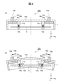
- FIG. 2A is a schematic diagram showing a state of the image pickup apparatus shown in FIG. 1 at room temperature
- FIG. 2B is a schematic diagram showing a state of the image pickup apparatus shown in FIG. 1 when the temperature rises.
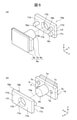
- An exploded perspective view of the image pickup apparatus shown in FIG. 5 (a) is an enlarged view of the camera module and the compensation holder shown in FIG. 4, and
- FIG. 5 (b) is a view of the camera module and the compensation holder viewed from a direction different from that of FIG. 5 (a).
- FIG. 5 (a) is an enlarged view of the camera module and the compensation holder shown in FIG. 4
- FIG. 5 (b) is a view of the camera module and the compensation holder viewed from a direction different from that of FIG. 5 (a).
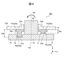
- FIG. 6 is a schematic view of a cross section of a main part obtained by cutting an image pickup apparatus by a plane parallel to the xz plane including the BB line shown in FIG.
- FIG. 7A is a schematic diagram showing a state of the image pickup apparatus shown in FIG. 4 at room temperature
- FIG. 7B is a schematic diagram showing a state of the image pickup apparatus shown in FIG. 4 when the temperature rises.
- FIG. 8 (a) is a diagram illustrating a compensating holder provided in the image pickup apparatus of the second embodiment
- FIG. 8 (b) illustrates an image pickup device of the second embodiment having a compensating holder different from that of FIG. 8 (a). Figure to do.
- FIG. 11 is a schematic view of a cross section of a main part obtained by cutting an image pickup apparatus by a plane parallel to the xz plane including the CC line shown in FIG. 13 (a) is a schematic view showing a state of the image pickup apparatus shown in FIG. 12 at room temperature, and FIG. 13 (b) is a state of the image pickup apparatus shown in FIG. 12 when the temperature rises and the cover is not provided.
- Schematic diagram showing the assumed state FIG. 13 (c) is a schematic diagram showing the state when the temperature of the image pickup apparatus shown in FIG. 12 rises and the circuit board is not provided.
- 13 (d) is a schematic diagram showing a state of the image pickup apparatus shown in FIG. 12 when the temperature rises.
- the direction in which the optical axis of the lens unit provided in the image pickup apparatus extends at room temperature is also referred to as "front-back direction".
- the front-back direction corresponds to the x-axis described in the drawings.
- “Front” is the direction in which the lens unit faces, and corresponds to the + x-axis direction.
- “Backward” is the opposite direction of the front and corresponds to the -x-axis direction.
- the direction along the direction of gravity is also referred to as “vertical direction”.
- the vertical direction corresponds to the y-axis described in the drawings.
- Downward is the direction toward the ground and corresponds to the -y-axis direction.
- “Upper” is the opposite direction of the lower direction and corresponds to the + y-axis direction.
- the directions orthogonal to each of the front-rear direction and the up-down direction are also referred to as "left-right direction”.
- the left-right direction corresponds to the z-axis described in the drawings.
- “Right” is the direction toward the right when the image pickup device is viewed from the rear to the front, and corresponds to the + z-axis direction.
- “Left” is the opposite direction to the right and corresponds to the -z axis direction.
- FIG. 1 is an exploded perspective view of the image pickup apparatus 200 of the comparative example.
- the image pickup device 200 is, for example, a stereo camera installed inside a windshield of a vehicle such as an automobile toward the front in the traveling direction to take an image of the periphery of the vehicle.
- the image pickup device 200 simultaneously images the surroundings of the vehicle by a pair of camera modules 6a and 6b, obtains a difference from the acquired pair of images, and exists in the vicinity of the vehicle such as a road, a preceding vehicle, a pedestrian, or an obstacle. It is possible to measure the distance to the object and the relative velocity.
- the measurement result is transmitted from the image pickup device 200 to the control device of the vehicle, and is used for processing and the like for controlling the running and braking of the vehicle.
- the image pickup device 200 includes a housing 1, a pair of camera modules 6a and 6b, and a circuit board 9 on which a circuit element for processing an output signal from the image pickup elements of the pair of camera modules 6a and 6b is mounted.
- the housing 1 accommodates a pair of camera modules 6a and 6b and a circuit board 9.
- the housing 1 is a long box-shaped metal housing extending in the left-right direction.
- the housing 1 is manufactured by, for example, aluminum die casting.
- the housing 1 has a linear expansion coefficient different from that of the circuit board 9.
- the housing 1 may have a linear expansion coefficient larger than that of the circuit board 9.
- the housing 1 has a plate-shaped front portion 10a extending along the left-right direction and facing forward, and a side surface portion 10b extending rearward from the peripheral edge portion of the front portion 10a.
- a plurality of plate-shaped heat radiating fins 10c extending in the vertical direction are provided on the outer side of the housing 1 in the front portion 10a at intervals along the left-right direction.
- attachment surfaces 11a and 11b for attaching the pair of camera modules 6a and 6b are provided at both ends in the left-right direction thereof.
- a through hole into which the lens units 4a and 4b provided in the camera modules 6a and 6b are inserted is provided in the central portion of the mounted surfaces 11a and 11b.
- attachment portions 11c to 11f for attaching the circuit board 9 are provided in the central portion located between both ends in the left-right direction thereof. That is, the attached portions 11c to 11f to which the circuit board 9 is attached are provided at positions closer to the central portion of the front portion 10a in the left-right direction than the attached surfaces 11a and 11b to which the camera modules 6a and 6b are attached.
- the housing 1 has an opening on the side opposite to the front portion 10a in the front-rear direction, and the opening portion is closed by the lid plate 8.
- the lid plate 8 is made of a metal plate such as an aluminum plate. As a result, the lid plate 8 can improve the dustproof property, heat dissipation property, and electromagnetic compatibility of the housing 1.
- the pair of camera modules 6a and 6b are attached to the attached surfaces 11a and 11b provided at both ends in the left-right direction of the housing 1, respectively.
- the pair of camera modules 6a and 6b are arranged so as to be spaced apart from each other along the left-right direction.
- the pair of camera modules 6a and 6b are arranged in such a posture that the optical axes 13a and 13b extend along the front-rear direction where the optical axes 13a and 13b intersect the front portion 10a.
- the left-right direction corresponds to an example of the "first direction” described in the claims
- the front-back direction corresponds to an example of the "second direction” described in the claims. That is, the front portion 10a of the housing 1 extends along the first direction.
- the optical axes 13a and 13b extend along the second direction.
- Each of the camera modules 6a and 6b includes an image sensor substrates 3a and 3b which are circuit boards on which an image sensor is mounted, lens units 4a and 4b for forming an image on the light receiving surface of the image sensor, and lens cylinders of the lens units 4a and 4b.
- the camera holders 5a and 5b to which the image sensor substrates 3a and 3b are connected are provided.
- the camera holder 5a is provided on the inner side of the housing 1 at the right end of the front portion 10a by using an adhesive or the like as a set of the image sensor substrate 3a on which the image sensor is mounted and the lens unit 4a. It is connected to the attached surface 11a. At this time, the lens unit 4a penetrates the front surface portion 10a by being inserted into the through hole provided in the central portion of the mounted surface 11a.
- the lens unit 4a is arranged in a posture in which the optical axis 13a extends in the front-rear direction (second direction) at the right end portion separated from the center portion of the front surface portion 10a along the left-right direction (first direction).
- the camera holder 5b is a set of an image sensor substrate 3b on which an image sensor is mounted and a lens unit 4b, and uses an adhesive or the like to form an internal side of a housing 1 at the left end of the front portion 10a. It is connected to the attached surface 11b provided in the above. At this time, the lens unit 4b penetrates the front surface portion 10a by being inserted into the through hole provided in the central portion of the mounted surface 11b.
- the lens unit 4b is arranged in a posture in which the optical axis 13b extends in the front-rear direction (second direction) at the left end portion separated from the center portion of the front surface portion 10a along the left-right direction (first direction).
- the circuit board 9 is provided so as to extend along the left-right direction (first direction).
- the circuit board 9 is, for example, a circuit board made of glass epoxy having a rectangular plate shape extending along the left-right direction (first direction).
- the circuit board 9 is arranged behind the camera modules 6a and 6b so as to face the front portion 10a in the front-rear direction (second direction) intersecting the front portion 10a.
- the circuit board 9 is connected to the attached portions 11c to 11f provided on the inner side of the housing 1 in the central portion of the front portion 10a by using the fastening members 15a to 15d.
- the circuit board 9 has a linear expansion coefficient different from that of the housing 1.
- the circuit board 9 may have a linear expansion coefficient smaller than that of the housing 1.
- FIG. 2A is a schematic diagram showing a state of the image pickup apparatus 200 shown in FIG. 1 at room temperature.
- FIG. 2B is a schematic diagram showing a state of the image pickup apparatus 200 shown in FIG. 1 when the temperature rises.
- 2 (a) and 2 (b) are schematic views of a cross section of the image pickup apparatus 200 cut by a plane parallel to the xz plane including the line AA shown in FIG.
- the front of the image pickup device 200 is imaged by a pair of camera modules 6a and 6b, and a pair of images are acquired.
- the image pickup apparatus 200 searches for feature points common to each other's images from the acquired pair of images.
- the circuit element of the circuit board 9 performs a process of obtaining the number of pixels (parallax) in which the positions of the searched feature points are deviated between the pair of images, and measures the distance to the object. Therefore, if an unintended deviation other than parallax occurs between the pair of images acquired by the pair of camera modules 6a and 6b, the accuracy of distance measurement may be greatly affected. The following events can be considered as one of the factors that cause this unintended deviation.
- the front portion 10a of the housing 1 bends due to the difference in the amount of thermal deformation of each component of the image pickup device 200. nothing.
- an event may occur in which the optical axes 13a and 13b of the lens units 4a and 4b are displaced from those at room temperature. In the present embodiment, this event is also referred to as "optical axis deviation of the lens units 4a and 4b due to thermal deformation".
- the permissible value of the optical axis deviation of the lens units 4a and 4b due to thermal deformation becomes smaller as the image pickup apparatus 200 has higher performance such as wide angle of view, high accuracy or high speed. Therefore, it is becoming more important to reduce the optical axis deviation.
- the number of pixels of the image sensor was small, the amount of heat generated by the image sensor was small and the temperature change was also small.
- the performance of the image pickup device 200 increases, the number of pixels of the image pickup element tends to increase significantly, the calorific value (power consumption) of the image pickup element and the circuit element increases significantly, and the temperature change also becomes large. There is a tendency.
- the heat dissipation area of the housing 1 tends to decrease with the miniaturization, and the temperature change tends to be further large. For this reason, in the image pickup apparatus 200, the difference in the amount of thermal deformation for each component becomes larger, and the optical axis deviation of the lens units 4a and 4b due to the thermal deformation becomes larger. It can have a huge impact.
- FIGS. 2A and 2B the principle of optical axis deviation of the lens units 4a and 4b due to thermal deformation will be described.
- the camera modules 6a and 6b are directly attached to the front portion 10a of the housing 1 by using an adhesive or the like.
- the circuit board 9 is directly attached to the front portion 10a of the housing 1 by using the fastening members 15a to 15d.
- the housing 1 and the circuit board 9 usually have different linear expansion coefficients.
- the front portion 10a of the housing 1 and the circuit board 9 have different amounts of thermal deformation in the longitudinal direction (left-right direction, first direction) of the front portion 10a of the housing 1.
- the front portion 10a of the housing 1 is one of the directions (front-back direction, second direction) intersecting the front portion 10a of the housing 1 due to the difference in the amount of thermal deformation between the front portion 10a of the housing 1 and the circuit board 9. Bend to the side.
- the optical axes 13a and 13b of the lens units 4a and 4b are the front portions of the housing 1 due to the bending of the front portion 10a of the housing 1 in the direction (front-back direction, second direction) intersecting the front portion 10a of the housing 1. It is inclined to one side or the other side in the longitudinal direction (left-right direction, first direction) of 10a.
- the thermal expansion amount of 9 is smaller than the thermal expansion amount in the longitudinal direction (left-right direction, first direction) of the front surface portion 10a of the housing 1.
- forces 12a and 12b act from the circuit board 9 toward the central portion on the attached portions 11c to 11f provided on the front portion 10a of the housing 1, and the casing.
- the optical axis 13a of the lens unit 4a is tilted to the right, which is one side of the front surface portion 10a of the housing 1 in the longitudinal direction (left-right direction, first direction), as shown by the arrow 14a.
- the optical axis 13b of the lens unit 4b is inclined to the left, which is the other side of the front surface portion 10a of the housing 1 in the longitudinal direction (left-right direction, first direction).
- the inclination of the optical axes 13a and 13b is the optical axis deviation of the lens units 4a and 4b due to thermal deformation.
- the image pickup apparatus 201 of the present embodiment includes an adjusting member for adjusting the optical axes 13a and 13b in order to reduce the optical axis deviation of the lens units 4a and 4b due to thermal deformation.
- the image pickup apparatus 201 of the first embodiment will be described with reference to FIGS. 3 to 7.
- the description of the configuration and operation similar to those of the comparative example will be omitted.
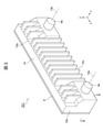
- FIG. 3 is an external perspective view of the image pickup apparatus 201 of the first embodiment.
- FIG. 4 is an exploded perspective view of the image pickup apparatus 201 shown in FIG.
- the image pickup apparatus 201 of the first embodiment includes the compensation holders 16a and 16b as adjusting members for adjusting the optical axes 13a and 13b.
- the image pickup apparatus 201 includes camera holders 7a and 7b that are different from the camera holders 5a and 5b of the comparative example.
- the camera modules 6a and 6b are attached to the front portion 10a of the housing 1a via the compensation holders 16a and 16b.
- the compensating holders 16a and 16b are connected to the attached surfaces 11a and 11b provided on the inner side of the housing 1a at the right end or the left end of the front portion 10a.
- the compensating holders 16a and 16b have different linear expansion coefficients from the housing 1a and the camera holders 7a and 7b.
- the compensating holders 16a and 16b have a linear expansion coefficient larger than that of the housing 1a and the camera holders 7a and 7b.
- FIG. 5A is an enlarged view of the camera module 6a and the compensation holder 16a shown in FIG.
- FIG. 5B is a view of the camera module 6a and the compensation holder 16a viewed from a direction different from that of FIG. 5A.
- FIG. 6 is a schematic view of a cross section of a main part obtained by cutting the image pickup apparatus 201 by a plane parallel to the xz plane including the line BB shown in FIG.
- the camera holder 7a has a plate-shaped flange portion 7c that holds the lens unit 4a.
- the flange portion 7c is formed so as to spread in the radial direction of the lens unit 4a along the left-right direction (first direction).
- a holding portion 7d for holding the lens unit 4a is formed in the central portion of the flange portion 7c so that the optical axis 13a is orthogonal to the flange portion 7c.
- the flange portion 7c has an inner portion 7e that is closer to the central portion of the front portion 10a of the housing 1a than the optical axis 13a in the left-right direction (first direction), and a casing than the optical axis 13a in the left-right direction (first direction). It has an outer portion 7f separated from the central portion of the front portion 10a of the body 1a.
- a recess 7g is formed in the inner portion 7e of the flange portion 7c.
- the recess 7g is recessed behind the surface of the flange 7c facing the compensating holder 16a.
- Convex portions 7h and 7i are formed on the outer portion 7f of the flange portion 7c.
- the convex portions 7h and 7i project forward from the surface of the flange portion 7c facing the compensating holder 16a.
- the convex portions 7h and 7i are formed so as to be arranged at intervals along the vertical direction.
- the camera holder 7b is also configured in the same manner as the camera holder 7a.
- the compensating holder 16a is arranged between the front portion 10a of the housing 1a and the flange portion 7c of the camera holder 7a in the front-rear direction (second direction), and connects the front portion 10a and the flange portion 7c.
- the compensating holder 16a has a plate portion 17a facing the front portion 10a of the housing 1a and facing the flange portion 7c of the camera holder 7a.
- the plate portion 17a is formed so as to spread in the radial direction of the lens unit 4a along the left-right direction (first direction).
- a through hole 17b for inserting the lens unit 4a is formed in the central portion of the plate portion 17a so that the optical axis 13a is orthogonal to the plate portion 17a.
- the plate portion 17a has an inner portion 17e that is closer to the central portion of the front portion 10a of the housing 1a than the optical axis 13a in the left-right direction (first direction), and a housing than the optical axis 13a in the left-right direction (first direction). It has an outer portion 17f separated from the central portion of the front portion 10a of the body 1a.
- An inner protrusion 18a is formed on the inner portion 17e of the plate portion 17a.
- the inner protrusion 18a protrudes rearward from the facing surface 17c of the plate portion 17a with the flange portion 7c along the front-rear direction (second direction), and is connected to the bottom surface of the recess 7g of the flange portion 7c by using an adhesive or the like.
- Outer protrusions 18b and 18c are formed on the outer portion 17f of the plate portion 17a.
- the outer protrusions 18b and 18c project rearward along the front-rear direction (second direction) from the facing surface 17c of the plate portion 17a with the flange portion 7c, and an adhesive or the like is used for the convex portions 7h and 7i of the flange portion 7c. Is connected.
- the inner protrusions 18a and the outer protrusions 18b and 18c have different dimensions along the front-rear direction (second direction).
- the dimensions of the inner protrusions 18a along the front-rear direction (second direction) are larger than the dimensions of the outer protrusions 18b and 18c along the front-rear direction (second direction).
- the surface of the plate portion 17a opposite to the facing surface 17c constitutes a connecting surface 17d connected to the attached surface 11a of the front surface portion 10a using an adhesive or the like.
- the compensating holder 16a is connected to the inner connecting portion 20a connected to the inner position of the front portion 10a closer to the central portion of the front portion 10a than the optical axis 13a in the left-right direction (first direction).
- the compensating holder 16a has an outer connecting portion 20b connected to an outer position of the front portion 10a separated from the central portion of the front portion 10a from the optical axis 13a in the left-right direction (first direction).
- the inner connecting portion 20a is composed of an inner portion 17e of the plate portion 17a and an inner protrusion portion 18a formed on the inner portion 17e.
- the inner connecting portion 20a connects the inner position of the front portion 10a with the flange portion 7c.
- the outer connecting portion 20b is composed of an outer portion 17f of the plate portion 17a and outer protrusions 18b and 18c formed on the outer portion 17f.
- the outer connecting portion 20b connects the outer position of the front portion 10a to the flange portion 7c.
- the inner connecting portion 20a and the outer connecting portion 20b have different dimensions along the direction (front-back direction, second direction) intersecting the front portion 10a of the housing 1.
- the dimension of the inner connecting portion 20a along the front-rear direction (second direction) is larger than the dimension of the outer connecting portion 20b along the front-rear direction (second direction).
- the first distance 25a from the connection position 21a of the inner connection portion 20a with the flange portion 7c to the connection position 22a of the inner connection portion 20a with the front surface portion 10a is connected to the flange portion 7c of the outer connection portion 20b.
- the length is different from the second distance 26a from the position 23a to the connection position 24a of the outer connecting portion 20b with the front portion 10a.
- the first distance 25a is longer than the second distance 26a.
- the inner connection portion 20a and the outer connection portion 20b have different amounts of thermal deformation in the direction (front-back direction, second direction) intersecting the front portion 10a of the housing 1.
- the difference in the amount of thermal deformation in the front-rear direction (second direction) between the inner connection portion 20a and the outer connection portion 20b is the difference in dimensions along the front-rear direction (second direction) between the inner connection portion 20a and the outer connection portion 20b. It is a difference according to.
- the compensating holder 16b is configured in the same manner as the compensating holder 16a. That is, the compensating holder 16a and the compensating holder 16b are configured to be symmetrical with each other in a plane (xy plane) that passes through the center of the front surface portion 10a of the housing 1a and is along the vertical direction.
- the dimension along the front-rear direction (second direction) of the inner connecting portion 20a is larger than the dimension along the front-rear direction (second direction) of the outer connecting portion 20b. big.
- the amount of thermal deformation of the inner connecting portion 20a in the front-rear direction (second direction) is larger than the amount of thermal deformation of the outer connecting portion 20b in the front-rear direction (second direction). ..
- FIG. 7A is a schematic diagram showing a state of the image pickup apparatus 201 shown in FIG. 4 at room temperature.
- FIG. 7B is a schematic diagram showing a state of the image pickup apparatus 201 shown in FIG. 4 when the temperature rises.
- 7 (a) and 7 (b) are views corresponding to FIG.
- the front portion 10a of the housing 1a becomes similar to the image pickup device 200 of the comparative example. , It bends so as to form a convex forward on one side of the direction (front-back direction, second direction) intersecting with the front surface portion 10a of the housing 1.
- the optical axis 13a of the lens unit 4a is tilted to the right, which is one side in the longitudinal direction (left-right direction, first direction) of the front portion 10a of the housing 1a, as shown by the arrow 14a.
- the optical axis 13b of the lens unit 4b is inclined to the left, which is the other side in the longitudinal direction (left-right direction, first direction) of the front portion 10a of the housing 1a, as shown by the arrow 14b.
- the compensating holders 16a and 16b have different linear expansion coefficients from those of the housing 1a and the camera holder 7a, and the inner connecting portion 20a and the outer connecting portion 20b intersect with the front portion 10a of the housing 1a.
- the dimensions along the front-back direction and the second direction) are different from each other. Therefore, in the compensating holders 16a and 16b, there is a difference in the amount of thermal deformation in the direction (front-back direction, second direction) intersecting the front portion 10a of the housing 1a between the inner connecting portion 20a and the outer connecting portion 20b.
- the compensating holders 16a and 16b have a linear expansion coefficient larger than that of the housing 1a and the camera holder 7a, and the dimension along the front-rear direction (second direction) of the inner connecting portion 20a is larger than that of the outer connecting portion 20b.
- the amount of thermal deformation of the inner connecting portion 20a in the front-rear direction (second direction) is larger than the amount of thermal deformation of the outer connecting portion 20b in the front-rear direction (second direction).
- the compensating holders 16a and 16b allow the lens units 4a and 4b to intersect the front portion 10a of the housing 1a in the intersecting direction (front-rear direction, second direction). It is tilted toward the other side (rear) in the direction (front-back direction, second direction) where the front portion 10a intersects with respect to the front portion 10a that is bent toward one side (front) of the direction). That is, the compensating holders 16a and 16b tilt the lens units 4a and 4b in the direction opposite to the bending direction (front) of the front portion 10a (rear) with respect to the front portion 10a of the housing 1a.
- the compensating holder 16a has the optical axis 13a of the lens unit 4a inclined to the right, which is one side of the longitudinal direction (left-right direction, first direction) of the front portion 10a of the housing 1a, and the front surface of the housing 1a.
- the portion 10a can be tilted to the left, which is the other side of the longitudinal direction (left-right direction, first direction).
- the compensating holder 16b has the optical axis 13b of the lens unit 4b inclined to the left, which is one side of the longitudinal direction (left-right direction, first direction) of the front portion 10a of the housing 1a, and the front surface of the housing 1a.
- the portion 10a can be tilted to the right, which is the other side in the longitudinal direction (left-right direction, first direction). That is, even if the front portions 10a of the compensating holders 16a and 16b are bent due to the difference in the amount of thermal deformation between the front portions 10a of the housing 1a and the circuit board 9, and the optical axes 13a and 13b are tilted in a predetermined direction.
- the optical axes 13a and 13b can be tilted in the opposite direction to the predetermined direction. Therefore, the compensating holders 16a and 16b can reduce the optical axis deviation of the lens units 4a and 4b due to thermal deformation.
- the compensating holders 16a and 16b are made of a resin or the like having a larger linear expansion coefficient than the housing 1a and the camera holder 7a, and the dimensions of the inner connecting portion 20a along the front-rear direction (second direction) are larger than those of the outer connecting portion 20b. If it is large, when the temperature rises, the amount of thermal expansion of the inner connecting portion 20a in the front-rear direction (second direction) becomes larger than that of the outer connecting portion 20b. As shown in FIG. 7B, the compensation holder 16a tilts the lens unit 4a relatively rearward with respect to the front portion 10a, and tilts the optical axis 13a to the left as shown by the arrow 14c. Can be done.
- the compensating holder 16b can tilt the lens unit 4b relatively rearward with respect to the front portion 10a, and tilt the optical axis 13b to the right as shown by the arrow 14d.
- the compensating holder 16a and the compensating holder 16b are configured to be symmetrical with each other in a plane (xy plane) that passes through the center of the front portion 10a of the housing 1a and is along the vertical direction, and the front surface due to thermal deformation of the housing 1a. It has a configuration corresponding to the bending of the portion 10a.
- the compensating holders 16a and 16b are the optical axes 13a and 13b of the lens units 4a and 4b that are inclined in a predetermined direction according to the difference in the amount of thermal deformation between the front portion 10a of the housing 1a and the circuit board 9. Due to the difference in the amount of thermal deformation between the inner connecting portion 20a and the outer connecting portion 20b, it can be tilted in the opposite direction to the predetermined direction.
- the compensating holders 16a and 16b form an adjusting member, and the optical axis deviation of the lens units 4a and 4b can be reduced by the thermal deformation of the compensating holders 16a and 16b.
- the image pickup apparatus 201 of the first embodiment can reduce the optical axis deviation of the lens units 4a and 4b due to thermal deformation even if the performance is improved, the number of pixels is increased, and the size is reduced.
- the image pickup device 201 of the first embodiment can secure the measurement accuracy of the distance with respect to the temperature change, and can provide a highly reliable image pickup device.
- the image pickup apparatus 201 of the first embodiment allows the heat deformation of the housing 1a and reduces the optical axis deviation of the lens units 4a and 4b due to the heat deformation.
- adding a reinforcing member such as a metal frame to the front portion 10a of the housing 1a is not preferable because it causes an increase in size and weight of the image pickup apparatus 201.
- the image pickup apparatus 201 of the first embodiment can reduce the optical axis deviation of the lens units 4a and 4b due to the thermal deformation while allowing the thermal deformation of the housing 1a, and thus suppresses the increase in size and weight. be able to.
- the image pickup apparatus 201 of the first embodiment is provided with the concave portions 7g and the convex portions 7h and 7i with respect to the flange portions 7c of the camera holders 7a and 7b, so that the compensating holders 16a and 16b are provided as compared with the case where the flange portions 7c are flat. Positioning with the inner protrusions 18a and the outer protrusions 18b and 18c of the above is facilitated. Further, in the image pickup apparatus 201 of the first embodiment, since the recesses 7g are provided in the flange portions 7c of the camera holders 7a and 7b, the inner protrusions of the compensating holders 16a and 16b are more than in the case where the flange portions 7c are flat.
- the dimension along the front-back direction (second direction) of 18a can be increased.
- the image pickup apparatus 201 of the first embodiment follows the front-rear direction (second direction) between the inner connection portion 20a and the outer connection portion 20b without increasing the distance between the plate portion 17a and the flange portion 7c. It is possible to easily secure the difference in dimensions, and it is possible to easily secure the difference in the amount of thermal deformation.
- the image pickup apparatus 201 of the first embodiment can reduce the optical axis deviation of the lens units 4a and 4b due to thermal deformation while reducing the thickness and weight of the image pickup apparatus 201.
- the flange portions 7c of the camera holders 7a and 7b may be flat without the concave portions 7g and the convex portions 7h and 7i.
- the time when the temperature of the image pickup apparatus 201 rises is taken as an example, but the image pickup apparatus 201 also has the same when the temperature drops. It is possible to reduce the optical axis deviation of the lens units 4a and 4b due to thermal deformation.
- the case where the linear expansion coefficient of the housing 1a is larger than that of the circuit board 9 and the linear expansion coefficient of the compensation holders 16a and 16b is larger than that of the camera holders 7a and 7b is taken as an example.
- the dimension of the portion 20a along the front-rear direction (second direction) was made larger than that of the outer connecting portion 20b (first distance 25a> second distance 26a).
- the inner connection portion 20a is in the front-rear direction (second).
- the dimension along the direction) may be made smaller than the outer connecting portion 20b (first distance 25a ⁇ second distance 26a).
- the inner connection portion 20a is in the front-rear direction (second).
- the dimension along the direction) may be made smaller than the outer connecting portion 20b (first distance 25a ⁇ second distance 26a).
- the inner connection portion 20a is in the front-rear direction (second).
- the dimension along the direction) may be made larger than the outer connecting portion 20b (first distance 25a> second distance 26a).
- the image pickup apparatus 201 can change the position in the left-right direction or the up-down direction and the dimension in the front-rear direction of the inner protrusion 18a or the outer protrusion 18b, 18c in the compensation holders 16a and 16b.
- the positions of the concave portions 7g or the convex portions 7h and 7i in the camera holders 7a and 7b in the left-right direction or the up-down direction and the dimensions in the front-rear direction can be changed.
- the image pickup apparatus 201 can appropriately control the postures of the lens units 4a and 4b in the vertical direction and the horizontal direction, respectively, and can reduce the optical axis deviation of the lens units 4a and 4b due to thermal deformation. can.
- the temperature distribution of the housing 1a is not uniform in the left-right direction (first direction), as in the case where the circuit elements mounted on the circuit board 9 are displaced and arranged in the left-right direction (first direction).
- the lens unit 4a and the lens unit 4b have different optical axis deviations due to thermal deformation.
- the image pickup apparatus 201 is thermally deformed by causing the dimensional difference between the inner connection portion 20a and the outer connection portion 20b in the front-rear direction (second direction) to be different between the compensation holder 16a and the compensation holder 16b. It is possible to reduce the optical axis deviation of the lens units 4a and 4b due to the above.
- the image sensor substrates 3a and 3b and the circuit board 9 are parallel to the front portion 10a of the housing 1a and are arranged along the direction of gravity has been described as an example. These arrangement relationships can be freely designed.
- the image pickup apparatus 201 can appropriately change the configurations of the compensating holders 16a and 16b according to these arrangement relationships.
- FIG. 8A is a diagram illustrating a compensating holder 30a provided in the image pickup apparatus 202 of the second embodiment.
- FIG. 8 (b) is a diagram illustrating an image pickup apparatus 202 of the second embodiment including a compensating holder 30c different from that of FIG. 8 (a).
- FIG. 8B is a diagram corresponding to FIG.
- the compensating holder 30a may be provided instead of the compensating holder 16a of the first embodiment.
- the compensating holder 30a is composed of a tubular member whose dimensions change along the front-rear direction (second direction) along the circumferential direction of the lens unit 4a.
- the compensating holder 30a is composed of a cylindrical member whose one end surface is inclined with respect to the central axis.
- the through hole 31b along the central axis of the compensating holder 30a constitutes a hole into which the lens unit 4a is inserted.
- the compensating holder 30a constitutes a connection surface 31c whose rear end surface is connected to the flange portion 39c of the camera holder 39a that holds the lens unit 4a of the image pickup apparatus 202.
- the compensating holder 30a constitutes a connection surface 31d whose front end surface is connected to the front portion 10a of the housing 1b of the image pickup apparatus 202.
- the inner portion 31e closer to the central portion of the front portion 10a of the housing 1b than the optical axis 13a in the left-right direction (first direction) constitutes the inner connecting portion 20a.
- the outer portion 31f separated from the central portion of the front portion 10a of the housing 1b from the optical axis 13a in the left-right direction (first direction) constitutes the outer connection portion 20b.
- the compensating holder 30a is formed so that the connecting surface 31c connected to the flange portion 39c of the camera holder 39a extends in the radial direction of the lens unit 4a along the left-right direction (first direction).
- the connection surface 31d connected to the front portion 10a of the housing 1b is gradually inclined rearward from the inner portion 31e to the outer portion 31f along the circumferential direction of the lens unit 4a. It is formed.
- the dimension of the inner connecting portion 20a along the front-rear direction (second direction) is larger than the dimension of the outer connecting portion 20b along the front-rear direction (second direction).
- the first distance 36a from the connection position 32a of the inner connection portion 20a with the flange portion 39c to the connection position 33a of the inner connection portion 20a with the front surface portion 10a is the connection position of the outer connection portion 20b with the flange portion 39c. It is longer than the second distance 37a from 34a to the connection position 35a of the outer connecting portion 20b with the front portion 10a.
- the dimensions of the inner connecting portion 20a along the front-rear direction (second direction) and the dimensions of the outer connecting portion 20b along the front-rear direction (second direction) are different from each other.
- the image pickup apparatus 200 of the second embodiment may be provided with a compensation holder 30c whose one end surface has a step between the inner portion 31e and the outer portion 31f. Similar to the compensation holder 30a shown in FIG. 8A, the compensation holder 30c is also composed of a tubular member whose dimensions change along the circumferential direction of the lens unit 4a in the front-rear direction (second direction).
- the image pickup apparatus 202 of the second embodiment includes the compensation holder 30a or the compensation holder 30c similar to the lens unit 4a side with respect to the lens unit 4b side.
- the compensating holder 30a or the compensating holder 30c constitutes an adjusting member.
- the image pickup apparatus 202 of the second embodiment has optical shafts 13a and 13b that are inclined in a predetermined direction according to a difference in the amount of thermal deformation between the front portion 10a of the housing 1b and the circuit board 9, and the inner connection portion 20a and the outer connection portion. Due to the difference in the amount of thermal deformation from 20b, it can be tilted in the opposite direction to the predetermined direction (see arrow 38a).
- the image pickup apparatus 202 of the second embodiment can reduce the optical axis deviation of the lens units 4a and 4b due to thermal deformation, and secures the measurement accuracy of the distance with respect to the temperature change. It is possible to provide a highly reliable image pickup apparatus.
- the image pickup apparatus 202 of the second embodiment can reduce the optical axis deviation of the lens units 4a and 4b due to the thermal deformation while allowing the thermal deformation of the housing 1b, so that the size and weight can be increased. It can be suppressed.
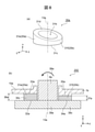
- FIG. 9 is a diagram illustrating the image pickup apparatus 203 of the third embodiment.
- FIG. 9 is a diagram corresponding to FIG.
- the compensating holder 40a may be provided instead of the compensating holder 16a of the first embodiment.
- the compensating holder 40a may have a configuration in which the plate portion 17a of the compensating holder 16a of the first embodiment is omitted. That is, the compensating holder 40a protrudes forward from the flange portion 39c of the camera holder 39a holding the lens unit 4a of the image pickup device 203 along the front-rear direction (second direction), and the front portion 10a of the housing 1c of the image pickup device 203. It is composed of an inner protrusion 45a and an outer protrusion 46a connected to.
- the inner protrusion 45a protrudes from the inner position (connection position 41a) of the flange portion 39c closer to the center of the front portion 10a of the housing 1c than the optical axis 13a in the left-right direction (first direction), and protrudes in the left-right direction (first direction). In one direction), it is connected to the inner position (connection position 42a) of the front portion 10a closer to the central portion of the front portion 10a of the housing 1c than the optical axis 13a.
- the outer protrusion 46a protrudes from the outer position (connection position 43a) of the flange portion 39c separated from the central portion of the front portion 10a of the housing 1c from the optical axis 13a in the left-right direction (first direction), and protrudes in the left-right direction (first direction). In one direction), it is connected to the outer position (connection position 44a) of the front portion 10a closer to the central portion of the front portion 10a of the housing 1c than the optical axis 13a.
- the outer protrusion 46a is composed of two outer protrusions arranged at intervals along the vertical direction.
- the inner protrusion 45a and the outer protrusion 46a may be integrally formed with the flange portion 39c of the camera holder 39a by insert molding or press-fit molding.
- the inner protrusion 45a constitutes the inner connection portion 20a.
- the outer protrusion 46a constitutes the outer connection portion 20b.
- the compensation holder 40a has substantially the same dimensions along the front-rear direction (second direction) of the inner connecting portion 20a and the dimensions along the front-rear direction (second direction) of the outer connecting portion 20b.
- the first distance 47a from the connection position 41a of the inner connection portion 20a with the flange portion 39c to the connection position 42a of the inner connection portion 20a with the front surface portion 10a is the connection position of the outer connection portion 20b with the flange portion 39c.
- the image pickup apparatus 203 of the third embodiment includes the same compensation holder 40a as the lens unit 4a side with respect to the lens unit 4b side.
- the compensating holder 40a constitutes an adjusting member.
- the image pickup apparatus 203 of the third embodiment has optical shafts 13a and 13b that are inclined in a predetermined direction according to a difference in the amount of thermal deformation between the front portion 10a of the housing 1c and the circuit board 9, and the inner connection portion 20a and the outer connection portion. Due to the difference in the amount of thermal deformation from 20b, it can be tilted in the opposite direction to the predetermined direction (see arrow 49a). Similar to the first embodiment, the image pickup apparatus 203 of the third embodiment can reduce the optical axis deviation of the lens units 4a and 4b due to thermal deformation, and secures the measurement accuracy of the distance with respect to the temperature change. It is possible to provide a highly reliable image pickup apparatus.
- the image pickup apparatus 203 of the third embodiment can reduce the optical axis deviation of the lens units 4a and 4b due to the thermal deformation while allowing the thermal deformation of the housing 1c, so that the size and weight can be increased. It can be suppressed.
- the image pickup device 203 of the third embodiment since the compensating holder 40a can be integrally formed with the flange portion 39c of the camera holder 39a, the same assembly as the existing image pickup device can be performed, and the image pickup device 203 can be assembled in the same manner as the existing image pickup device. It is also possible to improve the assemblability (productivity).
- the compensating holder 40a may not be integrally formed with the flange portion 39c of the camera holder 39a, but may be integrally formed with the front portion 10a of the housing 1c. That is, the compensating holder 40a protrudes rearward from the front portion 10a of the housing 1c along the front-rear direction (second direction), and is connected to the flange portion 39c of the camera holder 39a by the inner protrusion 45a and the outer protrusion 46a. It may be configured.
- the inner protrusion 45a and the outer protrusion 46a may be integrally formed with the front portion 10a of the housing 1c by insert molding or press-fit molding.
- the dimensions along the front-rear direction (second direction) of the inner protrusion 45a constituting the inner connection portion 20a and the front-rear direction (second direction) of the outer protrusion 46a constituting the outer connection portion 20b. ) May be different from each other.
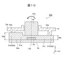
- FIG. 10 is a diagram illustrating the image pickup apparatus 204 of the fourth embodiment.
- FIG. 10 is a diagram corresponding to FIG.
- the image pickup apparatus 204 of the fourth embodiment is not provided with the compensation holders 16a and 16b as in the first embodiment.
- the adjusting member for adjusting the optical axis 13a may be configured by the camera holder 51a.
- the camera holder 51a has a linear expansion coefficient different from that of the housing 1d of the image pickup apparatus 204.
- the camera holder 51a is made of a resin or the like having a linear expansion coefficient larger than that of the housing 1d.
- the camera holder 51a has a flange portion 51c that extends in the radial direction of the lens unit 4a along the left-right direction (first direction), holds the lens unit 4a, and is attached to the inner side of the front portion 10a of the housing 1d. ..
- the camera holder 51a has an inner portion 51e that is closer to the center of the front portion 10a of the housing 1d than the optical axis 13a in the left-right direction (first direction) and a housing that is closer to the center than the optical axis 13a in the left-right direction (first direction). It has an outer portion 51f separated from the central portion of the front portion 10a of the body 1d.
- the inner portion 51e of the camera holder 51a constitutes an inner connecting portion 20a connected to the inner position (connection position 52a) of the front portion 10a of the housing 1d.
- the outer portion 51f of the camera holder 51a constitutes an outer connecting portion 20b connected to the outer position (connection position 53a) of the front portion 10a of the housing 1d.
- the camera holder 51a has different dimensions along the front-rear direction of the inner portion 51e constituting the inner connection portion 20a and the dimensions along the front-rear direction of the outer portion 51f constituting the outer connection portion 20b.
- the dimension of the inner portion 51e constituting the inner connecting portion 20a along the front-rear direction is larger than that of the outer portion 51f constituting the outer connecting portion 20b.
- the first distance 55a from the connection position 52a of the inner connection portion 20a with the front surface portion 10a to the element mounting surface 54a is the first distance from the connection position 53a of the outer connection portion 20b with the front surface portion 10a to the element mounting surface 54a. 2 Distance longer than 56a.
- the element mounting surface 54a is a surface on which the image pickup element 2a of the image pickup element substrate 3a is mounted.
- the image pickup apparatus 204 of the fourth embodiment includes a camera holder 51a similar to the lens unit 4a side with respect to the lens unit 4b side.
- the camera holder 51a constitutes an adjusting member.
- the image pickup apparatus 204 of the fourth embodiment has optical shafts 13a and 13b that are inclined in a predetermined direction according to a difference in the amount of thermal deformation between the front portion 10a of the housing 1d and the circuit board 9, and the inner connection portion 20a and the outer connection portion. Due to the difference in the amount of thermal deformation from 20b, it can be tilted in the opposite direction to the predetermined direction (see arrow 57a). Similar to the first embodiment, the image pickup apparatus 204 of the fourth embodiment can reduce the optical axis deviation of the lens units 4a and 4b due to thermal deformation, and secures the measurement accuracy of the distance with respect to the temperature change. It is possible to provide a highly reliable image pickup apparatus.
- the image pickup apparatus 204 of the fourth embodiment can reduce the optical axis deviation of the lens units 4a and 4b due to the thermal deformation while allowing the thermal deformation of the housing 1d, so that the size and weight can be increased. It can be suppressed. Further, since the image pickup apparatus 204 of the fourth embodiment does not require the compensating holders 16a and 16b as in the first embodiment, the weight can be reduced as compared with the first embodiment. Since the image pickup apparatus 204 of the fourth embodiment can be assembled in the same manner as the existing image pickup apparatus without adding new dedicated parts, the assemblability (productivity) is improved as compared with the first embodiment. Can be made to.
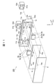
- FIG. 11 is a diagram illustrating the image pickup apparatus 205 of the fifth embodiment.
- FIG. 11 is a diagram corresponding to FIG. 4.
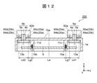
- FIG. 12 is a schematic view of a cross section of a main part obtained by cutting the image pickup apparatus 205 by a plane parallel to the xz plane including the CC line shown in FIG.
- the image pickup apparatus 205 of the fifth embodiment is not provided with the compensation holders 16a and 16b as in the first embodiment.
- the adjusting member for adjusting the optical axes 13a and 13b may be configured by the covers 62a and 62b.
- the covers 62a and 62b have a linear expansion coefficient different from that of the housing 1e of the image pickup apparatus 205.
- the covers 62a and 62b have a linear expansion coefficient smaller than that of the housing 1e.
- the covers 62a and 62b form a box shape extending in the radial direction of the lens units 4a and 4b along the left-right direction (first direction) and cover the front of the lens units 4a and 4b, and the front portion 10a of the housing 1e. It can be attached to the outside.
- the covers 62a and 62b may be provided with filters 61a and 61b on the front surface of the covers 62a and 62b facing the lens units 4a and 4b and orthogonal to the optical axes 13a and 13b. That is, the covers 62a and 62b may be filter covers that hold the filters 61a and 61b.
- the filters 61a and 61b may be a polarizing filter, a protective filter for preventing damage to the lens, or a dedicated filter for adjusting the optical axis.
- the cover 62a has four connecting pieces 64a, 64b and the like connected to the outer side of the housing 1e at the right end of the front portion 10a of the housing 1e, and four fastening members 65a, 65b and the like. Is connected rigidly using.
- the illustration of the two connecting pieces and the two fastening members arranged above the optical axis 13a is omitted. .. Of the four connection pieces 64a, 64b, etc.
- the 64b and the like and the two fastening members 65b and the like constitute an inner connecting portion 20a connected to the inner position of the front portion 10a of the housing 1e.
- the 64a and the like and the two fastening members 65a and the like constitute an outer connecting portion 20b connected to the outer position of the front portion 10a of the housing 1e.
- the cover 62b similarly to the cover 62a, the four connecting pieces 64c, 64d, etc. connected to the outer side of the housing 1e at the left end portion of the front portion 10a of the housing 1e, and the four fastening members 65c, 65d, etc. Is connected rigidly using.
- the illustration of the two connecting pieces and the two fastening members arranged above the optical axis 13b is omitted. ..
- the 64c and the like and the two fastening members 65c and the like constitute an inner connecting portion 20a connected to the inner position of the front portion 10a of the housing 1e.
- the 64d and the like and the two fastening members 65d and the like constitute an outer connecting portion 20b connected to the outer position of the front portion 10a of the housing 1e.
- the inner connecting portion 20a of the cover 62a is connected to a position on the right side of the front portion 10a of the mounted portions 11c and 11e of the circuit board 9 in the left-right direction (first direction).
- the inner connecting portion 20a of the cover 62b is connected to a position on the left side of the front portion 10a with respect to the mounted portions 11d and 11f of the circuit board 9 in the left-right direction (first direction). That is, the inner connecting portions 20a of the covers 62a and 62b are connected at positions separated from the central portion of the front portion 10a from the mounted portions 11c to 11f of the circuit board 9 in the left-right direction (first direction).
- the distance Lg1 is set in the left-right direction (first direction).
- Lg2 is present.
- the distances Lb1 and Lb2 between the inner connecting portions 20a and the outer connecting portions 20b of the covers 62a and 62b in the left-right direction (first direction) are the left and right of the attached portions 11c and 11e and the attached portions 11d and 11f of the circuit board 9. It is shorter than the interval La in the direction (first direction).
- FIG. 13A is a schematic diagram showing a state of the image pickup apparatus 205 shown in FIG. 12 at room temperature.
- FIG. 13B is a schematic diagram showing a state when the temperature of the image pickup apparatus 205 shown in FIG. 12 rises, and a state when it is assumed that the covers 62a and 62b are not provided.
- FIG. 13C is a schematic diagram showing a state when the temperature of the image pickup apparatus 205 shown in FIG. 12 rises, and a state when it is assumed that the circuit board 9 is not provided.
- FIG. 13D is a schematic diagram showing a state of the image pickup apparatus 205 shown in FIG. 12 when the temperature rises. 13 (a) to 13 (d) are views corresponding to FIG. 12.
- 13 (a) to 13 (d) show a case where the linear expansion coefficient of the housing 1e is larger than the linear expansion coefficient of the circuit board 9, and is larger than the linear expansion coefficient of the covers 62a and 62b. There is.
- the housing 1e is similar to the image pickup device 201 of the comparative example.
- the front portion 10a bends so as to form a convex forward.
- the optical axis 13a of the lens unit 4a is tilted to the right as shown by the arrow 67a
- the optical axis 13b of the lens unit 4b is tilted to the left as shown by the arrow 67b.
- forces 68c and 68d act toward the lens unit 4b with respect to the portion between the inner connecting portion 20a and the outer connecting portion 20b to which the cover 62b of the front portion 10a of the housing 1e is connected. Due to these forces 68a to 68d, the front portion 10a of the housing 1 near the lens units 4a and 4b is bent so as to form a convex rearward. As a result, the optical axis 13a of the lens unit 4a is tilted to the left as shown by the arrow 69a, and the optical axis 13b of the lens unit 4b is tilted to the right as shown by the arrow 69b. That is, the covers 62a and 62b bend the front portion 10a in the direction opposite to the bending direction of the front portion 10a when the covers 62a and 62b are not attached (FIG. 13 (b)).
- the image pickup apparatus 205 is in the state as shown in FIG. 13 (d) when the temperature of the image pickup apparatus 205 rises. That is, the image pickup apparatus 205 is in a state of being bent so as to be convex forward at the central portion of the front portion 10a of the housing 1e. In the portion of the front surface portion 10a of the housing 1e to which the lens units 4a and 4b are attached, the image pickup device 205 is in a state along the left-right direction (first direction) such as at room temperature because the deflection is canceled out.
- the covers 62a and 62b may regulate the bending of the portion of the front portion 10a to which the lens units 4a and 4b are attached by the difference in the amount of thermal deformation between the front portions 10a of the housing 1e and the covers 62a and 62b. can.
- the covers 62a and 62b can reduce the optical axis deviation of the lens units 4a and 4b due to thermal deformation.
- the covers 62a and 62b have the optical axes 13a and 13b that are inclined in a predetermined direction according to the difference in the amount of thermal deformation between the front portion 10a of the housing 1e and the circuit board 9, and the lens unit 4a of the front portion 10a.
- the covers 62a and 62b form an adjusting member, and the optical axis deviation of the lens units 4a and 4b can be reduced by the thermal deformation of the covers 62a and 62b.
- the image pickup apparatus 205 of the fifth embodiment can reduce the optical axis deviation of the lens units 4a and 4b due to thermal deformation even if the performance is improved, the number of pixels is increased, and the size is reduced. can. Similar to the first embodiment, the image pickup device 205 of the fifth embodiment can secure the measurement accuracy of the distance with respect to the temperature change, and can provide a highly reliable image pickup device.
- the image pickup apparatus 205 of the fifth embodiment does not require the compensating holders 16a and 16b as in the first embodiment, and uses the existing parts of the covers 62a and 62b. Since the image pickup device 205 of the fifth embodiment can be assembled with the same parts as the existing image pickup device without adding new dedicated parts, the assemblability (productivity) is improved as compared with the first embodiment. Can be done.
- the distances Lb1 and Lb2 between the inner connecting portions 20a and the outer connecting portions 20b of the covers 62a and 62b in the left-right direction (first direction) are the attached portions 11c and 11e and the attached portions 11d and 11f of the circuit board 9. It is shorter than the interval La in the left-right direction (first direction) of.
- the force for regulating the bending of the portion of the front portion 10a to which the lens units 4a and 4b are attached may be insufficient.
- the covers 62a and 62b are connected to the positions separated from the central portion of the front portion 10a by the mounted portions 11c to 11f of the circuit board 9 in the left-right direction (first direction). Will be done.
- the image pickup apparatus 205 of the fifth embodiment can efficiently generate a force for the covers 62a and 62b to regulate the bending of the portion of the front portion 10a to which the lens units 4a and 4b are attached.
- the image pickup apparatus 205 of the fifth embodiment can surely reduce the optical axis deviation of the lens units 4a and 4b due to thermal deformation.
- FIG. 14 is a diagram illustrating the image pickup apparatus 206 of the sixth embodiment.
- FIG. 14 is a diagram corresponding to FIG. 12.
- the image pickup apparatus 206 of the sixth embodiment may be provided with the covers 72a and 72b instead of the covers 62a and 62b of the fifth embodiment.
- the image pickup apparatus 206 of the sixth embodiment is provided with connection pieces 74a to 74d or the like instead of the connection pieces 64a to 64d of the fifth embodiment, and the fastening members 75a to 75d instead of the fastening members 65a to 65d of the fifth embodiment. Etc. may be provided.
- the image pickup apparatus 205 of the sixth embodiment may be provided with the attached portions 73c, 73d, etc. instead of the attached portions 11c, 11d, etc. of the circuit board 9.
- the inner connecting portions 20a of the covers 72a and 72b are connected at positions closer to the central portion of the front portion 10a than the attached portions 73c and 73d of the circuit board 9 in the left-right direction (first direction). That is, the positions where the circuit board 9 is connected to the front portion 10a are the positions where the inner connecting portions 20a of the covers 72a and 72b are connected to the front portion 10a and the positions of the covers 72a and 72b in the left-right direction (first direction). It is between the position where the outer connecting portion 20b is connected to the front portion 10a.
- the distances Lb1 and Lb2 between the inner connecting portions 20a and the outer connecting portions 20b of the covers 72a and 72b in the left-right direction (first direction) are the left and right of the attached portions 11c and 11e and the attached portions 11d and 11f of the circuit board 9. It overlaps with the interval La in the direction (first direction) in the front-back direction.
- the lengths of the regions where the intervals Lb1 and Lb2 and the intervals La overlap in the left-right direction (first direction) are defined as LL1 and LL2.
- the covers 72a and 72b form an adjusting member.
- the image pickup apparatus 206 of the sixth embodiment has an optical axis 13a, 13b that is inclined in a predetermined direction according to a difference in the amount of thermal deformation between the front portion 10a of the housing 1f and the circuit board 9. By restricting the bending of the portion to which the lens units 4a and 4b of the portion 10a are attached, it is possible to incline in the opposite direction of the predetermined direction.
- the image pickup apparatus 206 of the sixth embodiment can reduce the optical axis deviation of the lens units 4a and 4b due to thermal deformation, and secures the measurement accuracy of the distance with respect to the temperature change. It is possible to provide a highly reliable image pickup apparatus.
- the image pickup apparatus 206 of the sixth embodiment does not require the compensating holders 16a and 16b as in the first embodiment, and uses the existing parts of the covers 72a and 72b. Since the image pickup apparatus 206 of the sixth embodiment can be assembled with the same parts as the existing image pickup apparatus without adding new dedicated parts, the assemblability (as in the fifth embodiment) is higher than that of the first embodiment. Productivity) can be improved.
- the distance Lg1 is between the position where the inner connecting portions 20a of the covers 62a and 62b are connected to the front portion 10a and the position where the circuit board 9 is connected to the front portion 10a.
- Lg2 is present.
- the housing 1e when the housing 1e is thermally deformed, the housing 1e may bend in the region where the distances Lg1 and Lg2 of the front portion 10a exist. From the viewpoint of assembleability and durability, it is preferable that the amount of thermal deformation of the housing 1e is small.
- the intervals Lb1 and Lb2 and the interval La overlap in the front-rear direction.
- the housing 1f when the housing 1f is thermally deformed, the housing 1f does not bend and bends gently in the region where the spacing Lb1 and Lb2 of the front portion 10a and the spacing La overlap. It becomes. Since the image pickup apparatus 206 of the sixth embodiment can reduce the amount of thermal deformation of the housing 1f as compared with the fifth embodiment, it is possible to improve the assembleability and durability.
- the covers 62a and 62b are attached to the lenses units 4a and 4b of the front portion 10a. It becomes difficult to efficiently generate a force that regulates the bending of the damaged portion. It is preferable that the lengths LL1 and LL2 are zero or more and smaller than half of the intervals Lb1 and Lb2 (0 ⁇ LL1 ⁇ (Lb1) / 2,0 ⁇ LL2 ⁇ (Lb2) / 2).
- the temperature distribution of the housing 1f is not uniform in the left-right direction (first direction), as in the case where the circuit elements mounted on the circuit board 9 are displaced and arranged in the left-right direction (first direction).
- the lens unit 4a and the lens unit 4b have different optical axis deviations due to thermal deformation.
- the image pickup apparatus 206 can reduce the optical axis deviation of the lens units 4a and 4b due to thermal deformation by setting the spacing Lb1 and the spacing Lb2 to different lengths.
- FIG. 15 is a diagram illustrating the image pickup apparatus 207 of the seventh embodiment.
- FIG. 15 is a diagram corresponding to FIG. 12.
- the image pickup apparatus 207 of the seventh embodiment is not provided with the covers 62a and 62b as in the fifth embodiment.
- the image pickup apparatus 207 of the seventh embodiment may be provided with the camera holders 81a and 81b instead of the camera holders 5a and 5b of the fifth embodiment.
- the adjusting member for adjusting the optical axes 13a and 13b may be configured by the camera holders 81a and 81b.
- the camera holders 81a and 81b have a linear expansion coefficient different from that of the housing 1g of the image pickup apparatus 207.
- the camera holders 81a and 81b are made of a resin or the like having a linear expansion coefficient larger than that of the housing 1g.
- the camera holders 81a and 81b have flange portions 82a and 82b extending in the radial direction of the lens units 4a and 4b along the left-right direction (first direction) to hold the lens units 4a and 4b, and the front surface of the housing 1g. It is attached to the inner side of the portion 10a.
- the flange portion 82a of the camera holder 81a is rigidly connected to the right end portion of the front portion 10a of the housing 1g by using four fastening members 85a, 85b and the like.
- FIG. 15 of the four fastening members 85a, 85b, etc. the illustration of the two fastening members arranged above the optical axis 13a is omitted.
- the two fastening members 85b, etc. that are closer to the center of the front portion 10a of the housing 1g than the optical axis 13a in the left-right direction (first direction) are the front surfaces of the housing 1g. It constitutes an inner connecting portion 20a connected to the inner position of the portion 10a.
- the two fastening members 85a, 85b, etc. separated from the central portion of the front portion 10a of the housing 1g from the optical axis 13a in the left-right direction (first direction) are the front surfaces of the housing 1g.
- the outer connecting portion 20b connected to the outer position of the portion 10a is configured.
- the flange portions 82b and fastening members 85c and 85d of the camera holder 81b are the same as the flange portions 82a and fastening members 85a and 85b of the camera holder 81a.
- the camera holders 81a and 81b can regulate the bending of the portion of the front portion 10a to which the lens units 4a and 4b are attached by the difference in the amount of thermal deformation between the front portion 10a and the camera holders 81a and 81b.
- the optical axes 13a and 13b of the camera holders 81a and 81b are tilted in a predetermined direction due to the difference in the amount of thermal deformation between the front portion 10a of the housing 1g and the circuit board 9, the optical axes 13a, 13b can be tilted in the opposite direction of the predetermined direction. Therefore, the camera holders 81a and 81b can reduce the optical axis deviation of the lens units 4a and 4b due to thermal deformation.
- the camera holders 81a and 81b form an adjusting member.
- the image pickup apparatus 207 of the seventh embodiment has an optical axis 13a, 13b that is inclined in a predetermined direction according to a difference in the amount of thermal deformation between the front portion 10a of the housing 1g and the circuit board 9. By restricting the bending of the portion to which the lens units 4a and 4b of the portion 10a are attached, it is possible to incline in the opposite direction of the predetermined direction.
- the image pickup apparatus 207 of the seventh embodiment can reduce the optical axis deviation of the lens units 4a and 4b due to thermal deformation, and secures the measurement accuracy of the distance with respect to the temperature change. It is possible to provide a highly reliable image pickup apparatus.
- the image pickup apparatus 207 of the seventh embodiment is lighter than the first and fifth embodiments because the compensating holders 16a and 16b as in the first embodiment and the covers 62a and 62b as in the fifth embodiment are unnecessary. Can be planned. Since the image pickup apparatus 207 of the seventh embodiment can be assembled in the same manner as the existing image pickup apparatus without adding new dedicated parts, it is easier to assemble (production) than the first embodiment and the fifth embodiment. Sex) can be improved.
- the image pickup devices 201 to 207 have been described as stereo cameras, but the image pickup devices 201 to 207 may be monocular cameras.
- the present invention is not limited to the above embodiment, and includes various modifications.
- the above-described embodiment has been described in detail in order to explain the present invention in an easy-to-understand manner, and is not necessarily limited to the one including all the described configurations.
- it is possible to replace a part of the configuration of one embodiment with the configuration of another embodiment and it is also possible to add the configuration of another embodiment to the configuration of one embodiment.
- each of the above configurations, functions, processing units, processing means, etc. may be realized by hardware by designing a part or all of them by, for example, an integrated circuit. Further, each of the above configurations, functions, and the like may be realized by software by the processor interpreting and executing a program that realizes each function. Information such as programs, tapes, and files that realize each function can be placed in a memory, a recording device such as a hard disk or SSD (solid state drive), or a recording medium such as an IC card, SD card, or DVD.
- a recording device such as a hard disk or SSD (solid state drive)
- a recording medium such as an IC card, SD card, or DVD.
- control lines and information lines indicate those that are considered necessary for explanation, and do not necessarily indicate all control lines and information lines in the product. In practice, it can be considered that almost all configurations are interconnected.
Landscapes
- Engineering & Computer Science (AREA)
- Physics & Mathematics (AREA)
- General Physics & Mathematics (AREA)
- Multimedia (AREA)
- Signal Processing (AREA)
- Aviation & Aerospace Engineering (AREA)
- Studio Devices (AREA)
- Lens Barrels (AREA)
Abstract
本発明は、レンズユニットの光軸ずれを低減することが可能な撮像装置を提供する。撮像装置201は、第1方向に沿って延びる正面部10aを有する筐体1aと、筐体1aと異なる線膨張係数を有し、第2方向において正面部10aに対向配置され、正面部10aに取り付けられる回路基板9と、正面部10aの端部において光軸13a,13bが第2方向に延びる姿勢に配置され、正面部10aに取り付けられるレンズユニット4a,4bと、筐体1aと異なる線膨張係数を有し、正面部10aに取り付けられ、光軸13a,13bを調整する調整部材と、を備える。正面部10aは、正面部10aと回路基板9との熱変形量の差によって第2方向の一方側に撓む。光軸13a,13bは、正面部10aの撓みによって第1方向の一方側に傾斜する。調整部材は、傾斜する光軸13a,13bを、調整部材の熱変形によって第1方向の他方側に傾斜させる。
Description
本発明は、撮像装置に関する。
近年、安全且つ快適なクルマ社会の実現を目指して、運転支援システムの実車搭載が進んでいる。特に、衝突前の停止動作を自動で行う衝突被害軽減制動装置、先行車両を自動追尾する車間自動制御装置、車線逸脱抑制装置、又は、標識認識等の、運転者及び搭乗者の安全性、利便性及び快適性を追求したシステムの開発が進んでいる。このようなシステムを実現するためには、例えば、他車両や歩行者等の車両周辺の物体を認識して物体までの距離を測定する外界認識システムが重要である。この外界認識システムの1つとして、ステレオカメラが知られている(例えば、特許文献1)。
特許文献1には、第1カメラが電気的に接続される第1端部と第2カメラが電気的に接続される第2端部とを有する回路基板と、第1フレーム部材と第2フレーム部材と車両に取り付けるためのマウントとを有するフレームとを備えるカメラシステムが記載されている。特許文献1のカメラシステムでは、回路基板が、第1フレーム部材と第2フレーム部材との間に配置される。特許文献1のカメラシステムでは、回路基板の第1及び第2端部のマウントに対する撓みを抑制し、第1カメラと第2カメラの配置を保持するため、第1フレーム部材が、第1端部近傍の第1連結位置と前記第2端部近傍の第2連結位置で第2フレーム部材に連結される。
特許文献1のカメラシステムは、回路基板の撓みを抑制するために補強部材として第2フレーム部材を設けることにより、結果的に、回路基板の撓みによって発生するレンズユニットの光軸ずれを低減しているに過ぎない。特許文献1のカメラシステムは、回路基板及びレンズユニットを収容するハウジングの撓みによって発生するレンズユニットの光軸ずれを低減することができない可能性があり、改善の余地がある。
本発明は、上記に鑑みてなされたものであり、レンズユニットの光軸ずれを低減することが可能な撮像装置を提供することを目的とする。
上記課題を解決するために、本発明に係る撮像装置は、第1方向に沿って延びる板状の正面部を有する筐体と、前記筐体と異なる線膨張係数を有し、前記正面部と交差する第2方向において前記正面部に対向して配置され、前記正面部に取り付けられる回路基板と、前記正面部の中央部から前記第1方向に沿って離隔した端部において光軸が前記第2方向に沿って延びる姿勢に配置され、前記正面部に取り付けられるレンズユニットと、前記筐体と異なる線膨張係数を有し、前記正面部に取り付けられ、前記レンズユニットの前記光軸を調整する調整部材と、を備え、前記正面部は、前記正面部と前記回路基板との熱変形量の差によって前記第2方向の一方側に撓み、前記光軸は、前記正面部の前記第2方向における撓みによって前記第1方向の一方側に傾斜し、前記調整部材は、前記第1方向の一方側に傾斜する前記光軸を、前記調整部材の熱変形によって前記第1方向の他方側に傾斜させることを特徴とする。
本発明によれば、レンズユニットの光軸ずれを低減することが可能な撮像装置を提供することができる。
上記以外の課題、構成および効果は、以下の実施形態の説明により明らかにされる。
上記以外の課題、構成および効果は、以下の実施形態の説明により明らかにされる。
以下、本発明の実施形態について図面を用いて説明する。各実施形態において同一の符号を付された構成は、特に言及しない限り、各実施形態において同様の機能を有し、その説明を省略する。また、必要な図面には、各部の位置の説明を明確にするべく、x軸、y軸及びz軸から成る直交座標軸を記載している。
本実施形態では、常温時において撮像装置に備えられたレンズユニットの光軸が延びる方向を「前後方向」とも称する。前後方向は、図面に記載のx軸に対応する。「前方」は、レンズユニットの向く方向であり、+x軸方向に対応する。「後方」は、前方の逆方向であり、-x軸方向に対応する。本実施形態では、重力方向に沿った方向を「上下方向」とも称する。上下方向は、図面に記載のy軸に対応する。「下方」は、地面へ向かう方向であり、-y軸方向に対応する。「上方」は、下方の逆方向であり、+y軸方向に対応する。本実施形態では、前後方向及び上下方向のそれぞれに直交する方向を「左右方向」とも称する。左右方向は、図面に記載のz軸に対応する。「右方」は、後方から前方へ撮像装置を視たときに右へ向かう方向であり、+z軸方向に対応する。「左方」は、右方の逆方向であり、-z軸方向に対応する。
[実施形態1]
まず、図1及び図2を用いて、比較例の撮像装置200について説明する。図1は、比較例の撮像装置200の分解斜視図である。
まず、図1及び図2を用いて、比較例の撮像装置200について説明する。図1は、比較例の撮像装置200の分解斜視図である。
撮像装置200は、例えば、自動車等の車両のウィンドシールドの内側に進行方向前方に向けて設置され、車両の周辺を撮像するステレオカメラである。撮像装置200は、一対のカメラモジュール6a,6bにより車両の周辺を同時に撮像し、取得された一対の画像から視差を求めて、道路、先行車両、歩行者又は障害物等の車両の周辺に存在する物体までの距離や相対速度等を測定することができる。測定結果は、撮像装置200から車両の制御装置へ送信され、車両の走行や制動等を制御する処理等に使用される。
撮像装置200は、筐体1と、一対のカメラモジュール6a,6bと、一対のカメラモジュール6a,6bの撮像素子からの出力信号を処理する回路素子を搭載する回路基板9とを備える。
筐体1は、一対のカメラモジュール6a,6b及び回路基板9を収容する。筐体1は、左右方向に沿って延びる長尺の箱状を成す金属製の筐体である。筐体1は、例えば、アルミダイカスト等によって製造される。筐体1は、回路基板9とは異なる線膨張係数を有する。例えば、筐体1は、回路基板9より大きい線膨張係数を有してもよい。
筐体1は、左右方向に沿って延びて前方に面する板状の正面部10aと、正面部10aの周縁部から後方に延びる側面部10bとを有する。正面部10aにおける筐体1の外部側には、上下方向に延びる板状の放熱フィン10cが左右方向に沿って間隔を空けて複数設けられる。正面部10aにおける筐体1の内部側には、その左右方向の両端部に、一対のカメラモジュール6a,6bを取り付けるための被取り付け面11a,11bが設けられる。被取り付け面11a,11bの中央部には、カメラモジュール6a,6bに備えられたレンズユニット4a,4bが挿入される貫通孔が設けられる。更に、正面部10aにおける筐体1の内部側には、その左右方向の両端部の間に位置する中央部に、回路基板9を取り付けるための被取り付け部11c~11fが設けられる。すなわち、回路基板9が取り付けられる被取り付け部11c~11fは、カメラモジュール6a,6bが取り付けられる被取り付け面11a,11bよりも、左右方向において正面部10aの中央部に接近した位置に設けられる。
また、筐体1は、前後方向における正面部10aとは反対側の部分が開口しており、当該開口部分は、蓋板8によって閉塞される。蓋板8は、アルミ板等の金属板により構成される。これにより、蓋板8は、筐体1の防塵性、放熱性及び電磁両立性を向上させることができる。
一対のカメラモジュール6a,6bは、筐体1の左右方向の両端部に設けられた被取り付け面11a,11bにそれぞれ取り付けられる。一対のカメラモジュール6a,6bは、左右方向に沿って互いに間隔を空けて配置される。一対のカメラモジュール6a,6bは、光軸13a,13bが正面部10aと交差する前後方向に沿って延びるような姿勢にて配置される。本実施形態において、左右方向は、特許請求の範囲に記載の「第1方向」の一例に該当し、前後方向は、特許請求の範囲に記載の「第2方向」の一例に該当する。すなわち、筐体1の正面部10aは、第1方向に沿って延びる。光軸13a,13bは、第2方向に沿って延びる。
カメラモジュール6a,6bのそれぞれは、撮像素子を搭載した回路基板である撮像素子基板3a,3bと、撮像素子の受光面に結像させるレンズユニット4a,4bと、レンズユニット4a,4bの鏡筒を保持すると共に撮像素子基板3a,3bが接続されるカメラホルダ5a,5bとを備える。
カメラホルダ5aは、撮像素子が搭載された撮像素子基板3aと、レンズユニット4aとを一組にして、接着材等を用いて、正面部10aの右端部における筐体1の内部側に設けられた被取り付け面11aに接続される。この際、レンズユニット4aは、被取り付け面11aの中央部に設けられた貫通孔に挿入されることによって正面部10aを貫通する。そして、レンズユニット4aは、正面部10aの中央部から左右方向(第1方向)に沿って離隔した右端部において光軸13aが前後方向(第2方向)に沿って延びる姿勢に配置される。
同様に、カメラホルダ5bは、撮像素子が搭載された撮像素子基板3bと、レンズユニット4bとを一組にして、接着材等を用いて、正面部10aの左端部における筐体1の内部側に設けられた被取り付け面11bに接続される。この際、レンズユニット4bは、被取り付け面11bの中央部に設けられた貫通孔に挿入されることによって正面部10aを貫通する。そして、レンズユニット4bは、正面部10aの中央部から左右方向(第1方向)に沿って離隔した左端部において光軸13bが前後方向(第2方向)に沿って延びる姿勢に配置される。
回路基板9は、左右方向(第1方向)に沿って延びるように設けられる。回路基板9は、例えば、左右方向(第1方向)に沿って延びる矩形の板状を成すガラスエポキシ製の回路基板である。回路基板9は、カメラモジュール6a,6bの後方において、正面部10aと交差する前後方向(第2方向)において正面部10aに対向して配置される。回路基板9は、締結部材15a~15dを用いて、正面部10aの中央部における筐体1の内部側に設けられた被取り付け部11c~11fに接続される。回路基板9は、筐体1と異なる線膨張係数を有する。例えば、回路基板9は、筐体1より小さい線膨張係数を有してもよい。
図2(a)は、図1に示す撮像装置200の常温時の状態を示す模式図である。図2(b)は、図1に示す撮像装置200の温度上昇時の状態を示す模式図である。図2(a)及び図2(b)は、図1に示すA-A線を含みxz平面に平行な平面によって撮像装置200を切断した断面の模式図である。
撮像装置200では、一対のカメラモジュール6a,6bにより撮像装置200の前方を撮像し、一対の画像を取得する。撮像装置200では、取得された一対の画像の中から相互の画像に共通する特徴点を探索する。撮像装置200では、探索された特徴点の位置が一対の画像間でずれている画素数(視差)を求める処理を、回路基板9の回路素子で行って、物体までの距離を測定する。よって、一対のカメラモジュール6a,6bにより取得された一対の画像間に、視差以外の意図しないずれが発生すると、距離の測定精度に多大な影響を及ぼす可能性がある。この意図しないずれが発生する要因の1つに、次のような事象が考えられる。
すなわち、撮像装置200は、内部の発熱や太陽光の輻射熱等により撮像装置200の温度が変化すると、撮像装置200の各構成要素の熱変形量の差によって、筐体1の正面部10aが撓む。これにより、撮像装置200は、筐体1の正面部10aが撓むと、レンズユニット4a,4bの光軸13a,13bが常温時と比べてずれる事象が発生し得る。本実施形態では、この事象を「熱変形に起因するレンズユニット4a,4bの光軸ずれ」とも称する。
また、撮像装置200では、広画角化、高精度化又は高速化等の撮像装置200の高性能化に伴って、熱変形に起因するレンズユニット4a,4bの光軸ずれの許容値が小さくなっており、当該光軸ずれを低減する重要性が高まっている。撮像素子の画素数等が少ない場合、撮像素子の発熱量が小さく、温度変化も小さかった。しかしながら、撮像装置200の高性能化に伴って、撮像素子の画素数が大幅に増加する傾向にあり、撮像素子や回路素子の発熱量(消費電力)が大幅に増加し、温度変化も大きくなる傾向にある。更に、撮像装置200では、小型化に伴って筐体1の放熱面積が減少し、温度変化が更に大きくなる傾向にある。このようなことから、撮像装置200では、構成要素毎の熱変形量の差が更に大きくなり、熱変形に起因するレンズユニット4a,4bの光軸ずれが更に大きくなるので、距離の測定精度に多大な影響を及ぼす可能性がある。
図2(a)及び図2(b)を用いて、熱変形に起因するレンズユニット4a,4bの光軸ずれが発生する原理を説明する。撮像装置200では、カメラモジュール6a,6bが接着材等を用いて筐体1の正面部10aに直接取り付けられている。撮像装置200では、回路基板9が締結部材15a~15dを用いて筐体1の正面部10aに直接取り付けられている。筐体1と回路基板9とは、通常、線膨張係数が互いに異なる。撮像装置200の温度変化時、筐体1の正面部10aと回路基板9とは、筐体1の正面部10aの長手方向(左右方向、第1方向)における熱変形量が互いに異なる。筐体1の正面部10aは、筐体1の正面部10aと回路基板9との熱変形量の差によって、筐体1の正面部10aと交差する方向(前後方向、第2方向)の一方側に撓む。レンズユニット4a,4bの光軸13a,13bは、筐体1の正面部10aと交差する方向(前後方向、第2方向)における筐体1の正面部10aの撓みによって、筐体1の正面部10aの長手方向(左右方向、第1方向)の一方側又は他方側に傾斜する。
例えば、筐体1の線膨張係数が回路基板9の線膨張係数より大きい場合、撮像装置200の温度上昇時、筐体1の正面部10aの長手方向(左右方向、第1方向)における回路基板9の熱膨張量は、筐体1の正面部10aの長手方向(左右方向、第1方向)の熱膨張量に対して小さくなる。この場合、図2(b)に示すように、筐体1の正面部10aに設けられた被取り付け部11c~11fに対して回路基板9から中央部に向かって力12a,12bが働き、筐体1の正面部10aと交差する方向(前後方向、第2方向)の一方側である前方に凸を成すように撓む。これにより、レンズユニット4aの光軸13aは、矢印14aにて示すように、筐体1の正面部10aの長手方向(左右方向、第1方向)の一方側である右方に傾斜する。同様に、レンズユニット4bの光軸13bは、矢印14bにて示すように、筐体1の正面部10aの長手方向(左右方向、第1方向)の他方側である左方に傾斜する。この光軸13a,13bの傾斜が、熱変形に起因するレンズユニット4a,4bの光軸ずれである。
そこで、本実施形態の撮像装置201では、熱変形に起因するレンズユニット4a,4bの光軸ずれを低減するために、光軸13a,13bを調整する調整部材を備える。
続いて、図3~図7を用いて、実施形態1の撮像装置201について説明する。実施形態1の説明において、比較例と同様の構成及び動作については説明を省略する。
図3は、実施形態1の撮像装置201の外観斜視図である。図4は、図3に示す撮像装置201の分解斜視図である。
実施形態1の撮像装置201は、図4に示すように、光軸13a,13bを調整する調整部材として、補整ホルダ16a,16bを備える。撮像装置201は、比較例のカメラホルダ5a,5bとは異なるカメラホルダ7a,7bを備える。撮像装置201では、カメラモジュール6a,6bが補整ホルダ16a,16bを介して筐体1aの正面部10aに取り付けられる。補整ホルダ16a,16bは、正面部10aの右端部又は左端部における筐体1aの内部側に設けられた被取り付け面11a,11bに接続される。補整ホルダ16a,16bは、筐体1a及びカメラホルダ7a,7bと異なる線膨張係数を有する。本実施形態では、補整ホルダ16a,16bは、筐体1a及びカメラホルダ7a,7bよりも大きい線膨張係数を有する。
図5(a)は、図4に示すカメラモジュール6a及び補整ホルダ16aの拡大図である。図5(b)は、図5(a)と異なる方向からカメラモジュール6a及び補整ホルダ16aを視た図である。図6は、図4に示すB-B線を含みxz平面に平行な平面によって撮像装置201を切断した要部断面の模式図である。
カメラホルダ7aは、図5(b)に示すように、レンズユニット4aを保持する板状のフランジ部7cを有する。フランジ部7cは、左右方向(第1方向)に沿ってレンズユニット4aの径方向に広がるように形成される。フランジ部7cは、その中央部に、光軸13aがフランジ部7cと直交するようにレンズユニット4aを保持する保持部7dが形成される。
フランジ部7cは、左右方向(第1方向)において光軸13aよりも筐体1aの正面部10aの中央部に接近した内側部分7eと、左右方向(第1方向)において光軸13aよりも筐体1aの正面部10aの中央部から離隔した外側部分7fとを有する。フランジ部7cの内側部分7eには、凹部7gが形成される。凹部7gは、フランジ部7cの補整ホルダ16aとの対向面よりも後方に窪む。フランジ部7cの外側部分7fには、凸部7h,7iが形成される。凸部7h,7iは、フランジ部7cの補整ホルダ16aとの対向面よりも前方に突出する。凸部7h,7iは、上下方向に沿って間隔を空けて並ぶように形成される。なお、カメラホルダ7bについても、カメラホルダ7aと同様に構成される。
補整ホルダ16aは、前後方向(第2方向)において筐体1aの正面部10aとカメラホルダ7aのフランジ部7cとの間に配置され、正面部10aとフランジ部7cとを接続する。補整ホルダ16aは、図5(a)及び図5(b)に示すように、筐体1aの正面部10aに対向すると共にカメラホルダ7aのフランジ部7cに対向する板部17aを有する。板部17aは、左右方向(第1方向)に沿ってレンズユニット4aの径方向に広がるように形成される。板部17aは、その中央部に、光軸13aが板部17aと直交するようにレンズユニット4aを挿入するための貫通孔17bが形成される。
板部17aは、左右方向(第1方向)において光軸13aよりも筐体1aの正面部10aの中央部に接近した内側部分17eと、左右方向(第1方向)において光軸13aよりも筐体1aの正面部10aの中央部から離隔した外側部分17fとを有する。板部17aの内側部分17eには、内側突起部18aが形成される。内側突起部18aは、板部17aのフランジ部7cとの対向面17cから前後方向(第2方向)に沿って後方に突出し、フランジ部7cの凹部7gの底面に接着材等を用いて接続される。板部17aの外側部分17fには、外側突起部18b,18cが形成される。外側突起部18b,18cは、板部17aのフランジ部7cとの対向面17cから前後方向(第2方向)に沿って後方に突出し、フランジ部7cの凸部7h,7iに接着材等を用いて接続される。内側突起部18aと外側突起部18b,18cとは、前後方向(第2方向)に沿った寸法が、互いに異なる。本実施形態では、内側突起部18aの前後方向(第2方向)に沿った寸法は、外側突起部18b,18cの前後方向(第2方向)に沿った寸法よりも大きい。板部17aの対向面17cとは反対側の面は、接着材等を用いて正面部10aの被取り付け面11aに接続される接続面17dを構成する。
すなわち、補整ホルダ16aは、図6に示すように、左右方向(第1方向)において光軸13aよりも正面部10aの中央部に接近した正面部10aの内側位置に接続される内側接続部20aを有する。更に、補整ホルダ16aは、左右方向(第1方向)において光軸13aよりも正面部10aの中央部から離隔した正面部10aの外側位置に接続される外側接続部20bを有する。内側接続部20aは、板部17aの内側部分17eと、当該内側部分17eに形成された内側突起部18aとによって構成される。内側接続部20aは、正面部10aの当該内側位置とフランジ部7cとを接続する。外側接続部20bは、板部17aの外側部分17fと、当該外側部分17fに形成された外側突起部18b,18cとによって構成される。外側接続部20bは、正面部10aの当該外側位置とフランジ部7cとを接続する。
内側接続部20aと外側接続部20bとは、筐体1の正面部10aと交差する方向(前後方向、第2方向)に沿った寸法が互いに異なる。本実施形態では、内側接続部20aの前後方向(第2方向)に沿った寸法は、外側接続部20bの前後方向(第2方向)に沿った寸法よりも大きい。言い換えると、内側接続部20aのフランジ部7cとの接続位置21aから、内側接続部20aの正面部10aとの接続位置22aまでの第1距離25aは、外側接続部20bのフランジ部7cとの接続位置23aから、外側接続部20bの正面部10aとの接続位置24aまでの第2距離26aと、異なる長さである。本実施形態では、第1距離25aは、第2距離26aよりも長い。
内側接続部20aと外側接続部20bとは、筐体1の正面部10aと交差する方向(前後方向、第2方向)における熱変形量が、互いに異なる。内側接続部20aと外側接続部20bとの前後方向(第2方向)における熱変形量の差は、内側接続部20aと外側接続部20bとの前後方向(第2方向)に沿った寸法の差に応じた差である。
補整ホルダ16bについても、補整ホルダ16aと同様に構成される。すなわち、補整ホルダ16aと補整ホルダ16bとは、筐体1aの正面部10aの中央を通り上下方向に沿った平面(xy平面)において互いに対称となるように構成される。本実施形態では、補整ホルダ16aと補整ホルダ16bとにおいて、内側接続部20aの前後方向(第2方向)に沿った寸法が外側接続部20bの前後方向(第2方向)に沿った寸法よりも大きい。これにより、補整ホルダ16aと補整ホルダ16bとにおいて、内側接続部20aの前後方向(第2方向)における熱変形量が、外側接続部20bの前後方向(第2方向)における熱変形量よりも大きい。
図7(a)は、図4に示す撮像装置201の常温時の状態を示す模式図である。図7(b)は、図4に示す撮像装置201の温度上昇時の状態を示す模式図である。図7(a)及び図7(b)は、図6に対応する図である。
筐体1aの線膨張係数が回路基板9の線膨張係数より大きい場合、撮像装置201の温度上昇時、撮像装置201では、比較例の撮像装置200と同様に、筐体1aの正面部10aが、筐体1の正面部10aと交差する方向(前後方向、第2方向)の一方側である前方に凸を成すように撓む。これにより、レンズユニット4aの光軸13aは、矢印14aにて示すように、筐体1aの正面部10aの長手方向(左右方向、第1方向)の一方側である右方に傾斜する。同様に、レンズユニット4bの光軸13bは、矢印14bにて示すように、筐体1aの正面部10aの長手方向(左右方向、第1方向)の他方側である左方に傾斜する。
ここで、補整ホルダ16a,16bは、筐体1a及びカメラホルダ7aと異なる線膨張係数を有し、内側接続部20aと外側接続部20bとにおいて、筐体1aの正面部10aと交差する方向(前後方向、第2方向)に沿った寸法が互いに異なる。よって、補整ホルダ16a,16bでは、内側接続部20aと外側接続部20bとにおいて、筐体1aの正面部10aと交差する方向(前後方向、第2方向)の熱変形量に差が生じる。具体的には、補整ホルダ16a,16bは、筐体1a及びカメラホルダ7aより大きい線膨張係数を有し、内側接続部20aの前後方向(第2方向)に沿った寸法が外側接続部20bより大きい場合、内側接続部20aの前後方向(第2方向)における熱変形量は、外側接続部20bの前後方向(第2方向)における熱変形量より大きくなる。
内側接続部20aと外側接続部20bとの当該熱変形量の差によって、補整ホルダ16a,16bは、レンズユニット4a,4bを、筐体1aの正面部10aの交差する方向(前後方向、第2方向)の一方側(前方)に撓んだ正面部10aに対して相対的に、正面部10aの交差する方向(前後方向、第2方向)の他方側(後方)に傾斜させる。すなわち、補整ホルダ16a,16bは、レンズユニット4a,4bを、筐体1aの正面部10aに対して相対的に、正面部10aの撓み方向(前方)の逆方向(後方)に傾斜させる。これにより、補整ホルダ16aは、筐体1aの正面部10aの長手方向(左右方向、第1方向)の一方側である右方に傾斜するレンズユニット4aの光軸13aを、筐体1aの正面部10aの長手方向(左右方向、第1方向)の他方側である左方に傾斜させることができる。同様に、補整ホルダ16bは、筐体1aの正面部10aの長手方向(左右方向、第1方向)の一方側である左方に傾斜するレンズユニット4bの光軸13bを、筐体1aの正面部10aの長手方向(左右方向、第1方向)の他方側である右方に傾斜させることができる。すなわち、補整ホルダ16a,16bは、筐体1aの正面部10aと回路基板9との熱変形量の差に伴って正面部10aが撓み、光軸13a,13bが所定方向に傾斜しても、当該光軸13a,13bを当該所定方向の逆方向に傾斜させることができる。よって、補整ホルダ16a,16bは、熱変形に起因するレンズユニット4a,4bの光軸ずれを低減することができる。
例えば、補整ホルダ16a,16bは、筐体1a及びカメラホルダ7aより線膨張係数の大きい樹脂等によって構成され、内側接続部20aの前後方向(第2方向)に沿った寸法が外側接続部20bより大きい場合、温度上昇時には、内側接続部20aの前後方向(第2方向)の熱膨張量が外側接続部20bより大きくなる。補整ホルダ16aは、図7(b)に示すように、レンズユニット4aを正面部10aに対して相対的に後方へ傾斜させ、光軸13aを、矢印14cのように、左方へ傾斜させることができる。同様に、補整ホルダ16bは、レンズユニット4bを正面部10aに対して相対的に後方に傾斜させ、光軸13bを、矢印14dのように、右方へ傾斜させることができる。補整ホルダ16aと補整ホルダ16bとは、筐体1aの正面部10aの中央を通り上下方向に沿った平面(xy平面)において互いに対称となるように構成され、筐体1aの熱変形に伴う正面部10aの撓みに対応した構成となっている。
このように、補整ホルダ16a,16bは、筐体1aの正面部10aと回路基板9との熱変形量の差に伴って所定方向に傾斜するレンズユニット4a,4bの光軸13a,13bを、内側接続部20aと外側接続部20bとの熱変形量の差により、当該所定方向の逆方向へ傾斜させることができる。実施形態1の撮像装置201は、補整ホルダ16a,16bが調整部材を構成し、補整ホルダ16a,16bの熱変形によってレンズユニット4a,4bの光軸ずれを低減することができる。実施形態1の撮像装置201は、高性能化、高画素化及び小型化を図っても、熱変形に起因するレンズユニット4a,4bの光軸ずれを低減することができる。実施形態1の撮像装置201は、温度変化に対して距離の測定精度を確保することができ、高信頼性の撮像装置を提供することができる。
実施形態1の撮像装置201は、筐体1aの熱変形を許容しつつ、熱変形に起因するレンズユニット4a,4bの光軸ずれを低減する。ここで、筐体1aの熱変形を許容せずに当該光軸ずれを低減するためには、筐体1aの正面部10aに対して金属フレーム等の補強部材を追加して剛性を高めることが考えられる。しかしながら、筐体1aの正面部10aに対して金属フレーム等の補強部材を追加することは、撮像装置201の大型化及び重量化を招くので、好ましくない。実施形態1の撮像装置201は、筐体1aの熱変形を許容しつつ、熱変形に起因するレンズユニット4a,4bの光軸ずれを低減することができるので、大型化及び重量化を抑制することができる。
実施形態1の撮像装置201は、カメラホルダ7a,7bのフランジ部7cに対して凹部7g及び凸部7h,7iが設けられることにより、フランジ部7cが平坦な場合よりも、補整ホルダ16a,16bの内側突起部18a及び外側突起部18b,18cとの位置決めが容易となる。また、実施形態1の撮像装置201は、カメラホルダ7a,7bのフランジ部7cに対して凹部7gが設けられることにより、フランジ部7cが平坦な場合よりも、補整ホルダ16a,16bの内側突起部18aの前後方向(第2方向)に沿った寸法を大きくすることができる。これにより、実施形態1の撮像装置201は、板部17aとフランジ部7cとの間隔を大きくしなくても、内側接続部20aと外側接続部20bとの前後方向(第2方向)に沿った寸法の差を確保し易くし、これらの熱変形量の差を確保し易くすることができる。実施形態1の撮像装置201は、撮像装置201の薄型化及び軽量化を図りつつ、熱変形に起因するレンズユニット4a,4bの光軸ずれを低減することができる。当然ながら、カメラホルダ7a,7bのフランジ部7cは、凹部7g及び凸部7h,7iが設けられておらず、平坦であってもよい。
なお、上記の説明では、図7(a)及び図7(b)のように、撮像装置201の温度上昇時を例に挙げて説明したが、撮像装置201は、温度下降時も同様に、熱変形に起因するレンズユニット4a,4bの光軸ずれを低減することができる。
また、上記の説明では、筐体1aの線膨張係数が回路基板9よりも大きく、補整ホルダ16a,16bの線膨張係数がカメラホルダ7a,7bよりも大きい場合を例に挙げたので、内側接続部20aの前後方向(第2方向)に沿った寸法を外側接続部20bよりも大きくした(第1距離25a>第2距離26a)。撮像装置201では、筐体1aの線膨張係数が回路基板9よりも大きく、補整ホルダ16a,16bの線膨張係数がカメラホルダ7a,7bよりも小さい場合、内側接続部20aの前後方向(第2方向)に沿った寸法を、外側接続部20bよりも小さくすればよい(第1距離25a<第2距離26a)。撮像装置201では、筐体1aの線膨張係数が回路基板9よりも小さく、補整ホルダ16a,16bの線膨張係数がカメラホルダ7a,7bよりも大きい場合、内側接続部20aの前後方向(第2方向)に沿った寸法を、外側接続部20bよりも小さくすればよい(第1距離25a<第2距離26a)。撮像装置201では、筐体1aの線膨張係数が回路基板9よりも小さく、補整ホルダ16a,16bの線膨張係数がカメラホルダ7a,7bよりも小さい場合、内側接続部20aの前後方向(第2方向)に沿った寸法を、外側接続部20bよりも大きくすればよい(第1距離25a>第2距離26a)。これにより、撮像装置201は、上記の説明と同様に、熱変形に起因するレンズユニット4a,4bの光軸ずれを低減することができる。
また、撮像装置201は、補整ホルダ16a,16bにおける内側突起部18a又は外側突起部18b,18cの左右方向又は上下方向の位置や前後方向の寸法を変更することができる。これに対応して、カメラホルダ7a,7bにおける凹部7g又は凸部7h,7iの左右方向又は上下方向の位置や前後方向の寸法を変更することができる。これにより、撮像装置201は、レンズユニット4a,4bの姿勢を上下方向及び左右方向のそれぞれに適宜制御することができ、熱変形に起因するレンズユニット4a,4bの光軸ずれを低減することができる。
また、回路基板9に搭載される回路素子が左右方向(第1方向)において偏移して配置される場合のように、筐体1aの温度分布が左右方向(第1方向)において一様でない場合、レンズユニット4aとレンズユニット4bとで熱変形に起因する光軸ずれが異なる態様を示す。この場合であっても、撮像装置201は、内側接続部20aと外側接続部20bとの前後方向(第2方向)の寸法差を補整ホルダ16aと補整ホルダ16bとで異ならせることにより、熱変形に起因するレンズユニット4a,4bの光軸ずれを低減することができる。
また、上記の説明では、撮像素子基板3a,3b及び回路基板9が筐体1aの正面部10aに平行であり、且つ、重力方向に沿って配置される場合を例に挙げて説明したが、これらの配置関係は自由に設計することができる。撮像装置201は、これらの配置関係に応じて補整ホルダ16a,16bの構成を適宜変更することができる。
[実施形態2]
図8(a)及び図8(b)を用いて、実施形態2の撮像装置202について説明する。実施形態2の説明において、実施形態1と同様の構成及び動作については説明を省略する。
図8(a)及び図8(b)を用いて、実施形態2の撮像装置202について説明する。実施形態2の説明において、実施形態1と同様の構成及び動作については説明を省略する。
図8(a)は、実施形態2の撮像装置202に備えられた補整ホルダ30aを説明する図である。図8(b)は、図8(a)とは別の補整ホルダ30cを備える実施形態2の撮像装置202を説明する図である。図8(b)は、図6に対応する図である。
実施形態2の撮像装置202では、実施形態1の補整ホルダ16aの代わりに補整ホルダ30aが設けられてもよい。補整ホルダ30aは、レンズユニット4aの周方向に沿って前後方向(第2方向)に沿った寸法が変化する筒部材により構成される。
補整ホルダ30aは、図8(a)に示されるように、一方の端面が中心軸に対して傾斜する円筒部材により構成される。補整ホルダ30aは、その中心軸に沿った貫通孔31bが、レンズユニット4aを挿入する孔を構成する。補整ホルダ30aは、その後側の端面が、撮像装置202のレンズユニット4aを保持するカメラホルダ39aのフランジ部39cに接続される接続面31cを構成する。補整ホルダ30aは、その前側の端面が、撮像装置202の筐体1bの正面部10aに接続される接続面31dを構成する。補整ホルダ30aは、左右方向(第1方向)において光軸13aよりも筐体1bの正面部10aの中央部に接近した内側部分31eが、内側接続部20aを構成する。補整ホルダ30aは、左右方向(第1方向)において光軸13aよりも筐体1bの正面部10aの中央部から離隔した外側部分31fが、外側接続部20bを構成する。
補整ホルダ30aは、カメラホルダ39aのフランジ部39cに接続される接続面31cが、左右方向(第1方向)に沿ってレンズユニット4aの径方向に広がるように形成される。補整ホルダ30aは、筐体1bの正面部10aに接続される接続面31dが、レンズユニット4aの周方向に沿って内側部分31eから外側部分31fへ向かうに従って後方に向かって徐々に傾斜するように形成される。これにより、内側接続部20aの前後方向(第2方向)に沿った寸法は、外側接続部20bの前後方向(第2方向)に沿った寸法よりも大きい。言い換えると、内側接続部20aのフランジ部39cとの接続位置32aから内側接続部20aの正面部10aとの接続位置33aまでの第1距離36aは、外側接続部20bのフランジ部39cとの接続位置34aから外側接続部20bの正面部10aとの接続位置35aまでの第2距離37aよりも長い。このように、補整ホルダ30aでは、内側接続部20aの前後方向(第2方向)に沿った寸法と外側接続部20bの前後方向(第2方向)に沿った寸法とが互いに異なる。
また、実施形態2の撮像装置200には、図8(b)に示すように、一方の端面が内側部分31eと外側部分31fとで段差を有する補整ホルダ30cが設けられてもよい。補整ホルダ30cにおいても、図8(a)に示す補整ホルダ30aと同様に、レンズユニット4aの周方向に沿って前後方向(第2方向)に沿った寸法が変化する筒部材により構成される。なお、実施形態2の撮像装置202は、レンズユニット4b側に対して、レンズユニット4a側と同様の補整ホルダ30a又は補整ホルダ30cを備える。
実施形態2の撮像装置202は、補整ホルダ30a又は補整ホルダ30cが調整部材を構成する。実施形態2の撮像装置202は、筐体1bの正面部10aと回路基板9との熱変形量の差に伴って所定方向に傾斜する光軸13a,13bを、内側接続部20aと外側接続部20bとの熱変形量の差により、当該所定方向の逆方向へ傾斜させることができる(矢印38aを参照)。実施形態2の撮像装置202は、実施形態1と同様に、熱変形に起因するレンズユニット4a,4bの光軸ずれを低減することができ、温度変化に対して距離の測定精度を確保し、高信頼性の撮像装置を提供することができる。
更に、実施形態2の撮像装置202は、筐体1bの熱変形を許容しつつ、熱変形に起因するレンズユニット4a,4bの光軸ずれを低減することができるので、大型化及び重量化を抑制することができる。
[実施形態3]
図9を用いて、実施形態3の撮像装置203について説明する。実施形態3の説明において、実施形態1と同様の構成及び動作については説明を省略する。
図9を用いて、実施形態3の撮像装置203について説明する。実施形態3の説明において、実施形態1と同様の構成及び動作については説明を省略する。
図9は、実施形態3の撮像装置203を説明する図である。図9は、図6に対応する図である。
実施形態3の撮像装置203では、実施形態1の補整ホルダ16aの代わりに補整ホルダ40aが設けられてもよい。補整ホルダ40aは、実施形態1の補整ホルダ16aの板部17aが省略された構成を備えてもよい。すなわち、補整ホルダ40aは、撮像装置203のレンズユニット4aを保持するカメラホルダ39aのフランジ部39cから前後方向(第2方向)に沿って前方に突出し、撮像装置203の筐体1cの正面部10aに接続される内側突起部45a及び外側突起部46aにより構成される。
内側突起部45aは、左右方向(第1方向)において光軸13aよりも筐体1cの正面部10aの中央部に接近したフランジ部39cの内側位置(接続位置41a)から突出し、左右方向(第1方向)において光軸13aよりも筐体1cの正面部10aの中央部に接近した正面部10aの内側位置(接続位置42a)に接続される。外側突起部46aは、左右方向(第1方向)において光軸13aよりも筐体1cの正面部10aの中央部から離隔したフランジ部39cの外側位置(接続位置43a)から突出し、左右方向(第1方向)において光軸13aよりも筐体1cの正面部10aの中央部に接近した正面部10aの外側位置(接続位置44a)に接続される。外側突起部46aは、上下方向に沿って間隔を空けて並ぶ2つの外側突起部により構成される。内側突起部45a及び外側突起部46aは、カメラホルダ39aのフランジ部39cに対してインサート成形や圧入成形によって一体的に形成されてもよい。
補整ホルダ40aは、内側突起部45aが内側接続部20aを構成する。補整ホルダ40aは、外側突起部46aが外側接続部20bを構成する。補整ホルダ40aは、内側接続部20aの前後方向(第2方向)に沿った寸法と、外側接続部20bの前後方向(第2方向)に沿った寸法とが略等しい。言い換えると、内側接続部20aのフランジ部39cとの接続位置41aから内側接続部20aの正面部10aとの接続位置42aまでの第1距離47aは、外側接続部20bのフランジ部39cとの接続位置43aから外側接続部20bの正面部10aとの接続位置44aまでの第2距離48aと略等しい。但し、補整ホルダ40aは、内側接続部20aを構成する内側突起部45aと、外側接続部20bを構成する外側突起部46aとの線膨張係数が互いに異なる。本実施形態では、内側接続部20aを構成する内側突起部45aの線膨張係数が、外側接続部20bを構成する外側突起部46aの線膨張係数よりも大きい。なお、実施形態3の撮像装置203は、レンズユニット4b側に対して、レンズユニット4a側と同様の補整ホルダ40aを備える。
実施形態3の撮像装置203は、補整ホルダ40aが調整部材を構成する。実施形態3の撮像装置203は、筐体1cの正面部10aと回路基板9との熱変形量の差に伴って所定方向に傾斜する光軸13a,13bを、内側接続部20aと外側接続部20bとの熱変形量の差により、当該所定方向の逆方向へ傾斜させることができる(矢印49aを参照)。実施形態3の撮像装置203は、実施形態1と同様に、熱変形に起因するレンズユニット4a,4bの光軸ずれを低減することができ、温度変化に対して距離の測定精度を確保し、高信頼性の撮像装置を提供することができる。
更に、実施形態3の撮像装置203は、筐体1cの熱変形を許容しつつ、熱変形に起因するレンズユニット4a,4bの光軸ずれを低減することができるので、大型化及び重量化を抑制することができる。更に、実施形態3の撮像装置203は、補整ホルダ40aをカメラホルダ39aのフランジ部39cと一体的に形成することができるので、既存の撮像装置と同様の組み立てが可能であり、実施形態1よりも組み立て性(生産性)を向上させることができる。
なお、補整ホルダ40aは、カメラホルダ39aのフランジ部39cと一体的に形成されるのではなく、筐体1cの正面部10aと一体的に形成されてもよい。すなわち、補整ホルダ40aは、筐体1cの正面部10aから前後方向(第2方向)に沿って後方に突出し、カメラホルダ39aのフランジ部39cに接続される内側突起部45a及び外側突起部46aにより構成されてもよい。そして、この内側突起部45a及び外側突起部46aは、筐体1cの正面部10aに対してインサート成形や圧入成形によって一体的に形成されてもよい。また、補整ホルダ40aでは、内側接続部20aを構成する内側突起部45aの前後方向(第2方向)に沿った寸法と、外側接続部20bを構成する外側突起部46aの前後方向(第2方向)に沿った寸法とが互いに異なっていてもよい。
[実施形態4]
図10を用いて、実施形態4の撮像装置204について説明する。実施形態4の説明において、実施形態1と同様の構成及び動作については説明を省略する。
図10を用いて、実施形態4の撮像装置204について説明する。実施形態4の説明において、実施形態1と同様の構成及び動作については説明を省略する。
図10は、実施形態4の撮像装置204を説明する図である。図10は、図6に対応する図である。
実施形態4の撮像装置204では、実施形態1のような補整ホルダ16a,16bが設けられていない。実施形態4の撮像装置204は、光軸13aを調整する調整部材が、カメラホルダ51aにより構成されてもよい。
カメラホルダ51aは、撮像装置204の筐体1dと異なる線膨張係数を有する。本実施形態では、カメラホルダ51aは、筐体1dよりも大きい線膨張係数を有する樹脂等によって構成される。カメラホルダ51aは、左右方向(第1方向)に沿ってレンズユニット4aの径方向に広がるフランジ部51cを有してレンズユニット4aを保持し、筐体1dの正面部10aの内部側に取り付けられる。
カメラホルダ51aは、左右方向(第1方向)において光軸13aよりも筐体1dの正面部10aの中央部に接近した内側部分51eと、左右方向(第1方向)において光軸13aよりも筐体1dの正面部10aの中央部から離隔した外側部分51fとを有する。カメラホルダ51aの内側部分51eは、筐体1dの正面部10aの内側位置(接続位置52a)に接続される内側接続部20aを構成する。カメラホルダ51aの外側部分51fは、筐体1dの正面部10aの外側位置(接続位置53a)に接続される外側接続部20bを構成する。
カメラホルダ51aは、内側接続部20aを構成する内側部分51eの前後方向に沿った寸法と、外側接続部20bを構成する外側部分51fの前後方向に沿った寸法とが互いに異なる。本実施形態では、内側接続部20aを構成する内側部分51eの前後方向に沿った寸法が、外側接続部20bを構成する外側部分51fよりも大きい。言い換えると、内側接続部20aの正面部10aとの接続位置52aから素子搭載面54aまでの第1距離55aは、外側接続部20bの正面部10aとの接続位置53aから素子搭載面54aまでの第2距離56aよりも長い。素子搭載面54aは、撮像素子基板3aの撮像素子2aが搭載される面である。なお、実施形態4の撮像装置204は、レンズユニット4b側に対して、レンズユニット4a側と同様のカメラホルダ51aを備える。
実施形態4の撮像装置204は、カメラホルダ51aが調整部材を構成する。実施形態4の撮像装置204は、筐体1dの正面部10aと回路基板9との熱変形量の差に伴って所定方向に傾斜する光軸13a,13bを、内側接続部20aと外側接続部20bとの熱変形量の差により、当該所定方向の逆方向へ傾斜させることができる(矢印57aを参照)。実施形態4の撮像装置204は、実施形態1と同様に、熱変形に起因するレンズユニット4a,4bの光軸ずれを低減することができ、温度変化に対して距離の測定精度を確保し、高信頼性の撮像装置を提供することができる。
更に、実施形態4の撮像装置204は、筐体1dの熱変形を許容しつつ、熱変形に起因するレンズユニット4a,4bの光軸ずれを低減することができるので、大型化及び重量化を抑制することができる。更に、実施形態4の撮像装置204は、実施形態1のような補整ホルダ16a,16bが不要であるので、実施形態1よりも軽量化を図ることができる。実施形態4の撮像装置204は、専用部品を新たに追加することなく既存の撮像装置と同様の部品にて同様の組み立てが可能であるので、実施形態1よりも組み立て性(生産性)を向上させることができる。
[実施形態5]
図11~図13(d)を用いて、実施形態5の撮像装置205について説明する。実施形態5の説明において、実施形態1と同様の構成及び動作については説明を省略する。
図11~図13(d)を用いて、実施形態5の撮像装置205について説明する。実施形態5の説明において、実施形態1と同様の構成及び動作については説明を省略する。
図11は、実施形態5の撮像装置205を説明する図である。図11は、図4に対応する図である。図12は、図11に示すC-C線を含みxz平面に平行な平面によって撮像装置205を切断した要部断面の模式図である。
実施形態5の撮像装置205では、実施形態1のような補整ホルダ16a,16bが設けられていない。実施形態5の撮像装置205は、光軸13a,13bを調整する調整部材が、カバー62a,62bにより構成されてもよい。
カバー62a,62bは、撮像装置205の筐体1eと異なる線膨張係数を有する。本実施形態では、カバー62a,62bは、筐体1eよりも小さい線膨張係数を有する。カバー62a,62bは、左右方向(第1方向)に沿ってレンズユニット4a,4bの径方向に広がる箱状を成してレンズユニット4a,4bの前方を覆い、筐体1eの正面部10aの外部側に取り付けられる。カバー62a,62bは、レンズユニット4a,4bと対向し、且つ、光軸13a,13bと直交するカバー62a,62bの前面に、フィルタ61a,61bが設けられてもよい。すなわち、カバー62a,62bは、フィルタ61a,61bを保持するフィルタカバーであってもよい。フィルタ61a,61bは、偏光フィルタであってもよいし、レンズ傷付け防止用の保護フィルタでもよいし、光軸調整用の専用フィルタであってもよい。
カバー62aは、図12に示すように、筐体1eの正面部10aの右端部における筐体1eの外部側に接続された4つの接続片64a,64b等に、4つの締結部材65a,65b等を用いてリジッドに接続される。図12では、4つの接続片64a,64b等及び4つの締結部材65a,65b等のうち、光軸13aよりも上方に配置された2つの接続片及び2つの締結部材の図示が省略されている。4つの接続片64a,64b等及び4つの締結部材65a,65b等のうち、左右方向(第1方向)において光軸13aよりも筐体1eの正面部10aの中央部に接近した2つの接続片64b等及び2つの締結部材65b等は、筐体1eの正面部10aの内側位置に接続される内側接続部20aを構成する。4つの接続片64a,64b等及び4つの締結部材65a,65b等のうち、左右方向(第1方向)において光軸13aよりも筐体1eの正面部10aの中央部から離隔した2つの接続片64a等及び2つの締結部材65a等は、筐体1eの正面部10aの外側位置に接続される外側接続部20bを構成する。
カバー62bについても、カバー62aと同様に、筐体1eの正面部10aの左端部における筐体1eの外部側に接続された4つの接続片64c,64d等に、4つの締結部材65c,65d等を用いてリジッドに接続される。図12では、4つの接続片64c,64d等及び4つの締結部材65c,65d等のうち、光軸13bよりも上方に配置された2つの接続片及び2つの締結部材の図示が省略されている。4つの接続片64c,64d等及び4つの締結部材65c,65d等のうち、左右方向(第1方向)において光軸13bよりも筐体1eの正面部10aの中央部に接近した2つの接続片64c等及び2つの締結部材65c等は、筐体1eの正面部10aの内側位置に接続される内側接続部20aを構成する。4つの接続片64c,64d等及び4つの締結部材65c,65d等のうち、左右方向(第1方向)において光軸13bよりも筐体1eの正面部10aの中央部から離隔した2つの接続片64d等及び2つの締結部材65d等は、筐体1eの正面部10aの外側位置に接続される外側接続部20bを構成する。
カバー62aの内側接続部20aは、左右方向(第1方向)において、回路基板9の被取り付け部11c,11eよりも正面部10aの右側の位置に接続される。カバー62bの内側接続部20aは、左右方向(第1方向)において、回路基板9の被取り付け部11d,11fよりも正面部10aの左側の位置に接続される。すなわち、カバー62a,62bの内側接続部20aは、左右方向(第1方向)において、回路基板9の被取り付け部11c~11fよりも正面部10aの中央部から離隔した位置に接続される。
カバー62a,62bの内側接続部20aが正面部10aに接続される位置と、回路基板9が正面部10aに接続される位置との間には、左右方向(第1方向)において、間隔Lg1,Lg2が存在する。カバー62a,62bの内側接続部20aと外側接続部20bとの左右方向(第1方向)における間隔Lb1,Lb2は、回路基板9の被取り付け部11c,11eと被取り付け部11d,11fとの左右方向(第1方向)における間隔Laよりも短い。
図13(a)は、図12に示す撮像装置205の常温時の状態を示す模式図である。図13(b)は、図12に示す撮像装置205の温度上昇時の状態であって、カバー62a,62bが設けられていないと仮定した場合の状態を示す模式図である。図13(c)は、図12に示す撮像装置205の温度上昇時の状態であって、回路基板9が設けられていないと仮定した場合の状態を示す模式図である。図13(d)は、図12に示す撮像装置205の温度上昇時の状態を示す模式図である。図13(a)~図13(d)は、図12に対応する図である。
図13(a)~図13(d)では、筐体1eの線膨張係数が、回路基板9の線膨張係数より大きい場合であって、カバー62a,62bの線膨張係数より大きい場合を示している。
カバー62a,62bが取り付けられていないと仮定すると、撮像装置205の温度上昇時、撮像装置205では、図13(b)に示すように、比較例の撮像装置201と同様に、筐体1eの正面部10aが前方に凸を成すように撓む。これにより、レンズユニット4aの光軸13aは矢印67aにて示すように右方に傾斜し、レンズユニット4bの光軸13bは矢印67bにて示すように左方に傾斜する。
回路基板9が取り付けられていないと仮定すると、撮像装置205の温度上昇時、撮像装置205では、筐体1の左右方向の熱膨張量に対してカバー62a,62bの左右方向の熱膨張量が小さくなる。この場合、図13(c)に示すように、筐体1eの正面部10aのカバー62aが接続される内側接続部20aと外側接続部20bとの間の部分に対してレンズユニット4aに向かって力68a,68bが働く。同様に、筐体1eの正面部10aのカバー62bが接続される内側接続部20aと外側接続部20bとの間の部分に対してレンズユニット4bに向かって力68c,68dが働く。これらの力68a~68dにより、レンズユニット4a,4b付近の筐体1の正面部10aは、後方に凸を成すように撓む。これにより、レンズユニット4aの光軸13aは矢印69aにて示すように左方に傾斜し、レンズユニット4bの光軸13bは矢印69bにて示すように右方に傾斜する。すなわち、カバー62a,62bは、カバー62a,62bが取り付けられていない場合(図13(b))の正面部10aの撓み方向とは逆方向へ正面部10aを撓ませる。
図13(b)及び図13(c)に示す撮像装置205の変形状態を重ね合わせると、撮像装置205の温度上昇時、撮像装置205は、図13(d)に示すような状態となる。すなわち、撮像装置205は、筐体1eの正面部10aの中央部では、前方に凸を成すように撓んだ状態となる。撮像装置205は、筐体1eの正面部10aのレンズユニット4a,4bが取り付けられた部分では、撓みが相殺されて常温時のような左右方向(第1方向)に沿った状態となる。すなわち、カバー62a,62bは、筐体1eの正面部10aとカバー62a,62bとの熱変形量の差によって、正面部10aのレンズユニット4a,4bが取り付けられた部分の撓みを規制することができる。これにより、カバー62a,62bは、筐体1eの正面部10aと回路基板9との熱変形量の差に伴って正面部10aが撓み、光軸13a,13bが所定方向に傾斜しても、当該光軸13a,13bを当該所定方向の逆方向に傾斜させることができる。よって、カバー62a,62bは、熱変形に起因するレンズユニット4a,4bの光軸ずれを低減することができる。
このように、カバー62a,62bは、筐体1eの正面部10aと回路基板9との熱変形量の差に伴って所定方向に傾斜する光軸13a,13bを、正面部10aのレンズユニット4a,4bが取り付けられた部分の撓みを規制することにより、当該所定方向の逆方向へ傾斜させることができる。実施形態5の撮像装置205は、カバー62a,62bが調整部材を構成し、カバー62a,62bの熱変形によってレンズユニット4a,4bの光軸ずれを低減することができる。実施形態5の撮像装置205は、実施形態1と同様に、高性能化、高画素化及び小型化を図っても、熱変形に起因するレンズユニット4a,4bの光軸ずれを低減することができる。実施形態5の撮像装置205は、実施形態1と同様に、温度変化に対して距離の測定精度を確保することができ、高信頼性の撮像装置を提供することができる。
更に、実施形態5の撮像装置205は、実施形態1のような補整ホルダ16a,16bが不要であり、カバー62a,62bという既存の部品を利用する。実施形態5の撮像装置205は、専用部品を新たに追加することなく既存の撮像装置と同様の部品にて組み立てが可能であるので、実施形態1よりも組み立て性(生産性)を向上させることができる。
ここで、カバー62a,62bの内側接続部20aと外側接続部20bと左右方向(第1方向)における間隔Lb1,Lb2は、回路基板9の被取り付け部11c,11eと被取り付け部11d,11fとの左右方向(第1方向)における間隔Laよりも短い。カバー62a,62bが正面部10aに接続される位置によっては、正面部10aのレンズユニット4a,4bが取り付けられた部分の撓みを規制する力が不足する可能性がある。しかしながら、実施形態5の撮像装置205は、カバー62a,62bが、左右方向(第1方向)において、回路基板9の被取り付け部11c~11fよりも正面部10aの中央部から離隔した位置に接続される。これにより、実施形態5の撮像装置205は、カバー62a,62bが、正面部10aのレンズユニット4a,4bが取り付けられた部分の撓みを規制する力を効率よく発生させることができる。実施形態5の撮像装置205は、熱変形に起因するレンズユニット4a,4bの光軸ずれを確実に低減することができる。
[実施形態6]
図14を用いて、実施形態6の撮像装置206について説明する。実施形態6の説明において、実施形態5と同様の構成及び動作については説明を省略する。
図14を用いて、実施形態6の撮像装置206について説明する。実施形態6の説明において、実施形態5と同様の構成及び動作については説明を省略する。
図14は、実施形態6の撮像装置206を説明する図である。図14は、図12に対応する図である。
実施形態6の撮像装置206は、実施形態5のカバー62a,62bの代わりにカバー72a,72bが設けられてもよい。実施形態6の撮像装置206は、実施形態5の接続片64a~64d等の代わりに接続片74a~74d等が設けられ、実施形態5の締結部材65a~65d等の代わりに締結部材75a~75d等が設けられてもよい。実施形態6の撮像装置205は、回路基板9の被取り付け部11c,11d等の代わりに被取り付け部73c,73d等が設けられてもよい。
カバー72a,72bの内側接続部20aは、左右方向(第1方向)において、回路基板9の被取り付け部73c、73d等よりも正面部10aの中央部に接近した位置に接続される。すなわち、回路基板9が正面部10aに接続される位置は、左右方向(第1方向)において、カバー72a,72bの内側接続部20aが正面部10aに接続される位置と、カバー72a,72bの外側接続部20bが正面部10aに接続される位置との間にある。
カバー72a,72bの内側接続部20aと外側接続部20bとの左右方向(第1方向)における間隔Lb1,Lb2は、回路基板9の被取り付け部11c,11eと被取り付け部11d,11fとの左右方向(第1方向)における間隔Laと、前後方向において重複する。間隔Lb1,Lb2と間隔Laとが重複する領域の左右方向(第1方向)における長さを、LL1,LL2とする。
実施形態6の撮像装置206は、カバー72a,72bが調整部材を構成する。実施形態6の撮像装置206は、実施形態5と同様に、筐体1fの正面部10aと回路基板9との熱変形量の差に伴って所定方向に傾斜する光軸13a,13bを、正面部10aのレンズユニット4a,4bが取り付けられた部分の撓みを規制することにより、当該所定方向の逆方向へ傾斜させることができる。実施形態6の撮像装置206は、実施形態5と同様に、熱変形に起因するレンズユニット4a,4bの光軸ずれを低減することができ、温度変化に対して距離の測定精度を確保し、高信頼性の撮像装置を提供することができる。
更に、実施形態6の撮像装置206は、実施形態1のような補整ホルダ16a,16bが不要であり、カバー72a,72bという既存の部品を利用する。実施形態6の撮像装置206は、専用部品を新たに追加することなく既存の撮像装置と同様の部品にて組み立てが可能であるので、実施形態5と同様に、実施形態1よりも組み立て性(生産性)を向上させることができる。
ここで、実施形態5の撮像装置205は、カバー62a,62bの内側接続部20aが正面部10aに接続される位置と回路基板9が正面部10aに接続される位置との間に間隔Lg1,Lg2が存在する。撮像装置205は、筐体1eの熱変形の際、正面部10aの間隔Lg1,Lg2が存在する領域において、筐体1eが屈曲する可能性がある。組み立て性や耐久性の観点から、筐体1eの熱変形量は小さい方が好ましい。
実施形態6の撮像装置206は、間隔Lb1,Lb2と間隔Laとが前後方向において重複する。これにより、実施形態6の撮像装置206は、筐体1fの熱変形の際、正面部10aの間隔Lb1,Lb2と間隔Laとが重複する領域において、筐体1fが屈曲せず緩やかに曲がることとなる。実施形態6の撮像装置206は、実施形態5よりも、筐体1fの熱変形量を小さくすることができるので、組み立て性や耐久性を向上させることができる。
但し、間隔Lb1,Lb2と間隔Laとが重複する領域の左右方向(第1方向)における長さLL1,LL2が長すぎると、カバー62a,62bが、正面部10aのレンズユニット4a,4bが取り付けられた部分の撓みを規制する力を効率よく発生させ難くなる。長さLL1,LL2は、ゼロ以上であって間隔Lb1,Lb2の半分より小さいこと(0≦LL1<(Lb1)/2,0≦LL2<(Lb2)/2)が好ましい。
なお、回路基板9に搭載される回路素子が左右方向(第1方向)において偏移して配置される場合のように、筐体1fの温度分布が左右方向(第1方向)において一様でない場合、レンズユニット4aとレンズユニット4bとで熱変形に起因する光軸ずれが異なる態様を示す。この場合であっても、撮像装置206は、間隔Lb1と間隔Lb2とを異なる長さとすることにより、熱変形に起因するレンズユニット4a,4bの光軸ずれを低減することができる。
[実施形態7]
図15を用いて、実施形態7の撮像装置207について説明する。実施形態7の説明において、実施形態5と同様の構成及び動作については説明を省略する。
図15を用いて、実施形態7の撮像装置207について説明する。実施形態7の説明において、実施形態5と同様の構成及び動作については説明を省略する。
図15は、実施形態7の撮像装置207を説明する図である。図15は、図12に対応する図である。
実施形態7の撮像装置207は、実施形態5のようなカバー62a,62bが設けられていない。実施形態7の撮像装置207は、実施形態5のカメラホルダ5a,5bの代わりに、カメラホルダ81a,81bが設けられてもよい。実施形態7の撮像装置207は、光軸13a,13bを調整する調整部材が、カメラホルダ81a,81bにより構成されてもよい。
カメラホルダ81a,81bは、撮像装置207の筐体1gと異なる線膨張係数を有する。本実施形態では、カメラホルダ81a,81bは、筐体1gよりも大きい線膨張係数を有する樹脂等によって構成される。カメラホルダ81a,81bは、左右方向(第1方向)に沿ってレンズユニット4a,4bの径方向に広がるフランジ部82a,82bを有してレンズユニット4a,4bを保持し、筐体1gの正面部10aの内部側に取り付けられる。
カメラホルダ81aのフランジ部82aは、筐体1gの正面部10aの右端部に、4つの締結部材85a,85b等を用いてリジッドに接続される。図15では、4つの締結部材85a,85b等のうち、光軸13aよりも上方に配置された2つの締結部材の図示が省略されている。4つの締結部材85a,85b等のうち、左右方向(第1方向)において光軸13aよりも筐体1gの正面部10aの中央部に接近した2つの締結部材85b等は、筐体1gの正面部10aの内側位置に接続される内側接続部20aを構成する。4つの締結部材85a,85b等のうち、左右方向(第1方向)において光軸13aよりも筐体1gの正面部10aの中央部から離隔した2つの締結部材85a等は、筐体1gの正面部10aの外側位置に接続される外側接続部20bを構成する。カメラホルダ81bのフランジ部82bや締結部材85c,85d等についても、カメラホルダ81aのフランジ部82aや締結部材85a,85b等と同様である。
カメラホルダ81a,81bは、正面部10aとカメラホルダ81a,81bとの熱変形量の差によって、正面部10aのレンズユニット4a,4bが取り付けられた部分の撓みを規制することができる。これにより、カメラホルダ81a,81bは、筐体1gの正面部10aと回路基板9との熱変形量の差に伴って光軸13a,13bが所定方向に傾斜しても、当該光軸13a,13bを当該所定方向の逆方向へ傾斜させることができる。よって、カメラホルダ81a,81bは、熱変形に起因するレンズユニット4a,4bの光軸ずれを低減することができる。
実施形態7の撮像装置207は、カメラホルダ81a,81bが調整部材を構成する。実施形態7の撮像装置207は、実施形態5と同様に、筐体1gの正面部10aと回路基板9との熱変形量の差に伴って所定方向に傾斜する光軸13a,13bを、正面部10aのレンズユニット4a,4bが取り付けられた部分の撓みを規制することにより、当該所定方向の逆方向へ傾斜させることができる。実施形態7の撮像装置207は、実施形態5と同様に、熱変形に起因するレンズユニット4a,4bの光軸ずれを低減することができ、温度変化に対して距離の測定精度を確保し、高信頼性の撮像装置を提供することができる。
更に、実施形態7の撮像装置207は、実施形態1のような補整ホルダ16a,16bや実施形態5のようなカバー62a,62bが不要であるので、実施形態1や実施形態5よりも軽量化を図ることができる。実施形態7の撮像装置207は、専用部品を新たに追加することなく既存の撮像装置と同様の部品にて同様の組み立てが可能であるので、実施形態1や実施形態5よりも組み立て性(生産性)を向上させることができる。
上記の実施形態では、撮像装置201~207がステレオカメラであるとして説明したが、撮像装置201~207は、単眼カメラであってもよい。
[その他]
なお、本発明は上記の実施形態に限定されるものではなく、様々な変形例が含まれる。例えば、上記の実施形態は本発明を分かりやすく説明するために詳細に説明したものであり、必ずしも説明した全ての構成を備えるものに限定されるものではない。また、或る実施形態の構成の一部を他の実施形態の構成に置き換えることが可能であり、また、或る実施形態の構成に他の実施形態の構成を加えることも可能である。また、各実施形態の構成の一部について、他の構成の追加・削除・置換をすることが可能である。
なお、本発明は上記の実施形態に限定されるものではなく、様々な変形例が含まれる。例えば、上記の実施形態は本発明を分かりやすく説明するために詳細に説明したものであり、必ずしも説明した全ての構成を備えるものに限定されるものではない。また、或る実施形態の構成の一部を他の実施形態の構成に置き換えることが可能であり、また、或る実施形態の構成に他の実施形態の構成を加えることも可能である。また、各実施形態の構成の一部について、他の構成の追加・削除・置換をすることが可能である。
また、上記の各構成、機能、処理部、処理手段等は、それらの一部又は全部を、例えば集積回路にて設計する等によりハードウェアによって実現してもよい。また、上記の各構成、機能等は、プロセッサがそれぞれの機能を実現するプログラムを解釈し、実行することによりソフトウェアによって実現してもよい。各機能を実現するプログラム、テープ、ファイル等の情報は、メモリや、ハードディスク、SSD(solid state drive)等の記録装置、又は、ICカード、SDカード、DVD等の記録媒体に置くことができる。
また、制御線や情報線は説明上必要と考えられるものを示しており、製品上必ずしも全ての制御線や情報線を示しているとは限らない。実際には殆ど全ての構成が相互に接続されていると考えてもよい。
1,1a~1g…筐体、4a,4b…レンズユニット、5a,5b,7a,7b,39a,51a,81a,81b…カメラホルダ、7c,39c,51c,82a,82b…フランジ部、9…回路基板、10a…正面部、13a,13b…光軸、16a,16b,30a,30c,40a…補整ホルダ、20a…内側接続部、20b…外側接続部、62a,62b,72a,72b…カバー、200~207…撮像装置
Claims (12)
- 第1方向に沿って延びる板状の正面部を有する筐体と、
前記筐体と異なる線膨張係数を有し、前記正面部と交差する第2方向において前記正面部に対向して配置され、前記正面部に取り付けられる回路基板と、
前記正面部の中央部から前記第1方向に沿って離隔した端部において光軸が前記第2方向に沿って延びる姿勢に配置され、前記正面部に取り付けられるレンズユニットと、
前記筐体と異なる線膨張係数を有し、前記正面部に取り付けられ、前記レンズユニットの前記光軸を調整する調整部材と、を備え、
前記正面部は、前記正面部と前記回路基板との熱変形量の差によって前記第2方向の一方側に撓み、
前記光軸は、前記正面部の前記第2方向における撓みによって前記第1方向の一方側に傾斜し、
前記調整部材は、前記第1方向の一方側に傾斜する前記光軸を、前記調整部材の熱変形によって前記第1方向の他方側に傾斜させる
ことを特徴とする撮像装置。 - 前記調整部材は、
前記第1方向において前記光軸よりも前記中央部に接近した前記正面部の内側位置に接続される内側接続部と、
前記第1方向において前記光軸よりも前記中央部から離隔した前記正面部の外側位置に接続される外側接続部と、を有し、
前記内側接続部と前記外側接続部とは、前記第2方向における熱変形量が互いに異なる ことを特徴とする請求項1に記載の撮像装置。 - 前記第1方向に沿って前記レンズユニットの径方向に広がるフランジ部を有して前記レンズユニットを保持し、前記正面部に取り付けられるカメラホルダを更に備え、
前記調整部材は、
前記カメラホルダと異なる線膨張係数を有し、前記第2方向において前記正面部と前記フランジ部との間に配置され、前記正面部と前記フランジ部とを接続する補整ホルダにより構成され、
前記内側接続部と前記外側接続部との前記第2方向における前記熱変形量の差によって、前記レンズユニットを前記正面部に対して相対的に前記第2方向の他方側に傾斜させる
ことを特徴とする請求項2に記載の撮像装置。 - 前記内側接続部と前記外側接続部とは、前記第2方向に沿った寸法が互いに異なり、
前記内側接続部と前記外側接続部との前記第2方向における前記熱変形量の前記差は、前記内側接続部と前記外側接続部との前記寸法の差に応じた差である
ことを特徴とする請求項3に記載の撮像装置。 - 前記調整部材は、前記レンズユニットの周方向に沿って前記第2方向に沿った前記寸法が変化する筒部材により構成される
ことを特徴とする請求項4に記載の撮像装置。 - 前記内側接続部と前記外側接続部とは、線膨張係数が互いに異なり、
前記内側接続部と前記外側接続部との前記第2方向における前記熱変形量の前記差は、前記内側接続部と前記外側接続部との前記線膨張係数の差に応じた差である
ことを特徴とする請求項3に記載の撮像装置。 - 前記調整部材は、
前記第1方向に沿って前記レンズユニットの径方向に広がるフランジ部を有して前記レンズユニットを保持し、前記正面部に取り付けられるカメラホルダにより構成され、
前記内側接続部と前記外側接続部とは、前記第2方向に沿った寸法が互いに異なり、 前記内側接続部と前記外側接続部との前記寸法の差に応じた、前記第2方向における前記熱変形量の差によって、前記レンズユニットを前記正面部に対して相対的に前記第2方向の他方側に傾斜させる
ことを特徴とする請求項2に記載の撮像装置。 - 前記回路基板と前記レンズユニットとは、前記正面部の前記筐体内部側に取り付けられ、
前記調整部材は、
前記第1方向に沿って前記レンズユニットの径方向に広がる箱状を成して前記レンズユニットの前方を覆い、前記正面部の前記筐体外部側に取り付けられるカバーにより構成され、
前記正面部と前記調整部材との熱変形量の差によって、前記正面部の前記レンズユニットが取り付けられた部分の前記撓みを規制する
ことを特徴とする請求項1に記載の撮像装置。 - 前記調整部材は、
前記第1方向において前記光軸よりも前記中央部に接近した前記正面部の内側位置に接続される内側接続部と、
前記第1方向において前記光軸よりも前記中央部から離隔した前記正面部の外側位置に接続される外側接続部と、
によって前記正面部に接続され、
前記回路基板が前記正面部に接続される位置は、前記第1方向において、前記内側接続部が前記正面部に接続される前記内側位置と、前記外側接続部が前記正面部に接続される前記外側位置との間にある
ことを特徴とする請求項8に記載の撮像装置。 - 前記調整部材は、
前記第1方向に沿って前記レンズユニットの径方向に広がるフランジ部を有して前記レンズユニットを保持し、前記正面部に取り付けられるカメラホルダにより構成され、
前記正面部と前記調整部材との熱変形量の差によって、前記正面部の前記レンズユニットが取り付けられた部分の前記撓みを規制する
ことを特徴とする請求項1に記載の撮像装置。 - 前記筐体の前記線膨張係数は、前記回路基板の前記線膨張係数より大きく、
前記内側接続部の前記第2方向に沿った前記寸法は、前記外側接続部の前記第2方向に沿った前記寸法より大きい
ことを特徴とする請求項4に記載の撮像装置。 - 前記筐体の前記線膨張係数は、前記回路基板の前記線膨張係数より大きく、
前記内側接続部の前記線膨張係数は、前記外側接続部の前記線膨張係数より大きい
ことを特徴とする請求項6に記載の撮像装置。
Priority Applications (2)
| Application Number | Priority Date | Filing Date | Title |
|---|---|---|---|
| DE112021003004.3T DE112021003004T5 (de) | 2020-08-31 | 2021-06-16 | Bildgebungsvorrichtung |
| CN202180040940.1A CN115701291A (zh) | 2020-08-31 | 2021-06-16 | 摄像装置 |
Applications Claiming Priority (2)
| Application Number | Priority Date | Filing Date | Title |
|---|---|---|---|
| JP2020-145702 | 2020-08-31 | ||
| JP2020145702A JP7358313B2 (ja) | 2020-08-31 | 2020-08-31 | 撮像装置 |
Publications (1)
| Publication Number | Publication Date |
|---|---|
| WO2022044498A1 true WO2022044498A1 (ja) | 2022-03-03 |
Family
ID=80354970
Family Applications (1)
| Application Number | Title | Priority Date | Filing Date |
|---|---|---|---|
| PCT/JP2021/022826 Ceased WO2022044498A1 (ja) | 2020-08-31 | 2021-06-16 | 撮像装置 |
Country Status (4)
| Country | Link |
|---|---|
| JP (1) | JP7358313B2 (ja) |
| CN (1) | CN115701291A (ja) |
| DE (1) | DE112021003004T5 (ja) |
| WO (1) | WO2022044498A1 (ja) |
Cited By (1)
| Publication number | Priority date | Publication date | Assignee | Title |
|---|---|---|---|---|
| WO2024262394A1 (ja) * | 2023-06-23 | 2024-12-26 | 日立Astemo株式会社 | 撮像装置 |
Citations (5)
| Publication number | Priority date | Publication date | Assignee | Title |
|---|---|---|---|---|
| JP2005244387A (ja) * | 2004-02-25 | 2005-09-08 | Fuji Photo Film Co Ltd | 画像読取装置 |
| JP2018059986A (ja) * | 2016-10-03 | 2018-04-12 | 株式会社デンソー | 撮像装置 |
| WO2018193903A1 (ja) * | 2017-04-21 | 2018-10-25 | 日立オートモティブシステムズ株式会社 | 撮像装置 |
| WO2019098085A1 (ja) * | 2017-11-15 | 2019-05-23 | ソニー株式会社 | 撮像装置 |
| WO2019220826A1 (ja) * | 2018-05-14 | 2019-11-21 | 日立オートモティブシステムズ株式会社 | カメラ装置 |
Family Cites Families (1)
| Publication number | Priority date | Publication date | Assignee | Title |
|---|---|---|---|---|
| WO2012047804A2 (en) | 2010-10-04 | 2012-04-12 | Tk Holdings Inc. | Camera system |
-
2020
- 2020-08-31 JP JP2020145702A patent/JP7358313B2/ja active Active
-
2021
- 2021-06-16 WO PCT/JP2021/022826 patent/WO2022044498A1/ja not_active Ceased
- 2021-06-16 DE DE112021003004.3T patent/DE112021003004T5/de active Pending
- 2021-06-16 CN CN202180040940.1A patent/CN115701291A/zh active Pending
Patent Citations (5)
| Publication number | Priority date | Publication date | Assignee | Title |
|---|---|---|---|---|
| JP2005244387A (ja) * | 2004-02-25 | 2005-09-08 | Fuji Photo Film Co Ltd | 画像読取装置 |
| JP2018059986A (ja) * | 2016-10-03 | 2018-04-12 | 株式会社デンソー | 撮像装置 |
| WO2018193903A1 (ja) * | 2017-04-21 | 2018-10-25 | 日立オートモティブシステムズ株式会社 | 撮像装置 |
| WO2019098085A1 (ja) * | 2017-11-15 | 2019-05-23 | ソニー株式会社 | 撮像装置 |
| WO2019220826A1 (ja) * | 2018-05-14 | 2019-11-21 | 日立オートモティブシステムズ株式会社 | カメラ装置 |
Cited By (2)
| Publication number | Priority date | Publication date | Assignee | Title |
|---|---|---|---|---|
| WO2024262394A1 (ja) * | 2023-06-23 | 2024-12-26 | 日立Astemo株式会社 | 撮像装置 |
| JP2025003102A (ja) * | 2023-06-23 | 2025-01-09 | 日立Astemo株式会社 | 撮像装置 |
Also Published As
| Publication number | Publication date |
|---|---|
| JP2022040811A (ja) | 2022-03-11 |
| CN115701291A (zh) | 2023-02-07 |
| DE112021003004T5 (de) | 2023-05-04 |
| JP7358313B2 (ja) | 2023-10-10 |
Similar Documents
| Publication | Publication Date | Title |
|---|---|---|
| CN101326424B (zh) | 立体摄像机 | |
| US9456199B2 (en) | Stereo camera | |
| CN105966325B (zh) | 车载摄像头、车载摄像头的制造方法以及车体的制造方法 | |
| US10931932B2 (en) | Supporting housing for stereo camera and circuit board | |
| US20200156560A1 (en) | On-Vehicle Image Processing Device | |
| US11067875B2 (en) | Stereo camera device | |
| JP2025072410A (ja) | 画像生成装置、反射鏡及びヘッドアップディスプレイ | |
| JP7358313B2 (ja) | 撮像装置 | |
| JP2017114471A (ja) | 車載カメラおよび車載カメラの製造方法 | |
| WO2021117462A1 (ja) | 撮像装置 | |
| JP7685045B2 (ja) | 取付装置および取付方法 | |
| JP2015024821A (ja) | 車載カメラの取り付け装置 | |
| JP6896119B1 (ja) | 車載カメラ | |
| US20240255834A1 (en) | Optical system assembly for a camera device | |
| JP2017103741A (ja) | 車載カメラの製造方法、および車体の製造方法 | |
| WO2023276232A1 (ja) | 撮像装置 | |
| JP2025109630A (ja) | 撮像装置 | |
| JP2021021939A (ja) | 撮像ユニットおよび車両制御ユニット | |
| JP7758632B2 (ja) | ステレオカメラ装置 | |
| WO2022102209A1 (ja) | カメラ装置 | |
| EP3816576B1 (en) | Stereo camera device | |
| JP7154120B2 (ja) | ステレオカメラ装置 | |
| JP6430586B2 (ja) | 車用ステレオビジョンシステム | |
| JP2024520501A (ja) | カメラ装置 |
Legal Events
| Date | Code | Title | Description |
|---|---|---|---|
| 121 | Ep: the epo has been informed by wipo that ep was designated in this application |
Ref document number: 21860929 Country of ref document: EP Kind code of ref document: A1 |
|
| 122 | Ep: pct application non-entry in european phase |
Ref document number: 21860929 Country of ref document: EP Kind code of ref document: A1 |