WO2022044404A1 - 超音波診断システムおよび超音波診断システムの制御方法 - Google Patents
超音波診断システムおよび超音波診断システムの制御方法 Download PDFInfo
- Publication number
- WO2022044404A1 WO2022044404A1 PCT/JP2021/011415 JP2021011415W WO2022044404A1 WO 2022044404 A1 WO2022044404 A1 WO 2022044404A1 JP 2021011415 W JP2021011415 W JP 2021011415W WO 2022044404 A1 WO2022044404 A1 WO 2022044404A1
- Authority
- WO
- WIPO (PCT)
- Prior art keywords
- ultrasonic
- main body
- remote device
- probe
- diagnostic
- Prior art date
Links
Images
Classifications
-
- A—HUMAN NECESSITIES
- A61—MEDICAL OR VETERINARY SCIENCE; HYGIENE
- A61B—DIAGNOSIS; SURGERY; IDENTIFICATION
- A61B8/00—Diagnosis using ultrasonic, sonic or infrasonic waves
- A61B8/42—Details of probe positioning or probe attachment to the patient
- A61B8/4245—Details of probe positioning or probe attachment to the patient involving determining the position of the probe, e.g. with respect to an external reference frame or to the patient
- A61B8/4254—Details of probe positioning or probe attachment to the patient involving determining the position of the probe, e.g. with respect to an external reference frame or to the patient using sensors mounted on the probe
-
- A—HUMAN NECESSITIES
- A61—MEDICAL OR VETERINARY SCIENCE; HYGIENE
- A61B—DIAGNOSIS; SURGERY; IDENTIFICATION
- A61B8/00—Diagnosis using ultrasonic, sonic or infrasonic waves
- A61B8/08—Detecting organic movements or changes, e.g. tumours, cysts, swellings
-
- A—HUMAN NECESSITIES
- A61—MEDICAL OR VETERINARY SCIENCE; HYGIENE
- A61B—DIAGNOSIS; SURGERY; IDENTIFICATION
- A61B8/00—Diagnosis using ultrasonic, sonic or infrasonic waves
- A61B8/08—Detecting organic movements or changes, e.g. tumours, cysts, swellings
- A61B8/0833—Detecting organic movements or changes, e.g. tumours, cysts, swellings involving detecting or locating foreign bodies or organic structures
- A61B8/085—Detecting organic movements or changes, e.g. tumours, cysts, swellings involving detecting or locating foreign bodies or organic structures for locating body or organic structures, e.g. tumours, calculi, blood vessels, nodules
-
- A—HUMAN NECESSITIES
- A61—MEDICAL OR VETERINARY SCIENCE; HYGIENE
- A61B—DIAGNOSIS; SURGERY; IDENTIFICATION
- A61B8/00—Diagnosis using ultrasonic, sonic or infrasonic waves
- A61B8/12—Diagnosis using ultrasonic, sonic or infrasonic waves in body cavities or body tracts, e.g. by using catheters
-
- A—HUMAN NECESSITIES
- A61—MEDICAL OR VETERINARY SCIENCE; HYGIENE
- A61B—DIAGNOSIS; SURGERY; IDENTIFICATION
- A61B8/00—Diagnosis using ultrasonic, sonic or infrasonic waves
- A61B8/42—Details of probe positioning or probe attachment to the patient
- A61B8/4245—Details of probe positioning or probe attachment to the patient involving determining the position of the probe, e.g. with respect to an external reference frame or to the patient
-
- A—HUMAN NECESSITIES
- A61—MEDICAL OR VETERINARY SCIENCE; HYGIENE
- A61B—DIAGNOSIS; SURGERY; IDENTIFICATION
- A61B8/00—Diagnosis using ultrasonic, sonic or infrasonic waves
- A61B8/44—Constructional features of the ultrasonic, sonic or infrasonic diagnostic device
- A61B8/4427—Device being portable or laptop-like
-
- A—HUMAN NECESSITIES
- A61—MEDICAL OR VETERINARY SCIENCE; HYGIENE
- A61B—DIAGNOSIS; SURGERY; IDENTIFICATION
- A61B8/00—Diagnosis using ultrasonic, sonic or infrasonic waves
- A61B8/46—Ultrasonic, sonic or infrasonic diagnostic devices with special arrangements for interfacing with the operator or the patient
- A61B8/461—Displaying means of special interest
- A61B8/463—Displaying means of special interest characterised by displaying multiple images or images and diagnostic data on one display
-
- A—HUMAN NECESSITIES
- A61—MEDICAL OR VETERINARY SCIENCE; HYGIENE
- A61B—DIAGNOSIS; SURGERY; IDENTIFICATION
- A61B8/00—Diagnosis using ultrasonic, sonic or infrasonic waves
- A61B8/46—Ultrasonic, sonic or infrasonic diagnostic devices with special arrangements for interfacing with the operator or the patient
- A61B8/467—Ultrasonic, sonic or infrasonic diagnostic devices with special arrangements for interfacing with the operator or the patient characterised by special input means
-
- A—HUMAN NECESSITIES
- A61—MEDICAL OR VETERINARY SCIENCE; HYGIENE
- A61B—DIAGNOSIS; SURGERY; IDENTIFICATION
- A61B8/00—Diagnosis using ultrasonic, sonic or infrasonic waves
- A61B8/52—Devices using data or image processing specially adapted for diagnosis using ultrasonic, sonic or infrasonic waves
- A61B8/5215—Devices using data or image processing specially adapted for diagnosis using ultrasonic, sonic or infrasonic waves involving processing of medical diagnostic data
- A61B8/5223—Devices using data or image processing specially adapted for diagnosis using ultrasonic, sonic or infrasonic waves involving processing of medical diagnostic data for extracting a diagnostic or physiological parameter from medical diagnostic data
-
- A—HUMAN NECESSITIES
- A61—MEDICAL OR VETERINARY SCIENCE; HYGIENE
- A61B—DIAGNOSIS; SURGERY; IDENTIFICATION
- A61B8/00—Diagnosis using ultrasonic, sonic or infrasonic waves
- A61B8/56—Details of data transmission or power supply
- A61B8/565—Details of data transmission or power supply involving data transmission via a network
-
- G—PHYSICS
- G01—MEASURING; TESTING
- G01S—RADIO DIRECTION-FINDING; RADIO NAVIGATION; DETERMINING DISTANCE OR VELOCITY BY USE OF RADIO WAVES; LOCATING OR PRESENCE-DETECTING BY USE OF THE REFLECTION OR RERADIATION OF RADIO WAVES; ANALOGOUS ARRANGEMENTS USING OTHER WAVES
- G01S15/00—Systems using the reflection or reradiation of acoustic waves, e.g. sonar systems
- G01S15/88—Sonar systems specially adapted for specific applications
- G01S15/89—Sonar systems specially adapted for specific applications for mapping or imaging
- G01S15/8906—Short-range imaging systems; Acoustic microscope systems using pulse-echo techniques
- G01S15/8909—Short-range imaging systems; Acoustic microscope systems using pulse-echo techniques using a static transducer configuration
- G01S15/8915—Short-range imaging systems; Acoustic microscope systems using pulse-echo techniques using a static transducer configuration using a transducer array
-
- G—PHYSICS
- G01—MEASURING; TESTING
- G01S—RADIO DIRECTION-FINDING; RADIO NAVIGATION; DETERMINING DISTANCE OR VELOCITY BY USE OF RADIO WAVES; LOCATING OR PRESENCE-DETECTING BY USE OF THE REFLECTION OR RERADIATION OF RADIO WAVES; ANALOGOUS ARRANGEMENTS USING OTHER WAVES
- G01S7/00—Details of systems according to groups G01S13/00, G01S15/00, G01S17/00
- G01S7/52—Details of systems according to groups G01S13/00, G01S15/00, G01S17/00 of systems according to group G01S15/00
- G01S7/52017—Details of systems according to groups G01S13/00, G01S15/00, G01S17/00 of systems according to group G01S15/00 particularly adapted to short-range imaging
- G01S7/52053—Display arrangements
- G01S7/52057—Cathode ray tube displays
- G01S7/5206—Two-dimensional coordinated display of distance and direction; B-scan display
-
- G—PHYSICS
- G01—MEASURING; TESTING
- G01S—RADIO DIRECTION-FINDING; RADIO NAVIGATION; DETERMINING DISTANCE OR VELOCITY BY USE OF RADIO WAVES; LOCATING OR PRESENCE-DETECTING BY USE OF THE REFLECTION OR RERADIATION OF RADIO WAVES; ANALOGOUS ARRANGEMENTS USING OTHER WAVES
- G01S7/00—Details of systems according to groups G01S13/00, G01S15/00, G01S17/00
- G01S7/52—Details of systems according to groups G01S13/00, G01S15/00, G01S17/00 of systems according to group G01S15/00
- G01S7/52017—Details of systems according to groups G01S13/00, G01S15/00, G01S17/00 of systems according to group G01S15/00 particularly adapted to short-range imaging
- G01S7/52053—Display arrangements
- G01S7/52057—Cathode ray tube displays
- G01S7/52071—Multicolour displays; using colour coding; Optimising colour or information content in displays, e.g. parametric imaging
-
- G—PHYSICS
- G01—MEASURING; TESTING
- G01S—RADIO DIRECTION-FINDING; RADIO NAVIGATION; DETERMINING DISTANCE OR VELOCITY BY USE OF RADIO WAVES; LOCATING OR PRESENCE-DETECTING BY USE OF THE REFLECTION OR RERADIATION OF RADIO WAVES; ANALOGOUS ARRANGEMENTS USING OTHER WAVES
- G01S7/00—Details of systems according to groups G01S13/00, G01S15/00, G01S17/00
- G01S7/52—Details of systems according to groups G01S13/00, G01S15/00, G01S17/00 of systems according to group G01S15/00
- G01S7/52017—Details of systems according to groups G01S13/00, G01S15/00, G01S17/00 of systems according to group G01S15/00 particularly adapted to short-range imaging
- G01S7/52053—Display arrangements
- G01S7/52057—Cathode ray tube displays
- G01S7/52073—Production of cursor lines, markers or indicia by electronic means
-
- G—PHYSICS
- G01—MEASURING; TESTING
- G01S—RADIO DIRECTION-FINDING; RADIO NAVIGATION; DETERMINING DISTANCE OR VELOCITY BY USE OF RADIO WAVES; LOCATING OR PRESENCE-DETECTING BY USE OF THE REFLECTION OR RERADIATION OF RADIO WAVES; ANALOGOUS ARRANGEMENTS USING OTHER WAVES
- G01S7/00—Details of systems according to groups G01S13/00, G01S15/00, G01S17/00
- G01S7/52—Details of systems according to groups G01S13/00, G01S15/00, G01S17/00 of systems according to group G01S15/00
- G01S7/52017—Details of systems according to groups G01S13/00, G01S15/00, G01S17/00 of systems according to group G01S15/00 particularly adapted to short-range imaging
- G01S7/52053—Display arrangements
- G01S7/52057—Cathode ray tube displays
- G01S7/52074—Composite displays, e.g. split-screen displays; Combination of multiple images or of images and alphanumeric tabular information
-
- G—PHYSICS
- G01—MEASURING; TESTING
- G01S—RADIO DIRECTION-FINDING; RADIO NAVIGATION; DETERMINING DISTANCE OR VELOCITY BY USE OF RADIO WAVES; LOCATING OR PRESENCE-DETECTING BY USE OF THE REFLECTION OR RERADIATION OF RADIO WAVES; ANALOGOUS ARRANGEMENTS USING OTHER WAVES
- G01S7/00—Details of systems according to groups G01S13/00, G01S15/00, G01S17/00
- G01S7/52—Details of systems according to groups G01S13/00, G01S15/00, G01S17/00 of systems according to group G01S15/00
- G01S7/52017—Details of systems according to groups G01S13/00, G01S15/00, G01S17/00 of systems according to group G01S15/00 particularly adapted to short-range imaging
- G01S7/52079—Constructional features
- G01S7/5208—Constructional features with integration of processing functions inside probe or scanhead
-
- G—PHYSICS
- G01—MEASURING; TESTING
- G01S—RADIO DIRECTION-FINDING; RADIO NAVIGATION; DETERMINING DISTANCE OR VELOCITY BY USE OF RADIO WAVES; LOCATING OR PRESENCE-DETECTING BY USE OF THE REFLECTION OR RERADIATION OF RADIO WAVES; ANALOGOUS ARRANGEMENTS USING OTHER WAVES
- G01S7/00—Details of systems according to groups G01S13/00, G01S15/00, G01S17/00
- G01S7/52—Details of systems according to groups G01S13/00, G01S15/00, G01S17/00 of systems according to group G01S15/00
- G01S7/52017—Details of systems according to groups G01S13/00, G01S15/00, G01S17/00 of systems according to group G01S15/00 particularly adapted to short-range imaging
- G01S7/52079—Constructional features
- G01S7/52082—Constructional features involving a modular construction, e.g. a computer with short range imaging equipment
Definitions
- the present invention relates to an ultrasonic diagnostic system including a handheld type diagnostic apparatus main body and a control method of the ultrasonic diagnostic system.
- the organs in the subject have been measured by taking an ultrasonic image showing the tomography of the subject using an ultrasonic diagnostic device.
- an ultrasonic probe is used to transmit an ultrasonic beam into the subject and receive an ultrasonic echo reflected in the subject.
- Such ultrasonic probes include, for example, an ultrasonic probe that transmits an ultrasonic beam into a subject while being placed on the body surface of the subject, and a subject that is inserted into the subject.
- An ultrasonic probe called an intracorporeal probe that transmits an ultrasonic beam is known.
- the measurer takes an ultrasonic image of the target organ in the subject and measures the organ. ..
- an ultrasonic diagnostic apparatus has been developed that assists a measurer in taking an ultrasonic image.
- an ultrasonic image taken in advance by an expert and the position information of the ultrasonic probe when the ultrasonic image is taken are displayed to the measurer.
- a portable ultrasonic diagnostic device having a so-called handheld type diagnostic device main body consisting of a thin computer such as a so-called tablet terminal and an ultrasonic probe has been developed, and the portable ultrasonic diagnostic device is used. Therefore, the measurement inside the subject may be performed at a place away from the hospital, such as the site of home nursing. When the measurement inside the subject is performed at a place away from the hospital, a measurer with low skill in the ultrasonic diagnostic apparatus may perform the measurement inside the subject. Therefore, for example, it is conceivable to use the technique disclosed in Patent Document 1, but the monitor provided in the main body of the handheld type diagnostic device is usually the monitor provided in the so-called stationary ultrasonic diagnostic device. Since it has a smaller size than the above, it may not be possible to display sufficient information to assist the measurer in taking ultrasonic images, and it may be difficult for the measurer to make smooth measurements. rice field.
- the present invention has been made to solve such a conventional problem, and is a measurer using a handheld type diagnostic apparatus main body while preventing the captured ultrasonic image from being seen in the subject. It is an object of the present invention to provide an ultrasonic diagnostic system and a control method of an ultrasonic diagnostic system capable of smoothly measuring an organ in a subject.
- the ultrasonic diagnostic system includes an ultrasonic probe, a handheld type diagnostic device main body connected to the ultrasonic probe, and a remote device connected to the diagnostic device main body, and the ultrasonic probe is an ultrasonic wave. It has a position sensor that detects the measurement position by the probe, and the main body of the diagnostic device has an image generation unit that generates an ultrasonic image of the subject by transmitting and receiving an ultrasonic beam using an ultrasonic probe, and a monitor.
- the remote device has an organ detection unit that detects the organ of the subject imaged by analyzing the ultrasonic image, and is optimal for measuring the organ detected by the organ detection unit with an ultrasonic probe.
- the measurement position score with respect to the position is input to the remote device, transmitted from the remote device to the diagnostic device main body, and displayed on the monitor.
- the diagnostic device main body has a main body side communication unit that transmits an ultrasonic image generated by an image generation unit and a measurement position detected by a position sensor when capturing an ultrasonic image to a remote device, and is remote.
- the device may have a remote device-side communication unit that transmits the score to the diagnostic device body.
- the ultrasonic probe is an intrabody cavity probe, and the communication unit on the main body side can transmit an ultrasonic image and a measurement position to a remote device when the intrabody cavity probe is connected to the main body of the diagnostic device.
- the main body of the diagnostic device can display a schematic diagram of the organ detected by the organ detection unit on the monitor. Further, the diagnostic apparatus main body can display the measurement position detected by the position sensor on the monitor by superimposing it on the schematic diagram.
- the schematic diagram can consist of a reconstructed image obtained by prescanning the subject.
- the remote device has a guide creation unit that creates a guide for moving the ultrasonic probe from the measurement position to the optimum position, and in this case, the guide created by the guide creation unit is transferred from the remote device to the diagnostic device main body. It can be transmitted and displayed on the monitor.
- the diagnostic device main body can display the score on the monitor by color coding.
- the diagnostic apparatus main body may have a mode selection unit for selecting one of a first mode in which an ultrasonic image is displayed on a monitor and a second mode in which a schematic diagram and a score are displayed on the monitor.
- the control method of the ultrasonic diagnostic system of the present invention is a control method of an ultrasonic diagnostic system including an ultrasonic probe, a handheld type diagnostic device main body, and a remote device, and detects a measurement position by the ultrasonic probe.
- an ultrasonic image of the subject is generated by transmitting and receiving an ultrasonic beam using an ultrasonic probe, and an imaged subject is captured by analyzing the ultrasonic image in a remote device.
- the feature is that the score of the measurement position with respect to the optimum position when the detected organ is detected by the ultrasonic probe is transmitted from the remote device to the diagnostic device main body, and the score is displayed on the monitor of the diagnostic device main body. And.
- the ultrasonic diagnostic system includes an ultrasonic probe, a handheld type diagnostic device main body connected to the ultrasonic probe, and a remote device connected to the diagnostic device main body. It has an image generator that generates an ultrasonic image of the subject by transmitting and receiving an ultrasonic beam using an ultrasonic probe, and a monitor, and the remote device is imaged by analyzing the ultrasonic image. It has an organ detection unit that detects the organ of the subject, and the score of the measurement position with respect to the optimum position when measuring the organ detected by the organ detection unit with an ultrasonic probe is input to the remote device and diagnosed from the remote device. Since it is transmitted to the main body of the device and displayed on the monitor, the measurer can measure the organs in the subject using the handheld type diagnostic device main body while preventing the captured ultrasonic image from being seen on the subject. It can be done smoothly.
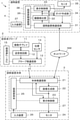
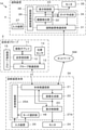
- FIG. 1 shows the configuration of the ultrasonic diagnostic system 1 according to the first embodiment of the present invention.
- the ultrasonic diagnostic system 1 includes an ultrasonic probe 2, a diagnostic device main body 3, and a remote device 4.
- the ultrasonic probe 2 and the diagnostic device main body 3 are connected to each other by wireless communication.
- the diagnostic device main body 3 and the remote device 4 are connected to each other via a network NW.
- Wireless communication or wired communication is used as the connection method between the diagnostic device main body 3 and the network NW and the connection method between the remote device 4 and the network NW.
- the ultrasonic probe 2 includes an oscillator array 11, and a transmission / reception circuit 12 and a probe-side communication unit 13 are sequentially connected to the oscillator array 11. Further, a position sensor 14 is attached to the ultrasonic probe 2, and the position sensor 14 is connected to the probe-side communication unit 13. Further, the probe control unit 15 is connected to the transmission / reception circuit 12 and the probe side communication unit 13.
- the diagnostic device main body 3 has a main body side communication unit 21, and an image generation unit 22, a display control unit 23, and a monitor 24 are sequentially connected to the main body side communication unit 21. Further, the display control unit 23 is connected to the main body side communication unit 21.
- the main body control unit 25 is connected to the main body side communication unit 21, the image generation unit 22, and the display control unit 23. Further, the input device 26 is connected to the main body control unit 25. Further, the main body side processor 27 is configured by the main body side communication unit 21, the image generation unit 22, the display control unit 23, and the main body control unit 25.
- the remote device 4 includes a remote device side communication unit 31, and an organ detection unit 32, a display control unit 33, and a guide creation unit 34 are connected to the remote device side communication unit 31.
- the organ detection unit 32 is connected to the display control unit 33 and the guide creation unit 34.
- the guide creation unit 34 is connected to the remote device side communication unit 31.
- a monitor 35 is connected to the display control unit 33.
- the remote device control unit 36 is connected to the remote device side communication unit 31, the organ detection unit 32, the display control unit 33, and the guide creation unit 34.
- the input device 37 is connected to the remote device control unit 36.
- the remote device side processor 38 is configured by the remote device side communication unit 31, the organ detection unit 32, the display control unit 33, the guide creation unit 34, and the remote device control unit 36.
- the oscillator array 11 of the ultrasonic probe 2 shown in FIG. 1 has a plurality of oscillators arranged one-dimensionally or two-dimensionally. Each of these oscillators transmits ultrasonic waves according to the drive signal supplied from the transmission / reception circuit 12, receives ultrasonic echoes from the subject, and outputs a signal based on the ultrasonic echoes.
- Each oscillator includes, for example, a piezoelectric ceramic represented by PZT (Lead Zirconate Titanate), a polymer piezoelectric element represented by PVDF (Poly Vinylidene Di Fluoride), and PMN-PT (PMN-PT).
- Lead Magnesium Niobate-Lead Titanate It is composed by forming electrodes at both ends of a piezoelectric body made of a piezoelectric single crystal represented by (lead magnesiumidene fluoride-lead titanate solid solution).
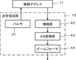
- the transmission / reception circuit 12 transmits ultrasonic waves from the vibrator array 11 and generates a sound line signal based on the received signal acquired by the vibrator array 11 under the control of the probe control unit 15.
- the transmission / reception circuit 12 includes a pulser 41 connected to the oscillator array 11, an amplification unit 42 sequentially connected in series from the oscillator array 11, an AD (Analog Digital) conversion unit 43, and a beam former. Has 44.
- the pulser 41 includes, for example, a plurality of pulse generators, and is transmitted from the plurality of oscillators of the oscillator array 11 based on a transmission delay pattern selected according to a control signal from the probe control unit 15.
- Each drive signal is supplied to a plurality of oscillators by adjusting the delay amount so that the ultrasonic waves form an ultrasonic beam.
- a pulsed or continuous wave voltage is applied to the electrodes of the vibrator of the vibrator array 11
- the piezoelectric body expands and contracts, and pulsed or continuous wave ultrasonic waves are generated from each vibrator.
- An ultrasonic beam is formed from the combined waves of those ultrasonic waves.
- the transmitted ultrasonic beam is reflected by, for example, a target such as a site of a subject, and propagates toward the vibrator array 11 of the ultrasonic probe 2.
- the ultrasonic echo propagating toward the oscillator array 11 in this way is received by each oscillator constituting the oscillator array 11.
- each oscillator constituting the oscillator array 11 expands and contracts by receiving the propagating ultrasonic echo to generate a received signal which is an electric signal, and these received signals are transmitted to the amplification unit 42. Output.
- the amplification unit 42 amplifies the signal input from each of the oscillators constituting the oscillator array 11, and transmits the amplified signal to the AD conversion unit 43.
- the AD conversion unit 43 converts the signal transmitted from the amplification unit 42 into digital reception data, and transmits these reception data to the beam former 44.
- the beam former 44 follows the sound velocity or sound velocity distribution set based on the reception delay pattern selected according to the control signal from the probe control unit 15, and the beam former 44 for each received data converted by the AD conversion unit 43, respectively.
- the so-called reception focus processing is performed by giving a delay of and adding. By this reception focus processing, each received data converted by the AD conversion unit 43 is phase-adjusted and added, and a sound line signal in which the focus of the ultrasonic echo is narrowed down is acquired.
- the probe-side communication unit 13 includes an antenna or the like for transmitting and receiving radio waves, and under the control of the probe control unit 15, wirelessly communicates with the main body-side communication unit 21 of the diagnostic device main body 3. At this time, the probe-side communication unit 13 generates a transmission signal representing the sound line signal by modulating the carrier based on the sound line signal generated by the transmission / reception circuit 12, and uses the generated transmission signal as a diagnostic device. Wireless transmission is performed to the main body side communication unit 21 of the main body 3.
- ASK Amplitude Shift Keying: quadrature shift keying
- PSK Phase Shift Keying: phase shift keying
- QPSK Quadrature Phase Shift Keying: quadrature shift keying
- 16QAM 16 quadrature phase shift modulation
- the probe control unit 15 controls each unit of the ultrasonic probe 2 based on a program stored in advance.
- the position sensor 14 is attached to the ultrasonic probe 2 and detects the measurement position of the ultrasonic probe 2.
- the position sensor 14 can include, for example, a magnetic sensor, a gyro sensor, an acceleration sensor, or the like.
- the ultrasonic probe 2 has a built-in battery that supplies electric power to each part of the ultrasonic probe 2.
- the diagnostic device main body 3 is a portable, so-called handheld device, and is composed of, for example, a thin computer called a tablet terminal.
- the main body side communication unit 21 of the diagnostic apparatus main body 3 includes an antenna and the like for transmitting and receiving radio waves as in the probe side communication unit 13, and the ultrasonic probe 2 is controlled by the main body control unit 25. Wireless communication with the probe side communication unit 13 and communication with the remote device side communication unit 31 of the remote device 4 via the network NW. Wireless communication or wired communication is used for the connection between the main body side communication unit 21 and the network NW.
- the main body side communication unit 21 demodulates the transmission signal wirelessly transmitted from the probe side communication unit 13 to obtain a sound line signal during wireless communication with the probe side communication unit 13.
- the main body side communication unit 21 sends the obtained sound line signal to the image generation unit 22.
- the main body side communication unit 21 is a transmission signal representing a control signal or the like by modulating the carrier based on the control information for controlling the ultrasonic probe 2 input by the measurer via the input device 26. Is generated, and the generated transmission signal is wirelessly transmitted to the probe-side communication unit 13.
- the carrier modulation method for example, ASK, PSK, QPSK, 16QAM, or the like is used in the same manner as the modulation method used by the probe-side communication unit 13.
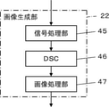
- the image generation unit 22 has a configuration in which a signal processing unit 45, a DSC (Digital Scan Converter) 46, and an image processing unit 47 are sequentially connected in series.
- the signal processing unit 45 corrects the attenuation of the sound line signal transmitted from the main body side communication unit 21 by the distance according to the depth of the reflection position of the ultrasonic wave, and then performs the envelope detection process.
- a B-mode image signal which is tomographic image information about the tissue in the subject, is generated.
- the DSC 46 converts the B-mode image signal generated by the signal processing unit 45 into an image signal according to a normal television signal scanning method (raster conversion).
- the image processing unit 47 performs various necessary image processing such as gradation processing on the B mode image signal input from the DSC 46, and then communicates the B mode image signal on the main body side in response to a command from the main body control unit 25. It is sent to the unit 21 or the display control unit 23.
- the B-mode image signal that has been image-processed by the image processing unit 47 is simply referred to as an ultrasonic image.
- the display control unit 23 performs predetermined processing on the ultrasonic image or the like generated by the image generation unit 22 and displays it on the monitor 24.
- the monitor 24 performs various displays under the control of the display control unit 23.
- the monitor 24 includes, for example, a display device such as an LCD (Liquid Crystal Display) and an organic EL display (Organic Electroluminescence Display).
- the input device 26 is for the measurer to perform an input operation, and includes a touch panel arranged on the monitor 24, a button (not shown), a switch (not shown), and the like.
- the main body control unit 25 controls each part of the diagnostic apparatus main body 3 based on a control program or the like stored in advance.
- the main body side processor 27 including the image generation unit 22, the display control unit 23, and the main body control unit 25 is derived from a CPU (Central Processing Unit) and a control program for causing the CPU to perform various processes. Although it is composed, FPGA (Field Programmable Gate Array: Feed Programmable Gate Array), DSP (Digital Signal Processor: Digital Signal Processor), ASIC (Application Specific Integrated Circuit: Application Specific Integrated Circuit), GPU (Graphics Processing Unit: Graphic) It may be configured by using a processing unit) or another IC (Integrated Circuit), or may be configured by combining them.
- a CPU Central Processing Unit
- DSP Digital Signal Processor
- ASIC Application Specific Integrated Circuit
- GPU Graphic
- the image generation unit 22, the display control unit 23, and the main body control unit 25 of the main body side processor 27 can be partially or wholly integrated into one CPU or the like.
- the remote device 4 is installed in, for example, a hospital or the like, and is a doctor who is skilled in measuring the organ of the subject in order to support the measurer who measures the organ of the subject in the field of home nursing away from the hospital. It is operated by an operator such as.
- the remote device side communication unit 31 of the remote device 4 includes an antenna and the like for transmitting and receiving radio waves, like the probe side communication unit 13 and the main body side communication unit 21, and is on the main body side via the network NW. Communicates with the communication unit 21. Wireless communication or wired communication is used for the connection between the remote device side communication unit 31 and the network NW.
- the remote device side communication unit 31 controls the remote device 4 generated by the main body control unit 25 and the ultrasonic image generated by the image generation unit 22 from the main body side communication unit 21 via the network NW. Receive instruction information, etc.
- the organ detection unit 32 detects the organ of the subject reflected in the ultrasonic image by analyzing the ultrasonic image generated by the image generation unit 22.
- the organ detection unit 32 is a machine using, for example, a so-called deep learning method, a so-called template matching method, an SVM (Support vector machine), an adaboost, or the like as a method for detecting an organ of a subject.
- Learning method Machine learning method described in Csurka et al .: Visual Categorization with Bags of Keypoints, Proc. Of ECCV Workshop on Statistical Learning in Computer Vision, pp.59-74 (2004) can be used.
- the display control unit 33 determines the ultrasonic image generated by the image generation unit 22 and the measurement position information of the ultrasonic probe 2 detected by the position sensor 14 and the like. It is processed and displayed on the monitor 35 of the remote device 4.
- the monitor 35 performs various displays under the control of the display control unit 33. Similar to the monitor 24, the monitor 35 includes a display device such as an LCD or an organic EL display.
- the guide creation unit 34 measures the operation of the ultrasonic probe 2 by using the image of the organ of the subject detected by the organ detection unit 32 and the information of the measurement position of the ultrasonic probe 2 detected by the position sensor 14. Create guide information to guide people.
- the guide information created by the guide creation unit 34 is transmitted to the monitor 24 of the diagnostic device main body 3 via the remote device side communication unit 31, the network NW, the main body side communication unit 21, the image generation unit 22, and the display control unit 23. Is displayed.
- the input device 37 is for the operator of the remote device 4 to perform an input operation, and can be configured to include a keyboard, a mouse, a trackball, a touch pad, a touch panel, and the like.
- the remote device control unit 36 controls each unit of the remote device 4 based on a control program or the like stored in advance.
- the remote device side processor 38 including the remote device side communication unit 31, the organ detection unit 32, the display control unit 33, and the guide creation unit 34 is composed of a CPU and a control program for causing the CPU to perform various processes. However, it may be configured by using FPGA, DSP, ASIC, GPU, or other IC, or may be configured by combining them. Further, the remote device side communication unit 31, the organ detection unit 32, the display control unit 33, and the guide creation unit 34 of the remote device side processor 38 are configured to be partially or wholly integrated into one CPU or the like. You can also.
- an ultrasonic probe for taking an ultrasonic image while being placed on the body surface of a subject and an ultrasonic probe while being inserted in the subject are used as general types of ultrasonic probes.
- An ultrasonic probe called an intracorporeal probe for taking an image is known.
- an example in which the ultrasonic probe 2 in the first embodiment of the present invention is an intrabody cavity probe will be described, but an ultrasonic image is taken while being placed on the body surface of the subject. The same operation is performed when the ultrasonic probe is used.
- the measurer measures the organ of the subject using the ultrasonic probe 2 and the diagnostic device main body 3, and the subject is measured at a remote location such as a hospital with respect to the position of the measurer. It is assumed that the remote device 4 is operated by an operator such as a doctor who is skilled in measuring the organs of the above.
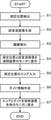
- step S1 the ultrasonic probe 2 is inserted into the subject by the measurer, and the ultrasonic probe 2 is moved to the measurement position for measuring the target organ. At this time, the position sensor 14 attached to the ultrasonic probe 2 detects the measurement position of the ultrasonic probe 2.
- step S2 an ultrasonic image is taken with the ultrasonic probe 2 placed at the measurement position detected in step S1.
- an ultrasonic beam is transmitted into the subject from a plurality of oscillators of the oscillator array 11 according to a drive signal from the pulsar 41 of the transmission / reception circuit 12, and each oscillator that receives the ultrasonic echo from the subject.
- the received signal is output to the amplification unit 42 of the transmission / reception circuit 12.
- the received signal is amplified by the amplification unit 42, AD-converted by the AD conversion unit 43, and then phase-adjusted and added by the beam former 44 to generate a sound line signal.
- This sound line signal is wirelessly communicated from the probe-side communication unit 13 to the main body-side communication unit 21 and transmitted to the image generation unit 22.
- the sound line signal is generated in the image generation unit 22, and the image generation unit 22 generates an ultrasonic image by performing various processes on the sound line signal.
- the ultrasonic image generated in this way is sent to the organ detection unit 32 and the display control unit 33 via the main body side communication unit 21, the network NW, and the remote device side communication unit 31.
- the organ detection unit 32 detects the organ of the subject contained in the ultrasonic image by analyzing the ultrasonic image generated in step S2. At this time, the organ detection unit 32 can detect an organ by using, for example, a deep learning method, a template matching method, a machine learning method using SVM, adaboost, or the like.
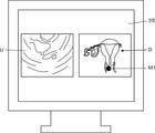
- step S4 the measurement position of the ultrasonic probe 2 detected in step S1 and the ultrasonic image U generated in step S2 are displayed on the monitor 35 of the remote device 4.
- the probe mark M1 indicating the position of the tip of the ultrasonic probe 2 is detected in step S1 by being superimposed and displayed on the schematic diagram D of the organ of the subject detected in step S3. The measurement position of the ultrasonic probe 2 is shown.
- the remote device control unit 36 stores the schematic diagrams of the plurality of organs in advance, and selects the schematic diagram D of the organ of the subject detected in step S3 from the schematic diagrams of the plurality of organs. Further, based on the information of the measurement position detected in step S1, the probe mark M1 can be arranged at the position on the schematic diagram D corresponding to the measurement position.
- step S5 the operator detects the organ of the subject detected in step S3 via the input device 37 of the remote device 4 in step S1 with respect to the optimum position when measuring using the ultrasonic probe 2.
- the score of the measurement position of the ultrasonic probe 2 is input.
- the operator of the remote device 4 observes the measurement position of the ultrasonic probe 2 and the ultrasonic image U displayed on the monitor 35 of the remote device 4 in step S4, so that the current ultrasonic probe 2 can be operated. Determine how close the measurement position is to the optimum position and enter the score.
- This score is an index indicating the optimum degree of the measurement position of the ultrasonic probe 2 in which the ultrasonic image U including the organ is taken in the measurement of the organ detected in step S3. For example, the closer the measurement position of the ultrasonic probe 2 from which the ultrasonic image U including the organ detected in step S3 is to the optimum position for measuring the organ, the larger the score is input, and the farther from the optimum position. A small score is entered.
- a numerical value can be input as the score. Further, for example, by assigning characters such as A, B, C, ... In the order in which the measurement positions are close to the optimum positions, these characters can be input as the score.
- the score information input in this way is sent to the monitor 24 of the diagnostic device main body 3 via the remote device side communication unit 31, the network NW, the main body side communication unit 21, the image generation unit 22, and the display control unit 23. Will be done.
- the guide creation unit 34 operates the ultrasonic probe 2 by using the information indicating the measurement position of the ultrasonic probe 2 detected in step S1 and the image of the organ of the subject detected in step S3. Create guide information to guide the measurer.
- the guide creating unit 34 provides guide information to guide the measurer in the direction in which the ultrasonic probe 2 should be moved in order to visualize the organ detected in step S3 more clearly in the ultrasonic image U. Can be created.
- the guide information created in this way is sent to the monitor 24 via the remote device side communication unit 31, the network NW, the main body side communication unit 21, the image generation unit 22, and the display control unit 23.
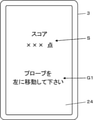
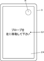
- step S7 based on the score information input in step S5 and the guide information created in step S6, the score S and the guide G1 are transferred to the monitor 24 of the diagnostic apparatus main body 3 as shown in FIG. Is displayed.
- a guide G1 consisting of a numerical value representing the score S and the text "Please move the probe to the left" is displayed on the monitor 24.
- the measurer who measures the organ of the subject moves the ultrasonic probe 2 while checking the score S and the guide G1 displayed in this way, so that the optimum measurement position for measuring the target organ is obtained. It is possible to take an ultrasonic image U by arranging the ultrasonic probe 2 in the above.
- a handheld type diagnostic device main body and an ultrasonic diagnostic device having an ultrasonic probe may be used to perform measurement in a subject at a place away from the hospital, such as a home nursing site. be.
- a place away from the hospital such as a home nursing site.
- the measurement inside the subject is smooth because the measurer with low skill in the ultrasonic diagnostic apparatus performs the measurement inside the subject. Sometimes it wasn't done.
- the measurer needs to place the ultrasonic probe at the optimum measurement position for the measurement of the target site while checking the ultrasonic image currently being taken.
- the subject sometimes saw the ultrasound image.
- the score S of the measurement position of the ultrasonic probe 2 with respect to the optimum position when the target organ is measured by the ultrasonic probe 2 is determined by a doctor or the like. Since it can be input by a skilled operator, the input score S is displayed on the monitor 24, and the generated ultrasonic image U is not displayed on the monitor 24, the captured ultrasonic image U is covered. Even a person with a low skill level can smoothly measure the target organ in the subject by using the handheld type diagnostic apparatus main body 3 while preventing the sample from being seen.
- an ultrasonic probe for taking an ultrasonic image U while being placed on the body surface of the subject can be used. Even in this case, while preventing the captured ultrasonic image U from being seen in the subject, even a less skilled measurer can measure the target organ in the subject using the handheld type diagnostic apparatus main body 3. It can be done smoothly. However, when an intrabody probe is used as the ultrasonic probe 2, it is difficult for the measurer to directly confirm the tip of the ultrasonic probe 2 because the ultrasonic probe 2 is inserted into the subject. Therefore, the present invention is more useful.
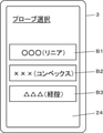
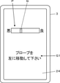
- the main body control unit 25 displays the buttons B1, B2, and B3 for selecting the type of the ultrasonic probe 2 on the monitor 24, and the body cavity is displayed by the measurer via the input device 26.
- the button B3 corresponding to the inner probe is selected, the communication unit 21 on the main body side is requested to transmit the measurement position information detected in step S1 and the ultrasonic image U generated in step S2 to the remote device 4. You can send commands.
- the button B1 for selecting the “ ⁇ (linear)” ultrasonic probe the button B2 for selecting the “XXX (convex)” ultrasonic probe, and the “ ⁇ ” button B2.
- (Transvaginal) ”button B3 for selecting the ultrasonic probe is displayed on the monitor 24.
- " ⁇ ", "XXX” and “ ⁇ ” are identifiers of the ultrasonic probe 2 such as the model number and the name of the ultrasonic probe 2.
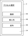
- the main body control unit 25 when it is determined by the main body control unit 25 that the preset for the examination using the intracavitary probe is selected, the main body control unit 25 is generated with the measurement position information detected in step S1 and in step S2. It is also possible to send a command to the communication unit 21 on the main body side to transmit the ultrasonic image U to the remote device 4.
- the preset is an imaging condition such as a gain when generating an ultrasonic image U and an ultrasonic image U according to the type of examination such as an abdominal examination, a gynecological examination, and an obstetrics examination. It is a set of preset conditions including image display conditions such as contrast when performing.
- the main body control unit 25 has, for example, a button B4 for selecting a preset for the abdomen, a button B5 for selecting a preset for gynecology, and a button for selecting a preset for obstetrics.
- the measurement detected in step S1 when B6 is displayed on the monitor 24 and the button B5 for selecting a gynecological preset using an intracoelomic probe is selected by the measurer via the input device 26.
- a command can be sent to the communication unit 21 on the main body side to transmit the position information and the ultrasonic image U generated in step S2 to the remote device 4.
- step S7 an example in which the score S is displayed as a numerical value on the monitor 24 is described, but the display method of the score S is not particularly limited to this.
- the main body control unit 25 displays the score mark R for indicating the score S in color on the monitor 24, and changes the display color of the score mark R according to the value of the score S to obtain the score.
- S can be displayed on the monitor 24 by color coding.
- the main body control unit 25 assigns blue, yellow, and red in the order in which the measurement position is closer to the optimum position, and sets the score mark R in blue according to the input operation of the operator via the input device 37 of the remote device 4. , Can be displayed in yellow or red.
- the main body control unit 25 can change the display color of the entire monitor 24 of the diagnostic apparatus main body 3, that is, the background, instead of changing the color of the score mark R.
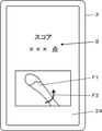
- the main body control unit 25 can also express the score S by the meter P in response to the input operation of the operator via the input device 37 of the remote device 4.
- the meter P includes the needle portion Q, and the closer the needle portion Q is to the “evil” on the left, the lower the score S, and the needle portion Q is on the right. The closer the position is to "good", the higher the score S is.
- the guide G1 consisting of the text "Please move the probe to the left” is displayed on the monitor 24, but the guide G1 is to move the ultrasonic probe 2 up / down or left / right. It may include not only the content that prompts the user to rotate the ultrasonic probe 2 in a specific direction but also the content that prompts the ultrasonic probe 2 to rotate in a specific direction.
- the guide G1 composed of text is not limited to being displayed on the monitor 24, and for example, as shown in FIG. 11, an image F1 showing the ultrasonic probe 2 and a direction in which the ultrasonic probe 2 should be rotated are shown.
- the arrow F2 may also be displayed on the monitor 24 as a guide to the measurer.
- an arrow indicating the direction in which the ultrasonic probe should be moved may be displayed on the monitor 24 instead of the arrow F2 indicating the direction in which the ultrasonic probe 2 should be rotated.
- the image F1 and the arrow F1 in which the direction in which the ultrasonic probe 2 should be rotated or moved indicates the ultrasonic probe 2 are displayed on the monitor 24, so that the measurer can see the ultrasonic probe 2 in the direction in which the ultrasonic probe 2 is to be rotated or moved. It is possible to more clearly grasp the direction to rotate or the direction to move.
- the guide information is created in step S6 and the guide G1 based on the guide information is displayed on the monitor 24 in step S7, only the score S of the score S and the guide G1 may be displayed on the monitor 24. .. Even in this case, the measurer moves the ultrasonic probe 2 while checking the score S displayed on the monitor 24 of the diagnostic apparatus main body 3, so that the ultrasonic probe is located at the optimum measurement position for the measurement of the target portion. It is possible to arrange 2.
- the probe mark M1 indicating the measurement position of the ultrasonic probe 2 is a schematic of the organ.
- the method of displaying the measurement position of the ultrasonic probe 2 on the monitor 35 of the remote device 4 is not particularly limited to this.
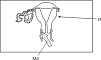
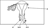
- the remote device control unit 36 calculates the orientation of the ultrasonic probe 2 with respect to the organ based on the measurement position of the ultrasonic probe 2 detected in step S1 and the image of the organ detected in step S3. As shown in 12, an arrow-shaped probe mark M2 representing both the calculated orientation of the ultrasonic probe 2 and its measurement position can be superimposed on the schematic diagram D of the organ. As a result, the operator of the remote device 4 can easily grasp the position and orientation of the ultrasonic probe 2 with respect to the target organ and input a more accurate score S.
- the remote device control unit 36 can move the tip of the ultrasonic probe 2 from the position of the rear end portion of the ultrasonic probe 2.
- the direction toward the position of the portion can also be calculated as the direction of the ultrasonic probe 2.
- the position sensor 14 includes the gyro sensor
- the orientation of the ultrasonic probe 2 can be detected by using the gyro sensor.
- a comment for supporting the measurer who measures the organ of the subject is input by the operator via the input device 37 of the remote device 4, and the input comment is displayed on the monitor 24 of the diagnostic device main body 3.
- the main body control unit 25 creates a comment input by the operator by the guide creation unit 34, for example, making the display color of the guide G1 lighter than the display color of the comment input by the operator. It can be displayed on the monitor 24 with priority over the guided guide G1.
- the main body control unit 25 Analyzes the comment input by the operator and determines whether or not the comment is a content that guides the operation of the ultrasonic probe 2 such as "Please move the ultrasonic probe to the right". be able to.
- the main body control unit 25 diagnoses the comment input by the operator instead of, for example, the guide G1. It can be displayed on the monitor 24 of the device main body 3.
- the analysis of the comment input by the operator may be transmitted to the diagnostic device main body 3A after being performed by the remote device control unit 36 of the remote device 4, and diagnosed after being performed by a server device (not shown). It may be transmitted to the device main body 3A. In this way, the comment by the operator of the remote device 4 is displayed on the monitor 24 of the diagnostic device main body 3, so that it is possible to more accurately support the measurer.
- the remote device control unit 36 stores the schematic diagram D of the plurality of organs
- the diagnostic device main body 3 stores the schematic diagram D of the plurality of organs (not shown).
- a schematic diagram D of an organ provided with a memory and detected by the organ detection unit 32 according to a command from the remote device control unit 36 is shown in the main body side communication unit 21, network NW, remote device side communication unit 31 and display control unit 33. It can also be displayed on the monitor 35 via.
- a server device for storing a schematic diagram D of a plurality of organs may be provided, and the schematic diagram D may be transmitted from this server device to the remote device 4.
- a reconstructed image obtained by prescanning the subject may be used.
- the pre-scan is a scan performed to roughly confirm the inside of the subject using the ultrasonic probe 2 used for the measurement before the measurement of the organ of the subject is performed.
- the remote device control unit 36 uses the technique disclosed in Japanese Patent Application Laid-Open No. 2002-209890 to obtain three-dimensional voxel data of a target organ based on a multi-frame ultrasonic image U taken. By generating, a reconstructed image can be generated.
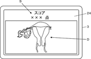
- Embodiment 2 In the first embodiment, an example is shown in which a guide G1 composed of a numerical value representing a score S and a text is displayed on the monitor 24, but it is possible to prevent the ultrasonic image U from being seen on the subject and to measure the person. In order to perform the measurement more smoothly, the schematic diagram D of the organ currently being measured may be displayed on the monitor 24.
- FIG. 13 shows the configuration of the ultrasonic diagnostic system 1A according to the second embodiment.
- the ultrasonic diagnostic system 1A includes the diagnostic device main body 3A instead of the diagnostic device main body 3 in the ultrasonic diagnostic system 1 of the first embodiment shown in FIG.
- the diagnostic device main body 3A is the diagnostic device main body 3 according to the first embodiment, in which the mode selection unit 48 is added and the main body control unit 25 is provided instead of the main body control unit 25.
- the mode selection unit 48 is connected to the main body control unit 25A and the input device 26. Further, instead of the main body side processor 27, the main body side processor 27A including the mode selection unit 48 is configured.
- the main body control unit 25 stores a schematic diagram of a plurality of organs, selects a schematic diagram of the organ detected by the organ detection unit 32 of the remote device 4, and as shown in FIG. 13, the schematic diagram D thereof. Is displayed on the monitor 24. In FIG. 14, a schematic diagram D of the uterus of the subject is displayed on the monitor 24 together with the score S. By confirming the schematic diagram D displayed on the monitor 24, the measurer can easily grasp which organ's ultrasonic image U is actually being photographed.
- the mode selection unit 48 has a first mode in which the ultrasonic image U is displayed on the monitor 24 as shown in FIG. 15 based on the input operation of the measurer via the input device 26 of the diagnostic device main body 3A.
- the mode selection unit 48 selects the first mode when there is a low possibility that the ultrasonic image U will be seen in the subject based on the input operation of the measurer and the ultrasonic image U is desired to be confirmed.
- the second mode can be selected when there is a high possibility that the ultrasonic image U will be seen in the subject.
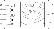
- operation icons J1 to J5 for operating the ultrasonic diagnostic system 1A may be displayed on the monitor 24.
- the operation icon J1 is for switching the inspection mode
- the operation icon J2 is for saving a plurality of frames of ultrasonic images U continuously generated within a certain period of time.
- J3 is for freeze-displaying the ultrasonic image U on the monitor 24,
- the operation icon J4 is for changing the so-called gain and depth, and the operation icon J5 is a plurality of other not shown. This is for displaying the operation icon on the monitor 24.
- the measurer confirms the schematic diagram D of the organ displayed on the monitor 24, and the organ currently being measured can be easily measured. Therefore, the measurer can measure the organ of the subject more smoothly.
- the measurer since the first mode in which the ultrasonic image U is displayed and the second mode in which the schematic diagram D and the score S of the organ are displayed are switched by the input operation of the measurer via the input device 26, the subject is switched. It is possible for the measurer to confirm the ultrasonic image U while preventing the ultrasonic image U from being seen, so that the measurer can measure the organ of the subject more smoothly. Can be done.
- the main body control unit 25A stores the schematic diagram D of the plurality of organs.
- the remote device control unit 36 of the remote device 4 stores the schematic diagram D of the plurality of organs. You may.
- a schematic diagram D of the organ detected by the organ detection unit 32 by a command from the main body control unit 25A is displayed from the remote device control unit 36 to the remote device side communication unit 31, the network NW, and the main body side communication. It can be displayed on the monitor 24 via the unit 21, the image generation unit 22, and the display control unit 23.
- a reconstructed image obtained by prescanning the subject may be used.
- the main body control unit 25A generates three-dimensional voxel data of a target organ based on a multi-frame ultrasonic image U taken by using the technique disclosed in Japanese Patent Application Laid-Open No. 2002-209890. By doing so, a reconstructed image can be generated.
- the remote device control unit 36 of the remote device 4 may generate the reconstructed image.
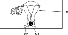
- the measurement position of the ultrasonic probe 2 detected by the position sensor 14 can be displayed on the monitor 24 by superimposing it on the schematic diagram D of the organ.
- the main body control unit 25A can superimpose the probe mark M1 indicating the position of the tip portion of the ultrasonic probe 2 on the schematic diagram D of the organ.
- the measurer can easily grasp the position of the ultrasonic probe 2 with respect to the target organ.
- the guide creation unit 34 can indicate the direction in which the ultrasonic probe 2 should be moved in order to accurately measure the target organ by the arrow G2.
- the measurer can easily move the ultrasonic probe 2 to the optimum measurement position for measuring the target organ.
- the main body control unit 25A determines the orientation of the ultrasonic probe 2 with respect to the organ, for example, based on the image of the organ detected by the organ detection unit 32 and the measurement position of the ultrasonic probe 2 detected by the position sensor 14. As shown in FIG. 17, an arrow-shaped probe mark M2 representing both the calculated orientation of the ultrasonic probe 2 and its measurement position can be superimposed on the schematic diagram D of the organ.
- an orientation mark is often placed on the side of the ultrasonic probe so that the measurer can grasp the rotation direction of the ultrasonic probe.
- a rotation direction mark K may be displayed on the right side or the left side of the probe mark M2 to indicate whether the orientation mark is arranged on the left or right side of the probe mark M2 arranged on the schematic diagram D.
- the main body control unit 25A stores, for example, which of both ends of the ultrasonic image U in the direction orthogonal to the depth direction corresponds to the arrangement position of the orientation mark, and the image generation unit 22.
- the position of the rotation direction mark K arranged on the schematic diagram D can be calculated.
- the star-shaped rotation direction mark K is shown in FIG. 17, the shape of the rotation direction mark K is not limited to this, and may have any shape.
- both the orientation of the ultrasonic probe 2 and the measurement position thereof are indicated by the probe mark M2, so that the measurer can easily grasp the position and orientation of the ultrasonic probe 2 with respect to the target organ. can.
- the main body control unit 25A can move the front end portion of the ultrasonic probe 2 from the position of the rear end portion of the ultrasonic probe 2.
- the direction toward the position of can be calculated as the direction of the ultrasonic probe 2.
- the guide creating unit 34 should rotate the ultrasonic probe 2 in order to accurately measure the target organ.
- the measurer can easily rotate the ultrasonic probe 2 at an optimum angle for measuring the target organ.
- the ultrasonic waves as shown in FIG. 11 are placed at the positions on the schematic diagram D corresponding to the measurement positions detected by the position sensor 14.
- the image F1 of the probe 2 can also be displayed.
- 1,1A ultrasonic diagnostic system 2 ultrasonic probe, 3,3A diagnostic device main body, 4 remote device, 11 oscillator array, 12 transmission / reception circuit, 13 probe side communication unit, 14 position sensor, 15 probe control unit, 21 main unit Side communication unit, 22 image generation unit, 23 display control unit, 24,35 monitor, 25,25A main unit control unit, 26,37 input device, 27 main unit side processor, 31 remote device side communication unit, 32 organ detection unit, 33 Display control unit, 34 guide creation unit, 36 remote device control unit, 38 remote device side processor, 41 pulser, 42 amplification unit, 43 AD conversion unit, 44 beam former, 45 signal processing unit, 46 DSC, 47 image processing unit, 48 Mode selection unit, B1 to B6 button, D schematic diagram, F1 image, F2, G2, G3 arrow, G1 guide, J1 to J5 operation icon, K rotation direction mark, M1, M2 probe mark, NW network, P meter, Q needle part, R score mark, S score, U ultrasonic image.
Abstract
超音波診断システム(1)は、超音波プローブ(2)と、ハンドヘルド型の診断装置本体(3)と、遠隔装置(4)とを備え、超音波プローブ(2)は、超音波プローブ(2)の測定位置を検出する位置センサ(14)を有し、診断装置本体(3)は、超音波画像を生成する画像生成部(22)とモニタ(24)とを有し、遠隔装置(4)は、超音波画像を解析して被検体の臓器を検出する臓器検出部(32)を有し、臓器検出部(32)により検出された臓器を超音波プローブ(2)により測定する際の最適位置に対する測定位置のスコアが、遠隔装置(4)に入力され、遠隔装置(4)から診断装置本体(3)に送信されてモニタ(24)に表示される。
Description
本発明は、ハンドヘルド型の診断装置本体を備えた超音波診断システムおよび超音波診断システムの制御方法に関する。
従来から、超音波診断装置を用いて被検体の断層を表す超音波画像を撮影することにより、被検体内の臓器の測定が行われている。超音波画像の撮影において、被検体内への超音波ビームの送信と被検体内で反射した超音波エコーの受信を行うために、超音波プローブが用いられる。このような超音波プローブとしては、例えば、被検体の体表上に配置された状態で被検体内に超音波ビームの送信を行う超音波プローブと、被検体内に挿入された状態で被検体内に超音波ビームの送信を行ういわゆる体腔内プローブと呼ばれる超音波プローブが知られている。測定者は、超音波プローブを被検体の体表上または被検体内の適切な測定位置に移動させることにより、被検体内の目的の臓器の超音波画像を撮影し、その臓器の測定を行う。
このように、測定者が観察したい被検体内の臓器に対応した適切な測定位置に超音波プローブを配置することは、熟練度の低い測定者にとって難しい場合がある。そのため、例えば特許文献1に開示されているように、測定者が超音波画像を撮影する際の支援を行う超音波診断装置が開発されている。特許文献1の超音波診断装置では、熟練者が予め撮影した超音波画像と、その超音波画像が撮影された際の超音波プローブの位置情報が測定者に向けて表示される。
ところで、いわゆるタブレット型端末等の薄型のコンピュータからなるいわゆるハンドヘルド型の診断装置本体と超音波プローブを有する、携帯型の超音波診断装置が開発されており、この携帯型の超音波診断装置を用いて、在宅看護の現場等の、病院から離れた場所で被検体内の測定が行われる場合がある。病院から離れた場所で被検体内の測定が行われる場合には、超音波診断装置に対する熟練度の低い測定者が被検体内の測定を行うことがあった。そこで、例えば特許文献1に開示されている技術を用いることが考えられるが、通常、ハンドヘルド型の診断装置本体に備えられているモニタは、いわゆる据え置き型の超音波診断装置に備えられているモニタと比較して小さいサイズを有しているため、測定者が行う超音波画像の撮影を支援するための情報を十分に表示できず、測定者が円滑に測定を行うことが困難なことがあった。
また、近年では、被検体に対して、被検体内の断層を表す超音波画像を見せたくないという要求が高まっている。しかしながら、特許文献1に開示されている技術を用いたとしても、被検体内の断層を表す超音波画像をモニタに表示せずに、被検体内の目的の臓器を測定するように支援を行うことは、困難であった。
本発明は、このような従来の問題点を解決するためになされたものであり、撮影された超音波画像が被検体に見られることを防ぎつつ、ハンドヘルド型の診断装置本体を用いて測定者が被検体内の臓器の測定を円滑に行うことができる超音波診断システムおよび超音波診断システムの制御方法を提供することを目的とする。
本発明に係る超音波診断システムは、超音波プローブと、超音波プローブに接続されたハンドヘルド型の診断装置本体と、診断装置本体に接続された遠隔装置とを備え、超音波プローブは、超音波プローブによる測定位置を検出する位置センサを有し、診断装置本体は、超音波プローブを用いて超音波ビームの送受信を行うことにより被検体の超音波画像を生成する画像生成部と、モニタとを有し、遠隔装置は、超音波画像を解析することにより撮像された被検体の臓器を検出する臓器検出部を有し、臓器検出部により検出された臓器を超音波プローブにより測定する際の最適位置に対する測定位置のスコアが、遠隔装置に入力され、遠隔装置から診断装置本体に送信されてモニタに表示されることを特徴とする。
診断装置本体は、画像生成部により生成された超音波画像と、超音波画像を撮像する際に位置センサにより検出された測定位置とを、遠隔装置に送信する本体側通信部を有し、遠隔装置は、スコアを診断装置本体に送信する遠隔装置側通信部を有することができる。
さらに、超音波プローブは、体腔内プローブであり、本体側通信部は、診断装置本体に体腔内プローブが接続された場合に、超音波画像と測定位置とを遠隔装置に送信することができる。
さらに、超音波プローブは、体腔内プローブであり、本体側通信部は、診断装置本体に体腔内プローブが接続された場合に、超音波画像と測定位置とを遠隔装置に送信することができる。
診断装置本体は、臓器検出部により検出された臓器の模式図をモニタに表示することができる。
また、診断装置本体は、模式図に重畳して位置センサにより検出された測定位置をモニタに表示することができる。
ここで、模式図は、被検体に対するプレスキャンにより取得された再構成像からなることができる。
また、診断装置本体は、模式図に重畳して位置センサにより検出された測定位置をモニタに表示することができる。
ここで、模式図は、被検体に対するプレスキャンにより取得された再構成像からなることができる。
遠隔装置は、超音波プローブを測定位置から最適位置に移動するためのガイドを作成するガイド作成部を有し、この場合に、ガイド作成部により作成されたガイドが、遠隔装置から診断装置本体に送信されてモニタに表示されることができる。
また、診断装置本体は、スコアを色分けによりモニタに表示することができる。
また、診断装置本体は、超音波画像がモニタに表示される第1モードと、模式図およびスコアがモニタに表示される第2モードのいずれかを選択するモード選択部を有することができる。
また、診断装置本体は、超音波画像がモニタに表示される第1モードと、模式図およびスコアがモニタに表示される第2モードのいずれかを選択するモード選択部を有することができる。
本発明の超音波診断システムの制御方法は、超音波プローブと、ハンドヘルド型の診断装置本体と、遠隔装置とを備える超音波診断システムの制御方法であって、超音波プローブによる測定位置を検出し、診断装置本体において、超音波プローブを用いて超音波ビームの送受信を行うことにより、被検体の超音波画像を生成し、遠隔装置において、超音波画像を解析することにより、撮像された被検体の臓器を検出し、検出された臓器を超音波プローブにより測定する際の最適位置に対する測定位置のスコアを遠隔装置から診断装置本体に送信し、スコアを診断装置本体のモニタに表示することを特徴とする。
本発明によれば、超音波診断システムが、超音波プローブと、超音波プローブに接続されたハンドヘルド型の診断装置本体と、診断装置本体に接続された遠隔装置とを備え、診断装置本体は、超音波プローブを用いて超音波ビームの送受信を行うことにより被検体の超音波画像を生成する画像生成部と、モニタとを有し、遠隔装置は、超音波画像を解析することにより撮像された被検体の臓器を検出する臓器検出部を有し、臓器検出部により検出された臓器を超音波プローブにより測定する際の最適位置に対する測定位置のスコアが、遠隔装置に入力され、遠隔装置から診断装置本体に送信されてモニタに表示されるため、撮影された超音波画像が被検体に見られることを防ぎつつ、ハンドヘルド型の診断装置本体を用いて測定者が被検体内の臓器の測定を円滑に行うことができる。
以下、この発明の実施の形態を添付図面に基づいて説明する。
以下に記載する構成要件の説明は、本発明の代表的な実施態様に基づいてなされるが、本発明はそのような実施態様に限定されるものではない。
なお、本明細書において、「~」を用いて表される数値範囲は、「~」の前後に記載される数値を下限値および上限値として含む範囲を意味する。
本明細書において、「同一」、「同じ」は、技術分野で一般的に許容される誤差範囲を含むものとする。
以下に記載する構成要件の説明は、本発明の代表的な実施態様に基づいてなされるが、本発明はそのような実施態様に限定されるものではない。
なお、本明細書において、「~」を用いて表される数値範囲は、「~」の前後に記載される数値を下限値および上限値として含む範囲を意味する。
本明細書において、「同一」、「同じ」は、技術分野で一般的に許容される誤差範囲を含むものとする。
実施の形態1
図1に、本発明の実施の形態1に係る超音波診断システム1の構成を示す。超音波診断システム1は、超音波プローブ2と、診断装置本体3と、遠隔装置4を備えている。超音波プローブ2と診断装置本体3は、無線通信により互いに接続されている。診断装置本体3と遠隔装置4は、ネットワークNWを介して互いに接続されている。なお、診断装置本体3とネットワークNWとの接続方法、および、遠隔装置4とネットワークNWとの接続方法は、無線通信または有線通信が用いられる。
図1に、本発明の実施の形態1に係る超音波診断システム1の構成を示す。超音波診断システム1は、超音波プローブ2と、診断装置本体3と、遠隔装置4を備えている。超音波プローブ2と診断装置本体3は、無線通信により互いに接続されている。診断装置本体3と遠隔装置4は、ネットワークNWを介して互いに接続されている。なお、診断装置本体3とネットワークNWとの接続方法、および、遠隔装置4とネットワークNWとの接続方法は、無線通信または有線通信が用いられる。
超音波プローブ2は、振動子アレイ11を備えており、振動子アレイ11に、送受信回路12およびプローブ側通信部13が順次接続されている。また、超音波プローブ2には、位置センサ14が取り付けられており、位置センサ14は、プローブ側通信部13に接続されている。また、送受信回路12およびプローブ側通信部13に、プローブ制御部15が接続されている。
診断装置本体3は、本体側通信部21を有しており、本体側通信部21に、画像生成部22、表示制御部23およびモニタ24が順次接続されている。また、表示制御部23は、本体側通信部21に接続されている。
本体側通信部21、画像生成部22および表示制御部23に、本体制御部25が接続されている。また、本体制御部25に入力装置26が接続されている。
また、本体側通信部21、画像生成部22、表示制御部23および本体制御部25により、本体側プロセッサ27が構成されている。
また、本体側通信部21、画像生成部22、表示制御部23および本体制御部25により、本体側プロセッサ27が構成されている。
遠隔装置4は、遠隔装置側通信部31を備えており、遠隔装置側通信部31に、臓器検出部32、表示制御部33およびガイド作成部34が接続されている。臓器検出部32は、表示制御部33およびガイド作成部34に接続されている。また、ガイド作成部34は、遠隔装置側通信部31に接続されている。また、表示制御部33に、モニタ35が接続されている。
また、遠隔装置側通信部31、臓器検出部32、表示制御部33およびガイド作成部34に、遠隔装置制御部36が接続されている。また、遠隔装置制御部36に、入力装置37が接続されている。
また、遠隔装置側通信部31、臓器検出部32、表示制御部33、ガイド作成部34および遠隔装置制御部36により、遠隔装置側プロセッサ38が構成されている。
また、遠隔装置側通信部31、臓器検出部32、表示制御部33、ガイド作成部34および遠隔装置制御部36により、遠隔装置側プロセッサ38が構成されている。
図1に示す超音波プローブ2の振動子アレイ11は、1次元または2次元に配列された複数の振動子を有している。これらの振動子は、それぞれ送受信回路12から供給される駆動信号にしたがって超音波を送信すると共に、被検体からの超音波エコーを受信して、超音波エコーに基づく信号を出力する。各振動子は、例えば、PZT(Lead Zirconate Titanate:チタン酸ジルコン酸鉛)に代表される圧電セラミック、PVDF(Poly Vinylidene Di Fluoride:ポリフッ化ビニリデン)に代表される高分子圧電素子およびPMN-PT(Lead Magnesium Niobate-Lead Titanate:マグネシウムニオブ酸鉛-チタン酸鉛固溶体)に代表される圧電単結晶等からなる圧電体の両端に電極を形成することにより構成される。
送受信回路12は、プローブ制御部15による制御の下で、振動子アレイ11から超音波を送信し且つ振動子アレイ11により取得された受信信号に基づいて音線信号を生成する。送受信回路12は、図2に示すように、振動子アレイ11に接続されるパルサ41と、振動子アレイ11から順次直列に接続される増幅部42、AD(Analog Digital)変換部43およびビームフォーマ44を有している。
パルサ41は、例えば、複数のパルス発生器を含んでおり、プローブ制御部15からの制御信号に応じて選択された送信遅延パターンに基づいて、振動子アレイ11の複数の振動子から送信される超音波が超音波ビームを形成するようにそれぞれの駆動信号を、遅延量を調節して複数の振動子に供給する。このように、振動子アレイ11の振動子の電極にパルス状または連続波状の電圧が印加されると、圧電体が伸縮し、それぞれの振動子からパルス状または連続波状の超音波が発生して、それらの超音波の合成波から、超音波ビームが形成される。
送信された超音波ビームは、例えば、被検体の部位等の対象において反射され、超音波プローブ2の振動子アレイ11に向かって伝搬する。このように振動子アレイ11に向かって伝搬する超音波エコーは、振動子アレイ11を構成するそれぞれの振動子により受信される。この際に、振動子アレイ11を構成するそれぞれの振動子は、伝搬する超音波エコーを受信することにより伸縮して、電気信号である受信信号を発生させ、これらの受信信号を増幅部42に出力する。
増幅部42は、振動子アレイ11を構成するそれぞれの振動子から入力された信号を増幅し、増幅した信号をAD変換部43に送信する。AD変換部43は、増幅部42から送信された信号をデジタルの受信データに変換し、これらの受信データをビームフォーマ44に送信する。ビームフォーマ44は、プローブ制御部15からの制御信号に応じて選択された受信遅延パターンに基づいて設定される音速または音速の分布に従い、AD変換部43により変換された各受信データに対してそれぞれの遅延を与えて加算することにより、いわゆる受信フォーカス処理を行う。この受信フォーカス処理により、AD変換部43で変換された各受信データが整相加算され且つ超音波エコーの焦点が絞り込まれた音線信号が取得される。
プローブ側通信部13は、電波の送信および受信を行うためのアンテナ等を含んでおり、プローブ制御部15の制御の下で、診断装置本体3の本体側通信部21と無線通信を行う。この際に、プローブ側通信部13は、送受信回路12により生成された音線信号に基づいてキャリアを変調することにより音線信号を表す伝送信号を生成し、生成された伝送信号を、診断装置本体3の本体側通信部21に無線送信する。
キャリアの変調方式としては、例えば、ASK(Amplitude Shift Keying:振幅偏移変調)、PSK(Phase Shift Keying:位相偏移変調)、QPSK(Quadrature Phase Shift Keying:四位相偏移変調)または16QAM(16 Quadrature Amplitude Modulation:16直角位相振幅変調)等が用いられる。
プローブ制御部15は、予め記憶しているプログラムに基づいて超音波プローブ2の各部の制御を行う。
位置センサ14は、超音波プローブ2に取り付けられており、超音波プローブ2の測定位置を検出する。位置センサ14は、例えば、磁気センサ、ジャイロセンサまたは加速度センサ等を含むことができる。
また、図示しないが、超音波プローブ2には、超音波プローブ2の各部に電力を供給するバッテリが内蔵されている。
位置センサ14は、超音波プローブ2に取り付けられており、超音波プローブ2の測定位置を検出する。位置センサ14は、例えば、磁気センサ、ジャイロセンサまたは加速度センサ等を含むことができる。
また、図示しないが、超音波プローブ2には、超音波プローブ2の各部に電力を供給するバッテリが内蔵されている。
診断装置本体3は、携帯可能な、いわゆるハンドヘルド型の装置であり、例えば、タブレット型端末と呼ばれる薄型のコンピュータにより構成される。
診断装置本体3の本体側通信部21は、プローブ側通信部13と同様に電波の送信および受信を行うためのアンテナ等を含んでおり、本体制御部25の制御の下で、超音波プローブ2のプローブ側通信部13との無線通信、および、ネットワークNWを介した遠隔装置4の遠隔装置側通信部31との通信を行う。本体側通信部21とネットワークNWとの接続には、無線通信または有線通信が用いられる。
本体側通信部21は、プローブ側通信部13との無線通信の際に、プローブ側通信部13から無線送信された伝送信号を復調して音線信号を得る。本体側通信部21は、得られた音線信号を画像生成部22に送出する。
また、本体側通信部21は、入力装置26を介して測定者により入力された、超音波プローブ2を制御するための制御情報等に基づいてキャリアを変調することにより制御信号等を表す伝送信号を生成し、生成された伝送信号をプローブ側通信部13に無線送信する。キャリアの変調方式としては、プローブ側通信部13により用いられる変調方式と同様に、例えば、ASK、PSK、QPSKまたは16QAM等が用いられる。
画像生成部22は、図3に示すように、信号処理部45、DSC(Digital Scan Converter:デジタルスキャンコンバータ)46および画像処理部47が順次直列に接続された構成を有している。
信号処理部45は、本体側通信部21から送出された音線信号に対し、超音波の反射位置の深度に応じて距離による減衰の補正を施した後、包絡線検波処理を施すことにより、被検体内の組織に関する断層画像情報であるBモード画像信号を生成する。
信号処理部45は、本体側通信部21から送出された音線信号に対し、超音波の反射位置の深度に応じて距離による減衰の補正を施した後、包絡線検波処理を施すことにより、被検体内の組織に関する断層画像情報であるBモード画像信号を生成する。
DSC46は、信号処理部45で生成されたBモード画像信号を通常のテレビジョン信号の走査方式に従う画像信号に変換(ラスター変換)する。
画像処理部47は、DSC46から入力されるBモード画像信号に階調処理等の各種の必要な画像処理を施した後、本体制御部25による指令に応じて、Bモード画像信号を本体側通信部21または表示制御部23に送出する。以降は、画像処理部47により画像処理が施されたBモード画像信号を、単に、超音波画像と呼ぶ。
画像処理部47は、DSC46から入力されるBモード画像信号に階調処理等の各種の必要な画像処理を施した後、本体制御部25による指令に応じて、Bモード画像信号を本体側通信部21または表示制御部23に送出する。以降は、画像処理部47により画像処理が施されたBモード画像信号を、単に、超音波画像と呼ぶ。
表示制御部23は、本体制御部25の制御の下、画像生成部22により生成された超音波画像等に対して所定の処理を施して、モニタ24に表示する。
モニタ24は、表示制御部23による制御の下、種々の表示を行う。モニタ24は、例えば、LCD(Liquid Crystal Display:液晶ディスプレイ)、有機ELディスプレイ(Organic Electroluminescence Display)等のディスプレイ装置を含む。
入力装置26は、測定者が入力操作を行うためのものであり、モニタ24に重ねて配置されたタッチパネルおよび図示しないボタン、図示しないスイッチ等を含む。
モニタ24は、表示制御部23による制御の下、種々の表示を行う。モニタ24は、例えば、LCD(Liquid Crystal Display:液晶ディスプレイ)、有機ELディスプレイ(Organic Electroluminescence Display)等のディスプレイ装置を含む。
入力装置26は、測定者が入力操作を行うためのものであり、モニタ24に重ねて配置されたタッチパネルおよび図示しないボタン、図示しないスイッチ等を含む。
本体制御部25は、予め記憶している制御プログラム等に基づいて、診断装置本体3の各部の制御を行う。
なお、画像生成部22、表示制御部23および本体制御部25を含む本体側プロセッサ27は、CPU(Central Processing Unit:中央処理装置)、および、CPUに各種の処理を行わせるための制御プログラムから構成されるが、FPGA(Field Programmable Gate Array:フィードプログラマブルゲートアレイ)、DSP(Digital Signal Processor:デジタルシグナルプロセッサ)、ASIC(Application Specific Integrated Circuit:アプリケーションスペシフィックインテグレイテッドサーキット)、GPU(Graphics Processing Unit:グラフィックスプロセッシングユニット)、または、その他のIC(Integrated Circuit:集積回路)を用いて構成されてもよく、もしくはそれらを組み合わせて構成されてもよい。
また、本体側プロセッサ27の画像生成部22、表示制御部23および本体制御部25は、部分的にあるいは全体的に1つのCPU等に統合させて構成されることもできる。
遠隔装置4は、例えば病院等に設置され、病院から離れた在宅看護の現場等において被検体の臓器の測定を行う測定者を支援するために、被検体の臓器の測定に対して熟練した医師等の操作者により操作される。
遠隔装置4の遠隔装置側通信部31は、プローブ側通信部13および本体側通信部21と同様に、電波の送信および受信を行うためのアンテナ等を含んでおり、ネットワークNWを介した本体側通信部21との通信を行う。遠隔装置側通信部31とネットワークNWとの接続には、無線通信または有線通信が用いられる。遠隔装置側通信部31は、ネットワークNWを経由して本体側通信部21から、画像生成部22により生成された超音波画像および本体制御部25により生成された、遠隔装置4を制御するための指示情報等を受信する。
臓器検出部32は、画像生成部22によって生成された超音波画像を解析することにより、超音波画像に写る被検体の臓器を検出する。臓器検出部32は、被検体の臓器を検出する方法として、例えば、いわゆるディープラーニングの方法、いわゆるテンプレートマッチングの方法、SVM(Support vector machine:サポートベクターマシン)およびadaboost(アダブースト)等を用いた機械学習手法、Csurka et al.: Visual Categorization with Bags of Keypoints, Proc. of ECCV Workshop on Statistical Learning in Computer Vision, pp.59-74 (2004)に記載されている機械学習手法等を用いることができる。
表示制御部33は、遠隔装置制御部36の制御の下、画像生成部22により生成された超音波画像および位置センサ14により検出された超音波プローブ2の測定位置の情報等に対して所定の処理を施して、遠隔装置4のモニタ35に表示する。
モニタ35は、表示制御部33による制御の下、種々の表示を行う。モニタ35は、モニタ24と同様に、例えば、LCD、有機ELディスプレイ等のディスプレイ装置を含む。
モニタ35は、表示制御部33による制御の下、種々の表示を行う。モニタ35は、モニタ24と同様に、例えば、LCD、有機ELディスプレイ等のディスプレイ装置を含む。
ガイド作成部34は、臓器検出部32により検出された被検体の臓器の画像と、位置センサ14により検出された超音波プローブ2の測定位置の情報を用いて、超音波プローブ2の操作を測定者に対して案内するためのガイド情報を作成する。ガイド作成部34により作成されたガイド情報は、遠隔装置側通信部31、ネットワークNW、本体側通信部21、画像生成部22および表示制御部23を経由して、診断装置本体3のモニタ24に表示される。
入力装置37は、遠隔装置4の操作者が入力操作を行うためのものであり、キーボード、マウス、トラックボール、タッチパッドおよびタッチパネル等を備えて構成することができる。
遠隔装置制御部36は、予め記憶している制御プログラム等に基づいて、遠隔装置4の各部の制御を行う。
遠隔装置制御部36は、予め記憶している制御プログラム等に基づいて、遠隔装置4の各部の制御を行う。
なお、遠隔装置側通信部31、臓器検出部32、表示制御部33およびガイド作成部34を含む遠隔装置側プロセッサ38は、CPU、および、CPUに各種の処理を行わせるための制御プログラムから構成されるが、FPGA、DSP、ASIC、GPU、または、その他のICを用いて構成されてもよく、もしくはそれらを組み合わせて構成されてもよい。
また、遠隔装置側プロセッサ38の遠隔装置側通信部31、臓器検出部32、表示制御部33およびガイド作成部34は、部分的にあるいは全体的に1つのCPU等に統合させて構成されることもできる。
また、遠隔装置側プロセッサ38の遠隔装置側通信部31、臓器検出部32、表示制御部33およびガイド作成部34は、部分的にあるいは全体的に1つのCPU等に統合させて構成されることもできる。
以下では、図4に示すフローチャートを用いて、実施の形態1の超音波診断システム1の基本的な動作を詳細に説明する。
ここで、一般的な超音波プローブの種類として、被検体の体表上に配置された状態で超音波画像の撮影を行うための超音波プローブと、被検体内に挿入された状態で超音波画像の撮影を行うための、体腔内プローブと呼ばれる超音波プローブが知られている。以下の動作説明では、本発明の実施の形態1における超音波プローブ2が体腔内プローブである例が説明されるが、被検体の体表上に配置された状態で超音波画像の撮影を行うための超音波プローブである場合も同様の動作が行われる。
ここで、一般的な超音波プローブの種類として、被検体の体表上に配置された状態で超音波画像の撮影を行うための超音波プローブと、被検体内に挿入された状態で超音波画像の撮影を行うための、体腔内プローブと呼ばれる超音波プローブが知られている。以下の動作説明では、本発明の実施の形態1における超音波プローブ2が体腔内プローブである例が説明されるが、被検体の体表上に配置された状態で超音波画像の撮影を行うための超音波プローブである場合も同様の動作が行われる。
また、在宅看護の現場等において、測定者により、超音波プローブ2と診断装置本体3を使用して被検体の臓器の測定が行われ、測定者の位置に対する病院等の遠隔地において、被検体の臓器の測定に熟練した医師等の操作者により、遠隔装置4の操作が行われているとする。
まず、ステップS1において、測定者により、超音波プローブ2が被検体内に挿入されて、目的の臓器を測定するための測定位置に、超音波プローブ2が移動される。この際に、超音波プローブ2に取り付けられた位置センサ14は、超音波プローブ2の測定位置を検出する。
次に、ステップS2において、ステップS1で検出された測定位置に超音波プローブ2が配置された状態で超音波画像が撮影される。この際に、送受信回路12のパルサ41からの駆動信号にしたがって振動子アレイ11の複数の振動子から被検体内に超音波ビームが送信され、被検体からの超音波エコーを受信した各振動子から受信信号が送受信回路12の増幅部42に出力される。受信信号は、増幅部42で増幅され、AD変換部43でAD変換された後、ビームフォーマ44で整相加算されて、音線信号が生成される。この音線信号は、プローブ側通信部13から本体側通信部21に無線通信され、画像生成部22に送出される。音線信号は、画像生成部22において、画像生成部22は、音線信号に対して各種の処理を施すことにより、超音波画像を生成する。
このようにして生成された超音波画像は、本体側通信部21、ネットワークNWおよび遠隔装置側通信部31を経由して臓器検出部32と表示制御部33に送出される。
ステップS3において、臓器検出部32は、ステップS2で生成された超音波画像を解析することにより、超音波画像内に含まれる被検体の臓器を検出する。この際に、臓器検出部32は、例えば、ディープラーニングの方法、テンプレートマッチングの方法、SVMおよびadaboost等を用いた機械学習手法等を用いて臓器を検出することができる。
ステップS4において、図5に示すように、ステップS1で検出された超音波プローブ2の測定位置とステップS2で生成された超音波画像Uが遠隔装置4のモニタ35に表示される。図5の例では、超音波プローブ2の先端部の位置を表すプローブマークM1がステップS3で検出された被検体の臓器の模式図Dに重畳して表示されることにより、ステップS1で検出された超音波プローブ2の測定位置が示されている。
この際に、例えば、遠隔装置制御部36は、複数の臓器の模式図を予め記憶しており、複数の臓器の模式図から、ステップS3で検出された被検体の臓器の模式図Dを選出し、さらに、ステップS1で検出された測定位置の情報に基づいて、測定位置に対応する模式図D上の位置にプローブマークM1を配置することができる。
続くステップS5において、遠隔装置4の入力装置37を介して操作者により、ステップS3で検出された被検体の臓器を、超音波プローブ2を用いて測定する際の最適位置に対する、ステップS1で検出された超音波プローブ2の測定位置のスコアが入力される。この際に、遠隔装置4の操作者は、ステップS4で遠隔装置4のモニタ35に表示された超音波プローブ2の測定位置と超音波画像Uを観察することにより、現在の超音波プローブ2の測定位置が最適位置に対してどの程度近い位置に配置されているかを判断して、スコアを入力する。
このスコアは、ステップS3で検出された臓器の測定において、その臓器を含む超音波画像Uが撮影された超音波プローブ2の測定位置の最適度合いを示す指標である。例えば、ステップS3で検出された臓器を含む超音波画像Uが撮影された超音波プローブ2の測定位置がその臓器を測定するための最適位置に近いほど大きいスコアが入力され、最適位置から遠いほど小さいスコアが入力される。
また、スコアとして、例えば、数値が入力されることができる。また、例えば、測定位置が最適位置に近い順に、A、B、C、・・・等の文字が割り当てられることにより、スコアとして、これらの文字が入力されることもできる。
このようにして入力されたスコアの情報は、遠隔装置側通信部31、ネットワークNW、本体側通信部21、画像生成部22、表示制御部23を経由して診断装置本体3のモニタ24に送出される。
このようにして入力されたスコアの情報は、遠隔装置側通信部31、ネットワークNW、本体側通信部21、画像生成部22、表示制御部23を経由して診断装置本体3のモニタ24に送出される。
ステップS6において、ガイド作成部34は、ステップS1で検出された超音波プローブ2の測定位置を表す情報と、ステップS3で検出された被検体の臓器の画像を用いて、超音波プローブ2の操作を測定者に対して案内するためのガイド情報を作成する。ガイド作成部34は、例えば、ステップS3で検出された臓器を、超音波画像Uにおいてより鮮明に描出するために、超音波プローブ2を移動すべき方向を測定者に案内する旨のガイド情報を作成することができる。
このようにして作成されたガイド情報は、遠隔装置側通信部31、ネットワークNW、本体側通信部21、画像生成部22および表示制御部23を経由してモニタ24に送出される。
このようにして作成されたガイド情報は、遠隔装置側通信部31、ネットワークNW、本体側通信部21、画像生成部22および表示制御部23を経由してモニタ24に送出される。
最後に、ステップS7において、ステップS5で入力されたスコアの情報とステップS6で作成されたガイド情報に基づいて、図6に示すように、スコアSとガイドG1が診断装置本体3のモニタ24に表示される。図6の例では、スコアSを表す数値と、「プローブを左に移動して下さい」というテキストからなるガイドG1がモニタ24に表示されている。被検体の臓器の測定を行う測定者は、このようにして表示されたスコアSとガイドG1を確認しながら超音波プローブ2を移動することにより、目的の臓器を測定するために最適な測定位置に超音波プローブ2を配置させて、超音波画像Uを撮影することが可能である。
ここで、一般的に、ハンドヘルド型の診断装置本体と超音波プローブを有する超音波診断装置を用いて、在宅看護の現場等の、病院から離れた場所で被検体内の測定が行われる場合がある。このように、病院から離れた場所で被検体内の測定が行われる場合には、超音波診断装置に対する熟練度の低い測定者が被検体内の測定を行うために、被検体の測定が円滑に行われない場合があった。
また、近年では、被検体に対して、その被検体内の断層を表す超音波画像を見せたくないという要求が高まっている。従来の超音波診断装置では、測定者は、現在、撮影されている超音波画像を確認しながら、目的とする部位の測定に最適な測定位置に超音波プローブを配置させる必要があり、この際に、被検体が超音波画像を見てしまうことがあった。
本発明の実施の形態1に係る超音波診断システム1によれば、目的の臓器を超音波プローブ2により測定する際の最適位置に対する、超音波プローブ2の測定位置のスコアSが、医師等の熟練した操作者により入力されることができ、入力されたスコアSがモニタ24に表示され、且つ、生成された超音波画像Uはモニタ24に表示されないため、撮影された超音波画像Uが被検体に見られることを防ぎつつ、熟練度が低い測定者でも、ハンドヘルド型の診断装置本体3を用いて被検体内の目的の臓器の測定を円滑に行うことができる。
なお、超音波プローブ2として、体腔内プローブの代わりに、被検体の体表上に配置された状態で超音波画像Uを撮影するための超音波プローブが用いられ得る。この場合でも、撮影された超音波画像Uが被検体に見られることを防ぎつつ、熟練度が低い測定者でも、ハンドヘルド型の診断装置本体3を用いて被検体内の目的の臓器の測定を円滑に行うことができる。しかしながら、超音波プローブ2として体腔内プローブが用いられる場合には、超音波プローブ2が被検体内に挿入されるため、測定者が超音波プローブ2の先端部を直接的に確認することが困難であるため、本発明がより有用である。
そのため、例えば、本体制御部25により、超音波プローブ2として体腔内プローブが用いられたことが判定された場合に、ステップS1で検出された超音波プローブ2の測定位置の情報と、ステップS2で生成された超音波画像Uが、遠隔装置4に送信されることができる。例えば、本体制御部25は、図7に示すように、超音波プローブ2の種類を選択するためのボタンB1、B2およびB3をモニタ24に表示し、入力装置26を介して測定者により、体腔内プローブに対応するボタンB3を選択された場合に、ステップS1で検出された測定位置の情報とステップS2で生成された超音波画像Uを遠隔装置4に送信するように本体側通信部21に指令を送ることができる。
図7の例では、「○○○(リニア)」の超音波プローブを選択するためのボタンB1、「×××(コンベックス)」の超音波プローブを選択するためのボタンB2および「△△△(経腟)」の超音波プローブを選択するためのボタンB3がモニタ24に表示されている。「○○○」、「×××」および「△△△」は、超音波プローブ2の型番、名称等の、超音波プローブ2の識別子である。
また、本体制御部25により、体腔内プローブを使用する検査に対するプリセットが選択されたと判定された場合に、本体制御部25は、ステップS1で検出された測定位置の情報とステップS2で生成された超音波画像Uを遠隔装置4に送信するように本体側通信部21に指令を送ることもできる。ここで、プリセットとは、腹部の検査、婦人科の検査および産科の検査等の検査の種類に応じた、超音波画像Uを生成する際のゲイン等の画像化条件および超音波画像Uを表示する際のコントラスト等の画像表示条件を含む、予め設定された条件の組である。
本体制御部25は、例えば、図8に示すように、腹部用のプリセットを選択するためのボタンB4、婦人科用のプリセットを選択するためのボタンB5、産科用のプリセットを選択するためのボタンB6をモニタ24に表示し、入力装置26を介して測定者により、体腔内プローブを使用する婦人科用のプリセットを選択するためのボタンB5が選択された場合に、ステップS1で検出された測定位置の情報とステップS2で生成された超音波画像Uを遠隔装置4に送信するように本体側通信部21に指令を送ることができる。
また、ステップS7において、スコアSが数値としてモニタ24に表示される例が説明されているが、スコアSの表示方法は、特にこれに限定されない。
本体制御部25は、例えば図9に示すように、スコアSを色で示すためのスコアマークRをモニタ24に表示し、スコアSの値によってスコアマークRの表示色を変更することで、スコアSを色分けによりモニタ24に表示することができる。本体制御部25は、例えば、測定位置が最適位置に近い順に、青色、黄色および赤色を割り当てて、遠隔装置4の入力装置37を介した操作者の入力操作に応じて、スコアマークRを青色、黄色または赤色に表示させることができる。
また、本体制御部25は、スコアマークRの色を変更する代わりに、診断装置本体3のモニタ24の全体すなわち背景の表示色を変更することもできる。
また、本体制御部25は、スコアマークRの色を変更する代わりに、診断装置本体3のモニタ24の全体すなわち背景の表示色を変更することもできる。
また、本体制御部25は、例えば図10に示すように、遠隔装置4の入力装置37を介した操作者の入力操作に応じて、スコアSをメータPで表すこともできる。図9の例では、メータPは、針部Qを含んでおり、針部Qが左の「悪」に近い位置に配置されているほどスコアSが低いことを示し、針部Qが右の「良」に近い位置に配置されているほどスコアSが高いことを示す。
また、「プローブを左に移動して下さい」というテキストからなるガイドG1がモニタ24に表示されることが説明されているが、ガイドG1としては、超音波プローブ2を上下または左右に移動することを促す内容だけではなく、超音波プローブ2を特定の方向に回転させることを促す内容が含まれていてもよい。
また、テキストからなるガイドG1がモニタ24に表示されることに限定されず、例えば、図11に示すように、超音波プローブ2を表す画像F1と、超音波プローブ2を回転すべき方向を示す矢印F2が、測定者に対するガイドとしてモニタ24に表示されることもできる。なお、図示しないが、超音波プローブ2を回転すべき方向を示す矢印F2の代わりに、超音波プローブを移動すべき方向を示す矢印がモニタ24に表示されることもできる。
このようにして、超音波プローブ2を回転すべき方向または移動すべき方向が超音波プローブ2を表す画像F1と矢印F1がモニタ24に表示されることにより、測定者は、超音波プローブ2を回転すべき方向または移動すべき方向を、より明確に把握することができる。
また、ステップS6においてガイド情報が作成され、ステップS7においてガイド情報に基づいたガイドG1がモニタ24に表示されているが、スコアSとガイドG1のうちスコアSのみがモニタ24に表示されてもよい。この場合でも、測定者は、診断装置本体3のモニタ24に表示されたスコアSを確認しながら超音波プローブ2を移動することにより、目的とする部位の測定に最適な測定位置に超音波プローブ2を配置させることが可能である。
また、ステップS1で検出された超音波プローブ2の測定位置を遠隔装置4のモニタ35に表示する例として、図5のように、超音波プローブ2の測定位置を示すプローブマークM1が臓器の模式図Dに重畳されることが説明されているが、超音波プローブ2の測定位置を遠隔装置4のモニタ35に表示する方法は、特にこれに限定されない。
例えば、遠隔装置制御部36は、ステップS1で検出された超音波プローブ2の測定位置と、ステップS3で検出された臓器の画像に基づいて、臓器に対する超音波プローブ2の向きを算出し、図12に示すように、算出された超音波プローブ2の向きとその測定位置の双方を表す矢印形状のプローブマークM2を、臓器の模式図Dに重畳させることができる。これにより、遠隔装置4の操作者は、目的の臓器に対する超音波プローブ2の位置と向きを容易に把握して、より精確なスコアSを入力することが可能である。
ここで、例えば、超音波プローブ2の先端部と後端部のそれぞれに磁気センサを取り付けることにより、遠隔装置制御部36は、超音波プローブ2の後端部の位置から超音波プローブ2の先端部の位置に向かう方向を、超音波プローブ2の向きとして算出することもできる。
また、位置センサ14がジャイロセンサを含む場合には、ジャイロセンサを用いて超音波プローブ2の向きを検出することができる。
また、位置センサ14がジャイロセンサを含む場合には、ジャイロセンサを用いて超音波プローブ2の向きを検出することができる。
また、遠隔装置4の入力装置37を介して操作者により、被検体の臓器の測定を行う測定者を支援するためのコメントが入力され、入力されたコメントが診断装置本体3のモニタ24に表示されることもできる。この場合に、本体制御部25は、例えば、ガイドG1の表示色を、操作者により入力されたコメントの表示色よりも薄くする等、操作者により入力されたコメントを、ガイド作成部34により作成されたガイドG1よりも優先してモニタ24に表示させることができる。
また、ガイドG1が診断装置本体3のモニタ24に既に表示されている状態において、遠隔装置4の入力装置37を介して遠隔装置4の操作者によりコメントが入力された場合に、本体制御部25は、操作者により入力されたコメントを解析し、そのコメントが、「超音波プローブを右に移動して下さい」等の、超音波プローブ2の操作を案内する内容であるか否かを判定することができる。操作者により入力されたコメントが超音波プローブ2の操作を案内する内容であると判定された場合に、本体制御部25は、例えば、ガイドG1の代わりに、操作者により入力されたコメントを診断装置本体3のモニタ24に表示させることができる。
なお、操作者により入力されたコメントの解析は、遠隔装置4の遠隔装置制御部36により行われた後で診断装置本体3Aに送信されてもよく、図示しないサーバ装置により行われた後で診断装置本体3Aに送信されてもよい。
このようにして、遠隔装置4の操作者によるコメントが診断装置本体3のモニタ24に表示されることで、より的確に測定者の支援を行うことが可能である。
このようにして、遠隔装置4の操作者によるコメントが診断装置本体3のモニタ24に表示されることで、より的確に測定者の支援を行うことが可能である。
また、遠隔装置制御部36が複数の臓器の模式図Dを記憶していることが説明されているが、例えば、診断装置本体3に、複数の臓器の模式図Dを記憶している図示しないメモリが備えられ、遠隔装置制御部36からの指令により、臓器検出部32により検出された臓器の模式図Dが、本体側通信部21、ネットワークNW、遠隔装置側通信部31および表示制御部33を経由してモニタ35に表示されることもできる。また、例えば、図示しない複数の臓器の模式図Dを記憶するサーバ装置を設け、このサーバ装置から遠隔装置4に模式図Dが送信されてもよい。
また、臓器の模式図Dとして、被検体に対するプレスキャンにより取得された再構成像が使用されてもよい。プレスキャンとは、被検体の臓器の測定が行われる前に、測定に使用する超音波プローブ2を用いて被検体内の様子を大雑把に確認するために行われるスキャンのことである。例えば、遠隔装置制御部36は、特開2002-209890号公報に開示される技術を用いて、撮影された複数フレームの超音波画像Uに基づいて、目的とする臓器の3次元のボクセルデータを生成することにより、再構成像を生成することができる。
実施の形態2
実施の形態1では、スコアSを表す数値とテキストからなるガイドG1がモニタ24に表示される例が示されているが、被検体に超音波画像Uが見られることを防ぎ、且つ、測定者がより円滑に測定を行うために、現在測定している臓器の模式図Dがモニタ24に表示されてもよい。
実施の形態1では、スコアSを表す数値とテキストからなるガイドG1がモニタ24に表示される例が示されているが、被検体に超音波画像Uが見られることを防ぎ、且つ、測定者がより円滑に測定を行うために、現在測定している臓器の模式図Dがモニタ24に表示されてもよい。
図13に、実施の形態2に係る超音波診断システム1Aの構成を示す。超音波診断システム1Aは、図1に示す実施の形態1の超音波診断システム1において、診断装置本体3の代わりに診断装置本体3Aを備えている。
診断装置本体3Aは、実施の形態1における診断装置本体3において、モード選択部48が追加され、本体制御部25の代わりに本体制御部25を備えたものである。モード選択部48は、本体制御部25Aおよび入力装置26に接続されている。また、本体側プロセッサ27の代わりに、モード選択部48を含む本体側プロセッサ27Aが構成されている。
本体制御部25は、複数の臓器の模式図を記憶しており、遠隔装置4の臓器検出部32により検出された臓器の模式図を選出して、図13に示すように、その模式図Dをモニタ24に表示する。図14には、スコアSと一緒に、被検体の子宮の模式図Dがモニタ24に表示されている。
測定者は、モニタ24に表示された模式図Dを確認することにより、現在、どの臓器の超音波画像Uが実際に撮影されているかを容易に把握することができる。
測定者は、モニタ24に表示された模式図Dを確認することにより、現在、どの臓器の超音波画像Uが実際に撮影されているかを容易に把握することができる。
また、モード選択部48は、診断装置本体3Aの入力装置26を介した測定者の入力操作に基づいて、図15に示すような、超音波画像Uがモニタ24に表示される第1モードと、図14に示すような、臓器の模式図DおよびスコアSが表示される第2モードのいずれかを選択する。例えば、モード選択部48は、測定者の入力操作に基づいて、被検体に超音波画像Uが見られてしまうおそれが低く、且つ、超音波画像Uを確認したい場合に第1モードを選択し、被検体に超音波画像Uが見られてしまうおそれが高い場合に第2モードを選択することができる。
なお、第1モードにおいて、超音波画像Uの他に、超音波診断システム1Aの操作を行うための操作アイコンJ1~J5がモニタ24に表示され得る。例えば、操作アイコンJ1は、検査モードを切り替えるためのものであり、操作アイコンJ2は、一定時間内に連続して生成された複数フレームの超音波画像Uを保存するためのものであり、操作アイコンJ3は、超音波画像Uをモニタ24にフリーズ表示するためのものであり、操作アイコンJ4は、いわゆるゲインと深さを変更するためのものであり、操作アイコンJ5は、その他の図示しない複数の操作アイコンをモニタ24に表示するためのものである。
以上から、本発明の実施の形態2に係る超音波診断システム1Aによれば、測定者が、モニタ24に表示された臓器の模式図Dを確認して、現在、測定されている臓器を容易に把握することができるため、測定者は、より円滑に被検体の臓器の測定を行うことができる。
また、入力装置26を介した測定者の入力操作により、超音波画像Uが表示される第1モードと、臓器の模式図DおよびスコアSが表示される第2モードが切り替わるため、被検体に超音波画像Uが見られてしまうことを防ぎつつ、測定者が超音波画像Uを確認することが可能であり、これによっても、測定者は、より円滑に被検体の臓器の測定を行うことができる。
なお、本体制御部25Aが複数の臓器の模式図Dを記憶していることが説明されているが、例えば、遠隔装置4の遠隔装置制御部36に複数の臓器の模式図Dが記憶されていてもよい。この場合に、例えば、本体制御部25Aからの指令により、臓器検出部32により検出された臓器の模式図Dが、遠隔装置制御部36から、遠隔装置側通信部31、ネットワークNW、本体側通信部21、画像生成部22および表示制御部23を経由してモニタ24に表示されることができる。
また、臓器の模式図Dとして、被検体に対するプレスキャンにより取得された再構成像が使用されてもよい。例えば、本体制御部25Aは、特開2002-209890号公報に開示される技術を用いて、撮影された複数フレームの超音波画像Uに基づいて、目的とする臓器の3次元のボクセルデータを生成することにより、再構成像を生成することができる。
また、例えば、診断装置本体3Aで再構成像を生成する代わりに、遠隔装置4の遠隔装置制御部36が再構成像を生成してもよい。
また、例えば、診断装置本体3Aで再構成像を生成する代わりに、遠隔装置4の遠隔装置制御部36が再構成像を生成してもよい。
また、臓器の模式図Dに重畳して、位置センサ14により検出された超音波プローブ2の測定位置がモニタ24に表示されることもできる。
例えば、本体制御部25Aは、図16に示すように、超音波プローブ2の先端部の位置を表すプローブマークM1を臓器の模式図Dに重畳させることができる。これにより、測定者は、目的の臓器に対する超音波プローブ2の位置を容易に把握することができる。
例えば、本体制御部25Aは、図16に示すように、超音波プローブ2の先端部の位置を表すプローブマークM1を臓器の模式図Dに重畳させることができる。これにより、測定者は、目的の臓器に対する超音波プローブ2の位置を容易に把握することができる。
また、この際に、ガイド作成部34は、目的の臓器を精度よく測定するために超音波プローブ2を移動すべき方向を、矢印G2により示すことができる。測定者は、矢印G2を確認することにより、目的の臓器の測定に最適な測定位置に超音波プローブ2を容易に移動することが可能である。
また、本体制御部25Aは、例えば、臓器検出部32により検出された臓器の画像と、位置センサ14により検出された超音波プローブ2の測定位置に基づいて、臓器に対する超音波プローブ2の向きを算出し、図17に示すように、算出された超音波プローブ2の向きとその測定位置の双方を表す矢印形状のプローブマークM2を、臓器の模式図Dに重畳させることができる。
また、一般的に、超音波プローブの側部には、超音波プローブの回転方向を測定者に把握させるためのオリエンテーションマークが配置されていることが多い。このオリエンテーションマークが模式図D上に配置されたプローブマークM2の左右のいずれに配置されているかを示すために、プローブマークM2の右側または左側に、回転方向マークKが表示され得る。
この際に、本体制御部25Aは、例えば、超音波画像Uの深さ方向に直交する方向における両端部のいずれがオリエンテーションマークの配置位置に対応しているかを記憶しており、画像生成部22により生成された超音波画像Uを解析することにより、模式図D上に配置される回転方向マークKの位置を算出することができる。
なお、図17では、星形の回転方向マークKが示されているが、回転方向マークKの形状は、これに限定されず、任意の形状を有することができる。
このようにして、超音波プローブ2の向きとその測定位置の双方がプローブマークM2で示されることにより、測定者は、目的の臓器に対する超音波プローブ2の位置と向きを容易に把握することができる。
なお、図17では、星形の回転方向マークKが示されているが、回転方向マークKの形状は、これに限定されず、任意の形状を有することができる。
このようにして、超音波プローブ2の向きとその測定位置の双方がプローブマークM2で示されることにより、測定者は、目的の臓器に対する超音波プローブ2の位置と向きを容易に把握することができる。
また、例えば、超音波プローブ2の先端部と後端部のそれぞれに位置センサ14を取り付けることにより、本体制御部25Aは、超音波プローブ2の後端部の位置から超音波プローブ2の前端部の位置に向かう方向を、超音波プローブ2の向きとして算出することもできる。
このようにして、矢印形状のプローブマークM2が臓器の模式図Dに重畳される場合に、ガイド作成部34は、目的の臓器を精度よく測定するために超音波プローブ2を回転させるべき回転方向を、矢印G3により示すことができる。測定者は、矢印G3を確認することにより、目的の臓器の測定に最適な角度に超音波プローブ2を容易に回転することが可能である。
また、模式図Dに重畳して、プローブマークM1またはM2が表示される代わりに、位置センサ14により検出された測定位置に対応する模式図D上の位置に、図11に示すような超音波プローブ2の画像F1が表示されることもできる。
1,1A 超音波診断システム、2 超音波プローブ、3,3A 診断装置本体、4 遠隔装置、11 振動子アレイ、12 送受信回路、13 プローブ側通信部、14 位置センサ、15 プローブ制御部、21 本体側通信部、22 画像生成部、23 表示制御部、24,35 モニタ、25,25A 本体制御部、26,37 入力装置、27 本体側プロセッサ、31 遠隔装置側通信部、32 臓器検出部、33 表示制御部、34 ガイド作成部、36 遠隔装置制御部、38 遠隔装置側プロセッサ、41 パルサ、42 増幅部、43 AD変換部、44 ビームフォーマ、45 信号処理部、46 DSC、47 画像処理部、48 モード選択部、B1~B6 ボタン、D 模式図、F1 画像、F2,G2,G3 矢印、G1 ガイド、J1~J5 操作アイコン、K 回転方向マーク、M1,M2 プローブマーク、NW ネットワーク、P メータ、Q 針部、R スコアマーク、S スコア、U 超音波画像。
Claims (10)
- 超音波プローブと、
前記超音波プローブに接続されたハンドヘルド型の診断装置本体と、
前記診断装置本体に接続された遠隔装置と
を備え、
前記超音波プローブは、前記超音波プローブによる測定位置を検出する位置センサを有し、
前記診断装置本体は、前記超音波プローブを用いて超音波ビームの送受信を行うことにより被検体の超音波画像を生成する画像生成部と、モニタとを有し、
前記遠隔装置は、前記超音波画像を解析することにより撮像された前記被検体の臓器を検出する臓器検出部を有し、
前記臓器検出部により検出された前記臓器を前記超音波プローブにより測定する際の最適位置に対する前記測定位置のスコアが、前記遠隔装置に入力され、前記遠隔装置から前記診断装置本体に送信されて前記モニタに表示される
超音波診断システム。 - 前記診断装置本体は、前記画像生成部により生成された前記超音波画像と、前記超音波画像を撮像する際に前記位置センサにより検出された前記測定位置とを、前記遠隔装置に送信する本体側通信部を有し、
前記遠隔装置は、前記スコアを前記診断装置本体に送信する遠隔装置側通信部を有する請求項1に記載の超音波診断システム。 - 前記超音波プローブは、体腔内プローブであり、
前記本体側通信部は、前記診断装置本体に前記体腔内プローブが接続された場合に、前記超音波画像と前記測定位置とを前記遠隔装置に送信する請求項2に記載の超音波診断システム。 - 前記診断装置本体は、前記臓器検出部により検出された前記臓器の模式図を前記モニタに表示する請求項1~3のいずれか一項に記載の超音波診断システム。
- 前記診断装置本体は、前記模式図に重畳して前記位置センサにより検出された前記測定位置を前記モニタに表示する請求項1~4のいずれか一項に記載の超音波診断システム。
- 前記模式図は、前記被検体に対するプレスキャンにより取得された再構成像からなる請求項4または5に記載の超音波診断システム。
- 前記遠隔装置は、前記超音波プローブを前記測定位置から前記最適位置に移動するためのガイドを作成するガイド作成部を有し、
前記ガイド作成部により作成された前記ガイドが、前記遠隔装置から前記診断装置本体に送信されて前記モニタに表示される請求項1~6のいずれか一項に記載の超音波診断システム。 - 前記診断装置本体は、前記スコアを色分けにより前記モニタに表示する請求項1~7のいずれか一項に記載の超音波診断システム。
- 前記診断装置本体は、前記超音波画像が前記モニタに表示される第1モードと、前記模式図および前記スコアが前記モニタに表示される第2モードのいずれかを選択するモード選択部を有する請求項1~8のいずれか一項に記載の超音波診断システム。
- 超音波プローブと、ハンドヘルド型の診断装置本体と、遠隔装置とを備える超音波診断システムの制御方法であって、
超音波プローブによる測定位置を検出し、
前記診断装置本体において、前記超音波プローブを用いて超音波ビームの送受信を行うことにより、被検体の超音波画像を生成し、
前記遠隔装置において、前記超音波画像を解析することにより、撮像された前記被検体の臓器を検出し、
検出された前記臓器を前記超音波プローブにより測定する際の最適位置に対する前記測定位置のスコアを前記遠隔装置から前記診断装置本体に送信し、
前記スコアを前記診断装置本体のモニタに表示する
超音波診断システムの制御方法。
Priority Applications (2)
| Application Number | Priority Date | Filing Date | Title |
|---|---|---|---|
| JP2022545294A JPWO2022044404A1 (ja) | 2020-08-26 | 2021-03-19 | |
| US18/163,782 US20230172581A1 (en) | 2020-08-26 | 2023-02-02 | Ultrasound diagnostic system and control method of ultrasound diagnostic system |
Applications Claiming Priority (2)
| Application Number | Priority Date | Filing Date | Title |
|---|---|---|---|
| JP2020-142449 | 2020-08-26 | ||
| JP2020142449 | 2020-08-26 |
Related Child Applications (1)
| Application Number | Title | Priority Date | Filing Date |
|---|---|---|---|
| US18/163,782 Continuation US20230172581A1 (en) | 2020-08-26 | 2023-02-02 | Ultrasound diagnostic system and control method of ultrasound diagnostic system |
Publications (1)
| Publication Number | Publication Date |
|---|---|
| WO2022044404A1 true WO2022044404A1 (ja) | 2022-03-03 |
Family
ID=80354875
Family Applications (1)
| Application Number | Title | Priority Date | Filing Date |
|---|---|---|---|
| PCT/JP2021/011415 WO2022044404A1 (ja) | 2020-08-26 | 2021-03-19 | 超音波診断システムおよび超音波診断システムの制御方法 |
Country Status (3)
| Country | Link |
|---|---|
| US (1) | US20230172581A1 (ja) |
| JP (1) | JPWO2022044404A1 (ja) |
| WO (1) | WO2022044404A1 (ja) |
Citations (1)
| Publication number | Priority date | Publication date | Assignee | Title |
|---|---|---|---|---|
| JP2018134386A (ja) * | 2016-12-07 | 2018-08-30 | ベイラブス, インク.Bay Labs, Inc. | 超音波探触子の誘導ナビゲーション |
-
2021
- 2021-03-19 JP JP2022545294A patent/JPWO2022044404A1/ja active Pending
- 2021-03-19 WO PCT/JP2021/011415 patent/WO2022044404A1/ja active Application Filing
-
2023
- 2023-02-02 US US18/163,782 patent/US20230172581A1/en active Pending
Patent Citations (1)
| Publication number | Priority date | Publication date | Assignee | Title |
|---|---|---|---|---|
| JP2018134386A (ja) * | 2016-12-07 | 2018-08-30 | ベイラブス, インク.Bay Labs, Inc. | 超音波探触子の誘導ナビゲーション |
Also Published As
| Publication number | Publication date |
|---|---|
| US20230172581A1 (en) | 2023-06-08 |
| JPWO2022044404A1 (ja) | 2022-03-03 |
Similar Documents
| Publication | Publication Date | Title |
|---|---|---|
| US20070299342A1 (en) | Ultrasound diagnosis apparatus and the controlling method thereof | |
| KR101051601B1 (ko) | 충격 패턴 인식 초음파 장치 및 방법 | |
| US11927703B2 (en) | Ultrasound system and method for controlling ultrasound system | |
| JP2009261520A (ja) | 超音波撮像装置 | |
| WO2022044404A1 (ja) | 超音波診断システムおよび超音波診断システムの制御方法 | |
| US20230103571A1 (en) | Ultrasound diagnostic apparatus, control method for ultrasound diagnostic apparatus, and processor for ultrasound diagnostic apparatus | |
| WO2022044391A1 (ja) | 超音波診断システムおよび超音波診断システムの制御方法 | |
| WO2022004059A1 (ja) | 超音波診断装置、超音波診断装置の制御方法および超音波診断装置用プロセッサ | |
| WO2023281997A1 (ja) | 超音波システムおよび超音波システムの制御方法 | |
| JP2010082268A (ja) | 超音波診断装置 | |
| WO2023281987A1 (ja) | 超音波システムおよび超音波システムの制御方法 | |
| US20240000431A1 (en) | Ultrasound system and control method of ultrasound system | |
| JP7428814B2 (ja) | 超音波診断装置および超音波診断装置の制御方法 | |
| US20240130706A1 (en) | Ultrasound diagnostic apparatus and control method of ultrasound diagnostic apparatus | |
| JP7082193B2 (ja) | 超音波診断装置および超音波診断装置の制御方法 | |
| WO2022044654A1 (ja) | 超音波診断装置および超音波診断装置の制御方法 | |
| EP4356844A1 (en) | Ultrasound diagnostic apparatus and control method of ultrasound diagnostic apparatus | |
| WO2022264805A1 (ja) | 超音波診断装置、超音波システムおよび超音波診断装置の制御方法 | |
| EP4166980A1 (en) | Ultrasound system, ultrasound probe, control method of ultrasound system, and control method of ultrasound probe | |
| US20240130760A1 (en) | Ultrasound diagnostic apparatus and control method of ultrasound diagnostic apparatus | |
| US20240081786A1 (en) | Ultrasound diagnostic apparatus and control method for ultrasound diagnostic apparatus | |
| WO2023008155A1 (ja) | 超音波診断装置および超音波診断装置の制御方法 | |
| US20240081779A1 (en) | Ultrasound diagnostic apparatus and control method for ultrasound diagnostic apparatus | |
| JP2006149701A (ja) | 断層画像計測装置および超音波診断装置 | |
| JP4908153B2 (ja) | 超音波診断装置及びその操作方法 |
Legal Events
| Date | Code | Title | Description |
|---|---|---|---|
| 121 | Ep: the epo has been informed by wipo that ep was designated in this application |
Ref document number: 21860836 Country of ref document: EP Kind code of ref document: A1 |
|
| ENP | Entry into the national phase |
Ref document number: 2022545294 Country of ref document: JP Kind code of ref document: A |
|
| NENP | Non-entry into the national phase |
Ref country code: DE |
|
| 122 | Ep: pct application non-entry in european phase |
Ref document number: 21860836 Country of ref document: EP Kind code of ref document: A1 |