WO2022044398A1 - 光学系および撮像装置、撮像システム - Google Patents
光学系および撮像装置、撮像システム Download PDFInfo
- Publication number
- WO2022044398A1 WO2022044398A1 PCT/JP2021/010288 JP2021010288W WO2022044398A1 WO 2022044398 A1 WO2022044398 A1 WO 2022044398A1 JP 2021010288 W JP2021010288 W JP 2021010288W WO 2022044398 A1 WO2022044398 A1 WO 2022044398A1
- Authority
- WO
- WIPO (PCT)
- Prior art keywords
- light
- optical system
- image
- optical
- lens group
- Prior art date
- Legal status (The legal status is an assumption and is not a legal conclusion. Google has not performed a legal analysis and makes no representation as to the accuracy of the status listed.)
- Ceased
Links
Images











Classifications
-
- H—ELECTRICITY
- H04—ELECTRIC COMMUNICATION TECHNIQUE
- H04N—PICTORIAL COMMUNICATION, e.g. TELEVISION
- H04N23/00—Cameras or camera modules comprising electronic image sensors; Control thereof
- H04N23/10—Cameras or camera modules comprising electronic image sensors; Control thereof for generating image signals from different wavelengths
- H04N23/13—Cameras or camera modules comprising electronic image sensors; Control thereof for generating image signals from different wavelengths with multiple sensors
- H04N23/16—Optical arrangements associated therewith, e.g. for beam-splitting or for colour correction
-
- G—PHYSICS
- G02—OPTICS
- G02B—OPTICAL ELEMENTS, SYSTEMS OR APPARATUS
- G02B13/00—Optical objectives specially designed for the purposes specified below
- G02B13/14—Optical objectives specially designed for the purposes specified below for use with infrared or ultraviolet radiation
-
- G—PHYSICS
- G02—OPTICS
- G02B—OPTICAL ELEMENTS, SYSTEMS OR APPARATUS
- G02B27/00—Optical systems or apparatus not provided for by any of the groups G02B1/00 - G02B26/00, G02B30/00
- G02B27/10—Beam splitting or combining systems
- G02B27/1006—Beam splitting or combining systems for splitting or combining different wavelengths
- G02B27/1013—Beam splitting or combining systems for splitting or combining different wavelengths for colour or multispectral image sensors, e.g. splitting an image into monochromatic image components on respective sensors
-
- H—ELECTRICITY
- H04—ELECTRIC COMMUNICATION TECHNIQUE
- H04N—PICTORIAL COMMUNICATION, e.g. TELEVISION
- H04N23/00—Cameras or camera modules comprising electronic image sensors; Control thereof
- H04N23/10—Cameras or camera modules comprising electronic image sensors; Control thereof for generating image signals from different wavelengths
- H04N23/11—Cameras or camera modules comprising electronic image sensors; Control thereof for generating image signals from different wavelengths for generating image signals from visible and infrared light wavelengths
-
- H—ELECTRICITY
- H04—ELECTRIC COMMUNICATION TECHNIQUE
- H04N—PICTORIAL COMMUNICATION, e.g. TELEVISION
- H04N23/00—Cameras or camera modules comprising electronic image sensors; Control thereof
- H04N23/45—Cameras or camera modules comprising electronic image sensors; Control thereof for generating image signals from two or more image sensors being of different type or operating in different modes, e.g. with a CMOS sensor for moving images in combination with a charge-coupled device [CCD] for still images
-
- H—ELECTRICITY
- H04—ELECTRIC COMMUNICATION TECHNIQUE
- H04N—PICTORIAL COMMUNICATION, e.g. TELEVISION
- H04N23/00—Cameras or camera modules comprising electronic image sensors; Control thereof
- H04N23/50—Constructional details
- H04N23/55—Optical parts specially adapted for electronic image sensors; Mounting thereof
Definitions
- the present disclosure relates to an optical system, an imaging device, and an imaging system that perform imaging in the visible region and imaging in the far infrared region.
- Patent Document 1 discloses a uniaxial lens module for a thermal image camera, which aims to acquire a vivid image by simultaneously capturing visible light and a far-infrared band with the thermal image camera.
- the lens module is located behind the objective lens facing the subject, the light beam separator that reflects far infrared rays from the light that passes through the objective lens and transmits visible light, and the light beam separator.
- It includes a visible light imaging lens located on the side and a far infrared imaging lens.
- the visible light imaging lens forms an image on the CCD sensor located on the rear side with visible light from the luminous flux separator.
- the far-infrared imaging lens forms an image with far-infrared rays from a light beam separator on a far-infrared detector that converts an optical image into a thermal image signal and outputs it.
- the present disclosure provides an optical system, an imaging device, and an imaging system that can facilitate both imaging in the visible region and imaging in the far infrared region.
- the optical system in the present disclosure is imaged at a first imaging position by a first light having a wavelength in the visible region and at a second imaging position by a second light having a wavelength in the far infrared region. It is an optical system.
- the optical system includes a lens group and an optical branching element.
- the lens group has an optical axis extending rearward from the front where the first and second lights are incident, a focal length of the first light, and a focal length of the second light.
- the optical branching element is arranged behind the lens group and branches the first and second lights from the lens group to each other to guide the first light to the first imaging position and the second light. Is guided to the second image formation position.
- the first image formation position corresponds to the focal length of the first light
- the second image formation position corresponds to the focal length of the second light separately from the first image formation position.
- the image pickup apparatus in the present disclosure includes the above optical system, a first image pickup unit, and a second image pickup unit.
- the first image pickup unit is arranged at the first image formation position and captures an image by the first light.
- the second image pickup unit is arranged at the second image formation position and captures an image by the second light.
- the image pickup system in the present disclosure includes the above image pickup device and a control unit that analyzes an image captured by the image pickup device.
- optical system and the image pickup apparatus of the present disclosure it is possible to facilitate both the image pickup in the visible region and the image pickup in the far infrared region.
- the figure for demonstrating the image pickup apparatus and the image pickup system which concerns on Embodiment 1 of this disclosure The figure which shows the structure of the optical system which concerns on Embodiment 1.
- Graph showing the simulation result of the imaging performance of the optical system of the first embodiment A graph illustrating an MTF of visible light in the optical system of the first embodiment.
- Numerical value of the optical system of the first embodiment Chart showing the first embodiment Numerical value of the optical system of the first embodiment A chart showing the second embodiment.
- Numerical value of the optical system of the first embodiment A chart showing the third embodiment.
- Graph showing the simulation result of the imaging performance of the optical system of the second embodiment Numerical value of the optical system of the second embodiment A chart showing the first embodiment.
- Numerical value of the optical system of the second embodiment A chart showing the second embodiment. Numerical value of the optical system of the second embodiment A chart showing the third embodiment.
- Embodiment 1 of the present disclosure will be described with reference to the drawings.
- an image pickup device that achieves both image pickup in the visible region and image pickup in the far infrared region and an optical system thereof will be described.
- FIG. 1 is a diagram for explaining the image pickup device 1 and the image pickup system 20 according to the present embodiment.
- the image pickup system 20 of the present embodiment includes an image pickup device 1 and a control unit 15.
- the image pickup apparatus 1 includes an optical system 2, a visible image pickup sensor 11, and a far infrared image pickup sensor 12, as shown in FIG. 1, for example.
- the image pickup apparatus 1 of the present embodiment is a camera device that coaxially performs an image pickup in a visible region, that is, a visible image pickup, and an image pickup in a far infrared region, that is, a far infrared image pickup, by an optical system 2.
- the visible region has a wavelength of 400 nm to 750 nm
- the far infrared region has a wavelength of 3 ⁇ m to 20 ⁇ m.
- a part of the visible region and a part of the far-infrared region are the targets of the visible imaging and the far-infrared imaging by the image pickup apparatus 1.
- the far infrared region may be 7 ⁇ m to 12 ⁇ m.
- the image pickup apparatus 1 of the present embodiment can be applied to various applications such as a combination of thermal imaging using far-infrared imaging, a motion sensor or night vision, and visible imaging.
- image analysis such as measuring the temperature of a subject 10 such as a person and performing individual recognition on the same subject 10 can be applied.
- the image pickup device 1 of this system 20 can be considered as various application examples such as being incorporated in various electronic devices such as mobile terminals, being mounted on a moving body such as a drone or a vehicle, or being installed like a surveillance camera or the like. Be done. In these various application examples, it is useful to reduce the size of the image pickup apparatus 1.
- the optical system 2 collects the light L10 incident from the subject 10 and guides the visible light L11 in the incident light L10 to the visible image pickup sensor 11 and far-infrared light in the incident light L10.
- the external light L12 is guided to the far infrared imaging sensor 12.
- the optical system 2 of the present embodiment has a configuration capable of further miniaturization. The configuration of the optical system 2 will be described later.
- the visible image sensor 11 is various image sensors made of a material such as amorphous silicon having a light receiving sensitivity in the visible region, such as a CCD or a CMOS image sensor.
- the visible image pickup sensor 11 has an image pickup surface in which a plurality of pixels are arranged at a predetermined pitch.
- the pixel pitch of the visible image pickup sensor 11 is, for example, about 3 ⁇ m.
- the visible imaging sensor 11 captures an image formed on the imaging surface by incident visible light L11 via the optical system 2, and generates an image signal indicating an image captured in the visible region, that is, a visible image Im1.
- the visible image pickup sensor 11 is an example of the first image pickup unit in the present embodiment.
- the far-infrared image sensor 12 is an image sensor having light-receiving sensitivity in the far-infrared region, such as a bolometer, a thermopile, or an SOI diode.
- the far-infrared image pickup sensor 12 has an image pickup surface in which a plurality of pixels are arranged at a predetermined pitch.
- the pixel pitch of the far-infrared imaging sensor 12 is, for example, 10 ⁇ m to 300 ⁇ m.
- the far-infrared image pickup sensor 12 captures an image formed on the image pickup surface by the far-infrared light L12 incident through the optical system 2, and shows an image taken in the far-infrared region, that is, a far-infrared image Im2. Generate an image signal.
- the far-infrared image pickup sensor 12 is an example of the second image pickup unit in the present embodiment.
- the visible image Im1 and the far infrared image Im2 are output as a coaxial image pickup result using the optical system 2. Therefore, according to the image pickup apparatus 1 of the present embodiment, for example, the image shift of the subject 10 can be suppressed between the visible image Im1 and the far infrared image Im2, and it is easy to analyze in various applications in which the visible image pickup and the far infrared image pickup are combined. Image output can be obtained.
- control unit 15 receives an image signal from the image pickup apparatus 1 and performs various image analyzes based on various images Im1 and Im2 indicated by the received image signal.
- the control unit 15 includes, for example, a CPU or an MPU that realizes various functions by executing a program stored in an internal memory.
- the control unit 15 may include a dedicated hardware circuit designed to realize a desired function.
- the control unit 15 may include a CPU, MPU, GPU, DSP, FPGA, ASIC, or the like.
- control unit 15 of the system 20 personally recognizes the subject 10 based on the visible image Im1 captured by the visible image sensor 11 in the image pickup device 1, and the far infrared image captured by the far infrared image sensor 12.
- the temperature of the subject 10 is recognized based on Im2.
- the control unit 15 correlates the recognition result from the visible image Im1 and the recognition result from the far infrared image Im2 with each other as information of the analysis result, for example, based on the position of the subject 10 in each image Im1 and Im2. to manage.
- the optical system 2 of the image pickup apparatus 1 can suppress the image shift of the same subject 10 between the visible image Im1 and the far infrared image Im2, so that the control unit 15 can easily manage the information as described above. Can be executed.
- the present embodiment provides an optical system 2 that can reduce the size of the image pickup apparatus 1 as described above and can accurately form an image with both visible light L11 and far infrared light L12.
- the configuration of the optical system 2 of the present embodiment will be described.
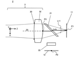
- FIG. 2 is a diagram showing the configuration of the optical system 2 according to the first embodiment.
- the optical system 2 includes a lens group 3 having an optical axis Z0 on which the incident light L10 from the outside is incident, and an optical branching element 21 that branches the incident light L10 from the lens group 3 into visible light L11 and far infrared light L12. And a far-infrared transmission filter 22.
- the direction of the optical axis Z0 of the lens group 3 in the optical system 2 is defined as the Z direction
- the two directions orthogonal to the Z direction are defined as the X and Y directions.
- the object side facing outward from the optical system 2 in the Z direction is defined as the ⁇ Z side or the front
- the opposite image plane side is defined as the + Z side or the rear.
- the optical system 2 has an image formation position P1 formed by visible light L11 and an image formation position P2 formed by far infrared light L12 on the + Z side, that is, behind.
- the imaging surface of the visible imaging sensor 11 is arranged at the imaging position P1 of the visible light L11 by the optical system 2.
- the imaging surface of the far-infrared imaging sensor 12 is arranged at the imaging position P2 of the far-infrared light L12.
- the optical branching element 21 is provided between the lens group 3 and the image pickup sensors 11 and 12.
- the far-infrared transmittance filter 22 is provided between the optical branching element 21 and the far-infrared image pickup sensor 12.
- the optical system 2 of the present embodiment is configured so that, for example, a lens element having a refractive power is not provided between the optical branching element 21 and the image pickup sensors 11 and 12. With this configuration, the size can be reduced from the viewpoint of the total length of the optical system 2 or the number of parts, and the alignment process of the lens after optical branching can be reduced and the cost can be reduced.
- the lens group 3 on the ⁇ Z side (that is, in front of) the optical branching element 21 is included in the incident light L10.
- Each of L11 and far-infrared light L12 constitutes an imaging optical system.
- the imaging positions P1 and P2 are set corresponding to the focal length of the lens group 3.
- the lens group 3 in the optical system 2 is composed of a lens material having light transmission in both the visible region and the far infrared region. Due to the wavelength dependence of the refractive index of the lens material, the focal length of the lens group 3 can vary depending on the wavelength of the light to be imaged.
- the lens group 3 functions as an imaging optical system by applying a refractive power according to the focal length to the incident light L10 from the outside.
- the incident light L10 after passing through the lens group 3 includes visible light L11 and far infrared light L12, and is incident on the optical branching element 21. Visible light L11 and far-infrared light L12 are examples of the first and second lights in the present embodiment, respectively.
- the lens group 3 includes two lens elements 31 and 32 and a diaphragm 30.
- the first lens element 31 and the second lens element 32 are arranged along the optical axis Z0 in order from the front.
- the first lens element 31 is made of calcium halide A (CHA)
- the second lens element 32 is made of zinc sulfide (ZnS) (see FIG. 5).
- FIG. 5 illustrates three types of calcohalide glass having different compositions, which are referred to as calcohalide A, B, and C, respectively.
- the lens material in the lens group 3 is not limited to the above, and various types that transmit the wavelength band of visible light L11 used for visible imaging in the visible region and the wavelength band of far infrared light L12 used for far infrared imaging in the far infrared region. It may be a material.
- the wavelength band transmitted by the lens material may be 0.4 ⁇ m to 12 ⁇ m.
- the diaphragm 30 is, for example, an aperture diaphragm, and limits the amount of visible light L11 and far infrared light L12 in the incident light L10.
- the aperture 30 is arranged between the first and second lens elements 31 and 32 in the first embodiment.
- the diaphragm 30 may be arranged at any position in the lens group 3, and may not necessarily be provided in the optical system 2.
- the optical branching element 21 transmits visible light L11 and emits light to the + Z side in the incident light L10 from the ⁇ Z side, while reflecting far infrared light L12 to the + X side. It is configured to emit light.
- the optical branching element 21 has a specific wavelength band (that is, a transmission band) that selectively transmits light, and is a bandpass filter having optical characteristics that reflects light other than the transmission band, and has a wavelength of visible light L11 in advance. It is configured by setting the band as a transparent band.
- the far-infrared transmission filter 22 is arranged on the + X side of the optical branching element 21 in, for example, the configuration example of FIG. 2, and selectively transmits the far-infrared light L12.
- the far-infrared transmission filter 22 is composed of various filter elements such as a bandpass filter in which the wavelength band of the far-infrared light L12 is set in advance as the transmission band.
- the visible light L11 and the far-infrared light L12 reach the respective imaging positions P1 and P2 behind the lens group 3 via the optical branching element 21 and the like, respectively.
- the lens group 3 as an imaging optical system is optically designed in consideration of the back focus up to.
- FIG. 3 illustrates an optical path of visible light L11 from the rear position P3 of the lens group 3.
- the rear position P3 is a position on the optical axis Z0 on the rearmost lens surface in the lens group 3.
- visible light L11 on the optical axis Z0 in the lens group 3 is emitted from the rear position P3 in the + Z direction and is incident on the optical branching element 21.
- the incident visible light L11 passes through the inside of the optical branching element 21 and is emitted from the optical branching element 21 in the + Z direction to reach the image formation position P1.
- the air-equivalent optical path length that is, the air-equivalent length Lvis of such an optical path corresponds to the focal length Fvis of the visible light L11 by the lens group 3.
- the difference between the air conversion length Lvis and the focal length Fvis is the rear position P3 of the lens group 3. It is represented by the difference in distance between the principal points.
- the shorter the subject distance the farther the image formation position P1 of the visible light L11 is from the focal point of the lens group 3, and the air equivalent length Lvis of the back focus is extended by that amount.
- FIG. 4 illustrates the optical path of the far infrared light L12 from the rear position P3 of the lens group 3.
- the far-infrared light L12 on the optical axis Z0 in the lens group 3 is incident on the optical branching element 21 from the rear position P3 in the same manner as the visible light L11, it is reflected from the optical branching element 21 in the + X direction.
- the reflected far-infrared light L12 passes through the far-infrared transmissive filter 22 and reaches the image formation position P2.
- the air-equivalent length Lir of such an optical path and the focal length Fir of the far-infrared light L12 by the lens group 3 have the same correspondence relationship as in the case of the visible light L11 described above.
- the air equivalent length Lvis of the visible light L11 is shorter than the air equivalent length Lir of the far infrared light L12 for each back focus optical path as shown in FIGS.
- the lens group 3 is configured.
- the lens group 3 is configured so as to satisfy the following conditional expression (1). 0.13 ⁇ (Lir-Lvis) /Fir ⁇ 0.23 ... (1)
- the middle side (Lir-Lvis) / Fir in the above equation (1) may be referred to as a factor Lf.
- FIG. 5 is a diagram illustrating data of various lens materials.
- various lens materials applicable to the optical system 2
- the names and compositions of each, the refractive indexes nvis and nir of each wavelength ⁇ vis and ⁇ ir, and the ratio Nr described later are shown.
- the refractive index nvis of the visible light L11 and the refractive index ir of the far-infrared light L12 have various values in various lens materials, respectively.
- the above equation (1) utilizes the universal characteristics commonly found in various wavelength-dependent lens materials as shown in the following findings, and is not limited to the lens material and the number of lenses. It can be applied to various optical systems.
- focal lengths Fvis and Fir can be approximated by the following equation (12) based on the lens manufacturer's formula when the lens group 3 is regarded as a thin-walled lens.
- C is a constant defined by the curvature of the lens. Fvis ⁇ C / (nvis-1) Fire ⁇ C / (nir-1) ... (12)
- the factor Lf of the conditional equation (1) is of the following equation (13) using the respective refractive indexes nvis and nir for the visible light L11 and the far infrared light L12. Can be approximated as follows. Lf ⁇ (nvis-1) / (nir-1) -1 ... (13)
- the minimum value on the right side of the above equation (13) in FIG. 5 is "0.139" according to the calcohalide CHA.
- the above equation (13) uses an approximation that regards the optical system 2 as a thin-walled lens.
- the left side of the above equation (13) in the actual optical system 2 tends to be larger than the ideal case (that is, the right side of the above equation (13)) as in the above approximation.
- the numerical range of the above equation (1) was found in consideration of practical variations due to various differences in the optical system such as the lens material and the number of lenses.
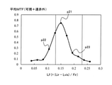
- FIG. 6 is a graph showing a simulation result of the imaging performance of the optical system 2 in the first embodiment.
- the vertical axis is the evaluation value of the average MTF (modulation transfer function).
- the average MTF is an average value of the MTF of the visible light L11 and the MTF of the far infrared light L12 as described later.
- the factor Lf of the above equation (1) was set to various values, and the optical design was optimized for each set value.
- software CODE-V manufactured by Synopsys was used.
- the average MTF was used from the viewpoint of evaluating both the imaging performance of the visible light L11 and the imaging performance of the far infrared light L12 in the designed optical system 2.
- the setting of the factor Lf was changed by an optical design in which the focal length Fir of the far-infrared light L12 and the air-equivalent length Lir were fixed, while the air-equivalent length Lvis of the visible light L11 was changed.
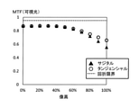
- FIGS. 7 and 8 The MTF of visible light L11 and the MTF of far-infrared light L12 in the average MTF of Example 1 are illustrated in FIGS. 7 and 8, respectively.
- the horizontal axis shows the image height as a percentage
- the vertical axis shows the calculated value of each MTF.
- the MTF curve in the sagittal direction, the MTF curve in the tangential direction, and the boundary line of the diffraction limit are illustrated.
- the wavelength ⁇ vis of the above-mentioned d-line and the high-frequency spatial frequency of 30 lp / mm were used (lp: line pairs).
- the wavelength ⁇ ir described above and the low frequency spatial frequency of 10 lp / mm were used.
- the pixel pitch of each of the image pickup sensors 11 and 12 was taken into consideration.
- the spatial frequency of the far-infrared MTF is set to be lower than the spatial frequency of the visible MTF. I set it.
- the average image heights of 0%, 30%, 60%, and 100% in the sagittal direction and the tangential direction in the MTF of visible light L11 and the MTF of far infrared light L12 obtained as shown in FIGS. 7 and 8, respectively.
- the average MTF was calculated by calculation. It is considered that the larger the average MTF is, the higher the imaging performance of the visible light L11 and the far infrared light L12 is.
- the graph of FIG. 6 it has a mountain-shaped raised graph shape in a numerical range such as the following equation (1a) including the numerical range of the conditional expression (1). 0.08 ⁇ (Lir-Lvis) /Fir ⁇ 0.28 ... (1a) Within the range of the above equation (1a), the average MTF in the optical system 2 of Example 1 satisfying the conditional equation (1) is significantly larger than the average MTF of Examples 2 and 3 not satisfying the conditional equation (1). .. As described above, it was confirmed that the conditional expression (1) can improve the imaging performance of the visible light L11 and the far infrared light L12.
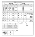
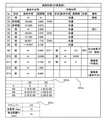
- FIG. 9 is a chart showing a numerical example 1 of the optical system 2 of the first embodiment.
- the chart of FIG. 9 includes surface data D11a of the optical system 2 of the first embodiment in the present embodiment, aspherical surface data D11b, and various data D11c.
- the surface data D11a indicates the shape, radius of curvature, surface spacing, and material of each surface S1 to S11 arranged in order in the optical system 2 from the object side, and is provided with a remarks column.
- the surface number S2 is a lens surface on the object side of the first lens element 31, and has an aspherical shape.
- the surface number S1 represents an object such as a subject 10 located at infinity (see the remarks column).
- the surface number S7 is the surface on the object side of the optical branching element 21, and after this surface, the surface through which the optical path of the visible light L11 and the optical path of the far infrared light L12 pass. And are shown respectively (see FIGS. 3 and 4).
- the aspherical surface data D11b shows various coefficients of the following equation (2) that define the aspherical surface shape for each surface S2 and S3 of the aspherical surface shape in the surface data D11a.
- h is the height in the radial direction
- k is the cornic constant
- An is the nth-order aspherical coefficient.
- n is an even number of 4 or more and 20 or less, and the sum of each n is taken.
- the sag amount z at the radial height h on the target surface is defined to be rotationally symmetric.
- the factor Lf and the average MTF of the conditional expression (1) are obtained as shown at the plot point p11 in FIG.
- FIG. 10 is a chart showing a numerical example 2 of the optical system 2 of the first embodiment.
- the chart of FIG. 10 includes the surface data D12a of the optical system 2 of the second embodiment in the present embodiment, the aspherical surface data D12b, and various data D12c.
- the data D12a to D12c show the same information as the data D11a to D11c of the first embodiment for the optical system 2 of the second embodiment of the present embodiment.
- the surface spacing of the surface data D12a with respect to the surface number S8 is changed from FIG. 9 in order to extend the air conversion length Lvis of the visible light L11 as compared with the first embodiment.
- the optical design such as the surface shape was optimized.
- the factor Lf and the average MTF shown at the plot point p12 in FIG. 6 are obtained.
- FIG. 11 is a chart showing a numerical example 3 of the optical system 2 of the first embodiment.
- the chart of FIG. 11 includes the surface data D13a of the optical system 2 of the third embodiment in the present embodiment, the aspherical surface data D13b, and various data D13c.
- the data D13a to D13c show the same information as the data D11a to D11c of the first embodiment for the optical system 2 of the third embodiment of the present embodiment.
- Example 3 of this embodiment contrary to Example 2, the air conversion length Lvis of visible light L11 was shortened as compared with Example 1 to optimize the optical design.
- the factor Lf and the average MTF shown at the plot point p13 in FIG. 6 are obtained.
- the factor Lf is not only at the plot points p11 of Example 1 but also at the plot points p12 and p13 of Examples 2 and 3.
- the imaging performance of both with the external light L12 can be improved.
- the optical system 2 in the present embodiment is connected to the image formation position P1 which is an example of the first image formation position by the visible light L11 as an example of the first light having a wavelength in the visible region. Image.
- the optical system 2 is formed by the far-infrared light L12 as an example of the second light having a wavelength in the far-infrared region at the image formation position P2 which is an example of the second image formation position.
- the optical system 2 includes a lens group 3 and an optical branching element 2.
- the lens group 3 has an optical axis Z0 extending rearward from the front where the visible light L11 and the far infrared light L12 are incident, a focal length Fvis of the visible light L11, and a focal length Fir of the far infrared light L12. Have.
- the optical branching element 21 is arranged behind the lens group 3, and branches the visible light L11 and the far-infrared light L12 from the lens group 3 to each other to guide the visible light L11 to the image formation position P1 and far-infrared.
- the external light L12 is guided to the image formation position P2.
- the lens group 3 is visible so that the image formation position P1 corresponds to the focal length Fvis of the visible light L11 and the image formation position P2 corresponds to the focal length Fir of the far infrared light L12 separately from the image formation position P1. It is composed of lens elements 31 and 32 that transmit light L11 and far-infrared light L12.
- the image formation position P1 of the visible light L11 and the image formation position P of the far infrared light L12 are set corresponding to the focal lengths Fvis and Fir of the lens group 3, respectively, and optical branching is performed.
- the lens group 3 in front of the element 2 constitutes both imaging optical systems. This makes it possible to simplify the configuration of the back focus behind the optical branching element 2 in the optical system 2, and to facilitate both visible imaging and far-infrared imaging, such as downsizing of the imaging device 2.
- the air conversion length Lvis which is an example of the first air conversion length through which the visible light L11 passes from the rear end position in the lens group 3, that is, the rear position P3 to the imaging position P1
- the infrared light L12 is shorter than the air equivalent length Lir, which is an example of the second air equivalent length that passes from the rear position P3 to the image formation position P2.
- the optical system 2 in the present embodiment is a conditional expression based on the air equivalent length Lvis of the visible light L11 in the back focus, the air equivalent length Lir of the far infrared light L12, and the focal length Fir of the far infrared light L12. (1) may be satisfied. This makes it possible to optimize the back focus in the optical system 2 and improve both the imaging performance of the visible light L11 and the imaging performance of the far-infrared light L12. Further, the optical system 2 in the present embodiment may satisfy the numerical range of the above equation (1a) instead of the conditional equation (1).
- the lens element is not provided behind the optical branching element 2, and the lens elements 31 and 32 of the lens group 3 are provided in front of the optical branching element 2.
- the optical system 2 can be miniaturized.
- the first lens element 31 in the lens group 3 is made of calcohalide glass.
- the optical system 2 having light transmission in the visible region and the far infrared region can be provided with a material that is easy to handle in various applications.
- the lens element of the calcohalide material is not particularly limited to the first lens element 31. Further, the first lens element 31 may be made of a lens material other than the calcohalide material.
- the optical branching element 21 has an optical characteristic of transmitting visible light L11 and reflecting far infrared light L12.
- the optical path of the far-infrared light L12 which may be longer than the optical path of the visible light L11, is bent (see FIGS. 3 and 4), and the optical system 2 can be easily miniaturized. Can be done.
- the image pickup apparatus 1 includes an optical system 2, a visible image pickup sensor 11 which is an example of a first image pickup unit, and a far infrared image pickup sensor 12 which is an example of a second image pickup unit.
- the visible image pickup sensor 11 is arranged at the image formation position P1 of the visible light L11 by the optical system 2 and captures an image by the visible light L11.
- the far-infrared imaging sensor 12 is arranged at the imaging position P2 of the far-infrared light L12 by the optical system 2 and acquires an image by the far-infrared light L12.
- the optical system 2 can reduce the size of the configuration for achieving both visible imaging and far-infrared imaging, and improve the imaging performance of both, making it easy to achieve both. can.
- the image pickup system 20 includes an image pickup device 1 and a control unit 15 that analyzes various images Im1 and Im2 captured by the image pickup device 1.
- the optical system 2 of the image pickup apparatus 1 makes it easy to perform both the analysis of the visible image Im1 and the analysis of the far-infrared image Im2.
- optical system according to the present embodiment will be described by omitting the description of the same configuration and operation as the optical system 2 and the image pickup apparatus 1 according to the first embodiment as appropriate.
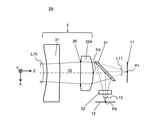
- FIG. 12 shows the configuration of the optical system 2A according to the second embodiment.
- zinc sulfide is exemplified as the lens material of the second lens element 32.
- the lens material of the second lens element 32A is made of the same calcium halide glass as the first lens element 31.
- the lens group 3A can be formed of glass having high productivity and workability, and it is easy to use in various applications.
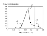
- FIG. 13 shows a graph of the simulation result of the imaging performance of the optical system 2A of the present embodiment.
- the optical design of the optical system 2A of the second embodiment was optimized by setting the factor Lf to various values as in the case of FIG. 6 of the first embodiment.
- Examples 1, 2, and 3 of the second embodiment correspond to plot points p21, p22, and p23 in the graph of FIG. 13, respectively.
- FIG. 14 shows the numerical embodiment 1 of the optical system 2A of the second embodiment in the same manner as the first embodiment.
- the surface data D21a, the aspherical surface data D21b, and the various data D21c in FIG. 14 provide information about the optical system 2A of the first embodiment in the present embodiment with the data D11a to D11c in FIG. It is shown in the same manner.
- the optical system 2A of this embodiment has a factor Lf satisfying the conditional expression (1) as shown in the plot point p21 of FIG.
- FIG. 15 shows the numerical embodiment 2 of the optical system 2A of the second embodiment in the same manner as the above embodiment.
- the surface data D22a, the aspherical surface data D22b, and the various data D22c in FIG. 15 show information about the optical system 2A of the second embodiment in the present embodiment, respectively.
- the optical system 2A of this embodiment has a factor Lf that is lower than the lower limit of the conditional expression (1).
- FIG. 16 shows the numerical embodiment 3 of the optical system 2A of the second embodiment in the same manner as the above embodiment.
- the data D23a, D23b, and D23c in FIG. 16 indicate information about the optical system 2A of the third embodiment in the present embodiment, respectively.
- the optical system 2A of this example has a factor Lf that exceeds that of Example 1 as shown in the plot point p23 of FIG.
- the average MTF between the visible light L11 and the far-infrared light L12 in the optical systems 2A of the first to third embodiments of the present embodiment has a range in which the factor Lf is defined by the conditional equation (1). It is especially high within. Similar to the first embodiment, the optical system 2A of the present embodiment can also improve the imaging performance of both the visible light L11 and the far infrared light L12 in a compact configuration.
- FIG. 17 shows the configuration of the optical system 2B according to the third embodiment.
- the optical system 2B according to the present embodiment further includes a third lens element 33 arranged behind the second lens element 32 in the lens group 3 in addition to the same configuration as the optical system 2 of the first embodiment.
- the third lens element 33 is made of a lens material that transmits visible light L11 and far infrared light L12, such as calcium halide CHA.
- numerical simulations of various examples were performed in the same manner as in the first and second embodiments.
- FIG. 18 shows a graph of the simulation result of the imaging performance of the optical system 2B of the present embodiment.
- FIG. 19 shows the numerical embodiment 1 of the optical system 2B of the third embodiment in the same manner as in each of the above embodiments.
- the surface data D31a, the aspherical surface data D31b, and the various data D31c in FIG. 19 show information about the optical system 2B of the first embodiment in the present embodiment, respectively.
- the average MTF in the optical systems 2B of the first to third embodiments of the present embodiment also has a particularly high factor Lf within the range of the conditional expression (1).
- the optical system 2B of the present embodiment can also improve the imaging performance of both the visible light L11 and the far infrared light L12, as in each of the above embodiments.
- FIG. 22 shows the configuration of the optical system 2C according to the fourth embodiment.
- the optical system 2C according to the present embodiment further includes a fourth lens element 34 arranged behind the first lens element 31 in the lens group 3 in addition to the same configuration as the optical system 2B of the third embodiment.
- the fourth lens element 34 is made of a lens material that transmits visible light L11 and far infrared light L12.
- numerical simulations of various examples were performed in the same manner as in the first to third embodiments.
- FIG. 23 shows a graph of the simulation result of the imaging performance of the optical system 2C of the present embodiment.
- the factors Lf 0.196 mm, 0.096 mm and 0.255 mm were set, respectively.
- FIGS. 24 to 26 show numerical examples 1 to 3 of the optical system 2C of the fourth embodiment in the same manner as in each of the above embodiments.
- the data D41a to D41c, D42a to D42c, and D43a to D43c in FIGS. 24, 25, and 26 show information about the optical system 2C of Examples 1, 2, and 3, respectively, in the present embodiment.
- the average MTF in the optical systems 2C of the first to third embodiments of the present embodiment also has a particularly high factor Lf within the range of the conditional expression (1).
- the optical system 2C of the present embodiment can also improve the imaging performance of both the visible light L11 and the far-infrared light L12, as in each of the above-described embodiments.
- the graph shape is flattened within the range of the conditional expression (1) as compared with FIG. 6 and the like. According to this embodiment, the number of lenses can be increased to facilitate improvement in imaging performance.
- the number of lenses in the lens group 3 of the optical system 2C is 4 or less has been described, but the number of lenses may be 5 or more. Even in this case, the imaging performance can be improved as in each of the above embodiments.
- Embodiments 1 to 4 have been described as examples of the techniques disclosed in the present application.
- the technique in the present disclosure is not limited to this, and can be applied to embodiments in which changes, substitutions, additions, omissions, etc. are made as appropriate. It is also possible to combine the components described in each of the above embodiments into a new embodiment. Therefore, other embodiments will be exemplified below.
- the optical systems 2, 2A to 2C in which the optical branching element 21 passes through the visible light L11 and reflects the far infrared light L12 are exemplified, but the present disclosure is not limited to this. An example of modification of this point will be described with reference to FIG. 27.
- FIG. 27 illustrates the configuration of the optical system 2D of the modified example of the first embodiment.
- the optical branching element 23 that reflects visible light L11 and transmits far infrared light L12 is provided. Be prepared.
- the optical branching element 23 of this modification is composed of a bandpass filter in which the wavelength band of the far infrared light L12 is set in advance as the transmission band.
- the far-infrared transmission filter 22 is arranged on the + Z side of, for example, the optical branching element 23.
- the optical system 2D of this modification in the incident light L10 emitted from the lens group 3 in the + Z direction, the visible light L11 is reflected by the optical branching element 23 and emitted in the + X direction, while the far infrared light L12 is optical branched. It passes through the element 23 and emits light in the + Z direction.
- the above-mentioned conditional expression (1) may be satisfied by the air conversion length Lvis of the optical path of the visible light L11 and the air conversion length Lir of the optical path of the far infrared light L12.
- the optical system 2D of the present modification can easily realize the image pickup apparatus 1 that achieves both visible imaging and far-infrared imaging.
- the optical branching elements 21 and 23 are configured by a bandpass filter.
- the optical branching elements 21 and 23 are not limited to the bandpass filter, and may be configured by various band splitters, for example, a highpass filter or a lowpass filter.
- the far-infrared transmittance filter 22 may be provided integrally with the far-infrared imaging sensor 12 or the optical branching element 21.
- the far-infrared transmission filter 22 may be omitted from the optical systems 2, 2A to 2D.
- an optical element other than the far-infrared transmission filter 22 is not arranged between the optical branching elements 21 and 23 and the imaging positions P1 and P2 .
- various optical elements may be arranged between the optical branching elements 21 and 23 and the imaging positions P1 and P2, for example, various wavelength filters, polarization filters, polarizing plates, mirrors and the like. It may be arranged.
- the optical systems 2, 2A to 2D including the aspherical lens surface are exemplified.
- the optical system of the present embodiment does not have to include an aspherical lens surface, and for example, all the lens elements included in the lens group 3 may be spherical lenses. Further, the optical system of the present embodiment may include a lens element having a free curved surface that is not rotationally symmetric in the lens group 3.
- the present disclosure is applicable to various applications that combine visible imaging and far-infrared imaging.
Landscapes
- Physics & Mathematics (AREA)
- Engineering & Computer Science (AREA)
- Multimedia (AREA)
- Signal Processing (AREA)
- General Physics & Mathematics (AREA)
- Optics & Photonics (AREA)
- Spectroscopy & Molecular Physics (AREA)
- Health & Medical Sciences (AREA)
- Toxicology (AREA)
- Human Computer Interaction (AREA)
- Lenses (AREA)
- Studio Devices (AREA)
Priority Applications (2)
| Application Number | Priority Date | Filing Date | Title |
|---|---|---|---|
| JP2022545291A JP7739301B2 (ja) | 2020-08-24 | 2021-03-15 | 光学系および撮像装置、撮像システム |
| US18/102,879 US12375782B2 (en) | 2020-08-24 | 2023-01-30 | Optical system, imaging device, and imaging system |
Applications Claiming Priority (2)
| Application Number | Priority Date | Filing Date | Title |
|---|---|---|---|
| JP2020140727 | 2020-08-24 | ||
| JP2020-140727 | 2020-08-24 |
Related Child Applications (1)
| Application Number | Title | Priority Date | Filing Date |
|---|---|---|---|
| US18/102,879 Continuation US12375782B2 (en) | 2020-08-24 | 2023-01-30 | Optical system, imaging device, and imaging system |
Publications (1)
| Publication Number | Publication Date |
|---|---|
| WO2022044398A1 true WO2022044398A1 (ja) | 2022-03-03 |
Family
ID=80355059
Family Applications (1)
| Application Number | Title | Priority Date | Filing Date |
|---|---|---|---|
| PCT/JP2021/010288 Ceased WO2022044398A1 (ja) | 2020-08-24 | 2021-03-15 | 光学系および撮像装置、撮像システム |
Country Status (3)
| Country | Link |
|---|---|
| US (1) | US12375782B2 (https=) |
| JP (1) | JP7739301B2 (https=) |
| WO (1) | WO2022044398A1 (https=) |
Citations (5)
| Publication number | Priority date | Publication date | Assignee | Title |
|---|---|---|---|---|
| JPS5969711A (ja) * | 1982-09-20 | 1984-04-20 | ロツキ−ド・ミサイルズ・アンド・スペ−ス・コンパニ−・インコ−ポレ−テツド | 光学系及び光学系を設計するための光学材料の選定方法 |
| JP2014185917A (ja) * | 2013-03-22 | 2014-10-02 | Nikon Corp | 撮像装置 |
| CN108761733A (zh) * | 2018-07-03 | 2018-11-06 | 中山联合光电科技股份有限公司 | 大光圈、高像素、高低温共焦、双光路的光学系统 |
| CN109407273A (zh) * | 2018-11-14 | 2019-03-01 | 中国航空工业集团公司洛阳电光设备研究所 | 一种可见光、中波红外和长波红外共光路光学系统 |
| WO2020071071A1 (ja) * | 2018-10-02 | 2020-04-09 | パナソニック株式会社 | 光学素子およびその製造方法 |
Family Cites Families (6)
| Publication number | Priority date | Publication date | Assignee | Title |
|---|---|---|---|---|
| US4087689A (en) * | 1976-11-22 | 1978-05-02 | Hughes Aircraft Company | Boresighting system for infrared optical receiver and transmitter |
| US4702569A (en) | 1982-09-20 | 1987-10-27 | Lockheed Missiles & Space Company, Inc. | Color-corrected Petzval lens systems |
| JP2006235139A (ja) | 2005-02-24 | 2006-09-07 | Mitsubishi Electric Corp | 2波長結像光学系 |
| JP2006324810A (ja) | 2005-05-17 | 2006-11-30 | Fujifilm Holdings Corp | 光学モジュール |
| KR20110037448A (ko) | 2009-10-07 | 2011-04-13 | (주)토핀스 | 열화상카메라용 일축형 렌즈모듈 |
| JP2017163297A (ja) | 2016-03-09 | 2017-09-14 | キヤノン株式会社 | 撮像装置 |
-
2021
- 2021-03-15 WO PCT/JP2021/010288 patent/WO2022044398A1/ja not_active Ceased
- 2021-03-15 JP JP2022545291A patent/JP7739301B2/ja active Active
-
2023
- 2023-01-30 US US18/102,879 patent/US12375782B2/en active Active
Patent Citations (5)
| Publication number | Priority date | Publication date | Assignee | Title |
|---|---|---|---|---|
| JPS5969711A (ja) * | 1982-09-20 | 1984-04-20 | ロツキ−ド・ミサイルズ・アンド・スペ−ス・コンパニ−・インコ−ポレ−テツド | 光学系及び光学系を設計するための光学材料の選定方法 |
| JP2014185917A (ja) * | 2013-03-22 | 2014-10-02 | Nikon Corp | 撮像装置 |
| CN108761733A (zh) * | 2018-07-03 | 2018-11-06 | 中山联合光电科技股份有限公司 | 大光圈、高像素、高低温共焦、双光路的光学系统 |
| WO2020071071A1 (ja) * | 2018-10-02 | 2020-04-09 | パナソニック株式会社 | 光学素子およびその製造方法 |
| CN109407273A (zh) * | 2018-11-14 | 2019-03-01 | 中国航空工业集团公司洛阳电光设备研究所 | 一种可见光、中波红外和长波红外共光路光学系统 |
Also Published As
| Publication number | Publication date |
|---|---|
| US12375782B2 (en) | 2025-07-29 |
| JPWO2022044398A1 (https=) | 2022-03-03 |
| JP7739301B2 (ja) | 2025-09-16 |
| US20230179842A1 (en) | 2023-06-08 |
Similar Documents
| Publication | Publication Date | Title |
|---|---|---|
| JP6615974B2 (ja) | ズームレンズシステムおよび撮像装置 | |
| CN103608714B (zh) | 光学单元及内窥镜 | |
| JP6688073B2 (ja) | 光学システムおよび光学システムを有する装置 | |
| WO2015025516A1 (ja) | 撮像レンズ系及びこれを備えた撮像装置 | |
| KR20140024647A (ko) | 반사형 망원 렌즈 및 이를 포함한 촬영 장치 | |
| JP7194979B2 (ja) | 撮像光学系及び撮像装置 | |
| WO2009098864A1 (ja) | 測距装置及び測距方法 | |
| CN106772959A (zh) | 一种短波、长波红外双波段共焦面大相对孔径光学系统 | |
| JP2012088705A (ja) | ズームレンズシステム | |
| CN111965802A (zh) | 一种长后工作距光学无热化长波红外镜头 | |
| TW202242471A (zh) | 光學鏡片系統及飛時測距感測模組 | |
| CN111522186A (zh) | 镜头 | |
| CN112987242A (zh) | 光学成像系统、取像装置及电子设备 | |
| CN109068956B (zh) | 物镜光学系统以及具备物镜光学系统的内窥镜装置 | |
| CN206282023U (zh) | 一种短波、长波红外双波段共焦面大相对孔径光学系统 | |
| JP7739301B2 (ja) | 光学系および撮像装置、撮像システム | |
| US20150146284A1 (en) | Lens for infrared cameras | |
| JP2021096283A (ja) | レンズ系 | |
| CN102043246B (zh) | 一种中红外成像系统 | |
| RU2621366C1 (ru) | Компактный объектив среднего ик диапазона | |
| JP2021021776A (ja) | 撮像レンズおよび撮像装置 | |
| GB2531726A (en) | Compact multispectral wide angle refractive optical system | |
| CN111381352A (zh) | 透射式双谱段共孔径变焦光学系统 | |
| CN212569267U (zh) | 一种长后工作距光学无热化长波红外镜头 | |
| JP2024116428A (ja) | 光学系、撮像装置および撮像システム |
Legal Events
| Date | Code | Title | Description |
|---|---|---|---|
| 121 | Ep: the epo has been informed by wipo that ep was designated in this application |
Ref document number: 21860830 Country of ref document: EP Kind code of ref document: A1 |
|
| ENP | Entry into the national phase |
Ref document number: 2022545291 Country of ref document: JP Kind code of ref document: A |
|
| NENP | Non-entry into the national phase |
Ref country code: DE |
|
| 122 | Ep: pct application non-entry in european phase |
Ref document number: 21860830 Country of ref document: EP Kind code of ref document: A1 |