WO2022044398A1 - Optical system, imaging device, and imaging system - Google Patents
Optical system, imaging device, and imaging system Download PDFInfo
- Publication number
- WO2022044398A1 WO2022044398A1 PCT/JP2021/010288 JP2021010288W WO2022044398A1 WO 2022044398 A1 WO2022044398 A1 WO 2022044398A1 JP 2021010288 W JP2021010288 W JP 2021010288W WO 2022044398 A1 WO2022044398 A1 WO 2022044398A1
- Authority
- WO
- WIPO (PCT)
- Prior art keywords
- light
- optical system
- image
- optical
- lens group
- Prior art date
Links
- 230000003287 optical effect Effects 0.000 title claims abstract description 276
- 238000003384 imaging method Methods 0.000 title claims description 74
- 230000015572 biosynthetic process Effects 0.000 claims abstract description 41
- 239000011521 glass Substances 0.000 claims description 4
- 239000000463 material Substances 0.000 description 28
- 238000003331 infrared imaging Methods 0.000 description 17
- 238000004088 simulation Methods 0.000 description 14
- 230000005540 biological transmission Effects 0.000 description 13
- 238000006243 chemical reaction Methods 0.000 description 9
- 230000004048 modification Effects 0.000 description 8
- 238000012986 modification Methods 0.000 description 8
- 238000013461 design Methods 0.000 description 6
- 230000006870 function Effects 0.000 description 4
- 238000000034 method Methods 0.000 description 4
- 239000005083 Zinc sulfide Substances 0.000 description 3
- 238000004458 analytical method Methods 0.000 description 3
- 229910052791 calcium Inorganic materials 0.000 description 3
- 239000011575 calcium Substances 0.000 description 3
- 238000010586 diagram Methods 0.000 description 3
- 229910052984 zinc sulfide Inorganic materials 0.000 description 3
- 238000007792 addition Methods 0.000 description 2
- -1 calcium halide Chemical class 0.000 description 2
- 238000005516 engineering process Methods 0.000 description 2
- 238000011156 evaluation Methods 0.000 description 2
- 239000000203 mixture Substances 0.000 description 2
- 230000035945 sensitivity Effects 0.000 description 2
- 238000006467 substitution reaction Methods 0.000 description 2
- 238000002834 transmittance Methods 0.000 description 2
- DRDVZXDWVBGGMH-UHFFFAOYSA-N zinc;sulfide Chemical compound [S-2].[Zn+2] DRDVZXDWVBGGMH-UHFFFAOYSA-N 0.000 description 2
- OYPRJOBELJOOCE-UHFFFAOYSA-N Calcium Chemical compound [Ca] OYPRJOBELJOOCE-UHFFFAOYSA-N 0.000 description 1
- 229910021417 amorphous silicon Inorganic materials 0.000 description 1
- 238000004364 calculation method Methods 0.000 description 1
- 230000008859 change Effects 0.000 description 1
- 230000001419 dependent effect Effects 0.000 description 1
- 230000000694 effects Effects 0.000 description 1
- 230000004907 flux Effects 0.000 description 1
- 239000005283 halide glass Substances 0.000 description 1
- 238000010191 image analysis Methods 0.000 description 1
- 230000006872 improvement Effects 0.000 description 1
- 230000004297 night vision Effects 0.000 description 1
- 238000005457 optimization Methods 0.000 description 1
- 230000010287 polarization Effects 0.000 description 1
- 230000008569 process Effects 0.000 description 1
- 239000000126 substance Substances 0.000 description 1
- 238000001931 thermography Methods 0.000 description 1
- 238000012546 transfer Methods 0.000 description 1
Images


Classifications
-
- H—ELECTRICITY
- H04—ELECTRIC COMMUNICATION TECHNIQUE
- H04N—PICTORIAL COMMUNICATION, e.g. TELEVISION
- H04N23/00—Cameras or camera modules comprising electronic image sensors; Control thereof
- H04N23/10—Cameras or camera modules comprising electronic image sensors; Control thereof for generating image signals from different wavelengths
- H04N23/13—Cameras or camera modules comprising electronic image sensors; Control thereof for generating image signals from different wavelengths with multiple sensors
- H04N23/16—Optical arrangements associated therewith, e.g. for beam-splitting or for colour correction
-
- G—PHYSICS
- G02—OPTICS
- G02B—OPTICAL ELEMENTS, SYSTEMS OR APPARATUS
- G02B13/00—Optical objectives specially designed for the purposes specified below
- G02B13/14—Optical objectives specially designed for the purposes specified below for use with infrared or ultraviolet radiation
-
- G—PHYSICS
- G02—OPTICS
- G02B—OPTICAL ELEMENTS, SYSTEMS OR APPARATUS
- G02B27/00—Optical systems or apparatus not provided for by any of the groups G02B1/00 - G02B26/00, G02B30/00
- G02B27/10—Beam splitting or combining systems
- G02B27/1006—Beam splitting or combining systems for splitting or combining different wavelengths
- G02B27/1013—Beam splitting or combining systems for splitting or combining different wavelengths for colour or multispectral image sensors, e.g. splitting an image into monochromatic image components on respective sensors
-
- H—ELECTRICITY
- H04—ELECTRIC COMMUNICATION TECHNIQUE
- H04N—PICTORIAL COMMUNICATION, e.g. TELEVISION
- H04N23/00—Cameras or camera modules comprising electronic image sensors; Control thereof
- H04N23/10—Cameras or camera modules comprising electronic image sensors; Control thereof for generating image signals from different wavelengths
- H04N23/11—Cameras or camera modules comprising electronic image sensors; Control thereof for generating image signals from different wavelengths for generating image signals from visible and infrared light wavelengths
-
- H—ELECTRICITY
- H04—ELECTRIC COMMUNICATION TECHNIQUE
- H04N—PICTORIAL COMMUNICATION, e.g. TELEVISION
- H04N23/00—Cameras or camera modules comprising electronic image sensors; Control thereof
- H04N23/45—Cameras or camera modules comprising electronic image sensors; Control thereof for generating image signals from two or more image sensors being of different type or operating in different modes, e.g. with a CMOS sensor for moving images in combination with a charge-coupled device [CCD] for still images
-
- H—ELECTRICITY
- H04—ELECTRIC COMMUNICATION TECHNIQUE
- H04N—PICTORIAL COMMUNICATION, e.g. TELEVISION
- H04N23/00—Cameras or camera modules comprising electronic image sensors; Control thereof
- H04N23/50—Constructional details
- H04N23/55—Optical parts specially adapted for electronic image sensors; Mounting thereof
Definitions
- the present disclosure relates to an optical system, an imaging device, and an imaging system that perform imaging in the visible region and imaging in the far infrared region.
- Patent Document 1 discloses a uniaxial lens module for a thermal image camera, which aims to acquire a vivid image by simultaneously capturing visible light and a far-infrared band with the thermal image camera.
- the lens module is located behind the objective lens facing the subject, the light beam separator that reflects far infrared rays from the light that passes through the objective lens and transmits visible light, and the light beam separator.
- It includes a visible light imaging lens located on the side and a far infrared imaging lens.
- the visible light imaging lens forms an image on the CCD sensor located on the rear side with visible light from the luminous flux separator.
- the far-infrared imaging lens forms an image with far-infrared rays from a light beam separator on a far-infrared detector that converts an optical image into a thermal image signal and outputs it.
- the present disclosure provides an optical system, an imaging device, and an imaging system that can facilitate both imaging in the visible region and imaging in the far infrared region.
- the optical system in the present disclosure is imaged at a first imaging position by a first light having a wavelength in the visible region and at a second imaging position by a second light having a wavelength in the far infrared region. It is an optical system.
- the optical system includes a lens group and an optical branching element.
- the lens group has an optical axis extending rearward from the front where the first and second lights are incident, a focal length of the first light, and a focal length of the second light.
- the optical branching element is arranged behind the lens group and branches the first and second lights from the lens group to each other to guide the first light to the first imaging position and the second light. Is guided to the second image formation position.
- the first image formation position corresponds to the focal length of the first light
- the second image formation position corresponds to the focal length of the second light separately from the first image formation position.
- the image pickup apparatus in the present disclosure includes the above optical system, a first image pickup unit, and a second image pickup unit.
- the first image pickup unit is arranged at the first image formation position and captures an image by the first light.
- the second image pickup unit is arranged at the second image formation position and captures an image by the second light.
- the image pickup system in the present disclosure includes the above image pickup device and a control unit that analyzes an image captured by the image pickup device.
- optical system and the image pickup apparatus of the present disclosure it is possible to facilitate both the image pickup in the visible region and the image pickup in the far infrared region.
- the figure for demonstrating the image pickup apparatus and the image pickup system which concerns on Embodiment 1 of this disclosure The figure which shows the structure of the optical system which concerns on Embodiment 1.
- Graph showing the simulation result of the imaging performance of the optical system of the first embodiment A graph illustrating an MTF of visible light in the optical system of the first embodiment.
- Numerical value of the optical system of the first embodiment Chart showing the first embodiment Numerical value of the optical system of the first embodiment A chart showing the second embodiment.
- Numerical value of the optical system of the first embodiment A chart showing the third embodiment.
- Graph showing the simulation result of the imaging performance of the optical system of the second embodiment Numerical value of the optical system of the second embodiment A chart showing the first embodiment.
- Numerical value of the optical system of the second embodiment A chart showing the second embodiment. Numerical value of the optical system of the second embodiment A chart showing the third embodiment.
- Embodiment 1 of the present disclosure will be described with reference to the drawings.
- an image pickup device that achieves both image pickup in the visible region and image pickup in the far infrared region and an optical system thereof will be described.
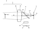
- FIG. 1 is a diagram for explaining the image pickup device 1 and the image pickup system 20 according to the present embodiment.
- the image pickup system 20 of the present embodiment includes an image pickup device 1 and a control unit 15.
- the image pickup apparatus 1 includes an optical system 2, a visible image pickup sensor 11, and a far infrared image pickup sensor 12, as shown in FIG. 1, for example.
- the image pickup apparatus 1 of the present embodiment is a camera device that coaxially performs an image pickup in a visible region, that is, a visible image pickup, and an image pickup in a far infrared region, that is, a far infrared image pickup, by an optical system 2.
- the visible region has a wavelength of 400 nm to 750 nm
- the far infrared region has a wavelength of 3 ⁇ m to 20 ⁇ m.
- a part of the visible region and a part of the far-infrared region are the targets of the visible imaging and the far-infrared imaging by the image pickup apparatus 1.
- the far infrared region may be 7 ⁇ m to 12 ⁇ m.
- the image pickup apparatus 1 of the present embodiment can be applied to various applications such as a combination of thermal imaging using far-infrared imaging, a motion sensor or night vision, and visible imaging.
- image analysis such as measuring the temperature of a subject 10 such as a person and performing individual recognition on the same subject 10 can be applied.
- the image pickup device 1 of this system 20 can be considered as various application examples such as being incorporated in various electronic devices such as mobile terminals, being mounted on a moving body such as a drone or a vehicle, or being installed like a surveillance camera or the like. Be done. In these various application examples, it is useful to reduce the size of the image pickup apparatus 1.
- the optical system 2 collects the light L10 incident from the subject 10 and guides the visible light L11 in the incident light L10 to the visible image pickup sensor 11 and far-infrared light in the incident light L10.
- the external light L12 is guided to the far infrared imaging sensor 12.
- the optical system 2 of the present embodiment has a configuration capable of further miniaturization. The configuration of the optical system 2 will be described later.
- the visible image sensor 11 is various image sensors made of a material such as amorphous silicon having a light receiving sensitivity in the visible region, such as a CCD or a CMOS image sensor.
- the visible image pickup sensor 11 has an image pickup surface in which a plurality of pixels are arranged at a predetermined pitch.
- the pixel pitch of the visible image pickup sensor 11 is, for example, about 3 ⁇ m.
- the visible imaging sensor 11 captures an image formed on the imaging surface by incident visible light L11 via the optical system 2, and generates an image signal indicating an image captured in the visible region, that is, a visible image Im1.
- the visible image pickup sensor 11 is an example of the first image pickup unit in the present embodiment.
- the far-infrared image sensor 12 is an image sensor having light-receiving sensitivity in the far-infrared region, such as a bolometer, a thermopile, or an SOI diode.
- the far-infrared image pickup sensor 12 has an image pickup surface in which a plurality of pixels are arranged at a predetermined pitch.
- the pixel pitch of the far-infrared imaging sensor 12 is, for example, 10 ⁇ m to 300 ⁇ m.
- the far-infrared image pickup sensor 12 captures an image formed on the image pickup surface by the far-infrared light L12 incident through the optical system 2, and shows an image taken in the far-infrared region, that is, a far-infrared image Im2. Generate an image signal.
- the far-infrared image pickup sensor 12 is an example of the second image pickup unit in the present embodiment.
- the visible image Im1 and the far infrared image Im2 are output as a coaxial image pickup result using the optical system 2. Therefore, according to the image pickup apparatus 1 of the present embodiment, for example, the image shift of the subject 10 can be suppressed between the visible image Im1 and the far infrared image Im2, and it is easy to analyze in various applications in which the visible image pickup and the far infrared image pickup are combined. Image output can be obtained.
- control unit 15 receives an image signal from the image pickup apparatus 1 and performs various image analyzes based on various images Im1 and Im2 indicated by the received image signal.
- the control unit 15 includes, for example, a CPU or an MPU that realizes various functions by executing a program stored in an internal memory.
- the control unit 15 may include a dedicated hardware circuit designed to realize a desired function.
- the control unit 15 may include a CPU, MPU, GPU, DSP, FPGA, ASIC, or the like.
- control unit 15 of the system 20 personally recognizes the subject 10 based on the visible image Im1 captured by the visible image sensor 11 in the image pickup device 1, and the far infrared image captured by the far infrared image sensor 12.
- the temperature of the subject 10 is recognized based on Im2.
- the control unit 15 correlates the recognition result from the visible image Im1 and the recognition result from the far infrared image Im2 with each other as information of the analysis result, for example, based on the position of the subject 10 in each image Im1 and Im2. to manage.
- the optical system 2 of the image pickup apparatus 1 can suppress the image shift of the same subject 10 between the visible image Im1 and the far infrared image Im2, so that the control unit 15 can easily manage the information as described above. Can be executed.
- the present embodiment provides an optical system 2 that can reduce the size of the image pickup apparatus 1 as described above and can accurately form an image with both visible light L11 and far infrared light L12.
- the configuration of the optical system 2 of the present embodiment will be described.
- FIG. 2 is a diagram showing the configuration of the optical system 2 according to the first embodiment.
- the optical system 2 includes a lens group 3 having an optical axis Z0 on which the incident light L10 from the outside is incident, and an optical branching element 21 that branches the incident light L10 from the lens group 3 into visible light L11 and far infrared light L12. And a far-infrared transmission filter 22.
- the direction of the optical axis Z0 of the lens group 3 in the optical system 2 is defined as the Z direction
- the two directions orthogonal to the Z direction are defined as the X and Y directions.
- the object side facing outward from the optical system 2 in the Z direction is defined as the ⁇ Z side or the front
- the opposite image plane side is defined as the + Z side or the rear.
- the optical system 2 has an image formation position P1 formed by visible light L11 and an image formation position P2 formed by far infrared light L12 on the + Z side, that is, behind.
- the imaging surface of the visible imaging sensor 11 is arranged at the imaging position P1 of the visible light L11 by the optical system 2.
- the imaging surface of the far-infrared imaging sensor 12 is arranged at the imaging position P2 of the far-infrared light L12.
- the optical branching element 21 is provided between the lens group 3 and the image pickup sensors 11 and 12.
- the far-infrared transmittance filter 22 is provided between the optical branching element 21 and the far-infrared image pickup sensor 12.
- the optical system 2 of the present embodiment is configured so that, for example, a lens element having a refractive power is not provided between the optical branching element 21 and the image pickup sensors 11 and 12. With this configuration, the size can be reduced from the viewpoint of the total length of the optical system 2 or the number of parts, and the alignment process of the lens after optical branching can be reduced and the cost can be reduced.
- the lens group 3 on the ⁇ Z side (that is, in front of) the optical branching element 21 is included in the incident light L10.
- Each of L11 and far-infrared light L12 constitutes an imaging optical system.
- the imaging positions P1 and P2 are set corresponding to the focal length of the lens group 3.
- the lens group 3 in the optical system 2 is composed of a lens material having light transmission in both the visible region and the far infrared region. Due to the wavelength dependence of the refractive index of the lens material, the focal length of the lens group 3 can vary depending on the wavelength of the light to be imaged.
- the lens group 3 functions as an imaging optical system by applying a refractive power according to the focal length to the incident light L10 from the outside.
- the incident light L10 after passing through the lens group 3 includes visible light L11 and far infrared light L12, and is incident on the optical branching element 21. Visible light L11 and far-infrared light L12 are examples of the first and second lights in the present embodiment, respectively.
- the lens group 3 includes two lens elements 31 and 32 and a diaphragm 30.
- the first lens element 31 and the second lens element 32 are arranged along the optical axis Z0 in order from the front.
- the first lens element 31 is made of calcium halide A (CHA)
- the second lens element 32 is made of zinc sulfide (ZnS) (see FIG. 5).
- FIG. 5 illustrates three types of calcohalide glass having different compositions, which are referred to as calcohalide A, B, and C, respectively.
- the lens material in the lens group 3 is not limited to the above, and various types that transmit the wavelength band of visible light L11 used for visible imaging in the visible region and the wavelength band of far infrared light L12 used for far infrared imaging in the far infrared region. It may be a material.
- the wavelength band transmitted by the lens material may be 0.4 ⁇ m to 12 ⁇ m.
- the diaphragm 30 is, for example, an aperture diaphragm, and limits the amount of visible light L11 and far infrared light L12 in the incident light L10.
- the aperture 30 is arranged between the first and second lens elements 31 and 32 in the first embodiment.
- the diaphragm 30 may be arranged at any position in the lens group 3, and may not necessarily be provided in the optical system 2.
- the optical branching element 21 transmits visible light L11 and emits light to the + Z side in the incident light L10 from the ⁇ Z side, while reflecting far infrared light L12 to the + X side. It is configured to emit light.
- the optical branching element 21 has a specific wavelength band (that is, a transmission band) that selectively transmits light, and is a bandpass filter having optical characteristics that reflects light other than the transmission band, and has a wavelength of visible light L11 in advance. It is configured by setting the band as a transparent band.
- the far-infrared transmission filter 22 is arranged on the + X side of the optical branching element 21 in, for example, the configuration example of FIG. 2, and selectively transmits the far-infrared light L12.
- the far-infrared transmission filter 22 is composed of various filter elements such as a bandpass filter in which the wavelength band of the far-infrared light L12 is set in advance as the transmission band.
- the visible light L11 and the far-infrared light L12 reach the respective imaging positions P1 and P2 behind the lens group 3 via the optical branching element 21 and the like, respectively.
- the lens group 3 as an imaging optical system is optically designed in consideration of the back focus up to.
- FIG. 3 illustrates an optical path of visible light L11 from the rear position P3 of the lens group 3.
- the rear position P3 is a position on the optical axis Z0 on the rearmost lens surface in the lens group 3.
- visible light L11 on the optical axis Z0 in the lens group 3 is emitted from the rear position P3 in the + Z direction and is incident on the optical branching element 21.
- the incident visible light L11 passes through the inside of the optical branching element 21 and is emitted from the optical branching element 21 in the + Z direction to reach the image formation position P1.
- the air-equivalent optical path length that is, the air-equivalent length Lvis of such an optical path corresponds to the focal length Fvis of the visible light L11 by the lens group 3.
- the difference between the air conversion length Lvis and the focal length Fvis is the rear position P3 of the lens group 3. It is represented by the difference in distance between the principal points.
- the shorter the subject distance the farther the image formation position P1 of the visible light L11 is from the focal point of the lens group 3, and the air equivalent length Lvis of the back focus is extended by that amount.
- FIG. 4 illustrates the optical path of the far infrared light L12 from the rear position P3 of the lens group 3.
- the far-infrared light L12 on the optical axis Z0 in the lens group 3 is incident on the optical branching element 21 from the rear position P3 in the same manner as the visible light L11, it is reflected from the optical branching element 21 in the + X direction.
- the reflected far-infrared light L12 passes through the far-infrared transmissive filter 22 and reaches the image formation position P2.
- the air-equivalent length Lir of such an optical path and the focal length Fir of the far-infrared light L12 by the lens group 3 have the same correspondence relationship as in the case of the visible light L11 described above.
- the air equivalent length Lvis of the visible light L11 is shorter than the air equivalent length Lir of the far infrared light L12 for each back focus optical path as shown in FIGS.
- the lens group 3 is configured.
- the lens group 3 is configured so as to satisfy the following conditional expression (1). 0.13 ⁇ (Lir-Lvis) /Fir ⁇ 0.23 ... (1)
- the middle side (Lir-Lvis) / Fir in the above equation (1) may be referred to as a factor Lf.
- FIG. 5 is a diagram illustrating data of various lens materials.
- various lens materials applicable to the optical system 2
- the names and compositions of each, the refractive indexes nvis and nir of each wavelength ⁇ vis and ⁇ ir, and the ratio Nr described later are shown.
- the refractive index nvis of the visible light L11 and the refractive index ir of the far-infrared light L12 have various values in various lens materials, respectively.
- the above equation (1) utilizes the universal characteristics commonly found in various wavelength-dependent lens materials as shown in the following findings, and is not limited to the lens material and the number of lenses. It can be applied to various optical systems.
- focal lengths Fvis and Fir can be approximated by the following equation (12) based on the lens manufacturer's formula when the lens group 3 is regarded as a thin-walled lens.
- C is a constant defined by the curvature of the lens. Fvis ⁇ C / (nvis-1) Fire ⁇ C / (nir-1) ... (12)
- the factor Lf of the conditional equation (1) is of the following equation (13) using the respective refractive indexes nvis and nir for the visible light L11 and the far infrared light L12. Can be approximated as follows. Lf ⁇ (nvis-1) / (nir-1) -1 ... (13)
- the minimum value on the right side of the above equation (13) in FIG. 5 is "0.139" according to the calcohalide CHA.
- the above equation (13) uses an approximation that regards the optical system 2 as a thin-walled lens.
- the left side of the above equation (13) in the actual optical system 2 tends to be larger than the ideal case (that is, the right side of the above equation (13)) as in the above approximation.
- the numerical range of the above equation (1) was found in consideration of practical variations due to various differences in the optical system such as the lens material and the number of lenses.
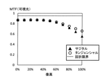
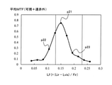
- FIG. 6 is a graph showing a simulation result of the imaging performance of the optical system 2 in the first embodiment.
- the vertical axis is the evaluation value of the average MTF (modulation transfer function).
- the average MTF is an average value of the MTF of the visible light L11 and the MTF of the far infrared light L12 as described later.
- the factor Lf of the above equation (1) was set to various values, and the optical design was optimized for each set value.
- software CODE-V manufactured by Synopsys was used.
- the average MTF was used from the viewpoint of evaluating both the imaging performance of the visible light L11 and the imaging performance of the far infrared light L12 in the designed optical system 2.
- the setting of the factor Lf was changed by an optical design in which the focal length Fir of the far-infrared light L12 and the air-equivalent length Lir were fixed, while the air-equivalent length Lvis of the visible light L11 was changed.
- FIGS. 7 and 8 The MTF of visible light L11 and the MTF of far-infrared light L12 in the average MTF of Example 1 are illustrated in FIGS. 7 and 8, respectively.
- the horizontal axis shows the image height as a percentage
- the vertical axis shows the calculated value of each MTF.
- the MTF curve in the sagittal direction, the MTF curve in the tangential direction, and the boundary line of the diffraction limit are illustrated.
- the wavelength ⁇ vis of the above-mentioned d-line and the high-frequency spatial frequency of 30 lp / mm were used (lp: line pairs).
- the wavelength ⁇ ir described above and the low frequency spatial frequency of 10 lp / mm were used.
- the pixel pitch of each of the image pickup sensors 11 and 12 was taken into consideration.
- the spatial frequency of the far-infrared MTF is set to be lower than the spatial frequency of the visible MTF. I set it.
- the average image heights of 0%, 30%, 60%, and 100% in the sagittal direction and the tangential direction in the MTF of visible light L11 and the MTF of far infrared light L12 obtained as shown in FIGS. 7 and 8, respectively.
- the average MTF was calculated by calculation. It is considered that the larger the average MTF is, the higher the imaging performance of the visible light L11 and the far infrared light L12 is.
- the graph of FIG. 6 it has a mountain-shaped raised graph shape in a numerical range such as the following equation (1a) including the numerical range of the conditional expression (1). 0.08 ⁇ (Lir-Lvis) /Fir ⁇ 0.28 ... (1a) Within the range of the above equation (1a), the average MTF in the optical system 2 of Example 1 satisfying the conditional equation (1) is significantly larger than the average MTF of Examples 2 and 3 not satisfying the conditional equation (1). .. As described above, it was confirmed that the conditional expression (1) can improve the imaging performance of the visible light L11 and the far infrared light L12.
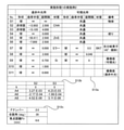
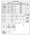
- FIG. 9 is a chart showing a numerical example 1 of the optical system 2 of the first embodiment.
- the chart of FIG. 9 includes surface data D11a of the optical system 2 of the first embodiment in the present embodiment, aspherical surface data D11b, and various data D11c.
- the surface data D11a indicates the shape, radius of curvature, surface spacing, and material of each surface S1 to S11 arranged in order in the optical system 2 from the object side, and is provided with a remarks column.
- the surface number S2 is a lens surface on the object side of the first lens element 31, and has an aspherical shape.
- the surface number S1 represents an object such as a subject 10 located at infinity (see the remarks column).
- the surface number S7 is the surface on the object side of the optical branching element 21, and after this surface, the surface through which the optical path of the visible light L11 and the optical path of the far infrared light L12 pass. And are shown respectively (see FIGS. 3 and 4).
- the aspherical surface data D11b shows various coefficients of the following equation (2) that define the aspherical surface shape for each surface S2 and S3 of the aspherical surface shape in the surface data D11a.
- h is the height in the radial direction
- k is the cornic constant
- An is the nth-order aspherical coefficient.
- n is an even number of 4 or more and 20 or less, and the sum of each n is taken.
- the sag amount z at the radial height h on the target surface is defined to be rotationally symmetric.
- the factor Lf and the average MTF of the conditional expression (1) are obtained as shown at the plot point p11 in FIG.
- FIG. 10 is a chart showing a numerical example 2 of the optical system 2 of the first embodiment.
- the chart of FIG. 10 includes the surface data D12a of the optical system 2 of the second embodiment in the present embodiment, the aspherical surface data D12b, and various data D12c.
- the data D12a to D12c show the same information as the data D11a to D11c of the first embodiment for the optical system 2 of the second embodiment of the present embodiment.
- the surface spacing of the surface data D12a with respect to the surface number S8 is changed from FIG. 9 in order to extend the air conversion length Lvis of the visible light L11 as compared with the first embodiment.
- the optical design such as the surface shape was optimized.
- the factor Lf and the average MTF shown at the plot point p12 in FIG. 6 are obtained.
- FIG. 11 is a chart showing a numerical example 3 of the optical system 2 of the first embodiment.
- the chart of FIG. 11 includes the surface data D13a of the optical system 2 of the third embodiment in the present embodiment, the aspherical surface data D13b, and various data D13c.
- the data D13a to D13c show the same information as the data D11a to D11c of the first embodiment for the optical system 2 of the third embodiment of the present embodiment.
- Example 3 of this embodiment contrary to Example 2, the air conversion length Lvis of visible light L11 was shortened as compared with Example 1 to optimize the optical design.
- the factor Lf and the average MTF shown at the plot point p13 in FIG. 6 are obtained.
- the factor Lf is not only at the plot points p11 of Example 1 but also at the plot points p12 and p13 of Examples 2 and 3.
- the imaging performance of both with the external light L12 can be improved.
- the optical system 2 in the present embodiment is connected to the image formation position P1 which is an example of the first image formation position by the visible light L11 as an example of the first light having a wavelength in the visible region. Image.
- the optical system 2 is formed by the far-infrared light L12 as an example of the second light having a wavelength in the far-infrared region at the image formation position P2 which is an example of the second image formation position.
- the optical system 2 includes a lens group 3 and an optical branching element 2.
- the lens group 3 has an optical axis Z0 extending rearward from the front where the visible light L11 and the far infrared light L12 are incident, a focal length Fvis of the visible light L11, and a focal length Fir of the far infrared light L12. Have.
- the optical branching element 21 is arranged behind the lens group 3, and branches the visible light L11 and the far-infrared light L12 from the lens group 3 to each other to guide the visible light L11 to the image formation position P1 and far-infrared.
- the external light L12 is guided to the image formation position P2.
- the lens group 3 is visible so that the image formation position P1 corresponds to the focal length Fvis of the visible light L11 and the image formation position P2 corresponds to the focal length Fir of the far infrared light L12 separately from the image formation position P1. It is composed of lens elements 31 and 32 that transmit light L11 and far-infrared light L12.
- the image formation position P1 of the visible light L11 and the image formation position P of the far infrared light L12 are set corresponding to the focal lengths Fvis and Fir of the lens group 3, respectively, and optical branching is performed.
- the lens group 3 in front of the element 2 constitutes both imaging optical systems. This makes it possible to simplify the configuration of the back focus behind the optical branching element 2 in the optical system 2, and to facilitate both visible imaging and far-infrared imaging, such as downsizing of the imaging device 2.
- the air conversion length Lvis which is an example of the first air conversion length through which the visible light L11 passes from the rear end position in the lens group 3, that is, the rear position P3 to the imaging position P1
- the infrared light L12 is shorter than the air equivalent length Lir, which is an example of the second air equivalent length that passes from the rear position P3 to the image formation position P2.
- the optical system 2 in the present embodiment is a conditional expression based on the air equivalent length Lvis of the visible light L11 in the back focus, the air equivalent length Lir of the far infrared light L12, and the focal length Fir of the far infrared light L12. (1) may be satisfied. This makes it possible to optimize the back focus in the optical system 2 and improve both the imaging performance of the visible light L11 and the imaging performance of the far-infrared light L12. Further, the optical system 2 in the present embodiment may satisfy the numerical range of the above equation (1a) instead of the conditional equation (1).
- the lens element is not provided behind the optical branching element 2, and the lens elements 31 and 32 of the lens group 3 are provided in front of the optical branching element 2.
- the optical system 2 can be miniaturized.
- the first lens element 31 in the lens group 3 is made of calcohalide glass.
- the optical system 2 having light transmission in the visible region and the far infrared region can be provided with a material that is easy to handle in various applications.
- the lens element of the calcohalide material is not particularly limited to the first lens element 31. Further, the first lens element 31 may be made of a lens material other than the calcohalide material.
- the optical branching element 21 has an optical characteristic of transmitting visible light L11 and reflecting far infrared light L12.
- the optical path of the far-infrared light L12 which may be longer than the optical path of the visible light L11, is bent (see FIGS. 3 and 4), and the optical system 2 can be easily miniaturized. Can be done.
- the image pickup apparatus 1 includes an optical system 2, a visible image pickup sensor 11 which is an example of a first image pickup unit, and a far infrared image pickup sensor 12 which is an example of a second image pickup unit.
- the visible image pickup sensor 11 is arranged at the image formation position P1 of the visible light L11 by the optical system 2 and captures an image by the visible light L11.
- the far-infrared imaging sensor 12 is arranged at the imaging position P2 of the far-infrared light L12 by the optical system 2 and acquires an image by the far-infrared light L12.
- the optical system 2 can reduce the size of the configuration for achieving both visible imaging and far-infrared imaging, and improve the imaging performance of both, making it easy to achieve both. can.
- the image pickup system 20 includes an image pickup device 1 and a control unit 15 that analyzes various images Im1 and Im2 captured by the image pickup device 1.
- the optical system 2 of the image pickup apparatus 1 makes it easy to perform both the analysis of the visible image Im1 and the analysis of the far-infrared image Im2.
- optical system according to the present embodiment will be described by omitting the description of the same configuration and operation as the optical system 2 and the image pickup apparatus 1 according to the first embodiment as appropriate.
- FIG. 12 shows the configuration of the optical system 2A according to the second embodiment.
- zinc sulfide is exemplified as the lens material of the second lens element 32.
- the lens material of the second lens element 32A is made of the same calcium halide glass as the first lens element 31.
- the lens group 3A can be formed of glass having high productivity and workability, and it is easy to use in various applications.
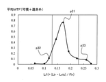
- FIG. 13 shows a graph of the simulation result of the imaging performance of the optical system 2A of the present embodiment.
- the optical design of the optical system 2A of the second embodiment was optimized by setting the factor Lf to various values as in the case of FIG. 6 of the first embodiment.
- Examples 1, 2, and 3 of the second embodiment correspond to plot points p21, p22, and p23 in the graph of FIG. 13, respectively.
- FIG. 14 shows the numerical embodiment 1 of the optical system 2A of the second embodiment in the same manner as the first embodiment.
- the surface data D21a, the aspherical surface data D21b, and the various data D21c in FIG. 14 provide information about the optical system 2A of the first embodiment in the present embodiment with the data D11a to D11c in FIG. It is shown in the same manner.
- the optical system 2A of this embodiment has a factor Lf satisfying the conditional expression (1) as shown in the plot point p21 of FIG.
- FIG. 15 shows the numerical embodiment 2 of the optical system 2A of the second embodiment in the same manner as the above embodiment.
- the surface data D22a, the aspherical surface data D22b, and the various data D22c in FIG. 15 show information about the optical system 2A of the second embodiment in the present embodiment, respectively.
- the optical system 2A of this embodiment has a factor Lf that is lower than the lower limit of the conditional expression (1).
- FIG. 16 shows the numerical embodiment 3 of the optical system 2A of the second embodiment in the same manner as the above embodiment.
- the data D23a, D23b, and D23c in FIG. 16 indicate information about the optical system 2A of the third embodiment in the present embodiment, respectively.
- the optical system 2A of this example has a factor Lf that exceeds that of Example 1 as shown in the plot point p23 of FIG.
- the average MTF between the visible light L11 and the far-infrared light L12 in the optical systems 2A of the first to third embodiments of the present embodiment has a range in which the factor Lf is defined by the conditional equation (1). It is especially high within. Similar to the first embodiment, the optical system 2A of the present embodiment can also improve the imaging performance of both the visible light L11 and the far infrared light L12 in a compact configuration.
- FIG. 17 shows the configuration of the optical system 2B according to the third embodiment.
- the optical system 2B according to the present embodiment further includes a third lens element 33 arranged behind the second lens element 32 in the lens group 3 in addition to the same configuration as the optical system 2 of the first embodiment.
- the third lens element 33 is made of a lens material that transmits visible light L11 and far infrared light L12, such as calcium halide CHA.
- numerical simulations of various examples were performed in the same manner as in the first and second embodiments.
- FIG. 18 shows a graph of the simulation result of the imaging performance of the optical system 2B of the present embodiment.
- FIG. 19 shows the numerical embodiment 1 of the optical system 2B of the third embodiment in the same manner as in each of the above embodiments.
- the surface data D31a, the aspherical surface data D31b, and the various data D31c in FIG. 19 show information about the optical system 2B of the first embodiment in the present embodiment, respectively.
- the average MTF in the optical systems 2B of the first to third embodiments of the present embodiment also has a particularly high factor Lf within the range of the conditional expression (1).
- the optical system 2B of the present embodiment can also improve the imaging performance of both the visible light L11 and the far infrared light L12, as in each of the above embodiments.
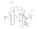
- FIG. 22 shows the configuration of the optical system 2C according to the fourth embodiment.
- the optical system 2C according to the present embodiment further includes a fourth lens element 34 arranged behind the first lens element 31 in the lens group 3 in addition to the same configuration as the optical system 2B of the third embodiment.
- the fourth lens element 34 is made of a lens material that transmits visible light L11 and far infrared light L12.
- numerical simulations of various examples were performed in the same manner as in the first to third embodiments.
- FIG. 23 shows a graph of the simulation result of the imaging performance of the optical system 2C of the present embodiment.
- the factors Lf 0.196 mm, 0.096 mm and 0.255 mm were set, respectively.
- FIGS. 24 to 26 show numerical examples 1 to 3 of the optical system 2C of the fourth embodiment in the same manner as in each of the above embodiments.
- the data D41a to D41c, D42a to D42c, and D43a to D43c in FIGS. 24, 25, and 26 show information about the optical system 2C of Examples 1, 2, and 3, respectively, in the present embodiment.
- the average MTF in the optical systems 2C of the first to third embodiments of the present embodiment also has a particularly high factor Lf within the range of the conditional expression (1).
- the optical system 2C of the present embodiment can also improve the imaging performance of both the visible light L11 and the far-infrared light L12, as in each of the above-described embodiments.
- the graph shape is flattened within the range of the conditional expression (1) as compared with FIG. 6 and the like. According to this embodiment, the number of lenses can be increased to facilitate improvement in imaging performance.
- the number of lenses in the lens group 3 of the optical system 2C is 4 or less has been described, but the number of lenses may be 5 or more. Even in this case, the imaging performance can be improved as in each of the above embodiments.
- Embodiments 1 to 4 have been described as examples of the techniques disclosed in the present application.
- the technique in the present disclosure is not limited to this, and can be applied to embodiments in which changes, substitutions, additions, omissions, etc. are made as appropriate. It is also possible to combine the components described in each of the above embodiments into a new embodiment. Therefore, other embodiments will be exemplified below.
- the optical systems 2, 2A to 2C in which the optical branching element 21 passes through the visible light L11 and reflects the far infrared light L12 are exemplified, but the present disclosure is not limited to this. An example of modification of this point will be described with reference to FIG. 27.
- FIG. 27 illustrates the configuration of the optical system 2D of the modified example of the first embodiment.
- the optical branching element 23 that reflects visible light L11 and transmits far infrared light L12 is provided. Be prepared.
- the optical branching element 23 of this modification is composed of a bandpass filter in which the wavelength band of the far infrared light L12 is set in advance as the transmission band.
- the far-infrared transmission filter 22 is arranged on the + Z side of, for example, the optical branching element 23.
- the optical system 2D of this modification in the incident light L10 emitted from the lens group 3 in the + Z direction, the visible light L11 is reflected by the optical branching element 23 and emitted in the + X direction, while the far infrared light L12 is optical branched. It passes through the element 23 and emits light in the + Z direction.
- the above-mentioned conditional expression (1) may be satisfied by the air conversion length Lvis of the optical path of the visible light L11 and the air conversion length Lir of the optical path of the far infrared light L12.
- the optical system 2D of the present modification can easily realize the image pickup apparatus 1 that achieves both visible imaging and far-infrared imaging.
- the optical branching elements 21 and 23 are configured by a bandpass filter.
- the optical branching elements 21 and 23 are not limited to the bandpass filter, and may be configured by various band splitters, for example, a highpass filter or a lowpass filter.
- the far-infrared transmittance filter 22 may be provided integrally with the far-infrared imaging sensor 12 or the optical branching element 21.
- the far-infrared transmission filter 22 may be omitted from the optical systems 2, 2A to 2D.
- an optical element other than the far-infrared transmission filter 22 is not arranged between the optical branching elements 21 and 23 and the imaging positions P1 and P2 .
- various optical elements may be arranged between the optical branching elements 21 and 23 and the imaging positions P1 and P2, for example, various wavelength filters, polarization filters, polarizing plates, mirrors and the like. It may be arranged.
- the optical systems 2, 2A to 2D including the aspherical lens surface are exemplified.
- the optical system of the present embodiment does not have to include an aspherical lens surface, and for example, all the lens elements included in the lens group 3 may be spherical lenses. Further, the optical system of the present embodiment may include a lens element having a free curved surface that is not rotationally symmetric in the lens group 3.
- the present disclosure is applicable to various applications that combine visible imaging and far-infrared imaging.
Abstract
An optical system (2) that forms an image at a first image formation position (P1) by first light (L11) in a visible range, and forms an image at a second image formation position (P2) by second light (L12) in a far-infrared range is provided with a lens group (3) and an optical division element (21). The lens group has an optical axis extending from the front on which the first and the second light are incident to the rear from which the first and the second light are emitted, the focal length of the first light, and the focal length of the second light. The optical division element is disposed at the rear of the lens group, divides the first and the second light from the lens group from each other, guides the first light to the first image formation position, and guides the second light to the second image formation position. The lens group comprises lens elements that transmit the first and the second light such that the first image formation position corresponds to the focal length of the first light, and separately from the first image formation position, the second image formation position corresponds to the focal length of the second light.
Description
本開示は、可視域における撮像と遠赤外域における撮像とを行う光学系および撮像装置、撮像システムに関する。
The present disclosure relates to an optical system, an imaging device, and an imaging system that perform imaging in the visible region and imaging in the far infrared region.
特許文献1は、熱画像カメラが可視光線と遠赤外線帯域を同時に撮影して鮮やかな画像を獲得することを目的とした、熱画像カメラ用の一軸型レンズモジュールを開示している。レンズモジュールは、被写体と相対する対物レンズと、対物レンズの後側に位置して、対物レンズを透過する光から遠赤外線は反射して可視光線は透過する光束分離器と、光束分離器の後側に位置する可視光線結像レンズと、遠赤外線結像レンズとを備える。可視光線結像レンズは、後側に位置するCCDセンサに、光束分離器からの可視光線で結像する。遠赤外線結像レンズは、光学像を熱画像信号に変換して出力する遠赤外線検出器に、光束分離器からの遠赤外線で結像する。
Patent Document 1 discloses a uniaxial lens module for a thermal image camera, which aims to acquire a vivid image by simultaneously capturing visible light and a far-infrared band with the thermal image camera. The lens module is located behind the objective lens facing the subject, the light beam separator that reflects far infrared rays from the light that passes through the objective lens and transmits visible light, and the light beam separator. It includes a visible light imaging lens located on the side and a far infrared imaging lens. The visible light imaging lens forms an image on the CCD sensor located on the rear side with visible light from the luminous flux separator. The far-infrared imaging lens forms an image with far-infrared rays from a light beam separator on a far-infrared detector that converts an optical image into a thermal image signal and outputs it.
本開示は、可視域における撮像と遠赤外域における撮像との両立を行い易くすることができる光学系および撮像装置、撮像システムを提供する。
The present disclosure provides an optical system, an imaging device, and an imaging system that can facilitate both imaging in the visible region and imaging in the far infrared region.
本開示における光学系は、可視域における波長を有する第1の光により第1の結像位置に結像し、遠赤外域における波長を有する第2の光により第2の結像位置に結像する光学系である。光学系は、レンズ群と、光分岐素子とを備える。レンズ群は、第1及び第2の光が入射する前方から出射する後方に延びた光軸と、第1の光の焦点距離と、第2の光の焦点距離とを有する。光分岐素子は、レンズ群の後方に配置され、レンズ群からの第1及び第2の光を互いに分岐して、第1の光を第1の結像位置に導光すると共に第2の光を第2の結像位置に導光する。レンズ群は、第1の結像位置を第1の光の焦点距離に対応させ、第1の結像位置とは別に第2の結像位置を第2の光の焦点距離に対応させるように、第1及び第2の光を透過するレンズ素子で構成される。
The optical system in the present disclosure is imaged at a first imaging position by a first light having a wavelength in the visible region and at a second imaging position by a second light having a wavelength in the far infrared region. It is an optical system. The optical system includes a lens group and an optical branching element. The lens group has an optical axis extending rearward from the front where the first and second lights are incident, a focal length of the first light, and a focal length of the second light. The optical branching element is arranged behind the lens group and branches the first and second lights from the lens group to each other to guide the first light to the first imaging position and the second light. Is guided to the second image formation position. In the lens group, the first image formation position corresponds to the focal length of the first light, and the second image formation position corresponds to the focal length of the second light separately from the first image formation position. , A lens element that transmits first and second light.
本開示における撮像装置は、上記の光学系と、第1の撮像部と、第2の撮像部とを備える。第1の撮像部は、第1の結像位置に配置され、第1の光による画像を撮像する。第2の撮像部は、第2の結像位置に配置され、第2の光による画像を撮像する。
The image pickup apparatus in the present disclosure includes the above optical system, a first image pickup unit, and a second image pickup unit. The first image pickup unit is arranged at the first image formation position and captures an image by the first light. The second image pickup unit is arranged at the second image formation position and captures an image by the second light.
本開示における撮像システムは、上記の撮像装置と、撮像装置において撮像された画像を解析する制御部とを備える。
The image pickup system in the present disclosure includes the above image pickup device and a control unit that analyzes an image captured by the image pickup device.
本開示の光学系および撮像装置によると、可視域における撮像と遠赤外域における撮像との両立を行い易くすることができる。
According to the optical system and the image pickup apparatus of the present disclosure, it is possible to facilitate both the image pickup in the visible region and the image pickup in the far infrared region.
以下、適宜図面を参照しながら、実施の形態を詳細に説明する。但し、必要以上に詳細な説明は省略する場合がある。例えば、既によく知られた事項の詳細説明や実質的に同一の構成に対する重複説明を省略する場合がある。これは、以下の説明が不必要に冗長になるのを避け、当業者の理解を容易にするためである。
Hereinafter, embodiments will be described in detail with reference to the drawings as appropriate. However, more detailed explanation than necessary may be omitted. For example, detailed explanations of already well-known matters and duplicate explanations for substantially the same configuration may be omitted. This is to avoid unnecessary redundancy of the following description and to facilitate the understanding of those skilled in the art.
なお、出願人は、当業者が本開示を十分に理解するために添付図面および以下の説明を提供するのであって、これらによって特許請求の範囲に記載の主題を限定することを意図するものではない。
It should be noted that the applicant is not intended to limit the subject matter described in the claims by those skilled in the art by providing the accompanying drawings and the following description in order to fully understand the present disclosure. do not have.
(実施形態1)
以下、本開示の実施形態1について、図面を参照しながら説明する。本実施形態では、可視域における撮像と遠赤外域における撮像を両立する撮像装置とその光学系について説明する。 (Embodiment 1)
Hereinafter, Embodiment 1 of the present disclosure will be described with reference to the drawings. In this embodiment, an image pickup device that achieves both image pickup in the visible region and image pickup in the far infrared region and an optical system thereof will be described.
1.撮像装置について
図1は、本実施形態に係る撮像装置1及び撮像システム20を説明するための図である。本実施形態の撮像システム20は、撮像装置1と、制御部15とを備える。 1. 1. About the image pickup device FIG. 1 is a diagram for explaining the image pickup device 1 and theimage pickup system 20 according to the present embodiment. The image pickup system 20 of the present embodiment includes an image pickup device 1 and a control unit 15.
図1は、本実施形態に係る撮像装置1及び撮像システム20を説明するための図である。本実施形態の撮像システム20は、撮像装置1と、制御部15とを備える。 1. 1. About the image pickup device FIG. 1 is a diagram for explaining the image pickup device 1 and the
本実施形態において、撮像装置1は、例えば図1に示すように、光学系2と、可視撮像センサ11と、遠赤外撮像センサ12と備える。本実施形態の撮像装置1は、可視域における撮像すなわち可視撮像と、遠赤外域における撮像すなわち遠赤外撮像とを、光学系2によって同軸で行うカメラデバイスである。例えば、可視域は波長400nm~750nmであり、遠赤外域は波長3μm~20μmである。例えばこうした可視域の一部と遠赤外域の一部とが、撮像装置1による可視撮像と遠赤外撮像との対象となる。例えば遠赤外域は7μm~12μmであってもよい。
In the present embodiment, the image pickup apparatus 1 includes an optical system 2, a visible image pickup sensor 11, and a far infrared image pickup sensor 12, as shown in FIG. 1, for example. The image pickup apparatus 1 of the present embodiment is a camera device that coaxially performs an image pickup in a visible region, that is, a visible image pickup, and an image pickup in a far infrared region, that is, a far infrared image pickup, by an optical system 2. For example, the visible region has a wavelength of 400 nm to 750 nm, and the far infrared region has a wavelength of 3 μm to 20 μm. For example, a part of the visible region and a part of the far-infrared region are the targets of the visible imaging and the far-infrared imaging by the image pickup apparatus 1. For example, the far infrared region may be 7 μm to 12 μm.
本実施形態の撮像装置1は、例えば遠赤外撮像を利用した熱画像化、人感センサ或いは暗視等と、可視撮像とを組み合わせるような種々の用途に適用可能である。例えば本システム20において、人物等の被写体10を検温して、同じ被写体10に個人認識を行うなどの画像解析が適用できる。本システム20の撮像装置1は、モバイル端末などの各種電子機器に組み込まれたり、ドローン又は車両等の移動体に搭載されたり、監視カメラ等のように設置されたりする等の各種適用例が考えられる。こうした種々の適用例において、撮像装置1の小型化が有用である。
The image pickup apparatus 1 of the present embodiment can be applied to various applications such as a combination of thermal imaging using far-infrared imaging, a motion sensor or night vision, and visible imaging. For example, in the present system 20, image analysis such as measuring the temperature of a subject 10 such as a person and performing individual recognition on the same subject 10 can be applied. The image pickup device 1 of this system 20 can be considered as various application examples such as being incorporated in various electronic devices such as mobile terminals, being mounted on a moving body such as a drone or a vehicle, or being installed like a surveillance camera or the like. Be done. In these various application examples, it is useful to reduce the size of the image pickup apparatus 1.
本実施形態の撮像装置1において、光学系2は、被写体10から入射する光L10を集光し、入射光L10における可視光L11を可視撮像センサ11に導光すると共に、入射光L10における遠赤外光L12を遠赤外撮像センサ12に導光する。こうした光学系2によると、撮像装置1における鏡筒が1つといった小型の装置構成が提供できる。本実施形態の光学系2は、更なる小型化が可能な構成を備える。光学系2の構成については後述する。
In the image pickup apparatus 1 of the present embodiment, the optical system 2 collects the light L10 incident from the subject 10 and guides the visible light L11 in the incident light L10 to the visible image pickup sensor 11 and far-infrared light in the incident light L10. The external light L12 is guided to the far infrared imaging sensor 12. According to such an optical system 2, it is possible to provide a small device configuration such as one lens barrel in the image pickup device 1. The optical system 2 of the present embodiment has a configuration capable of further miniaturization. The configuration of the optical system 2 will be described later.
可視撮像センサ11は、例えばCCD又はCMOSイメージセンサといった、可視域に受光感度を有するアモルファスシリコン等の材料で構成された各種の撮像素子である。可視撮像センサ11は、複数の画素が所定のピッチで配置された撮像面を有する。可視撮像センサ11の画素ピッチは、例えば3μm程度である。可視撮像センサ11は、可視光L11が光学系2を介して入射することにより撮像面に結像した画像を撮像して、可視域における撮像画像すなわち可視画像Im1を示す画像信号を生成する。可視撮像センサ11は、本実施形態における第1の撮像部の一例である。
The visible image sensor 11 is various image sensors made of a material such as amorphous silicon having a light receiving sensitivity in the visible region, such as a CCD or a CMOS image sensor. The visible image pickup sensor 11 has an image pickup surface in which a plurality of pixels are arranged at a predetermined pitch. The pixel pitch of the visible image pickup sensor 11 is, for example, about 3 μm. The visible imaging sensor 11 captures an image formed on the imaging surface by incident visible light L11 via the optical system 2, and generates an image signal indicating an image captured in the visible region, that is, a visible image Im1. The visible image pickup sensor 11 is an example of the first image pickup unit in the present embodiment.
遠赤外撮像センサ12は、例えばボロメータ、サーモパイル又はSOIダイオードなど、遠赤外域に受光感度を有する撮像素子である。遠赤外撮像センサ12は、複数の画素が所定のピッチで配置された撮像面を有する。遠赤外撮像センサ12の画素ピッチは、例えば10μm~300μmである。遠赤外撮像センサ12は、遠赤外光L12が光学系2を介して入射することにより撮像面に結像した画像を撮像して、遠赤外域における撮像画像すなわち遠赤外画像Im2を示す画像信号を生成する。遠赤外撮像センサ12は、本実施形態における第2の撮像部の一例である。
The far-infrared image sensor 12 is an image sensor having light-receiving sensitivity in the far-infrared region, such as a bolometer, a thermopile, or an SOI diode. The far-infrared image pickup sensor 12 has an image pickup surface in which a plurality of pixels are arranged at a predetermined pitch. The pixel pitch of the far-infrared imaging sensor 12 is, for example, 10 μm to 300 μm. The far-infrared image pickup sensor 12 captures an image formed on the image pickup surface by the far-infrared light L12 incident through the optical system 2, and shows an image taken in the far-infrared region, that is, a far-infrared image Im2. Generate an image signal. The far-infrared image pickup sensor 12 is an example of the second image pickup unit in the present embodiment.
以上のように構成される撮像装置1によると、可視画像Im1と遠赤外画像Im2とが、光学系2を用いた同軸の撮像結果として出力される。よって、本実施形態の撮像装置1によると、例えば可視画像Im1と遠赤外画像Im2の間で被写体10の像ズレを抑制でき、可視撮像と遠赤外撮像とを組み合わせる各種用途において解析し易い画像出力を得ることができる。
According to the image pickup apparatus 1 configured as described above, the visible image Im1 and the far infrared image Im2 are output as a coaxial image pickup result using the optical system 2. Therefore, according to the image pickup apparatus 1 of the present embodiment, for example, the image shift of the subject 10 can be suppressed between the visible image Im1 and the far infrared image Im2, and it is easy to analyze in various applications in which the visible image pickup and the far infrared image pickup are combined. Image output can be obtained.
本システム20において、制御部15は、撮像装置1から画像信号を受信して、受信した画像信号が示す各種画像Im1,Im2に基づき各種の画像解析を行う。制御部15は、例えば内部メモリに格納されたプログラムを実行することで種々の機能を実現するCPU又はMPU等を含む。制御部15は、所望の機能を実現するように設計された専用のハードウェア回路を含んでもよい。制御部15は、CPU、MPU、GPU、DSP、FPGA又はASIC等を含んでもよい。
In this system 20, the control unit 15 receives an image signal from the image pickup apparatus 1 and performs various image analyzes based on various images Im1 and Im2 indicated by the received image signal. The control unit 15 includes, for example, a CPU or an MPU that realizes various functions by executing a program stored in an internal memory. The control unit 15 may include a dedicated hardware circuit designed to realize a desired function. The control unit 15 may include a CPU, MPU, GPU, DSP, FPGA, ASIC, or the like.
例えば、本システム20の制御部15は、撮像装置1における可視撮像センサ11によって撮像された可視画像Im1に基づき被写体10の個人認識を行い、遠赤外撮像センサ12によって撮像された遠赤外画像Im2に基づき被写体10の温度を認識する。又、制御部15は、例えば各画像Im1,Im2における被写体10の位置に基づいて、可視画像Im1からの認識結果と遠赤外画像Im2からの認識結果とを互いに関連付けて、解析結果の情報として管理する。本システム20によると、撮像装置1の光学系2によって可視画像Im1と遠赤外画像Im2の間で同じ被写体10の像ズレを抑制できることから、制御部15は、上記のような情報管理を容易に実行できる。
For example, the control unit 15 of the system 20 personally recognizes the subject 10 based on the visible image Im1 captured by the visible image sensor 11 in the image pickup device 1, and the far infrared image captured by the far infrared image sensor 12. The temperature of the subject 10 is recognized based on Im2. Further, the control unit 15 correlates the recognition result from the visible image Im1 and the recognition result from the far infrared image Im2 with each other as information of the analysis result, for example, based on the position of the subject 10 in each image Im1 and Im2. to manage. According to the system 20, the optical system 2 of the image pickup apparatus 1 can suppress the image shift of the same subject 10 between the visible image Im1 and the far infrared image Im2, so that the control unit 15 can easily manage the information as described above. Can be executed.
本実施形態では、上記のように撮像装置1を小型化でき、且つ可視光L11と遠赤外光L12との双方で精度良く結像を行える光学系2を提供する。以下、本実施形態の光学系2の構成を説明する。
The present embodiment provides an optical system 2 that can reduce the size of the image pickup apparatus 1 as described above and can accurately form an image with both visible light L11 and far infrared light L12. Hereinafter, the configuration of the optical system 2 of the present embodiment will be described.
2.光学系について
図2は、実施形態1に係る光学系2の構成を示す図である。光学系2は、外部からの入射光L10が入射する光軸Z0を有するレンズ群3と、レンズ群3からの入射光L10を可視光L11と遠赤外光L12とに分岐する光分岐素子21と、遠赤外透過フィルタ22とを備える。以下、光学系2におけるレンズ群3の光軸Z0の方向をZ方向とし、Z方向に直交する2方向をX,Y方向とする。又、Z方向において光学系2から外部に向いた物体側を-Z側または前方とし、反対の像面側を+Z側または後方とする。 2. 2. About the optical system FIG. 2 is a diagram showing the configuration of theoptical system 2 according to the first embodiment. The optical system 2 includes a lens group 3 having an optical axis Z0 on which the incident light L10 from the outside is incident, and an optical branching element 21 that branches the incident light L10 from the lens group 3 into visible light L11 and far infrared light L12. And a far-infrared transmission filter 22. Hereinafter, the direction of the optical axis Z0 of the lens group 3 in the optical system 2 is defined as the Z direction, and the two directions orthogonal to the Z direction are defined as the X and Y directions. Further, the object side facing outward from the optical system 2 in the Z direction is defined as the −Z side or the front, and the opposite image plane side is defined as the + Z side or the rear.
図2は、実施形態1に係る光学系2の構成を示す図である。光学系2は、外部からの入射光L10が入射する光軸Z0を有するレンズ群3と、レンズ群3からの入射光L10を可視光L11と遠赤外光L12とに分岐する光分岐素子21と、遠赤外透過フィルタ22とを備える。以下、光学系2におけるレンズ群3の光軸Z0の方向をZ方向とし、Z方向に直交する2方向をX,Y方向とする。又、Z方向において光学系2から外部に向いた物体側を-Z側または前方とし、反対の像面側を+Z側または後方とする。 2. 2. About the optical system FIG. 2 is a diagram showing the configuration of the
光学系2は、+Z側すなわち後方において、可視光L11により結像する結像位置P1と、遠赤外光L12により結像する結像位置P2とを有する。可視撮像センサ11の撮像面は、光学系2による可視光L11の結像位置P1に配置される。遠赤外撮像センサ12の撮像面は、遠赤外光L12の結像位置P2に配置される。光学系2において、光分岐素子21は、レンズ群3と各撮像センサ11,12との間に設けられる。遠赤外透過フィルタ22は、光分岐素子21と遠赤外撮像センサ12との間に設けられる。
The optical system 2 has an image formation position P1 formed by visible light L11 and an image formation position P2 formed by far infrared light L12 on the + Z side, that is, behind. The imaging surface of the visible imaging sensor 11 is arranged at the imaging position P1 of the visible light L11 by the optical system 2. The imaging surface of the far-infrared imaging sensor 12 is arranged at the imaging position P2 of the far-infrared light L12. In the optical system 2, the optical branching element 21 is provided between the lens group 3 and the image pickup sensors 11 and 12. The far-infrared transmittance filter 22 is provided between the optical branching element 21 and the far-infrared image pickup sensor 12.
本実施形態の光学系2は、光分岐素子21と各撮像センサ11,12との間には、例えば屈折力を有するレンズ素子を設けないように構成される。この構成により、光学系2の全長又は部品点数等の観点から小型化ができ、光分岐後のレンズの調心工程が減り低コスト化ができる。本実施形態では、こうした小型構成において可視撮像と遠赤外撮像とを両立するために、光分岐素子21よりも-Z側(即ち前方)のレンズ群3が、入射光L10に含まれる可視光L11と遠赤外光L12との各々の結像光学系を構成する。換言すると、各結像位置P1,P2がレンズ群3の焦点距離に対応して設定される。
The optical system 2 of the present embodiment is configured so that, for example, a lens element having a refractive power is not provided between the optical branching element 21 and the image pickup sensors 11 and 12. With this configuration, the size can be reduced from the viewpoint of the total length of the optical system 2 or the number of parts, and the alignment process of the lens after optical branching can be reduced and the cost can be reduced. In the present embodiment, in order to achieve both visible imaging and far-infrared imaging in such a compact configuration, the lens group 3 on the −Z side (that is, in front of) the optical branching element 21 is included in the incident light L10. Each of L11 and far-infrared light L12 constitutes an imaging optical system. In other words, the imaging positions P1 and P2 are set corresponding to the focal length of the lens group 3.
光学系2におけるレンズ群3は、可視域と遠赤外域との双方において光透過性を有するレンズ材料で構成される。レンズ材料の屈折率の波長依存性より、レンズ群3の焦点距離は、結像の対象とする光の波長に応じて変動し得る。レンズ群3は、外部からの入射光L10に、焦点距離に応じた屈折力を作用させて、結像光学系として機能する。レンズ群3を透過後の入射光L10は、可視光L11及び遠赤外光L12を含み、光分岐素子21に入射する。可視光L11及び遠赤外光L12は、それぞれ本実施形態における第1及び第2の光の一例である。
The lens group 3 in the optical system 2 is composed of a lens material having light transmission in both the visible region and the far infrared region. Due to the wavelength dependence of the refractive index of the lens material, the focal length of the lens group 3 can vary depending on the wavelength of the light to be imaged. The lens group 3 functions as an imaging optical system by applying a refractive power according to the focal length to the incident light L10 from the outside. The incident light L10 after passing through the lens group 3 includes visible light L11 and far infrared light L12, and is incident on the optical branching element 21. Visible light L11 and far-infrared light L12 are examples of the first and second lights in the present embodiment, respectively.
実施形態1の光学系2において、レンズ群3は、2枚のレンズ素子31,32と、絞り30とを備える。レンズ群3においては、前方から順番に第1レンズ素子31と第2レンズ素子32とが、光軸Z0に沿って配置される。実施形態1では、レンズ材料の一例として、第1レンズ素子31がカルコハライドA(CHA)で構成され、第2レンズ素子32が硫化亜鉛(ZnS)で構成される(図5参照)。なお、図5では、別々の組成を有するカルコハライドガラスの3種類を例示しており、それぞれカルコハライドA,B,Cと称している。レンズ群3におけるレンズ材料は上記に限らず、可視域において可視撮像に用いる可視光L11の波長帯と、遠赤外域において遠赤外撮像に用いる遠赤外光L12の波長帯とを透過する各種材料であってもよい。例えば、レンズ材料が透過する波長帯は0.4μm~12μmであってもよい。
In the optical system 2 of the first embodiment, the lens group 3 includes two lens elements 31 and 32 and a diaphragm 30. In the lens group 3, the first lens element 31 and the second lens element 32 are arranged along the optical axis Z0 in order from the front. In the first embodiment, as an example of the lens material, the first lens element 31 is made of calcium halide A (CHA) and the second lens element 32 is made of zinc sulfide (ZnS) (see FIG. 5). Note that FIG. 5 illustrates three types of calcohalide glass having different compositions, which are referred to as calcohalide A, B, and C, respectively. The lens material in the lens group 3 is not limited to the above, and various types that transmit the wavelength band of visible light L11 used for visible imaging in the visible region and the wavelength band of far infrared light L12 used for far infrared imaging in the far infrared region. It may be a material. For example, the wavelength band transmitted by the lens material may be 0.4 μm to 12 μm.
絞り30は、例えば開口絞りであり、入射光L10における可視光L11及び遠赤外光L12の光量を制限する。絞り30は、実施形態1では第1及び第2レンズ素子31,32の間に配置される。絞り30は、レンズ群3のどの位置に配置されても良く、必ずしも光学系2に設けられなくてもよい。
The diaphragm 30 is, for example, an aperture diaphragm, and limits the amount of visible light L11 and far infrared light L12 in the incident light L10. The aperture 30 is arranged between the first and second lens elements 31 and 32 in the first embodiment. The diaphragm 30 may be arranged at any position in the lens group 3, and may not necessarily be provided in the optical system 2.
光分岐素子21は、例えば図2に示すように、-Z側からの入射光L10において、可視光L11を透過して+Z側に出射する一方、遠赤外光L12を反射して+X側に出射するように構成される。例えば、光分岐素子21は、光を選択的に透過する特定の波長帯(即ち透過帯)を有し、透過帯以外の光を反射する光学特性のバンドパスフィルタにおいて、予め可視光L11の波長帯を透過帯に設定して構成される。
As shown in FIG. 2, for example, the optical branching element 21 transmits visible light L11 and emits light to the + Z side in the incident light L10 from the −Z side, while reflecting far infrared light L12 to the + X side. It is configured to emit light. For example, the optical branching element 21 has a specific wavelength band (that is, a transmission band) that selectively transmits light, and is a bandpass filter having optical characteristics that reflects light other than the transmission band, and has a wavelength of visible light L11 in advance. It is configured by setting the band as a transparent band.
遠赤外透過フィルタ22は、例えば図2の構成例において光分岐素子21よりも+X側に配置され、遠赤外光L12を選択的に透過する。遠赤外透過フィルタ22は、例えば予め遠赤外光L12の波長帯を透過帯に設定したバンドパスフィルタなど、各種のフィルタ素子で構成される。
The far-infrared transmission filter 22 is arranged on the + X side of the optical branching element 21 in, for example, the configuration example of FIG. 2, and selectively transmits the far-infrared light L12. The far-infrared transmission filter 22 is composed of various filter elements such as a bandpass filter in which the wavelength band of the far-infrared light L12 is set in advance as the transmission band.
以上のような本実施形態の光学系2においては、レンズ群3の後方で可視光L11と遠赤外光L12とがそれぞれ光分岐素子21等を介して各結像位置P1,P2に到るまでのバックフォーカスを考慮して、結像光学系としてのレンズ群3が光学設計される。
In the optical system 2 of the present embodiment as described above, the visible light L11 and the far-infrared light L12 reach the respective imaging positions P1 and P2 behind the lens group 3 via the optical branching element 21 and the like, respectively. The lens group 3 as an imaging optical system is optically designed in consideration of the back focus up to.
2-1.バックフォーカスについて
本実施形態の光学系2におけるバックフォーカスについて、図3,4を用いて説明する。以下では、レンズ群3による可視光L11の焦点距離を「Fvis」とし、遠赤外光L12の焦点距離を「Fir」とする。 2-1. Back focus The back focus of theoptical system 2 of the present embodiment will be described with reference to FIGS. 3 and 4. In the following, the focal length of the visible light L11 by the lens group 3 is referred to as “Fvis”, and the focal length of the far infrared light L12 is referred to as “Fir”.
本実施形態の光学系2におけるバックフォーカスについて、図3,4を用いて説明する。以下では、レンズ群3による可視光L11の焦点距離を「Fvis」とし、遠赤外光L12の焦点距離を「Fir」とする。 2-1. Back focus The back focus of the
図3は、レンズ群3の後方位置P3からの可視光L11の光路を例示する。後方位置P3は、レンズ群3において最も後方のレンズ面における光軸Z0上の位置である。図3の光路では、レンズ群3において光軸Z0上の可視光L11が、後方位置P3から+Z方向に出射して、光分岐素子21に入射する。さらに、入射した可視光L11は、光分岐素子21内部を透過し、光分岐素子21から+Z方向に出射して、結像位置P1に到る。こうした光路の空気換算光路長すなわち空気換算長Lvisは、レンズ群3による可視光L11の焦点距離Fvisと対応している。
FIG. 3 illustrates an optical path of visible light L11 from the rear position P3 of the lens group 3. The rear position P3 is a position on the optical axis Z0 on the rearmost lens surface in the lens group 3. In the optical path of FIG. 3, visible light L11 on the optical axis Z0 in the lens group 3 is emitted from the rear position P3 in the + Z direction and is incident on the optical branching element 21. Further, the incident visible light L11 passes through the inside of the optical branching element 21 and is emitted from the optical branching element 21 in the + Z direction to reach the image formation position P1. The air-equivalent optical path length, that is, the air-equivalent length Lvis of such an optical path corresponds to the focal length Fvis of the visible light L11 by the lens group 3.
例えば光学系2の無限遠合焦状態においては、結像位置P1がレンズ群3の焦点に位置することから、空気換算長Lvisと焦点距離Fvis間の差分は、レンズ群3の後方位置P3と主点間の距離差で表される。又、有限の被写体距離による合焦状態においては、被写体距離が短いほど可視光L11の結像位置P1がレンズ群3の焦点から遠ざかり、その分だけバックフォーカスの空気換算長Lvisが延長する。
For example, in the infinite focus state of the optical system 2, since the image formation position P1 is located at the focal point of the lens group 3, the difference between the air conversion length Lvis and the focal length Fvis is the rear position P3 of the lens group 3. It is represented by the difference in distance between the principal points. Further, in the in-focus state due to a finite subject distance, the shorter the subject distance, the farther the image formation position P1 of the visible light L11 is from the focal point of the lens group 3, and the air equivalent length Lvis of the back focus is extended by that amount.
図4は、レンズ群3の後方位置P3からの遠赤外光L12の光路を例示する。当該光路では、レンズ群3において光軸Z0上の遠赤外光L12が、後方位置P3から可視光L11と同様に光分岐素子21に入射すると、光分岐素子21から+X方向に反射する。反射した遠赤外光L12は、遠赤外透過フィルタ22を透過して結像位置P2に到る。こうした光路の空気換算長Lirと、レンズ群3による遠赤外光L12の焦点距離Firとは、上述した可視光L11の場合と同様の対応関係を有する。
FIG. 4 illustrates the optical path of the far infrared light L12 from the rear position P3 of the lens group 3. In the optical path, when the far-infrared light L12 on the optical axis Z0 in the lens group 3 is incident on the optical branching element 21 from the rear position P3 in the same manner as the visible light L11, it is reflected from the optical branching element 21 in the + X direction. The reflected far-infrared light L12 passes through the far-infrared transmissive filter 22 and reaches the image formation position P2. The air-equivalent length Lir of such an optical path and the focal length Fir of the far-infrared light L12 by the lens group 3 have the same correspondence relationship as in the case of the visible light L11 described above.
本実施形態の光学系2においては、図3,4に示すようなバックフォーカスの各光路について、可視光L11の空気換算長Lvisが、遠赤外光L12の空気換算長Lirよりも短くなるように、レンズ群3が構成される。これにより、上述した小型構成の光学系2において、レンズ材料等の波長依存性を利用して、可視域と遠赤外域との双方で精度良く結像する性能を得やすい。
In the optical system 2 of the present embodiment, the air equivalent length Lvis of the visible light L11 is shorter than the air equivalent length Lir of the far infrared light L12 for each back focus optical path as shown in FIGS. In addition, the lens group 3 is configured. As a result, in the above-mentioned compact optical system 2, it is easy to obtain the performance of accurately forming an image in both the visible region and the far infrared region by utilizing the wavelength dependence of the lens material or the like.
2-1-1.バックフォーカスの最適化
更に、本実施形態における実施例1の光学系2では、以下の条件式(1)を満たすようにレンズ群3が構成される。
0.13<(Lir-Lvis)/Fir<0.23 …(1) 2-1-1. Optimization of back focus Further, in theoptical system 2 of the first embodiment in the present embodiment, the lens group 3 is configured so as to satisfy the following conditional expression (1).
0.13 <(Lir-Lvis) /Fir <0.23 ... (1)
更に、本実施形態における実施例1の光学系2では、以下の条件式(1)を満たすようにレンズ群3が構成される。
0.13<(Lir-Lvis)/Fir<0.23 …(1) 2-1-1. Optimization of back focus Further, in the
0.13 <(Lir-Lvis) /Fir <0.23 ... (1)
上式(1)の評価にあたり、可視光L11の波長としては、可視域の基準波長として一般的に用いられるd線の波長λvis=587nmを用いる。又、遠赤外光L12の波長としては、各種用途で利用し易いいわゆる大気の窓の中にあり、また常温の物質が遠赤外域で放出する光のピーク波長でもある波長λir=10μmを用いる。以下、上式(1)における中辺(Lir-Lvis)/Firを因子Lfという場合がある。
In the evaluation of the above equation (1), the wavelength λvis = 587 nm of the d line, which is generally used as the reference wavelength in the visible region, is used as the wavelength of the visible light L11. Further, as the wavelength of the far-infrared light L12, the wavelength λir = 10 μm, which is in the so-called atmospheric window that can be easily used for various purposes and is also the peak wavelength of the light emitted by a substance at room temperature in the far-infrared region, is used. .. Hereinafter, the middle side (Lir-Lvis) / Fir in the above equation (1) may be referred to as a factor Lf.
上式(1)を満たす光学系2によると、上述した小型構成においてバックフォーカスを最適化して、可視域と遠赤外域との双方の結像性能を向上することができる。条件式(1)についての知見を、図5を用いて説明する。
According to the optical system 2 satisfying the above equation (1), it is possible to optimize the back focus in the above-mentioned compact configuration and improve the imaging performance in both the visible region and the far infrared region. The knowledge about the conditional expression (1) will be described with reference to FIG.
図5は、各種のレンズ材料のデータを例示する図である。図5では、光学系2に適用可能な各種レンズ材料の例示として、各々の名称と、組成と、各波長λvis,λirの屈折率nvis,nirと、後述する比率Nrとを示す。
FIG. 5 is a diagram illustrating data of various lens materials. In FIG. 5, as an example of various lens materials applicable to the optical system 2, the names and compositions of each, the refractive indexes nvis and nir of each wavelength λvis and λir, and the ratio Nr described later are shown.
可視光L11の屈折率nvisと遠赤外光L12の屈折率nirとは、それぞれ図5に示すように、種々のレンズ材料において様々な値を有する。これに対して、上式(1)は、下記の知見のように、様々な波長依存性のレンズ材料において共通に見られる普遍的な特性を利用しており、レンズ材料及び枚数などに限定されない各種の光学系に適用可能である。
As shown in FIG. 5, the refractive index nvis of the visible light L11 and the refractive index ir of the far-infrared light L12 have various values in various lens materials, respectively. On the other hand, the above equation (1) utilizes the universal characteristics commonly found in various wavelength-dependent lens materials as shown in the following findings, and is not limited to the lens material and the number of lenses. It can be applied to various optical systems.
まず、上式(1)の因子Lfにおける空気換算長の差(Lir-Lvis)について、レンズ群3における主点の位置は、例えば波長別には殆ど変化しないと考えられる。このことから、空気換算長の差(Lir-Lvis)は、次式(11)のように、可視光L11の焦点距離Fvisと、遠赤外光L12の焦点距離Firとの間の差分で近似できる。
Lir-Lvis≒Fir-Fvis …(11) First, regarding the difference in air conversion length (Lirr-Lvis) in the factor Lf of the above equation (1), it is considered that the position of the principal point in thelens group 3 hardly changes for each wavelength, for example. From this, the difference in air conversion length (Lir-Lvis) is approximated by the difference between the focal length Fvis of visible light L11 and the focal length Fir of far infrared light L12, as in the following equation (11). can.
Lir-Lvis ≒ Fir-Fvis ... (11)
Lir-Lvis≒Fir-Fvis …(11) First, regarding the difference in air conversion length (Lirr-Lvis) in the factor Lf of the above equation (1), it is considered that the position of the principal point in the
Lir-Lvis ≒ Fir-Fvis ... (11)
また、各焦点距離Fvis,Firは、レンズ群3を薄肉のレンズと見なした場合におけるレンズメーカーの公式に基づき、次式(12)のように近似することができる。なお、Cはレンズの曲率によって規定される定数である。
Fvis≒C/(nvis-1)
Fir≒C/(nir-1) …(12) Further, the focal lengths Fvis and Fir can be approximated by the following equation (12) based on the lens manufacturer's formula when thelens group 3 is regarded as a thin-walled lens. Note that C is a constant defined by the curvature of the lens.
Fvis≈C / (nvis-1)
Fire ≒ C / (nir-1) ... (12)
Fvis≒C/(nvis-1)
Fir≒C/(nir-1) …(12) Further, the focal lengths Fvis and Fir can be approximated by the following equation (12) based on the lens manufacturer's formula when the
Fvis≈C / (nvis-1)
Fire ≒ C / (nir-1) ... (12)
上式(11),(12)によると、条件式(1)の因子Lfは、可視光L11と遠赤外光L12とについての各屈折率nvis,nirを用いて、次式(13)のように近似できる。
Lf≒(nvis-1)/(nir-1)-1 …(13) According to the above equations (11) and (12), the factor Lf of the conditional equation (1) is of the following equation (13) using the respective refractive indexes nvis and nir for the visible light L11 and the far infrared light L12. Can be approximated as follows.
Lf≈ (nvis-1) / (nir-1) -1 ... (13)
上式(13)の右辺において、各屈折率nvis,nirは、比率Nr=(nvis-1)/(nir-1)として含まれる。比率Nrは、例えば真空の屈折率n=1からの、遠赤外光L12の屈折率nirのずれと可視光L11の屈折率nvisのずれとの間の比率を示し、遠赤外域と可視域に亘る屈折率の変化といった大域的な物理特性と考えられる。
On the right side of the above equation (13), each refractive index nvis, nir is included as a ratio Nr = (nvis-1) / (nir-1). The ratio Nr indicates the ratio between the deviation of the refractive index nir of the far-infrared light L12 and the deviation of the refractive index nvis of the visible light L11 from, for example, the refractive index n = 1 of the vacuum, and represents the far-infrared region and the visible region. It is considered to be a global physical characteristic such as a change in the refractive index over.
上式(13)のような各屈折率nvis,nirの比率Nrによると、図5に示すように、様々なレンズ材料におけるバラツキが、各屈折率nvis,nir自体のバラツキよりも格段に小さい。このように、大域的な物理特性の比率Nrは、様々なレンズ材料において殆ど変わらず、ひいては比率Nrに基づく条件式(1)が普遍的に適用できると考えられる。
According to the ratio Nr of each refractive index nvis and nir as in the above equation (13), as shown in FIG. 5, the variation in various lens materials is much smaller than the variation of each refractive index nvis and nir itself. As described above, the ratio Nr of the global physical characteristics is almost unchanged in various lens materials, and it is considered that the conditional equation (1) based on the ratio Nr can be universally applied.
図5における上式(13)の右辺の最小値は、カルコハライドCHAによる「0.139」である。上式(13)は、光学系2を薄肉のレンズと見なす近似を用いている。実際の光学系2における上式(13)の左辺は、上記近似のような理想的な場合(すなわち上式(13)の右辺)よりも大きくなる傾向がある。上式(1)の数値範囲は、レンズ材料および枚数等の光学系の各種差異による実用上のバラツキを考慮して見出された。
The minimum value on the right side of the above equation (13) in FIG. 5 is "0.139" according to the calcohalide CHA. The above equation (13) uses an approximation that regards the optical system 2 as a thin-walled lens. The left side of the above equation (13) in the actual optical system 2 tends to be larger than the ideal case (that is, the right side of the above equation (13)) as in the above approximation. The numerical range of the above equation (1) was found in consideration of practical variations due to various differences in the optical system such as the lens material and the number of lenses.
2-1-2.結像性能のシミュレーション
以上のような条件式(1)による結像性能の効果が確認された光学系2の数値シミュレーションについて、図6~8を用いて説明する。 2-1-2. Simulation of Imaging Performance Numerical simulation of theoptical system 2 in which the effect of imaging performance by the above conditional expression (1) has been confirmed will be described with reference to FIGS. 6 to 8.
以上のような条件式(1)による結像性能の効果が確認された光学系2の数値シミュレーションについて、図6~8を用いて説明する。 2-1-2. Simulation of Imaging Performance Numerical simulation of the
図6は、実施形態1における光学系2の結像性能のシミュレーション結果を示すグラフである。図6において、横軸は条件式(1)における因子Lf(=(Lir-Lvis)/Fir)の設定値であり、縦軸は平均MTF(変調伝達関数)の評価値である。平均MTFは、後述するように可視光L11のMTFと遠赤外光L12のMTFの平均値である。
FIG. 6 is a graph showing a simulation result of the imaging performance of the optical system 2 in the first embodiment. In FIG. 6, the horizontal axis is the set value of the factor Lf (= (Lir-Lvis) / Fir) in the conditional expression (1), and the vertical axis is the evaluation value of the average MTF (modulation transfer function). The average MTF is an average value of the MTF of the visible light L11 and the MTF of the far infrared light L12 as described later.
図6の数値シミュレーションは、実施形態1における光学系2の構成において、上式(1)の因子Lfを様々な値に設定し、各々の設定値において光学設計の最適化を行った。この際、Synopsys社のソフトウェアCODE Vを用いた。また、設計された光学系2における可視光L11の結像性能と遠赤外光L12の結像性能との双方を評価する観点から、平均MTFを用いた。
In the numerical simulation of FIG. 6, in the configuration of the optical system 2 in the first embodiment, the factor Lf of the above equation (1) was set to various values, and the optical design was optimized for each set value. At this time, software CODE-V manufactured by Synopsys was used. Further, the average MTF was used from the viewpoint of evaluating both the imaging performance of the visible light L11 and the imaging performance of the far infrared light L12 in the designed optical system 2.
図6のグラフにおける各々のプロット点は、実施形態1の光学系2において異なった光学設計による別々の実施例に対応している。実施例1は、条件式(1)に規定された範囲内の因子Lf(=0.172)のプロット点p11に対応する。実施例2は同式(1)の下限値を下回る因子Lf(=0.124)のプロット点p12に対応し、実施例3は上限値を上回る因子Lf(=0.260)のプロット点p13に対応する。因子Lfの設定変更は、遠赤外光L12の焦点距離Fir及び空気換算長Lirを固定しながら、可視光L11の空気換算長Lvisを変化させる光学設計により行った。
Each plot point in the graph of FIG. 6 corresponds to a separate embodiment with different optical designs in the optical system 2 of embodiment 1. Example 1 corresponds to the plot point p11 of the factor Lf (= 0.172) within the range defined in the conditional expression (1). Example 2 corresponds to the plot point p12 of the factor Lf (= 0.124) below the lower limit of the same equation (1), and Example 3 corresponds to the plot point p13 of the factor Lf (= 0.260) above the upper limit. Corresponds to. The setting of the factor Lf was changed by an optical design in which the focal length Fir of the far-infrared light L12 and the air-equivalent length Lir were fixed, while the air-equivalent length Lvis of the visible light L11 was changed.
実施例1の平均MTFにおける可視光L11のMTFと遠赤外光L12のMTFとをそれぞれ図7,8に例示する。各図7,8において、横軸は像高を百分率で示し、縦軸は各々のMTFの算出値を示す。また、各図7,8では、サジタル方向のMTF曲線と、タンジェンシャル方向のMTF曲線と、回折限界の境界線とを図示している。
The MTF of visible light L11 and the MTF of far-infrared light L12 in the average MTF of Example 1 are illustrated in FIGS. 7 and 8, respectively. In FIGS. 7 and 8, the horizontal axis shows the image height as a percentage, and the vertical axis shows the calculated value of each MTF. Further, in FIGS. 7 and 8, the MTF curve in the sagittal direction, the MTF curve in the tangential direction, and the boundary line of the diffraction limit are illustrated.
図7に例示する可視光L11のMTFでは、上述したd線の波長λvisと、高周波の空間周波数30lp/mmとを用いた(lp:line pairs)。図8に例示する遠赤外光L12のMTFでは、上述した波長λirと、低周波の空間周波数10lp/mmとを用いた。こうした空間周波数の設定には、各撮像センサ11,12の画素ピッチを考慮した。即ち、遠赤外撮像センサ12の画素ピッチは、物理限界として可視撮像センサ11の画素ピッチよりも大きくなると考えられることから、遠赤外MTFの空間周波数を可視MTFの空間周波数よりも低周波に設定した。
In the MTF of visible light L11 illustrated in FIG. 7, the wavelength λvis of the above-mentioned d-line and the high-frequency spatial frequency of 30 lp / mm were used (lp: line pairs). In the MTF of the far infrared light L12 exemplified in FIG. 8, the wavelength λir described above and the low frequency spatial frequency of 10 lp / mm were used. In setting such a spatial frequency, the pixel pitch of each of the image pickup sensors 11 and 12 was taken into consideration. That is, since the pixel pitch of the far-infrared imaging sensor 12 is considered to be larger than the pixel pitch of the visible imaging sensor 11 as a physical limit, the spatial frequency of the far-infrared MTF is set to be lower than the spatial frequency of the visible MTF. I set it.
各図7,8のように得られる可視光L11のMTFと遠赤外光L12のMTFとにおいて、それぞれサジタル方向及びタンジェンシャル方向についての像高0%,30%,60%,100%の平均演算により、平均MTFを算出した。こうした平均MTFが大きいほど、可視光L11と遠赤外光L12の結像性能が高いと考えられる。
The average image heights of 0%, 30%, 60%, and 100% in the sagittal direction and the tangential direction in the MTF of visible light L11 and the MTF of far infrared light L12 obtained as shown in FIGS. 7 and 8, respectively. The average MTF was calculated by calculation. It is considered that the larger the average MTF is, the higher the imaging performance of the visible light L11 and the far infrared light L12 is.
図6のグラフによると、条件式(1)の数値範囲を包含する次式(1a)のような数値範囲において、山状に盛り上がったグラフ形状を有する。
0.08<(Lir-Lvis)/Fir<0.28 …(1a)
上式(1a)の範囲の中でも、条件式(1)を満たす実施例1の光学系2における平均MTFが、条件式(1)を満たさない実施例2,3の平均MTFよりも顕著に大きい。以上のように、条件式(1)によって可視光L11と遠赤外光L12の結像性能を向上できる効果が確認できた。 According to the graph of FIG. 6, it has a mountain-shaped raised graph shape in a numerical range such as the following equation (1a) including the numerical range of the conditional expression (1).
0.08 <(Lir-Lvis) /Fir <0.28 ... (1a)
Within the range of the above equation (1a), the average MTF in theoptical system 2 of Example 1 satisfying the conditional equation (1) is significantly larger than the average MTF of Examples 2 and 3 not satisfying the conditional equation (1). .. As described above, it was confirmed that the conditional expression (1) can improve the imaging performance of the visible light L11 and the far infrared light L12.
0.08<(Lir-Lvis)/Fir<0.28 …(1a)
上式(1a)の範囲の中でも、条件式(1)を満たす実施例1の光学系2における平均MTFが、条件式(1)を満たさない実施例2,3の平均MTFよりも顕著に大きい。以上のように、条件式(1)によって可視光L11と遠赤外光L12の結像性能を向上できる効果が確認できた。 According to the graph of FIG. 6, it has a mountain-shaped raised graph shape in a numerical range such as the following equation (1a) including the numerical range of the conditional expression (1).
0.08 <(Lir-Lvis) /Fir <0.28 ... (1a)
Within the range of the above equation (1a), the average MTF in the
2-2.数値実施例
以上のような実施形態1の光学系2の実施例1~3を示す数値実施例1~3について、図9~11を用いて説明する。 2-2. Numerical Examples Numerical Examples 1 to 3 showing Examples 1 to 3 of theoptical system 2 of the first embodiment as described above will be described with reference to FIGS. 9 to 11.
以上のような実施形態1の光学系2の実施例1~3を示す数値実施例1~3について、図9~11を用いて説明する。 2-2. Numerical Examples Numerical Examples 1 to 3 showing Examples 1 to 3 of the
図9は、実施形態1の光学系2の数値実施例1を示す図表である。図9の図表は、本実施形態における実施例1の光学系2の面データD11aと、非球面データD11bと、各種データD11cとを含む。
FIG. 9 is a chart showing a numerical example 1 of the optical system 2 of the first embodiment. The chart of FIG. 9 includes surface data D11a of the optical system 2 of the first embodiment in the present embodiment, aspherical surface data D11b, and various data D11c.
面データD11aは、物体側から光学系2において順番に並ぶ各面S1~S11について、各々の面の形状と、曲率半径と、面間隔と、材質とを示し、備考欄を付している。例えば、面番号S2は第1レンズ素子31の物体側のレンズ面であり、非球面形状を有する。なお、面番号S1は、無限遠に位置する被写体10等の物体を表す(備考欄参照)。又、図9の面データD11aでは、面番号S7が光分岐素子21の物体側の面であり、この面以降は、可視光L11の光路が通る面と遠赤外光L12の光路が通る面とをそれぞれ示す(図3,4参照)。
The surface data D11a indicates the shape, radius of curvature, surface spacing, and material of each surface S1 to S11 arranged in order in the optical system 2 from the object side, and is provided with a remarks column. For example, the surface number S2 is a lens surface on the object side of the first lens element 31, and has an aspherical shape. The surface number S1 represents an object such as a subject 10 located at infinity (see the remarks column). Further, in the surface data D11a of FIG. 9, the surface number S7 is the surface on the object side of the optical branching element 21, and after this surface, the surface through which the optical path of the visible light L11 and the optical path of the far infrared light L12 pass. And are shown respectively (see FIGS. 3 and 4).
非球面データD11bは、面データD11aにおける非球面形状の各面S2,S3について、非球面の形状を規定する次式(2)の各種係数を示す。
The aspherical surface data D11b shows various coefficients of the following equation (2) that define the aspherical surface shape for each surface S2 and S3 of the aspherical surface shape in the surface data D11a.

上式(2)において、hは径方向の高さであり、kはコーニック定数であり、Anはn次の非球面係数である。上式(2)の右辺第2項において、例えばnは4以上20以下の偶数であり、各nについての総和が取られる。上式(2)によると、対象とする面上の径方向の高さhにおけるサグ量zが、回転対称に規定される。
In the above equation (2), h is the height in the radial direction, k is the cornic constant, and An is the nth-order aspherical coefficient. In the second term on the right side of the above equation (2), for example, n is an even number of 4 or more and 20 or less, and the sum of each n is taken. According to the above equation (2), the sag amount z at the radial height h on the target surface is defined to be rotationally symmetric.
各種データD11cは、光学系2における絞り30のFナンバーと、全画角と、遠赤外光L12の焦点距離Firとを示す。又、本実施例の光学系2は、可視光L11の焦点距離Fvis=5.8mmを有する。
Various data D11c indicate the F number of the aperture 30 in the optical system 2, the total angle of view, and the focal length Fir of the far-infrared light L12. Further, the optical system 2 of this embodiment has a focal length Fvis = 5.8 mm of visible light L11.
上記の数値実施例によると、実施形態1の実施例1の光学系2は、バックフォーカスにおいて可視光L11の空気換算長Lvis=6.550mm及び遠赤外光L12の空気換算長Lir=7.721mmを有する。これにより、条件式(1)の因子Lf及び平均MTFが、図6のプロット点p11に示したように得られる。
According to the above numerical examples, in the optical system 2 of the first embodiment of the first embodiment, the air equivalent length Lvis = 6.550 mm of the visible light L11 and the air equivalent length Lir = 7. It has 721 mm. As a result, the factor Lf and the average MTF of the conditional expression (1) are obtained as shown at the plot point p11 in FIG.
図10は、実施形態1の光学系2の数値実施例2を示す図表である。図10の図表は、本実施形態における実施例2の光学系2の面データD12aと、非球面データD12bと、各種データD12cとを含む。各データD12a~D12cは、本実施形態の実施例2の光学系2について、実施例1の各データD11a~D11cと同様の情報を示す。
FIG. 10 is a chart showing a numerical example 2 of the optical system 2 of the first embodiment. The chart of FIG. 10 includes the surface data D12a of the optical system 2 of the second embodiment in the present embodiment, the aspherical surface data D12b, and various data D12c. The data D12a to D12c show the same information as the data D11a to D11c of the first embodiment for the optical system 2 of the second embodiment of the present embodiment.
本実施形態の実施例2では、実施例1よりも可視光L11の空気換算長Lvisを延長するべく、図10に示すように、面データD12aの面番号S8についての面間隔を図9から変更して、面形状などの光学設計を最適化した。実施形態1の実施例2の光学系2において、遠赤外光L12の空気換算長Lir及び焦点距離Firは実施例1と同じであり、可視光L11については空気換算長Lvis=6.879mmである。これにより、これにより、図6のプロット点p12に示した因子Lf及び平均MTFが得られる。
In the second embodiment of the present embodiment, as shown in FIG. 10, the surface spacing of the surface data D12a with respect to the surface number S8 is changed from FIG. 9 in order to extend the air conversion length Lvis of the visible light L11 as compared with the first embodiment. Then, the optical design such as the surface shape was optimized. In the optical system 2 of the second embodiment of the first embodiment, the air equivalent length Lir and the focal length Fir of the far infrared light L12 are the same as those of the first embodiment, and the visible light L11 has the air equivalent length Lvis = 6.879 mm. be. As a result, the factor Lf and the average MTF shown at the plot point p12 in FIG. 6 are obtained.
図11は、実施形態1の光学系2の数値実施例3を示す図表である。図11の図表は、本実施形態における実施例3の光学系2の面データD13aと、非球面データD13bと、各種データD13cとを含む。各データD13a~D13cは、本実施形態の実施例3の光学系2について、実施例1の各データD11a~D11cと同様の情報を示す。
FIG. 11 is a chart showing a numerical example 3 of the optical system 2 of the first embodiment. The chart of FIG. 11 includes the surface data D13a of the optical system 2 of the third embodiment in the present embodiment, the aspherical surface data D13b, and various data D13c. The data D13a to D13c show the same information as the data D11a to D11c of the first embodiment for the optical system 2 of the third embodiment of the present embodiment.
本実施形態の実施例3では、実施例2とは逆行して、実施例1よりも可視光L11の空気換算長Lvisを短縮して光学設計を最適化した。実施形態1の実施例3の光学系2において、遠赤外光L12の空気換算長Lir及び焦点距離Firは実施例1と同じであり、可視光L11については空気換算長Lvis=5.950mmである。これにより、これにより、図6のプロット点p13に示した因子Lf及び平均MTFが得られる。
In Example 3 of this embodiment, contrary to Example 2, the air conversion length Lvis of visible light L11 was shortened as compared with Example 1 to optimize the optical design. In the optical system 2 of the third embodiment of the first embodiment, the air equivalent length Lir and the focal length Fir of the far infrared light L12 are the same as those of the first embodiment, and the visible light L11 has the air equivalent length Lvis = 5.950 mm. be. As a result, the factor Lf and the average MTF shown at the plot point p13 in FIG. 6 are obtained.
以上のような各実施例1~3の光学系2によると、図6に示すように、実施例1のプロット点p11だけでなく実施例2,3のプロット点p12,p13においても、因子Lf=0の場合よりも高い平均MTFが得られている。よって、本実施形態の実施例1~3の光学系2によると、遠赤外光L12の空気換算長Lirよりも可視光L11の空気換算長Lvisを短くすることにより、可視光L11と遠赤外光L12との双方の結像性能を向上できる。
According to the optical system 2 of Examples 1 to 3 as described above, as shown in FIG. 6, the factor Lf is not only at the plot points p11 of Example 1 but also at the plot points p12 and p13 of Examples 2 and 3. A higher average MTF is obtained than in the case of = 0. Therefore, according to the optical system 2 of Examples 1 to 3 of the present embodiment, the visible light L11 and the far-infrared light L11 and the far-infrared light are obtained by making the air-equivalent length Lvis of the visible light L11 shorter than the air-equivalent length Lir of the far-infrared light L12. The imaging performance of both with the external light L12 can be improved.
3.まとめ
以上のように、本実施形態における光学系2は、可視域における波長を有する第1の光の一例としての可視光L11により、第1の結像位置の一例である結像位置P1に結像する。光学系2は、遠赤外域における波長を有する第2の光の一例としての遠赤外光L12により、第2の結像位置の一例である結像位置P2に結像する。光学系2は、レンズ群3と、光分岐素子2とを備える。レンズ群3は、可視光L11及び遠赤外光L12が入射する前方から出射する後方に延びた光軸Z0と、可視光L11の焦点距離Fvisと、遠赤外光L12の焦点距離Firとを有する。光分岐素子21は、レンズ群3の後方に配置され、レンズ群3からの可視光L11及び遠赤外光L12を互いに分岐して、可視光L11を結像位置P1に導光すると共に遠赤外光L12を結像位置P2に導光する。レンズ群3は、結像位置P1を可視光L11の焦点距離Fvisに対応させ、当該結像位置P1とは別に結像位置P2を遠赤外光L12の焦点距離Firに対応させるように、可視光L11及び遠赤外光L12を透過するレンズ素子31,32で構成される。 3. 3. Summary As described above, theoptical system 2 in the present embodiment is connected to the image formation position P1 which is an example of the first image formation position by the visible light L11 as an example of the first light having a wavelength in the visible region. Image. The optical system 2 is formed by the far-infrared light L12 as an example of the second light having a wavelength in the far-infrared region at the image formation position P2 which is an example of the second image formation position. The optical system 2 includes a lens group 3 and an optical branching element 2. The lens group 3 has an optical axis Z0 extending rearward from the front where the visible light L11 and the far infrared light L12 are incident, a focal length Fvis of the visible light L11, and a focal length Fir of the far infrared light L12. Have. The optical branching element 21 is arranged behind the lens group 3, and branches the visible light L11 and the far-infrared light L12 from the lens group 3 to each other to guide the visible light L11 to the image formation position P1 and far-infrared. The external light L12 is guided to the image formation position P2. The lens group 3 is visible so that the image formation position P1 corresponds to the focal length Fvis of the visible light L11 and the image formation position P2 corresponds to the focal length Fir of the far infrared light L12 separately from the image formation position P1. It is composed of lens elements 31 and 32 that transmit light L11 and far-infrared light L12.
以上のように、本実施形態における光学系2は、可視域における波長を有する第1の光の一例としての可視光L11により、第1の結像位置の一例である結像位置P1に結像する。光学系2は、遠赤外域における波長を有する第2の光の一例としての遠赤外光L12により、第2の結像位置の一例である結像位置P2に結像する。光学系2は、レンズ群3と、光分岐素子2とを備える。レンズ群3は、可視光L11及び遠赤外光L12が入射する前方から出射する後方に延びた光軸Z0と、可視光L11の焦点距離Fvisと、遠赤外光L12の焦点距離Firとを有する。光分岐素子21は、レンズ群3の後方に配置され、レンズ群3からの可視光L11及び遠赤外光L12を互いに分岐して、可視光L11を結像位置P1に導光すると共に遠赤外光L12を結像位置P2に導光する。レンズ群3は、結像位置P1を可視光L11の焦点距離Fvisに対応させ、当該結像位置P1とは別に結像位置P2を遠赤外光L12の焦点距離Firに対応させるように、可視光L11及び遠赤外光L12を透過するレンズ素子31,32で構成される。 3. 3. Summary As described above, the
以上の光学系2によると、可視光L11の結像位置P1と遠赤外光L12の結像位置Pとが、レンズ群3の各焦点距離Fvis,Firにそれぞれ対応して設定され、光分岐素子2よりも前方のレンズ群3が双方の結像光学系を構成する。これにより、光学系2において光分岐素子2後方のバックフォーカスの構成を簡素化でき、撮像装置2の小型化など、可視撮像と遠赤外撮像との両立を行い易くすることができる。
According to the above optical system 2, the image formation position P1 of the visible light L11 and the image formation position P of the far infrared light L12 are set corresponding to the focal lengths Fvis and Fir of the lens group 3, respectively, and optical branching is performed. The lens group 3 in front of the element 2 constitutes both imaging optical systems. This makes it possible to simplify the configuration of the back focus behind the optical branching element 2 in the optical system 2, and to facilitate both visible imaging and far-infrared imaging, such as downsizing of the imaging device 2.
本実施形態の光学系2において、可視光L11がレンズ群3における後端の位置すなわち後方位置P3から結像位置P1まで通過する第1の空気換算長の一例である空気換算長Lvisは、遠赤外光L12が後方位置P3から結像位置P2まで通過する第2の空気換算長の一例である空気換算長Lirよりも短い。これにより、可視光L11の結像性能と遠赤外光L12の結像性能との双方をレンズ群3により確保し易い。
In the optical system 2 of the present embodiment, the air conversion length Lvis, which is an example of the first air conversion length through which the visible light L11 passes from the rear end position in the lens group 3, that is, the rear position P3 to the imaging position P1, is far. The infrared light L12 is shorter than the air equivalent length Lir, which is an example of the second air equivalent length that passes from the rear position P3 to the image formation position P2. As a result, it is easy to secure both the imaging performance of the visible light L11 and the imaging performance of the far infrared light L12 by the lens group 3.
本実施形態における光学系2は、バックフォーカスにおける可視光L11の空気換算長Lvisと、遠赤外光L12の空気換算長Lirと、遠赤外光L12の焦点距離Firとに基づいて、条件式(1)を満たしてもよい。これにより、光学系2におけるバックフォーカスを最適化して、可視光L11の結像性能と遠赤外光L12の結像性能との双方を向上できる。又、本実施形態における光学系2は、条件式(1)の代わりに、上式(1a)の数値範囲を満たしてもよい。
The optical system 2 in the present embodiment is a conditional expression based on the air equivalent length Lvis of the visible light L11 in the back focus, the air equivalent length Lir of the far infrared light L12, and the focal length Fir of the far infrared light L12. (1) may be satisfied. This makes it possible to optimize the back focus in the optical system 2 and improve both the imaging performance of the visible light L11 and the imaging performance of the far-infrared light L12. Further, the optical system 2 in the present embodiment may satisfy the numerical range of the above equation (1a) instead of the conditional equation (1).
本実施形態における光学系2は、可視光L11の波長がλvis=587nmであり、遠赤外光L12の波長がλir=10μmである場合に条件式(1)を満たしてもよい。こうした波長λvis,λvisは、それぞれ可視撮像及び遠赤外撮像において有用である。
The optical system 2 in the present embodiment may satisfy the conditional expression (1) when the wavelength of the visible light L11 is λvis = 587 nm and the wavelength of the far infrared light L12 is λir = 10 μm. These wavelengths λvis and λvis are useful in visible imaging and far-infrared imaging, respectively.
本実施形態における光学系2は、光分岐素子2の後方にはレンズ素子が設けられず、光分岐素子2の前方にレンズ群3のレンズ素子31,32が設けられる。これにより、光学系2を小型化することができる。
In the optical system 2 of the present embodiment, the lens element is not provided behind the optical branching element 2, and the lens elements 31 and 32 of the lens group 3 are provided in front of the optical branching element 2. As a result, the optical system 2 can be miniaturized.
本実施形態の光学系2において、レンズ群3における第1レンズ素子31は、カルコハライドガラスで構成される。これにより、可視域と遠赤外域とに光透過性を有する光学系2が、各種用途において取り扱い易い材質で提供できる。カルコハライド材料のレンズ素子は、特に第1レンズ素子31に限らない。また、第1レンズ素子31は、カルコハライド材料でないレンズ材料で構成されてもよい。
In the optical system 2 of the present embodiment, the first lens element 31 in the lens group 3 is made of calcohalide glass. Thereby, the optical system 2 having light transmission in the visible region and the far infrared region can be provided with a material that is easy to handle in various applications. The lens element of the calcohalide material is not particularly limited to the first lens element 31. Further, the first lens element 31 may be made of a lens material other than the calcohalide material.
本実施形態の光学系2において、光分岐素子21は、可視光L11を透過し、遠赤外光L12を反射する光学特性を有する。これにより、光学系2のバックフォーカスにおいて、可視光L11の光路よりも長い場合が考えられる遠赤外光L12の光路を屈曲させ(図3,4参照)、光学系2を小型化し易くすることができる。
In the optical system 2 of the present embodiment, the optical branching element 21 has an optical characteristic of transmitting visible light L11 and reflecting far infrared light L12. As a result, in the back focus of the optical system 2, the optical path of the far-infrared light L12, which may be longer than the optical path of the visible light L11, is bent (see FIGS. 3 and 4), and the optical system 2 can be easily miniaturized. Can be done.
本実施形態において、撮像装置1は、光学系2と、第1の撮像部の一例である可視撮像センサ11と、第2の撮像部の一例である遠赤外撮像センサ12とを備える。可視撮像センサ11は、光学系2による可視光L11の結像位置P1に配置され、可視光L11による画像を撮像する。遠赤外撮像センサ12は、光学系2による遠赤外光L12の結像位置P2に配置され、遠赤外光L12による画像を撮像する。本実施形態の撮像装置1によると、光学系2により、可視撮像と遠赤外撮像を両立する構成を小型化したり、双方の結像性能を良くしたりでき、こうした両立を行い易くすることができる。
In the present embodiment, the image pickup apparatus 1 includes an optical system 2, a visible image pickup sensor 11 which is an example of a first image pickup unit, and a far infrared image pickup sensor 12 which is an example of a second image pickup unit. The visible image pickup sensor 11 is arranged at the image formation position P1 of the visible light L11 by the optical system 2 and captures an image by the visible light L11. The far-infrared imaging sensor 12 is arranged at the imaging position P2 of the far-infrared light L12 by the optical system 2 and acquires an image by the far-infrared light L12. According to the image pickup apparatus 1 of the present embodiment, the optical system 2 can reduce the size of the configuration for achieving both visible imaging and far-infrared imaging, and improve the imaging performance of both, making it easy to achieve both. can.
本実施形態において、撮像システム20は、撮像装置1と、撮像装置1において撮像された各種画像Im1,Im2を解析する制御部15とを備える。本システム20によると、撮像装置1の光学系2により、可視画像Im1の解析と遠赤外画像Im2の解析との両立を行い易くすることができる。
In the present embodiment, the image pickup system 20 includes an image pickup device 1 and a control unit 15 that analyzes various images Im1 and Im2 captured by the image pickup device 1. According to this system 20, the optical system 2 of the image pickup apparatus 1 makes it easy to perform both the analysis of the visible image Im1 and the analysis of the far-infrared image Im2.
(実施形態2)
以下、図12~16を用いて実施形態2を説明する。実施形態1では、光学系2における2枚のレンズ素子31,32間でレンズ材料が異なる例を説明した。実施形態2では、レンズ材料が同じレンズ素子で構成される光学系について説明する。 (Embodiment 2)
Hereinafter, the second embodiment will be described with reference to FIGS. 12 to 16. In the first embodiment, an example in which the lens material is different between the two lens elements 31 and 32 in the optical system 2 has been described. In the second embodiment, an optical system in which the lens material is composed of the same lens element will be described.
以下、図12~16を用いて実施形態2を説明する。実施形態1では、光学系2における2枚のレンズ素子31,32間でレンズ材料が異なる例を説明した。実施形態2では、レンズ材料が同じレンズ素子で構成される光学系について説明する。 (Embodiment 2)
Hereinafter, the second embodiment will be described with reference to FIGS. 12 to 16. In the first embodiment, an example in which the lens material is different between the two
以下、実施形態1に係る光学系2及び撮像装置1と同様の構成、動作の説明は適宜、省略して、本実施形態に係る光学系を説明する。
Hereinafter, the optical system according to the present embodiment will be described by omitting the description of the same configuration and operation as the optical system 2 and the image pickup apparatus 1 according to the first embodiment as appropriate.
図12は、実施形態2に係る光学系2Aの構成を示す。実施形態1では、第2レンズ素子32のレンズ材料として硫化亜鉛を例示した。本実施形態に係る光学系2Aでは、実施形態1の光学系2と同様の構成において、第2レンズ素子32Aのレンズ材料が、第1レンズ素子31と同じカルコハライドガラスで構成される。本実施形態の光学系2Aによると、生産性や加工性の高いガラスでレンズ群3Aを構成でき、各種用途において利用し易い。
FIG. 12 shows the configuration of the optical system 2A according to the second embodiment. In the first embodiment, zinc sulfide is exemplified as the lens material of the second lens element 32. In the optical system 2A according to the present embodiment, in the same configuration as the optical system 2 of the first embodiment, the lens material of the second lens element 32A is made of the same calcium halide glass as the first lens element 31. According to the optical system 2A of the present embodiment, the lens group 3A can be formed of glass having high productivity and workability, and it is easy to use in various applications.
図13は、本実施形態の光学系2Aの結像性能のシミュレーション結果のグラフを示す。図13の数値シミュレーションは、実施形態2の光学系2Aについて、実施形態1の図6と同様に因子Lfを様々な値に設定して光学設計を最適化した。実施形態2の実施例1,2,3は、それぞれ図13のグラフにおけるプロット点p21,p22,p23に対応する。
FIG. 13 shows a graph of the simulation result of the imaging performance of the optical system 2A of the present embodiment. In the numerical simulation of FIG. 13, the optical design of the optical system 2A of the second embodiment was optimized by setting the factor Lf to various values as in the case of FIG. 6 of the first embodiment. Examples 1, 2, and 3 of the second embodiment correspond to plot points p21, p22, and p23 in the graph of FIG. 13, respectively.
図14は、実施形態2の光学系2Aの数値実施例1を、実施形態1と同様に示す。具体的に、図14における面データD21aと、非球面データD21bと、各種データD21cとが、それぞれ本実施形態における実施例1の光学系2Aについての情報を、図9の各データD11a~D11cと同様に示す。本実施例の光学系2Aは、図13のプロット点p21に示すように、条件式(1)を満たす因子Lfを有する。
FIG. 14 shows the numerical embodiment 1 of the optical system 2A of the second embodiment in the same manner as the first embodiment. Specifically, the surface data D21a, the aspherical surface data D21b, and the various data D21c in FIG. 14 provide information about the optical system 2A of the first embodiment in the present embodiment with the data D11a to D11c in FIG. It is shown in the same manner. The optical system 2A of this embodiment has a factor Lf satisfying the conditional expression (1) as shown in the plot point p21 of FIG.
図15は、実施形態2の光学系2Aの数値実施例2を、上記実施例と同様に示す。図15における面データD22aと、非球面データD22bと、各種データD22cとが、それぞれ本実施形態における実施例2の光学系2Aについての情報を示す。本実施例の光学系2Aは、図13のプロット点p22に示すように、条件式(1)の下限値を下回る因子Lfを有する。
FIG. 15 shows the numerical embodiment 2 of the optical system 2A of the second embodiment in the same manner as the above embodiment. The surface data D22a, the aspherical surface data D22b, and the various data D22c in FIG. 15 show information about the optical system 2A of the second embodiment in the present embodiment, respectively. As shown in the plot point p22 of FIG. 13, the optical system 2A of this embodiment has a factor Lf that is lower than the lower limit of the conditional expression (1).
図16は、実施形態2の光学系2Aの数値実施例3を、上記実施例と同様に示す。図16における各データD23a,D23b,D23cが、それぞれ本実施形態における実施例3の光学系2Aについての情報を示す。本実施例の光学系2Aは、図13のプロット点p23に示すように、実施例1を上回る因子Lfを有する。
FIG. 16 shows the numerical embodiment 3 of the optical system 2A of the second embodiment in the same manner as the above embodiment. The data D23a, D23b, and D23c in FIG. 16 indicate information about the optical system 2A of the third embodiment in the present embodiment, respectively. The optical system 2A of this example has a factor Lf that exceeds that of Example 1 as shown in the plot point p23 of FIG.
本実施形態の各実施例1~3の光学系2Aにおける可視光L11と遠赤外光L12間の平均MTFは、図13に示すように、因子Lfが条件式(1)によって規定される範囲内で特に高くなっている。本実施形態の光学系2Aによっても、実施形態1と同様に、小型構成において可視光L11と遠赤外光L12との双方の結像性能を良くすることができる。
As shown in FIG. 13, the average MTF between the visible light L11 and the far-infrared light L12 in the optical systems 2A of the first to third embodiments of the present embodiment has a range in which the factor Lf is defined by the conditional equation (1). It is especially high within. Similar to the first embodiment, the optical system 2A of the present embodiment can also improve the imaging performance of both the visible light L11 and the far infrared light L12 in a compact configuration.
(実施形態3)
以下、図17~21を用いて実施形態3を説明する。実施形態1,2では、レンズ群3におけるレンズ枚数が2枚で焦点距離Fir=6.8mmの例を説明したが、本開示はこれに限定されない。実施形態3では、レンズ枚数が3枚で焦点距離Fir=15mmの例を説明する。 (Embodiment 3)
Hereinafter, the third embodiment will be described with reference to FIGS. 17 to 21. In the first and second embodiments, an example in which the number of lenses in thelens group 3 is two and the focal length is Fir = 6.8 mm has been described, but the present disclosure is not limited to this. In the third embodiment, an example in which the number of lenses is three and the focal length is Fir = 15 mm will be described.
以下、図17~21を用いて実施形態3を説明する。実施形態1,2では、レンズ群3におけるレンズ枚数が2枚で焦点距離Fir=6.8mmの例を説明したが、本開示はこれに限定されない。実施形態3では、レンズ枚数が3枚で焦点距離Fir=15mmの例を説明する。 (Embodiment 3)
Hereinafter, the third embodiment will be described with reference to FIGS. 17 to 21. In the first and second embodiments, an example in which the number of lenses in the
以下、実施形態1,2と同様の説明は適宜、省略して、本実施形態に係る光学系を説明する。
Hereinafter, the same description as in the first and second embodiments will be omitted as appropriate, and the optical system according to the present embodiment will be described.
図17は、実施形態3に係る光学系2Bの構成を示す。本実施形態に係る光学系2Bは、実施形態1の光学系2と同様の構成に加えて、レンズ群3において第2レンズ素子32の後方に配置された第3レンズ素子33をさらに備える。第3レンズ素子33は、例えばカルコハライドCHA等、可視光L11及び遠赤外光L12を透過するレンズ材料で構成される。こうした本実施形態の光学系2Bについても、実施形態1,2と同様に各種実施例の数値シミュレーションを行った。
FIG. 17 shows the configuration of the optical system 2B according to the third embodiment. The optical system 2B according to the present embodiment further includes a third lens element 33 arranged behind the second lens element 32 in the lens group 3 in addition to the same configuration as the optical system 2 of the first embodiment. The third lens element 33 is made of a lens material that transmits visible light L11 and far infrared light L12, such as calcium halide CHA. For the optical system 2B of the present embodiment, numerical simulations of various examples were performed in the same manner as in the first and second embodiments.
図18は、本実施形態の光学系2Bの結像性能のシミュレーション結果のグラフを示す。実施形態3の実施例1,2,3では、図18のグラフにおけるプロット点p31,p32,p33に示すように、それぞれ因子Lf=0.182mm,0.111mm,0.260mmに設定した。
FIG. 18 shows a graph of the simulation result of the imaging performance of the optical system 2B of the present embodiment. In Examples 1, 2 and 3 of the third embodiment, the factors Lf = 0.182 mm, 0.111 mm and 0.260 mm were set as shown in the plot points p31, p32 and p33 in the graph of FIG. 18, respectively.
図19は、実施形態3の光学系2Bの数値実施例1を、上記各実施形態と同様に示す。図19における面データD31aと、非球面データD31bと、各種データD31cとが、それぞれ本実施形態における実施例1の光学系2Bについての情報を示す。本実施例の光学系2Bは、バックフォーカスにおいて可視光L11の空気換算長Lvis=15.159mm及び遠赤外光L12の空気換算長Lir=17.889mmを有し、条件式(1)を満たす。
FIG. 19 shows the numerical embodiment 1 of the optical system 2B of the third embodiment in the same manner as in each of the above embodiments. The surface data D31a, the aspherical surface data D31b, and the various data D31c in FIG. 19 show information about the optical system 2B of the first embodiment in the present embodiment, respectively. The optical system 2B of this embodiment has an air equivalent length Lvis = 15.159 mm for visible light L11 and an air equivalent length Lir = 17.889 mm for far infrared light L12 in back focus, and satisfies the conditional equation (1). ..
図20,21は、それぞれ実施形態3の光学系2Bの数値実施例2,3を、上記実施例と同様に示す。図20,21における各データD32a~D32c,D33a~D33cが、それぞれ本実施形態における実施例2,3の光学系2Bについての情報を示す。実施例2の光学系2Bは、実施例1と同じ遠赤外光L12の空気換算長Lirと、可視光L11の空気換算長Lvis=16.219mmとを有し、条件式(1)の下限値を下回る。実施例3の光学系2Bは、可視光L11の空気換算長Lvis=16.829mmと、遠赤外光L12の空気換算長Lir=20.724mmとを有し、条件式(1)の上限値を上回る。
20 and 21 show numerical examples 2 and 3 of the optical system 2B of the third embodiment, respectively, in the same manner as the above-mentioned examples. The data D32a to D32c and D33a to D33c in FIGS. 20 and 21 show information about the optical system 2B of Examples 2 and 3 in the present embodiment, respectively. The optical system 2B of the second embodiment has the same air equivalent length Lir of the far infrared light L12 and the air equivalent length Lvis = 16.219 mm of the visible light L11 as in the first embodiment, and has the lower limit of the conditional expression (1). Below the value. The optical system 2B of the third embodiment has an air equivalent length Lvis = 16.829 mm of the visible light L11 and an air equivalent length Lir = 20.724 mm of the far infrared light L12, and has an upper limit value of the conditional expression (1). Exceeds.
本実施形態の各実施例1~3の光学系2Bにおける平均MTFも、図18に示すように、因子Lfが条件式(1)の範囲内で特に高くなっている。本実施形態の光学系2Bによっても、上記各実施形態と同様に可視光L11と遠赤外光L12との双方の結像性能を良くすることができる。
As shown in FIG. 18, the average MTF in the optical systems 2B of the first to third embodiments of the present embodiment also has a particularly high factor Lf within the range of the conditional expression (1). The optical system 2B of the present embodiment can also improve the imaging performance of both the visible light L11 and the far infrared light L12, as in each of the above embodiments.
(実施形態4)
以下、図22~26を用いて実施形態4を説明する。実施形態4では、実施形態3よりも更にレンズ枚数が多い例を説明する。 (Embodiment 4)
Hereinafter, the fourth embodiment will be described with reference to FIGS. 22 to 26. In the fourth embodiment, an example in which the number of lenses is larger than that in the third embodiment will be described.
以下、図22~26を用いて実施形態4を説明する。実施形態4では、実施形態3よりも更にレンズ枚数が多い例を説明する。 (Embodiment 4)
Hereinafter, the fourth embodiment will be described with reference to FIGS. 22 to 26. In the fourth embodiment, an example in which the number of lenses is larger than that in the third embodiment will be described.
以下、実施形態1~3と同様の説明は適宜、省略して、本実施形態に係る光学系を説明する。
Hereinafter, the same description as in the first to third embodiments will be omitted as appropriate, and the optical system according to the present embodiment will be described.
図22は、実施形態4に係る光学系2Cの構成を示す。本実施形態に係る光学系2Cは、実施形態3の光学系2Bと同様の構成に加えて、レンズ群3において第1レンズ素子31の後方に配置された第4レンズ素子34をさらに備える。第4レンズ素子34は、可視光L11及び遠赤外光L12を透過するレンズ材料で構成される。こうした本実施形態の光学系2Cについても、実施形態1~3と同様に各種実施例の数値シミュレーションを行った。
FIG. 22 shows the configuration of the optical system 2C according to the fourth embodiment. The optical system 2C according to the present embodiment further includes a fourth lens element 34 arranged behind the first lens element 31 in the lens group 3 in addition to the same configuration as the optical system 2B of the third embodiment. The fourth lens element 34 is made of a lens material that transmits visible light L11 and far infrared light L12. For the optical system 2C of the present embodiment, numerical simulations of various examples were performed in the same manner as in the first to third embodiments.
図23は、本実施形態の光学系2Cの結像性能のシミュレーション結果のグラフを示す。実施形態4の実施例1,2,3では、図18のグラフにおけるプロット点p41,p42,p43に示すように、それぞれ因子Lf=0.196mm,0.096mm,0.255mmに設定した。
FIG. 23 shows a graph of the simulation result of the imaging performance of the optical system 2C of the present embodiment. In Examples 1, 2 and 3 of the fourth embodiment, as shown in the plot points p41, p42 and p43 in the graph of FIG. 18, the factors Lf = 0.196 mm, 0.096 mm and 0.255 mm were set, respectively.
図24~26は、それぞれ実施形態4の光学系2Cの数値実施例1~3を、上記各実施形態と同様に示す。図24,25,26における各データD41a~D41c,D42a~D42c,D43a~D43cが、それぞれ本実施形態における実施例1,2,3の光学系2Cについての情報を示す。
FIGS. 24 to 26 show numerical examples 1 to 3 of the optical system 2C of the fourth embodiment in the same manner as in each of the above embodiments. The data D41a to D41c, D42a to D42c, and D43a to D43c in FIGS. 24, 25, and 26 show information about the optical system 2C of Examples 1, 2, and 3, respectively, in the present embodiment.
本実施形態において、実施例1の光学系2Cは、バックフォーカスにおいて可視光L11の空気換算長Lvis=12.750mm及び遠赤外光L12の空気換算長Lir=15.695mmを有し、条件式(1)を満たす。実施例2の光学系2Cは、実施例1と同じ遠赤外光L12の空気換算長Lirと、可視光L11の空気換算長Lvis=14.260mmとを有し、条件式(1)の下限値を下回る。実施例3の光学系2Cは、実施例1と同じ遠赤外光L12の空気換算長Lirと、可視光L11の空気換算長Lvis=11.863mmとを有し、条件式(1)の上限値を上回る。
In the present embodiment, the optical system 2C of the first embodiment has an air equivalent length Lvis = 12.750 mm for visible light L11 and an air equivalent length Lir = 15.695 mm for far infrared light L12 in back focus, and is a conditional expression. Satisfy (1). The optical system 2C of the second embodiment has the same air equivalent length Lir of the far infrared light L12 and the air equivalent length Lvis = 14.260 mm of the visible light L11 as in the first embodiment, and has the lower limit of the conditional expression (1). Below the value. The optical system 2C of the third embodiment has the same air equivalent length Lir of the far infrared light L12 and the air equivalent length Lvis = 11.863 mm of the visible light L11 as in the first embodiment, and has an upper limit of the conditional expression (1). Exceed the value.
本実施形態の各実施例1~3の光学系2Cにおける平均MTFも、図23に示すように、因子Lfが条件式(1)の範囲内で特に高くなっている。本実施形態の光学系2Cによっても、上記各実施形態と同様に可視光L11と遠赤外光L12との双方の結像性能を良くすることができる。又、図23では、図6等と比較して、条件式(1)の範囲内でグラフ形状が平坦化している。本実施形態によると、レンズ枚数を増やして結像性能を向上し易くできる。
As shown in FIG. 23, the average MTF in the optical systems 2C of the first to third embodiments of the present embodiment also has a particularly high factor Lf within the range of the conditional expression (1). The optical system 2C of the present embodiment can also improve the imaging performance of both the visible light L11 and the far-infrared light L12, as in each of the above-described embodiments. Further, in FIG. 23, the graph shape is flattened within the range of the conditional expression (1) as compared with FIG. 6 and the like. According to this embodiment, the number of lenses can be increased to facilitate improvement in imaging performance.
以上の説明では、光学系2Cのレンズ群3におけるレンズ枚数が4枚以下の例を説明したが、レンズ枚数は5枚以上であってもよい。この場合においても、上記各実施形態と同様に結像性能を向上できる。
In the above description, an example in which the number of lenses in the lens group 3 of the optical system 2C is 4 or less has been described, but the number of lenses may be 5 or more. Even in this case, the imaging performance can be improved as in each of the above embodiments.
(他の実施形態)
以上のように、本出願において開示する技術の例示として、実施形態1~4を説明した。しかしながら、本開示における技術は、これに限定されず、適宜、変更、置換、付加、省略などを行った実施の形態にも適用可能である。また、上記各実施形態で説明した各構成要素を組み合わせて、新たな実施の形態とすることも可能である。そこで、以下、他の実施形態を例示する。 (Other embodiments)
As described above, Embodiments 1 to 4 have been described as examples of the techniques disclosed in the present application. However, the technique in the present disclosure is not limited to this, and can be applied to embodiments in which changes, substitutions, additions, omissions, etc. are made as appropriate. It is also possible to combine the components described in each of the above embodiments into a new embodiment. Therefore, other embodiments will be exemplified below.
上記の各実施形態では、光分岐素子21が可視光L11を透過して遠赤外光L12を反射する光学系2,2A~2Cを例示したが、本開示はこれに限定されない。この点の変形例について、図27を用いて説明する。
In each of the above embodiments, the optical systems 2, 2A to 2C in which the optical branching element 21 passes through the visible light L11 and reflects the far infrared light L12 are exemplified, but the present disclosure is not limited to this. An example of modification of this point will be described with reference to FIG. 27.
図27は、実施形態1の変形例の光学系2Dの構成を例示する。本変形例の光学系2Dは、例えば実施形態1と同様の構成において、図2の光分岐素子21の代わりに、可視光L11を反射し、遠赤外光L12を透過する光分岐素子23を備える。例えば、本変形例の光分岐素子23は、予め遠赤外光L12の波長帯が透過帯に設定されたバンドパスフィルタで構成される。また、本変形例の光学系2Dにおいて、遠赤外透過フィルタ22は、例えば光分岐素子23よりも+Z側に配置される。
FIG. 27 illustrates the configuration of the optical system 2D of the modified example of the first embodiment. In the optical system 2D of this modification, for example, in the same configuration as in the first embodiment, instead of the optical branching element 21 of FIG. 2, the optical branching element 23 that reflects visible light L11 and transmits far infrared light L12 is provided. Be prepared. For example, the optical branching element 23 of this modification is composed of a bandpass filter in which the wavelength band of the far infrared light L12 is set in advance as the transmission band. Further, in the optical system 2D of this modification, the far-infrared transmission filter 22 is arranged on the + Z side of, for example, the optical branching element 23.
本変形例の光学系2Dでは、レンズ群3から+Z方向に出射した入射光L10において、可視光L11は光分岐素子23により反射して+X方向に出射する一方、遠赤外光L12は光分岐素子23を透過して+Z方向に出射する。本変形例では、こうした可視光L11の光路の空気換算長Lvisと、遠赤外光L12の光路の空気換算長Lirとにより、上述した条件式(1)が満たされてもよい。本変形例の光学系2Dによっても、上記と同様に、可視撮像と遠赤外撮像とを両立する撮像装置1を実現し易くすることができる。
In the optical system 2D of this modification, in the incident light L10 emitted from the lens group 3 in the + Z direction, the visible light L11 is reflected by the optical branching element 23 and emitted in the + X direction, while the far infrared light L12 is optical branched. It passes through the element 23 and emits light in the + Z direction. In this modification, the above-mentioned conditional expression (1) may be satisfied by the air conversion length Lvis of the optical path of the visible light L11 and the air conversion length Lir of the optical path of the far infrared light L12. Similarly to the above, the optical system 2D of the present modification can easily realize the image pickup apparatus 1 that achieves both visible imaging and far-infrared imaging.
上記の各実施形態では、光分岐素子21,23がバンドパスフィルタで構成される例を説明した。本実施形態において、光分岐素子21,23はバンドパスフィルタに限らず、各種のバンドスプリッタで構成でき、例えばハイパスフィルタ又はローパスフィルタで構成されてもよい。
In each of the above embodiments, an example in which the optical branching elements 21 and 23 are configured by a bandpass filter has been described. In the present embodiment, the optical branching elements 21 and 23 are not limited to the bandpass filter, and may be configured by various band splitters, for example, a highpass filter or a lowpass filter.
上記の各実施形態では、光学系2,2A~2Dに遠赤外透過フィルタ22が設けられる例を説明した。本実施形態において、遠赤外透過フィルタ22は、遠赤外撮像センサ12又は光分岐素子21と一体的に設けられてもよい。遠赤外透過フィルタ22は、光学系2,2A~2Dから省略されてもよい。
In each of the above embodiments, an example in which the far-infrared transmittance filter 22 is provided in the optical systems 2, 2A to 2D has been described. In the present embodiment, the far-infrared transmission filter 22 may be provided integrally with the far-infrared imaging sensor 12 or the optical branching element 21. The far-infrared transmission filter 22 may be omitted from the optical systems 2, 2A to 2D.
上記の各実施形態では、光分岐素子21,23と各結像位置P1,P2との間に、遠赤外透過フィルタ22以外の光学素子が配置されない例を説明したが、本開示はこれに限定されない。本実施形態において、光分岐素子21,23と各結像位置P1,P2との間に各種の光学素子が配置されてもよく、例えば各種の波長フィルタ、偏光フィルタ、偏光板、及びミラー等が配置されてもよい。また、本実施形態では、必ずしも、光分岐素子21,23と各結像位置P1,P2との間に配置できる光学素子から、レンズ素子を除外しなくてもよく、例えば屈折力の小ささに依ってはレンズ素子も配置可能である。
In each of the above embodiments, an example in which an optical element other than the far-infrared transmission filter 22 is not arranged between the optical branching elements 21 and 23 and the imaging positions P1 and P2 has been described. Not limited. In the present embodiment, various optical elements may be arranged between the optical branching elements 21 and 23 and the imaging positions P1 and P2, for example, various wavelength filters, polarization filters, polarizing plates, mirrors and the like. It may be arranged. Further, in the present embodiment, it is not always necessary to exclude the lens element from the optical elements that can be arranged between the optical branching elements 21 and 23 and the imaging positions P1 and P2, for example, to reduce the refractive power. Therefore, the lens element can also be arranged.
上記の各実施形態では、非球面のレンズ面を含む光学系2,2A~2Dを例示した。本実施形態の光学系は、非球面のレンズ面を含まなくてもよく、例えばレンズ群3に含まれるレンズ素子の全てが球面レンズであってもよい。また、本実施形態の光学系は、回転対称でない自由曲面を有するレンズ素子をレンズ群3に含んでもよい。
In each of the above embodiments, the optical systems 2, 2A to 2D including the aspherical lens surface are exemplified. The optical system of the present embodiment does not have to include an aspherical lens surface, and for example, all the lens elements included in the lens group 3 may be spherical lenses. Further, the optical system of the present embodiment may include a lens element having a free curved surface that is not rotationally symmetric in the lens group 3.
以上のように、本開示における技術の例示として、実施の形態を説明した。そのために、添付図面および詳細な説明を提供した。
As described above, an embodiment has been described as an example of the technology in the present disclosure. To that end, the accompanying drawings and detailed description are provided.
したがって、添付図面および詳細な説明に記載された構成要素の中には、課題解決のために必須な構成要素だけでなく、上記技術を例示するために、課題解決のためには必須でない構成要素も含まれ得る。そのため、それらの必須ではない構成要素が添付図面や詳細な説明に記載されていることをもって、直ちに、それらの必須ではない構成要素が必須であるとの認定をするべきではない。
Therefore, among the components described in the attached drawings and the detailed description, not only the components essential for solving the problem but also the components not essential for solving the problem in order to exemplify the above-mentioned technology. Can also be included. Therefore, the fact that those non-essential components are described in the accompanying drawings or detailed description should not immediately determine that those non-essential components are essential.
また、上述の実施の形態は、本開示における技術を例示するためのものであるから、特許請求の範囲またはその均等の範囲において、種々の変更、置換、付加、省略などを行うことができる。
Further, since the above-described embodiment is for exemplifying the technique in the present disclosure, various changes, substitutions, additions, omissions, etc. can be made within the scope of claims or the equivalent thereof.
本開示は、可視撮像と遠赤外撮像とを組み合わせる各種の用途に適用可能である。
The present disclosure is applicable to various applications that combine visible imaging and far-infrared imaging.
Claims (9)
- 可視域における波長を有する第1の光により第1の結像位置に結像し、遠赤外域における波長を有する第2の光により第2の結像位置に結像する光学系であって、
前記第1及び第2の光が入射する前方から出射する後方に延びた光軸と、前記第1の光の焦点距離と、前記第2の光の焦点距離とを有するレンズ群と、
前記レンズ群の後方に配置され、前記レンズ群からの第1及び第2の光を互いに分岐して、前記第1の光を前記第1の結像位置に導光すると共に前記第2の光を前記第2の結像位置に導光する光分岐素子とを備え、
前記レンズ群は、前記第1の結像位置を前記第1の光の焦点距離に対応させ、前記第1の結像位置とは別に前記第2の結像位置を前記第2の光の焦点距離に対応させるように、前記第1及び第2の光を透過するレンズ素子で構成される
光学系。 An optical system in which the first light having a wavelength in the visible region forms an image at the first image formation position, and the second light having a wavelength in the far infrared region forms an image at the second image formation position.
A lens group having an optical axis extending rearward from the front where the first and second lights are incident, a focal length of the first light, and a focal length of the second light.
Arranged behind the lens group, the first and second lights from the lens group are branched from each other to guide the first light to the first imaging position and the second light. Is provided with an optical branching element that guides the light to the second image formation position.
In the lens group, the first image formation position corresponds to the focal length of the first light, and the second image formation position is set to the focal length of the second light separately from the first image formation position. An optical system composed of lens elements that transmit the first and second light so as to correspond to a distance. - 前記第1の光が前記レンズ群における後端の位置から前記第1の結像位置まで通過する第1の空気換算長は、前記第2の光が前記後端の位置から前記第2の結像位置まで通過する第2の空気換算長よりも短い
請求項1に記載の光学系。 The first air equivalent length that the first light passes from the position of the rear end in the lens group to the position of the first image formation is such that the second light is connected to the second position from the position of the rear end. The optical system according to claim 1, which is shorter than the second air equivalent length that passes to the image position. - 前記第1の空気換算長Lvisと、前記第2の空気換算長Lirと、前記第2の光の焦点距離Firとに基づいて、以下の式(1)を満たす、
0.13<(Lir-Lvis)/Fir<0.23 …(1)
請求項2に記載の光学系。 Based on the first air equivalent length Lvis, the second air equivalent length Lir, and the focal length Fir of the second light, the following equation (1) is satisfied.
0.13 <(Lir-Lvis) /Fir <0.23 ... (1)
The optical system according to claim 2. - 前記第1の光の波長が587nmであり、前記第2の光の波長が10μmである場合に、前記式(1)を満たす
請求項3に記載の光学系。 The optical system according to claim 3, wherein the first light has a wavelength of 587 nm and the second light has a wavelength of 10 μm, which satisfies the formula (1). - 前記光分岐素子の後方にはレンズ素子が設けられず、前記光分岐素子の前方に前記レンズ群のレンズ素子が設けられた
請求項1~4のいずれか1項に記載の光学系。 The optical system according to any one of claims 1 to 4, wherein the lens element is not provided behind the optical branching element, and the lens element of the lens group is provided in front of the optical branching element. - 前記レンズ群における少なくとも1枚のレンズ素子は、カルコハライドガラスで構成される
請求項1~5のいずれか1項に記載の光学系。 The optical system according to any one of claims 1 to 5, wherein at least one lens element in the lens group is made of calcohalide glass. - 前記光分岐素子は、前記第1の光を透過し、前記第2の光を反射する光学特性を有する
請求項1~6のいずれか1項に記載の光学系。 The optical system according to any one of claims 1 to 6, wherein the optical branching element has an optical property of transmitting the first light and reflecting the second light. - 請求項1~7のいずれか1項に記載の光学系と、
前記第1の結像位置に配置され、前記第1の光による画像を撮像する第1の撮像部と、
前記第2の結像位置に配置され、前記第2の光による画像を撮像する第2の撮像部と
を備えた撮像装置。 The optical system according to any one of claims 1 to 7.
A first image pickup unit arranged at the first image formation position and taking an image by the first light, and a first image pickup unit.
An image pickup apparatus provided at the second image formation position and provided with a second image pickup unit for capturing an image by the second light. - 請求項8に記載の撮像装置と、
前記撮像装置において撮像された画像を解析する制御部と
を備える撮像システム。 The imaging device according to claim 8 and
An imaging system including a control unit that analyzes an image captured by the imaging device.
Priority Applications (2)
| Application Number | Priority Date | Filing Date | Title |
|---|---|---|---|
| JP2022545291A JPWO2022044398A1 (en) | 2020-08-24 | 2021-03-15 | |
| US18/102,879 US20230179842A1 (en) | 2020-08-24 | 2023-01-30 | Optical system, imaging device, and imaging system |
Applications Claiming Priority (2)
| Application Number | Priority Date | Filing Date | Title |
|---|---|---|---|
| JP2020-140727 | 2020-08-24 | ||
| JP2020140727 | 2020-08-24 |
Related Child Applications (1)
| Application Number | Title | Priority Date | Filing Date |
|---|---|---|---|
| US18/102,879 Continuation US20230179842A1 (en) | 2020-08-24 | 2023-01-30 | Optical system, imaging device, and imaging system |
Publications (1)
| Publication Number | Publication Date |
|---|---|
| WO2022044398A1 true WO2022044398A1 (en) | 2022-03-03 |
Family
ID=80355059
Family Applications (1)
| Application Number | Title | Priority Date | Filing Date |
|---|---|---|---|
| PCT/JP2021/010288 WO2022044398A1 (en) | 2020-08-24 | 2021-03-15 | Optical system, imaging device, and imaging system |
Country Status (3)
| Country | Link |
|---|---|
| US (1) | US20230179842A1 (en) |
| JP (1) | JPWO2022044398A1 (en) |
| WO (1) | WO2022044398A1 (en) |
Citations (5)
| Publication number | Priority date | Publication date | Assignee | Title |
|---|---|---|---|---|
| JPS5969711A (en) * | 1982-09-20 | 1984-04-20 | ロツキ−ド・ミサイルズ・アンド・スペ−ス・コンパニ−・インコ−ポレ−テツド | Optical system and selection of optical material for design-ing same |
| JP2014185917A (en) * | 2013-03-22 | 2014-10-02 | Nikon Corp | Imaging device |
| CN108761733A (en) * | 2018-07-03 | 2018-11-06 | 中山联合光电科技股份有限公司 | Large aperture, high pixel, high/low temperature be confocal, double light path optical system |
| CN109407273A (en) * | 2018-11-14 | 2019-03-01 | 中国航空工业集团公司洛阳电光设备研究所 | A kind of visible light, medium-wave infrared and LONG WAVE INFRARED are total to path optical system |
| WO2020071071A1 (en) * | 2018-10-02 | 2020-04-09 | パナソニック株式会社 | Optical element and production method therefor |
-
2021
- 2021-03-15 JP JP2022545291A patent/JPWO2022044398A1/ja active Pending
- 2021-03-15 WO PCT/JP2021/010288 patent/WO2022044398A1/en active Application Filing
-
2023
- 2023-01-30 US US18/102,879 patent/US20230179842A1/en active Pending
Patent Citations (5)
| Publication number | Priority date | Publication date | Assignee | Title |
|---|---|---|---|---|
| JPS5969711A (en) * | 1982-09-20 | 1984-04-20 | ロツキ−ド・ミサイルズ・アンド・スペ−ス・コンパニ−・インコ−ポレ−テツド | Optical system and selection of optical material for design-ing same |
| JP2014185917A (en) * | 2013-03-22 | 2014-10-02 | Nikon Corp | Imaging device |
| CN108761733A (en) * | 2018-07-03 | 2018-11-06 | 中山联合光电科技股份有限公司 | Large aperture, high pixel, high/low temperature be confocal, double light path optical system |
| WO2020071071A1 (en) * | 2018-10-02 | 2020-04-09 | パナソニック株式会社 | Optical element and production method therefor |
| CN109407273A (en) * | 2018-11-14 | 2019-03-01 | 中国航空工业集团公司洛阳电光设备研究所 | A kind of visible light, medium-wave infrared and LONG WAVE INFRARED are total to path optical system |
Also Published As
| Publication number | Publication date |
|---|---|
| US20230179842A1 (en) | 2023-06-08 |
| JPWO2022044398A1 (en) | 2022-03-03 |
Similar Documents
| Publication | Publication Date | Title |
|---|---|---|
| JP6615974B2 (en) | Zoom lens system and imaging apparatus | |
| US8379329B2 (en) | Imaging optical system, camera and personal digital assistant | |
| US7515345B2 (en) | Compact objective lens assembly | |
| CN103608714B (en) | Optical unit and endoscope | |
| KR100927347B1 (en) | Zoom lens optical system | |
| WO2015025516A1 (en) | Imaging lens system and imaging device equipped with same | |
| JP6688073B2 (en) | Optical system and device having optical system | |
| US7248401B2 (en) | Common-aperture multispectral objective | |
| CN104459949A (en) | Optical System for an Infrared Ray | |
| WO2009098864A1 (en) | Distance measuring apparatus and distance measuring method | |
| KR20140024647A (en) | Reflective type telephoto lens and photographing apparatus | |
| JP4079551B2 (en) | Imaging apparatus and imaging optical system | |
| CN106461920A (en) | Oblique-view objective optical system and oblique-view endoscope equipped with same | |
| JP7194979B2 (en) | Imaging optical system and imaging device | |
| TW201400858A (en) | Zoom lens and zoom lens module | |
| CN111522186A (en) | Lens barrel | |
| CN211123463U (en) | Optical imaging system, image capturing device and electronic equipment | |
| CN106772959A (en) | The confocal face object lens of large relative aperture optical system of a kind of shortwave, LONG WAVE INFRARED two waveband | |
| KR101661922B1 (en) | Lens optical system | |
| JP2012088705A (en) | Zoom lens system | |
| CN109068956B (en) | Objective optical system and endoscope device provided with objective optical system | |
| WO2022044398A1 (en) | Optical system, imaging device, and imaging system | |
| US20160116719A1 (en) | Compact multispectral wide angle refractive optical system | |
| US20150146284A1 (en) | Lens for infrared cameras | |
| RU2621366C1 (en) | Compact lens of mid-infrared range |
Legal Events
| Date | Code | Title | Description |
|---|---|---|---|
| 121 | Ep: the epo has been informed by wipo that ep was designated in this application |
Ref document number: 21860830 Country of ref document: EP Kind code of ref document: A1 |
|
| ENP | Entry into the national phase |
Ref document number: 2022545291 Country of ref document: JP Kind code of ref document: A |
|
| NENP | Non-entry into the national phase |
Ref country code: DE |
|
| 122 | Ep: pct application non-entry in european phase |
Ref document number: 21860830 Country of ref document: EP Kind code of ref document: A1 |