WO2022044337A1 - 光送信装置、光アクセスシステム及び光送信方法 - Google Patents
光送信装置、光アクセスシステム及び光送信方法 Download PDFInfo
- Publication number
- WO2022044337A1 WO2022044337A1 PCT/JP2020/032951 JP2020032951W WO2022044337A1 WO 2022044337 A1 WO2022044337 A1 WO 2022044337A1 JP 2020032951 W JP2020032951 W JP 2020032951W WO 2022044337 A1 WO2022044337 A1 WO 2022044337A1
- Authority
- WO
- WIPO (PCT)
- Prior art keywords
- optical
- signal
- monitoring control
- control signal
- laser
- Prior art date
- Legal status (The legal status is an assumption and is not a legal conclusion. Google has not performed a legal analysis and makes no representation as to the accuracy of the status listed.)
- Ceased
Links
Images





Classifications
-
- H—ELECTRICITY
- H04—ELECTRIC COMMUNICATION TECHNIQUE
- H04B—TRANSMISSION
- H04B10/00—Transmission systems employing electromagnetic waves other than radio-waves, e.g. infrared, visible or ultraviolet light, or employing corpuscular radiation, e.g. quantum communication
- H04B10/50—Transmitters
- H04B10/501—Structural aspects
- H04B10/506—Multiwavelength transmitters
-
- H—ELECTRICITY
- H04—ELECTRIC COMMUNICATION TECHNIQUE
- H04B—TRANSMISSION
- H04B10/00—Transmission systems employing electromagnetic waves other than radio-waves, e.g. infrared, visible or ultraviolet light, or employing corpuscular radiation, e.g. quantum communication
- H04B10/07—Arrangements for monitoring or testing transmission systems; Arrangements for fault measurement of transmission systems
- H04B10/075—Arrangements for monitoring or testing transmission systems; Arrangements for fault measurement of transmission systems using an in-service signal
- H04B10/077—Arrangements for monitoring or testing transmission systems; Arrangements for fault measurement of transmission systems using an in-service signal using a supervisory or additional signal
-
- H—ELECTRICITY
- H04—ELECTRIC COMMUNICATION TECHNIQUE
- H04B—TRANSMISSION
- H04B10/00—Transmission systems employing electromagnetic waves other than radio-waves, e.g. infrared, visible or ultraviolet light, or employing corpuscular radiation, e.g. quantum communication
- H04B10/50—Transmitters
- H04B10/501—Structural aspects
- H04B10/503—Laser transmitters
-
- H—ELECTRICITY
- H04—ELECTRIC COMMUNICATION TECHNIQUE
- H04B—TRANSMISSION
- H04B10/00—Transmission systems employing electromagnetic waves other than radio-waves, e.g. infrared, visible or ultraviolet light, or employing corpuscular radiation, e.g. quantum communication
- H04B10/50—Transmitters
- H04B10/516—Details of coding or modulation
-
- H—ELECTRICITY
- H04—ELECTRIC COMMUNICATION TECHNIQUE
- H04B—TRANSMISSION
- H04B10/00—Transmission systems employing electromagnetic waves other than radio-waves, e.g. infrared, visible or ultraviolet light, or employing corpuscular radiation, e.g. quantum communication
- H04B10/50—Transmitters
- H04B10/564—Power control
-
- H—ELECTRICITY
- H04—ELECTRIC COMMUNICATION TECHNIQUE
- H04J—MULTIPLEX COMMUNICATION
- H04J14/00—Optical multiplex systems
- H04J14/02—Wavelength-division multiplex systems
-
- H—ELECTRICITY
- H04—ELECTRIC COMMUNICATION TECHNIQUE
- H04J—MULTIPLEX COMMUNICATION
- H04J14/00—Optical multiplex systems
- H04J14/02—Wavelength-division multiplex systems
- H04J14/0221—Power control, e.g. to keep the total optical power constant
Definitions
- the present invention relates to an optical transmission device, an optical access system, and an optical transmission method.
- FIG. 7 is a diagram showing a configuration example (No. 1) of the conventional optical access system 1000.
- a WDM signal in which a monitoring control signal defined by AMCC (Auxiliary Management and Control Channel) is superimposed for each wavelength is transmitted / received in the upstream direction and the downstream direction.
- AMCC Advanced Management and Control Channel
- the optical access system 1000 includes an OLT (Optical Line Terminal) 100 and a plurality of ONUs (Optical Network Units) 200-1 to 200-N (N is an integer of 2 or more).
- the OLT 100 and the ONU200-1 to 200-N are communicably connected via an optical fiber 250 and an optical splitter 260.
- the OLT 100 includes N optical transmitters 110-1 to 110-N, a wavelength duplexer 120, a WDM filter 130, a wavelength duplexer 140, and N optical receivers 150-1 to 150-N.
- the system configuration of the optical access system 1000 is, for example, an example of a configuration of a TWDM-PON (Time wavelength division multiplexing-Passive Optical Network) system defined in the ITU-T G.989.2 series.
- TWDM-PON Time wavelength division multiplexing-Passive Optical Network
- the optical transmitters 110-1 to 110-N generate optical signals having different wavelengths from each other. Each wavelength is amplitude-modulated with an electric signal generated by adding a weak monitoring control signal to the transmission data (binary on / off signal).
- the optical transmitters 110-1 to 110-N include addition units 111-1 to 111-N and optical transmitters 112-1 to 112-N, respectively.
- the addition units 111-1 to 111-N add the input transmission data and the monitoring control signal superimposed on the subcarrier.
- the reason why the monitoring control signal superimposed on the subcarrier is used is to correspond to the AC-coupled optical receiver.
- the optical transmitters 112-1 to 112-N generate optical signals having different wavelengths by amplitude-modulating the electric signals added by the addition units 111-1 to 111-N.
- the optical signal generated in this way has a monitoring control signal superimposed on the main signal.
- the optical signals generated by the optical transmitters 112-1 to 112-N are combined by the wavelength combiner 120 to become a downlink WDM signal.
- the downlink WDM signal is transmitted to ONU200-1 to 200-N via the WDM filter 130, the optical fiber 250, and the optical splitter 260.
- the WDM filter 130 demultiplexes the combined waves of light having different wavelengths and the input optical signal.
- the optical signal demultiplexed by the WDM filter 130 is input to the wavelength demultiplexer 140.
- the wavelength demultiplexer 140 divides the input optical signal into light of each wavelength and outputs the signal.
- the wavelength duplexer 140 has a plurality of ports for outputting light having different wavelengths, and optical receivers 150-1 to 150-N are connected to each port.
- the optical receiving units 150-1 to 150-N extract transmission data and a monitoring control signal superimposed on the subcarrier from the optical signal input to the OLT 100.
- the optical receivers 150-1 to 150-N include optical receivers 151-1 to 151-N and turnouts 152-1 to 152-N, respectively.
- the optical receivers 151-1 to 151-N photodetect the input optical signal and convert it into an electric signal.
- the turnouts 152-1 to 152-N branch the electric signal. Then, in the subsequent processing unit, the transmission data is acquired from one of the branches, and the monitoring control signal superimposed on the subcarrier is acquired from the other.
- ONU200-1 to 200-N include WDM filters 210-1 to 210-N, optical transmission units 220-1 to 220-N, and optical reception units 230-1 to 230-N. Since ONU200-1 to 200-N have the same configuration, a specific configuration will be described using ONU200-1 as an example.
- the WDM filter 210-1 demultiplexes the combined waves of light having different wavelengths and the input optical signal.
- the optical signal demultiplexed by the WDM filter 210-1 is input to the optical receiver 230-1.
- the optical transmission unit 220-1 generates an optical signal having a wavelength set in ONU200-1.
- the optical transmission unit 220-1 includes an addition unit 221-1 and a tunable wavelength optical transmitter 222-1, respectively.
- the addition unit 221-1 adds the transmission data input to the ONU200-1 and the monitoring control signal superimposed on the subcarrier.
- the wavelength variable optical transmitter 222-1 generates an optical signal having a wavelength set in ONU200-1 by amplitude-modulating the electric signal added by the addition unit 221-1.
- the optical signals generated by each ONU200-1 to 200-N are combined by the optical splitter 260 to become an uplink WDM signal.
- the uplink WDM signal is transmitted to the OLT 100 via the optical splitter 260 and the optical fiber 250.
- the optical receiving unit 230-1 extracts transmission data and a monitoring control signal superimposed on the subcarrier from the input optical signal.
- the optical receiver 230-1 includes a tunable optical receiver 231-1 and a turnout 232-1.
- the tunable light receiver 231-1 is equipped with a tunable light filter, and when the ONU200-1 is connected to the system, its transmitted wavelength is swept. When the ONU200-1 detects the downlink wavelength, it reads the free wavelength information of the pair of the uplink and the downlink embedded in the monitoring control signal, and the transmission wavelength of the wavelength variable optical filter and the wavelength variable optical transmitter 222-1.
- the output wavelength is set to an empty wavelength (see, for example, Non-Patent Document 1). Note that FIG.
- ONU200-1 selects a wavelength pair of ⁇ d1 + ⁇ u1 , but ONU200-1 has any wavelength from ⁇ d1 + ⁇ u1 to ⁇ dN + ⁇ uN if there is a free wavelength. You may select a pair.
- the tunable optical receiver 231-1 converts an optical signal of a set wavelength into an electric signal.
- the turnout 232-1 branches an electric signal. Then, in the subsequent processing unit, the transmission data is acquired from one of the branches, and the monitoring control signal superimposed on the subcarrier is acquired from the other. The monitoring control signal is also superimposed on the uplink signal, and Ac is returned to the OLT 100.
- FIG. 8 is a diagram showing a configuration example (No. 2) of the conventional optical access system 2000.
- the monitoring control signal is collectively superimposed on the downlink WDM signal.
- the optical access system 2000 includes an OLT 300 and a plurality of ONU400-1 to 400-N units.
- the OLT 300 and the ONU 400-1 to 400-N are connected via an optical fiber 450 and an optical splitter 460.
- the OLT 100 includes N coherent optical transmitters 310-1 to 310-N, a wavelength combiner 320, and a semiconductor optical amplifier 330.
- the N coherent optical transmitters 310-1 to 310-N, the wavelength combiner 320, and the semiconductor optical amplifier 330 function as wavelength division multiplexing transmitters.
- the N coherent optical transmitters 310-1 to 310-N generate optical signals having different wavelengths on which the main signal is superimposed. These optical signals are combined by the wavelength combiner 320 to generate a downlink WDM signal.
- the semiconductor optical amplifier 330 is used to amplify the strength of the WDM signal incident on the transmission line, but the drive current is modulated by a weak monitoring control signal and the monitoring control signal is collectively superimposed on the strength of the WDM signal. do.
- the baseband monitoring control signal may be subcarrier-modulated, or may remain the baseband signal as in Non-Patent Document 3.
- ONU400-1 to 400-N include optical turnouts 410-1 to 410-N, coherent optical receivers 420-1 to 420-N, photoelectric converters 430-1 to 430-N, and AMCC demodulators 440-1 to. It is equipped with 440-N. Since ONU400-1 to 400-N have the same configuration, a specific configuration will be described using ONU400-1 as an example.
- the optical turnout 410-1 branches the downlink WDM signal input to the ONU400-1. A part of the downlink WDM signal branched by the optical turnout 410-1 is input to the coherent optical receiver 420-1.
- the coherent optical receiver 420-1 coherently receives a desired optical signal by matching the wavelength of the station emission to the wavelength of the received WDM signal. Intradyne detection and heterodyne detection can be used as the coherent detection method.
- the other downlink WDM signal branched by the optical turnout 410-1 is input to the photoelectric converter 430-1.
- the photoelectric converter 430-1 converts the input downlink WDM signal into an electric signal.
- the AMCC demodulator 440-1 receives the monitoring control signal by demodulating the electric signal. Although all downlink WDM signals are input to the photoelectric converter 430-1, the monitoring control signal can be received as long as the transmission bit rate of the monitoring control signal is sufficiently slower than the transmission bit rate of the main signal. ..
- each wavelength is modulated by an electric signal generated by adding a monitoring control signal to the transmission data to generate a downlink optical signal.
- the transmission data is a high-speed signal exceeding 10 Gbps (bit per second)
- EA Electro-Absorption
- LN Lithium Niobate
- Non-Patent Document 2 describes a configuration in which an optical variable attenuator capable of high-speed operation is arranged at the output of the modulator, and here, each is individually driven by a transmission data signal and a monitoring control signal. , N variable optical attenuators are required, which increases the cost.
- a semiconductor optical amplifier (SOA) is used to collectively superimpose the monitoring control signal on the intensity of the downlink WDM signal.
- SOA semiconductor optical amplifier
- the main signal superimposed on the amplitude and phase is greatly distorted and the reception sensitivity is deteriorated.
- the lower limit of the input optical signal intensity at which gain saturation occurs does not depend on the number of wavelengths of the WDM signal. Therefore, as the number of wavelengths used increases, it is not possible to increase the light intensity per wavelength with the configuration shown in FIG.
- EDFA Erbium Doped Fiber Amplifier
- the EDFA has a slower gain response speed than the SOA, and it is difficult to superimpose the monitoring control signal on the WDM signal by changing the intensity of the pump light of the EDFA at the transmission bit rate of the monitoring control signal.
- Non-Patent Document 2 it is possible to superimpose a monitoring control signal using a variable optical attenuator capable of changing the attenuation amount at high speed, but when used in combination with EDFA, the number of optical components increases. There was a problem that it would end up.
- the conventional technology has a problem that deterioration of the downlink WDM signal cannot be suppressed with a simple configuration.
- an object of the present invention is to provide a technique capable of suppressing deterioration of a downlink WDM signal with a simple configuration.
- One aspect of the present invention is wavelength-multiplexed with a plurality of optical transmitters that output optical signals of different wavelengths, and a combiner that wavelength-multiplexes the plurality of optical signals output from the plurality of optical transmitters.
- the plurality of optical transmission units include an amplification unit that amplifies an optical signal, and the plurality of optical transmission units add a monitoring control signal to a constant current for driving the laser to generate a driving signal and apply the monitoring control to the laser.
- Light including a signal application unit, a laser that outputs an optical signal according to a drive signal applied to the monitoring control signal application unit, and a modulator that modulates the optical signal output from the laser with a main signal. It is a transmitter.
- One aspect of the present invention is an optical access system including an optical transmission device and an optical reception device, wherein the optical transmission device includes a plurality of optical transmission units that output optical signals having different wavelengths, and the plurality of light.
- the plurality of optical transmitters include a combiner for wavelength-multiplexing a plurality of the optical signals output from the transmitter and an amplification unit for amplifying the wavelength-multiplexed optical signals, and the plurality of optical transmitters transmit a monitoring control signal to a laser.
- a monitoring control signal application unit that generates a drive signal by adding it to the constant current for driving and applies it to the laser, and a laser that outputs an optical signal according to the drive signal applied to the monitoring control signal application unit.
- a modulator that modulates an optical signal output from the laser with a main signal, and the optical receiver is based on a photoelectric conversion unit that converts the optical signal into an electric signal and an electric signal. It is an optical access system including a demodulator that demolishes the monitoring control signal.
- One aspect of the present invention is wavelength-multiplexed by a plurality of optical transmission steps for outputting optical signals having different wavelengths, and a combined wave step for frequency-multiplexing the plurality of optical signals output from the plurality of optical transmission units. It has an amplification step for amplifying an optical signal, and in the plurality of optical transmission steps, a monitoring control signal is added to a constant current for driving a laser to generate a driving signal and applied to the laser.
- An optical transmission method including a control signal application step and a modulation step of modulating an optical signal output from a laser that outputs an optical signal according to a drive signal applied in the monitoring control signal application step with a main signal. be.
- One aspect of the present invention is an optical transmission method performed by an optical access system including an optical transmission device and an optical reception device, wherein the optical transmission device comprises a plurality of optical transmission steps for outputting optical signals having different wavelengths.
- the plurality of optical transmission steps include a combined wave step for wavelength-multiplexing the plurality of the optical signals output from the plurality of optical transmission units and an amplification step for amplifying the wavelength-multiplexed optical signals.
- the monitoring control signal application step of adding the monitoring control signal to the constant current for driving the laser to generate a driving signal and applying it to the laser, and the driving signal applied in the monitoring control signal application step.
- It has a modulation step of modulating an optical signal output from a laser that outputs an optical signal with a main signal, a photoelectric conversion step in which the optical receiver converts the optical signal into an electric signal, and an electric signal. It is an optical transmission method including a demodition step for demolishing the monitoring control signal based on the above.
- the present invention it is possible to suppress deterioration of the downlink WDM signal with a simple configuration.
- FIG. 1st Embodiment It is a figure which shows the structural example of the optical access system in 1st Embodiment. It is a sequence diagram which shows the process flow of the optical access system in 1st Embodiment. It is explanatory drawing about the signal performance deterioration of a monitoring control signal when the superimposition ratio with respect to the main signal of a monitoring control signal is small. It is explanatory drawing about the signal performance deterioration of a monitoring control signal when the superimposition ratio of a monitoring control signal is large. It is explanatory drawing about the drive current applied to a laser. It is a figure which shows the structural example of the optical access system in 2nd Embodiment. It is a figure which shows the configuration example (the 1) of the conventional optical access system. It is a figure which shows the configuration example (the 2) of the conventional optical access system.
- FIG. 1 is a diagram showing a configuration example of the optical access system 1 according to the first embodiment.
- the optical access system 1 in the present invention is applicable as long as it is a system that shares at least a part of a transmission line by WDM.
- PON which is a one-to-N network, will be described as an example for simplification of the description.
- the optical access system 1 includes an OLT 10 and a plurality of ONU20-1 to 20-N units.
- the OLT 10 and the ONU 20-1 to 20-N are connected via an optical fiber 30 and an optical splitter 40.
- the OLT 10 and the ONU 20-1 to 20-N communicate with each other via the optical fiber 30 and the optical splitter 40.
- ONU20-1 to 20-N are not particularly distinguished, they are described as ONU20.
- the direction from ONU20 to OLT10 is described as going up, and the direction from OLT10 to ONU20 is described as going down.
- the OLT 10 uses WDM technology to transmit downlink WDM signals to each ONU20-1 to 20-N.
- the OLT 10 includes N optical transmission units 11-1 to 11-N, a wavelength combiner 12, an optical amplifier 13, and a synchronization unit 18.
- the optical transmitters 11-1 to 11-N generate optical signals having different wavelengths from each other.
- the optical transmission units 11-1 to 11-N are monitoring control signal application units 14-1 to 14-N, main signal generation units 15-1 to 15-N, lasers 16-1 to 16-N, and modulators 17, respectively. -1 to 17-N are provided. Since the optical transmission units 11-1 to 11-N have the same configuration, a specific configuration will be described by taking the optical transmission unit 11-1 as an example.
- the monitoring control signal application unit 14-1 generates a monitoring control signal (AMCC) including monitoring control information.
- the monitoring control signal application unit 14-1 adds the generated monitoring control signal to the constant current for driving the laser 16-1 to generate a driving signal.
- the monitoring control information includes information on free wavelengths (hereinafter referred to as “free wavelength information”).
- the monitoring control signal application unit 14-114-N may superimpose the monitoring control signal on the subcarrier and use it, or may use the baseband signal as it is.
- the monitoring control signal application unit 14-1 applies a drive signal to the laser 16-1 at the same timing as the other monitoring control signal application units 14 according to the synchronization signal supplied from the synchronization unit 18.
- the main signal generation unit 15-1 generates a main signal using the data of the transmission target supplied from the outside.
- Laser 16-1 outputs an optical signal corresponding to the drive signal applied from the monitoring control signal application unit 14-1.
- the monitoring control signal is superimposed on the amplitude of the optical signal output from the laser 16-1.
- the lasers 16-1 to 16-N output optical signals having different wavelengths.
- the modulator 17-1 amplitude-modulates the optical signal output from the laser 16-1 with the input transmission data.
- the optical signal modulated by the optical transmitters 11-1 to 11-N is combined by the wavelength combiner 12 to become a downlink WDM signal.
- the monitoring control signals superimposed on the currents applied to the plurality of lasers 16-1 to 16-N that output different wavelengths are the same signal.
- the plurality of monitoring control signal application units 14-114-N are synchronized with each other and drive the lasers 16-1 to 16-N at the same timing. Therefore, a plurality of optical signals output and modulated from each of the lasers 16-1 to 16-N are input to the duplexer 12 at substantially the same timing.
- the optical amplifier 13 amplifies the downlink WDM signal.
- the optical amplifier 13 is, for example, EDFA.
- the downlink WDM signal amplified by the optical amplifier 13 is transmitted to ONU20-1 to 20-N via the optical fiber 30 and the optical splitter 40.
- the synchronization unit 18 synchronizes the monitoring control signal application units 14-1 to 14-N so that the drive signal application timings are the same.
- ONU20-1 to 20-N are optical branchers 21-1 to 21-N, tunable optical receivers 22-1 to 22-N, photoelectric converters 23-1 to 23-N, and AMCC demodulators 24-1. It includes a wavelength setting unit 25-1 to 25-N, a wavelength tunable optical transmitter 26-1 to 26-N, and a wavelength tunable light transmitter 26-1 to 26-N. Since ONU20-1 to 20-N have the same configuration, a specific configuration will be described using ONU20-1 as an example.
- the optical turnout 21-1 branches the downlink WDM signal input to ONU20-1 into two paths.
- the downlink WDM signal branched to the first path by the optical branching device 21-1 is input to the wavelength tunable optical receiver 22-1.
- the tunable light receiver 22-1 is equipped with a tunable light filter, and when the ONU 20-1 is connected to the optical access system 1, the transmitted wavelength is swept.
- the ONU20-1 detects the downlink wavelength, it acquires the free wavelength information of the pair of the uplink direction and the downlink direction embedded in the monitoring control signal.
- the wavelength setting unit 25-1 sets the transmission wavelength of the wavelength variable optical filter and the output wavelength of the wavelength variable optical transmitter 26-1 to the free wavelength based on the acquired free wavelength information.
- the wavelength setting unit 25-1 refers to, for example, the free wavelength information in the downward direction, and sets an unused wavelength as the transmission wavelength of the tunable light filter.
- the wavelength setting unit 25-1 refers to, for example, the free wavelength information in the upstream direction, and sets an unused wavelength as the output wavelength of the tunable optical transmitter 26-1.
- the tunable optical transmitter 26-1 transmits an optical signal having a wavelength set in the setting unit 25-1 to the OLT 10.
- the downlink WDM signal branched to the second path by the optical turnout 21-1 is input to the photoelectric converter 23-1.
- the photoelectric converter 23-1 converts the input downlink WDM signal into an electric signal.
- the AMCD demodulator 24-1 receives the monitoring control signal by demodulating the electric signal. Although all downlink WDM signals are input to the photoelectric converter 23-1, the monitoring control signal can be received as long as the transmission bit rate of the monitoring control signal is sufficiently slower than the transmission bit rate of the main signal. ..
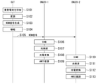
- FIG. 2 is a sequence diagram showing a processing flow of the optical access system 1 according to the first embodiment.
- the monitoring control signal application units 14-114-N included in the optical transmission units 11-1 to 11-N of the OLT 10 laser drive signals 16-1 to 16-N at the same timing synchronized by the synchronization unit 18.
- Lasers 16-1 to 16-N each output an optical signal having a wavelength corresponding to the applied drive signal.
- the modulators 17-1 to 17-N amplitude-modulate the optical signal output from the lasers 16-1 to 16-N with the input transmission data (step S102).
- the wavelength combiner 12 combines the modulated optical signals output from the respective optical transmission units 11-1 to 11-N to generate a downlink WDM signal (step S103).
- the generated downlink WDM signal is output to the optical amplifier 13.
- the optical amplifier 13 amplifies the input downlink WDM signal (step S104).
- the optical amplifier 13 outputs the amplified downlink WDM signal to the optical fiber 30.
- the downlink WDM signal output to the optical fiber 30 is branched by the optical splitter 40 and input to each ONU20-1 to 20-N.
- the downlink WDM signal input to ONU20-1 is branched by the optical turnout 21-1 (step S105).
- the downlink WDM signal branched to the first path by the optical turnout 21-1 is input to the wavelength-variable optical receiver 22-1, and the downlink WDM signal branched to the second path by the optical turnout 21-1 is received. It is input to the photoelectric converter 23-1.
- the tunable optical receiver 22-1 photodetects the input downlink WDM signal at a set wavelength (step S106).
- the photoelectric converter 23-1 converts the input downlink WDM signal into an electric signal (step S107).
- the photoelectric converter 23-1 outputs an electric signal to the AMCC demodulator 24-1.
- the AMCC demodulator 24-1 receives a monitoring control signal by demodulating the electric signal output from the photoelectric converter 23-1 (step S108).
- the downlink WDM signal input to ONU20-2 is branched by the optical turnout 21-2 (step S109).
- a part of the downlink WDM signal branched by the optical turnout 21-2 is input to the wavelength-variable optical receiver 22-2, and the other downlink WDM signal branched by the optical turnout 21-2 is the photoelectric converter 23-. It is input to 2.
- the tunable optical receiver 22-2 photodetects the input downlink WDM signal at a set wavelength (step S110).
- the photoelectric converter 23-2 converts the input downlink WDM signal into an electric signal (step S111).
- the photoelectric converter 23-2 outputs an electric signal to the AMCC demodulator 24-2.
- the AMCD demodulator 24-2 receives the monitoring control signal by demodulating the electric signal output from the photoelectric converter 23-2 (step S112).
- FIG. 3 is an explanatory diagram regarding signal performance deterioration of the monitoring control signal when the superposition ratio of the monitoring control signal to the main signal is small.
- FIG. 4 is an explanatory diagram regarding signal performance deterioration of the monitoring control signal when the superposition ratio of the monitoring control signal is large.
- the gain of EDFA is the input light intensity.
- the gain is fixed (gain clamped) by the gain for the main signal that occupies most of the signal, and the gain received by the weak signal AMCC is constant in the amplitude range, so that the signal characteristics of the monitoring control signal do not deteriorate due to the transient response.
- the gain of the EDFA changes according to the amplitude range of the monitoring control signal, and the signal characteristics of the monitoring control signal may deteriorate due to the transient response. ..
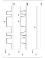
- FIG. 5 is an explanatory diagram regarding a drive current applied to the laser 16.
- FIG. 5A shows an example of the drive current 52 of the laser 16.
- amplitude-modulated baseband modulation or subcarrier modulation
- a short wave is turned on due to a change in the refractive index due to a change in the carrier density of the semiconductor.
- the wavelength changes slightly to a long wave (FIG. 5 (b)). This wavelength change causes performance deterioration of the received signal when coherently detecting the main signal.
- the signal 53 in FIG. 5B represents the wavelength shift of the thermal effect
- the signal 54 represents the wavelength shift of the carrier effect
- the signal 55 in FIG. 5C represents an oscillation wavelength shift.
- the above effect can be expected when a semiconductor laser having a structure in which heat generated by a drive current does not easily escape is used, and there are a ridge waveguide type and a high mesa waveguide type as the structure of such a semiconductor laser.
- the optical access system 1 configured as described above, it is possible to suppress deterioration of the downlink WDM signal with a simple configuration.
- the monitoring control signals are superimposed by using the lasers 16-1 to 16-N, which are indispensable components of the optical transmission units 11-1 to 11-N. High output is possible without degrading the downlink WDM signal with a simple configuration in which the optical amplifier 13 is arranged after the WDM signal is generated by the wave device 12.
- the main signal (transmission data) and the monitoring control signal are not added and are individually applied to the modulator 15 and the laser 16.
- the entire amplitude range of the electric signal that drives the modulator 15 can be assigned to the main signal. Therefore, it is possible to suppress the deterioration of the performance of the main signal.
- the time position of the monitoring control signal superimposed for each wavelength shifts at the time of reception, but the monitoring control signal is sufficiently slower than the main signal. Therefore, if the timing is adjusted by the OLT 10, it is possible to suppress the deterioration of the reception performance of the monitoring control signal due to the time position shift.
- FIG. 6 is a diagram showing a configuration example of the optical access system 1a according to the second embodiment.
- the optical access system 1a in the present invention is applicable as long as it is a system that shares at least a part of a transmission line by WDM.
- PON which is a one-to-N network, will be described as an example for simplification of the description.
- the optical access system 1a includes an OLT10a and a plurality of ONU20-1 to 20-N units.
- the OLT 10a and the ONU 20-1 to 20-N are connected via an optical fiber 30 and an optical splitter 40.
- the OLT 10a and the ONU 20-1 to 20-N communicate with each other via the optical fiber 30 and the optical splitter 40.
- the difference between the optical access system 1a and the optical access system 1 in the first embodiment is that the monitoring control signal is superimposed on the subcarrier. That is, in the optical access system 1, there are both a case where the monitoring control signal is superimposed on the subcarrier and used, and a case where the monitoring control signal is used as the baseband signal as it is, whereas the optical access system 1
- the configuration of 1a is different in that it is limited to the case where the monitoring control signal is superimposed on the subcarrier and used.
- the OLT 10a includes N optical transmission units 11a-1 to 11a-N, a wavelength combiner 12, an optical amplifier 13, and a synchronization unit 18.
- the optical transmitters 11a-1 to 11a-N generate optical signals having different wavelengths from each other.
- the optical transmission units 11a-1 to 11a-N are monitoring control signal application units 14a-1 to 14a-N, main signal generation units 15-1 to 15-N, lasers 16a-1 to 16a-N, and modulator 17 respectively. -1 to 17-N are provided.
- the OLT 10a includes monitoring control signal application units 14a-1 to 14a-N and lasers 16a-1 to 16a-N in place of the monitoring control signal application units 14-1 to 14-N and lasers 16-1 to 16-N.
- the composition is different in terms of points.
- the monitoring control signal application unit 14a-1-14a-N in the optical transmitters 11a-1 to 11a-N provided in the OLT 10a superimposes the monitoring control signal on the subcarrier and uses it. Then, the monitoring control signal application unit 14a-1-14a-N applies a drive signal in which the monitoring control signal is superimposed on the subcarrier to the lasers 16a-1 to 16a-N at the same timing synchronized by the synchronization unit 18. ..
- the monitoring control signal is subcarrier-modulated and the signal band is set to exceed the response speed of the gain of the optical amplifier 13 to avoid this, as shown in FIG. You can avoid the problem.
- a computer may be used to realize some of the functions of the OLT 10, 10a and the ONU 20 in the above-described embodiment.
- the program for realizing this function may be recorded on a computer-readable recording medium, and the program recorded on the recording medium may be read by a computer system and executed.
- the term "computer system” as used herein includes hardware such as an OS and peripheral devices.
- the "computer-readable recording medium” refers to a portable medium such as a flexible disk, a magneto-optical disk, a ROM, or a CD-ROM, and a storage device such as a hard disk built in a computer system.
- a "computer-readable recording medium” is a communication line for transmitting a program via a network such as the Internet or a communication line such as a telephone line, and dynamically holds the program for a short period of time. It may also include a program that holds a program for a certain period of time, such as a volatile memory inside a computer system that is a server or a client in that case. Further, the above program may be for realizing a part of the above-mentioned functions, and may be further realized for realizing the above-mentioned functions in combination with a program already recorded in the computer system. It may be realized by using a programmable logic device such as FPGA.
- the present invention can be applied to an optical access system using WDM.
Landscapes
- Engineering & Computer Science (AREA)
- Computer Networks & Wireless Communication (AREA)
- Signal Processing (AREA)
- Physics & Mathematics (AREA)
- Electromagnetism (AREA)
- Optics & Photonics (AREA)
- Optical Communication System (AREA)
Abstract
Description
図7は、従来の光アクセスシステム1000の構成例(その1)を示す図である。光アクセスシステム1000では、AMCC(Auxiliary Management and Control Channel)で規定される監視制御信号が波長毎に重畳されたWDM信号が上り方向及び下り方向で送受信される。
波長分波器140は、入力された光信号を各波長の光に分けて出力する。波長分波器140には、異なる波長の光を出力するための複数のポートがあり、各ポートには光受信部150-1~150-Nが接続される。
N台のコヒーレント光送信器310-1~310-Nは、主信号が重畳された各々波長の異なる光信号を生成する。これら光信号は、波長合波器320で合波されて下りWDM信号が生成される。半導体光増幅器330は、伝送路に入射するWDM信号の強度を増幅するために使用されるが、駆動電流を微弱な監視制御信号で変調してWDM信号の強度に監視制御信号を一括して重畳する。なお、ベースバンドの監視制御信号をサブキャリア変調してもよいし、非特許文献3のようにベースバンド信号のままでもよい。
(第1の実施形態)
図1は、第1の実施形態における光アクセスシステム1の構成例を示す図である。本発明における光アクセスシステム1は、WDMにより伝送路の少なくとも一部を共用するシステムであれば適用可能である。以下の説明では、光アクセスシステム1として、説明の簡略化のために1対NのネットワークであるPONを例に説明する。
主信号生成部15-1は、外部から供給された送信対象のデータを用いて主信号を生成する。
異なる波長を出力する複数のレーザ16-1~16-Nに印加される電流に重畳される監視制御信号は同一の信号である。複数の監視制御信号印加部14-1-14-Nは、互いに同期されて同じタイミングで各レーザ16-1~16-Nを駆動する。したがって、各レーザ16-1~16-Nから出力されて変調された複数の光信号が略同じタイミングで合分波器12に入力される。
同期部18は、監視制御信号印加部14-1~14-Nを同期させることによって、駆動信号の印加タイミングを同じタイミングとさせる。
OLT10の各光送信部11-1~11-Nが備える監視制御信号印加部14-1-14-Nは、同期部18により同期された同じタイミングで駆動信号をレーザ16-1~16-Nに印加する(ステップS101)。レーザ16-1~16-Nはそれぞれ、印加された駆動信号に応じた波長の光信号を出力する。変調器17-1~17-Nは、レーザ16-1~16-Nから出力された光信号を、入力された送信データで振幅変調する(ステップS102)。
ONU20-1に入力された下りWDM信号は、光分岐器21-1により分岐される(ステップS105)。光分岐器21-1で第1の経路に分岐された下りWDM信号は波長可変光受信器22-1に入力され、光分岐器21-1で第2の経路に分岐された下りWDM信号は光電変換器23-1に入力される。
図5(a)には、レーザ16の駆動電流52の一例を示す。レーザ16の駆動電流52をバイアス点を高く設定した上で微弱な監視制御信号で振幅変調(ベースバンド変調又はサブキャリア変調)すると、半導体のキャリア密度変化にともなう屈折率変化により、オン状態で短波、オフ状態で長波に波長が僅かながら変化する(図5(b))。この波長変化は、主信号をコヒーレント検波する際、受信信号の性能劣化を引き起こす。
一方、オンからオフ状態に変化すると半導体の駆動電流が減じて熱が減じることによりキャリア密度変化とは逆の屈折率変化が生じ、短波側に波長が変化する。結果的として、キャリア密度変化と熱変化による屈折率変化が相殺して、微弱信号変調による半導体レーザの波長変化を抑えることが期待できる。
図6は、第2の実施形態における光アクセスシステム1aの構成例を示す図である。本発明における光アクセスシステム1aは、WDMにより伝送路の少なくとも一部を共用するシステムであれば適用可能である。以下の説明では、光アクセスシステム1aとして、説明の簡略化のために1対NのネットワークであるPONを例に説明する。
Claims (7)
- 異なる波長の光信号を出力する複数の光送信部と、
前記複数の光送信部から出力された複数の前記光信号を波長多重する合波器と、
波長多重された光信号を増幅する増幅部と、
を備え、
前記複数の光送信部は、
監視制御信号を、レーザを駆動するための定電流に加算して駆動信号を生成して前記レーザに印加する監視制御信号印加部と、
前記監視制御信号印加部に印加された駆動信号に応じて光信号を出力するレーザと、
前記レーザから出力された光信号を、主信号で変調する変調器と、
を備える光送信装置。 - 複数の前記監視制御信号印加部は、同じタイミングで前記駆動信号を前記レーザに印加する、請求項1に記載の光送信装置。
- 前記監視制御信号印加部は、前記監視制御信号をサブキャリアに重畳して利用、又はベースバンド信号のまま利用する、請求項1又は2に記載の光送信装置。
- 前記レーザは、電流注入により発生する熱が逃げにくい導波路型の構造を有する、請求項1から3のいずれか一項に記載の光送信装置。
- 光送信装置と、光受信装置とを備える光アクセスシステムであって、
前記光送信装置は、
異なる波長の光信号を出力する複数の光送信部と、
前記複数の光送信部から出力された複数の前記光信号を波長多重する合波器と、
波長多重された光信号を増幅する増幅部と、
を備え、
前記複数の光送信部は、
監視制御信号を、レーザを駆動するための定電流に加算して駆動信号を生成して前記レーザに印加する監視制御信号印加部と、
前記監視制御信号印加部に印加された駆動信号に応じて光信号を出力するレーザと、
前記レーザから出力された光信号を、主信号で変調する変調器と、
を備え、
前記光受信装置は、
前記光信号を電気信号に変換する光電変換部と、
前記電気信号に基づいて前記監視制御信号を復調する復調部と、
を備える光アクセスシステム。 - 異なる波長の光信号を出力する複数の光送信ステップと、
前記複数の光送信部から出力された複数の前記光信号を波長多重する合波ステップと、
波長多重された光信号を増幅する増幅ステップと、
を有し、
前記複数の光送信ステップにおいて、
監視制御信号を、レーザを駆動するための定電流に加算して駆動信号を生成して前記レーザに印加する監視制御信号印加ステップと、
前記監視制御信号印加ステップにおいて印加された駆動信号に応じて光信号を出力するレーザから出力された光信号を、主信号で変調する変調ステップと、
を備える光送信方法。 - 光送信装置と、光受信装置とを備える光アクセスシステムが行う光送信方法であって、
前記光送信装置が、異なる波長の光信号を出力する複数の光送信ステップと、
前記複数の光送信部から出力された複数の前記光信号を波長多重する合波ステップと、
波長多重された光信号を増幅する増幅ステップと、
を有し、
前記複数の光送信ステップにおいて、
監視制御信号を、レーザを駆動するための定電流に加算して駆動信号を生成して前記レーザに印加する監視制御信号印加ステップと、
前記監視制御信号印加ステップにおいて印加された駆動信号に応じて光信号を出力するレーザから出力された光信号を、主信号で変調する変調ステップと、
を有し、
前記光受信装置が、
前記光信号を電気信号に変換する光電変換ステップと、
前記電気信号に基づいて前記監視制御信号を復調する復調ステップと、
を有する光送信方法。
Priority Applications (3)
| Application Number | Priority Date | Filing Date | Title |
|---|---|---|---|
| JP2022545268A JP7659363B2 (ja) | 2020-08-31 | 2020-08-31 | 光送信装置、光アクセスシステム及び光送信方法 |
| PCT/JP2020/032951 WO2022044337A1 (ja) | 2020-08-31 | 2020-08-31 | 光送信装置、光アクセスシステム及び光送信方法 |
| US18/022,914 US12445197B2 (en) | 2020-08-31 | 2020-08-31 | Optical transmitter, optical access system, and optical transmission method |
Applications Claiming Priority (1)
| Application Number | Priority Date | Filing Date | Title |
|---|---|---|---|
| PCT/JP2020/032951 WO2022044337A1 (ja) | 2020-08-31 | 2020-08-31 | 光送信装置、光アクセスシステム及び光送信方法 |
Publications (1)
| Publication Number | Publication Date |
|---|---|
| WO2022044337A1 true WO2022044337A1 (ja) | 2022-03-03 |
Family
ID=80354967
Family Applications (1)
| Application Number | Title | Priority Date | Filing Date |
|---|---|---|---|
| PCT/JP2020/032951 Ceased WO2022044337A1 (ja) | 2020-08-31 | 2020-08-31 | 光送信装置、光アクセスシステム及び光送信方法 |
Country Status (3)
| Country | Link |
|---|---|
| US (1) | US12445197B2 (ja) |
| JP (1) | JP7659363B2 (ja) |
| WO (1) | WO2022044337A1 (ja) |
Cited By (2)
| Publication number | Priority date | Publication date | Assignee | Title |
|---|---|---|---|---|
| WO2023233617A1 (ja) * | 2022-06-02 | 2023-12-07 | 日本電信電話株式会社 | 通信装置、通信システム及び通信方法 |
| JPWO2023248283A1 (ja) * | 2022-06-20 | 2023-12-28 |
Citations (5)
| Publication number | Priority date | Publication date | Assignee | Title |
|---|---|---|---|---|
| JPH10126341A (ja) * | 1996-10-21 | 1998-05-15 | Fujitsu Ltd | 光送信機及び光ネットワークシステム |
| JPH10170740A (ja) * | 1996-12-06 | 1998-06-26 | Hitachi Ltd | 導波路型光素子およびその製造方法 |
| JP2000068601A (ja) * | 1998-08-21 | 2000-03-03 | Hitachi Ltd | 利得結合分布帰還型半導体レーザ |
| JP2010011098A (ja) * | 2008-06-27 | 2010-01-14 | Fujitsu Ltd | 光伝送装置 |
| JP2010178090A (ja) * | 2009-01-29 | 2010-08-12 | Fujitsu Ltd | 光通信システムおよび光受信器 |
Family Cites Families (11)
| Publication number | Priority date | Publication date | Assignee | Title |
|---|---|---|---|---|
| JP3072047B2 (ja) * | 1995-03-22 | 2000-07-31 | 株式会社東芝 | 波長多重光伝送装置および光中継器 |
| IL121510A (en) * | 1997-08-11 | 2000-02-17 | Eci Telecom Ltd | Optical communications system |
| US6891995B2 (en) * | 2002-03-01 | 2005-05-10 | Matsushita Electric Industrial Co., Ltd. | Wavelength division multiplex transmission system |
| WO2003076979A2 (en) | 2002-03-08 | 2003-09-18 | Lightwave Electronics | Split-band depressed-profile amplifier and system |
| EP1635211B1 (en) | 2003-06-19 | 2011-08-17 | Nippon Telegraph And Telephone Corporation | Optical modulation apparatus |
| US7260332B1 (en) * | 2003-08-05 | 2007-08-21 | Broadwing Corporation | Asynchronous chirped systems, apparatuses, and methods |
| US8611747B1 (en) * | 2009-05-18 | 2013-12-17 | Cirrex Systems, Llc | Method and system for multiplexing optical communication signals |
| US8571417B2 (en) * | 2011-04-13 | 2013-10-29 | Cisco Technology, Inc. | System and method for mitigating four-wave-mixing effects |
| JP2013005216A (ja) * | 2011-06-16 | 2013-01-07 | Nec Corp | 光伝送システム及び光伝送方法 |
| US9455782B2 (en) * | 2014-08-11 | 2016-09-27 | Applied Optoelectronics, Inc. | Monitoring a multiplexed laser array in an optical communication system |
| WO2016168717A1 (en) * | 2015-04-17 | 2016-10-20 | Aurora Networks, Inc. | Sychronization of sbs suppression modulation to enable small offset, obi free, wdm signal transmission |
-
2020
- 2020-08-31 WO PCT/JP2020/032951 patent/WO2022044337A1/ja not_active Ceased
- 2020-08-31 JP JP2022545268A patent/JP7659363B2/ja active Active
- 2020-08-31 US US18/022,914 patent/US12445197B2/en active Active
Patent Citations (5)
| Publication number | Priority date | Publication date | Assignee | Title |
|---|---|---|---|---|
| JPH10126341A (ja) * | 1996-10-21 | 1998-05-15 | Fujitsu Ltd | 光送信機及び光ネットワークシステム |
| JPH10170740A (ja) * | 1996-12-06 | 1998-06-26 | Hitachi Ltd | 導波路型光素子およびその製造方法 |
| JP2000068601A (ja) * | 1998-08-21 | 2000-03-03 | Hitachi Ltd | 利得結合分布帰還型半導体レーザ |
| JP2010011098A (ja) * | 2008-06-27 | 2010-01-14 | Fujitsu Ltd | 光伝送装置 |
| JP2010178090A (ja) * | 2009-01-29 | 2010-08-12 | Fujitsu Ltd | 光通信システムおよび光受信器 |
Cited By (6)
| Publication number | Priority date | Publication date | Assignee | Title |
|---|---|---|---|---|
| WO2023233617A1 (ja) * | 2022-06-02 | 2023-12-07 | 日本電信電話株式会社 | 通信装置、通信システム及び通信方法 |
| JPWO2023233617A1 (ja) * | 2022-06-02 | 2023-12-07 | ||
| JP7795135B2 (ja) | 2022-06-02 | 2026-01-07 | Ntt株式会社 | 通信装置、通信システム及び通信方法 |
| JPWO2023248283A1 (ja) * | 2022-06-20 | 2023-12-28 | ||
| WO2023248283A1 (ja) * | 2022-06-20 | 2023-12-28 | 日本電信電話株式会社 | 光送信器、光受信器、光通信システム及び制御信号重畳方法 |
| JP7783539B2 (ja) | 2022-06-20 | 2025-12-10 | Ntt株式会社 | 光送信器、光受信器、光通信システム及び制御信号重畳方法 |
Also Published As
| Publication number | Publication date |
|---|---|
| US20230308175A1 (en) | 2023-09-28 |
| JPWO2022044337A1 (ja) | 2022-03-03 |
| US12445197B2 (en) | 2025-10-14 |
| JP7659363B2 (ja) | 2025-04-09 |
Similar Documents
| Publication | Publication Date | Title |
|---|---|---|
| US8131156B2 (en) | Centralized lightwave WDM-PON employing intensity modulated downstream and upstream | |
| CN102187604B (zh) | 光网络中的调制的改进或者与光网络中的调制相关的改进 | |
| US8055133B2 (en) | TDM/WDMA passive optical network device | |
| EP2157722B1 (en) | WDM PON RF overlay architecture based on quantum dot multi-wavelength laser source | |
| US7965947B2 (en) | Wavelength division multiplexing passive optical network architecture with source-free optical network units | |
| US8571419B2 (en) | Method and system for flexible optical signal aggregation and transmission | |
| Duong et al. | Experimental demonstration of 10 Gbit/s upstream transmission by remote modulation of 1 GHz RSOA using adaptively modulated optical OFDM for WDM-PON single fiber architecture | |
| EP2617144B1 (en) | Passive optical networks | |
| JP2014527740A (ja) | 光アクセスネットワーク | |
| Yu et al. | Demonstration of a novel WDM passive optical network architecture with source-free optical network units | |
| JP7659363B2 (ja) | 光送信装置、光アクセスシステム及び光送信方法 | |
| Calabretta et al. | A bidirectional WDM/TDM-PON using DPSK downstream signals and a narrowband AWG | |
| US20040208634A1 (en) | Optical signal multiplexer/demultiplexer employing pseudorandom mode modulation | |
| Karlık | Quadruple impact of SPM, XPM, FWM and SRS nonlinear impairments on the performance of DWDM-PON | |
| JP7473841B2 (ja) | 光アクセスシステム、光受信装置及び復調方法 | |
| Huang et al. | A novel symmetric lightwave centralized WDM-OFDM-PON architecture with OFDM-remodulated ONUs and a coherent receiver OLT | |
| Ibrahim et al. | Demonstration of CoWDM using DPSK modulator array with injection-locked lasers | |
| Mun et al. | DAPSK-OFDM-based coherent PON and IFoF heterogeneous access network with PDM | |
| Chen et al. | Bidirectional mobile fronthaul based on wavelength reused MDM | |
| Schrenk et al. | Rayleigh scattering tolerant PON assisted by four-wave mixing in SOA-based ONUs | |
| Zhang et al. | Bidirectional 40 Gb/s/λ, 100 km-reach, channel-reuse WDM-PON employing tunable optical transceiver with optical intensity detection-based wavelength management | |
| Huang et al. | A simple WDM-PON architecture to simultaneously provide triple-play services by using one single modulator | |
| Chen et al. | A scalable metro-access integrated network system with reconfigurable WDM central ring and high-quality OFDMA access trees | |
| Le et al. | TDM/DWDM PON extender for 10 Gbit/s downstream transmission | |
| Thollabandi et al. | Colorless flexi-grid WDM-PON system based on polarization multiplexed optical comb |
Legal Events
| Date | Code | Title | Description |
|---|---|---|---|
| 121 | Ep: the epo has been informed by wipo that ep was designated in this application |
Ref document number: 20951586 Country of ref document: EP Kind code of ref document: A1 |
|
| ENP | Entry into the national phase |
Ref document number: 2022545268 Country of ref document: JP Kind code of ref document: A |
|
| NENP | Non-entry into the national phase |
Ref country code: DE |
|
| 122 | Ep: pct application non-entry in european phase |
Ref document number: 20951586 Country of ref document: EP Kind code of ref document: A1 |
|
| WWG | Wipo information: grant in national office |
Ref document number: 18022914 Country of ref document: US |