WO2022044320A1 - Substrate work machine - Google Patents
Substrate work machine Download PDFInfo
- Publication number
- WO2022044320A1 WO2022044320A1 PCT/JP2020/032869 JP2020032869W WO2022044320A1 WO 2022044320 A1 WO2022044320 A1 WO 2022044320A1 JP 2020032869 W JP2020032869 W JP 2020032869W WO 2022044320 A1 WO2022044320 A1 WO 2022044320A1
- Authority
- WO
- WIPO (PCT)
- Prior art keywords
- safety
- control circuit
- input
- execution unit
- work execution
- Prior art date
Links
Images


Classifications
-
- H—ELECTRICITY
- H05—ELECTRIC TECHNIQUES NOT OTHERWISE PROVIDED FOR
- H05K—PRINTED CIRCUITS; CASINGS OR CONSTRUCTIONAL DETAILS OF ELECTRIC APPARATUS; MANUFACTURE OF ASSEMBLAGES OF ELECTRICAL COMPONENTS
- H05K13/00—Apparatus or processes specially adapted for manufacturing or adjusting assemblages of electric components
Definitions
- This specification relates to a board-to-board working machine that performs predetermined work on a board.
- the safety management device disclosed in Patent Document 1 includes multiple safety function units on one processor, and determines the normality / abnormality of each safety function unit. According to the description of the embodiment, the diagnostic processing unit of the safety function unit is duplicated, the other diagnostic processing unit is operated when an abnormality of one diagnostic processing unit is determined, and the abnormality of the other diagnostic processing unit is further detected. If it is determined, the CPU (processor) is reset. As a result, even if a part of the safety function becomes abnormal, other normal safety functions can be continuously performed.
- control digital controller of Patent Document 2 performs a means for performing a self-diagnosis, a means for storing a serious error detected by the self-diagnosis, and a retry of the self-diagnosis for a detected minor error.
- a means, a means for storing the number of retries, and a means for determining the seriousness of the error from the number of retries are provided. According to this, it is said that the maintainability can be improved by storing a serious error, and the usability can be improved by retrying a minor error.
- Patent Document 1 As a countermeasure against these problems, a configuration in which the multiplexing technology of Patent Document 1 is applied to a safety control circuit cannot be adopted because it causes a significant cost increase. Further, even if the self-diagnosis function of Patent Document 2 is added to the safety control circuit, the defect itself due to the influence of disturbance cannot be eliminated.
- This specification describes a work execution unit that operates by receiving power from a power source to perform predetermined work on a board, a safety monitoring unit that outputs a safety detection signal when the safety of the machine is ensured, and a start signal. It is started by input, and when the safety detection signal is input, the power supply is supplied to the work execution unit, and when the safety detection signal is not input, the power supply is not supplied to the work execution unit. When the safety control circuit and the power supply are not supplied to the work execution unit even if the first start signal is input to the safety control circuit, the second start signal is input to the safety control circuit again.
- an anti-board working machine including a restart control unit for starting.
- the restart control unit safely secures the second start signal. Input to the control circuit and restart. Therefore, the safety control circuit can be restarted automatically. Then, in many cases of restart due to the influence of the disturbance, the safety control circuit operates well, the power supply is supplied to the work execution unit, and the board work machine starts operating normally. As a result, the delay in starting the operation of the board-to-board working machine is suppressed, and in addition, the trouble of restarting by the operator becomes unnecessary.
- FIG. 1 It is a perspective view which shows the whole structure of the component mounting machine which is an example of the board-to-board work machine of an embodiment. It is a figure explaining the structure about the safety assurance of a component mounting machine, and is the figure which included a functional block and a control circuit. It is a figure of the time chart explaining the normal operation about the safety assurance at the start of operation of a component mounting machine. It is a figure of the time chart explaining the operation when the restart for safety assurance is performed at the time of starting the operation of a component mounting machine. It is a figure explaining the modification of the configuration regarding the safety assurance of a component mounting machine.
- the component mounting machine 1 (board-to-board working machine of the embodiment)
- the overall configuration of the component-mounting machine 1 which is an example of the board-to-board working machine of the embodiment will be described with reference to FIG.
- the direction from the upper left to the lower right of FIG. 1 is the X-axis direction for transporting the substrate K, and the direction from the upper right to the lower left is the Y-axis direction which is the front-rear direction of the component mounting machine 1.
- the component mounting machine 1 repeatedly carries out the component mounting work.
- the component mounting machine 1 includes a board transfer device 2, a component supply device 3, a component transfer device 4, a component camera 5, a control device 6 (see FIG. 2), a base 10, and the like.
- the board transfer device 2 is composed of a first guide rail 21, a second guide rail 22, a pair of conveyor belts, a clamp device 23, and the like.
- the first guide rail 21 and the second guide rail 22 extend in the X-axis direction across the upper center of the base 10, and are assembled to the base 10 so as to be parallel to each other.
- a pair of conveyor belts arranged in parallel with each other separated from each other are arranged side by side.
- the pair of conveyor belts rotate around with the substrate K placed on the conveyor transport surface, and carry in and out the substrate K to the mounting implementation position set in the central portion of the base 10.
- a clamp device 23 is provided below the mounting position. The clamping device 23 pushes up the substrate K, clamps it in a horizontal posture, and positions it at the mounting implementation position.
- the parts supply device 3 is detachably mounted on the rear side of the parts mounting machine 1.
- the component supply device 3 is configured by arranging a plurality of feeder devices 31 in a row on the device pallet 35.
- the feeder device 31 includes a main body 32, a supply reel 33 provided on the rear side of the main body 32, and a component take-out portion 34 provided on the upper part of the front end of the main body 32.
- a carrier tape in which a large number of parts are enclosed at a predetermined pitch is wound and held on the supply reel 33. When the carrier tape is sent out at a predetermined pitch, the parts are released from the sealed state and are sequentially sent to the part take-out unit 34.
- the component transfer device 4 is composed of a pair of Y-axis rails 41, a Y-axis moving table 42, a Y-axis motor 43, an X-axis moving table 44, an X-axis motor 45, a mounting head 46, and the like.
- the pair of Y-axis rails 41 are provided from the front portion of the base 10 to the upper portion of the component supply device 3 at the rear portion.
- the Y-axis moving table 42 is loaded on a pair of Y-axis rails 41.
- the Y-axis moving table 42 is driven from the Y-axis motor 43 via a ball screw mechanism and moves in the Y-axis direction.
- the X-axis moving table 44 is loaded on the Y-axis moving table 42.
- the X-axis moving table 44 is driven from the X-axis motor 45 via a ball screw mechanism and moves in the X-axis direction.
- the mounting head 46 is arranged on the rear side of the X-axis moving table 44.
- the mounting head 46 has a rotary tool 47 on the lower side.
- a plurality of suction nozzles are arranged in an annular shape under the rotary tool 47.
- the suction nozzle set at the operating position is driven by the Z-axis motor 48 to move up and down.
- the suction nozzle sucks the component from the component take-out unit 34 by supplying a negative pressure, and mounts the component on the substrate K by supplying a positive pressure.
- a pinching chuck for sandwiching the component may be used.
- the board camera 49 is provided under the X-axis moving table 44 and is arranged side by side with the mounting head 46.
- the board camera 49 captures a position mark attached to the positioned board K.
- the image data acquired by the imaging is image-processed, and the accurate mounting position of the substrate K is detected.
- the component camera 5 is provided upward on the upper surface of the base 10 between the board transfer device 2 and the component supply device 3.
- the component camera 5 photographs a state in which a plurality of suction nozzles of the mounting head 46 are sucking the component by the component extraction unit 34 and moving to the substrate K.
- the component camera 5 can collectively image the components held by the plurality of suction nozzles.
- the acquired image data is image-processed to confirm the adsorption state of the component, the vertical and horizontal dimensions of the component, the electrode arrangement, and the like.
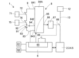
- the board transfer device 2, the parts supply device 3, the parts transfer device 4, and the parts camera 5 correspond to a work execution unit that operates by receiving power from a power source and performs a predetermined work on the board K. Since the work execution unit has a movable portion, a protective cover 11 is provided to ensure the safety inside the component mounting machine 1.
- the protective cover 11 is opened and closed by an operator. With the protective cover 11 open, the operator can visually check the inside of the machine, the state of the board K, and the like. Safety is not ensured when the protective cover 11 is open, and the supply of power to the work execution unit (board transfer device 2, parts supply device 3, parts transfer device 4, and parts camera 5) is safety controlled. It is stopped by the circuit 8 (described later).
- the control device 6 (see FIG. 2) holds job data for each type of the substrate K and controls the mounting work.
- Job data is data that describes detailed procedures and methods for mounting work.
- the control device 6 controls by transmitting various commands to the work execution unit (board transfer device 2, component supply device 3, component transfer device 4, and component camera 5). Further, the control device 6 receives information on the operation status and the like from the work execution unit.
- the control device 6 may be configured by a single computer device, or may be configured by distributing the functions to a plurality of computer devices.
- control device 6 includes an input unit 61 and a display unit 62 as a man-machine interface.
- the operator inputs a command to start operation using the input unit 61.
- the control device 6 that has received the operation start command performs the initial processing by utilizing the control power supply of the work execution unit.
- Initial processing includes confirmation of the initial position of the moving part, transition from the hibernation state of the moving part to the standby state, and calibration of various sensors.
- the control device 6 appropriately displays the content of the operator's command, the progress status of the initial processing, the operating status during operation, and the like on the display unit 62.
- the configuration related to ensuring safety includes a safety monitoring unit, a safety control circuit 8, and a restart control unit 65.
- the safety monitoring unit is a part that monitors the safety inside the parts mounting machine 1, and outputs a safety detection signal when the safety inside the machine is ensured.
- the safety monitoring unit outputs a safety detection signal for each of the plurality of safety-related monitoring items, and specifically includes a cover switch 71 and an emergency stop button 75.
- the cover switch 71 is a switch that monitors the open / closed state of the protective cover 11.
- the cover switch 71 has an output contact 72 for outputting a safety detection signal.
- the output contact 72 has a specification of b-contact that conducts in a normal state when the protective cover 11 is closed and safety is ensured, and is shut off when the protective cover 11 is opened and safety is not ensured. That is, the output contact 72 conducts or is cut off depending on whether or not the cover switch 71 outputs a safety detection signal.
- the emergency stop button 75 is omitted in FIG. 1, it is provided at a position where the side surface of the base 10 can be easily operated.
- the emergency stop button 75 is a button pressed by an operator who determines that safety is not ensured.
- the emergency stop button 75 functions regardless of the state of the cover switch 71.
- the emergency stop button 75 has an output contact 76 for outputting a safety detection signal.
- the output contact 76 is a b-contact specification with a cutoff holding function that conducts in a normal time when the emergency stop button 75 is not pressed and holds a cutoff state in an emergency when the emergency stop button 75 is pressed.
- the history of pressing the emergency stop button 75 in other words, the cutoff state of the output contact 76 is released by pressing the emergency release button in the figure, and returns to the conduction state.
- the output contact 76 conducts or is cut off depending on the presence or absence of the safety detection signal that the emergency stop button 75 is not pressed and that the emergency stop button 75 has a history of pressing.
- the safety monitoring unit only one of the cover switch 71 and the emergency stop button 75 may be used, or three or more parts may be used. Further, as the safety monitoring unit, a part other than the above, for example, a human sensing sensor or an image monitoring device for monitoring the excessive approach of the operator may be used. Further, as the safety detection signal of the safety monitoring unit, a signal other than the b contact, for example, an analog voltage signal or a communication signal may be used.
- the safety control circuit 8 is started by inputting a start signal.
- the safety control circuit 8 supplies power to the work execution unit (board transfer device 2, parts supply device 3, parts transfer device 4, and parts camera 5) to detect safety. Do not supply power to the work execution unit when no signal is input. Strictly speaking, the safety control circuit 8 supplies power to the work execution unit only when all the safety detection signals of the plurality of monitoring items are input and the operation preparation signal (described later) is input. Power.
- the safety control circuit 8 is composed of a safety input circuit 81, an operation preparation input circuit 82, a main body circuit 84, a safety output relay 87, and the like.
- the safety input circuit 81 is configured by connecting the output contact 72 of the cover switch 71 and the output contact 76 of the emergency stop button 75 in series. Both ends of the safety input circuit 81 are connected to the main body circuit 84.
- the operation preparation input circuit 82 is composed of an operation preparation contact 83, and both ends thereof are connected to the main body circuit 84.
- the operation preparation contact 83 transitions from the cutoff state to the conduction state by the operation preparation signal from the restart control unit 65.
- the main body circuit 84 is composed of a sequence circuit, a programmable controller, and the like, and operates according to a predetermined logic sequence.
- the main body circuit 84 can confirm that the safety detection signals of all the monitoring items are input by the continuity state of the safety input circuit 81. Further, the main body circuit 84 can confirm that the operation preparation signal is input by the continuity state of the operation preparation input circuit 82.
- the main body circuit 84 has a command input terminal 85 that receives an operation command.
- the main body circuit 84 recognizes the rising edge of the operation command input to the command input terminal 85 as a start signal, and performs a predetermined start process. Specifically, the main body circuit 84 confirms that the operation command has continued for a minute time after the rise of the operation command, or that the operation command is still input after a minute time has elapsed from the rise of the operation command. After confirming, start the start process. Further, the main body circuit 84 continuously carries out the safety monitoring process during operation while the operation command is input to the command input terminal 85 after the start process is completed. The details of the start processing and the safety monitoring processing will be described later.
- the main body circuit 84 controls the excitation of the safety output relay 87 from the output terminal 86.
- the safety output relay 87 has a main contact 88 and an auxiliary contact 89.
- the main contact 88 is inserted in the middle of the power supply line 13 that connects the power supply device 12 and the work execution unit (board transfer device 2, component supply device 3, component transfer device 4, and component camera 5).
- the main contact 88 a contact is used from the viewpoint of fail-safe, and a contact capacity (maximum voltage, maximum current) commensurate with the work execution unit is secured.
- the power supply device 12 supplies power to the work execution unit.
- As the power source a specified DC voltage, an AC voltage of a commercial frequency, or the like can be exemplified.
- the main body circuit 84 excites the safety output relay 87 and powers the work execution unit from the power supply device 12 only when the continuity state of the safety input circuit 81 and the continuity state of the operation preparation input circuit 82 are confirmed in the starting process. Supply power.
- the auxiliary contact 89 is a contact that synchronizes with the state change of the main contact 88, and in the present embodiment, the same a contact as the main contact 88 is used. Further, the contact capacity of the auxiliary contact 89 may be smaller than that of the main contact 88.
- the auxiliary contact 89 is not limited to this, and may be a b contact. Further, a c-contact in which the main contact 88 and the auxiliary contact 89 are integrated may be used. The state of the auxiliary contact 89 is input to the restart control unit 65.
- the restart control unit 65 is realized by the software of the control device 6.
- the restart control unit 65 is integrally provided with the control device 6 that controls the work execution unit (board transfer device 2, component supply device 3, component transfer device 4, and component camera 5).
- the restart control unit 65 After receiving the operator's operation start command, the restart control unit 65 inputs an operation command to the command input terminal 85 of the main body circuit 84 of the safety control circuit 8. The rise of this operation command becomes the above-mentioned start signal. Therefore, the restart control unit 65 also serves as an initial start control unit that inputs the initial start signal to the safety control circuit 8.
- restart control unit 65 safely controls the second start signal when the power supply is not supplied to the work execution unit even after a predetermined time has elapsed since the first start signal was input to the safety control circuit 8. Input to circuit 8. Further, the restart control unit 65 warns of an error stop when the power supply is not supplied to the work execution unit even if the second start signal is input to the safety control circuit 8 (details will be described later).
- the restart control unit 65 determines whether or not power is being supplied to the work execution unit by acquiring the state of the main contact 88 based on the state of the auxiliary contact 89. Further, the restart control unit 65 outputs an operation preparation signal indicating that the initial processing related to the work execution unit is normally completed and the operation preparation is completed to the safety control circuit 8. In other words, the restart control unit 65 closes the operation preparation contact 83 and conducts the operation preparation input circuit 82 when the initial processing related to the work execution unit is normally completed.
- FIG. 3 shows a normal operation for ensuring safety.
- FIG. 4 shows a case where the restart for ensuring safety is performed, and the operation is the same as that of FIG. 3 before the time t4.
- the upper graph of FIGS. 3 and 4 shows the operation command input from the restart control unit 65 to the command input terminal 85, and the middle graph shows the operation preparation signal (state of the operation preparation contact 83), and the lower graph shows.
- the graph of is shown the state of the main contact 88 and the auxiliary contact 89 of the safety output relay 87.
- the time axis t in FIGS. 3 and 4 is scaled out (not necessarily equidistant scales).
- the control device 6 Before the time t1 in FIG. 3, the control device 6 has received the command to start the operation of the operator.
- the restart control unit 65 inputs an operation command to the command input terminal 85.
- an operation command is a signal that continues at a high level.
- the main body circuit 84 confirms that the high level has continued for a minute time ⁇ T after the operation command has been raised, and recognizes it as the start signal SS.
- the main body circuit 84 confirms that the operation command is still input (high level) after a minute time ⁇ T has elapsed from the rise of the operation command, and recognizes it as the start signal SS.
- the main circuit 84 starts the start process after recognizing the start signal SS.
- the main body circuit 84 can accurately recognize the start signal SS even if the rise of the operation command is unstable.
- the main body circuit 84 does not erroneously recognize the intrusion of pulsed noise having a short duration as the start signal SS. Therefore, the main body circuit 84 has high reliability in recognizing the start signal SS, and does not accidentally start the start process.
- the restart control unit 65 outputs an operation preparation signal for the second predetermined time T2 to close the operation preparation contact 83.
- the continuity state of the operation preparation input circuit 82 is continued until the time t3 after the second predetermined time T2 has elapsed.
- the first predetermined time T1, the second predetermined time T2, and the third predetermined time T3 described later are timed and controlled by the restart control unit 65, and the time specified in the logic sequence of the main circuit 84. It is set appropriately based on the length of the circuit and the transient characteristics that depend on the circuit configuration.
- the main body circuit 84 confirms whether or not the safety input circuit 81 and the operation preparation input circuit 82 are in a conductive state. Normally, both the safety input circuit 81 and the operation preparation input circuit 82 are in a conductive state. In this case, the main body circuit 84 starts exciting the safety output relay 87 at a time t4 after the time t3, and maintains the excited state thereafter. Therefore, at approximately time t4, the main contact 88 transitions from the cutoff state to the conduction state, and power is supplied from the power supply device 12 to the work execution unit.
- the restart control unit 65 confirms the state of the auxiliary contact 89. Normally, the auxiliary contact 89 is in a conductive state. As a result, the restart control unit 65 can confirm that the start process has been completed normally.
- the main circuit 84 ends the start processing at the time t4, and shifts to the safety monitoring processing during operation.
- the main body circuit 84 continues to excite the safety output relay 87 while the and condition that the operation command is input and the safety input circuit 81 is in the conduction state is satisfied. Further, when the and condition is not satisfied, the main body circuit 84 cuts off the excitation of the safety output relay 87 and stops the power supply to the work execution unit.
- the operation preparation input circuit 82 is not used in the safety monitoring process.
- the time t5 is the time when a predetermined time (the sum of the first predetermined time T1, the second predetermined time T2, and the third predetermined time T3) has elapsed since the first start signal SS was input to the safety control circuit 8. Equivalent to. In this defect, it is presumed that the safety output relay 87 is not excited at time t4 and the power supply is not supplied to the work execution unit. The following 1) to 4) can be considered as the cause of this problem.
- Non-conducting state of the safety input circuit 81 Specifically, it occurs when the protective cover 11 is open or there is a history of pressing the emergency stop button 75. In order to eliminate this non-conducting state, it is necessary to return the protective cover 11 to the closed state and press the emergency release button to release the pressing history of the emergency stop button 75.
- Non-conducting state of the operation preparation input circuit 82 Specifically, it occurs when the restart control unit 65 does not output the operation preparation signal. In order to eliminate this non-conducting state, it is necessary to normally end the initial processing related to the work execution unit and output the operation preparation signal to the restart control unit 65.
- Temporary malfunction of the safety control circuit 8 due to the influence of disturbance The disturbance may be transient electrical noise invading from outside the machine or destabilization of the contact state due to accidental vibration. The frequency of occurrence is higher than that of the following 4). By restarting the safety control circuit 8, there is a great possibility that the temporary malfunction can be resolved.
- Failure of the safety control circuit 8 Specifically, it is a failure of the main body circuit 84, the safety output relay 87, contacts, etc., and occurs very rarely. Automatic repair is almost difficult. If the safety control circuit 8 is repeatedly restarted unnecessarily, the failure damage may increase or the failure range may increase.
- the cause is that the restart control unit 65 does not output the operation preparation signal by itself, so the restart control is not performed. Instead, the restart control unit 65 displays on the display unit 62 that the initial processing related to the work execution unit has not been completed normally, and requests the operator to take action.
- the restart control unit 65 controls the restart without specifying the cause. More specifically, at the time t6 after the time t5 in FIG. 4, the restart control unit 65 temporarily cancels the operation command (falls down to the low level). Then, at the time t11 after the time t6, the restart control unit 65 re-inputs the operation command to the command input terminal 85. This input process corresponds to the process of inputting the second start signal SS to the safety control circuit 8.
- the main body circuit 84 recognizes the second rise as the start signal SS in the same manner as the first rise of the operation command, and starts the restart process.
- the restart processing content performed between the time t11 and the time t15 in FIG. 4 is the same as the processing content of the start processing from the time t1 to the time t5.
- the safety output relay 87 is excited at time t14 in FIG. 4, and the continuity state of the auxiliary contact 89 is often confirmed at time t15. In this case, since the component mounting machine 1 can start operation, the delay in starting operation is suppressed. In addition, there is no need for the operator to restart.
- the restart control unit 65 displays an error stop warning on the display unit 62 and waits for the operator to take action.
- an error stop warning may be notified by a means or method other than the display unit 62, for example, transmission to a mobile terminal carried by the operator.
- the operator who confirmed the warning investigates whether the safety of the component mounting machine 1 is ensured and takes measures. Specifically, the operator confirms the closed state of the protective cover 11 and presses the emergency release button just in case. If the cause of the problem is 1) above, the safety control circuit 8 can normally end the start processing according to the subsequent command to start the operation of the operator.
- the restart control unit 65 does not restart a plurality of times. That is, the safety control circuit 8 does not repeat the restart process regardless of whether or not it is out of order. Therefore, even if the safety control circuit 8 is out of order, there is no possibility that the failure damage will be large or the failure range will be expanded.
- the work execution unit (board transfer device 2, component supply device 3, component) is transmitted from the power supply device 12.
- the restart control unit 65 inputs the second start signal SS to the safety control circuit 8 to restart. Therefore, the safety control circuit 8 can be automatically restarted. Then, in many cases of restart due to the influence of the disturbance, the safety control circuit 8 operates well, the power supply is supplied to the work execution unit, and the component mounting machine 1 starts operating normally. As a result, the delay in starting the operation of the component mounting machine 1 is suppressed, and in addition, the trouble of restarting by the operator becomes unnecessary.
- the comprehensive input circuit 9 is input to the main body circuit 84A instead of the safety input circuit 81 and the operation preparation input circuit 82, and the other configurations are not modified.
- the comprehensive input circuit 9 includes an output contact 72 of the cover switch 71, an output contact 76 of the emergency stop button 75, an operation preparation contact 83, and a changeover switch 91.
- the main body circuit 84A has a first input terminal 841, a second input terminal 842, and a third input terminal 843.
- the changeover switch 91 has a main terminal 92, a start terminal 93, and an operation terminal 94.
- An output contact 72 and an output contact 76 are connected in series between the first input terminal 841 and the main terminal 92.
- the second input terminal 842 is connected to the operating terminal 94.
- An operation preparation contact 83 is connected between the third input terminal 843 and the starting terminal 93.
- the changeover switch 91 is controlled from the main body circuit 84A.
- the changeover switch 91 connects the main terminal 92 and the start terminal 93 in the initial state of the start process (connection of the solid line in FIG. 5), and connects the main terminal 92 and the operation terminal 94 in the safety monitoring process during operation (the connection of the solid line in FIG. 5). Connection of broken lines in FIG. 5).
- the same operation as that of the embodiment shown in FIGS. 3 and 4 is performed. That is, when the main body circuit 84A recognizes the start signal SS, the start process is started (time t1), and it is confirmed whether or not there is a conduction state between the first input terminal 841 and the third input terminal 843 (time t2). ⁇ Time t3). If it is in a conducting state, the main body circuit 84A starts exciting the safety output relay 87 (time t4).
- the main body circuit 84A connects the main terminal 92 of the changeover switch 91 and the operating terminal 94.
- the main body circuit 84A shifts from the start processing to the safety monitoring processing during operation, and monitors the continuity state between the first input terminal 841 and the second input terminal 842 (after time t4). Then, when the space between the first input terminal 841 and the second input terminal 842 is cut off, the main body circuit 84A cuts off the excitation of the safety output relay 87 and stops the power supply to the work execution unit.
- the restart control unit 65 controls the restart without specifying the cause (time t6 or later).
- the restart process is started with the main terminal 92 of the changeover switch 91 and the start-up terminal 93 connected to each other.
- the safety control circuit 8 can be automatically restarted. Therefore, as in the embodiment, the delay in starting the operation of the component mounting machine 1 is suppressed, and in addition, the trouble of restarting by the operator becomes unnecessary.
- the start signal SS may be a signal having a form other than the rise of the operation command, for example, a rectangular wave signal having a predetermined time width. Further, the operation preparation input circuit 82 and the operation preparation contact 83 can be omitted. Further, the method of recognizing the start signal SS by confirming the continuation of the high level of the minute time ⁇ T at the rise of the operation command can be applied to the state confirmation of the operation preparation contact 83 and the auxiliary contact 89. This improves the noise resistance and reliability of status confirmation. Further, the initial start control unit for inputting the initial start signal SS to the safety control circuit 8 may be provided separately from the restart control unit 65.
- the restart control unit 65 may determine whether or not the power supply is supplied to the work execution unit based on the information other than the auxiliary contact 89.
- a charge detection sensor for detecting the charge state may be provided on the load side of the main contact 88 of the power supply line 13, and the detection signal may be input to the restart control unit 65.
- the configuration for ensuring the safety of the embodiment and the modified example is applied to other types of anti-board work machines having different work implementation units (board transfer device 2, parts supply device 3, parts transfer device 4, and parts camera 5). Can be applied.
- the embodiments and modifications can be applied and modified in various other ways.
Abstract
A substrate work machine according to the present invention comprises: a work implementation unit that operates by receiving electricity from a dynamic power supply, and that implements prescribed work on a substrate; a safety monitoring unit that outputs a safety detection signal when safety inside the machine has been ensured; a safety control circuit that activates via input of a startup signal, provides the dynamic power supply to the work implementation unit when the safety detection signal has been inputted, and does not supply the dynamic power supply to the work implementation unit when the safety detection signal has not been inputted; and a restart control unit that causes a restart to occur, upon a second occurrence of a startup signal being inputted to the safety control circuit, if the dynamic power supply is not provided to the work implementation unit even though an initial occurrence of the startup signal has been inputted to the safety control circuit.
Description
本明細書は、基板に対して所定の作業を実施する対基板作業機に関する。
This specification relates to a board-to-board working machine that performs predetermined work on a board.
プリント配線が施された基板に対基板作業を実施して、基板製品を量産する技術が普及している。さらに、複数種類の対基板作業機を並べて配置することにより、対基板作業ラインを構成することが一般的になっている。多くの対基板作業機には、機内の安全を確保するための安全制御回路が設けられている。安全制御回路は、安全が確保されていない場合に、動力電源の給電を停止して稼働を中断し、あるいは稼働を開始させない。この種の安全制御回路に関する技術例が特許文献1、2に開示されている。
The technology of mass-producing board products by carrying out board-to-board work on boards with printed wiring is widespread. Further, it is common to configure a board-to-board work line by arranging a plurality of types of board-to-board work machines side by side. Many anti-board work machines are provided with a safety control circuit to ensure the safety inside the machine. When safety is not ensured, the safety control circuit stops the power supply of the power source to interrupt the operation or does not start the operation. Technical examples of this type of safety control circuit are disclosed in Patent Documents 1 and 2.
特許文献1に開示された安全管理装置は、1つのプロセッサ上に多重化された安全機能部を備え、各安全機能部の正常/異常を判定する。実施形態の説明によれば、安全機能部の診断処理部を二重化し、一方の診断処理部の異常が判定された場合に他方の診断処理部を稼働させ、さらに他方の診断処理部の異常が判定された場合に、CPU(プロセッサ)をリセットする。これにより、安全機能の一部に異常が生じた場合でも他の正常な安全機能を継続して実施できる、とされている。
The safety management device disclosed in Patent Document 1 includes multiple safety function units on one processor, and determines the normality / abnormality of each safety function unit. According to the description of the embodiment, the diagnostic processing unit of the safety function unit is duplicated, the other diagnostic processing unit is operated when an abnormality of one diagnostic processing unit is determined, and the abnormality of the other diagnostic processing unit is further detected. If it is determined, the CPU (processor) is reset. As a result, even if a part of the safety function becomes abnormal, other normal safety functions can be continuously performed.
また、特許文献2の制御用ディジタルコントローラは、自己診断を行う手段と、自己診断により検出された重大なエラーを記憶する手段と、検出された軽微なエラーに対して自己診断の再試行を行う手段と、再試行回数を記憶する手段と、再試行回数からエラーの重大性を判断する手段と、を備える。これによれば、重大なエラーを記憶することにより保守可能性を向上できると共に、軽微なエラーについて再試行を行うことにより使用可能性を向上できる、とされている。
Further, the control digital controller of Patent Document 2 performs a means for performing a self-diagnosis, a means for storing a serious error detected by the self-diagnosis, and a retry of the self-diagnosis for a detected minor error. A means, a means for storing the number of retries, and a means for determining the seriousness of the error from the number of retries are provided. According to this, it is said that the maintainability can be improved by storing a serious error, and the usability can be improved by retrying a minor error.
ところで、対基板作業機の稼働開始に際して安全制御回路を始動させたときに、安全が確保されていなければ、当然ながら動力電源は給電されない。しかしながら、安全が確保されているにも関わらず、動力電源が給電されない不具合が生じ得る。この不具合の原因として、安全制御回路の故障、および外乱の影響が考えられる。前者の場合、対基板作業機の稼働は困難であり、対処作業が必要であるが、極く稀にしか発生しない。後者の場合、対処作業は必要でなく、安全制御回路を再始動してやれば、対基板作業機が正常に稼働することが多い。従来、安全制御回路の再始動は、オペレータの手動操作によって行われていた。このため、対基板作業機の稼働開始が遅延し、さらには手動操作の手間がかかるという問題点が発生していた。
By the way, when the safety control circuit is started at the start of operation of the anti-board work machine, if safety is not ensured, the power supply will not be supplied as a matter of course. However, even though safety is ensured, there may be a problem that the power supply is not supplied. The cause of this failure is considered to be the failure of the safety control circuit and the influence of disturbance. In the former case, it is difficult to operate the board-to-board work machine, and countermeasure work is required, but it occurs very rarely. In the latter case, no coping work is required, and if the safety control circuit is restarted, the board-to-board work machine often operates normally. Conventionally, the restart of the safety control circuit has been performed manually by the operator. For this reason, there has been a problem that the start of operation of the board-to-board work machine is delayed, and further, it takes time and effort for manual operation.
これらの問題点の対策として、特許文献1の多重化の技術を安全制御回路に適用した構成は、大幅なコスト増加を招くため、採用することができない。また、安全制御回路に特許文献2の自己診断機能を付与しても、外乱の影響による不具合そのものを無くすことはできない。
As a countermeasure against these problems, a configuration in which the multiplexing technology of Patent Document 1 is applied to a safety control circuit cannot be adopted because it causes a significant cost increase. Further, even if the self-diagnosis function of Patent Document 2 is added to the safety control circuit, the defect itself due to the influence of disturbance cannot be eliminated.
それゆえ、本明細書では、安全制御回路を始動しても動力電源が給電されない場合に、安全制御回路を自動で再始動することができる対基板作業機を提供することを解決すべき課題とする。
Therefore, in the present specification, it is a problem to be solved to provide an anti-board working machine capable of automatically restarting the safety control circuit when the power supply is not supplied even if the safety control circuit is started. do.
本明細書は、動力電源の受電によって動作し、基板に所定の作業を実施する作業実施部と、機内の安全が確保されているときに安全検出信号を出力する安全監視部と、始動信号の入力によって始動し、前記安全検出信号が入力されている場合に前記作業実施部に前記動力電源を給電し、前記安全検出信号が入力されていない場合に前記作業実施部に前記動力電源を給電しない安全制御回路と、初回の前記始動信号が前記安全制御回路に入力されても前記作業実施部に前記動力電源が給電されない場合に、二回目の前記始動信号を前記安全制御回路に入力して再始動させる再始動制御部と、を備える対基板作業機を開示する。
This specification describes a work execution unit that operates by receiving power from a power source to perform predetermined work on a board, a safety monitoring unit that outputs a safety detection signal when the safety of the machine is ensured, and a start signal. It is started by input, and when the safety detection signal is input, the power supply is supplied to the work execution unit, and when the safety detection signal is not input, the power supply is not supplied to the work execution unit. When the safety control circuit and the power supply are not supplied to the work execution unit even if the first start signal is input to the safety control circuit, the second start signal is input to the safety control circuit again. Disclosed is an anti-board working machine including a restart control unit for starting.
本明細書で開示する対基板作業機では、初回の始動信号が安全制御回路に入力されても作業実施部に動力電源が給電されない場合に、再始動制御部は、二回目の始動信号を安全制御回路に入力して再始動させる。したがって、安全制御回路を自動で再始動させることができる。そして、外乱の影響に起因する再始動の多くの場合に、安全制御回路は良好に動作し、作業実施部に動力電源が給電され、対基板作業機は正常に稼働を開始する。これにより、対基板作業機の稼働開始の遅延が抑制され、加えて、オペレータによる再始動の手間が不要となる。
In the anti-board work machine disclosed in the present specification, when the power supply is not supplied to the work execution unit even if the first start signal is input to the safety control circuit, the restart control unit safely secures the second start signal. Input to the control circuit and restart. Therefore, the safety control circuit can be restarted automatically. Then, in many cases of restart due to the influence of the disturbance, the safety control circuit operates well, the power supply is supplied to the work execution unit, and the board work machine starts operating normally. As a result, the delay in starting the operation of the board-to-board working machine is suppressed, and in addition, the trouble of restarting by the operator becomes unnecessary.
1.部品装着機1(実施形態の対基板作業機)の全体構成
実施形態の対基板作業機の一例である部品装着機1の全体構成について、図1を参考にして説明する。図1の左上から右下に向かう方向が基板Kを搬送するX軸方向であり、右上から左下に向かう方向が部品装着機1の前後方向となるY軸方向である。部品装着機1は、部品の装着作業を繰り返して実施する。部品装着機1は、基板搬送装置2、部品供給装置3、部品移載装置4、部品カメラ5、制御装置6(図2参照)、および基台10などで構成されている。 1. 1. Overall configuration of the component mounting machine 1 (board-to-board working machine of the embodiment) The overall configuration of the component-mounting machine 1 which is an example of the board-to-board working machine of the embodiment will be described with reference to FIG. The direction from the upper left to the lower right of FIG. 1 is the X-axis direction for transporting the substrate K, and the direction from the upper right to the lower left is the Y-axis direction which is the front-rear direction of the component mounting machine 1. The component mounting machine 1 repeatedly carries out the component mounting work. The component mounting machine 1 includes a board transfer device 2, a component supply device 3, a component transfer device 4, a component camera 5, a control device 6 (see FIG. 2), a base 10, and the like.
実施形態の対基板作業機の一例である部品装着機1の全体構成について、図1を参考にして説明する。図1の左上から右下に向かう方向が基板Kを搬送するX軸方向であり、右上から左下に向かう方向が部品装着機1の前後方向となるY軸方向である。部品装着機1は、部品の装着作業を繰り返して実施する。部品装着機1は、基板搬送装置2、部品供給装置3、部品移載装置4、部品カメラ5、制御装置6(図2参照)、および基台10などで構成されている。 1. 1. Overall configuration of the component mounting machine 1 (board-to-board working machine of the embodiment) The overall configuration of the component-
基板搬送装置2は、第1ガイドレール21および第2ガイドレール22、一対のコンベアベルト、ならびにクランプ装置23などで構成される。第1ガイドレール21および第2ガイドレール22は、基台10の上部中央を横断してX軸方向に延在し、かつ互いに平行するように基台10に組み付けられる。第1ガイドレール21および第2ガイドレール22に沿い、互いに離隔して平行に配置された一対のコンベアベルトが並設される。一対のコンベアベルトは、コンベア搬送面に基板Kを戴置した状態で輪転して、基板Kを基台10の中央部に設定された装着実施位置に搬入および搬出する。装着実施位置の下方にクランプ装置23が設けられる。クランプ装置23は、基板Kを押し上げて水平姿勢でクランプし、装着実施位置に位置決めする。
The board transfer device 2 is composed of a first guide rail 21, a second guide rail 22, a pair of conveyor belts, a clamp device 23, and the like. The first guide rail 21 and the second guide rail 22 extend in the X-axis direction across the upper center of the base 10, and are assembled to the base 10 so as to be parallel to each other. Along the first guide rail 21 and the second guide rail 22, a pair of conveyor belts arranged in parallel with each other separated from each other are arranged side by side. The pair of conveyor belts rotate around with the substrate K placed on the conveyor transport surface, and carry in and out the substrate K to the mounting implementation position set in the central portion of the base 10. A clamp device 23 is provided below the mounting position. The clamping device 23 pushes up the substrate K, clamps it in a horizontal posture, and positions it at the mounting implementation position.
部品供給装置3は、部品装着機1の後側に着脱可能に装備される。部品供給装置3は、デバイスパレット35上に複数のフィーダ装置31が列設されて構成される。フィーダ装置31は、本体32と、本体32の後側に設けられた供給リール33と、本体32の前端上部に設けられた部品取り出し部34とを備える。供給リール33には、多数の部品が所定ピッチで封入されたキャリアテープが巻回保持される。このキャリアテープが所定ピッチで送り出されると、部品は、封入状態を解除されて部品取り出し部34に順次送り込まれる。
The parts supply device 3 is detachably mounted on the rear side of the parts mounting machine 1. The component supply device 3 is configured by arranging a plurality of feeder devices 31 in a row on the device pallet 35. The feeder device 31 includes a main body 32, a supply reel 33 provided on the rear side of the main body 32, and a component take-out portion 34 provided on the upper part of the front end of the main body 32. A carrier tape in which a large number of parts are enclosed at a predetermined pitch is wound and held on the supply reel 33. When the carrier tape is sent out at a predetermined pitch, the parts are released from the sealed state and are sequentially sent to the part take-out unit 34.
部品移載装置4は、一対のY軸レール41、Y軸移動台42、Y軸モータ43、X軸移動台44、X軸モータ45、および装着ヘッド46などで構成される。一対のY軸レール41は、基台10の前部から後部の部品供給装置3の上方にかけて設けられる。Y軸移動台42は、一対のY軸レール41に装荷されている。Y軸移動台42は、Y軸モータ43からボールねじ機構を介して駆動され、Y軸方向に移動する。X軸移動台44は、Y軸移動台42に装荷されている。X軸移動台44は、X軸モータ45からボールねじ機構を介して駆動され、X軸方向に移動する。
The component transfer device 4 is composed of a pair of Y-axis rails 41, a Y-axis moving table 42, a Y-axis motor 43, an X-axis moving table 44, an X-axis motor 45, a mounting head 46, and the like. The pair of Y-axis rails 41 are provided from the front portion of the base 10 to the upper portion of the component supply device 3 at the rear portion. The Y-axis moving table 42 is loaded on a pair of Y-axis rails 41. The Y-axis moving table 42 is driven from the Y-axis motor 43 via a ball screw mechanism and moves in the Y-axis direction. The X-axis moving table 44 is loaded on the Y-axis moving table 42. The X-axis moving table 44 is driven from the X-axis motor 45 via a ball screw mechanism and moves in the X-axis direction.
装着ヘッド46は、X軸移動台44の後側に配設されている。装着ヘッド46は、ロータリツール47を下側に有する。図1には省略されているが、ロータリツール47の下側に、複数本の吸着ノズルが環状に配置されている。ロータリツール47の回転により、複数本の吸着ノズルのうちの1本が選択されて、動作位置にセットされる。動作位置にセットされた吸着ノズルは、Z軸モータ48に駆動されて昇降する。また、吸着ノズルは、負圧の供給によって部品取り出し部34から部品を吸着し、正圧の供給によって部品を基板Kに装着する。吸着ノズルに代わる部品装着具として、部品を挟持する挟持チャックが用いられてもよい。
The mounting head 46 is arranged on the rear side of the X-axis moving table 44. The mounting head 46 has a rotary tool 47 on the lower side. Although omitted in FIG. 1, a plurality of suction nozzles are arranged in an annular shape under the rotary tool 47. By the rotation of the rotary tool 47, one of the plurality of suction nozzles is selected and set in the operating position. The suction nozzle set at the operating position is driven by the Z-axis motor 48 to move up and down. Further, the suction nozzle sucks the component from the component take-out unit 34 by supplying a negative pressure, and mounts the component on the substrate K by supplying a positive pressure. As a component mounting tool instead of the suction nozzle, a pinching chuck for sandwiching the component may be used.
基板カメラ49は、X軸移動台44の下側に設けられ、装着ヘッド46に並んで配置される。基板カメラ49は、位置決めされた基板Kに付設されている位置マークを撮像する。撮像によって取得された画像データは画像処理され、基板Kの正確な装着実施位置が検出される。
The board camera 49 is provided under the X-axis moving table 44 and is arranged side by side with the mounting head 46. The board camera 49 captures a position mark attached to the positioned board K. The image data acquired by the imaging is image-processed, and the accurate mounting position of the substrate K is detected.
部品カメラ5は、基板搬送装置2と部品供給装置3との間の基台10の上面に、上向きに設けられる。部品カメラ5は、装着ヘッド46の複数本の吸着ノズルが部品取り出し部34で部品を吸着して基板Kに移動する途中の状態を撮影する。これにより、部品カメラ5は、複数本の吸着ノズルにそれぞれ保持された部品を一括して撮像できる。取得された画像データは、画像処理されて、部品の吸着状態や部品の縦寸法および横寸法、電極配置などが確認される。
The component camera 5 is provided upward on the upper surface of the base 10 between the board transfer device 2 and the component supply device 3. The component camera 5 photographs a state in which a plurality of suction nozzles of the mounting head 46 are sucking the component by the component extraction unit 34 and moving to the substrate K. As a result, the component camera 5 can collectively image the components held by the plurality of suction nozzles. The acquired image data is image-processed to confirm the adsorption state of the component, the vertical and horizontal dimensions of the component, the electrode arrangement, and the like.
基板搬送装置2、部品供給装置3、部品移載装置4、および部品カメラ5は、動力電源の受電によって動作し、基板Kに所定の作業を実施する作業実施部に該当する。作業実施部は可動部分を有するので、部品装着機1の機内の安全を確保するために保護カバー11が設けられる。保護カバー11は、オペレータによって開閉操作される。保護カバー11が開いた状態で、オペレータは、機内の状況や基板Kの状態などを目視確認することができる。保護カバー11が開いた状態では安全が確保されておらず、作業実施部(基板搬送装置2、部品供給装置3、部品移載装置4、および部品カメラ5)への動力電源の供給が安全制御回路8(後述)により止められる。
The board transfer device 2, the parts supply device 3, the parts transfer device 4, and the parts camera 5 correspond to a work execution unit that operates by receiving power from a power source and performs a predetermined work on the board K. Since the work execution unit has a movable portion, a protective cover 11 is provided to ensure the safety inside the component mounting machine 1. The protective cover 11 is opened and closed by an operator. With the protective cover 11 open, the operator can visually check the inside of the machine, the state of the board K, and the like. Safety is not ensured when the protective cover 11 is open, and the supply of power to the work execution unit (board transfer device 2, parts supply device 3, parts transfer device 4, and parts camera 5) is safety controlled. It is stopped by the circuit 8 (described later).
制御装置6(図2参照)は、基板Kの種類ごとのジョブデータを保持して、装着作業を制御する。ジョブデータは、装着作業の詳細な手順や方法などを記述したデータである。制御装置6は、作業実施部(基板搬送装置2、部品供給装置3、部品移載装置4、および部品カメラ5)に各種の指令を送信して制御する。また、制御装置6は、作業実施部から動作状況などに関する情報を受信する。制御装置6は、単一のコンピュータ装置で構成されてもよく、複数のコンピュータ装置に機能分散されて構成されてもよい。
The control device 6 (see FIG. 2) holds job data for each type of the substrate K and controls the mounting work. Job data is data that describes detailed procedures and methods for mounting work. The control device 6 controls by transmitting various commands to the work execution unit (board transfer device 2, component supply device 3, component transfer device 4, and component camera 5). Further, the control device 6 receives information on the operation status and the like from the work execution unit. The control device 6 may be configured by a single computer device, or may be configured by distributing the functions to a plurality of computer devices.
また、制御装置6は、マンマシンインターフェースとしての入力部61および表示部62を備える。部品装着機1を稼働させる際、オペレータは、入力部61を用いて稼働開始の指令を入力する。稼働開始の指令を受け付けた制御装置6は、作業実施部の制御電源を活かして、イニシャル処理を実施する。イニシャル処理として、可動部の初期位置の確認や、可動部の休止状態からスタンバイ状態への移行、各種センサの較正などがある。制御装置6は、オペレータの指令の内容やイニシャル処理の進捗状況、稼働中の稼働状況などを表示部62に適宜表示する。
Further, the control device 6 includes an input unit 61 and a display unit 62 as a man-machine interface. When operating the component mounting machine 1, the operator inputs a command to start operation using the input unit 61. The control device 6 that has received the operation start command performs the initial processing by utilizing the control power supply of the work execution unit. Initial processing includes confirmation of the initial position of the moving part, transition from the hibernation state of the moving part to the standby state, and calibration of various sensors. The control device 6 appropriately displays the content of the operator's command, the progress status of the initial processing, the operating status during operation, and the like on the display unit 62.
2.部品装着機1の安全確保に関する構成
次に、部品装着機1の安全確保に関する構成について、図2を参考にして説明する。安全確保に関する構成は、安全監視部、安全制御回路8、および再始動制御部65からなる。安全監視部は、部品装着機1の機内の安全を監視する部位であり、機内の安全が確保されているときに安全検出信号を出力する。本実施形態において、安全監視部は、安全に関する複数の監視項目の各々について安全検出信号を出力し、具体的には、カバースイッチ71および非常停止ボタン75を含む。 2. 2. Configuration for ensuring the safety of thecomponent mounting machine 1 Next, the configuration for ensuring the safety of the component mounting machine 1 will be described with reference to FIG. The configuration related to ensuring safety includes a safety monitoring unit, a safety control circuit 8, and a restart control unit 65. The safety monitoring unit is a part that monitors the safety inside the parts mounting machine 1, and outputs a safety detection signal when the safety inside the machine is ensured. In the present embodiment, the safety monitoring unit outputs a safety detection signal for each of the plurality of safety-related monitoring items, and specifically includes a cover switch 71 and an emergency stop button 75.
次に、部品装着機1の安全確保に関する構成について、図2を参考にして説明する。安全確保に関する構成は、安全監視部、安全制御回路8、および再始動制御部65からなる。安全監視部は、部品装着機1の機内の安全を監視する部位であり、機内の安全が確保されているときに安全検出信号を出力する。本実施形態において、安全監視部は、安全に関する複数の監視項目の各々について安全検出信号を出力し、具体的には、カバースイッチ71および非常停止ボタン75を含む。 2. 2. Configuration for ensuring the safety of the
カバースイッチ71は、保護カバー11の開閉状態を監視するスイッチである。カバースイッチ71は、安全検出信号を出力するための出力接点72を有する。出力接点72は、保護カバー11が閉じて安全が確保されている通常時に導通し、保護カバー11が開いて安全が確保されていないときに遮断されるb接点の仕様となっている。つまり、カバースイッチ71が安全検出信号を出力しているか否かに対応して、出力接点72は導通し、または遮断される。
The cover switch 71 is a switch that monitors the open / closed state of the protective cover 11. The cover switch 71 has an output contact 72 for outputting a safety detection signal. The output contact 72 has a specification of b-contact that conducts in a normal state when the protective cover 11 is closed and safety is ensured, and is shut off when the protective cover 11 is opened and safety is not ensured. That is, the output contact 72 conducts or is cut off depending on whether or not the cover switch 71 outputs a safety detection signal.
非常停止ボタン75は、図1には省略されているが、基台10の側面などの操作が容易な位置に設けられる。非常停止ボタン75は、安全が確保されていないと判断したオペレータが押下するボタンである。非常停止ボタン75は、カバースイッチ71の状態に関係なく機能する。非常停止ボタン75は、安全検出信号を出力するための出力接点76を有する。
Although the emergency stop button 75 is omitted in FIG. 1, it is provided at a position where the side surface of the base 10 can be easily operated. The emergency stop button 75 is a button pressed by an operator who determines that safety is not ensured. The emergency stop button 75 functions regardless of the state of the cover switch 71. The emergency stop button 75 has an output contact 76 for outputting a safety detection signal.
出力接点76は、非常停止ボタン75が押下されていない通常時に導通し、非常停止ボタン75が押下された非常時に遮断状態を保持する遮断保持機能付きのb接点の仕様となっている。非常停止ボタン75の押下の履歴、換言すると出力接点76の遮断状態は、図略の非常時解除ボタンの押下によって解除され、導通状態に復帰する。非常停止ボタン75の押下が無い、および押下の履歴が有るという安全検出信号の有無に対応して、出力接点76は導通し、または遮断される。
The output contact 76 is a b-contact specification with a cutoff holding function that conducts in a normal time when the emergency stop button 75 is not pressed and holds a cutoff state in an emergency when the emergency stop button 75 is pressed. The history of pressing the emergency stop button 75, in other words, the cutoff state of the output contact 76 is released by pressing the emergency release button in the figure, and returns to the conduction state. The output contact 76 conducts or is cut off depending on the presence or absence of the safety detection signal that the emergency stop button 75 is not pressed and that the emergency stop button 75 has a history of pressing.
なお、安全監視部として、カバースイッチ71および非常停止ボタン75の一方のみが用いられてもよいし、三つ以上の部位が用いられてもよい。また、安全監視部として、上記以外の部位、例えばオペレータの過剰な接近を監視する人感知センサや画像監視装置などが用いられてもよい。また、安全監視部の安全検出信号として、b接点以外の信号、例えばアナログ電圧信号や通信信号が用いられてもよい。
As the safety monitoring unit, only one of the cover switch 71 and the emergency stop button 75 may be used, or three or more parts may be used. Further, as the safety monitoring unit, a part other than the above, for example, a human sensing sensor or an image monitoring device for monitoring the excessive approach of the operator may be used. Further, as the safety detection signal of the safety monitoring unit, a signal other than the b contact, for example, an analog voltage signal or a communication signal may be used.
安全制御回路8は、始動信号の入力によって始動する。安全制御回路8は、安全検出信号が入力されている場合に作業実施部(基板搬送装置2、部品供給装置3、部品移載装置4、および部品カメラ5)に動力電源を給電し、安全検出信号が入力されていない場合に作業実施部に動力電源を給電しない。厳密には、安全制御回路8は、複数の監視項目のすべての安全検出信号が入力されており、かつ、動作準備信号(後述)が入力されている場合に限り、作業実施部に動力電源を給電する。
The safety control circuit 8 is started by inputting a start signal. When the safety detection signal is input, the safety control circuit 8 supplies power to the work execution unit (board transfer device 2, parts supply device 3, parts transfer device 4, and parts camera 5) to detect safety. Do not supply power to the work execution unit when no signal is input. Strictly speaking, the safety control circuit 8 supplies power to the work execution unit only when all the safety detection signals of the plurality of monitoring items are input and the operation preparation signal (described later) is input. Power.
詳述すると、安全制御回路8は、安全入力回路81、動作準備入力回路82、本体回路84、および安全出力リレー87などで構成される。安全入力回路81は、カバースイッチ71の出力接点72と、非常停止ボタン75の出力接点76の直列接続によって構成される。安全入力回路81の両端は、本体回路84に接続される。動作準備入力回路82は、動作準備接点83によって構成され、その両端が本体回路84に接続される。動作準備接点83は、再始動制御部65からの動作準備信号により、遮断状態から導通状態に遷移する。
More specifically, the safety control circuit 8 is composed of a safety input circuit 81, an operation preparation input circuit 82, a main body circuit 84, a safety output relay 87, and the like. The safety input circuit 81 is configured by connecting the output contact 72 of the cover switch 71 and the output contact 76 of the emergency stop button 75 in series. Both ends of the safety input circuit 81 are connected to the main body circuit 84. The operation preparation input circuit 82 is composed of an operation preparation contact 83, and both ends thereof are connected to the main body circuit 84. The operation preparation contact 83 transitions from the cutoff state to the conduction state by the operation preparation signal from the restart control unit 65.
本体回路84は、シーケンス回路やプログラマブルコントローラなどで構成され、所定のロジックシーケンスにしたがって動作する。本体回路84は、安全入力回路81の導通状態により、すべての監視項目の安全検出信号が入力されていることを確認できる。また、本体回路84は、動作準備入力回路82の導通状態により、動作準備信号が入力されていることを確認できる。
The main body circuit 84 is composed of a sequence circuit, a programmable controller, and the like, and operates according to a predetermined logic sequence. The main body circuit 84 can confirm that the safety detection signals of all the monitoring items are input by the continuity state of the safety input circuit 81. Further, the main body circuit 84 can confirm that the operation preparation signal is input by the continuity state of the operation preparation input circuit 82.
本体回路84は、動作指令を受け付ける指令入力端子85をもつ。本体回路84は、指令入力端子85に入力された動作指令の立ち上がりを始動信号と認識して、所定の始動処理を実施する。詳細には、本体回路84は、動作指令が立ち上がった後に微小時間だけ継続したことを確認してから、あるいは、動作指令の立ち上がりから微小時間が経過した後に動作指令が依然として入力されていることを確認してから始動処理を開始する。また、本体回路84は、始動処理の終了後であって指令入力端子85に動作指令が入力されている間、稼働時の安全監視処理を継続して実施する。始動処理および安全監視処理の詳細については後述する。
The main body circuit 84 has a command input terminal 85 that receives an operation command. The main body circuit 84 recognizes the rising edge of the operation command input to the command input terminal 85 as a start signal, and performs a predetermined start process. Specifically, the main body circuit 84 confirms that the operation command has continued for a minute time after the rise of the operation command, or that the operation command is still input after a minute time has elapsed from the rise of the operation command. After confirming, start the start process. Further, the main body circuit 84 continuously carries out the safety monitoring process during operation while the operation command is input to the command input terminal 85 after the start process is completed. The details of the start processing and the safety monitoring processing will be described later.
また、本体回路84は、その出力端子86から安全出力リレー87の励磁を制御する。安全出力リレー87は、主接点88および補助接点89を有する。主接点88は、電源装置12と作業実施部(基板搬送装置2、部品供給装置3、部品移載装置4、および部品カメラ5)を接続する電源ライン13の途中に挿入される。主接点88は、フェイルセーフの観点からa接点が用いられ、かつ作業実施部に見合う接点容量(最大電圧、最大電流)が確保されている。
Further, the main body circuit 84 controls the excitation of the safety output relay 87 from the output terminal 86. The safety output relay 87 has a main contact 88 and an auxiliary contact 89. The main contact 88 is inserted in the middle of the power supply line 13 that connects the power supply device 12 and the work execution unit (board transfer device 2, component supply device 3, component transfer device 4, and component camera 5). As the main contact 88, a contact is used from the viewpoint of fail-safe, and a contact capacity (maximum voltage, maximum current) commensurate with the work execution unit is secured.
電源装置12は、作業実施部に動力電源を供給するものである。動力電源として、規定の直流電圧や、商用周波数の交流電圧などを例示できる。本体回路84は、始動処理において、安全入力回路81の導通状態および動作準備入力回路82の導通状態を確認した場合に限り、安全出力リレー87を励磁して、電源装置12から作業実施部に動力電源を供給する。
The power supply device 12 supplies power to the work execution unit. As the power source, a specified DC voltage, an AC voltage of a commercial frequency, or the like can be exemplified. The main body circuit 84 excites the safety output relay 87 and powers the work execution unit from the power supply device 12 only when the continuity state of the safety input circuit 81 and the continuity state of the operation preparation input circuit 82 are confirmed in the starting process. Supply power.
補助接点89は、主接点88の状態変化に同期する接点であり、本実施形態では主接点88と同じa接点が用いられる。また、補助接点89の接点容量は、主接点88より小さくてもよい。これに限定されず、補助接点89はb接点でもよい。また、主接点88および補助接点89が一体化されたc接点が用いられてもよい。補助接点89の状態は、再始動制御部65に入力される。
The auxiliary contact 89 is a contact that synchronizes with the state change of the main contact 88, and in the present embodiment, the same a contact as the main contact 88 is used. Further, the contact capacity of the auxiliary contact 89 may be smaller than that of the main contact 88. The auxiliary contact 89 is not limited to this, and may be a b contact. Further, a c-contact in which the main contact 88 and the auxiliary contact 89 are integrated may be used. The state of the auxiliary contact 89 is input to the restart control unit 65.
再始動制御部65は、制御装置6のソフトウェアによって実現されている。換言すると、再始動制御部65は、作業実施部(基板搬送装置2、部品供給装置3、部品移載装置4、および部品カメラ5)を制御する制御装置6に一体的に設けられる。再始動制御部65は、オペレータの稼働開始の指令を受け付けた後、安全制御回路8の本体回路84の指令入力端子85に動作指令を入力する。この動作指令の立ち上がりが前述した始動信号となる。したがって、再始動制御部65は、初回の始動信号を安全制御回路8に入力する初回始動制御部を兼ねる。
The restart control unit 65 is realized by the software of the control device 6. In other words, the restart control unit 65 is integrally provided with the control device 6 that controls the work execution unit (board transfer device 2, component supply device 3, component transfer device 4, and component camera 5). After receiving the operator's operation start command, the restart control unit 65 inputs an operation command to the command input terminal 85 of the main body circuit 84 of the safety control circuit 8. The rise of this operation command becomes the above-mentioned start signal. Therefore, the restart control unit 65 also serves as an initial start control unit that inputs the initial start signal to the safety control circuit 8.
また、再始動制御部65は、初回の始動信号が安全制御回路8に入力されてから所定時間が経過しても作業実施部に動力電源が給電されない場合に、二回目の始動信号を安全制御回路8に入力する。さらに、再始動制御部65は、二回目の始動信号が安全制御回路8に入力されても作業実施部に動力電源が給電されない場合に、エラー停止の警告を行う(詳細後述)。
Further, the restart control unit 65 safely controls the second start signal when the power supply is not supplied to the work execution unit even after a predetermined time has elapsed since the first start signal was input to the safety control circuit 8. Input to circuit 8. Further, the restart control unit 65 warns of an error stop when the power supply is not supplied to the work execution unit even if the second start signal is input to the safety control circuit 8 (details will be described later).
再始動制御部65は、補助接点89の状態に基づいて主接点88の状態を取得することにより、作業実施部に動力電源が給電されているか否かを判別する。また、再始動制御部65は、作業実施部に関するイニシャル処理が正常に終了して動作準備が整ったことを表す動作準備信号を安全制御回路8に出力する。換言すると、再始動制御部65は、作業実施部に関するイニシャル処理が正常に終了した場合に、動作準備接点83を閉じて、動作準備入力回路82を導通させる。
The restart control unit 65 determines whether or not power is being supplied to the work execution unit by acquiring the state of the main contact 88 based on the state of the auxiliary contact 89. Further, the restart control unit 65 outputs an operation preparation signal indicating that the initial processing related to the work execution unit is normally completed and the operation preparation is completed to the safety control circuit 8. In other words, the restart control unit 65 closes the operation preparation contact 83 and conducts the operation preparation input circuit 82 when the initial processing related to the work execution unit is normally completed.
3.部品装着機1の動作および作用
次に、部品装着機1の主に稼働開始時の動作および作用について、図3および図4を参考にして説明する。図3は、安全確保に関する通常動作を示す。図4は、安全確保に関する再始動が行われた場合を示し、時刻t4以前は図3と同じ動作になっている。図3および図4の上段のグラフは、再始動制御部65から指令入力端子85に入力される動作指令を表し、中段のグラフは、動作準備信号(動作準備接点83の状態)を表し、下段のグラフは安全出力リレー87の主接点88および補助接点89の状態を表す。なお、図3および図4の時間軸tは、スケールアウトしている(必ずしも等間隔の目盛りでない)。 3. 3. Operation and operation of thecomponent mounting machine 1 Next, the operation and operation of the component mounting machine 1 mainly at the start of operation will be described with reference to FIGS. 3 and 4. FIG. 3 shows a normal operation for ensuring safety. FIG. 4 shows a case where the restart for ensuring safety is performed, and the operation is the same as that of FIG. 3 before the time t4. The upper graph of FIGS. 3 and 4 shows the operation command input from the restart control unit 65 to the command input terminal 85, and the middle graph shows the operation preparation signal (state of the operation preparation contact 83), and the lower graph shows. The graph of is shown the state of the main contact 88 and the auxiliary contact 89 of the safety output relay 87. The time axis t in FIGS. 3 and 4 is scaled out (not necessarily equidistant scales).
次に、部品装着機1の主に稼働開始時の動作および作用について、図3および図4を参考にして説明する。図3は、安全確保に関する通常動作を示す。図4は、安全確保に関する再始動が行われた場合を示し、時刻t4以前は図3と同じ動作になっている。図3および図4の上段のグラフは、再始動制御部65から指令入力端子85に入力される動作指令を表し、中段のグラフは、動作準備信号(動作準備接点83の状態)を表し、下段のグラフは安全出力リレー87の主接点88および補助接点89の状態を表す。なお、図3および図4の時間軸tは、スケールアウトしている(必ずしも等間隔の目盛りでない)。 3. 3. Operation and operation of the
図3の時刻t1以前に、制御装置6は、オペレータの稼働開始の指令を受け付けている。時刻t1において、再始動制御部65は、指令入力端子85に動作指令を入力する。図示されるように、動作指令は、ハイレベルが継続する信号である。本体回路84は、動作指令が立ち上がった後に微小時間ΔTだけハイレベルが継続したことを確認して始動信号SSと認識する。あるいは、本体回路84は、動作指令の立ち上がりから微小時間ΔTが経過した後に、動作指令が依然として入力されている(ハイレベルである)ことを確認して始動信号SSと認識する。
Before the time t1 in FIG. 3, the control device 6 has received the command to start the operation of the operator. At time t1, the restart control unit 65 inputs an operation command to the command input terminal 85. As shown, an operation command is a signal that continues at a high level. The main body circuit 84 confirms that the high level has continued for a minute time ΔT after the operation command has been raised, and recognizes it as the start signal SS. Alternatively, the main body circuit 84 confirms that the operation command is still input (high level) after a minute time ΔT has elapsed from the rise of the operation command, and recognizes it as the start signal SS.
本体回路84は、始動信号SSを認識した後に始動処理を開始する。これにより、本体回路84は、動作指令の立ち上がりが不安定であっても始動信号SSを正確に認識できる。かつ、本体回路84は、継続時間が短いパルス性ノイズの侵入を始動信号SSと誤認識しない。したがって、本体回路84は、始動信号SSを認識する信頼性が高く、誤って始動処理を開始することがない。
The main circuit 84 starts the start process after recognizing the start signal SS. As a result, the main body circuit 84 can accurately recognize the start signal SS even if the rise of the operation command is unstable. Moreover, the main body circuit 84 does not erroneously recognize the intrusion of pulsed noise having a short duration as the start signal SS. Therefore, the main body circuit 84 has high reliability in recognizing the start signal SS, and does not accidentally start the start process.
時刻t1から第1所定時間T1が経過した後の時刻t2において、作業実施部に関するイニシャル処理は、通常であれば正常に終了して動作準備が整っている。このため、再始動制御部65は、第2所定時間T2にわたり動作準備信号を出力して、動作準備接点83を閉じさせる。これにより、動作準備入力回路82の導通状態は、第2所定時間T2が経過した後の時刻t3まで継続される。なお、第1所定時間T1、第2所定時間T2、および後述する第3所定時間T3は、再始動制御部65によって計時および制御されるものであり、本体回路84のロジックシーケンスに定められた時間の長さや、回路構成に依存する過渡特性などに基づいて適正に設定される。
At time t2 after the first predetermined time T1 has elapsed from time t1, the initial processing related to the work execution unit normally ends normally and is ready for operation. Therefore, the restart control unit 65 outputs an operation preparation signal for the second predetermined time T2 to close the operation preparation contact 83. As a result, the continuity state of the operation preparation input circuit 82 is continued until the time t3 after the second predetermined time T2 has elapsed. The first predetermined time T1, the second predetermined time T2, and the third predetermined time T3 described later are timed and controlled by the restart control unit 65, and the time specified in the logic sequence of the main circuit 84. It is set appropriately based on the length of the circuit and the transient characteristics that depend on the circuit configuration.
時刻t2から時刻t3までの第2所定時間T2の間、本体回路84は、安全入力回路81および動作準備入力回路82が導通状態であるか否かを確認する。通常であれば、安全入力回路81および動作準備入力回路82は、ともに導通状態となっている。この場合、本体回路84は、時刻t3よりも後の時刻t4に安全出力リレー87の励磁を開始し、以降励磁状態を維持する。したがって、概ね時刻t4に主接点88が遮断状態から導通状態に遷移し、電源装置12から作業実施部に動力電源が供給される。
During the second predetermined time T2 from the time t2 to the time t3, the main body circuit 84 confirms whether or not the safety input circuit 81 and the operation preparation input circuit 82 are in a conductive state. Normally, both the safety input circuit 81 and the operation preparation input circuit 82 are in a conductive state. In this case, the main body circuit 84 starts exciting the safety output relay 87 at a time t4 after the time t3, and maintains the excited state thereafter. Therefore, at approximately time t4, the main contact 88 transitions from the cutoff state to the conduction state, and power is supplied from the power supply device 12 to the work execution unit.
時刻t3から第3所定時間T3が経過した後の時刻t5(時刻t4よりも遅い)において、再始動制御部65は、補助接点89の状態を確認する。通常であれば、補助接点89は導通状態になっている。これにより、再始動制御部65は、始動処理が正常に終了したことを確認できる。
At time t5 (later than time t4) after the third predetermined time T3 has elapsed from time t3, the restart control unit 65 confirms the state of the auxiliary contact 89. Normally, the auxiliary contact 89 is in a conductive state. As a result, the restart control unit 65 can confirm that the start process has been completed normally.
また、本体回路84は、時刻t4の時点で始動処理を終了し、稼働時の安全監視処理に移行する。安全監視処理において、本体回路84は、動作指令が入力されていること、および安全入力回路81が導通状態であることのand条件が満たされている間、安全出力リレー87の励磁を継続する。また、and条件が満たされなくなると、本体回路84は、安全出力リレー87の励磁を打ち切り、作業実施部への給電を止める。安全監視処理において、動作準備入力回路82は使用されない。
Further, the main circuit 84 ends the start processing at the time t4, and shifts to the safety monitoring processing during operation. In the safety monitoring process, the main body circuit 84 continues to excite the safety output relay 87 while the and condition that the operation command is input and the safety input circuit 81 is in the conduction state is satisfied. Further, when the and condition is not satisfied, the main body circuit 84 cuts off the excitation of the safety output relay 87 and stops the power supply to the work execution unit. The operation preparation input circuit 82 is not used in the safety monitoring process.
ところで、図4に示されるように、時刻t5において、再始動制御部65が補助接点89の導通状態を確認できない不具合が生じ得る。なお、時刻t5は、初回の始動信号SSが安全制御回路8に入力されてから所定時間(第1所定時間T1、第2所定時間T2、および第3所定時間T3の和)が経過した時刻に相当する。この不具合では、時刻t4において安全出力リレー87が励磁されておらず、作業実施部に動力電源が供給されていない、と推定される。この不具合の原因として、次の1)~4)が考えられる。
By the way, as shown in FIG. 4, at time t5, there may be a problem that the restart control unit 65 cannot confirm the continuity state of the auxiliary contact 89. The time t5 is the time when a predetermined time (the sum of the first predetermined time T1, the second predetermined time T2, and the third predetermined time T3) has elapsed since the first start signal SS was input to the safety control circuit 8. Equivalent to. In this defect, it is presumed that the safety output relay 87 is not excited at time t4 and the power supply is not supplied to the work execution unit. The following 1) to 4) can be considered as the cause of this problem.
1)安全入力回路81の非導通状態:具体的には、保護カバー11の開状態や、非常停止ボタン75の押下履歴が有る場合に発生する。この非導通状態を解消するためには、保護カバー11を閉状態に戻し、非常時解除ボタンを押下して非常停止ボタン75の押下履歴を解除する必要がある。
1) Non-conducting state of the safety input circuit 81: Specifically, it occurs when the protective cover 11 is open or there is a history of pressing the emergency stop button 75. In order to eliminate this non-conducting state, it is necessary to return the protective cover 11 to the closed state and press the emergency release button to release the pressing history of the emergency stop button 75.
2)動作準備入力回路82の非導通状態:具体的には、再始動制御部65が動作準備信号を出力していない場合に発生する。この非導通状態を解消するためには、作業実施部に関するイニシャル処理を正常に終了させて、再始動制御部65が動作準備信号を出力する必要がある。
2) Non-conducting state of the operation preparation input circuit 82: Specifically, it occurs when the restart control unit 65 does not output the operation preparation signal. In order to eliminate this non-conducting state, it is necessary to normally end the initial processing related to the work execution unit and output the operation preparation signal to the restart control unit 65.
3)外乱の影響による安全制御回路8の一時的な動作不良:外乱としては、機外から侵入する一過性の電気ノイズや、偶発的な振動による接点状態の不安定化などが考えられる。次の4)と比較して発生頻度が高い。安全制御回路8の再始動により、一時的な動作不良を解消できる可能性が大きい。
3) Temporary malfunction of the safety control circuit 8 due to the influence of disturbance: The disturbance may be transient electrical noise invading from outside the machine or destabilization of the contact state due to accidental vibration. The frequency of occurrence is higher than that of the following 4). By restarting the safety control circuit 8, there is a great possibility that the temporary malfunction can be resolved.
4)安全制御回路8の故障:具体的には、本体回路84や安全出力リレー87、接点類の故障などであり、極く稀にしか発生しない。自動的な修復は、ほとんど困難である。むやみに安全制御回路8の再始動を繰り返すと、故障ダメージが大きくなったり、故障範囲が拡大したりするおそれがある。
4) Failure of the safety control circuit 8: Specifically, it is a failure of the main body circuit 84, the safety output relay 87, contacts, etc., and occurs very rarely. Automatic repair is almost difficult. If the safety control circuit 8 is repeatedly restarted unnecessarily, the failure damage may increase or the failure range may increase.
原因が上記2)の場合について、再始動制御部65は、自ら動作準備信号を出力していないことに起因するのが明白であるので、再始動の制御を行わない。代わりに、再始動制御部65は、作業実施部に関するイニシャル処理が正常に終了しなかった旨を表示部62に表示して、オペレータに対処を要請する。
Regarding the case of 2) above, it is clear that the cause is that the restart control unit 65 does not output the operation preparation signal by itself, so the restart control is not performed. Instead, the restart control unit 65 displays on the display unit 62 that the initial processing related to the work execution unit has not been completed normally, and requests the operator to take action.
原因が上記2)以外の場合について、再始動制御部65は、原因を特定することなく、再始動の制御を行う。詳述すると、図4の時刻t5よりも後の時刻t6において、再始動制御部65は、一旦、動作指令を解消する(ローレベルに立ち下げる)。そして、時刻t6よりも後の時刻t11において、再始動制御部65は、指令入力端子85に動作指令を再入力する。この入力処理は、二回目の始動信号SSを安全制御回路8へ入力する処理に相当する。
When the cause is other than 2) above, the restart control unit 65 controls the restart without specifying the cause. More specifically, at the time t6 after the time t5 in FIG. 4, the restart control unit 65 temporarily cancels the operation command (falls down to the low level). Then, at the time t11 after the time t6, the restart control unit 65 re-inputs the operation command to the command input terminal 85. This input process corresponds to the process of inputting the second start signal SS to the safety control circuit 8.
本体回路84は、動作指令の一回目の立ち上がりと同様に二回目の立ち上がりを始動信号SSと認識し、再始動の処理を開始する。図4の時刻t11から時刻t15の間に行われる再始動の処理内容は、時刻t1から時刻t5までの始動処理の処理内容と同じである。不具合の原因が上記3)の場合、図4の時刻t14において安全出力リレー87が励磁され、時刻t15において補助接点89の導通状態が確認されることが多い。この場合、部品装着機1は稼働を開始できるので、稼働開始の遅延が抑制される。加えて、オペレータによる再始動の手間が不要となっている。
The main body circuit 84 recognizes the second rise as the start signal SS in the same manner as the first rise of the operation command, and starts the restart process. The restart processing content performed between the time t11 and the time t15 in FIG. 4 is the same as the processing content of the start processing from the time t1 to the time t5. When the cause of the problem is 3) above, the safety output relay 87 is excited at time t14 in FIG. 4, and the continuity state of the auxiliary contact 89 is often confirmed at time t15. In this case, since the component mounting machine 1 can start operation, the delay in starting operation is suppressed. In addition, there is no need for the operator to restart.
また、不具合の原因が上記1)または4)の場合、図4に破線で示されるように、時刻t14において安全出力リレー87が励磁されず、時刻t15において補助接点89の遮断状態が確認される。この場合、再始動制御部65は、エラー停止の警告を表示部62に表示して待機し、オペレータの対処を待つ。なお、表示部62以外の手段や方法、例えばオペレータが携帯する携帯端末への送信により、エラー停止の警告を通知してもよい。
When the cause of the problem is 1) or 4) above, the safety output relay 87 is not excited at time t14 and the cutoff state of the auxiliary contact 89 is confirmed at time t15, as shown by the broken line in FIG. .. In this case, the restart control unit 65 displays an error stop warning on the display unit 62 and waits for the operator to take action. Note that an error stop warning may be notified by a means or method other than the display unit 62, for example, transmission to a mobile terminal carried by the operator.
警告を確認したオペレータは、部品装着機1の安全が確保されているか否かを調査し、対処する。具体的には、オペレータは、保護カバー11の閉状態を確認したり、念のために非常時解除ボタンを押下したりする。不具合の原因が上記1)であれば、この後のオペレータの稼働開始の指令にしたがい、安全制御回路8は始動処理を正常に終了することができる。
The operator who confirmed the warning investigates whether the safety of the component mounting machine 1 is ensured and takes measures. Specifically, the operator confirms the closed state of the protective cover 11 and presses the emergency release button just in case. If the cause of the problem is 1) above, the safety control circuit 8 can normally end the start processing according to the subsequent command to start the operation of the operator.
なお、不具合の原因が上記4)である場合、オペレータは、部品装着機1の安全が確保されていると分かるため、さらに詳細な調査を行うこととなる。また、不具合の原因が上記4)である可能性を考慮して、再始動制御部65は、複数回の再始動を行わない。つまり、安全制御回路8は、故障しているか否かに関係なく、再始動の処理を繰り返すことがない。したがって、安全制御回路8が仮に故障していても、故障ダメージが大きくなったり、故障範囲が拡大したりするおそれは生じない。
If the cause of the problem is 4) above, the operator knows that the safety of the component mounting machine 1 is ensured, so a more detailed investigation will be conducted. Further, in consideration of the possibility that the cause of the failure is the above 4), the restart control unit 65 does not restart a plurality of times. That is, the safety control circuit 8 does not repeat the restart process regardless of whether or not it is out of order. Therefore, even if the safety control circuit 8 is out of order, there is no possibility that the failure damage will be large or the failure range will be expanded.
実施形態の対基板作業機に相当する部品装着機1では、初回の始動信号SSが安全制御回路8に入力されても電源装置12から作業実施部(基板搬送装置2、部品供給装置3、部品移載装置4、および部品カメラ5)に動力電源が給電されない場合に、再始動制御部65は、二回目の始動信号SSを安全制御回路8に入力して再始動させる。したがって、安全制御回路8を自動で再始動させることができる。そして、外乱の影響に起因する再始動の多くの場合に、安全制御回路8は良好に動作し、作業実施部に動力電源が給電され、部品装着機1は正常に稼働を開始する。これにより、部品装着機1の稼働開始の遅延が抑制され、加えて、オペレータによる再始動の手間が不要となる。
In the component mounting machine 1 corresponding to the board-to-board work machine of the embodiment, even if the first start signal SS is input to the safety control circuit 8, the work execution unit (board transfer device 2, component supply device 3, component) is transmitted from the power supply device 12. When the power supply is not supplied to the transfer device 4 and the component camera 5), the restart control unit 65 inputs the second start signal SS to the safety control circuit 8 to restart. Therefore, the safety control circuit 8 can be automatically restarted. Then, in many cases of restart due to the influence of the disturbance, the safety control circuit 8 operates well, the power supply is supplied to the work execution unit, and the component mounting machine 1 starts operating normally. As a result, the delay in starting the operation of the component mounting machine 1 is suppressed, and in addition, the trouble of restarting by the operator becomes unnecessary.
4.安全確保に関する構成の変形例
次に、部品装着機1の安全確保に関する構成の変形例について、図5を参考にして説明する。変形例において、安全入力回路81および動作準備入力回路82に代えて総合入力回路9が本体回路84Aに入力され、それ以外の構成は変形されない。総合入力回路9は、カバースイッチ71の出力接点72、非常停止ボタン75の出力接点76、動作準備接点83、および切替スイッチ91で構成される。 4. Modification example of the configuration for ensuring safety Next, a modification of the configuration for ensuring the safety of thecomponent mounting machine 1 will be described with reference to FIG. In the modification, the comprehensive input circuit 9 is input to the main body circuit 84A instead of the safety input circuit 81 and the operation preparation input circuit 82, and the other configurations are not modified. The comprehensive input circuit 9 includes an output contact 72 of the cover switch 71, an output contact 76 of the emergency stop button 75, an operation preparation contact 83, and a changeover switch 91.
次に、部品装着機1の安全確保に関する構成の変形例について、図5を参考にして説明する。変形例において、安全入力回路81および動作準備入力回路82に代えて総合入力回路9が本体回路84Aに入力され、それ以外の構成は変形されない。総合入力回路9は、カバースイッチ71の出力接点72、非常停止ボタン75の出力接点76、動作準備接点83、および切替スイッチ91で構成される。 4. Modification example of the configuration for ensuring safety Next, a modification of the configuration for ensuring the safety of the
詳述すると、本体回路84Aは、第一入力端子841、第二入力端子842、および第三入力端子843をもつ。切替スイッチ91は、主端子92、始動時端子93、および稼働時端子94をもつ。第一入力端子841と主端子92の間に、出力接点72および出力接点76が直列に接続される。第二入力端子842は、稼働時端子94に接続される。第三入力端子843と始動時端子93の間に、動作準備接点83が接続される。
More specifically, the main body circuit 84A has a first input terminal 841, a second input terminal 842, and a third input terminal 843. The changeover switch 91 has a main terminal 92, a start terminal 93, and an operation terminal 94. An output contact 72 and an output contact 76 are connected in series between the first input terminal 841 and the main terminal 92. The second input terminal 842 is connected to the operating terminal 94. An operation preparation contact 83 is connected between the third input terminal 843 and the starting terminal 93.
切替スイッチ91は、本体回路84Aから制御される。切替スイッチ91は、始動処理の初期状態で主端子92と始動時端子93を接続し(図5の実線の接続)、稼働時の安全監視処理で主端子92と稼働時端子94を接続する(図5の破線の接続)。
The changeover switch 91 is controlled from the main body circuit 84A. The changeover switch 91 connects the main terminal 92 and the start terminal 93 in the initial state of the start process (connection of the solid line in FIG. 5), and connects the main terminal 92 and the operation terminal 94 in the safety monitoring process during operation (the connection of the solid line in FIG. 5). Connection of broken lines in FIG. 5).
変形例において、図3および図4に示される実施形態と同様の動作が行われる。すなわち、本体回路84Aは、始動信号SSを認識すると始動処理を開始し(時刻t1)、第一入力端子841と第三入力端子843の間が導通状態であるか否かを確認する(時刻t2~時刻t3)。導通状態であれば、本体回路84Aは、安全出力リレー87の励磁を開始する(時刻t4)。
In the modified example, the same operation as that of the embodiment shown in FIGS. 3 and 4 is performed. That is, when the main body circuit 84A recognizes the start signal SS, the start process is started (time t1), and it is confirmed whether or not there is a conduction state between the first input terminal 841 and the third input terminal 843 (time t2). ~ Time t3). If it is in a conducting state, the main body circuit 84A starts exciting the safety output relay 87 (time t4).
併せて、本体回路84Aは、切替スイッチ91の主端子92と稼働時端子94を接続させる。これにより、本体回路84Aは、始動処理から稼働時の安全監視処理に移行し、第一入力端子841と第二入力端子842の間の導通状態を監視する(時刻t4以降)。そして、第一入力端子841と第二入力端子842の間が遮断状態になると、本体回路84Aは、安全出力リレー87の励磁を打ち切り、作業実施部への給電を止める。
At the same time, the main body circuit 84A connects the main terminal 92 of the changeover switch 91 and the operating terminal 94. As a result, the main body circuit 84A shifts from the start processing to the safety monitoring processing during operation, and monitors the continuity state between the first input terminal 841 and the second input terminal 842 (after time t4). Then, when the space between the first input terminal 841 and the second input terminal 842 is cut off, the main body circuit 84A cuts off the excitation of the safety output relay 87 and stops the power supply to the work execution unit.
また、初回の始動信号SSで不具合が生じた場合、原因が前記2)以外の場合について、再始動制御部65は、原因を特定することなく、再始動の制御を行う(時刻t6以降)。この場合、切替スイッチ91の主端子92と始動時端子93が接続された状態で、再始動の処理が開始される。変形例において、安全制御回路8を自動で再始動させることができる。したがって、実施形態と同様、部品装着機1の稼働開始の遅延が抑制され、加えて、オペレータによる再始動の手間が不要となる。
Further, when a problem occurs in the first start signal SS, if the cause is other than 2) above, the restart control unit 65 controls the restart without specifying the cause (time t6 or later). In this case, the restart process is started with the main terminal 92 of the changeover switch 91 and the start-up terminal 93 connected to each other. In the modified example, the safety control circuit 8 can be automatically restarted. Therefore, as in the embodiment, the delay in starting the operation of the component mounting machine 1 is suppressed, and in addition, the trouble of restarting by the operator becomes unnecessary.
5.実施形態の応用および変形
なお、始動信号SSは、動作指令の立ち上がり以外の形態の信号、例えば、所定の時間幅をもつ矩形波信号であってもよい。また、動作準備入力回路82および動作準備接点83は省略することができる。さらに、動作指令の立ち上がり時に微小時間ΔTのハイレベルの継続を確認して始動信号SSを認識する手法は、動作準備接点83や補助接点89の状態確認に応用することができる。これにより、状態確認の耐ノイズ性や信頼性などが向上する。さらに、初回の始動信号SSを安全制御回路8に入力する初回始動制御部が、再始動制御部65と別に設けられてもよい。 5. Application and Modification of the Embodiment The start signal SS may be a signal having a form other than the rise of the operation command, for example, a rectangular wave signal having a predetermined time width. Further, the operationpreparation input circuit 82 and the operation preparation contact 83 can be omitted. Further, the method of recognizing the start signal SS by confirming the continuation of the high level of the minute time ΔT at the rise of the operation command can be applied to the state confirmation of the operation preparation contact 83 and the auxiliary contact 89. This improves the noise resistance and reliability of status confirmation. Further, the initial start control unit for inputting the initial start signal SS to the safety control circuit 8 may be provided separately from the restart control unit 65.
なお、始動信号SSは、動作指令の立ち上がり以外の形態の信号、例えば、所定の時間幅をもつ矩形波信号であってもよい。また、動作準備入力回路82および動作準備接点83は省略することができる。さらに、動作指令の立ち上がり時に微小時間ΔTのハイレベルの継続を確認して始動信号SSを認識する手法は、動作準備接点83や補助接点89の状態確認に応用することができる。これにより、状態確認の耐ノイズ性や信頼性などが向上する。さらに、初回の始動信号SSを安全制御回路8に入力する初回始動制御部が、再始動制御部65と別に設けられてもよい。 5. Application and Modification of the Embodiment The start signal SS may be a signal having a form other than the rise of the operation command, for example, a rectangular wave signal having a predetermined time width. Further, the operation
また、再始動制御部65は、補助接点89以外の情報に基づいて、作業実施部に動力電源が給電されているか否かを判別してもよい。例えば、電源ライン13の主接点88よりも負荷側に充電状態を検出する充電検出センサを設け、その検出信号を再始動制御部65に入力するように構成してもよい。さらに、実施形態および変形例の安全確保に関する構成は、作業実施部(基板搬送装置2、部品供給装置3、部品移載装置4、および部品カメラ5)が相違する他種の対基板作業機に適用することができる。実施形態および変形例は、その他にも様々な応用や変形が可能である。
Further, the restart control unit 65 may determine whether or not the power supply is supplied to the work execution unit based on the information other than the auxiliary contact 89. For example, a charge detection sensor for detecting the charge state may be provided on the load side of the main contact 88 of the power supply line 13, and the detection signal may be input to the restart control unit 65. Further, the configuration for ensuring the safety of the embodiment and the modified example is applied to other types of anti-board work machines having different work implementation units (board transfer device 2, parts supply device 3, parts transfer device 4, and parts camera 5). Can be applied. The embodiments and modifications can be applied and modified in various other ways.
1:部品装着機 11:保護カバー 12:電源装置 13:電源ライン 2:基板搬送装置 3:部品供給装置 4:部品移載装置 5:部品カメラ 6:制御装置 65:再始動制御部 71:カバースイッチ 72:出力接点 75:非常停止ボタン 76:出力接点 8:安全制御回路 81:安全入力回路 82:動作準備入力回路 83:動作準備接点 84、84A:本体回路 87:安全出力リレー 88:主接点 89:補助接点 9:総合入力回路 91:切替スイッチ K:基板 SS:始動信号
1: Parts mounting machine 11: Protective cover 12: Power supply device 13: Power supply line 2: Board transfer device 3: Parts supply device 4: Parts transfer device 5: Parts camera 6: Control device 65: Restart control unit 71: Cover Switch 72: Output contact 75: Emergency stop button 76: Output contact 8: Safety control circuit 81: Safety input circuit 82: Operation preparation input circuit 83: Operation preparation contact 84, 84A: Main circuit 87: Safety output relay 88: Main contact 89: Auxiliary contact 9: Comprehensive input circuit 91: Changeover switch K: Board SS: Start signal
Claims (8)
- 動力電源の受電によって動作し、基板に所定の作業を実施する作業実施部と、
機内の安全が確保されているときに安全検出信号を出力する安全監視部と、
始動信号の入力によって始動し、前記安全検出信号が入力されている場合に前記作業実施部に前記動力電源を給電し、前記安全検出信号が入力されていない場合に前記作業実施部に前記動力電源を給電しない安全制御回路と、
初回の前記始動信号が前記安全制御回路に入力されても前記作業実施部に前記動力電源が給電されない場合に、二回目の前記始動信号を前記安全制御回路に入力して再始動させる再始動制御部と、
を備える対基板作業機。 A work execution unit that operates by receiving power from a power source and performs predetermined work on the board.
A safety monitoring unit that outputs a safety detection signal when the safety of the aircraft is ensured,
It is started by inputting a start signal, and when the safety detection signal is input, the power power supply is supplied to the work execution unit, and when the safety detection signal is not input, the power power supply is supplied to the work execution unit. Safety control circuit that does not supply power,
A restart control in which the second start signal is input to the safety control circuit and restarted when the power supply is not supplied to the work execution unit even if the first start signal is input to the safety control circuit. Department and
With anti-board working machine. - 前記再始動制御部は、初回の前記始動信号を前記安全制御回路に入力する、請求項1に記載の対基板作業機。 The anti-board working machine according to claim 1, wherein the restart control unit inputs the first start signal to the safety control circuit.
- 前記再始動制御部は、初回の前記始動信号が前記安全制御回路に入力されてから所定時間が経過しても前記作業実施部に前記動力電源が給電されない場合に、二回目の前記始動信号を前記安全制御回路に入力する、請求項1または2に記載の対基板作業機。 The restart control unit outputs the second start signal when the power supply is not supplied to the work execution unit even after a predetermined time has elapsed since the first start signal was input to the safety control circuit. The anti-board working machine according to claim 1 or 2, which is input to the safety control circuit.
- 前記再始動制御部は、二回目の前記始動信号が前記安全制御回路に入力されても前記作業実施部に前記動力電源が給電されない場合に、エラー停止の警告を行う、請求項1~3のいずれか一項に記載の対基板作業機。 The restart control unit warns of an error stop when the power power supply is not supplied to the work execution unit even if the start signal is input to the safety control circuit for the second time. The anti-board working machine according to any one of the items.
- 前記安全制御回路は、前記作業実施部に前記動力電源を給電する主接点、および、前記主接点の状態変化に同期する補助接点をもつリレーを有し、前記安全検出信号が入力されているか否かに基づいて前記リレーを制御し、
前記再始動制御部は、前記補助接点の状態に基づいて、前記作業実施部に前記動力電源が給電されているか否かを判別する、
請求項1~4のいずれか一項に記載の対基板作業機。 The safety control circuit has a relay having a main contact for supplying power to the work execution unit and an auxiliary contact synchronized with a state change of the main contact, and whether or not the safety detection signal is input. Control the relay based on the safety
The restart control unit determines whether or not the power supply is supplied to the work execution unit based on the state of the auxiliary contact.
The anti-board working machine according to any one of claims 1 to 4. - 前記安全監視部は、前記安全に関する複数の監視項目の各々について前記安全検出信号を出力し、
前記安全制御回路は、すべての前記監視項目の前記安全検出信号が入力されている場合に限り、前記作業実施部に前記動力電源を給電する、
請求項1~5のいずれか一項に記載の対基板作業機。 The safety monitoring unit outputs the safety detection signal for each of the plurality of safety-related monitoring items.
The safety control circuit supplies power to the work performing unit only when the safety detection signal of all the monitoring items is input.
The anti-board working machine according to any one of claims 1 to 5. - 前記再始動制御部は、前記作業実施部を制御する制御装置に一体的に設けられる、請求項1~6のいずれか一項に記載の対基板作業機。 The anti-board working machine according to any one of claims 1 to 6, wherein the restart control unit is integrally provided in a control device that controls the work execution unit.
- 前記再始動制御部は、前記作業実施部の動作準備が整ったことを表す動作準備信号を前記安全制御回路に出力し、
前記安全制御回路は、前記安全検出信号および前記動作準備信号が入力されている場合に、前記作業実施部に前記動力電源を給電する、
請求項7に記載の対基板作業機。 The restart control unit outputs an operation preparation signal indicating that the operation preparation of the work execution unit is complete to the safety control circuit.
The safety control circuit supplies power to the work execution unit when the safety detection signal and the operation preparation signal are input.
The anti-board working machine according to claim 7.
Priority Applications (2)
| Application Number | Priority Date | Filing Date | Title |
|---|---|---|---|
| PCT/JP2020/032869 WO2022044320A1 (en) | 2020-08-31 | 2020-08-31 | Substrate work machine |
| JP2022545252A JP7441319B2 (en) | 2020-08-31 | 2020-08-31 | Board-to-board working machine |
Applications Claiming Priority (1)
| Application Number | Priority Date | Filing Date | Title |
|---|---|---|---|
| PCT/JP2020/032869 WO2022044320A1 (en) | 2020-08-31 | 2020-08-31 | Substrate work machine |
Publications (1)
| Publication Number | Publication Date |
|---|---|
| WO2022044320A1 true WO2022044320A1 (en) | 2022-03-03 |
Family
ID=80354892
Family Applications (1)
| Application Number | Title | Priority Date | Filing Date |
|---|---|---|---|
| PCT/JP2020/032869 WO2022044320A1 (en) | 2020-08-31 | 2020-08-31 | Substrate work machine |
Country Status (2)
| Country | Link |
|---|---|
| JP (1) | JP7441319B2 (en) |
| WO (1) | WO2022044320A1 (en) |
Citations (5)
| Publication number | Priority date | Publication date | Assignee | Title |
|---|---|---|---|---|
| JPS61201104U (en) * | 1985-06-04 | 1986-12-17 | ||
| JPH04245309A (en) * | 1991-01-30 | 1992-09-01 | Toshiba Corp | Digital controller for control |
| JP2000235405A (en) * | 1999-02-15 | 2000-08-29 | Nissin High Voltage Co Ltd | Automatic latch-up releasing device for programmable controller |
| JP2003133800A (en) * | 2001-10-22 | 2003-05-09 | Juki Corp | Electronic part mounting apparatus |
| JP2010080939A (en) * | 2008-08-29 | 2010-04-08 | Juki Corp | Electronic component mounting apparatus |
-
2020
- 2020-08-31 WO PCT/JP2020/032869 patent/WO2022044320A1/en active Application Filing
- 2020-08-31 JP JP2022545252A patent/JP7441319B2/en active Active
Patent Citations (5)
| Publication number | Priority date | Publication date | Assignee | Title |
|---|---|---|---|---|
| JPS61201104U (en) * | 1985-06-04 | 1986-12-17 | ||
| JPH04245309A (en) * | 1991-01-30 | 1992-09-01 | Toshiba Corp | Digital controller for control |
| JP2000235405A (en) * | 1999-02-15 | 2000-08-29 | Nissin High Voltage Co Ltd | Automatic latch-up releasing device for programmable controller |
| JP2003133800A (en) * | 2001-10-22 | 2003-05-09 | Juki Corp | Electronic part mounting apparatus |
| JP2010080939A (en) * | 2008-08-29 | 2010-04-08 | Juki Corp | Electronic component mounting apparatus |
Also Published As
| Publication number | Publication date |
|---|---|
| JP7441319B2 (en) | 2024-02-29 |
| JPWO2022044320A1 (en) | 2022-03-03 |
Similar Documents
| Publication | Publication Date | Title |
|---|---|---|
| US20110184548A1 (en) | Electronic component mounting machine and operating instruction method for the same | |
| EP3709783B1 (en) | Component mounting line | |
| WO2022044320A1 (en) | Substrate work machine | |
| EP0864871A2 (en) | Cleaning method, device and tool for board electrical-test probes and board electrical-test device and method | |
| JP2002176290A (en) | Part supply device, part supply method, and part mounting device | |
| US11266049B2 (en) | Component mounting machine | |
| JP4034546B2 (en) | Method for managing circuit board processing apparatus and circuit board processing apparatus | |
| CN107710904B (en) | Power supply device for working unit | |
| JP2005064366A (en) | Component mounting apparatus and error recovering method | |
| US20100082153A1 (en) | Substrate manufacturing system | |
| JP4832410B2 (en) | Electronic component mounting device | |
| WO2017077594A1 (en) | Load measurement device and load measurement method | |
| JP6764943B2 (en) | Board work system | |
| JPS62155599A (en) | Electronic parts mounting | |
| JP2021174879A (en) | Board work system, power switch for board work line and power management method for board work line | |
| JP7385062B2 (en) | management system | |
| JP6714479B2 (en) | Surface mounter | |
| US20180332748A1 (en) | Board working system | |
| JP7422295B1 (en) | emergency stop system | |
| WO2023067700A1 (en) | Substrate clamping method, work apparatus, and work system | |
| JP2883661B2 (en) | Sensor abnormality detection device | |
| JP5224374B2 (en) | Component mounter | |
| JP2790531B2 (en) | Automatic insertion device for electronic components | |
| JP7250965B2 (en) | Component mounting program | |
| JP7234085B2 (en) | Board working device and remote control method for board working device |
Legal Events
| Date | Code | Title | Description |
|---|---|---|---|
| 121 | Ep: the epo has been informed by wipo that ep was designated in this application |
Ref document number: 20951569 Country of ref document: EP Kind code of ref document: A1 |
|
| ENP | Entry into the national phase |
Ref document number: 2022545252 Country of ref document: JP Kind code of ref document: A |
|
| NENP | Non-entry into the national phase |
Ref country code: DE |
|
| 122 | Ep: pct application non-entry in european phase |
Ref document number: 20951569 Country of ref document: EP Kind code of ref document: A1 |