WO2022034799A1 - 吐出装置 - Google Patents
吐出装置 Download PDFInfo
- Publication number
- WO2022034799A1 WO2022034799A1 PCT/JP2021/028125 JP2021028125W WO2022034799A1 WO 2022034799 A1 WO2022034799 A1 WO 2022034799A1 JP 2021028125 W JP2021028125 W JP 2021028125W WO 2022034799 A1 WO2022034799 A1 WO 2022034799A1
- Authority
- WO
- WIPO (PCT)
- Prior art keywords
- elastic means
- operation button
- discharge device
- pressing
- push
- Prior art date
- Legal status (The legal status is an assumption and is not a legal conclusion. Google has not performed a legal analysis and makes no representation as to the accuracy of the status listed.)
- Ceased
Links
Images




Classifications
-
- B—PERFORMING OPERATIONS; TRANSPORTING
- B05—SPRAYING OR ATOMISING IN GENERAL; APPLYING FLUENT MATERIALS TO SURFACES, IN GENERAL
- B05B—SPRAYING APPARATUS; ATOMISING APPARATUS; NOZZLES
- B05B11/00—Single-unit hand-held apparatus in which flow of contents is produced by the muscular force of the operator at the moment of use
- B05B11/01—Single-unit hand-held apparatus in which flow of contents is produced by the muscular force of the operator at the moment of use characterised by the means producing the flow
- B05B11/10—Pump arrangements for transferring the contents from the container to a pump chamber by a sucking effect and forcing the contents out through the dispensing nozzle
- B05B11/1042—Components or details
- B05B11/1052—Actuation means
- B05B11/1056—Actuation means comprising rotatable or articulated levers
- B05B11/1057—Triggers, i.e. actuation means consisting of a single lever having one end rotating or pivoting around an axis or a hinge fixedly attached to the container, and another end directly actuated by the user
-
- B—PERFORMING OPERATIONS; TRANSPORTING
- B05—SPRAYING OR ATOMISING IN GENERAL; APPLYING FLUENT MATERIALS TO SURFACES, IN GENERAL
- B05B—SPRAYING APPARATUS; ATOMISING APPARATUS; NOZZLES
- B05B11/00—Single-unit hand-held apparatus in which flow of contents is produced by the muscular force of the operator at the moment of use
- B05B11/01—Single-unit hand-held apparatus in which flow of contents is produced by the muscular force of the operator at the moment of use characterised by the means producing the flow
- B05B11/10—Pump arrangements for transferring the contents from the container to a pump chamber by a sucking effect and forcing the contents out through the dispensing nozzle
- B05B11/1081—Arrangements for pumping several liquids or other fluent materials from several containers, e.g. for mixing them at the moment of pumping
- B05B11/1084—Arrangements for pumping several liquids or other fluent materials from several containers, e.g. for mixing them at the moment of pumping each liquid or other fluent material being pumped by a separate pump
-
- B—PERFORMING OPERATIONS; TRANSPORTING
- B65—CONVEYING; PACKING; STORING; HANDLING THIN OR FILAMENTARY MATERIAL
- B65D—CONTAINERS FOR STORAGE OR TRANSPORT OF ARTICLES OR MATERIALS, e.g. BAGS, BARRELS, BOTTLES, BOXES, CANS, CARTONS, CRATES, DRUMS, JARS, TANKS, HOPPERS, FORWARDING CONTAINERS; ACCESSORIES, CLOSURES, OR FITTINGS THEREFOR; PACKAGING ELEMENTS; PACKAGES
- B65D81/00—Containers, packaging elements, or packages, for contents presenting particular transport or storage problems, or adapted to be used for non-packaging purposes after removal of contents
- B65D81/32—Containers, packaging elements, or packages, for contents presenting particular transport or storage problems, or adapted to be used for non-packaging purposes after removal of contents for packaging two or more different materials which must be maintained separate prior to use in admixture
-
- B—PERFORMING OPERATIONS; TRANSPORTING
- B65—CONVEYING; PACKING; STORING; HANDLING THIN OR FILAMENTARY MATERIAL
- B65D—CONTAINERS FOR STORAGE OR TRANSPORT OF ARTICLES OR MATERIALS, e.g. BAGS, BARRELS, BOTTLES, BOXES, CANS, CARTONS, CRATES, DRUMS, JARS, TANKS, HOPPERS, FORWARDING CONTAINERS; ACCESSORIES, CLOSURES, OR FITTINGS THEREFOR; PACKAGING ELEMENTS; PACKAGES
- B65D83/00—Containers or packages with special means for dispensing contents
- B65D83/14—Containers for dispensing liquid or semi-liquid contents by internal gaseous pressure, i.e. aerosol containers comprising propellant
- B65D83/68—Dispensing two or more contents
Definitions
- the present invention relates to a discharge device.
- Patent Document 1 discloses an ejection container in which an operation of simultaneously ejecting and mixing two liquids and an operation of selecting and ejecting a required one liquid can be easily selected.
- a push-down head 3 with an ejection nozzle 11 is attached to the upper part of a liquid ejection stem 2 that is urged upward and stands up, are arranged side by side. It is equipped with a pair of left and right containers. Then, by pushing down the upper surface of the push-down plate 42 placed on the upper surface of the inner portion of both push-down heads 3 and 3 in the left-right direction, both push-down heads 3 and 3 can be pushed down at the same time. By pushing down the upper surface portion of each push-down head exposed to the outside of the lowering plate 42, the push-down head can be pushed down independently.
- one aspect of the present invention is to reduce the load required for simultaneous discharge in a discharge device capable of simultaneously discharging fluids contained in separate containers.
- the discharge device is provided with two dischargers each having a pump unit capable of discharging fluid in the containment by pushing down the stem, and the above-mentioned two dischargers are placed on the two dischargers.
- a push head capable of pushing down the stem is provided, and an operation button capable of pushing down the push head by applying a load to both of the push heads at the same time is provided, and the operation button is attached downward in a non-operating state.
- a central elastic means to force is provided.
- FIG. 1 is a cross-sectional view taken along the line II of FIG. It is a figure corresponding to FIG. 3, and is the figure which shows the state at the time of the 1st operation. It is a figure corresponding to FIG. 3, and is the figure which shows the state at the time of the 2nd operation. It is a figure corresponding to FIG. 3, and is the figure which shows the state at the time of the 3rd operation.
- FIG. 2 is a sectional view taken along line II-II of FIG. It is a perspective view which shows the push head and the nozzle part in the disassembled state.
- FIG. 10 is a side view of the two sets of pressing heads and nozzles of FIG. 10 as viewed from the right side and the left side, respectively.
- FIG. 1 shows a perspective view of the present embodiment.
- FIG. 1 shows, as an example, a discharge device 100 including two dischargers 1A and 1B.
- FIG. 2 shows an exploded view of the discharge device 100 of FIG.
- FIG. 3 shows a sectional view taken along line II of FIG.
- the dischargers 1A and 1B included in the discharge device 100 are pumps capable of discharging the fluid from the accommodating bodies 10A and 10B, respectively, and the accommodating bodies 10A and 10B, respectively. It is equipped with units 20A and 20B. Further, the fluid is configured to be discharged from the side surface of the discharge device 100 (the side surfaces of the accommodating bodies 10A and 10B or the dischargers 1A and 1B), respectively. That is, the discharge portions 72A and 72B of the discharge device 100 are arranged on the side surface.
- the direction in which the dischargers 1A and 1B are lined up is defined as the left-right direction
- the axial direction of the dischargers 1A and 1B (the axial direction of the pump units 20A and 20B) is up and down in the direction orthogonal to the left-right direction.
- the direction is defined as the front-rear direction
- the direction orthogonal to the left-right direction and the vertical direction is defined as the front-rear direction.
- the direction from the inside of the discharge device 100 toward the side where the discharge portions 72A and 72B are arranged is called the front direction
- the direction opposite to the direction is called the rear direction
- the discharge device 100 is directed to the left when viewed from the front.
- the direction is called the left direction
- the direction opposite to the left direction is called the right direction
- the direction toward the upper side when the discharge device 100 is used in the normal usage method is called the upward direction
- the direction toward the opposite direction is called the downward direction. ..
- the fluid discharged by the discharge device according to this embodiment is not limited as long as it exhibits fluidity at least at the time of discharge and can be extruded from the discharge ports of the discharge portions 72A and 72B of the discharge device 100 to the outside of the discharge device 100.
- the fluid may be a liquid, eg, a liquid of a pure substance or a liquid mixture. Further, the fluid may be, for example, a solution, a dispersion such as an emulsion or a suspension, or may be in a state called a gel, a slurry, a paste, a cream or the like.
- the fluid may contain a powder, may be predominantly a powder, or may be substantially or consist of a powder.
- the fluid may be a mixture of the fluid and a gas such as nitrogen, a rare gas, or air and contained in a foam-like container, or the dischargers 1A and 1B. By operating the above gas, it may be mixed with the above gas and discharged in the form of bubbles. Further, the fluid may be in a state having a viscosity similar to that of water or a viscosity smaller than that of water, or may be a paste or cream having a viscosity higher than that of water.
- the viscosity of the fluid discharged by the discharge device 100 according to the present embodiment is preferably 3000 to 150,000 mPa ⁇ s at 30 ° C., and more preferably 5000 to 30000 mPa ⁇ s.
- Liquids include skin care products such as lotions, milky lotions, face creams, beauty liquids, facial cleansers, cleansing agents, basic cosmetics, foundations, makeup bases, concealers, liquid eye shadows, liquid teaks, makeup cosmetics such as liquid lip products, etc. It may be a sunscreen, a hand soap, a body soap, a hair shampoo, a hair dye, a styling agent, a hand cream, a body cream, a personal care product (sanitary daily necessities) such as a body lotion, a fragrance product, or the like. Further, the fluid is not particularly limited as long as it has fluidity, and may be food (for example, seasoning), paint or the like in addition to the above-mentioned cosmetics and the like.
- skin care products such as lotions, milky lotions, face creams, beauty liquids, facial cleansers, cleansing agents, basic cosmetics, foundations, makeup bases, concealers, liquid eye shadows, liquid teaks, makeup cosmetics such as liquid lip products, etc. It may be a sunscreen
- the fluid can be discharged independently from the discharger 1A or 1B, or the fluid can be discharged from the dischargers 1A and 1B at the same time. Therefore, each time the discharge device 100 is used, the user can use only the first fluid housed in the container 10A, and is housed in the container 10B, depending on his / her wishes or circumstances. Only the second fluid can be used, or the mixture obtained by simultaneously discharging the first fluid and the second fluid and mixing them by themselves can be used.
- the first fluid contained in the container 10A is a moist type (highly moisturizing effect) emulsion
- the second fluid stored in the container 10B is a refreshing type (highly refreshing effect).
- the user can use either the moist type milky lotion or the refreshing type milky lotion by discharging it from the discharge device 100, and the moist type milky lotion and the refreshing type milky lotion can be used.
- a milky lotion mixture can be used by discharging both to provide an intermediate feeling of use between the two milky lotions.
- the discharge device 100 according to this embodiment is suitably used as a discharge device for cosmetics or personal care products, particularly for skin care products such as milky lotion, base make-up cosmetics such as foundation, and point make-up products such as eye shadow. be able to.
- the dischargers 1A and 1B can be pump-type dischargers provided with the accommodating bodies 10A and 10B and the pump units 20A and 20B arranged on the accommodating bodies 10A and 10B, respectively.
- the type of the pump in the pump units 20A and 20B is not particularly limited, and may be a known type used in a discharger or a dispenser that discharges a fluid.
- the pump units 20A and 20B may be capable of changing the indoor pressure in the pump unit by, for example, sliding a stem or a piston, and may be capable of discharging fluid when the indoor pressure is increased.
- the pump units 20A and 20B are provided with stems 22A and 22B slidable in the vertical direction, respectively.
- the stems 22A and 22B are slidable in the vertical direction relative to the housings 10A and 10B.
- the stems 22A and 22B are pushed down toward the housings 10A and 10B, that is, downward.
- the pump units 20A and 20B may be those in which the fluid is transferred through the hollow stems 22A and 22B.
- the pump units 20A and 20B may be those in which the stems 22A and 22B slide to operate the dischargers 1A and 1B by other known methods.
- the stems 22A and 22B are connected to the pump unit elastic means 25A and 25B such as a compression spring, respectively.
- the pump unit elastic means 25A and 25B allow the stems 22A and 22B once pushed down to easily return to their original positions (detailed later).
- the fluids sent out from the housings 10A and 10B by the pump units 20A and 20B are discharged from the predetermined discharge ports to the outside of the discharge device 100 through the predetermined flow paths in the dischargers 1A and 1B, respectively. be able to.
- the fluid extruded by the pump units 20A and 20B finally passes through the flow paths 79A and 79B in the nozzle portions 70A and 70B, and is discharged from the discharge portions 72A and 72B to the outside of the discharge device 100, respectively. It is configured to discharge to.
- the discharge portions 72A and 72B are in the form of a cylindrical nozzle, preferably a cylindrical nozzle, that protrudes forward from the front surface of the discharge device 100.
- the pressing heads 60A and 60B are arranged above the dischargers 1A and 1B, respectively. ..
- the pressing heads 60A and 60B are provided with downward protrusions 64A and 64B on the lower side. Then, the downward projecting portions 64A and 64B are fitted to the receiving portions formed on the upper portions of the stems 22A and 22B of the pump units 20A and 20B, whereby the pressing heads 60A and 60B and the stems 22A and 22B are coupled. There is.
- the top surfaces 61A and 61B of the pressing heads 60A and 60B are exposed upward, and the user can place a finger on the top surfaces 61A and 61B and push the pressing heads 60A and 60B downward.
- the stems 22A and 22B can be pushed down.
- the top surfaces 61A and 61B of the pressing heads 60A and 60B are preferably flat from the viewpoint of ease of pressing and aesthetics.
- the pressing heads 60A and 60B are coupled to the nozzle portions 70A and 70B by fitting on the center side when viewed in the left-right direction.
- the first fluid contained in the accommodating body 10A moves upward through the flow path 29A in the hollow stem 22A, and further, in the flow path 69A in the push head 60A and in the nozzle portion 70A. It is guided toward the center in the left-right direction through the flow path 79A in order, and can be further discharged from the discharge portion 72A (FIGS. 1 and 2) arranged on the front surface.
- the second fluid housed in the housing body 10B can be discharged in the same manner.
- the nozzle portion 70A and the nozzle portion 70B are separate and do not communicate with each other.
- the two types of fluid can be discharged separately from the discharge units 72A and 72B to the outside. That is, in the present discharge device 100, since the two types of fluids are not mixed before being discharged to the outside, the two types of fluids whose viscosity or other flow-related properties may change due to the mixing. Even if they are housed in the housing bodies 10A and 10B, respectively, the possibility that the two types of fluids are clogged in the discharge device 100 can be reduced.
- the dischargers 1A and 1B have the same configuration. That is, the pump units 20A and 20B have the same configuration. However, the dischargers 1A and 1B may have different configurations as long as they can discharge the fluid by sliding the stem (or piston).
- the pump units 20A and 20B may be those that discharge the fluid as it is, or those that mix the fluid with a gas and discharge it in the form of bubbles.
- the dischargers 1A and 1B are fixed to the body portion 30, respectively, and the positions of the dischargers 1A and 1B are also fixed to each other. More specifically, the dischargers 1A and 1B may be fixed to the openings 32A and 32B formed in the body portion 30 by fitting or screwing, respectively. In that case, the pump units 20A and 20B fixed to the housings 10A and 10B may be fixed to the openings 32A and 32B, or the housings 10A and 10B themselves may be fixed to the openings 32A and 32B.
- front openings 38A and 38B are formed on the front surface of the body portion 30.
- the discharge portions 72A and 72B of the nozzle portions 70A and 70B described above project forward through the front openings 38A and 38B of the body portion 30 (FIG. 1).
- the operation method of the discharge device 100 according to this embodiment will be described with reference to FIGS. 3 to 6.
- the first operation of discharging only the first fluid contained in the housing 10A from the discharger 1A and the second operation of discharging only the first fluid housed in the housing 10A from the discharger 1B to the housing 10B. It is possible to perform three types of operations: a second operation for discharging only the fluid, and a third operation for simultaneously discharging the first fluid and the second fluid from the dischargers 1A and 1B.
- FIG. 3A is a sectional view taken along line II of FIG. Further, FIG. 3B shows a partial perspective view of the discharge device 100 in the state of FIG. 3A.
- the states shown in FIGS. 3A and 3B are a state in which the user has not applied a force to the discharge device 100 and the discharge device 100 is not operating, that is, a non-operating state. In this state, both the push head 60A and the push head 60B are in the highest positions, and the top surface 61A of the push head 60A and the top surface 61B of the push head 60B are flush with the top surface 81 of the operation button 80 (described later). It has become.
- FIG. 4A is a cross-sectional view corresponding to FIG. 3A, and only the pressing head 60A is pushed down for the first operation (operation of discharging only the first fluid from the discharger 1A).
- FIG. 4B shows a partial perspective view of the discharge device 100 in the state of FIG. 4A.
- the pressing head 60A, the nozzle portion 70A, and the stem 22A are moved downward.
- the pump unit 20A is operated, and the first fluid in the accommodating body 10A can be discharged.
- the pressing head 60B, the nozzle portion 70B, and the stem 22B are not moved. That is, the first operation has no effect on the discharger 1B, and the second fluid is not discharged from the discharger 1B.
- the pump units 20A and 20B are provided with pump unit elastic means 25A and 25B, respectively, so that the stems 22A and 22B return to their original positions after the stems 22A and 22B are pushed down, respectively.
- the pump unit elastic means 25A and 25B may be, for example, a compression spring, preferably a compression coil spring.
- the pump unit elastic means 25A is compressed as the stem 22A moves downward. Due to this compression, the pump unit elastic means 25A generates a stress (restoring stress) in which the elastic means tries to return to the state before compression. Therefore, when the force applied to the pressing head 60A by the user is released, the pump unit The elastic means 25A naturally stretches and returns to its original length. As a result, the stem 22A arranged on the pump unit elastic means 25A, and the push head 60A and the nozzle portion 70A connected to the stem 22A are automatically pushed up to their original positions (the state shown in FIG. 3). ) Can be returned.
- FIG. 5A is a cross-sectional view corresponding to FIG. 3A, and only the pressing head 60B is pushed down for the second operation (operation of discharging only the second fluid from the discharger 1B). Indicates the state.
- FIG. 5B shows a partial perspective view of the discharge device 100 in the state of FIG. 5A.
- the pressing head 60B, the nozzle portion 70B, and the stem 22B are moved downward.
- the pump unit 20B is operated, and the second fluid in the accommodating body 10B can be discharged.
- FIGS. 5A is a cross-sectional view corresponding to FIG. 3A, and only the pressing head 60B is pushed down for the second operation (operation of discharging only the second fluid from the discharger 1B).
- FIG. 5B shows a partial perspective view of the discharge device 100 in the state of FIG. 5A.
- the pressing head 60B, the nozzle portion 70B, and the stem 22B are moved downward.
- the pump unit 20B is operated, and the second fluid in the
- the push head 60A, the nozzle portion 70A, and the stem 22A are not moved, contrary to the first operation. That is, the second operation has no effect on the discharger 1A, and the first fluid is not discharged from the discharger 1A.
- the operation and function of the pump unit elastic means 25B in the second operation are the same as those of the pump unit elastic means 25A in the first operation.
- the stem 22B arranged under the push head 60B is pushed down, and the pump unit elastic means 25B is compressed.
- the pump unit elastic means 25B expands and returns to the original state, so that the stem 22B arranged on the pump unit elastic means 25B and the stem 22B
- the push head 60B and the nozzle portion 70B connected to the stem 22B are automatically pushed up and can return to the original state (the state shown in FIG. 3).
- FIG. 6 (a) is a cross-sectional view corresponding to FIG. 3 (a)
- FIG. 6 (b) is a partial perspective view of the discharge device 100 in the state of FIG. 6 (a).
- the user pushes the operation button 80 arranged at the center in the left-right direction downward.
- the operation button 80 is arranged so as to overlap a part of the pressing head 60A and a part of the pressing head 60B in the vertical direction. More specifically, the operation button 80 has pressing portions 82A and 82B extending downward, and the pressing portions 82A and 82B are the pressure receiving surfaces 62A and 62B of the pressing heads 60A and 60B (also in FIG. 2). See) and overlap in the vertical direction.
- the pressing portions 82A and 82B have a wall shape extending in the front-rear direction as shown in FIG. 2, and come into contact with the pressure receiving surfaces 62A and 62B in the front-rear direction to form the pressure receiving surfaces 62A and 62B. Can be pushed downwards.
- the operation button 80 moves downward along the vertical direction without tilting. That is, the top surface 81 of the operation button 80 extending along the horizontal direction in the non-operated state extends along the horizontal direction even after the third operation.
- the position where the lower end of the pressing portion 82A of the operation button 80 comes into contact with the pressure receiving surface 62A of the pressing head 60A and the pressing portion 82B of the operation button 80 are the pressure receiving surface 62B of the pressing head 60B.
- the contact positions are almost the same when viewed in the vertical direction. Therefore, when the operation button 80 is pushed downward, the pressing heads 60A and 60B receive the force from the operation button 80 on the pressure receiving surfaces 62A and 62B, and are simultaneously pushed down in the same stroke. Then, the stem 22A is pushed down by pushing down the push head 60A, and the stem 22B is pushed down by pushing down the push head 60B. Therefore, the pump units 20A and 20B operate at the same time, and the fluid can be discharged from the accommodating bodies 10A and 10B, respectively.
- the length from the top surface 81 of the operation button 80 to the lower end of the pressing portion 82A and the length from the top surface 81 of the operation button 80 to the lower end of the pressing portion 82B are the same.
- the strokes of the pressing heads 60A and 60B pushed down by the pressing of 80 are the same.
- the length from the top surface 81 of the operation button 80 to the lower end of the pressing portion 82A and the length from the top surface 81 of the operation button 80 to the lower end of the pressing portion 82B may be different.
- the pressing heads 60A and 60B are arranged under the stems 22A and 22B arranged under the pressing heads 60A and 60B.
- the pump unit elastic means 25A and 25B are compressed at the same time.
- the pump unit elastic means 25A and 25B extend and return to the original length, so that the stems 22A and 22B and the push heads 60A and 60B are pushed up.
- the operation button 80 is also pushed up to return to the original state (non-operating state, FIG. 3).
- the first operation or the second operation is performed. It requires more force than the force required for operation.
- the configuration of the unit including the discharger 1A and the push head 60A and the configuration of the unit consisting of the discharger 1B and the push head 60B are the same, at least two of the forces required for the first operation or the second operation are used. It takes twice as much power.
- FIG. 7 shows a sectional view taken along line II-II of FIG.
- the load reducing unit 40 includes a central elastic means 45.
- the central elastic means 45 is preferably a compression spring, more preferably a compression coil spring.
- the compression spring (central elastic means) 45 is in a compressed state, and reduces the force (load) required for the operation of pushing down the operation button 80 in the third operation. can do.
- the load reducing unit 40 further includes a core rod 41 arranged in the center of the central elastic means 45 in addition to the central elastic means 45 which is a compression coil spring.
- the load reducing portion 40 is slidably arranged in the central hole 35 of the body portion 30.
- the core rod 41 is coupled to a downward projecting portion 85 (see also FIG. 7) that projects downward in the center of the operation button 80 in the front-rear direction and the left-right direction.
- a recess 85d is formed on the lower surface of the downward protrusion 85, and the upper end portion 41t of the core rod 41 is fitted into the recess 85d and is firmly bonded. Therefore, the core rod 41 also moves with the movement of the operation button 80. That is, when the operation button 80 is pressed down, the core rod 41 also moves downward in the central hole 35 of the body portion 30.
- the core rod 41 has a diameter-expanded portion 41b having a larger diameter at the lower part, and the diameter thereof is such that the central elastic means 45 does not fall out downward.
- the enlarged diameter portion 41b has a function of stopping the downward movement of the central elastic means 45.
- the diameter of the enlarged diameter portion 41b is such that the enlarged diameter portion 41b can slide in contact with the inner wall of the central hole 35 of the body portion 30, and the core rod 41 shakes in the left-right direction and the front-back direction. It is preferable because it can slide stably along the vertical direction without any problem.
- the diameter of the upper part of the central hole 35 is small, and the stepped portion 35s is formed.
- the core rod 41 can slide in the central hole 35, but the central elastic means 45 cannot move upward from the step portion 35s.
- the step portion 35s has a function of stopping the upward movement of the central elastic means 45.
- the central elastic means 45 is accommodated between the lower surface of the stepped portion 35s of the central hole 35 of the body portion 30 and the upper surface of the enlarged diameter portion 41b of the core rod 41.
- the distance between the lower surface of the stepped portion 35s of the central hole 35 of the body portion 30 and the upper surface of the enlarged diameter portion 41b of the core rod 41 is the distance between the central elastic means (compression coil spring) 45 in the non-operating state. It is configured to be shorter than the length. Therefore, at least in the non-operating state (the non-operating state of the ejection device 100 or the non-operating state of the operation button 80), the central elastic means 45 is in the compressed state.
- the central elastic means 45 Since the central elastic means 45 is in the compressed state, stress (restoration stress) is generated in the central elastic means 45 to return to the original state or to extend the spring. Therefore, the central elastic means 45 applies an upward force to the lower surface of the stepped portion 35s of the central hole 35 of the body portion 30, while a downward force is applied to the upper surface of the enlarged diameter portion 41b of the core rod 41.
- the core rod 41 is fixed to the operation button 80, and the core rod 41 and the operation button 80 are integrated. Therefore, the force applied to the enlarged diameter portion 41b of the core rod 41 is the operation button 80. It is also transmitted to. Therefore, in the non-operating state shown in FIG. 3, the operation button 80 is urged downward by the central elastic means 45.
- the operation button 80 As described above, in the third operation, the user pushes down the operation button 80 downward (FIG. 6), but in this embodiment, the operation button 80 is urged downward by the central elastic means 45. In addition, the force (load) required for the user to press down the operation button 80 can be reduced. As a result, the difference between the force required for the third operation and the force required for the first operation and the second operation can be reduced, and the user can perform either operation without discomfort.
- the normal user tends to feel a burden (load) when starting to press the operation button 80.
- the central elastic means 45 since the central elastic means 45 generates the maximum stress in the non-operating state (FIG. 3) of the discharge device 100, the force required to start pressing the operation button 80 can be effectively reduced.
- the central elastic means 45 In the third operation, when the user pushes down the operation button 80 to the maximum downward, the central elastic means 45 has the original length and the restoring stress is not generated even if the central elastic means 45 has the original length. It may be in a compressed state in which restoring stress is generated. However, in a configuration in which a restoring stress is generated in the central elastic means 45 at the time of maximum pressing, the action of reducing the load required for pressing the operation button 80 by the user can be sustained through the pressing operation, which is preferable.
- the force applied upward to the operation button 80 by the pump unit elastic means 25A and 25B provided on the pump units 20A and 20B of the dischargers 1A and 1B (the force applied by the pump unit elastic means 25A and the elasticity of the pump unit).
- the total force applied by the means 25B) is preferably larger than the force applied downward to the operation button 80 by the central elastic means 45.
- the total of the spring constant of the pump unit elastic means 25A and the spring constant of the pump unit elastic means 25B can be made larger than the spring constant of the central elastic means 45.
- the top surface 81 of the operation button 80 can be maintained at the highest position in a non-operating state or a stationary state in which the user is not operating.
- the restoring force of the pump unit elastic means 25B is adjusted so that the operation button 80 can return to the non-operating position even when one of the pressing heads 60A is pressed down.
- the restoring force of the pump unit elastic means 25A is adjusted so that the operation button 80 can return to the non-operating position even when the pressing head 60B is pressed down.
- the force applied upward to the operation button 80 by either one of the pump unit elastic means 25A or 25B can be made larger than the force applied downward to the operation button 80 by the central elastic means 45. Therefore, for example, the spring constant of the pump unit elastic means 25A and the spring constant of the pump unit elastic means 25B can be made larger than the spring constant of the central elastic means 45, respectively. As a result, even when the operation button 80 is pressed down with either the pressing head 60A or 60B pressed down, the operation button 80 can return to the original position when the pressing is released.
- the central elastic means 45, the pump unit elastic means 25A, and the pump unit elastic means 25B are all compression springs, the springs are substantially the same as the central elastic means 45, the pump unit elastic means 25A, and the pump unit elastic means 25B.
- a constant number of springs may be used.
- the required force which is obtained by subtracting the force reduced by the central elastic means 45 from the force required for this, can be made substantially equal.
- the discharge device 100 can also be operated by an operation method other than the above-mentioned first operation, second operation, and third operation.
- the pressing heads 60A and 60B can be pressed at the same time without pressing the operation button 80.
- the user can also adjust the discharge amount of the fluid from the dischargers 1A and 1B by making the push-down strokes of the push heads 60A and 60B different.
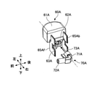
- the pressing heads 60A and 60B and the nozzle portions 70A and 70B in this embodiment will also be described.
- the push heads 60A and 60B and the nozzle portions 70A and 70B are separate members, but fluid communication can be performed by connecting them.
- FIG. 8 shows an enlarged perspective view of the pressing head 60A and the nozzle portion 70A in a separated state.
- FIG. 9 shows a side view of the pressing head 60A and the nozzle portion 70A in a connected state.
- the orientations (front-back direction, left-right direction, vertical direction) of the push head 60A and the nozzle portion 70A in FIGS. 8 and 9 are the orientations when these members are incorporated in the discharge device 100. And.
- the push head 60A has a downstream opening 63A of the flow path 69A (FIG. 3 and the like) on the right side (the side facing the inside of the discharge device 100).
- the nozzle portion 70A has an upstream opening 73A of the flow path 79A (FIG. 3 and the like) on the left side of the nozzle portion base 71A (the side facing the outside of the discharge device 100).
- the push head 60A and the nozzle portion 70A can be fitted to each other, and by this fitting, the center of the push head 60A with the downstream opening 63A and the center of the upstream opening 73A of the nozzle portion 70A are aligned. Then, the flow path 69A of the push head 60A and the flow path 79A of the nozzle portion 70A communicate with each other.
- the pressing head 60A and the nozzle portion 70A are fitted to each other so as to be relatively rotatable. Therefore, the cylindrical discharge portion 72A extending in a direction substantially orthogonal to the extending direction of the nozzle portion base 71A can also rotate around the nozzle portion base 71A or around the center of the upstream opening 73A. ing. That is, the direction of the discharge portion 72A can be arbitrarily determined.
- the push head 60A is provided with a front plate 65Af extending forward along a surface including the vertical direction and the horizontal direction, and extends rearward along the surface including the vertical direction and the horizontal direction.
- a rear plate 65Ab is provided.
- the front plate 65Af has a notch 66Af formed on the center side of the front plate 65Af in the left-right direction
- the rear plate 65Ab also has a notch 66Ab formed on the center side of the rear plate 65Ab in the left-right direction. There is. Since the front plate 65Af and the rear plate 65Ab are formed, it is possible to prevent the structure inside the discharge device 100 from being seen through the front opening 38A when the discharge device 100 is viewed from the front, and the aesthetics of the discharge device 100 are enhanced.
- the tubular discharge portion 72A of the nozzle portion 70A can be passed through the notch 66Af formed in the front plate 65Af. That is, the size and shape of the notch 66Af are set so that the discharge portion 72A can penetrate and extend.
- the discharge portion 72A of the nozzle portion 70A extends through the notch 66Af formed in the front plate 65Af, so that the discharge portion 72A can be supported in the vertical direction. Even if a force is unintentionally applied to the discharge portion 72A in the vertical direction, it is possible to prevent the discharge portion 72A from being damaged.
- the discharge portion 72A does not extend parallel (horizontally) with respect to the front-rear direction, but extends at an angle with respect to the front-rear direction. This is due to the relative positional relationship between the downstream opening 63A to which the nozzle portion 70A is connected and the notch 66Af formed in the front plate 65Af in the pressing head 60A.
- the line Y that passes through the center of the notch 66Af of the front plate 65Af in the vertical direction and along the front-rear direction does not pass through the center O of the downstream opening 63A of the push head 60A. That is, in the pressing head 60A, the notch 66Af is formed so as to be displaced in the vertical direction from the downstream opening 63A.
- the angle of the discharge portion 72A of the nozzle portion 70A with respect to the front-rear direction can be appropriately set depending on the configuration of the push head 60A.
- the discharge portion 72A is configured so that the tip of the discharge portion 72A faces slightly upward.
- the fluid left in the discharge unit 72A after the discharge operation is completed is discharged to the outside of the discharge unit 72A (liquid dripping after the discharge operation). Also called) can be prevented.
- the degree to which the discharge portion 72A faces upward is to prevent liquid dripping. From the viewpoint of improving the effect, it is preferably 9 ° or more. Further, by setting the angle ⁇ to 15 ° or less, it is easy to pick up the discharged fluid, and it is possible to avoid spoiling the aesthetic appearance due to the tip rising extremely.
- the configuration of the push head 60A and the nozzle portion 70A has been described above with reference to FIGS. 8 and 9, but the above description also applies to the push head 60B and the nozzle portion 70B if left-right inverted.
- the combination of the push head 60A and the nozzle portion 70A and the combination of the push head 60B and the nozzle portion 70B are arranged side by side in the discharge device 100.
- FIG. 10 shows a perspective view of the pressing heads 60A and 60B and the nozzle portions 70A and 70B arranged in the discharging device 100 in the non-operating state of the discharging device 100.
- FIG. 11 shows a view of the combination of the push head 60A and the nozzle portion 70A from the right side (FIG. 11A) and a view of the combination of the push head 60B and the nozzle portion 70B from the left side (FIG. 11). (B)) and are shown side by side.
- the combination of the push head 60A and the nozzle portion 70A and the combination of the push head 60B and the nozzle portion 70B are symmetrical.
- the front plate 65Af and the rear plate 65Ab of the pressing head 60A are similarly configured. More specifically, the front plate 65Af and the rear plate 65Ab of the pressing head 60A are configured to be symmetrical with respect to the line X along the left-right direction. That is, the front plate 65Af and the rear plate 65Ab have the same shape, and are arranged at the same positions in the vertical direction and the horizontal direction. The notch 66Af and the notch 66Ab are formed in the same shape and size, and at the same position in the vertical direction and the horizontal direction.
- the front plate 65Af and the rear plate 65Bb of the pressing head 60B are configured symmetrically with respect to the line X along the left-right direction. That is, the front plate 65Af and the rear plate 65Bb have the same shape, and are arranged at the same positions in the vertical direction and the horizontal direction.
- the notch 66Bf and the notch 66Bb are formed in the same shape and size, and at the same position in the vertical direction and the horizontal direction.
- the pressing head 60A and the pressing head 60B which are symmetrical in the front-rear direction, can exhibit the same function even if they are exchanged. Therefore, if the pressing head is formed from one mold, the pressing head can be used as both the pressing head 60A and the pressing head 60B.
- the nozzle portion 70A is also configured to perform the same function regardless of whether the nozzle portion 72A is attached so as to protrude forward or backward. That is, the nozzle portion 70A is formed symmetrically in the front-rear direction when viewed in the attached state shown in FIG. 11A. Similarly, the nozzle portion 70B is also formed symmetrically in the front-rear direction when viewed in the attached state shown in FIG. 11B.
- the nozzle portion 70A can be replaced so that the discharge portion 72A is arranged so as to project rearward through the notch 66Ab of the rear plate 65Ab. Then, the combination of the pressing head 60B and the nozzle portion 70B shown in FIG. 11B is in the same state. Further, in FIG. 11B, the nozzle portion 70B can be replaced so that the discharge portion 72B can be arranged so as to project rearward through the notch 66Bb of the rear plate 65Bb. Then, the combination of the pressing head 60A and the nozzle portion 70A shown in FIG. 11A is in the same state.
- the push head 60A and the push head 60B may have the same shape, and the nozzle portion 70A and the nozzle portion 70B may have the same shape. Therefore, for example, when the member is molded by a molding method using a mold, only one type of mold may be used for manufacturing the pressing heads 60A and 60B, and for manufacturing the nozzle portions 70A and 70B. The type used for is also limited to one type. Therefore, according to this embodiment, the pressing heads 60A and 60B and the nozzle portions 70A and 70B can be manufactured more easily, and the manufacturing cost can be suppressed.
Landscapes
- Engineering & Computer Science (AREA)
- Mechanical Engineering (AREA)
- Chemical & Material Sciences (AREA)
- Dispersion Chemistry (AREA)
- Containers And Packaging Bodies Having A Special Means To Remove Contents (AREA)
- Closures For Containers (AREA)
Abstract
ステムを押し下げることによって収容体内の流動物を吐出可能なポンプユニットをそれぞれ有する2つの吐出器を備えた吐出装置において、前記2つの吐出器の上に、前記ステムを押し下げ可能な押下ヘッドがそれぞれ設けられており、前記押下ヘッドの両方に同時に荷重をかけて当該押下ヘッドを押し下げ可能な操作ボタンが設けられ、非作動状態で前記操作ボタンを下方向に付勢する中央弾性手段が設けられている。
Description
本発明は、吐出装置に関する。
従来、別々の容器(収容体)に収容された2種の流動物を同時に吐出可能な吐出装置若しくは噴出装置が知られている。
例えば、特許文献1に、2液を同時に噴出させ且つ混合させる操作と、所要の1液を選別して噴出させる操作とを容易に選択できる噴出容器が開示されている。特許文献1に開示の噴出容器は、上方付勢させて起立する液体噴出用ステム2の上部に、噴出ノズル11付き押下げヘッド3を付設した、異種液体入りの単体容器1、1を並設する、左右一対をなす二連の容器体を具備する。そして、両押下げヘッド3、3の左右方向内側部部分上面に載置させた押下げ板42上面を押下げすることで両押下げヘッド3、3の同時押下げが可能であると共に、押下げ板42外方へ露出する各押下げヘッド上面部分を押下げすることで押下げヘッドの単独押下げが可能になっている。
特許文献1に開示された構成において2液を同時に噴出させる場合、使用者は、押下げ板42を押し下げる。これにより、押下げ板42が両押下げヘッド3、3を同時に押し下げ、さらに押下げヘッド3、3が液体噴出用ステム2、2をそれぞれ押し下げる。このように、2液を同時に噴出させる動作においては、2つの液体噴出用ステム2、2を押し下げる必要があり、その押し下げのための力(荷重)は、片方の液体噴出用ステム2を押し下げるために要する力の倍以上となり得る。よって、使用者は、押下げ板42の押下げを負担に感じることも多い。
上記の点に鑑みて、本発明の一態様は、別々の容器に収容された流動物を同時に吐出可能な吐出装置において、同時吐出のために要する荷重を軽減することを課題とする。
上記課題を解決するために、ステムを押し下げることによって収容体内の流動物を吐出可能なポンプユニットをそれぞれ有する2つの吐出器を備えた吐出装置であって、前記2つの吐出器の上に、前記ステムを押し下げ可能な押下ヘッドがそれぞれ設けられており、前記押下ヘッドの両方に同時に荷重をかけて当該押下ヘッドを押し下げ可能な操作ボタンが設けられ、非作動状態で前記操作ボタンを下方向に付勢する中央弾性手段が設けられている。
本発明の一態様によれば、別々の容器に収容された流動物を同時に吐出可能な吐出装置において、同時吐出のために要する荷重を軽減できる。
以下、本発明を実施するための形態について図面を参照しながら説明するが、本発明は、明細書及び図面に示された形態に限定されることはない。
図1に、本実施形態の斜視図を示す。図1には、例として、2つの吐出器1A及び1Bを備えた吐出装置100を示す。また、図2に、図1の吐出装置100の分解図を示す。さらに、図3に、図1のI-I線断面図を示す。
図1~図3に示すように、吐出装置100に含まれる吐出器1A、1Bは、流動物がそれぞれ収容された収容体10A、10Bと、流動物を収容体10A、10Bからそれぞれ吐出できるポンプユニット20A、20Bとを備えている。また、流動物は、吐出装置100の側面(収容体10A、10B又は吐出器1A、1Bの側面)からそれぞれ吐出されるように構成されている。すなわち、吐出装置100の吐出部72A、72Bは、側面に配置されている。
本明細書及び図面においては、吐出器1A、1Bが並ぶ方向を左右方向とし、左右方向に直交する方向であって吐出器1A、1Bの軸方向(ポンプユニット20A、20Bの軸方向)を上下方向とし、左右方向及び上下方向に直交する方向を前後方向とする。より具体的には、吐出装置100内部から吐出部72A、72Bが配置されている側に向かう方向を前方向、その反対に向かう方向を後方向と呼び、吐出装置100を前面視で左に向かう方向を左方向、その反対に向かう方向を右方向と呼び、吐出装置100を通常の使用方法で使用する場合に上となる側に向かう方向を上方向、その反対に向かう方向を下方向と呼ぶ。
本形態による吐出装置によって吐出される流動物は、少なくとも吐出時に流動性を示し、吐出装置100の吐出部72A、72Bの吐出口から吐出装置100の外部へと押し出すことができれば限定されない。流動物は、液状物、例えば純物質の液体又は液体混合物であってもよい。さらに、流動物は、例えば、溶液、及びエマルジョン、サスペンション等の分散液等であってもよく、ゲル、スラリー、ペースト、クリーム等と呼ばれる状態のものであってよい。流動物は、粉体を含んでいてよいし、粉体を主として含む、又は粉体から実質的になる若しくは粉体からなっていてもよい。流動物は、上記流動物と、窒素、希ガス、空気等の気体とが混合されて泡状(フォーム状)で収容体に収容されているものであってもよいし、吐出器1A、1Bを作動させることによって、上記気体と混合されて泡状に吐出されるものであってもよい。また、流動物は、水と同様の粘度又は水より小さい粘度を有する状態のものであってもよいし、水より高い粘度を有するペースト状又はクリーム状のものであってよい。本形態による吐出装置100によって吐出される流動物の粘度は、30℃で3000~150000mPa・sであると好ましく、5000~30000mPa・sであるとより好ましい。
流動物は、化粧水、乳液、フェイスクリーム、美容液、洗顔料、クレンジング剤等のスキンケア製品若しくは基礎化粧品、ファンデーション、化粧下地、コンシーラー、リキッドアイシャドー、リキッドチーク、液状リップ製品等のメーキャップ化粧品、日焼け止め剤、ハンドソープ、ボディソープ、ヘアシャンプー、染毛剤、スタイリング剤、ハンドクリーム、ボディクリーム、ボディローション等のパーソナルケア製品(衛生日用品)、フレグランス製品等であってよい。また、流動物は流動性のあるものであれば特に限定されず、上記化粧品等の他、食品(例えば調味料)、塗料等でもあってよい。
本形態の吐出装置100では、吐出器1A又は1Bから流動物を単独で吐出させることができ、又は吐出器1A、1Bから流動物を同時に吐出させることができる。そのため、使用者は、吐出装置100の使用の都度、希望又は状況に応じて、収容体10Aに収容されている第1流動物のみを使用することができるし、収容体10Bに収容されている第2流動物のみを使用することができるし、或いは第1流動物及び第2流動物を同時に吐出させ、自らで混合して得られた混合物を使用することができる。例えば、収容体10Aに収容させる第1流動物を、しっとりタイプの(保湿効果の高い)乳液とし、収容体10Bに収容させる第2流動物を、さっぱりタイプの(爽快感を与える効果の高い)の乳液としておいた場合、使用者は、しっとりタイプの乳液、及びさっぱりタイプの乳液のどちらかを吐出装置100から吐出させて使用することができるし、しっとりタイプの乳液とさっぱりタイプの乳液との両方を吐出させて、両乳液の中間の使用感を供する乳液混合物を使用することができる。このように、本形態による吐出装置100は、化粧品又はパーソナルケア製品のため、特に乳液等のスキンケア製品、ファンデーション等のベースメーク化粧品、アイシャドウなどのポイントメーク製品のための吐出装置として好適に用いることができる。
吐出器1A、1Bはそれぞれ、収容体10A、10Bと、収容体10A、10Bの上に配置されたポンプユニット20A、20Bと備えたポンプ式吐出器とすることができる。ポンプユニット20A、20Bにおけるポンプの形式は特に限定されず、流動物を吐出させる吐出器又はディスペンサで使用される公知の形式であってよい。ポンプユニット20A、20Bは、例えば、ステム若しくはピストンを摺動させることによってポンプユニットにおける室内の圧力を変更可能であり、室内の圧力が高められた時に流動物を吐出可能なものであってよい。
図2及び図3に示すように、ポンプユニット20A、20Bは、上下方向に摺動可能なステム22A、22Bをそれぞれ備えている。ステム22A、22Bは、収容体10A、10Bに対して相対的に、上下方向に摺動可能である。吐出器1A、1Bを操作する際には、ステム22A、22Bは、収容体10A、10Bに向かって、すなわち下方向に押し下げられる。図3に示すように、ポンプユニット20A、20Bは、流動物が中空のステム22A、22B内を通って移送されるのものであってよい。また、ポンプユニット20A、20Bは、その他の公知の方式でステム22A、22Bが摺動して吐出器1A、1Bを作動させるものであってもよい。また、ステム22A、22Bは、圧縮ばね等のポンプユニット弾性手段25A、25Bにそれぞれ接続されている。このポンプユニット弾性手段25A、25Bによって、一旦押し下げられたステム22A、22Bが容易に元の位置に戻るようになっている(後に詳述)。
ポンプユニット20A、20Bによって収容体10A、10Bから送り出された流動物はそれぞれ、吐出器1A、1B内の所定の流路を通って、所定の吐出口からそれぞれ吐出装置100の外部へと吐出させることができる。本形態では、ポンプユニット20A、20Bによって押し出された流動物は、最終的には、ノズル部70A、70B内の流路79A、79Bを通って、それぞれ吐出部72A、72Bから吐出装置100の外部へ吐出するよう構成されている。図示の形態では、吐出部72A、72Bは、吐出装置100の前面から前方へと突出する筒状ノズル、好ましくは円筒状ノズルの形態となっている。
吐出器1A、1Bからの流動物の吐出についてより具体的に説明すると、図2及び図3に示すように、吐出器1A、1Bの上方には、押下ヘッド60A、60Bがそれぞれ配置されている。押下ヘッド60A、60Bは、下側に、下方突出部64A、64Bを備えている。そして、下方突出部64A、64Bは、ポンプユニット20A、20Bのステム22A、22Bの上部に形成された受容部に嵌め合わされ、これにより、押下ヘッド60A、60Bとステム22A、22Bとが結合されている。また、押下ヘッド60A、60Bの頂面61A、61Bは上方に露出しており、使用者はこの頂面61A、61Bに指を置き、押下ヘッド60A、60Bを下方向に押すことができる。押下ヘッド60A、60Bを押し下げることによって、ステム22A、22Bを押し下げることができる。なお、押下ヘッド60A、60Bの頂面61A、61Bは、押し易さ及び審美性の観点から、平坦になっていることが好ましい。一方、押下ヘッド60A、60Bは、左右方向で見て中心側で、ノズル部70A、70Bとそれぞれ嵌合によって結合されている。
ステム22A、22B、押下ヘッド60A、60B、及びノズル部70A、70Bはそれぞれ流体連通している。よって、収容体10A、10Bに収容されている流動物は、ステム22A、22B、押下ヘッド60A、60B、及びノズル部70A、70B内を、この順に通って吐出され得る。例えば、収容体10Aに収容されている第1流動物は、中空のステム22A内の流路29Aを通って上方向に移動し、さらに、押下ヘッド60A内の流路69A及びノズル部70A内の流路79Aを順に通って左右方向の中央に向かってに導かれ、さらに、前面に配置された吐出部72A(図1及び図2)から吐出され得る。収容体10Bに収容されている第2流動物も同様に吐出され得る。
本形態では、ノズル部70Aとノズル部70Bとは別個になっており、連通していない。別言すると、2種の流動物を別々に、吐出部72A、72Bそれぞれから外部へと吐出できる。すなわち、本吐出装置100では、2種の流動物が外部へ吐出される前に混合されることがないので、混合によって粘度、又はその他の流動に関連する特性が変化し得る2種の流動物を収容体10A、10Bにそれぞれ収容していたとしても、2種の流動物が吐出装置100内で詰まる可能性を低減できる。
本形態では、吐出器1A、1Bは同じ構成を有する。すなわち、ポンプユニット20A、20Bは同じ構成を有する。しかし、吐出器1A、1Bは、ステム(若しくはピストン)を摺動させることによって流動物を吐出可能なものであれば、異なる構成を有していてもよい。なお、ポンプユニット20A、20Bは、流動物をそのまま吐出させるものであってもよいし、流動物を気体と混合して泡状に吐出させるものであってもよい。
吐出器1A、1Bは、それぞれ胴部30に固定されており、これによって互いの位置も固定されている。より具体的には、胴部30に形成された開口32A、32Bのそれぞれに、吐出器1A、1Bが、嵌合又は螺合により固定されていてよい。その場合、収容体10A、10Bに固定されたポンプユニット20A、20Bが開口32A、32Bに固定されていてもよいし、収容体10A、10B自体が開口32A、32Bに固定されていてもよい。
また、胴部30の前面には、前開口38A、38Bが形成されている。上述のノズル部70A、70Bの吐出部72A、72Bは、胴部30の前開口38A、38Bを通って前方に突出している(図1)。
次に、本形態による吐出装置100の作動方式について、図3~図6を参照しながら説明する。上述したように、本形態による吐出装置100においては、吐出器1Aから収容体10Aに収容された第1流動物のみを吐出させる第1操作、吐出器1Bから収容体10Bに収容された第2流動物のみを吐出させる第2操作、及び吐出器1A、1Bから第1流動物及び第2流動物を同時に吐出させる第3操作の3種の操作を行うことができる。
図3(a)は、図1のI-I線断面図である。また、図3(b)には、図3(a)の状態にある吐出装置100の部分斜視図を示す。図3(a)及び(b)に示す状態は、使用者が吐出装置100に力を加えておらず、吐出装置100が作動していない状態、すなわち非作動状態である。この状態では、押下ヘッド60A及び押下ヘッド60Bはいずれも最高位置にあり、押下ヘッド60Aの頂面61A及び押下ヘッド60Bの頂面61Bは、操作ボタン80(後述)の頂面81と面一になっている。
図4(a)は、図3(a)に対応する断面図であり、上記の第1操作(吐出器1Aから第1流動物のみを吐出させる操作)のために、押下ヘッド60Aのみが押し下げられた状態を示す。また、図4(b)には、図4(a)の状態にある吐出装置100の部分斜視図を示す。図4(a)及び(b)に示すように、当該第1操作においては、押下ヘッド60A、ノズル部70A、及びステム22Aが下方向に動かされている。第1操作により、ポンプユニット20Aが作動し、収容体10A内の第1流動物を吐出させることができる。図4(a)及び(b)より明らかであるように、第1操作においては、押下ヘッド60B、ノズル部70B、及びステム22Bは動かされていない。すなわち、第1操作によって吐出器1Bには何の影響もなく、吐出器1Bからは第2流動物は吐出されない。
上述のように、ポンプユニット20A、20Bはそれぞれ、ステム22A、22Bが押し下げられた後にステム22A、22Bが元の位置に戻るようにするため、ポンプユニット弾性手段25A、25Bをそれぞれ備えている。ポンプユニット弾性手段25A、25Bは、例えば圧縮ばね、好ましくは圧縮コイルばねであってよい。図4の例では、ステム22Aの下方向の移動に伴って、ポンプユニット弾性手段25Aが圧縮される。この圧縮によって、ポンプユニット弾性手段25Aには、弾性手段が圧縮前の状態に戻ろうとする応力(復元応力)が発生するので、使用者が押下ヘッド60Aに掛けていた力を解除すると、ポンプユニット弾性手段25Aは自然に伸びて元の長さに戻る。これにより、ポンプユニット弾性手段25Aの上に配置されているステム22A、並びにステム22Aに接続されている押下ヘッド60A及びノズル部70Aは自動的に押し上げられて、元の位置(図3に示す状態)に戻ることができる。
図5(a)は、図3(a)に対応する断面図であり、第2操作(吐出器1Bから第2流動物のみを吐出させる操作)のために、押下ヘッド60Bのみが押し下げられた状態を示す。また、図5(b)には、図5(a)の状態にある吐出装置100の部分斜視図を示す。図5(a)及び(b)に示すように、当該第2操作においては、押下ヘッド60B、ノズル部70B、及びステム22Bが下方向に動かされている。この第2操作により、ポンプユニット20Bが作動し、収容体10B内の第2流動物を吐出させることができる。図5(a)及び(b)より明らかであるように、第2操作においては、第1操作とは反対に、押下ヘッド60A、ノズル部70A、及びステム22Aは動かされていない。すなわち、第2操作によって吐出器1Aには何の影響もなく、吐出器1Aからは第1流動物は吐出されない。
第2操作における、ポンプユニット弾性手段25Bの動作及び機能は、第1操作におけるポンプユニット弾性手段25Aと同様である。使用者が図5に示すように押下ヘッド60Bを下方に押すことによって、その下に配置されているステム22Bが押し下げられ、ポンプユニット弾性手段25Bが圧縮される。そして、ポンプユニット弾性手段25Bに掛けられていた押圧が解除されると、ポンプユニット弾性手段25Bは伸びて元の状態に戻るので、ポンプユニット弾性手段25Bの上に配置されているステム22B、並びにステム22Bに接続されている押下ヘッド60B及びノズル部70Bは自動的に押し上げられて、元の状態(図3に示す状態)に戻ることができる。
続いて、図6を参照して、第3操作(吐出器1A、1Bから流動物を同時に吐出させるための操作)について説明する。図6(a)は、図3(a)に対応する断面図であり、図6(b)は、図6(a)の状態にある吐出装置100の部分斜視図である。図6(a)及び(b)に示すように、第3操作の際には、使用者は、左右方向の中央に配置されている操作ボタン80を下方向に押す。
操作ボタン80は、押下ヘッド60Aの一部及び押下ヘッド60Bの一部とそれぞれ上下方向に重なるように配置されている。より具体的には、操作ボタン80は、下方に向かって延びる押圧部82A、82Bを有しており、この押圧部82A、82Bが、押下ヘッド60A、60Bの受圧面62A、62B(図2も参照)と上下方向で重なっている。本形態では、押圧部82A、82Bは、図2に示すように前後方向に沿って延在する壁状になっており、前後方向にわたって受圧面62A、62Bと接触して受圧面62A、62Bを下方向に押すことができる。第3操作において、操作ボタン80は、傾くことなく、上下方向に沿って下方向に移動する。すなわち、非作動状態で水平方向に沿って延在していた操作ボタン80の頂面81は、第3操作後も水平方向に沿って延在している。
本形態では、図3に示すように、操作ボタン80の押圧部82Aの下端が押下ヘッド60Aの受圧面62Aと接触する位置と、操作ボタン80の押圧部82Bが押下ヘッド60Bの受圧面62Bと接触する位置とは、上下方向で見てほぼ同じである。そのため、操作ボタン80を下方向に押すと、押下ヘッド60A、60Bは、受圧面62A、62Bで操作ボタン80からの力を受けて、同時に、同行程で押し下げられる。そして、押下ヘッド60Aが押し下げられることによってステム22Aが、また押下ヘッド60Bが押し下げられることによってステム22Bが押し下げられる。よって、ポンプユニット20A、20Bが同時に作動し、収容体10A、10Bからそれぞれ流動物を吐出させることができる。
なお、図示の形態では、操作ボタン80の頂面81から押圧部82Aの下端までの長さと、操作ボタン80の頂面81から押圧部82Bの下端までの長さは同じであるので、操作ボタン80の押圧によって押し下げられる押下ヘッド60A、60Bの行程は、同じである。しかし、操作ボタン80の頂面81から押圧部82Aの下端までの長さと、操作ボタン80の頂面81から押圧部82Bの下端までの長さを異ならせて構成してもよい。
第3操作において、使用者が操作ボタン80を押し下げることによって両方の押下ヘッド60A、60Bを押し下げた時には、押下ヘッド60A、60Bの下に配置されているステム22A、22Bの下に配置されているポンプユニット弾性手段25A、25Bが同時に圧縮される。そして、使用者が押下ヘッド60A、60Bに掛けていた力を解除すると、ポンプユニット弾性手段25A、25Bが伸びて元の長さに戻るので、ステム22A、22B、及び押下ヘッド60A、60Bが押し上げられ、さらには操作ボタン80も押し上げられて元の状態(非作動状態、図3)に戻る。
しかしながら、第1操作及び第2操作とは異なり、第3操作においては、押下ヘッド60A、60Bの両方を押し下げる必要があるので、従来の構成では、第3操作においては、第1操作又は第2操作で要する力よりも大きな力を要する。例えば、吐出器1A及び押下ヘッド60Aからなるユニットの構成と、吐出器1B及び押下ヘッド60Bからなるユニットの構成とが同じである場合には、第1操作又は第2操作に要する力の少なくとも2倍の力を要する。さらに、操作ボタン80の構成、操作ボタン80の押圧部82Aの位置とステム22Aの位置との関係(左右方向の距離)及び操作ボタン80の押圧部82Bの位置とステム22Bの位置との関係(左右方向の距離)によっては、第1操作又は第2操作に要する力の2倍を超える力を要する場合がある。よって、第3操作は、特に押下ヘッド60A、60Bの押し下げによってポンプユニット弾性手段25A、25Bに発生する応力が大きい場合には、第1操作及び第2操作に比べて行い難い傾向がある。
これに対し、本形態では、第3操作で操作ボタン80を押し下げる動作をより容易にできるようになっている。すなわち、図2~図6に示すように、操作ボタン80の下に、荷重軽減部40が設けられている。荷重軽減部40の構成及び機能についての理解を深めるため、図7に、図1のII-II線断面図を示す。
図3及び図7に示すように、荷重軽減部40は、中央弾性手段45を備えている。中央弾性手段45は、好ましくは圧縮ばねであり、より好ましくは圧縮コイルばねである。例えば図3に示す非作動状態で、圧縮ばね(中央弾性手段)45は、圧縮された状態になっていて、第3操作において操作ボタン80を下方向に押し下げる動作に要する力(荷重)を軽減することができる。
本形態では、荷重軽減部40は、圧縮コイルばねである中央弾性手段45に加え、中央弾性手段45の中央に配置された芯棒41をさらに備えている。この荷重軽減部40は、胴部30の中央孔35内において摺動可能に配置されている。芯棒41は、操作ボタン80の前後方向及び左右方向の中央に下方に突出している下方突出部85(図7も参照)に結合している。下方突出部85の下面には凹部85dが形成されており、この凹部85dに芯棒41の上端部41tが嵌め込まれ、固く結合されている。よって、操作ボタン80の動きに伴って、芯棒41も動く。すなわち、操作ボタン80が押し下げられると、芯棒41も、胴部30の中央孔35内を下方向に移動する。
芯棒41は下方に、より大きな径を有する拡径部41bを有しており、その径は、中央弾性手段45が下方に抜け落ちないような大きさとなっている。これにより、拡径部41bは、中央弾性手段45の下方向への動きを止める機能を有する。なお、拡径部41bの径は、拡径部41bが、胴部30の中央孔35の内壁に接触して摺動可能な大きさであると、芯棒41が左右方向及び前後方向にブレずに上下方向に沿って安定して摺動できるので好ましい。
また、中央孔35の上部の径は小さくなっており、段部35sが形成されている。これにより、芯棒41は中央孔35内を摺動できるが、中央弾性手段45は、段部35sより上方へ移動できないようになっている。別言すると、段部35sは、中央弾性手段45の上方向への動きを止める機能を有する。
このように、中央弾性手段45は、胴部30の中央孔35の段部35sの下面と、芯棒41の拡径部41bの上面との間に収容されている。そして、本形態では、非作動状態で、胴部30の中央孔35の段部35sの下面と芯棒41の拡径部41bの上面との距離は、中央弾性手段(圧縮コイルばね)45の長さより短くなるよう構成されている。そのため、少なくとも非作動状態(吐出装置100の非作動状態若しくは操作ボタン80の非作動状態)では、中央弾性手段45は圧縮状態となっている。中央弾性手段45が圧縮状態にあることで、中央弾性手段45には、元の状態に戻ろうとする若しくはばねが伸びようとする応力(復元応力)が発生している。よって、中央弾性手段45によって、胴部30の中央孔35の段部35sの下面に上方向の力が掛かり、一方で、芯棒41の拡径部41bの上面に下方向の力が掛かる。ここで、上述のように芯棒41は操作ボタン80に固定され、芯棒41と操作ボタン80とは一体化されているので、芯棒41の拡径部41bに掛かる力は、操作ボタン80にも伝わる。よって、図3に示す非作動状態では、中央弾性手段45によって、操作ボタン80は下方向に付勢されている。
上述のように、第3操作においては、使用者は操作ボタン80を下方向に押し下げるが(図6)、本形態では、中央弾性手段45によって操作ボタン80が下方向に付勢されているために、使用者が操作ボタン80を押し下げるために要する力(荷重)を軽減することができる。これにより、第3操作に要する力と、第1操作及び第2操作に要する力との差を小さくでき、使用者は、いずれの操作も違和感なく行うことができる。
第3操作においては、通常使用者は、操作ボタン80を押し始める時に負担(荷重)を感じやすい。本形態では、中央弾性手段45には、吐出装置100の非作動状態(図3)で最大応力を発生するので、操作ボタン80の押し始めに要する力を効果的に軽減できる。
第3操作において、使用者が操作ボタン80を下方向に最大限押し下げた際、中央弾性手段45は、元の長さを有していて復元応力が発生していない状態になっていても、復元応力が発生している圧縮状態になっていてもよい。しかし、最大限押し下げ時に中央弾性手段45に復元応力が発生する構成では、使用者が操作ボタン80の押し下げに要する荷重を軽減する作用を、押下げの操作を通して持続させることができるので、好ましい。
本形態では、吐出器1A、1Bのポンプユニット20A、20Bに設けられているポンプユニット弾性手段25A、25Bによって操作ボタン80に上方向に掛かる力(ポンプユニット弾性手段25Aによって掛かる力及びポンプユニット弾性手段25Bによって掛かる力の合計)は、中央弾性手段45によって操作ボタン80に下方向に掛かる力より大きいと好ましい。そのためには、例えば、ポンプユニット弾性手段25Aのばね定数及びポンプユニット弾性手段25Bのばね定数の合計を、中央弾性手段45のばね定数より大きくすることができる。これにより、使用者が操作を行っていない非作動状態若しくは静止状態で、操作ボタン80の頂面81を最高位置に維持することができる。さらに、例えば一方の押下ヘッド60Aを押し下げた状態でも、操作ボタン80が非作動位置に戻ることができるように、ポンプユニット弾性手段25Bの復元力が調節されていることが好ましい。同様に、押下ヘッド60Bを押し下げた状態でも、操作ボタン80が非作動位置に戻ることができるように、ポンプユニット弾性手段25Aの復元力が調節されていることが好ましい。
また、ポンプユニット弾性手段25A、25Bのいずれか一方によって操作ボタン80に上方向に掛かる力を、中央弾性手段45によって操作ボタン80に下方向に掛かる力より大きくすることができる。そのために、例えば、ポンプユニット弾性手段25Aのばね定数及びポンプユニット弾性手段25Bのばね定数をそれぞれ、中央弾性手段45のばね定数より大きくすることができる。これにより、押下ヘッド60A、60Bのいずれかを押し下げた状態で操作ボタン80を押し下げた場合でも、押圧を解除した際に操作ボタン80が元の位置に戻り得る。
さらに、中央弾性手段45、ポンプユニット弾性手段25A、及びポンプユニット弾性手段25Bがいずれも圧縮ばねである場合、中央弾性手段45、ポンプユニット弾性手段25A、及びポンプユニット弾性手段25Bとして、ほぼ同じばね定数のばねを使用してもよい。これにより、ポンプユニット弾性手段25Aのみを圧縮するために必要な力、及びポンプユニット弾性手段25Aのみを圧縮するために必要な力、並びにポンプユニット弾性手段25A及びポンプユニット弾性手段25Bを同時に圧縮するために必要な力から中央弾性手段45によって軽減される力を引いた所要力をほぼ等しくすることができる。
本形態による吐出装置100は、上述の第1操作、第2操作、及び第3操作以外の操作方法で、操作することもできる。例えば、操作ボタン80を押さずに、押下ヘッド60A、60Bを同時に押すことができる。その場合、使用者は、押下ヘッド60A、60Bの押し下げ行程を異ならせて、吐出器1A、1Bからの流動物の吐出量を調整することもできる。
以下、本形態における押下ヘッド60A、60B及びノズル部70A、70Bについても説明する。上述のように、押下ヘッド60A、60Bとノズル部70A、70Bとは別個の部材であるが、接続することによって流体連通させることができる。
図8に、押下ヘッド60A及びノズル部70Aの、分離された状態での拡大斜視図を示す。図9に、押下ヘッド60A及びノズル部70Aの、接続された状態での側面図を示す。説明を簡単にするために、図8及び図9における押下ヘッド60A及びノズル部70Aの向き(前後方向、左右方向、上下方向)は、これらの部材が吐出装置100に組み込まれた状態での向きとする。
図8に示すように、押下ヘッド60Aは、右側(吐出装置100の内部を向く側)に、流路69A(図3等)の下流開口部63Aを有する。一方、ノズル部70Aは、ノズル部基部71Aの左側(吐出装置100の外部を向く側)に、流路79A(図3等)の上流開口部73Aを有している。そして、押下ヘッド60Aとノズル部70Aとは嵌合可能になっており、この嵌合により、押下ヘッド60Aの下流開口部63Aとの中央とノズル部70Aの上流開口部73Aの中央とが位置合わせされ、押下ヘッド60Aの流路69Aとノズル部70Aの流路79Aとが連通する。
押下ヘッド60Aとノズル部70A(ノズル部基部71A)とは、互いに相対回転可能に嵌合される。よって、ノズル部基部71Aの延在方向に対して略直交する方向に延在する筒状の吐出部72Aも、ノズル部基部71Aの周りを又は上流開口部73Aの中心の周りを回転可能となっている。すなわち、吐出部72Aの向きを任意に決定することができる。
一方、押下ヘッド60Aには、前方に、上下方向及び左右方向を含む面に沿って延在する前板65Afが設けられており、後方に、上下方向及び左右方向を含む面に沿って延在する後板65Abが設けられている。そして、前板65Afには、当該前板65Afの左右方向の中央側に切欠66Afが形成されており、後板65Abにも、当該後板65Abの左右方向の中央側に切欠66Abが形成されている。前板65Af及び後板65Abが形成されていることで、吐出装置100を正面から見た時に前開口38Aを通して吐出装置100内の構造が見えることを防止でき、吐出装置100の審美性が高まる。
図9に示すように、押下ヘッド60Aとノズル部70Aとを接続する際には、ノズル部70Aの筒状の吐出部72Aを、前板65Afに形成された切欠66Afに通すことができる。すなわち、切欠66Afの大きさ及び形状は、吐出部72Aが貫通して延在できるように設定されている。ノズル部70Aの吐出部72Aが、前板65Afに形成された切欠66Afの間を通って延在することで、吐出部72Aが上下方向で支持され得る。吐出部72Aに上下方向に意図せず力が掛かった場合でも、吐出部72Aが損傷することを防止できる。
図9に示す例では、吐出部72Aは、前後方向に対して平行に(水平に)延在しておらず、前後方向に対して角度をなして延在している。これは、押下ヘッド60Aにおける、ノズル部70Aが接続される下流開口部63Aと、前板65Afに形成された切欠66Afとの相対的な位置関係に起因する。図9に示すように、前板65Afの切欠66Afの上下方向の中央を通り且つ前後方向に沿った線Yは、押下ヘッド60Aの下流開口部63Aの中心Oを通らない。すなわち、押下ヘッド60Aにおいては、切欠66Afが、下流開口部63Aから上下方向にずらされて形成されている。
このように、ノズル部70Aの吐出部72Aの、前後方向に対する角度は、押下ヘッド60Aの構成によって適宜設定することができる。図9の例では、吐出部72Aは、当該吐出部72Aの先端がやや上を向くように構成されている。吐出部72Aの先端が上を向くように構成することで、吐出動作を終えた後に吐出部72A内に残された流動物が吐出部72Aの外部に排出されること(吐出動作後の液垂れともいう)を防止できる。なお、吐出部72Aが上を向く程度、すなわち吐出部72Aの中心線CLが、前後方向(或いは切欠66Afの中心Oを通り且つ前後方向に沿った線Y)に対する角度αは、液垂れ防止の効果を向上させるという観点からは、9°以上とすることが好ましい。また、角度αを15°以下とすることで、吐出された流動物を手に取り易く、また先端が極端に起き上がることで見た目の美しさが損なわれることを回避できる。
以上、図8及び図9を参照して押下ヘッド60A及びノズル部70Aの構成について説明したが、上述の説明は、左右反転させれば、押下ヘッド60B及びノズル部70Bにも当てはまる。押下ヘッド60Aとノズル部70Aとの組合せ、及び押下ヘッド60Bとノズル部70Bとの組合せは、吐出装置100においては左右に並べて配置される。
図10に、吐出装置100の非作動状態で、吐出装置100内に配置された押下ヘッド60A、60B及びノズル部70A、70Bの斜視図を示す。さらに、図11に、押下ヘッド60Aとノズル部70Aとの組合せを右側から見た図(図11(a))と、押下ヘッド60Bとノズル部70Bとの組合せを左側から見た図(図11(b))とを並べて示す。図10及び図11に示すように、押下ヘッド60Aとノズル部70Aとの組合せ、及び押下ヘッド60Bとノズル部70Bとの組合せは、左右対称である。
さらに、図10及び図11(a)に示すように、押下ヘッド60Aの前板65Afと後板65Abとは、同様に構成されている。より具体的には、押下ヘッド60Aの前板65Afと後板65Abとは、左右方向に沿った線Xに対して前後対称に構成されている。すなわち、前板65Afと後板65Abとは同じ形状を有しており、上下方向及び左右方向で同じ位置に配置されている。そして、切欠66Afと切欠66Abとは、同じ形状及び大きさ、並びに上下方向及び左右方向で同じ位置に形成されている。
同様のことが、押下ヘッド60Bについてもいえる。図10及び図11(b)に示すように、押下ヘッド60Bの前板65Afと後板65Bbとは、左右方向に沿った線Xに対して前後対称に構成されている。すなわち、前板65Afと後板65Bbとは同じ形状を有しており、上下方向及び左右方向で同じ位置に配置されている。そして、切欠66Bfと切欠66Bbとは、同じ形状及び大きさ、並びに上下方向及び左右方向で同じ位置に形成されている。
このような前後対称である押下ヘッド60Aと押下ヘッド60Bとは、交換しても同じ機能を発揮することができる。よって、1つの型から押下ヘッドを形成すれば、その押下ヘッドは、押下ヘッド60Aとしても押下ヘッド60Bとしても使用できる。
さらに、ノズル部70Aも、吐出部72Aが前方に突出するように取り付けても、後方に突出するように取り付けても、同じ機能を果たすように構成されている。すなわち、図11(a)に示す取り付けられた状態で見て、ノズル部70Aは前後対称に形成されている。同様に、ノズル部70Bも、図11(b)に示す取り付けられた状態で見て、前後対称に形成されている。
よって、図11(a)において、ノズル部70Aを付け替えて、吐出部72Aが、後板65Abの切欠66Abを通って後方に突出するように配置することができる。そうすると、図11(b)に示す押下ヘッド60B及びノズル部70Bの組合せと同じ状態となる。また、図11(b)において、ノズル部70Bを付け替えて、吐出部72Bが、後板65Bbの切欠66Bbを通って後方に突出するように配置することができる。そうすると、図11(a)に示す押下ヘッド60A及びノズル部70Aの組合せと同じ状態となる。
このように、押下ヘッド60Aと押下ヘッド60Bと同じ形状であってよく、ノズル部70Aとノズル部70Bとは同じ形状であってよい。そのため、例えば、部材が型を用いた成形方法によって成形される場合には、押下ヘッド60A、60Bの製造のために用いられる型は1種類であってよく、ノズル部70A、70Bの製造のために用いられる型も1種類であってよい。よって、本形態によれば、押下ヘッド60A、60B及びノズル部70A、70Bの製造がより容易になり、製造コストも抑えることができる。
本出願は、日本特許庁に2020年8月11日に出願された基礎出願2020-135966号の優先権を主張するものであり、その全内容を参照によりここに援用する。
1A、1B 吐出器
10A、10B 収容体
20A、20B ポンプユニット
22A、22B ステム
25A、25B ポンプユニット弾性手段
30 胴部
32A、32B 開口
35 胴部の中央孔
38A、38B 前開口
40 荷重軽減部
41 芯棒
41t 芯棒の上端部
41b 芯棒の拡径部
45 中央弾性手段
60A、60B 押下ヘッド
62A、62B 押下ヘッドの受圧面
63A、63B 下流開口部
64A、64B 押下ヘッドの下方突出部
65Af、65Bf 前板
66Af、66Bf 前板の切欠
65Ab、65Bb 後板
66Ab、66Bb 後板の切欠
69A、69B 流路
70A、70B ノズル部
71A、71B ノズル部基部
72A、72B 吐出部
73A、73B 上流開口部
79A、79B 流路
80 操作ボタン
82A、82B 操作ボタンの押圧部
85 操作ボタンの下方突出部
85d 操作ボタンの凹部
100 吐出装置
Claims (4)
- ステムを押し下げることによって収容体内の流動物を吐出可能なポンプユニットをそれぞれ有する2つの吐出器を備えた吐出装置であって、
前記2つの吐出器の上に、前記ステムを押し下げ可能な押下ヘッドがそれぞれ設けられており、
前記押下ヘッドの両方に同時に荷重をかけて当該押下ヘッドを押し下げ可能な操作ボタンが設けられ、
前記操作ボタンを下方向に付勢する中央弾性手段が設けられている、吐出装置。 - 前記中央弾性手段が圧縮ばねである、請求項1に記載の吐出装置。
- 前記ポンプユニットがそれぞれ、押し下げられた前記ステムを上方向に付勢可能なポンプユニット弾性手段を備え、
両ポンプユニット弾性手段によって前記操作ボタンに上方向に掛かる力が、前記中央弾性手段によって前記操作ボタンに下方向に掛かる力より大きい、請求項1又は2に記載の吐出装置。 - 前記中央弾性手段がコイルばねであり、
前記操作ボタンに接続する芯棒が設けられており、前記芯棒が前記コイルばね内に配置されている、請求項1から3のいずれか一項に記載の吐出装置。
Priority Applications (1)
| Application Number | Priority Date | Filing Date | Title |
|---|---|---|---|
| JP2022542625A JP7757584B2 (ja) | 2020-08-11 | 2021-07-29 | 吐出装置 |
Applications Claiming Priority (2)
| Application Number | Priority Date | Filing Date | Title |
|---|---|---|---|
| JP2020-135966 | 2020-08-11 | ||
| JP2020135966 | 2020-08-11 |
Publications (1)
| Publication Number | Publication Date |
|---|---|
| WO2022034799A1 true WO2022034799A1 (ja) | 2022-02-17 |
Family
ID=80247177
Family Applications (1)
| Application Number | Title | Priority Date | Filing Date |
|---|---|---|---|
| PCT/JP2021/028125 Ceased WO2022034799A1 (ja) | 2020-08-11 | 2021-07-29 | 吐出装置 |
Country Status (2)
| Country | Link |
|---|---|
| JP (1) | JP7757584B2 (ja) |
| WO (1) | WO2022034799A1 (ja) |
Citations (4)
| Publication number | Priority date | Publication date | Assignee | Title |
|---|---|---|---|---|
| JPS6333921U (ja) * | 1986-08-21 | 1988-03-04 | ||
| JP2001158485A (ja) * | 1999-11-30 | 2001-06-12 | Yoshino Kogyosho Co Ltd | エアゾール式噴霧器 |
| JP2002311552A (ja) * | 2001-04-13 | 2002-10-23 | Noritsu Koki Co Ltd | 処理液補充装置 |
| JP2011201592A (ja) * | 2010-03-26 | 2011-10-13 | Yoshino Kogyosho Co Ltd | 多連式吐出容器 |
Family Cites Families (3)
| Publication number | Priority date | Publication date | Assignee | Title |
|---|---|---|---|---|
| JP5409477B2 (ja) | 2010-03-26 | 2014-02-05 | 株式会社吉野工業所 | 多連式吐出容器 |
| JP6416515B2 (ja) | 2014-04-03 | 2018-10-31 | 株式会社ダイゾー | 吐出容器 |
| JP2019189259A (ja) | 2018-04-20 | 2019-10-31 | 株式会社 資生堂 | 吐出器、及び吐出装置 |
-
2021
- 2021-07-29 JP JP2022542625A patent/JP7757584B2/ja active Active
- 2021-07-29 WO PCT/JP2021/028125 patent/WO2022034799A1/ja not_active Ceased
Patent Citations (4)
| Publication number | Priority date | Publication date | Assignee | Title |
|---|---|---|---|---|
| JPS6333921U (ja) * | 1986-08-21 | 1988-03-04 | ||
| JP2001158485A (ja) * | 1999-11-30 | 2001-06-12 | Yoshino Kogyosho Co Ltd | エアゾール式噴霧器 |
| JP2002311552A (ja) * | 2001-04-13 | 2002-10-23 | Noritsu Koki Co Ltd | 処理液補充装置 |
| JP2011201592A (ja) * | 2010-03-26 | 2011-10-13 | Yoshino Kogyosho Co Ltd | 多連式吐出容器 |
Also Published As
| Publication number | Publication date |
|---|---|
| JP7757584B2 (ja) | 2025-10-22 |
| JPWO2022034799A1 (ja) | 2022-02-17 |
Similar Documents
| Publication | Publication Date | Title |
|---|---|---|
| US20070034718A1 (en) | Improvements in or relating to nozzle devices | |
| EP2211659B1 (en) | Rotary actuated lotion pump | |
| US20110139813A1 (en) | Portable dispensing systems | |
| KR200469033Y1 (ko) | 복수의 에어리스 화장품 용기를 갖는 내용물 혼합 배출 용기 | |
| KR102164743B1 (ko) | 복수의 내용물을 동시에 배출할 수 있는 화장품용기 조립체 | |
| US20060198692A1 (en) | Fingertip dispenser, typically for a cosmetic product | |
| KR200482091Y1 (ko) | 파우치 용기를 구비한 수직 가압 콤팩트 용기 | |
| CN111407064B (zh) | 化妆品用三角形容器 | |
| US20090317167A1 (en) | Delivery system | |
| JP7757584B2 (ja) | 吐出装置 | |
| TW201943616A (zh) | 噴出器及噴出裝置 | |
| JP7757585B2 (ja) | 吐出装置 | |
| EP4454764A1 (en) | Liquid contents ejection container having nozzle blocking structure | |
| KR102018557B1 (ko) | 이종 화장료 화장품 용기 | |
| JP7461790B2 (ja) | 吐出装置 | |
| US11957232B2 (en) | Applicator system for applying a cosmetic product | |
| WO2025160926A1 (en) | Pump dispenser | |
| KR102244482B1 (ko) | 복합형 화장품 용기 | |
| CN221749845U (zh) | 一种具有多腔体结构的化妆品容器瓶 | |
| KR102067958B1 (ko) | 이종 화장료 화장품 용기 | |
| KR20190049652A (ko) | 이종 화장료 화장품 용기 | |
| JP2017197209A (ja) | 液剤吐出容器 | |
| KR102636711B1 (ko) | 가압 토출 용기 | |
| CN224206363U (zh) | 一种按压涂抹容器 | |
| JP7442398B2 (ja) | 吐出ポンプ |
Legal Events
| Date | Code | Title | Description |
|---|---|---|---|
| 121 | Ep: the epo has been informed by wipo that ep was designated in this application |
Ref document number: 21855878 Country of ref document: EP Kind code of ref document: A1 |
|
| ENP | Entry into the national phase |
Ref document number: 2022542625 Country of ref document: JP Kind code of ref document: A |
|
| NENP | Non-entry into the national phase |
Ref country code: DE |
|
| 122 | Ep: pct application non-entry in european phase |
Ref document number: 21855878 Country of ref document: EP Kind code of ref document: A1 |