WO2022025075A1 - モータ - Google Patents
モータ Download PDFInfo
- Publication number
- WO2022025075A1 WO2022025075A1 PCT/JP2021/027787 JP2021027787W WO2022025075A1 WO 2022025075 A1 WO2022025075 A1 WO 2022025075A1 JP 2021027787 W JP2021027787 W JP 2021027787W WO 2022025075 A1 WO2022025075 A1 WO 2022025075A1
- Authority
- WO
- WIPO (PCT)
- Prior art keywords
- resistor
- strain gauge
- wiring
- bearing housing
- functional layer
- Prior art date
- Legal status (The legal status is an assumption and is not a legal conclusion. Google has not performed a legal analysis and makes no representation as to the accuracy of the status listed.)
- Ceased
Links
Images


Classifications
-
- F—MECHANICAL ENGINEERING; LIGHTING; HEATING; WEAPONS; BLASTING
- F16—ENGINEERING ELEMENTS AND UNITS; GENERAL MEASURES FOR PRODUCING AND MAINTAINING EFFECTIVE FUNCTIONING OF MACHINES OR INSTALLATIONS; THERMAL INSULATION IN GENERAL
- F16C—SHAFTS; FLEXIBLE SHAFTS; ELEMENTS OR CRANKSHAFT MECHANISMS; ROTARY BODIES OTHER THAN GEARING ELEMENTS; BEARINGS
- F16C19/00—Bearings with rolling contact, for exclusively rotary movement
- F16C19/02—Bearings with rolling contact, for exclusively rotary movement with bearing balls essentially of the same size in one or more circular rows
- F16C19/04—Bearings with rolling contact, for exclusively rotary movement with bearing balls essentially of the same size in one or more circular rows for radial load mainly
- F16C19/06—Bearings with rolling contact, for exclusively rotary movement with bearing balls essentially of the same size in one or more circular rows for radial load mainly with a single row or balls
-
- H—ELECTRICITY
- H02—GENERATION; CONVERSION OR DISTRIBUTION OF ELECTRIC POWER
- H02K—DYNAMO-ELECTRIC MACHINES
- H02K5/00—Casings; Enclosures; Supports
- H02K5/04—Casings or enclosures characterised by the shape, form or construction thereof
- H02K5/16—Means for supporting bearings, e.g. insulating supports or means for fitting bearings in the bearing-shields
- H02K5/173—Means for supporting bearings, e.g. insulating supports or means for fitting bearings in the bearing-shields using bearings with rolling contact, e.g. ball bearings
Definitions
- the present invention relates to a motor.
- the sphere in the rolling bearing rotates and gives a slight strain to the rolling bearing.
- the strain of a rolling bearing changes depending on the state inside the rolling bearing. For example, when wear debris is generated inside a rolling bearing and adheres to a sphere or a rolling surface, the adhered material pushes up the outer ring and the amplitude of the outer ring increases. Further, when the wear of the sphere and the rolling surface progresses, the surface pressure between the sphere and the rolling surface decreases, and the amplitude of the outer ring becomes small.
- the strain generated in the rolling bearing is small, it is important where to place the sensor.
- a strain gauge is used as a sensor, it is necessary to arrange the strain gauge at a position where it can sufficiently detect the slight strain generated in the rolling bearing, but it is not easy to secure a space for arranging the strain gauge in the motor. There wasn't.
- the present invention has been made in view of the above points, and an object of the present invention is to provide a motor in which a strain gauge is arranged at a position where strain can be easily detected.
- This motor includes a rolling bearing that supports the rotor shaft in a rotatable state, a bearing housing that holds the rolling bearing, a stator core fixed to the outer periphery of the bearing housing, and a resistor that detects strain in the rolling bearing.
- the strain gauge is fixed to the inside in the radial direction with respect to the inner diameter of the stator core.
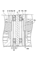
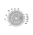
- FIG. 1 is a cross-sectional view illustrating the motor according to the first embodiment.
- the motor 1 is an axial flow fan motor having an impeller 10, a rotor shaft 20, a rolling bearing 30, a bearing housing 40, a stator 50, a rotor 60, and a casing 70.
- the impeller 10 has a rotor housing 11 and blades 12 provided on the outer periphery of the rotor housing 11.
- a rotor shaft 20 having a rotation axis m is fixed to the center of the impeller 10.
- the rotor shaft 20 is rotatably supported by two rolling bearings 30 arranged near both ends in the longitudinal direction.
- the rolling bearing 30 has an outer ring 31, an inner ring 32, and a plurality of rolling elements 33.
- the outer ring 31 is a cylindrical structure having a rotation axis m as a central axis.
- the inner ring 32 is a cylindrical structure arranged coaxially with the outer ring 31 on the inner peripheral side of the outer ring 31.
- Each of the plurality of rolling elements 33 is a sphere arranged in an orbit formed between the outer ring 31 and the inner ring 32.
- a lubricant such as grease is sealed in the track.
- the rolling bearing 30 is fixed to the bearing housing 40 by press fitting, adhesion, or the like, and is held in the bearing housing 40.
- the bearing housing 40 presses the outer peripheral surface of the outer ring 31 over the entire circumference.
- the bearing housing 40 can be formed of, for example, a metal such as brass.
- the stator 50 has an insulator 51, a stator core 52, and a coil 53, and is arranged on the outer periphery of the bearing housing 40.
- the stator core 52 is fixed to the outer periphery of the bearing housing 40 by press fitting or the like, for example.
- the rotor 60 has a rotor yoke 61 integrally provided inside the rotor housing 11, and a rotor magnet 62 mounted inside the rotor yoke 61.
- the rotor yoke 61 is integrally provided inside the rotor housing 11, but the present invention is not limited to this, and the rotor yoke 61 may be mounted inside the rotor housing 11.
- the rotor shaft 20 is mounted on the rotor yoke 61 and fixed to the center of the rotor housing 11, the rotor shaft 20 may be directly fixed to the rotor housing 11.
- the casing 70 has a casing outer frame 71 that covers the outer periphery of the impeller 10, a base hub 72 that fixes the bearing housing 40, and a stationary blade 73 that connects the casing outer frame 71 and the base hub 72. ..
- bearing housing 40 may be fixed so as to be integrated with the base portion hub 72 when the casing 70 is injection-molded with resin, but the casing 70 may be molded first and then the base portion hub. It may be fixed to the portion 72.
- the motor unit 80 is composed of the stator 50 and the rotor 60, and the rotor is rotatably supported in the bearing housing 40 by supplying a current from the power supply unit (not shown) to the coil 53.
- the impeller 10 rotates with the central axis of the shaft 20 as the rotation axis m. That is, the motor 1 is a so-called outer rotor type motor.
- the upper side in FIG. 1 is the suction port side, and the lower side is the outlet side. Therefore, in the motor 1, the impeller 10 is provided on the air suction port side of the casing outer frame 71, and the base portion hub 72 is provided on the blowout port side.
- FIG. 2 is a partially enlarged cross-sectional view of the vicinity of the rotor shaft of the motor according to the first embodiment.
- FIG. 3 is a partially enlarged plan view of a portion C in FIG.
- FIG. 4 is a partially enlarged perspective view of the outer peripheral portion of the bearing housing.
- the rolling bearing is shown in a simplified manner, and some members are not shown.
- the strain gauge 100 is fixed on the inner side in the radial direction (on the rotation axis m side) of the inner diameter of the stator core 52.
- the outer peripheral surface 40a of the bearing housing 40 that holds the rolling bearing 30 is provided with a recess 40x that is recessed on the rotation axis m side. Then, the strain gauge 100 is fixed to the recess 40x with an adhesive or the like.
- the inner diameter of the stator core 52 is a portion of the stator core 52 that is in contact with the outer peripheral surface 40a of the bearing housing 40.
- the recess 40x is provided in a part of the peripheral surface 40a of the bearing housing 40 in the circumferential direction.
- the recess 40x is not limited to the form shown in FIGS. 2 to 4.
- the recess 40x may reach the axial end of the outer peripheral surface 40a of the bearing housing 40.
- the recess 40x may be provided over the entire circumference of the outer peripheral surface 40a of the bearing housing 40.
- a recess 40x recessed on the rotation axis m side may be provided on the outer peripheral surface 40a of the bearing housing 40 of the portion holding the rolling bearing 30 arranged on the lower side.
- the recess 40x can be provided over the entire circumference of the outer peripheral surface 40a of the bearing housing 40.
- the recess 40x may be provided in a part of the outer peripheral surface 40a of the bearing housing 40 in the circumferential direction.
- the strain gauge 100 is a sensor provided with a resistor 103 for detecting the strain of the rolling bearing 30 (for example, the strain of the outer ring 31).
- the strain gauge 100 By arranging the strain gauge 100 in the recess 40x provided on the outer peripheral surface 40a of the bearing housing 40, the strain of the rolling bearing 30 is transmitted to the strain gauge 100 via the bearing housing 40 and can be detected by the strain gauge 100. .. In the present embodiment, the strain gauge 100 detects the strain of the rolling bearing 30 as a change in the resistance value of the resistor 103.
- the resistor 103 is arranged with the longitudinal direction (gauge length direction) facing the circumferential direction of the bearing housing 40. Since the circumferential direction of the bearing housing 40 is easier to expand and contract than the axial direction, a large strain waveform can be obtained by arranging the longitudinal direction of the resistor 103 toward the circumferential direction of the bearing housing 40.
- the strain gauge 100 has a pair of terminal portions 105 connected to both ends of the resistor 103 via the wiring 104, and the wiring 200 is electrically connected to each terminal portion 105 by solder or the like. ing.
- the wiring 200 is drawn out from the stator core 52 to the lower side in the axial direction, that is, to the outer side of the motor 1 through a notch 52x (recess for passing the wiring) provided on the inner circumference of the stator core 52.
- the notch 52x can be, for example, an elongated recess provided substantially parallel to the axis of rotation m.
- the wiring 200 electrically connected to the strain gauge 100 is pulled out axially downward from the stator core 52 through a notch 52x provided on the inner circumference of the stator core 52, and is outside the motor 1. It is pulled out directly to.
- the wiring 200 is not limited to this, and the wiring 200 electrically connected to the strain gauge 100 is pulled out axially lower than the stator core 52 through the notch 52x provided on the inner circumference of the stator core 52, and the motor. It may be electrically connected to the circuit board arranged inside 1. In this case, another wiring is drawn from the circuit board to the outside of the motor 1.
- the wiring 200 is interfered with by electromagnetic noise generated from the coil 53 and the like, it is preferable that at least a part of the wiring 200 is shielded. In the example shown in FIGS. 2 to 6, it is preferable that at least a portion of the wiring 200 passing through the notch 52x is shielded. In the example shown in FIG. 7, it is preferable that at least a portion of the wiring 200 passing through the inside of the motor 1 is shielded.
- the wiring 200 may be, for example, a coaxial cable, or may have a structure in which a solid GND is formed on at least one side of the flexible substrate.
- the bearing housing 40 to which the strain gauge 100 is fixed is preferably GND having the same potential as the shield portion of the wiring 200.
- the conductive adhesive include a paste in which particles such as silver, nickel, gold, copper, and carbon black are dispersed in the adhesive.
- the wiring 200 electrically connected to the strain gauge 100 is, for example, directly drawn out from the recess 40x to the outside of the motor 1, or is a circuit board arranged inside the motor 1. It is electrically connected. Therefore, in the case of FIG. 7, it is not necessary to provide the notch 52x on the inner circumference of the stator core 52.
- the strain gauge 100 is arranged radially inside the inner diameter of the stator core 52, which is a position where strain can be easily detected, even a slight strain can be detected. That is, if the outer ring 31 of the rolling bearing 30 is slightly distorted, the bearing housing 40 is also distorted. Therefore, this slight strain is applied by the strain gauge 100 fixed to the recess 40x provided on the outer peripheral surface 40a of the bearing housing 40. Can be detected.
- the state of the rolling bearing 30 can be monitored by, for example, FFT analysis (fast Fourier transform) of the strain waveform obtained between the terminal portions 105 of the strain gauge 100. Therefore, by monitoring the change in the strain waveform, it is possible to detect the abnormality of the rolling bearing 30 and detect the abnormality before the motor 1 causes a rotation failure.
- FFT analysis fast Fourier transform
- an axial fan motor used for cooling a server is always in operation, and if it is stopped even temporarily, the cooling capacity is lowered. In this case, it is particularly effective to monitor the state of the rolling bearing 30 because it is desired to detect the abnormality of the axial fan motor as soon as possible.
- the strain gauge 100 is fixed to the recess 40x provided on the outer peripheral surface 40a of the bearing housing 40, and the strain gauge 100 does not protrude outside the outer peripheral surface 40a. Therefore, after fixing the strain gauge 100 to the bearing housing 40, it is possible to press-fit the stator core 52 into the outer periphery of the bearing housing 40. At this time, the inner peripheral surface of the stator core 52 and the strain gauge 100 do not interfere with each other.
- the wiring 200 is passed through a notch 52x formed on the inner circumference of the stator core 52.
- the wiring 200 is passed through the notch 52x formed on the inner circumference of the stator core 52, and the portion of the wiring 200 passing through at least the notch 52x is shielded.
- the influence of electromagnetic noise can be significantly suppressed as compared with the case where the wiring 200 is passed through the outside of the stator core 52 (comparative example of FIG. 9).
- the accuracy of abnormality detection of the rolling bearing 30 can be improved.
- FIG. 8 is an example of a waveform obtained based on the output of the strain gauge 100.
- the wiring 200 is passed through the notch 52x formed on the inner circumference of the stator core 52, and at least the notch 52x of the wiring 200 is passed through the notch 52x. It is a waveform when the passing part is shielded.
- FIG. 9 is a comparative example, and is a waveform when the wiring 200 is passed through the outside of the stator core 52 in the motor 1.
- the waveform obtained based on the output of the strain gauge 100 has a peak strain amount (output intensity) when the rolling element 33 passes directly under the resistor 103 of the strain gauge 100, and is an intermediate point of the adjacent rolling elements 33. Becomes the bottom and becomes a periodic waveform that repeats the peak and bottom. In FIG. 8, it can be confirmed that a periodic strain waveform that repeats peaks and bottoms is obtained without being buried in electromagnetic noise. On the other hand, in FIG. 9, the electromagnetic noise is large and the correct distortion waveform is not obtained.
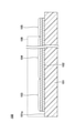
- FIG. 10 is a plan view illustrating the strain gauge according to the first embodiment.
- FIG. 11 is a cross-sectional view illustrating the strain gauge according to the first embodiment, and shows a cross-sectional view taken along the line AA of FIG.
- the strain gauge 100 has a base material 101, a functional layer 102, a resistor 103, a wiring 104, and a terminal portion 105.
- the functional layer 102 may be provided as needed.
- the side of the base material 101 where the resistor 103 is provided is the upper side or one side, and the side where the resistor 103 is not provided is the lower side or the other side.
- the surface on the side where the resistor 103 is provided at each portion is defined as one surface or the upper surface, and the surface on the side where the resistor 103 is not provided is defined as the other surface or the lower surface.
- the strain gauge 100 can be used in an upside-down state, or can be arranged at an arbitrary angle.
- the plan view refers to viewing the object from the normal direction of the upper surface 101a of the base material 101
- the planar shape refers to the shape of the object viewed from the normal direction of the upper surface 101a of the base material 101.
- the base material 101 is a member that serves as a base layer for forming the resistor 103 and the like, and has flexibility.
- the thickness of the base material 101 is not particularly limited and may be appropriately selected depending on the intended purpose, but may be, for example, about 5 ⁇ m to 500 ⁇ m. In particular, when the thickness of the base material 101 is 5 ⁇ m to 200 ⁇ m, the strain from the strain-causing surface (for example, the outer peripheral surface 40a of the bearing housing 40) bonded to the lower surface of the base material 101 via the adhesive layer 150 is strained. It is preferable from the viewpoint of transmissibility and dimensional stability to the environment, and more preferably 10 ⁇ m or more is further preferable from the viewpoint of insulating property.
- the base material 101 is, for example, PI (polyethylene) resin, epoxy resin, PEEK (polyetheretherketone) resin, PEN (polyethylenenaphthalate) resin, PET (polyethylene terephthalate) resin, PPS (polyphenylene sulfide) resin, polyolefin resin and the like. It can be formed from the insulating resin film of.
- the film is a member having a thickness of about 500 ⁇ m or less and having flexibility.
- the base material 101 may be formed of, for example, an insulating resin film containing a filler such as silica or alumina.
- Materials other than the resin of the base material 101 include, for example, SiO 2 , ZrO 2 (including YSZ), Si, Si 2 N 3 , Al 2 O 3 (including sapphire), ZnO, and perovskite ceramics (CaTIO 3 ,). Crystalline materials such as BaTIO 3 ) can be mentioned, and amorphous glass and the like can be mentioned in addition to the above. Further, as the material of the base material 101, a metal such as aluminum, an aluminum alloy (duralumin), or titanium may be used. In this case, for example, an insulating film is formed on the metal base material 101.
- the functional layer 102 is formed on the upper surface 101a of the base material 101 as a lower layer of the resistor 103. That is, the planar shape of the functional layer 102 is substantially the same as the planar shape of the resistor 103 shown in FIG.
- the functional layer refers to a layer having at least a function of promoting crystal growth of the resistor 103, which is an upper layer. It is preferable that the functional layer 102 further has a function of preventing oxidation of the resistor 103 due to oxygen and moisture contained in the base material 101 and a function of improving the adhesion between the base material 101 and the resistor 103. ..
- the functional layer 102 may further have other functions.
- the insulating resin film constituting the base material 101 contains oxygen and water, particularly when the resistor 103 contains Cr (chromium), Cr forms a self-oxidizing film, so that the functional layer 102 oxidizes the resistor 103. It is effective to have a function to prevent it.
- the material of the functional layer 102 is not particularly limited as long as it has a function of promoting crystal growth of the resistor 103, which is at least the upper layer, and can be appropriately selected depending on the intended purpose.
- Cr chromium
- Ti. Ti.
- V vanadium
- Nb Niobium
- Ta Ta
- Ti Ni
- Zr Zyryl
- Hf Hafnium
- Si Si
- C Carbon
- Zn Zinc
- Cu Copper
- Bi Bi
- Fe Iron
- Mo Mo
- W Tungsten
- Ru Litenium
- Examples of the above alloy include FeCr, TiAl, FeNi, NiCr, CrCu and the like.
- Examples of the above -mentioned compound include TiN, TaN, Si 3N 4, TiO 2, Ta 2 O 5, SiO 2 , and the like .
- the film thickness of the functional layer 102 is preferably 1/20 or less of the film thickness of the resistor. Within such a range, the crystal growth of ⁇ -Cr can be promoted, and a part of the current flowing through the resistor can be prevented from flowing to the functional layer 102 to reduce the strain detection sensitivity.
- the film thickness of the functional layer 102 is more preferably 1/50 or less of the film thickness of the resistor. Within such a range, the crystal growth of ⁇ -Cr can be promoted, and a part of the current flowing through the resistor can be prevented from flowing to the functional layer 102 to further prevent the strain detection sensitivity from being lowered.
- the film thickness of the functional layer 102 is more preferably 1/100 or less of the film thickness of the resistor. Within such a range, it is possible to further prevent a part of the current flowing through the resistor from flowing to the functional layer 102 and reducing the strain detection sensitivity.
- the film thickness of the functional layer 102 is preferably 1 nm to 1 ⁇ m. Within such a range, the crystal growth of ⁇ -Cr can be promoted, and the functional layer 102 can be easily formed without cracks.
- the film thickness of the functional layer 102 is more preferably 1 nm to 0.8 ⁇ m. Within such a range, the crystal growth of ⁇ -Cr can be promoted, and the functional layer 102 can be more easily formed without cracks.
- the film thickness of the functional layer 102 is more preferably 1 nm to 0.5 ⁇ m. Within such a range, the crystal growth of ⁇ -Cr can be promoted, and the functional layer 102 can be more easily formed without cracks.
- the planar shape of the functional layer 102 is patterned substantially the same as the planar shape of the resistor shown in FIG. 10, for example.
- the planar shape of the functional layer 102 is not limited to the case where it is substantially the same as the planar shape of the resistor.
- the functional layer 102 may be formed in a solid shape at least in the region where the resistor is formed.
- the functional layer 102 may be formed in a solid shape on the entire upper surface of the base material 101.
- the thickness of the functional layer 102 is formed relatively thick so that the thickness of the functional layer 102 is 50 nm or more and 1 ⁇ m or less, and the functional layer 102 is formed in a solid shape. Since the surface area is increased, the heat generated when the resistor generates heat can be dissipated to the base material 101 side. As a result, in the strain gauge 100, it is possible to suppress a decrease in measurement accuracy due to self-heating of the resistor.
- the resistor 103 is a thin film formed on the upper surface of the functional layer 102 in a predetermined pattern, and is a sensitive portion that undergoes strain to cause a change in resistance.
- the resistor 103 can be formed from, for example, a material containing Cr (chromium), a material containing Ni (nickel), or a material containing both Cr and Ni. That is, the resistor 103 can be formed from a material containing at least one of Cr and Ni. Examples of the material containing Cr include a Cr mixed phase film. Examples of the material containing Ni include Cu—Ni (copper nickel). Examples of the material containing both Cr and Ni include Ni—Cr (nickel chromium).
- the Cr mixed phase film is a film in which Cr, CrN, Cr 2N and the like are mixed.
- the Cr mixed phase film may contain unavoidable impurities such as chromium oxide. Further, a part of the material constituting the functional layer 102 may be diffused in the Cr mixed phase film. In this case, the material constituting the functional layer 102 and nitrogen may form a compound.
- the Cr mixed phase film may contain Ti or TiN (titanium nitride).
- the thickness of the resistor 103 is not particularly limited and can be appropriately selected depending on the purpose, but can be, for example, about 0.05 ⁇ m to 2 ⁇ m.
- the thickness of the resistor 103 is 0.1 ⁇ m or more, the crystallinity of the crystals constituting the resistor 103 (for example, the crystallinity of ⁇ -Cr) is improved, and when the thickness is 1 ⁇ m or less, the resistor is preferable. It is more preferable in that it can reduce cracks in the film and warpage from the base material 101 due to the internal stress of the film constituting 103.
- the resistor 103 By forming the resistor 103 on the functional layer 102, the resistor 103 can be formed with a stable crystal phase, so that the stability of the gauge characteristics (gauge ratio, gauge coefficient temperature coefficient TCS, and resistance temperature coefficient TCR) is improved. can.
- the resistor 103 when the resistor 103 is a Cr mixed phase film, the resistor 103 containing ⁇ -Cr (alpha chromium) as a main component can be formed by providing the functional layer 102. Since ⁇ -Cr is a stable crystal phase, the stability of gauge characteristics can be improved.
- ⁇ -Cr alpha chromium
- the main component means that the target substance occupies 50% by mass or more of all the substances constituting the resistor.
- the resistor 103 is a Cr mixed film
- the resistor 103 preferably contains 80% by weight or more of ⁇ -Cr, and more preferably 90% by weight or more, from the viewpoint of improving the gauge characteristics.
- ⁇ -Cr is Cr of a bcc structure (body-centered cubic lattice structure).
- the Cr N and Cr 2 N contained in the Cr mixed film are preferably 20% by weight or less.
- Cr N and Cr 2 N contained in the Cr mixed phase film are 20% by weight or less, a decrease in the gauge ratio can be suppressed.
- the ratio of Cr 2N in Cr N and Cr 2N is preferably 80% by weight or more and less than 90% by weight, and more preferably 90% by weight or more and less than 95% by weight.
- the ratio of Cr 2 N in Cr N and Cr 2 N is 90% by weight or more and less than 95% by weight, the decrease in TCR (negative TCR) becomes more remarkable due to Cr 2 N having semiconducting properties. .. Further, by reducing the use of ceramics, brittle fracture is reduced.
- the gauge characteristics can be improved by diffusing the metal (for example, Ti) constituting the functional layer 102 into the Cr mixed phase film.
- the gauge ratio of the strain gauge 100 can be 10 or more, and the gauge ratio temperature coefficient TCS and the resistance temperature coefficient TCR can be in the range of ⁇ 1000 ppm / ° C. to + 1000 ppm / ° C.
- the terminal portion 105 extends from both ends of the resistor 103 via the wiring 104, and is wider than the resistor 103 and the wiring 104 in a plan view and is formed in a substantially rectangular shape.
- the terminal portion 105 is a pair of electrodes for outputting a change in the resistance value of the resistor 103 caused by strain to the outside.
- the resistor 103 extends from one of the terminal portion 105 and the wiring 104 while being folded back in a zigzag manner, and is connected to the other wiring 104 and the terminal portion 105, for example.
- the upper surface of the terminal portion 105 may be coated with a metal having better solderability than the terminal portion 105.
- the resistor 103, the wiring 104, and the terminal portion 105 are designated by different codes for convenience, they can be integrally formed of the same material in the same process.
- a cover layer 106 (insulating resin layer) may be provided on the upper surface 101a of the base material 101 so as to cover the resistor 103 and the wiring 104 and expose the terminal portion 105.
- the cover layer 106 may be provided so as to cover the entire portion excluding the terminal portion 105.
- the cover layer 106 can be formed of, for example, an insulating resin such as PI resin, epoxy resin, PEEK resin, PEN resin, PET resin, PPS resin, and composite resin (for example, silicone resin and polyolefin resin).
- the cover layer may contain a filler or a pigment.
- the thickness of the cover layer is not particularly limited and may be appropriately selected depending on the intended purpose, but may be, for example, about 2 ⁇ m to 30 ⁇ m.
- the base material 101 is prepared, and the functional layer 102 is formed on the upper surface 101a of the base material 101.
- the materials and thicknesses of the base material 101 and the functional layer 102 are as described above. However, the functional layer 102 may be provided as needed.
- the functional layer 102 can be formed into a vacuum by, for example, a conventional sputtering method in which Ar (argon) gas is introduced into a chamber, targeting a raw material capable of forming the functional layer 102.
- Ar argon
- the functional layer 102 is formed while etching the upper surface 101a of the base material 101 with Ar, so that the film forming amount of the functional layer 102 can be minimized and the adhesion improving effect can be obtained. can.
- the functional layer 102 may be formed by another method.
- the adhesion improving effect is obtained by activating the upper surface 101a of the base material 101 by plasma treatment using Ar or the like before the film formation of the functional layer 102, and then the functional layer 102 is evacuated by the magnetron sputtering method.
- a method of forming a film may be used.
- the functional layer 102 and the resistor 103, the wiring 104, and the terminal portion 105 are shown in FIG. 10 by photolithography. Patterning is performed in the plane shape shown in.
- the materials and thicknesses of the resistor 103, the wiring 104, and the terminal portion 105 are as described above.
- the resistor 103, the wiring 104, and the terminal portion 105 can be integrally formed of the same material.
- the resistor 103, the wiring 104, and the terminal portion 105 can be formed into a film by, for example, a magnetron sputtering method targeting a raw material capable of forming the resistor 103, the wiring 104, and the terminal portion 105.
- the resistor 103, the wiring 104, and the terminal portion 105 may be formed into a film by a reactive sputtering method, a vapor deposition method, an arc ion plating method, a pulse laser deposition method, or the like, instead of the magnetron sputtering method.
- the combination of the material of the functional layer 102 and the material of the resistor 103, the wiring 104, and the terminal portion 105 is not particularly limited and may be appropriately selected depending on the intended purpose.
- Ti is used as the functional layer 102 and the resistor is used.
- a Cr mixed-phase film containing ⁇ -Cr (alpha chromium) as a main component can be formed as the 103, the wiring 104, and the terminal portion 105.
- the resistor 103, the wiring 104, and the terminal portion 105 can be formed into a film by a magnetron sputtering method in which Ar gas is introduced into the chamber, targeting a raw material capable of forming a Cr mixed-phase film.
- Ar gas is introduced into the chamber, targeting a raw material capable of forming a Cr mixed-phase film.
- pure Cr may be targeted, an appropriate amount of nitrogen gas may be introduced into the chamber together with Ar gas, and the resistor 103, the wiring 104, and the terminal portion 105 may be formed into a film by the reactive sputtering method.
- the growth surface of the Cr mixed-phase film is defined by the functional layer 102 made of Ti, and a Cr mixed-phase film containing ⁇ -Cr as a main component, which has a stable crystal structure, can be formed.
- the gauge characteristics are improved by diffusing Ti constituting the functional layer 102 in the Cr mixed phase film.
- the gauge ratio of the strain gauge 100 can be 10 or more, and the gauge ratio temperature coefficient TCS and the resistance temperature coefficient TCR can be in the range of ⁇ 1000 ppm / ° C. to + 1000 ppm / ° C.
- the functional layer 102 made of Ti has a function of promoting crystal growth of the resistor 103 and prevents oxidation of the resistor 103 by oxygen or moisture contained in the substrate 101. It has all the functions and the function of improving the adhesion between the base material 101 and the resistor 103. The same applies when Ta, Si, Al, or Fe is used as the functional layer 102 instead of Ti.
- the strain gauge 100 is completed by providing a cover layer 106 that covers the resistor 103 and the wiring 104 and exposes the terminal portion 105 on the upper surface 101a of the base material 101.
- the cover layer 106 is, for example, laminated with a semi-curable thermosetting insulating resin film on the upper surface 101a of the base material 101 so as to cover the resistor 103 and the wiring 104 and expose the terminal portion 105, and heat the cover layer 106. Can be produced by curing.
- the cover layer 106 is coated with a resistor 103 and a wiring 104 on the upper surface 101a of the base material 101, and a liquid or paste-like thermosetting insulating resin is applied so as to expose the terminal portion 105, and the cover layer 106 is heated and cured. May be produced.
- the functional layer 102 under the resistor 103 By providing the functional layer 102 under the resistor 103 in this way, the crystal growth of the resistor 103 can be promoted, and the resistor 103 having a stable crystal phase can be produced. As a result, the stability of the gauge characteristics can be improved in the strain gauge 100. Further, the material constituting the functional layer 102 diffuses into the resistor 103, so that the gauge characteristics of the strain gauge 100 can be improved.
- the strain gauge 100 using a Cr mixed phase film as the material of the resistor 103 has achieved high sensitivity (500% or more compared to the conventional method) and miniaturization (1/10 or less compared to the conventional method). For example, while the output of the conventional strain gauge is about 0.04 mV / 2V, the strain gauge 100 can obtain an output of 0.3 mV / 2 V or more. Further, the size of the strain gauge 100 (gauge length x gauge width) is 0.3 mm x 0.3 mm, whereas the size of the conventional strain gauge (gauge length x gauge width) is about 3 mm x 3 mm. It can be downsized to some extent.
- the strain gauge 100 using the Cr mixed film as the material of the resistor 103 is small and can be easily attached to the recess 40x provided on the outer peripheral surface 40a of the bearing housing 40. Therefore, it is particularly suitable for use in a motor 1 using a small rolling bearing 30 having a diameter (outer diameter of the outer ring 31) of 30 mm or less. Further, since the strain gauge 100 using the Cr mixed phase film as the material of the resistor 103 has high sensitivity and can detect a small displacement, it is possible to detect a minute strain which was difficult to detect in the past. That is, by having the strain gauge 100 using the Cr mixed phase film as the material of the resistor 103, it is possible to realize the motor 1 having a function of accurately detecting the strain.
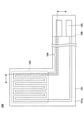
- FIG. 12 is a partially enlarged cross-sectional view of the vicinity of the rotor shaft of the motor according to the second embodiment.
- FIG. 13 is a partially enlarged plan view of a portion D in FIG. In FIG. 13, the rolling bearing is shown in a simplified manner, and some members are not shown.
- the strain gauge 100 is fixed on the inner side in the radial direction (on the rotation axis m side) of the inner diameter of the stator core 52. Specifically, the strain gauge 100 is fixed to the outer peripheral surface 31a of the outer ring 31 via an adhesive layer.
- the inner peripheral surface 40b of the bearing housing 40 facing the strain gauge 100 in the radial direction is provided with a recess 40y for preventing interference with the strain gauge 100. That is, the strain gauge 100 is fixed to the outer peripheral surface 31a of the outer ring 31 facing the recess 40y provided on the inner peripheral surface 40b of the bearing housing 40.
- the recess 40y may be provided in a part of the inner peripheral surface 40b of the bearing housing 40 in the circumferential direction, or may be provided over the entire circumference of the inner peripheral surface 40b of the bearing housing 40.
- the inner peripheral surface 40b of the bearing housing 40 and the strain gauge 100 do not interfere with each other when the rolling bearing 30 is attached to the inner peripheral surface 40b of the bearing housing 40. .. Further, the inner peripheral surface 40b of the bearing housing 40 axially below the recess y is fitted in a gap with the rolling bearing 30.
- the wiring 200 goes around the upper end in the axial direction of the bearing housing 40, enters the notch 52x formed on the inner circumference of the stator core 52, passes through the notch 52x, and is axially lower than the stator core 52, that is, on the outer side of the motor 1. It has been pulled out.
- the wiring 200 electrically connected to the strain gauge 100 is pulled out axially downward from the stator core 52 through a notch 52x provided on the inner circumference of the stator core 52, and is outside the motor 1. It is pulled out directly to.
- the wiring 200 is not limited to this, and the wiring 200 electrically connected to the strain gauge 100 is pulled out axially lower than the stator core 52 through the notch 52x provided on the inner circumference of the stator core 52, and the motor. It may be electrically connected to the circuit board arranged inside 1. In this case, another wiring is drawn from the circuit board to the outside of the motor 1.
- the wiring 200 is shielded from at least a portion passing through the notch 52x because it is interfered with by electromagnetic noise generated from the coil 53 and the like.
- the wiring 200 may be, for example, a coaxial cable, or may have a structure in which a solid GND is formed on at least one side of the flexible substrate. From the viewpoint of suppressing the influence of electromagnetic noise, it is preferable that the outer ring 31 has a GND having the same potential as the shield portion of the wiring 200.
- the strain gauge 100 may be fixed to the outer peripheral surface 31a of the outer ring 31.
- the outer peripheral surface 31a of the outer ring 31 is at a position where strain can be easily detected, even a slight strain can be detected. That is, when the outer ring 31 of the rolling bearing 30 is slightly distorted, this slight strain can be detected by the strain gauge 100 fixed to the outer peripheral surface 31a of the outer ring 31.
- the inner peripheral surface of the bearing housing 40 is provided with the recess 40y on the inner peripheral surface 40b of the bearing housing 40 that faces the strain gauge 100 in the radial direction. Interference between 40b and the strain gauge 100 can be prevented.
- the influence of electromagnetic noise is affected as in the first embodiment. It can be significantly suppressed.
- the axial fan motor is exemplified as the motor, but the present invention is not limited to this, and the present invention can be widely applied to motors other than the axial fan motor.
- strain gauges are provided on the rolling bearings arranged on the upper side or the rolling bearings arranged on the lower side in FIG. 1 and the like is shown, but strain gauges are provided on both rolling bearings. May be good. Further, a plurality of strain gauges may be provided on one or both of the rolling bearing arranged on the upper side and the rolling bearing arranged on the lower side in FIG. 1 and the like.
Landscapes
- Engineering & Computer Science (AREA)
- General Engineering & Computer Science (AREA)
- Mechanical Engineering (AREA)
- Power Engineering (AREA)
- Rolling Contact Bearings (AREA)
- Motor Or Generator Frames (AREA)
- Measurement Of Length, Angles, Or The Like Using Electric Or Magnetic Means (AREA)
Priority Applications (1)
| Application Number | Priority Date | Filing Date | Title |
|---|---|---|---|
| JP2022512460A JP7261938B2 (ja) | 2020-07-31 | 2021-07-27 | モータ |
Applications Claiming Priority (2)
| Application Number | Priority Date | Filing Date | Title |
|---|---|---|---|
| JP2020-131004 | 2020-07-31 | ||
| JP2020131004 | 2020-07-31 |
Publications (1)
| Publication Number | Publication Date |
|---|---|
| WO2022025075A1 true WO2022025075A1 (ja) | 2022-02-03 |
Family
ID=80036599
Family Applications (1)
| Application Number | Title | Priority Date | Filing Date |
|---|---|---|---|
| PCT/JP2021/027787 Ceased WO2022025075A1 (ja) | 2020-07-31 | 2021-07-27 | モータ |
Country Status (2)
| Country | Link |
|---|---|
| JP (1) | JP7261938B2 (https=) |
| WO (1) | WO2022025075A1 (https=) |
Citations (4)
| Publication number | Priority date | Publication date | Assignee | Title |
|---|---|---|---|---|
| JP2017096445A (ja) * | 2015-11-26 | 2017-06-01 | 日本精工株式会社 | センサ付き転がり軸受 |
| JP2019070570A (ja) * | 2017-10-10 | 2019-05-09 | 日本精工株式会社 | 転がり軸受の異常診断装置 |
| JP2019161745A (ja) * | 2018-03-08 | 2019-09-19 | ミネベアミツミ株式会社 | モータ |
| JP2019219313A (ja) * | 2018-06-21 | 2019-12-26 | ミネベアミツミ株式会社 | センサモジュール |
Family Cites Families (1)
| Publication number | Priority date | Publication date | Assignee | Title |
|---|---|---|---|---|
| JPH02164241A (ja) * | 1989-10-18 | 1990-06-25 | Fuji Electric Co Ltd | アンギュラコンタクト形組合わせ玉軸受の予圧量検出装置 |
-
2021
- 2021-07-27 JP JP2022512460A patent/JP7261938B2/ja active Active
- 2021-07-27 WO PCT/JP2021/027787 patent/WO2022025075A1/ja not_active Ceased
Patent Citations (4)
| Publication number | Priority date | Publication date | Assignee | Title |
|---|---|---|---|---|
| JP2017096445A (ja) * | 2015-11-26 | 2017-06-01 | 日本精工株式会社 | センサ付き転がり軸受 |
| JP2019070570A (ja) * | 2017-10-10 | 2019-05-09 | 日本精工株式会社 | 転がり軸受の異常診断装置 |
| JP2019161745A (ja) * | 2018-03-08 | 2019-09-19 | ミネベアミツミ株式会社 | モータ |
| JP2019219313A (ja) * | 2018-06-21 | 2019-12-26 | ミネベアミツミ株式会社 | センサモジュール |
Also Published As
| Publication number | Publication date |
|---|---|
| JPWO2022025075A1 (https=) | 2022-02-03 |
| JP7261938B2 (ja) | 2023-04-20 |
Similar Documents
| Publication | Publication Date | Title |
|---|---|---|
| JP6986050B2 (ja) | 軸受監視装置、軸受監視方法 | |
| JP2024177526A (ja) | ひずみゲージ | |
| WO2022075157A1 (ja) | モータ | |
| WO2022025075A1 (ja) | モータ | |
| JP7261937B2 (ja) | モータ | |
| JP2025142294A (ja) | ひずみゲージ | |
| JP7712031B2 (ja) | 転がり軸受ホルダユニット | |
| US12331787B2 (en) | Rolling bearing, rotating apparatus, bearing monitoring apparatus and method for monitoring bearing | |
| JP7317245B2 (ja) | 転がり軸受 | |
| JP2023107679A (ja) | 軸受装置、モータ、ひずみ検出装置 | |
| JP2023141894A (ja) | センサユニット、軸受装置、ひずみ検出装置、モータ | |
| JP2023141893A (ja) | センサユニット、軸受装置、ひずみ検出装置、モータ | |
| JP2023166819A (ja) | 軸受装置、ひずみ検出装置 | |
| JP2022013146A (ja) | 転がり軸受 | |
| US12613088B2 (en) | Strain gauge including barrier layer over resistor body | |
| JP2023176571A (ja) | 軸受装置 |
Legal Events
| Date | Code | Title | Description |
|---|---|---|---|
| ENP | Entry into the national phase |
Ref document number: 2022512460 Country of ref document: JP Kind code of ref document: A |
|
| 121 | Ep: the epo has been informed by wipo that ep was designated in this application |
Ref document number: 21848888 Country of ref document: EP Kind code of ref document: A1 |
|
| NENP | Non-entry into the national phase |
Ref country code: DE |
|
| 122 | Ep: pct application non-entry in european phase |
Ref document number: 21848888 Country of ref document: EP Kind code of ref document: A1 |