WO2022025075A1 - Motor - Google Patents
Motor Download PDFInfo
- Publication number
- WO2022025075A1 WO2022025075A1 PCT/JP2021/027787 JP2021027787W WO2022025075A1 WO 2022025075 A1 WO2022025075 A1 WO 2022025075A1 JP 2021027787 W JP2021027787 W JP 2021027787W WO 2022025075 A1 WO2022025075 A1 WO 2022025075A1
- Authority
- WO
- WIPO (PCT)
- Prior art keywords
- resistor
- strain gauge
- wiring
- bearing housing
- functional layer
- Prior art date
Links
Images


Classifications
-
- F—MECHANICAL ENGINEERING; LIGHTING; HEATING; WEAPONS; BLASTING
- F16—ENGINEERING ELEMENTS AND UNITS; GENERAL MEASURES FOR PRODUCING AND MAINTAINING EFFECTIVE FUNCTIONING OF MACHINES OR INSTALLATIONS; THERMAL INSULATION IN GENERAL
- F16C—SHAFTS; FLEXIBLE SHAFTS; ELEMENTS OR CRANKSHAFT MECHANISMS; ROTARY BODIES OTHER THAN GEARING ELEMENTS; BEARINGS
- F16C19/00—Bearings with rolling contact, for exclusively rotary movement
- F16C19/02—Bearings with rolling contact, for exclusively rotary movement with bearing balls essentially of the same size in one or more circular rows
- F16C19/04—Bearings with rolling contact, for exclusively rotary movement with bearing balls essentially of the same size in one or more circular rows for radial load mainly
- F16C19/06—Bearings with rolling contact, for exclusively rotary movement with bearing balls essentially of the same size in one or more circular rows for radial load mainly with a single row or balls
-
- H—ELECTRICITY
- H02—GENERATION; CONVERSION OR DISTRIBUTION OF ELECTRIC POWER
- H02K—DYNAMO-ELECTRIC MACHINES
- H02K5/00—Casings; Enclosures; Supports
- H02K5/04—Casings or enclosures characterised by the shape, form or construction thereof
- H02K5/16—Means for supporting bearings, e.g. insulating supports or means for fitting bearings in the bearing-shields
- H02K5/173—Means for supporting bearings, e.g. insulating supports or means for fitting bearings in the bearing-shields using bearings with rolling contact, e.g. ball bearings
Definitions
- the present invention relates to a motor.
- the sphere in the rolling bearing rotates and gives a slight strain to the rolling bearing.
- the strain of a rolling bearing changes depending on the state inside the rolling bearing. For example, when wear debris is generated inside a rolling bearing and adheres to a sphere or a rolling surface, the adhered material pushes up the outer ring and the amplitude of the outer ring increases. Further, when the wear of the sphere and the rolling surface progresses, the surface pressure between the sphere and the rolling surface decreases, and the amplitude of the outer ring becomes small.
- the strain generated in the rolling bearing is small, it is important where to place the sensor.
- a strain gauge is used as a sensor, it is necessary to arrange the strain gauge at a position where it can sufficiently detect the slight strain generated in the rolling bearing, but it is not easy to secure a space for arranging the strain gauge in the motor. There wasn't.
- the present invention has been made in view of the above points, and an object of the present invention is to provide a motor in which a strain gauge is arranged at a position where strain can be easily detected.
- This motor includes a rolling bearing that supports the rotor shaft in a rotatable state, a bearing housing that holds the rolling bearing, a stator core fixed to the outer periphery of the bearing housing, and a resistor that detects strain in the rolling bearing.
- the strain gauge is fixed to the inside in the radial direction with respect to the inner diameter of the stator core.
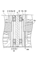
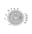
- FIG. 1 is a cross-sectional view illustrating the motor according to the first embodiment.
- the motor 1 is an axial flow fan motor having an impeller 10, a rotor shaft 20, a rolling bearing 30, a bearing housing 40, a stator 50, a rotor 60, and a casing 70.
- the impeller 10 has a rotor housing 11 and blades 12 provided on the outer periphery of the rotor housing 11.
- a rotor shaft 20 having a rotation axis m is fixed to the center of the impeller 10.
- the rotor shaft 20 is rotatably supported by two rolling bearings 30 arranged near both ends in the longitudinal direction.
- the rolling bearing 30 has an outer ring 31, an inner ring 32, and a plurality of rolling elements 33.
- the outer ring 31 is a cylindrical structure having a rotation axis m as a central axis.
- the inner ring 32 is a cylindrical structure arranged coaxially with the outer ring 31 on the inner peripheral side of the outer ring 31.
- Each of the plurality of rolling elements 33 is a sphere arranged in an orbit formed between the outer ring 31 and the inner ring 32.
- a lubricant such as grease is sealed in the track.
- the rolling bearing 30 is fixed to the bearing housing 40 by press fitting, adhesion, or the like, and is held in the bearing housing 40.
- the bearing housing 40 presses the outer peripheral surface of the outer ring 31 over the entire circumference.
- the bearing housing 40 can be formed of, for example, a metal such as brass.
- the stator 50 has an insulator 51, a stator core 52, and a coil 53, and is arranged on the outer periphery of the bearing housing 40.
- the stator core 52 is fixed to the outer periphery of the bearing housing 40 by press fitting or the like, for example.
- the rotor 60 has a rotor yoke 61 integrally provided inside the rotor housing 11, and a rotor magnet 62 mounted inside the rotor yoke 61.
- the rotor yoke 61 is integrally provided inside the rotor housing 11, but the present invention is not limited to this, and the rotor yoke 61 may be mounted inside the rotor housing 11.
- the rotor shaft 20 is mounted on the rotor yoke 61 and fixed to the center of the rotor housing 11, the rotor shaft 20 may be directly fixed to the rotor housing 11.
- the casing 70 has a casing outer frame 71 that covers the outer periphery of the impeller 10, a base hub 72 that fixes the bearing housing 40, and a stationary blade 73 that connects the casing outer frame 71 and the base hub 72. ..
- bearing housing 40 may be fixed so as to be integrated with the base portion hub 72 when the casing 70 is injection-molded with resin, but the casing 70 may be molded first and then the base portion hub. It may be fixed to the portion 72.
- the motor unit 80 is composed of the stator 50 and the rotor 60, and the rotor is rotatably supported in the bearing housing 40 by supplying a current from the power supply unit (not shown) to the coil 53.
- the impeller 10 rotates with the central axis of the shaft 20 as the rotation axis m. That is, the motor 1 is a so-called outer rotor type motor.
- the upper side in FIG. 1 is the suction port side, and the lower side is the outlet side. Therefore, in the motor 1, the impeller 10 is provided on the air suction port side of the casing outer frame 71, and the base portion hub 72 is provided on the blowout port side.
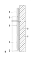
- FIG. 2 is a partially enlarged cross-sectional view of the vicinity of the rotor shaft of the motor according to the first embodiment.
- FIG. 3 is a partially enlarged plan view of a portion C in FIG.
- FIG. 4 is a partially enlarged perspective view of the outer peripheral portion of the bearing housing.
- the rolling bearing is shown in a simplified manner, and some members are not shown.
- the strain gauge 100 is fixed on the inner side in the radial direction (on the rotation axis m side) of the inner diameter of the stator core 52.
- the outer peripheral surface 40a of the bearing housing 40 that holds the rolling bearing 30 is provided with a recess 40x that is recessed on the rotation axis m side. Then, the strain gauge 100 is fixed to the recess 40x with an adhesive or the like.
- the inner diameter of the stator core 52 is a portion of the stator core 52 that is in contact with the outer peripheral surface 40a of the bearing housing 40.
- the recess 40x is provided in a part of the peripheral surface 40a of the bearing housing 40 in the circumferential direction.
- the recess 40x is not limited to the form shown in FIGS. 2 to 4.
- the recess 40x may reach the axial end of the outer peripheral surface 40a of the bearing housing 40.
- the recess 40x may be provided over the entire circumference of the outer peripheral surface 40a of the bearing housing 40.
- a recess 40x recessed on the rotation axis m side may be provided on the outer peripheral surface 40a of the bearing housing 40 of the portion holding the rolling bearing 30 arranged on the lower side.
- the recess 40x can be provided over the entire circumference of the outer peripheral surface 40a of the bearing housing 40.
- the recess 40x may be provided in a part of the outer peripheral surface 40a of the bearing housing 40 in the circumferential direction.
- the strain gauge 100 is a sensor provided with a resistor 103 for detecting the strain of the rolling bearing 30 (for example, the strain of the outer ring 31).
- the strain gauge 100 By arranging the strain gauge 100 in the recess 40x provided on the outer peripheral surface 40a of the bearing housing 40, the strain of the rolling bearing 30 is transmitted to the strain gauge 100 via the bearing housing 40 and can be detected by the strain gauge 100. .. In the present embodiment, the strain gauge 100 detects the strain of the rolling bearing 30 as a change in the resistance value of the resistor 103.
- the resistor 103 is arranged with the longitudinal direction (gauge length direction) facing the circumferential direction of the bearing housing 40. Since the circumferential direction of the bearing housing 40 is easier to expand and contract than the axial direction, a large strain waveform can be obtained by arranging the longitudinal direction of the resistor 103 toward the circumferential direction of the bearing housing 40.
- the strain gauge 100 has a pair of terminal portions 105 connected to both ends of the resistor 103 via the wiring 104, and the wiring 200 is electrically connected to each terminal portion 105 by solder or the like. ing.
- the wiring 200 is drawn out from the stator core 52 to the lower side in the axial direction, that is, to the outer side of the motor 1 through a notch 52x (recess for passing the wiring) provided on the inner circumference of the stator core 52.
- the notch 52x can be, for example, an elongated recess provided substantially parallel to the axis of rotation m.
- the wiring 200 electrically connected to the strain gauge 100 is pulled out axially downward from the stator core 52 through a notch 52x provided on the inner circumference of the stator core 52, and is outside the motor 1. It is pulled out directly to.
- the wiring 200 is not limited to this, and the wiring 200 electrically connected to the strain gauge 100 is pulled out axially lower than the stator core 52 through the notch 52x provided on the inner circumference of the stator core 52, and the motor. It may be electrically connected to the circuit board arranged inside 1. In this case, another wiring is drawn from the circuit board to the outside of the motor 1.
- the wiring 200 is interfered with by electromagnetic noise generated from the coil 53 and the like, it is preferable that at least a part of the wiring 200 is shielded. In the example shown in FIGS. 2 to 6, it is preferable that at least a portion of the wiring 200 passing through the notch 52x is shielded. In the example shown in FIG. 7, it is preferable that at least a portion of the wiring 200 passing through the inside of the motor 1 is shielded.
- the wiring 200 may be, for example, a coaxial cable, or may have a structure in which a solid GND is formed on at least one side of the flexible substrate.
- the bearing housing 40 to which the strain gauge 100 is fixed is preferably GND having the same potential as the shield portion of the wiring 200.
- the conductive adhesive include a paste in which particles such as silver, nickel, gold, copper, and carbon black are dispersed in the adhesive.
- the wiring 200 electrically connected to the strain gauge 100 is, for example, directly drawn out from the recess 40x to the outside of the motor 1, or is a circuit board arranged inside the motor 1. It is electrically connected. Therefore, in the case of FIG. 7, it is not necessary to provide the notch 52x on the inner circumference of the stator core 52.
- the strain gauge 100 is arranged radially inside the inner diameter of the stator core 52, which is a position where strain can be easily detected, even a slight strain can be detected. That is, if the outer ring 31 of the rolling bearing 30 is slightly distorted, the bearing housing 40 is also distorted. Therefore, this slight strain is applied by the strain gauge 100 fixed to the recess 40x provided on the outer peripheral surface 40a of the bearing housing 40. Can be detected.
- the state of the rolling bearing 30 can be monitored by, for example, FFT analysis (fast Fourier transform) of the strain waveform obtained between the terminal portions 105 of the strain gauge 100. Therefore, by monitoring the change in the strain waveform, it is possible to detect the abnormality of the rolling bearing 30 and detect the abnormality before the motor 1 causes a rotation failure.
- FFT analysis fast Fourier transform
- an axial fan motor used for cooling a server is always in operation, and if it is stopped even temporarily, the cooling capacity is lowered. In this case, it is particularly effective to monitor the state of the rolling bearing 30 because it is desired to detect the abnormality of the axial fan motor as soon as possible.
- the strain gauge 100 is fixed to the recess 40x provided on the outer peripheral surface 40a of the bearing housing 40, and the strain gauge 100 does not protrude outside the outer peripheral surface 40a. Therefore, after fixing the strain gauge 100 to the bearing housing 40, it is possible to press-fit the stator core 52 into the outer periphery of the bearing housing 40. At this time, the inner peripheral surface of the stator core 52 and the strain gauge 100 do not interfere with each other.
- the wiring 200 is passed through a notch 52x formed on the inner circumference of the stator core 52.
- the wiring 200 is passed through the notch 52x formed on the inner circumference of the stator core 52, and the portion of the wiring 200 passing through at least the notch 52x is shielded.
- the influence of electromagnetic noise can be significantly suppressed as compared with the case where the wiring 200 is passed through the outside of the stator core 52 (comparative example of FIG. 9).
- the accuracy of abnormality detection of the rolling bearing 30 can be improved.
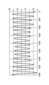
- FIG. 8 is an example of a waveform obtained based on the output of the strain gauge 100.
- the wiring 200 is passed through the notch 52x formed on the inner circumference of the stator core 52, and at least the notch 52x of the wiring 200 is passed through the notch 52x. It is a waveform when the passing part is shielded.
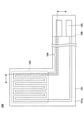
- FIG. 9 is a comparative example, and is a waveform when the wiring 200 is passed through the outside of the stator core 52 in the motor 1.
- the waveform obtained based on the output of the strain gauge 100 has a peak strain amount (output intensity) when the rolling element 33 passes directly under the resistor 103 of the strain gauge 100, and is an intermediate point of the adjacent rolling elements 33. Becomes the bottom and becomes a periodic waveform that repeats the peak and bottom. In FIG. 8, it can be confirmed that a periodic strain waveform that repeats peaks and bottoms is obtained without being buried in electromagnetic noise. On the other hand, in FIG. 9, the electromagnetic noise is large and the correct distortion waveform is not obtained.
- FIG. 10 is a plan view illustrating the strain gauge according to the first embodiment.
- FIG. 11 is a cross-sectional view illustrating the strain gauge according to the first embodiment, and shows a cross-sectional view taken along the line AA of FIG.
- the strain gauge 100 has a base material 101, a functional layer 102, a resistor 103, a wiring 104, and a terminal portion 105.
- the functional layer 102 may be provided as needed.
- the side of the base material 101 where the resistor 103 is provided is the upper side or one side, and the side where the resistor 103 is not provided is the lower side or the other side.
- the surface on the side where the resistor 103 is provided at each portion is defined as one surface or the upper surface, and the surface on the side where the resistor 103 is not provided is defined as the other surface or the lower surface.
- the strain gauge 100 can be used in an upside-down state, or can be arranged at an arbitrary angle.
- the plan view refers to viewing the object from the normal direction of the upper surface 101a of the base material 101
- the planar shape refers to the shape of the object viewed from the normal direction of the upper surface 101a of the base material 101.
- the base material 101 is a member that serves as a base layer for forming the resistor 103 and the like, and has flexibility.
- the thickness of the base material 101 is not particularly limited and may be appropriately selected depending on the intended purpose, but may be, for example, about 5 ⁇ m to 500 ⁇ m. In particular, when the thickness of the base material 101 is 5 ⁇ m to 200 ⁇ m, the strain from the strain-causing surface (for example, the outer peripheral surface 40a of the bearing housing 40) bonded to the lower surface of the base material 101 via the adhesive layer 150 is strained. It is preferable from the viewpoint of transmissibility and dimensional stability to the environment, and more preferably 10 ⁇ m or more is further preferable from the viewpoint of insulating property.
- the base material 101 is, for example, PI (polyethylene) resin, epoxy resin, PEEK (polyetheretherketone) resin, PEN (polyethylenenaphthalate) resin, PET (polyethylene terephthalate) resin, PPS (polyphenylene sulfide) resin, polyolefin resin and the like. It can be formed from the insulating resin film of.
- the film is a member having a thickness of about 500 ⁇ m or less and having flexibility.
- the base material 101 may be formed of, for example, an insulating resin film containing a filler such as silica or alumina.
- Materials other than the resin of the base material 101 include, for example, SiO 2 , ZrO 2 (including YSZ), Si, Si 2 N 3 , Al 2 O 3 (including sapphire), ZnO, and perovskite ceramics (CaTIO 3 ,). Crystalline materials such as BaTIO 3 ) can be mentioned, and amorphous glass and the like can be mentioned in addition to the above. Further, as the material of the base material 101, a metal such as aluminum, an aluminum alloy (duralumin), or titanium may be used. In this case, for example, an insulating film is formed on the metal base material 101.
- the functional layer 102 is formed on the upper surface 101a of the base material 101 as a lower layer of the resistor 103. That is, the planar shape of the functional layer 102 is substantially the same as the planar shape of the resistor 103 shown in FIG.
- the functional layer refers to a layer having at least a function of promoting crystal growth of the resistor 103, which is an upper layer. It is preferable that the functional layer 102 further has a function of preventing oxidation of the resistor 103 due to oxygen and moisture contained in the base material 101 and a function of improving the adhesion between the base material 101 and the resistor 103. ..
- the functional layer 102 may further have other functions.
- the insulating resin film constituting the base material 101 contains oxygen and water, particularly when the resistor 103 contains Cr (chromium), Cr forms a self-oxidizing film, so that the functional layer 102 oxidizes the resistor 103. It is effective to have a function to prevent it.
- the material of the functional layer 102 is not particularly limited as long as it has a function of promoting crystal growth of the resistor 103, which is at least the upper layer, and can be appropriately selected depending on the intended purpose.
- Cr chromium
- Ti. Ti.
- V vanadium
- Nb Niobium
- Ta Ta
- Ti Ni
- Zr Zyryl
- Hf Hafnium
- Si Si
- C Carbon
- Zn Zinc
- Cu Copper
- Bi Bi
- Fe Iron
- Mo Mo
- W Tungsten
- Ru Litenium
- Examples of the above alloy include FeCr, TiAl, FeNi, NiCr, CrCu and the like.
- Examples of the above -mentioned compound include TiN, TaN, Si 3N 4, TiO 2, Ta 2 O 5, SiO 2 , and the like .
- the film thickness of the functional layer 102 is preferably 1/20 or less of the film thickness of the resistor. Within such a range, the crystal growth of ⁇ -Cr can be promoted, and a part of the current flowing through the resistor can be prevented from flowing to the functional layer 102 to reduce the strain detection sensitivity.
- the film thickness of the functional layer 102 is more preferably 1/50 or less of the film thickness of the resistor. Within such a range, the crystal growth of ⁇ -Cr can be promoted, and a part of the current flowing through the resistor can be prevented from flowing to the functional layer 102 to further prevent the strain detection sensitivity from being lowered.
- the film thickness of the functional layer 102 is more preferably 1/100 or less of the film thickness of the resistor. Within such a range, it is possible to further prevent a part of the current flowing through the resistor from flowing to the functional layer 102 and reducing the strain detection sensitivity.
- the film thickness of the functional layer 102 is preferably 1 nm to 1 ⁇ m. Within such a range, the crystal growth of ⁇ -Cr can be promoted, and the functional layer 102 can be easily formed without cracks.
- the film thickness of the functional layer 102 is more preferably 1 nm to 0.8 ⁇ m. Within such a range, the crystal growth of ⁇ -Cr can be promoted, and the functional layer 102 can be more easily formed without cracks.
- the film thickness of the functional layer 102 is more preferably 1 nm to 0.5 ⁇ m. Within such a range, the crystal growth of ⁇ -Cr can be promoted, and the functional layer 102 can be more easily formed without cracks.
- the planar shape of the functional layer 102 is patterned substantially the same as the planar shape of the resistor shown in FIG. 10, for example.
- the planar shape of the functional layer 102 is not limited to the case where it is substantially the same as the planar shape of the resistor.
- the functional layer 102 may be formed in a solid shape at least in the region where the resistor is formed.
- the functional layer 102 may be formed in a solid shape on the entire upper surface of the base material 101.
- the thickness of the functional layer 102 is formed relatively thick so that the thickness of the functional layer 102 is 50 nm or more and 1 ⁇ m or less, and the functional layer 102 is formed in a solid shape. Since the surface area is increased, the heat generated when the resistor generates heat can be dissipated to the base material 101 side. As a result, in the strain gauge 100, it is possible to suppress a decrease in measurement accuracy due to self-heating of the resistor.
- the resistor 103 is a thin film formed on the upper surface of the functional layer 102 in a predetermined pattern, and is a sensitive portion that undergoes strain to cause a change in resistance.
- the resistor 103 can be formed from, for example, a material containing Cr (chromium), a material containing Ni (nickel), or a material containing both Cr and Ni. That is, the resistor 103 can be formed from a material containing at least one of Cr and Ni. Examples of the material containing Cr include a Cr mixed phase film. Examples of the material containing Ni include Cu—Ni (copper nickel). Examples of the material containing both Cr and Ni include Ni—Cr (nickel chromium).
- the Cr mixed phase film is a film in which Cr, CrN, Cr 2N and the like are mixed.
- the Cr mixed phase film may contain unavoidable impurities such as chromium oxide. Further, a part of the material constituting the functional layer 102 may be diffused in the Cr mixed phase film. In this case, the material constituting the functional layer 102 and nitrogen may form a compound.
- the Cr mixed phase film may contain Ti or TiN (titanium nitride).
- the thickness of the resistor 103 is not particularly limited and can be appropriately selected depending on the purpose, but can be, for example, about 0.05 ⁇ m to 2 ⁇ m.
- the thickness of the resistor 103 is 0.1 ⁇ m or more, the crystallinity of the crystals constituting the resistor 103 (for example, the crystallinity of ⁇ -Cr) is improved, and when the thickness is 1 ⁇ m or less, the resistor is preferable. It is more preferable in that it can reduce cracks in the film and warpage from the base material 101 due to the internal stress of the film constituting 103.
- the resistor 103 By forming the resistor 103 on the functional layer 102, the resistor 103 can be formed with a stable crystal phase, so that the stability of the gauge characteristics (gauge ratio, gauge coefficient temperature coefficient TCS, and resistance temperature coefficient TCR) is improved. can.
- the resistor 103 when the resistor 103 is a Cr mixed phase film, the resistor 103 containing ⁇ -Cr (alpha chromium) as a main component can be formed by providing the functional layer 102. Since ⁇ -Cr is a stable crystal phase, the stability of gauge characteristics can be improved.
- ⁇ -Cr alpha chromium
- the main component means that the target substance occupies 50% by mass or more of all the substances constituting the resistor.
- the resistor 103 is a Cr mixed film
- the resistor 103 preferably contains 80% by weight or more of ⁇ -Cr, and more preferably 90% by weight or more, from the viewpoint of improving the gauge characteristics.
- ⁇ -Cr is Cr of a bcc structure (body-centered cubic lattice structure).
- the Cr N and Cr 2 N contained in the Cr mixed film are preferably 20% by weight or less.
- Cr N and Cr 2 N contained in the Cr mixed phase film are 20% by weight or less, a decrease in the gauge ratio can be suppressed.
- the ratio of Cr 2N in Cr N and Cr 2N is preferably 80% by weight or more and less than 90% by weight, and more preferably 90% by weight or more and less than 95% by weight.
- the ratio of Cr 2 N in Cr N and Cr 2 N is 90% by weight or more and less than 95% by weight, the decrease in TCR (negative TCR) becomes more remarkable due to Cr 2 N having semiconducting properties. .. Further, by reducing the use of ceramics, brittle fracture is reduced.
- the gauge characteristics can be improved by diffusing the metal (for example, Ti) constituting the functional layer 102 into the Cr mixed phase film.
- the gauge ratio of the strain gauge 100 can be 10 or more, and the gauge ratio temperature coefficient TCS and the resistance temperature coefficient TCR can be in the range of ⁇ 1000 ppm / ° C. to + 1000 ppm / ° C.
- the terminal portion 105 extends from both ends of the resistor 103 via the wiring 104, and is wider than the resistor 103 and the wiring 104 in a plan view and is formed in a substantially rectangular shape.
- the terminal portion 105 is a pair of electrodes for outputting a change in the resistance value of the resistor 103 caused by strain to the outside.
- the resistor 103 extends from one of the terminal portion 105 and the wiring 104 while being folded back in a zigzag manner, and is connected to the other wiring 104 and the terminal portion 105, for example.
- the upper surface of the terminal portion 105 may be coated with a metal having better solderability than the terminal portion 105.
- the resistor 103, the wiring 104, and the terminal portion 105 are designated by different codes for convenience, they can be integrally formed of the same material in the same process.
- a cover layer 106 (insulating resin layer) may be provided on the upper surface 101a of the base material 101 so as to cover the resistor 103 and the wiring 104 and expose the terminal portion 105.
- the cover layer 106 may be provided so as to cover the entire portion excluding the terminal portion 105.
- the cover layer 106 can be formed of, for example, an insulating resin such as PI resin, epoxy resin, PEEK resin, PEN resin, PET resin, PPS resin, and composite resin (for example, silicone resin and polyolefin resin).
- the cover layer may contain a filler or a pigment.
- the thickness of the cover layer is not particularly limited and may be appropriately selected depending on the intended purpose, but may be, for example, about 2 ⁇ m to 30 ⁇ m.
- the base material 101 is prepared, and the functional layer 102 is formed on the upper surface 101a of the base material 101.
- the materials and thicknesses of the base material 101 and the functional layer 102 are as described above. However, the functional layer 102 may be provided as needed.
- the functional layer 102 can be formed into a vacuum by, for example, a conventional sputtering method in which Ar (argon) gas is introduced into a chamber, targeting a raw material capable of forming the functional layer 102.
- Ar argon
- the functional layer 102 is formed while etching the upper surface 101a of the base material 101 with Ar, so that the film forming amount of the functional layer 102 can be minimized and the adhesion improving effect can be obtained. can.
- the functional layer 102 may be formed by another method.
- the adhesion improving effect is obtained by activating the upper surface 101a of the base material 101 by plasma treatment using Ar or the like before the film formation of the functional layer 102, and then the functional layer 102 is evacuated by the magnetron sputtering method.
- a method of forming a film may be used.
- the functional layer 102 and the resistor 103, the wiring 104, and the terminal portion 105 are shown in FIG. 10 by photolithography. Patterning is performed in the plane shape shown in.
- the materials and thicknesses of the resistor 103, the wiring 104, and the terminal portion 105 are as described above.
- the resistor 103, the wiring 104, and the terminal portion 105 can be integrally formed of the same material.
- the resistor 103, the wiring 104, and the terminal portion 105 can be formed into a film by, for example, a magnetron sputtering method targeting a raw material capable of forming the resistor 103, the wiring 104, and the terminal portion 105.
- the resistor 103, the wiring 104, and the terminal portion 105 may be formed into a film by a reactive sputtering method, a vapor deposition method, an arc ion plating method, a pulse laser deposition method, or the like, instead of the magnetron sputtering method.
- the combination of the material of the functional layer 102 and the material of the resistor 103, the wiring 104, and the terminal portion 105 is not particularly limited and may be appropriately selected depending on the intended purpose.
- Ti is used as the functional layer 102 and the resistor is used.
- a Cr mixed-phase film containing ⁇ -Cr (alpha chromium) as a main component can be formed as the 103, the wiring 104, and the terminal portion 105.
- the resistor 103, the wiring 104, and the terminal portion 105 can be formed into a film by a magnetron sputtering method in which Ar gas is introduced into the chamber, targeting a raw material capable of forming a Cr mixed-phase film.
- Ar gas is introduced into the chamber, targeting a raw material capable of forming a Cr mixed-phase film.
- pure Cr may be targeted, an appropriate amount of nitrogen gas may be introduced into the chamber together with Ar gas, and the resistor 103, the wiring 104, and the terminal portion 105 may be formed into a film by the reactive sputtering method.
- the growth surface of the Cr mixed-phase film is defined by the functional layer 102 made of Ti, and a Cr mixed-phase film containing ⁇ -Cr as a main component, which has a stable crystal structure, can be formed.
- the gauge characteristics are improved by diffusing Ti constituting the functional layer 102 in the Cr mixed phase film.
- the gauge ratio of the strain gauge 100 can be 10 or more, and the gauge ratio temperature coefficient TCS and the resistance temperature coefficient TCR can be in the range of ⁇ 1000 ppm / ° C. to + 1000 ppm / ° C.
- the functional layer 102 made of Ti has a function of promoting crystal growth of the resistor 103 and prevents oxidation of the resistor 103 by oxygen or moisture contained in the substrate 101. It has all the functions and the function of improving the adhesion between the base material 101 and the resistor 103. The same applies when Ta, Si, Al, or Fe is used as the functional layer 102 instead of Ti.
- the strain gauge 100 is completed by providing a cover layer 106 that covers the resistor 103 and the wiring 104 and exposes the terminal portion 105 on the upper surface 101a of the base material 101.
- the cover layer 106 is, for example, laminated with a semi-curable thermosetting insulating resin film on the upper surface 101a of the base material 101 so as to cover the resistor 103 and the wiring 104 and expose the terminal portion 105, and heat the cover layer 106. Can be produced by curing.
- the cover layer 106 is coated with a resistor 103 and a wiring 104 on the upper surface 101a of the base material 101, and a liquid or paste-like thermosetting insulating resin is applied so as to expose the terminal portion 105, and the cover layer 106 is heated and cured. May be produced.
- the functional layer 102 under the resistor 103 By providing the functional layer 102 under the resistor 103 in this way, the crystal growth of the resistor 103 can be promoted, and the resistor 103 having a stable crystal phase can be produced. As a result, the stability of the gauge characteristics can be improved in the strain gauge 100. Further, the material constituting the functional layer 102 diffuses into the resistor 103, so that the gauge characteristics of the strain gauge 100 can be improved.
- the strain gauge 100 using a Cr mixed phase film as the material of the resistor 103 has achieved high sensitivity (500% or more compared to the conventional method) and miniaturization (1/10 or less compared to the conventional method). For example, while the output of the conventional strain gauge is about 0.04 mV / 2V, the strain gauge 100 can obtain an output of 0.3 mV / 2 V or more. Further, the size of the strain gauge 100 (gauge length x gauge width) is 0.3 mm x 0.3 mm, whereas the size of the conventional strain gauge (gauge length x gauge width) is about 3 mm x 3 mm. It can be downsized to some extent.
- the strain gauge 100 using the Cr mixed film as the material of the resistor 103 is small and can be easily attached to the recess 40x provided on the outer peripheral surface 40a of the bearing housing 40. Therefore, it is particularly suitable for use in a motor 1 using a small rolling bearing 30 having a diameter (outer diameter of the outer ring 31) of 30 mm or less. Further, since the strain gauge 100 using the Cr mixed phase film as the material of the resistor 103 has high sensitivity and can detect a small displacement, it is possible to detect a minute strain which was difficult to detect in the past. That is, by having the strain gauge 100 using the Cr mixed phase film as the material of the resistor 103, it is possible to realize the motor 1 having a function of accurately detecting the strain.
- FIG. 12 is a partially enlarged cross-sectional view of the vicinity of the rotor shaft of the motor according to the second embodiment.
- FIG. 13 is a partially enlarged plan view of a portion D in FIG. In FIG. 13, the rolling bearing is shown in a simplified manner, and some members are not shown.
- the strain gauge 100 is fixed on the inner side in the radial direction (on the rotation axis m side) of the inner diameter of the stator core 52. Specifically, the strain gauge 100 is fixed to the outer peripheral surface 31a of the outer ring 31 via an adhesive layer.
- the inner peripheral surface 40b of the bearing housing 40 facing the strain gauge 100 in the radial direction is provided with a recess 40y for preventing interference with the strain gauge 100. That is, the strain gauge 100 is fixed to the outer peripheral surface 31a of the outer ring 31 facing the recess 40y provided on the inner peripheral surface 40b of the bearing housing 40.
- the recess 40y may be provided in a part of the inner peripheral surface 40b of the bearing housing 40 in the circumferential direction, or may be provided over the entire circumference of the inner peripheral surface 40b of the bearing housing 40.
- the inner peripheral surface 40b of the bearing housing 40 and the strain gauge 100 do not interfere with each other when the rolling bearing 30 is attached to the inner peripheral surface 40b of the bearing housing 40. .. Further, the inner peripheral surface 40b of the bearing housing 40 axially below the recess y is fitted in a gap with the rolling bearing 30.
- the wiring 200 goes around the upper end in the axial direction of the bearing housing 40, enters the notch 52x formed on the inner circumference of the stator core 52, passes through the notch 52x, and is axially lower than the stator core 52, that is, on the outer side of the motor 1. It has been pulled out.
- the wiring 200 electrically connected to the strain gauge 100 is pulled out axially downward from the stator core 52 through a notch 52x provided on the inner circumference of the stator core 52, and is outside the motor 1. It is pulled out directly to.
- the wiring 200 is not limited to this, and the wiring 200 electrically connected to the strain gauge 100 is pulled out axially lower than the stator core 52 through the notch 52x provided on the inner circumference of the stator core 52, and the motor. It may be electrically connected to the circuit board arranged inside 1. In this case, another wiring is drawn from the circuit board to the outside of the motor 1.
- the wiring 200 is shielded from at least a portion passing through the notch 52x because it is interfered with by electromagnetic noise generated from the coil 53 and the like.
- the wiring 200 may be, for example, a coaxial cable, or may have a structure in which a solid GND is formed on at least one side of the flexible substrate. From the viewpoint of suppressing the influence of electromagnetic noise, it is preferable that the outer ring 31 has a GND having the same potential as the shield portion of the wiring 200.
- the strain gauge 100 may be fixed to the outer peripheral surface 31a of the outer ring 31.
- the outer peripheral surface 31a of the outer ring 31 is at a position where strain can be easily detected, even a slight strain can be detected. That is, when the outer ring 31 of the rolling bearing 30 is slightly distorted, this slight strain can be detected by the strain gauge 100 fixed to the outer peripheral surface 31a of the outer ring 31.
- the inner peripheral surface of the bearing housing 40 is provided with the recess 40y on the inner peripheral surface 40b of the bearing housing 40 that faces the strain gauge 100 in the radial direction. Interference between 40b and the strain gauge 100 can be prevented.
- the influence of electromagnetic noise is affected as in the first embodiment. It can be significantly suppressed.
- the axial fan motor is exemplified as the motor, but the present invention is not limited to this, and the present invention can be widely applied to motors other than the axial fan motor.
- strain gauges are provided on the rolling bearings arranged on the upper side or the rolling bearings arranged on the lower side in FIG. 1 and the like is shown, but strain gauges are provided on both rolling bearings. May be good. Further, a plurality of strain gauges may be provided on one or both of the rolling bearing arranged on the upper side and the rolling bearing arranged on the lower side in FIG. 1 and the like.
Abstract
This motor has: a roller bearing that supports a rotor shaft in a rotatable state; a bearing housing that holds the roller bearing; a stator core fixed to the outer circumference of the bearing housing; and a strain gauge which is equipped with a resistor for detecting the strain of the roller bearing. The strain gauge is fixed radially inside with respect to the inner diameter of the stator core.
Description
本発明は、モータに関する。
The present invention relates to a motor.
転がり軸受を備えたモータにおいて、モータ回転時は、転がり軸受内の球体が自転し、転がり軸受に僅かにひずみを与える。転がり軸受のひずみは、転がり軸受内部の状態によって変化する。例えば、転がり軸受内部に摩耗粉が発生して球体や転動面に付着した場合は、付着物が外輪を押し上げ、外輪の振幅が大きくなる。又、球体や転動面の摩耗が進んだ場合は、球体と転動面間の面圧が下がり、外輪の振幅が小さくなる。
In a motor equipped with a rolling bearing, when the motor rotates, the sphere in the rolling bearing rotates and gives a slight strain to the rolling bearing. The strain of a rolling bearing changes depending on the state inside the rolling bearing. For example, when wear debris is generated inside a rolling bearing and adheres to a sphere or a rolling surface, the adhered material pushes up the outer ring and the amplitude of the outer ring increases. Further, when the wear of the sphere and the rolling surface progresses, the surface pressure between the sphere and the rolling surface decreases, and the amplitude of the outer ring becomes small.
このような転がり軸受内部の状態の変化は、できるだけ早く検出することが好ましい。そのため、例えば、振動センサが固定された構造のモータが開示されている(例えば、特許文献1参照)。
It is preferable to detect such a change in the state inside the rolling bearing as soon as possible. Therefore, for example, a motor having a structure in which a vibration sensor is fixed is disclosed (see, for example, Patent Document 1).
しかしながら、転がり軸受に生じるひずみは僅かであるから、センサをどこに配置するかは重要である。例えば、センサとしてひずみゲージを用いる場合、転がり軸受に生じる僅かなひずみを十分に検知できる位置にひずみゲージを配置する必要があるが、ひずみゲージを配置するスペースをモータ内に確保することは容易ではなかった。
However, since the strain generated in the rolling bearing is small, it is important where to place the sensor. For example, when a strain gauge is used as a sensor, it is necessary to arrange the strain gauge at a position where it can sufficiently detect the slight strain generated in the rolling bearing, but it is not easy to secure a space for arranging the strain gauge in the motor. There wasn't.
本発明は、上記の点に鑑みてなされたもので、ひずみを検知しやすい位置にひずみゲージを配置したモータを提供することを目的とする。
The present invention has been made in view of the above points, and an object of the present invention is to provide a motor in which a strain gauge is arranged at a position where strain can be easily detected.
本モータは、ロータシャフトを回転可能な状態で支持する転がり軸受と、前記転がり軸受を保持する軸受ハウジングと、前記軸受ハウジングの外周に固定されたステータコアと、前記転がり軸受のひずみを検出する抵抗体を備えたひずみゲージと、を有し、前記ひずみゲージは、前記ステータコアの内径よりも径方向内側に固定されている。
This motor includes a rolling bearing that supports the rotor shaft in a rotatable state, a bearing housing that holds the rolling bearing, a stator core fixed to the outer periphery of the bearing housing, and a resistor that detects strain in the rolling bearing. The strain gauge is fixed to the inside in the radial direction with respect to the inner diameter of the stator core.
開示の技術によれば、ひずみを検知しやすい位置にひずみゲージを配置したモータを提供できる。
According to the disclosed technology, it is possible to provide a motor in which a strain gauge is placed at a position where strain can be easily detected.
以下、図面を参照して発明を実施するための形態について説明する。各図面において、同一構成部分には同一符号を付し、重複した説明を省略する場合がある。
Hereinafter, a mode for carrying out the invention will be described with reference to the drawings. In each drawing, the same components may be designated by the same reference numerals and duplicate explanations may be omitted.
〈第1実施形態〉
(モータの全体構造)
図1は、第1実施形態に係るモータを例示する断面図である。図1に示すように、モータ1は、インペラ10と、ロータシャフト20と、転がり軸受30と、軸受ハウジング40と、ステータ50と、ロータ60と、ケーシング70とを有する軸流ファンモータである。 <First Embodiment>
(Overall structure of motor)
FIG. 1 is a cross-sectional view illustrating the motor according to the first embodiment. As shown in FIG. 1, themotor 1 is an axial flow fan motor having an impeller 10, a rotor shaft 20, a rolling bearing 30, a bearing housing 40, a stator 50, a rotor 60, and a casing 70.
(モータの全体構造)
図1は、第1実施形態に係るモータを例示する断面図である。図1に示すように、モータ1は、インペラ10と、ロータシャフト20と、転がり軸受30と、軸受ハウジング40と、ステータ50と、ロータ60と、ケーシング70とを有する軸流ファンモータである。 <First Embodiment>
(Overall structure of motor)
FIG. 1 is a cross-sectional view illustrating the motor according to the first embodiment. As shown in FIG. 1, the
インペラ10は、ロータハウジング11と、ロータハウジング11の外周に設けられた羽根12とを有している。インペラ10の中心には、回転軸mを有するロータシャフト20が固定されている。ロータシャフト20は、長手方向の両端近傍に配置された2つの転がり軸受30により回転可能な状態で支持されている。
The impeller 10 has a rotor housing 11 and blades 12 provided on the outer periphery of the rotor housing 11. A rotor shaft 20 having a rotation axis m is fixed to the center of the impeller 10. The rotor shaft 20 is rotatably supported by two rolling bearings 30 arranged near both ends in the longitudinal direction.
転がり軸受30は、外輪31と、内輪32と、複数の転動体33とを有している。外輪31は、回転軸mを中心軸とする円筒形の構造体である。内輪32は、外輪31の内周側に外輪31と同軸状に配置された円筒形の構造体である。複数の転動体33の各々は外輪31と内輪32との間に形成される軌道内に配置された球体である。軌道内にはグリース等の潤滑剤が封入される。
The rolling bearing 30 has an outer ring 31, an inner ring 32, and a plurality of rolling elements 33. The outer ring 31 is a cylindrical structure having a rotation axis m as a central axis. The inner ring 32 is a cylindrical structure arranged coaxially with the outer ring 31 on the inner peripheral side of the outer ring 31. Each of the plurality of rolling elements 33 is a sphere arranged in an orbit formed between the outer ring 31 and the inner ring 32. A lubricant such as grease is sealed in the track.
転がり軸受30は、軸受ハウジング40に圧入や接着等により固定され、軸受ハウジング40に保持されている。軸受ハウジング40は、外輪31の外周面を全周に亘って押さえている。軸受ハウジング40は、例えば、真鍮等の金属により形成できる。
The rolling bearing 30 is fixed to the bearing housing 40 by press fitting, adhesion, or the like, and is held in the bearing housing 40. The bearing housing 40 presses the outer peripheral surface of the outer ring 31 over the entire circumference. The bearing housing 40 can be formed of, for example, a metal such as brass.
ステータ50は、インシュレータ51と、ステータコア52と、コイル53とを有し、軸受ハウジング40の外周に配置されている。ステータコア52は、例えば、軸受ハウジング40の外周に圧入等により固定されている。
The stator 50 has an insulator 51, a stator core 52, and a coil 53, and is arranged on the outer periphery of the bearing housing 40. The stator core 52 is fixed to the outer periphery of the bearing housing 40 by press fitting or the like, for example.
ロータ60は、ロータハウジング11の内側に一体的に設けられたロータヨーク61と、ロータヨーク61の内側に装着されたロータマグネット62とを有している。なお、図1の例では、ロータヨーク61は、ロータハウジング11の内側に一体的に設けられているが、これには限定されず、ロータヨーク61はロータハウジング11の内側に装着されてもよい。又、ロータシャフト20は、ロータヨーク61に装着されてロータハウジング11の中心に固定されているが、ロータシャフト20はロータハウジング11に直接固定してもよい。
The rotor 60 has a rotor yoke 61 integrally provided inside the rotor housing 11, and a rotor magnet 62 mounted inside the rotor yoke 61. In the example of FIG. 1, the rotor yoke 61 is integrally provided inside the rotor housing 11, but the present invention is not limited to this, and the rotor yoke 61 may be mounted inside the rotor housing 11. Further, although the rotor shaft 20 is mounted on the rotor yoke 61 and fixed to the center of the rotor housing 11, the rotor shaft 20 may be directly fixed to the rotor housing 11.
ケーシング70は、インペラ10の外周を覆うケーシング外枠71と、軸受ハウジング40を固定するベース部ハブ72と、ケーシング外枠71とベース部ハブ72とを連結する静翼73とを有している。
The casing 70 has a casing outer frame 71 that covers the outer periphery of the impeller 10, a base hub 72 that fixes the bearing housing 40, and a stationary blade 73 that connects the casing outer frame 71 and the base hub 72. ..
なお、図1の例では、ケーシング外枠71とベース部ハブ72とが、静翼73で連結されている場合を示しているが、ケーシング外枠71とベース部ハブ72とは、連結シャフトのような棒状の構造で連結されてもよい。
In the example of FIG. 1, the case where the casing outer frame 71 and the base portion hub 72 are connected by the stationary blade 73 is shown, but the casing outer frame 71 and the base portion hub 72 are connected to each other by the connecting shaft. It may be connected by such a rod-shaped structure.
又、軸受ハウジング40は、ケーシング70を樹脂で射出成形するときに、ベース部ハブ72に一体化するように固定してもよいが、先にケーシング70を成形しておき、後からベース部ハブ72の部分に固定するようにしてもよい。
Further, the bearing housing 40 may be fixed so as to be integrated with the base portion hub 72 when the casing 70 is injection-molded with resin, but the casing 70 may be molded first and then the base portion hub. It may be fixed to the portion 72.
モータ1において、ステータ50とロータ60とでモータ部80が構成されており、電源部(図示せず)からコイル53に電流を供給することにより、軸受ハウジング40内に回転自在に支持されたロータシャフト20の中心軸を回転軸mとしてインペラ10が回転する。すなわち、モータ1は、所謂アウターロータ型のモータである。
In the motor 1, the motor unit 80 is composed of the stator 50 and the rotor 60, and the rotor is rotatably supported in the bearing housing 40 by supplying a current from the power supply unit (not shown) to the coil 53. The impeller 10 rotates with the central axis of the shaft 20 as the rotation axis m. That is, the motor 1 is a so-called outer rotor type motor.
モータ1において、図1の上側が吸込み口側であり、下側が吹出し口側である。従って、モータ1では、ケーシング外枠71の空気の吸込み口側にインペラ10が設けられ、吹出し口側にベース部ハブ72が設けられている。
In the motor 1, the upper side in FIG. 1 is the suction port side, and the lower side is the outlet side. Therefore, in the motor 1, the impeller 10 is provided on the air suction port side of the casing outer frame 71, and the base portion hub 72 is provided on the blowout port side.
図2は、第1実施形態に係るモータのロータシャフト近傍の部分拡大断面図である。図3は、図2のC部の部分拡大平面図である。図4は、軸受ハウジング外周部の部分拡大斜視図である。なお、図3では、転がり軸受は簡略化して図示されており、又、一部の部材の図示は省略されている。
FIG. 2 is a partially enlarged cross-sectional view of the vicinity of the rotor shaft of the motor according to the first embodiment. FIG. 3 is a partially enlarged plan view of a portion C in FIG. FIG. 4 is a partially enlarged perspective view of the outer peripheral portion of the bearing housing. In FIG. 3, the rolling bearing is shown in a simplified manner, and some members are not shown.
図2~図4に示すように、ひずみゲージ100は、ステータコア52の内径よりも径方向内側(回転軸m側)に固定されている。具体的には、転がり軸受30を保持する軸受ハウジング40の外周面40aに、回転軸m側に窪む凹部40xが設けられている。そして、凹部40xに、ひずみゲージ100が接着剤等により固定されている。なお、ステータコア52の内径とは、ステータコア52において軸受ハウジング40の外周面40aに接している部分である。
As shown in FIGS. 2 to 4, the strain gauge 100 is fixed on the inner side in the radial direction (on the rotation axis m side) of the inner diameter of the stator core 52. Specifically, the outer peripheral surface 40a of the bearing housing 40 that holds the rolling bearing 30 is provided with a recess 40x that is recessed on the rotation axis m side. Then, the strain gauge 100 is fixed to the recess 40x with an adhesive or the like. The inner diameter of the stator core 52 is a portion of the stator core 52 that is in contact with the outer peripheral surface 40a of the bearing housing 40.
図2~図4に示す例では、凹部40xは、軸受ハウジング40の外周面40aの周方向の一部に設けられている。ただし、凹部40xは、図2~図4に示す形態には限定されない。例えば、図5に示すように、凹部40xは、軸受ハウジング40の外周面40aの軸方向端部に達してもよい。また、図6に示すように、凹部40xは、軸受ハウジング40の外周面40aの全周にわたって設けられてもよい。
In the example shown in FIGS. 2 to 4, the recess 40x is provided in a part of the peripheral surface 40a of the bearing housing 40 in the circumferential direction. However, the recess 40x is not limited to the form shown in FIGS. 2 to 4. For example, as shown in FIG. 5, the recess 40x may reach the axial end of the outer peripheral surface 40a of the bearing housing 40. Further, as shown in FIG. 6, the recess 40x may be provided over the entire circumference of the outer peripheral surface 40a of the bearing housing 40.
又、下側に配置された転がり軸受30を保持する部分の軸受ハウジング40の外周面40aに、回転軸m側に窪む凹部40xを設けてもよい。例えば、図7に示すように、凹部40xは、軸受ハウジング40の外周面40aの全周にわたって設けることができる。或いは、凹部40xは、軸受ハウジング40の外周面40aの周方向の一部に設けられてもよい。
Further, a recess 40x recessed on the rotation axis m side may be provided on the outer peripheral surface 40a of the bearing housing 40 of the portion holding the rolling bearing 30 arranged on the lower side. For example, as shown in FIG. 7, the recess 40x can be provided over the entire circumference of the outer peripheral surface 40a of the bearing housing 40. Alternatively, the recess 40x may be provided in a part of the outer peripheral surface 40a of the bearing housing 40 in the circumferential direction.
ひずみゲージ100は、転がり軸受30のひずみ(例えば、外輪31のひずみ)を検出する抵抗体103を備えたセンサである。軸受ハウジング40の外周面40aに設けられた凹部40xにひずみゲージ100を配置することにより、転がり軸受30のひずみは、軸受ハウジング40を介してひずみゲージ100に伝わり、ひずみゲージ100で検出可能である。本実施形態では、ひずみゲージ100は、転がり軸受30のひずみを抵抗体103の抵抗値の変化として検出する。
The strain gauge 100 is a sensor provided with a resistor 103 for detecting the strain of the rolling bearing 30 (for example, the strain of the outer ring 31). By arranging the strain gauge 100 in the recess 40x provided on the outer peripheral surface 40a of the bearing housing 40, the strain of the rolling bearing 30 is transmitted to the strain gauge 100 via the bearing housing 40 and can be detected by the strain gauge 100. .. In the present embodiment, the strain gauge 100 detects the strain of the rolling bearing 30 as a change in the resistance value of the resistor 103.
なお、ひずみゲージ100において、抵抗体103は、長手方向(ゲージ長方向)を軸受ハウジング40の周方向に向けて配置されている。軸受ハウジング40の周方向は軸方向よりも伸縮し易いため、抵抗体103の長手方向を軸受ハウジング40の周方向に向けて配置することで、大きなひずみ波形を得ることができる。
In the strain gauge 100, the resistor 103 is arranged with the longitudinal direction (gauge length direction) facing the circumferential direction of the bearing housing 40. Since the circumferential direction of the bearing housing 40 is easier to expand and contract than the axial direction, a large strain waveform can be obtained by arranging the longitudinal direction of the resistor 103 toward the circumferential direction of the bearing housing 40.
ひずみゲージ100は、配線104を介して抵抗体103の両端に接続された一対の端子部105を有しており、各々の端子部105には、はんだ等により、配線200が電気的に接続されている。配線200は、ステータコア52の内周に設けられたノッチ52x(配線を通すための凹部)を通って、ステータコア52よりも軸方向下側、つまりモータ1の外部側に引き出されている。ノッチ52xは、例えば、回転軸mと略平行に設けられた細長状の凹部とすることができる。
The strain gauge 100 has a pair of terminal portions 105 connected to both ends of the resistor 103 via the wiring 104, and the wiring 200 is electrically connected to each terminal portion 105 by solder or the like. ing. The wiring 200 is drawn out from the stator core 52 to the lower side in the axial direction, that is, to the outer side of the motor 1 through a notch 52x (recess for passing the wiring) provided on the inner circumference of the stator core 52. The notch 52x can be, for example, an elongated recess provided substantially parallel to the axis of rotation m.
なお、図2では、ひずみゲージ100と電気的に接続された配線200は、ステータコア52の内周に設けられたノッチ52xを通ってステータコア52よりも軸方向下側に引き出され、モータ1の外部に直接引き出されている。しかし、これには限定されず、ひずみゲージ100と電気的に接続された配線200は、ステータコア52の内周に設けられたノッチ52xを通ってステータコア52よりも軸方向下側に引き出され、モータ1の内部に配置された回路基板と電気的に接続されてもよい。この場合には、回路基板から別の配線がモータ1の外部に引き出される。
In FIG. 2, the wiring 200 electrically connected to the strain gauge 100 is pulled out axially downward from the stator core 52 through a notch 52x provided on the inner circumference of the stator core 52, and is outside the motor 1. It is pulled out directly to. However, the wiring 200 is not limited to this, and the wiring 200 electrically connected to the strain gauge 100 is pulled out axially lower than the stator core 52 through the notch 52x provided on the inner circumference of the stator core 52, and the motor. It may be electrically connected to the circuit board arranged inside 1. In this case, another wiring is drawn from the circuit board to the outside of the motor 1.
配線200は、コイル53等から発生する電磁ノイズの干渉を受けるため、少なくとも一部分がシールドされていることが好ましい。図2~図6に示す例では、配線200は、少なくともノッチ52xを通る部分がシールドされていることが好ましい。図7に示す例では、配線200は、少なくともモータ1の内部を通過する部分がシールドされていることが好ましい。
Since the wiring 200 is interfered with by electromagnetic noise generated from the coil 53 and the like, it is preferable that at least a part of the wiring 200 is shielded. In the example shown in FIGS. 2 to 6, it is preferable that at least a portion of the wiring 200 passing through the notch 52x is shielded. In the example shown in FIG. 7, it is preferable that at least a portion of the wiring 200 passing through the inside of the motor 1 is shielded.
配線200は、例えば、同軸ケーブルであってもよいし、フレキシブル基板の少なくとも一方側にベタ状のGNDが形成された構造等であってもよい。電磁ノイズの影響を抑制する観点から、ひずみゲージ100が固定されている軸受ハウジング40は、配線200のシールド部分と同電位のGNDであることが好ましい。例えば導電性接着剤により軸受ハウジング40と配線200のシールド部分とを接着することで、両者を同電位のGNDとすることができる。導電性接着剤としては、例えば銀、ニッケル、金、銅、カーボンブラック等の粒子が接着剤中に分散したペーストが挙げられる。
The wiring 200 may be, for example, a coaxial cable, or may have a structure in which a solid GND is formed on at least one side of the flexible substrate. From the viewpoint of suppressing the influence of electromagnetic noise, the bearing housing 40 to which the strain gauge 100 is fixed is preferably GND having the same potential as the shield portion of the wiring 200. For example, by adhering the bearing housing 40 and the shield portion of the wiring 200 with a conductive adhesive, both can be grounded at the same potential. Examples of the conductive adhesive include a paste in which particles such as silver, nickel, gold, copper, and carbon black are dispersed in the adhesive.
なお、図7の場合には、ひずみゲージ100と電気的に接続された配線200は、例えば、凹部40xからモータ1の外部に直接引き出されるか、或いはモータ1の内部に配置された回路基板と電気的に接続される。そのため、図7の場合には、ステータコア52の内周に、ノッチ52xを設けなくてもよい。
In the case of FIG. 7, the wiring 200 electrically connected to the strain gauge 100 is, for example, directly drawn out from the recess 40x to the outside of the motor 1, or is a circuit board arranged inside the motor 1. It is electrically connected. Therefore, in the case of FIG. 7, it is not necessary to provide the notch 52x on the inner circumference of the stator core 52.
このように、モータ1では、ひずみを検知しやすい位置であるステータコア52の内径よりも径方向内側にひずみゲージ100を配置しているため、僅かなひずみも検知できる。すなわち、転がり軸受30の外輪31が僅かでもひずんだ場合、軸受ハウジング40も同様にひずむため、この僅かなひずみを軸受ハウジング40の外周面40aに設けられた凹部40xに固定されたひずみゲージ100で検知できる。
As described above, in the motor 1, since the strain gauge 100 is arranged radially inside the inner diameter of the stator core 52, which is a position where strain can be easily detected, even a slight strain can be detected. That is, if the outer ring 31 of the rolling bearing 30 is slightly distorted, the bearing housing 40 is also distorted. Therefore, this slight strain is applied by the strain gauge 100 fixed to the recess 40x provided on the outer peripheral surface 40a of the bearing housing 40. Can be detected.
ひずみゲージ100の端子部105間で得られたひずみ波形を、例えばFFT解析(高速フーリエ変換)することで、転がり軸受け30の状態を監視できる。よって、ひずみ波形の変化をモニタリングすることで、転がり軸受け30の異常を検知し、モータ1が回転不具合を発生する前に異常を検知することが可能となる。例えば、サーバの冷却等に用いられる軸流ファンモータは、常に動作しており、一時的にでもストップすると冷却能力が下がる。この場合、軸流ファンモータの異常を少しでも早く検知したいため、転がり軸受け30の状態をモニタリングすることは特に有効である。
The state of the rolling bearing 30 can be monitored by, for example, FFT analysis (fast Fourier transform) of the strain waveform obtained between the terminal portions 105 of the strain gauge 100. Therefore, by monitoring the change in the strain waveform, it is possible to detect the abnormality of the rolling bearing 30 and detect the abnormality before the motor 1 causes a rotation failure. For example, an axial fan motor used for cooling a server is always in operation, and if it is stopped even temporarily, the cooling capacity is lowered. In this case, it is particularly effective to monitor the state of the rolling bearing 30 because it is desired to detect the abnormality of the axial fan motor as soon as possible.
又、モータ1では、軸受ハウジング40の外周面40aに設けられた凹部40xにひずみゲージ100が固定されており、ひずみゲージ100は外周面40aより外側にはみ出ることがない。そのため、軸受ハウジング40にひずみゲージ100を固定した後に、軸受ハウジング40の外周にステータコア52を圧入することが可能である。この際、ステータコア52の内周面とひずみゲージ100とは干渉しない。なお、配線200は、ステータコア52の内周に形成されたノッチ52xに通すようにする。
Further, in the motor 1, the strain gauge 100 is fixed to the recess 40x provided on the outer peripheral surface 40a of the bearing housing 40, and the strain gauge 100 does not protrude outside the outer peripheral surface 40a. Therefore, after fixing the strain gauge 100 to the bearing housing 40, it is possible to press-fit the stator core 52 into the outer periphery of the bearing housing 40. At this time, the inner peripheral surface of the stator core 52 and the strain gauge 100 do not interfere with each other. The wiring 200 is passed through a notch 52x formed on the inner circumference of the stator core 52.
又、モータ1では、例えば、配線200をステータコア52の内周に形成されたノッチ52xに通し、かつ、配線200の少なくともノッチ52xを通る部分がシールドされている。この場合、図8に示すように、例えば、配線200をステータコア52の外側を通す場合(図9の比較例)と比べて、電磁ノイズの影響を大幅に抑制できる。その結果、転がり軸受け30の異常検知の精度を向上できる。
Further, in the motor 1, for example, the wiring 200 is passed through the notch 52x formed on the inner circumference of the stator core 52, and the portion of the wiring 200 passing through at least the notch 52x is shielded. In this case, as shown in FIG. 8, the influence of electromagnetic noise can be significantly suppressed as compared with the case where the wiring 200 is passed through the outside of the stator core 52 (comparative example of FIG. 9). As a result, the accuracy of abnormality detection of the rolling bearing 30 can be improved.
図8は、ひずみゲージ100の出力に基づいて得られた波形の一例であり、モータ1において配線200をステータコア52の内周に形成されたノッチ52xに通し、かつ、配線200の少なくともノッチ52xを通る部分がシールドされている場合の波形である。図9は、比較例であり、モータ1において配線200をステータコア52の外側を通した場合の波形である。
FIG. 8 is an example of a waveform obtained based on the output of the strain gauge 100. In the motor 1, the wiring 200 is passed through the notch 52x formed on the inner circumference of the stator core 52, and at least the notch 52x of the wiring 200 is passed through the notch 52x. It is a waveform when the passing part is shielded. FIG. 9 is a comparative example, and is a waveform when the wiring 200 is passed through the outside of the stator core 52 in the motor 1.
ひずみゲージ100の出力に基づいて得られる波形は、ひずみゲージ100の抵抗体103の直下を転動体33が通過したときに、ひずみ量(出力強度)がピークとなり、隣接する転動体33の中間点でボトムとなり、ピークとボトムを繰り返す周期的な波形になる。図8では、電磁ノイズに埋もれることなく、ピークとボトムを繰り返す周期的なひずみ波形が得られていることが確認できる。一方、図9では、電磁ノイズが大きく、正しいひずみ波形は得られていない。
The waveform obtained based on the output of the strain gauge 100 has a peak strain amount (output intensity) when the rolling element 33 passes directly under the resistor 103 of the strain gauge 100, and is an intermediate point of the adjacent rolling elements 33. Becomes the bottom and becomes a periodic waveform that repeats the peak and bottom. In FIG. 8, it can be confirmed that a periodic strain waveform that repeats peaks and bottoms is obtained without being buried in electromagnetic noise. On the other hand, in FIG. 9, the electromagnetic noise is large and the correct distortion waveform is not obtained.
(ひずみゲージ)
図10は、第1実施形態に係るひずみゲージを例示する平面図である。図11は、第1実施形態に係るひずみゲージを例示する断面図であり、図10のA-A線に沿う断面を示している。図10及び図11を参照すると、ひずみゲージ100は、基材101と、機能層102と、抵抗体103と、配線104と、端子部105とを有している。但し、機能層102は、必要に応じて設ければよい。 (Strain gauge)
FIG. 10 is a plan view illustrating the strain gauge according to the first embodiment. FIG. 11 is a cross-sectional view illustrating the strain gauge according to the first embodiment, and shows a cross-sectional view taken along the line AA of FIG. Referring to FIGS. 10 and 11, thestrain gauge 100 has a base material 101, a functional layer 102, a resistor 103, a wiring 104, and a terminal portion 105. However, the functional layer 102 may be provided as needed.
図10は、第1実施形態に係るひずみゲージを例示する平面図である。図11は、第1実施形態に係るひずみゲージを例示する断面図であり、図10のA-A線に沿う断面を示している。図10及び図11を参照すると、ひずみゲージ100は、基材101と、機能層102と、抵抗体103と、配線104と、端子部105とを有している。但し、機能層102は、必要に応じて設ければよい。 (Strain gauge)
FIG. 10 is a plan view illustrating the strain gauge according to the first embodiment. FIG. 11 is a cross-sectional view illustrating the strain gauge according to the first embodiment, and shows a cross-sectional view taken along the line AA of FIG. Referring to FIGS. 10 and 11, the
なお、本実施形態では、便宜上、ひずみゲージ100において、基材101の抵抗体103が設けられている側を上側又は一方の側、抵抗体103が設けられていない側を下側又は他方の側とする。又、各部位の抵抗体103が設けられている側の面を一方の面又は上面、抵抗体103が設けられていない側の面を他方の面又は下面とする。但し、ひずみゲージ100は天地逆の状態で用いることができ、又は任意の角度で配置できる。又、平面視とは対象物を基材101の上面101aの法線方向から視ることを指し、平面形状とは対象物を基材101の上面101aの法線方向から視た形状を指すものとする。
In the present embodiment, for convenience, in the strain gauge 100, the side of the base material 101 where the resistor 103 is provided is the upper side or one side, and the side where the resistor 103 is not provided is the lower side or the other side. And. Further, the surface on the side where the resistor 103 is provided at each portion is defined as one surface or the upper surface, and the surface on the side where the resistor 103 is not provided is defined as the other surface or the lower surface. However, the strain gauge 100 can be used in an upside-down state, or can be arranged at an arbitrary angle. Further, the plan view refers to viewing the object from the normal direction of the upper surface 101a of the base material 101, and the planar shape refers to the shape of the object viewed from the normal direction of the upper surface 101a of the base material 101. And.
基材101は、抵抗体103等を形成するためのベース層となる部材であり、可撓性を有する。基材101の厚さは、特に制限はなく、目的に応じて適宜選択できるが、例えば、5μm~500μm程度とすることができる。特に、基材101の厚さが5μm~200μmであると、接着層150を介して基材101の下面に接合される起歪体表面(例えば、軸受ハウジング40の外周面40a)からの歪の伝達性、環境に対する寸法安定性の点で好ましく、10μm以上であると絶縁性の点で更に好ましい。
The base material 101 is a member that serves as a base layer for forming the resistor 103 and the like, and has flexibility. The thickness of the base material 101 is not particularly limited and may be appropriately selected depending on the intended purpose, but may be, for example, about 5 μm to 500 μm. In particular, when the thickness of the base material 101 is 5 μm to 200 μm, the strain from the strain-causing surface (for example, the outer peripheral surface 40a of the bearing housing 40) bonded to the lower surface of the base material 101 via the adhesive layer 150 is strained. It is preferable from the viewpoint of transmissibility and dimensional stability to the environment, and more preferably 10 μm or more is further preferable from the viewpoint of insulating property.
基材101は、例えば、PI(ポリイミド)樹脂、エポキシ樹脂、PEEK(ポリエーテルエーテルケトン)樹脂、PEN(ポリエチレンナフタレート)樹脂、PET(ポリエチレンテレフタレート)樹脂、PPS(ポリフェニレンサルファイド)樹脂、ポリオレフィン樹脂等の絶縁樹脂フィルムから形成できる。なお、フィルムとは、厚さが500μm以下程度であり、可撓性を有する部材を指す。
The base material 101 is, for example, PI (polyethylene) resin, epoxy resin, PEEK (polyetheretherketone) resin, PEN (polyethylenenaphthalate) resin, PET (polyethylene terephthalate) resin, PPS (polyphenylene sulfide) resin, polyolefin resin and the like. It can be formed from the insulating resin film of. The film is a member having a thickness of about 500 μm or less and having flexibility.
ここで、『絶縁樹脂フィルムから形成する』とは、基材101が絶縁樹脂フィルム中にフィラーや不純物等を含有することを妨げるものではない。基材101は、例えば、シリカやアルミナ等のフィラーを含有する絶縁樹脂フィルムから形成しても構わない。
Here, "forming from an insulating resin film" does not prevent the base material 101 from containing a filler, impurities, or the like in the insulating resin film. The base material 101 may be formed of, for example, an insulating resin film containing a filler such as silica or alumina.
基材101の樹脂以外の材料としては、例えば、SiO2、ZrO2(YSZも含む)、Si、Si2N3、Al2O3(サファイヤも含む)、ZnO、ペロブスカイト系セラミックス(CaTiO3、BaTiO3)等の結晶性材料が挙げられ、更に、それ以外に非晶質のガラス等が挙げられる。又、基材101の材料として、アルミニウム、アルミニウム合金(ジュラルミン)、チタン等の金属を用いてもよい。この場合、金属製の基材101上に、例えば、絶縁膜が形成される。
Materials other than the resin of the base material 101 include, for example, SiO 2 , ZrO 2 (including YSZ), Si, Si 2 N 3 , Al 2 O 3 (including sapphire), ZnO, and perovskite ceramics (CaTIO 3 ,). Crystalline materials such as BaTIO 3 ) can be mentioned, and amorphous glass and the like can be mentioned in addition to the above. Further, as the material of the base material 101, a metal such as aluminum, an aluminum alloy (duralumin), or titanium may be used. In this case, for example, an insulating film is formed on the metal base material 101.
機能層102は、基材101の上面101aに抵抗体103の下層として形成されている。すなわち、機能層102の平面形状は、図10に示す抵抗体103の平面形状と略同一である。
The functional layer 102 is formed on the upper surface 101a of the base material 101 as a lower layer of the resistor 103. That is, the planar shape of the functional layer 102 is substantially the same as the planar shape of the resistor 103 shown in FIG.
本願において、機能層とは、少なくとも上層である抵抗体103の結晶成長を促進する機能を有する層を指す。機能層102は、更に、基材101に含まれる酸素や水分による抵抗体103の酸化を防止する機能や、基材101と抵抗体103との密着性を向上する機能を備えていることが好ましい。機能層102は、更に、他の機能を備えていてもよい。
In the present application, the functional layer refers to a layer having at least a function of promoting crystal growth of the resistor 103, which is an upper layer. It is preferable that the functional layer 102 further has a function of preventing oxidation of the resistor 103 due to oxygen and moisture contained in the base material 101 and a function of improving the adhesion between the base material 101 and the resistor 103. .. The functional layer 102 may further have other functions.
基材101を構成する絶縁樹脂フィルムは酸素や水分を含むため、特に抵抗体103がCr(クロム)を含む場合、Crは自己酸化膜を形成するため、機能層102が抵抗体103の酸化を防止する機能を備えることは有効である。
Since the insulating resin film constituting the base material 101 contains oxygen and water, particularly when the resistor 103 contains Cr (chromium), Cr forms a self-oxidizing film, so that the functional layer 102 oxidizes the resistor 103. It is effective to have a function to prevent it.
機能層102の材料は、少なくとも上層である抵抗体103の結晶成長を促進する機能を有する材料であれば、特に制限はなく、目的に応じて適宜選択できるが、例えば、Cr(クロム)、Ti(チタン)、V(バナジウム)、Nb(ニオブ)、Ta(タンタル)、Ni(ニッケル)、Y(イットリウム)、Zr(ジルコニウム)、Hf(ハフニウム)、Si(シリコン)、C(炭素)、Zn(亜鉛)、Cu(銅)、Bi(ビスマス)、Fe(鉄)、Mo(モリブデン)、W(タングステン)、Ru(ルテニウム)、Rh(ロジウム)、Re(レニウム)、Os(オスミウム)、Ir(イリジウム)、Pt(白金)、Pd(パラジウム)、Ag(銀)、Au(金)、Co(コバルト)、Mn(マンガン)、Al(アルミニウム)からなる群から選択される1種又は複数種の金属、この群の何れかの金属の合金、又は、この群の何れかの金属の化合物が挙げられる。
The material of the functional layer 102 is not particularly limited as long as it has a function of promoting crystal growth of the resistor 103, which is at least the upper layer, and can be appropriately selected depending on the intended purpose. For example, Cr (chromium), Ti. (Titanium), V (Vanadium), Nb (Niobium), Ta (Tantal), Ni (Nickel), Y (Ittrium), Zr (Zyryl), Hf (Hafnium), Si (Silicon), C (Carbon), Zn (Zinc), Cu (Copper), Bi (Bismus), Fe (Iron), Mo (Molybdenum), W (Tungsten), Ru (Lutenium), Rh (Rodium), Re (Rhenium), Os (Osmium), Ir One or more selected from the group consisting of (iridium), Pt (platinum), Pd (palladium), Ag (silver), Au (gold), Co (cobalt), Mn (manganese), Al (aluminum). Metals, alloys of any of the metals in this group, or compounds of any of the metals in this group.
上記の合金としては、例えば、FeCr、TiAl、FeNi、NiCr、CrCu等が挙げられる。又、上記の化合物としては、例えば、TiN、TaN、Si3N4、TiO2、Ta2O5、SiO2等が挙げられる。
Examples of the above alloy include FeCr, TiAl, FeNi, NiCr, CrCu and the like. Examples of the above -mentioned compound include TiN, TaN, Si 3N 4, TiO 2, Ta 2 O 5, SiO 2 , and the like .
機能層102が金属又は合金のような導電材料から形成される場合には、機能層102の膜厚は抵抗体の膜厚の1/20以下であることが好ましい。このような範囲であると、α-Crの結晶成長を促進できると共に、抵抗体に流れる電流の一部が機能層102に流れて、ひずみの検出感度が低下することを防止できる。
When the functional layer 102 is formed of a conductive material such as a metal or an alloy, the film thickness of the functional layer 102 is preferably 1/20 or less of the film thickness of the resistor. Within such a range, the crystal growth of α-Cr can be promoted, and a part of the current flowing through the resistor can be prevented from flowing to the functional layer 102 to reduce the strain detection sensitivity.
機能層102が金属又は合金のような導電材料から形成される場合には、機能層102の膜厚は抵抗体の膜厚の1/50以下であることがより好ましい。このような範囲であると、α-Crの結晶成長を促進できると共に、抵抗体に流れる電流の一部が機能層102に流れて、ひずみの検出感度が低下することを更に防止できる。
When the functional layer 102 is formed of a conductive material such as a metal or an alloy, the film thickness of the functional layer 102 is more preferably 1/50 or less of the film thickness of the resistor. Within such a range, the crystal growth of α-Cr can be promoted, and a part of the current flowing through the resistor can be prevented from flowing to the functional layer 102 to further prevent the strain detection sensitivity from being lowered.
機能層102が金属又は合金のような導電材料から形成される場合には、機能層102の膜厚は抵抗体の膜厚の1/100以下であることが更に好ましい。このような範囲であると、抵抗体に流れる電流の一部が機能層102に流れて、ひずみの検出感度が低下することを一層防止できる。
When the functional layer 102 is formed of a conductive material such as a metal or an alloy, the film thickness of the functional layer 102 is more preferably 1/100 or less of the film thickness of the resistor. Within such a range, it is possible to further prevent a part of the current flowing through the resistor from flowing to the functional layer 102 and reducing the strain detection sensitivity.
機能層102が酸化物や窒化物のような絶縁材料から形成される場合には、機能層102の膜厚は、1nm~1μmとすることが好ましい。このような範囲であると、α-Crの結晶成長を促進できると共に、機能層102にクラックが入ることなく容易に成膜できる。
When the functional layer 102 is formed of an insulating material such as an oxide or a nitride, the film thickness of the functional layer 102 is preferably 1 nm to 1 μm. Within such a range, the crystal growth of α-Cr can be promoted, and the functional layer 102 can be easily formed without cracks.
機能層102が酸化物や窒化物のような絶縁材料から形成される場合には、機能層102の膜厚は、1nm~0.8μmとすることがより好ましい。このような範囲であると、α-Crの結晶成長を促進できると共に、機能層102にクラックが入ることなく更に容易に成膜できる。
When the functional layer 102 is formed of an insulating material such as an oxide or a nitride, the film thickness of the functional layer 102 is more preferably 1 nm to 0.8 μm. Within such a range, the crystal growth of α-Cr can be promoted, and the functional layer 102 can be more easily formed without cracks.
機能層102が酸化物や窒化物のような絶縁材料から形成される場合には、機能層102の膜厚は、1nm~0.5μmとすることが更に好ましい。このような範囲であると、α-Crの結晶成長を促進できると共に、機能層102にクラックが入ることなく一層容易に成膜できる。
When the functional layer 102 is formed of an insulating material such as an oxide or a nitride, the film thickness of the functional layer 102 is more preferably 1 nm to 0.5 μm. Within such a range, the crystal growth of α-Cr can be promoted, and the functional layer 102 can be more easily formed without cracks.
なお、機能層102の平面形状は、例えば、図10に示す抵抗体の平面形状と略同一にパターニングされている。しかし、機能層102の平面形状は、抵抗体の平面形状と略同一である場合には限定されない。機能層102が絶縁材料から形成される場合には、抵抗体の平面形状と同一形状にパターニングしなくてもよい。この場合、機能層102は少なくとも抵抗体が形成されている領域にベタ状に形成されてもよい。或いは、機能層102は、基材101の上面全体にベタ状に形成されてもよい。
The planar shape of the functional layer 102 is patterned substantially the same as the planar shape of the resistor shown in FIG. 10, for example. However, the planar shape of the functional layer 102 is not limited to the case where it is substantially the same as the planar shape of the resistor. When the functional layer 102 is formed of an insulating material, it does not have to be patterned in the same shape as the planar shape of the resistor. In this case, the functional layer 102 may be formed in a solid shape at least in the region where the resistor is formed. Alternatively, the functional layer 102 may be formed in a solid shape on the entire upper surface of the base material 101.
又、機能層102が絶縁材料から形成される場合に、機能層102の厚さを50nm以上1μm以下となるように比較的厚く形成し、かつベタ状に形成することで、機能層102の厚さと表面積が増加するため、抵抗体が発熱した際の熱を基材101側へ放熱できる。その結果、ひずみゲージ100において、抵抗体の自己発熱による測定精度の低下を抑制できる。
Further, when the functional layer 102 is formed of an insulating material, the thickness of the functional layer 102 is formed relatively thick so that the thickness of the functional layer 102 is 50 nm or more and 1 μm or less, and the functional layer 102 is formed in a solid shape. Since the surface area is increased, the heat generated when the resistor generates heat can be dissipated to the base material 101 side. As a result, in the strain gauge 100, it is possible to suppress a decrease in measurement accuracy due to self-heating of the resistor.
抵抗体103は、機能層102の上面に所定のパターンで形成された薄膜であり、ひずみを受けて抵抗変化を生じる受感部である。
The resistor 103 is a thin film formed on the upper surface of the functional layer 102 in a predetermined pattern, and is a sensitive portion that undergoes strain to cause a change in resistance.
抵抗体103は、例えば、Cr(クロム)を含む材料、Ni(ニッケル)を含む材料、又はCrとNiの両方を含む材料から形成できる。すなわち、抵抗体103は、CrとNiの少なくとも一方を含む材料から形成できる。Crを含む材料としては、例えば、Cr混相膜が挙げられる。Niを含む材料としては、例えば、Cu-Ni(銅ニッケル)が挙げられる。CrとNiの両方を含む材料としては、例えば、Ni-Cr(ニッケルクロム)が挙げられる。
The resistor 103 can be formed from, for example, a material containing Cr (chromium), a material containing Ni (nickel), or a material containing both Cr and Ni. That is, the resistor 103 can be formed from a material containing at least one of Cr and Ni. Examples of the material containing Cr include a Cr mixed phase film. Examples of the material containing Ni include Cu—Ni (copper nickel). Examples of the material containing both Cr and Ni include Ni—Cr (nickel chromium).
以降は、抵抗体103がCr混相膜である場合を例にして説明する。ここで、Cr混相膜とは、Cr、CrN、Cr2N等が混相した膜である。Cr混相膜は、酸化クロム等の不可避不純物を含んでもよい。又、Cr混相膜に、機能層102を構成する材料の一部が拡散されてもよい。この場合、機能層102を構成する材料と窒素とが化合物を形成する場合もある。例えば、機能層102がTiから形成されている場合、Cr混相膜にTiやTiN(窒化チタン)が含まれる場合がある。
Hereinafter, the case where the resistor 103 is a Cr mixed phase film will be described as an example. Here, the Cr mixed phase film is a film in which Cr, CrN, Cr 2N and the like are mixed. The Cr mixed phase film may contain unavoidable impurities such as chromium oxide. Further, a part of the material constituting the functional layer 102 may be diffused in the Cr mixed phase film. In this case, the material constituting the functional layer 102 and nitrogen may form a compound. For example, when the functional layer 102 is formed of Ti, the Cr mixed phase film may contain Ti or TiN (titanium nitride).
抵抗体103の厚さは、特に制限はなく、目的に応じて適宜選択できるが、例えば、0.05μm~2μm程度とすることができる。特に、抵抗体103の厚さが0.1μm以上であると抵抗体103を構成する結晶の結晶性(例えば、α-Crの結晶性)が向上する点で好ましく、1μm以下であると抵抗体103を構成する膜の内部応力に起因する膜のクラックや基材101からの反りを低減できる点で更に好ましい。
The thickness of the resistor 103 is not particularly limited and can be appropriately selected depending on the purpose, but can be, for example, about 0.05 μm to 2 μm. In particular, when the thickness of the resistor 103 is 0.1 μm or more, the crystallinity of the crystals constituting the resistor 103 (for example, the crystallinity of α-Cr) is improved, and when the thickness is 1 μm or less, the resistor is preferable. It is more preferable in that it can reduce cracks in the film and warpage from the base material 101 due to the internal stress of the film constituting 103.
機能層102上に抵抗体103を形成することで、安定な結晶相により抵抗体103を形成できるため、ゲージ特性(ゲージ率、ゲージ率温度係数TCS、及び抵抗温度係数TCR)の安定性を向上できる。
By forming the resistor 103 on the functional layer 102, the resistor 103 can be formed with a stable crystal phase, so that the stability of the gauge characteristics (gauge ratio, gauge coefficient temperature coefficient TCS, and resistance temperature coefficient TCR) is improved. can.
例えば、抵抗体103がCr混相膜である場合、機能層102を設けることで、α-Cr(アルファクロム)を主成分とする抵抗体103を形成できる。α-Crは安定な結晶相であるため、ゲージ特性の安定性を向上できる。
For example, when the resistor 103 is a Cr mixed phase film, the resistor 103 containing α-Cr (alpha chromium) as a main component can be formed by providing the functional layer 102. Since α-Cr is a stable crystal phase, the stability of gauge characteristics can be improved.
ここで、主成分とは、対象物質が抵抗体を構成する全物質の50質量%以上を占めることを意味する。抵抗体103がCr混相膜である場合、ゲージ特性を向上する観点から、抵抗体103はα-Crを80重量%以上含むことが好ましく、90重量%以上含むことが更に好ましい。なお、α-Crは、bcc構造(体心立方格子構造)のCrである。
Here, the main component means that the target substance occupies 50% by mass or more of all the substances constituting the resistor. When the resistor 103 is a Cr mixed film, the resistor 103 preferably contains 80% by weight or more of α-Cr, and more preferably 90% by weight or more, from the viewpoint of improving the gauge characteristics. In addition, α-Cr is Cr of a bcc structure (body-centered cubic lattice structure).
又、抵抗体103がCr混相膜である場合、Cr混相膜に含まれるCrN及びCr2Nは20重量%以下であることが好ましい。Cr混相膜に含まれるCrN及びCr2Nが20重量%以下であることで、ゲージ率の低下を抑制できる。
When the resistor 103 is a Cr mixed film, the Cr N and Cr 2 N contained in the Cr mixed film are preferably 20% by weight or less. When Cr N and Cr 2 N contained in the Cr mixed phase film are 20% by weight or less, a decrease in the gauge ratio can be suppressed.
又、CrN及びCr2N中のCr2Nの割合は80重量%以上90重量%未満であることが好ましく、90重量%以上95重量%未満であることが更に好ましい。CrN及びCr2N中のCr2Nの割合が90重量%以上95重量%未満であることで、半導体的な性質を有するCr2Nにより、TCRの低下(負のTCR)が一層顕著となる。更に、セラミックス化を低減することで、脆性破壊の低減がなされる。
Further, the ratio of Cr 2N in Cr N and Cr 2N is preferably 80% by weight or more and less than 90% by weight, and more preferably 90% by weight or more and less than 95% by weight. When the ratio of Cr 2 N in Cr N and Cr 2 N is 90% by weight or more and less than 95% by weight, the decrease in TCR (negative TCR) becomes more remarkable due to Cr 2 N having semiconducting properties. .. Further, by reducing the use of ceramics, brittle fracture is reduced.
一方で、膜中に微量のN2もしくは原子状のNが混入、存在した場合、外的環境(例えば高温環境下)によりそれらが膜外へ抜け出ることで、膜応力の変化を生ずる。化学的に安定なCrNの創出により上記不安定なNを発生させることがなく、安定なひずみゲージを得ることができる。
On the other hand, when a small amount of N 2 or atomic N is mixed and present in the film, the external environment (for example, in a high temperature environment) causes them to escape from the film, resulting in a change in the film stress. By creating chemically stable CrN, the above unstable N is not generated, and a stable strain gauge can be obtained.
又、機能層102を構成する金属(例えば、Ti)がCr混相膜中に拡散することにより、ゲージ特性を向上できる。具体的には、ひずみゲージ100のゲージ率を10以上、かつゲージ率温度係数TCS及び抵抗温度係数TCRを-1000ppm/℃~+1000ppm/℃の範囲内とすることができる。
Further, the gauge characteristics can be improved by diffusing the metal (for example, Ti) constituting the functional layer 102 into the Cr mixed phase film. Specifically, the gauge ratio of the strain gauge 100 can be 10 or more, and the gauge ratio temperature coefficient TCS and the resistance temperature coefficient TCR can be in the range of −1000 ppm / ° C. to + 1000 ppm / ° C.
端子部105は、配線104を介して抵抗体103の両端部から延在しており、平面視において、抵抗体103及び配線104よりも拡幅して略矩形状に形成されている。端子部105は、ひずみにより生じる抵抗体103の抵抗値の変化を外部に出力するための一対の電極である。抵抗体103は、例えば、端子部105及び配線104の一方からジグザグに折り返しながら延在して他方の配線104及び端子部105に接続されている。端子部105の上面を、端子部105よりもはんだ付け性が良好な金属で被覆してもよい。
The terminal portion 105 extends from both ends of the resistor 103 via the wiring 104, and is wider than the resistor 103 and the wiring 104 in a plan view and is formed in a substantially rectangular shape. The terminal portion 105 is a pair of electrodes for outputting a change in the resistance value of the resistor 103 caused by strain to the outside. The resistor 103 extends from one of the terminal portion 105 and the wiring 104 while being folded back in a zigzag manner, and is connected to the other wiring 104 and the terminal portion 105, for example. The upper surface of the terminal portion 105 may be coated with a metal having better solderability than the terminal portion 105.
なお、抵抗体103と配線104と端子部105とは便宜上別符号としているが、これらは同一工程において同一材料により一体に形成できる。
Although the resistor 103, the wiring 104, and the terminal portion 105 are designated by different codes for convenience, they can be integrally formed of the same material in the same process.
抵抗体103及び配線104を被覆し端子部105を露出するように基材101の上面101aにカバー層106(絶縁樹脂層)を設けても構わない。カバー層106を設けることで、抵抗体103及び配線104に機械的な損傷等が生じることを防止できる。又、カバー層106を設けることで、抵抗体103及び配線104を湿気等から保護できる。なお、カバー層106は、端子部105を除く部分の全体を覆うように設けてもよい。
A cover layer 106 (insulating resin layer) may be provided on the upper surface 101a of the base material 101 so as to cover the resistor 103 and the wiring 104 and expose the terminal portion 105. By providing the cover layer 106, it is possible to prevent mechanical damage and the like from occurring in the resistor 103 and the wiring 104. Further, by providing the cover layer 106, the resistor 103 and the wiring 104 can be protected from moisture and the like. The cover layer 106 may be provided so as to cover the entire portion excluding the terminal portion 105.
カバー層106は、例えば、PI樹脂、エポキシ樹脂、PEEK樹脂、PEN樹脂、PET樹脂、PPS樹脂、複合樹脂(例えば、シリコーン樹脂、ポリオレフィン樹脂)等の絶縁樹脂から形成できる。カバー層は、フィラーや顔料を含有しても構わない。カバー層の厚さは、特に制限はなく、目的に応じて適宜選択できるが、例えば、2μm~30μm程度とすることができる。
The cover layer 106 can be formed of, for example, an insulating resin such as PI resin, epoxy resin, PEEK resin, PEN resin, PET resin, PPS resin, and composite resin (for example, silicone resin and polyolefin resin). The cover layer may contain a filler or a pigment. The thickness of the cover layer is not particularly limited and may be appropriately selected depending on the intended purpose, but may be, for example, about 2 μm to 30 μm.
ひずみゲージ100を製造するためには、まず、基材101を準備し、基材101の上面101aに機能層102を形成する。基材101及び機能層102の材料や厚さは、前述の通りである。但し、機能層102は、必要に応じて設ければよい。
In order to manufacture the strain gauge 100, first, the base material 101 is prepared, and the functional layer 102 is formed on the upper surface 101a of the base material 101. The materials and thicknesses of the base material 101 and the functional layer 102 are as described above. However, the functional layer 102 may be provided as needed.
機能層102は、例えば、機能層102を形成可能な原料をターゲットとし、チャンバ内にAr(アルゴン)ガスを導入したコンベンショナルスパッタ法により真空成膜できる。コンベンショナルスパッタ法を用いることにより、基材101の上面101aをArでエッチングしながら機能層102が成膜されるため、機能層102の成膜量を最小限にして密着性改善効果を得ることができる。
The functional layer 102 can be formed into a vacuum by, for example, a conventional sputtering method in which Ar (argon) gas is introduced into a chamber, targeting a raw material capable of forming the functional layer 102. By using the conventional sputtering method, the functional layer 102 is formed while etching the upper surface 101a of the base material 101 with Ar, so that the film forming amount of the functional layer 102 can be minimized and the adhesion improving effect can be obtained. can.
但し、これは、機能層102の成膜方法の一例であり、他の方法により機能層102を成膜してもよい。例えば、機能層102の成膜の前にAr等を用いたプラズマ処理等により基材101の上面101aを活性化することで密着性改善効果を獲得し、その後マグネトロンスパッタ法により機能層102を真空成膜する方法を用いてもよい。
However, this is an example of a film forming method for the functional layer 102, and the functional layer 102 may be formed by another method. For example, the adhesion improving effect is obtained by activating the upper surface 101a of the base material 101 by plasma treatment using Ar or the like before the film formation of the functional layer 102, and then the functional layer 102 is evacuated by the magnetron sputtering method. A method of forming a film may be used.
次に、機能層102の上面全体に抵抗体103、配線104、及び端子部105となる金属層を形成後、フォトリソグラフィによって機能層102並びに抵抗体103、配線104、及び端子部105を図10に示す平面形状にパターニングする。抵抗体103、配線104、及び端子部105の材料や厚さは、前述の通りである。抵抗体103、配線104、及び端子部105は、同一材料により一体に形成できる。抵抗体103、配線104、及び端子部105は、例えば、抵抗体103、配線104、及び端子部105を形成可能な原料をターゲットとしたマグネトロンスパッタ法により成膜できる。抵抗体103、配線104、及び端子部105は、マグネトロンスパッタ法に代えて、反応性スパッタ法や蒸着法、アークイオンプレーティング法、パルスレーザー堆積法等を用いて成膜してもよい。
Next, after forming a metal layer to be the resistor 103, the wiring 104, and the terminal portion 105 on the entire upper surface of the functional layer 102, the functional layer 102 and the resistor 103, the wiring 104, and the terminal portion 105 are shown in FIG. 10 by photolithography. Patterning is performed in the plane shape shown in. The materials and thicknesses of the resistor 103, the wiring 104, and the terminal portion 105 are as described above. The resistor 103, the wiring 104, and the terminal portion 105 can be integrally formed of the same material. The resistor 103, the wiring 104, and the terminal portion 105 can be formed into a film by, for example, a magnetron sputtering method targeting a raw material capable of forming the resistor 103, the wiring 104, and the terminal portion 105. The resistor 103, the wiring 104, and the terminal portion 105 may be formed into a film by a reactive sputtering method, a vapor deposition method, an arc ion plating method, a pulse laser deposition method, or the like, instead of the magnetron sputtering method.
機能層102の材料と抵抗体103、配線104、及び端子部105の材料との組み合わせは、特に制限はなく、目的に応じて適宜選択できるが、例えば、機能層102としてTiを用い、抵抗体103、配線104、及び端子部105としてα-Cr(アルファクロム)を主成分とするCr混相膜を成膜可能である。
The combination of the material of the functional layer 102 and the material of the resistor 103, the wiring 104, and the terminal portion 105 is not particularly limited and may be appropriately selected depending on the intended purpose. For example, Ti is used as the functional layer 102 and the resistor is used. A Cr mixed-phase film containing α-Cr (alpha chromium) as a main component can be formed as the 103, the wiring 104, and the terminal portion 105.
この場合、例えば、Cr混相膜を形成可能な原料をターゲットとし、チャンバ内にArガスを導入したマグネトロンスパッタ法により、抵抗体103、配線104、及び端子部105を成膜できる。或いは、純Crをターゲットとし、チャンバ内にArガスと共に適量の窒素ガスを導入し、反応性スパッタ法により、抵抗体103、配線104、及び端子部105を成膜してもよい。この際、窒素ガスの導入量や圧力(窒素分圧)を変えることや加熱工程を設けて加熱温度を調整することで、Cr混相膜に含まれるCrN及びCr2Nの割合、並びにCrN及びCr2N中のCr2Nの割合を調整できる。
In this case, for example, the resistor 103, the wiring 104, and the terminal portion 105 can be formed into a film by a magnetron sputtering method in which Ar gas is introduced into the chamber, targeting a raw material capable of forming a Cr mixed-phase film. Alternatively, pure Cr may be targeted, an appropriate amount of nitrogen gas may be introduced into the chamber together with Ar gas, and the resistor 103, the wiring 104, and the terminal portion 105 may be formed into a film by the reactive sputtering method. At this time, by changing the introduction amount and pressure ( nitrogen partial pressure) of nitrogen gas and adjusting the heating temperature by providing a heating step, the ratio of CrN and Cr 2N contained in the Cr mixed phase film, and CrN and Cr The ratio of Cr 2N in 2N can be adjusted.
これらの方法では、Tiからなる機能層102がきっかけでCr混相膜の成長面が規定され、安定な結晶構造であるα-Crを主成分とするCr混相膜を成膜できる。又、機能層102を構成するTiがCr混相膜中に拡散することにより、ゲージ特性が向上する。例えば、ひずみゲージ100のゲージ率を10以上、かつゲージ率温度係数TCS及び抵抗温度係数TCRを-1000ppm/℃~+1000ppm/℃の範囲内とすることができる。
In these methods, the growth surface of the Cr mixed-phase film is defined by the functional layer 102 made of Ti, and a Cr mixed-phase film containing α-Cr as a main component, which has a stable crystal structure, can be formed. Further, the gauge characteristics are improved by diffusing Ti constituting the functional layer 102 in the Cr mixed phase film. For example, the gauge ratio of the strain gauge 100 can be 10 or more, and the gauge ratio temperature coefficient TCS and the resistance temperature coefficient TCR can be in the range of −1000 ppm / ° C. to + 1000 ppm / ° C.
なお、抵抗体103がCr混相膜である場合、Tiからなる機能層102は、抵抗体103の結晶成長を促進する機能、基材101に含まれる酸素や水分による抵抗体103の酸化を防止する機能、及び基材101と抵抗体103との密着性を向上する機能の全てを備えている。機能層102として、Tiに代えてTa、Si、Al、Feを用いた場合も同様である。
When the resistor 103 is a Cr mixed film, the functional layer 102 made of Ti has a function of promoting crystal growth of the resistor 103 and prevents oxidation of the resistor 103 by oxygen or moisture contained in the substrate 101. It has all the functions and the function of improving the adhesion between the base material 101 and the resistor 103. The same applies when Ta, Si, Al, or Fe is used as the functional layer 102 instead of Ti.
その後、必要に応じ、基材101の上面101aに、抵抗体103及び配線104を被覆し端子部105を露出するカバー層106を設けることで、ひずみゲージ100が完成する。カバー層106は、例えば、基材101の上面101aに、抵抗体103及び配線104を被覆し端子部105を露出するように半硬化状態の熱硬化性の絶縁樹脂フィルムをラミネートし、加熱して硬化させて作製できる。カバー層106は、基材101の上面101aに、抵抗体103及び配線104を被覆し端子部105を露出するように液状又はペースト状の熱硬化性の絶縁樹脂を塗布し、加熱して硬化させて作製してもよい。
After that, if necessary, the strain gauge 100 is completed by providing a cover layer 106 that covers the resistor 103 and the wiring 104 and exposes the terminal portion 105 on the upper surface 101a of the base material 101. The cover layer 106 is, for example, laminated with a semi-curable thermosetting insulating resin film on the upper surface 101a of the base material 101 so as to cover the resistor 103 and the wiring 104 and expose the terminal portion 105, and heat the cover layer 106. Can be produced by curing. The cover layer 106 is coated with a resistor 103 and a wiring 104 on the upper surface 101a of the base material 101, and a liquid or paste-like thermosetting insulating resin is applied so as to expose the terminal portion 105, and the cover layer 106 is heated and cured. May be produced.
このように、抵抗体103の下層に機能層102を設けることにより、抵抗体103の結晶成長を促進可能となり、安定な結晶相からなる抵抗体103を作製できる。その結果、ひずみゲージ100において、ゲージ特性の安定性を向上できる。又、機能層102を構成する材料が抵抗体103に拡散することにより、ひずみゲージ100において、ゲージ特性を向上できる。
By providing the functional layer 102 under the resistor 103 in this way, the crystal growth of the resistor 103 can be promoted, and the resistor 103 having a stable crystal phase can be produced. As a result, the stability of the gauge characteristics can be improved in the strain gauge 100. Further, the material constituting the functional layer 102 diffuses into the resistor 103, so that the gauge characteristics of the strain gauge 100 can be improved.
なお、抵抗体103の材料としてCr混相膜を用いたひずみゲージ100は、高感度化(従来比500%以上)かつ、小型化(従来比1/10以下)を実現している。例えば、従来のひずみゲージの出力が0.04mV/2V程度であったのに対して、ひずみゲージ100では0.3mV/2V以上の出力を得ることができる。又、従来のひずみゲージの大きさ(ゲージ長×ゲージ幅)が3mm×3mm程度であったのに対して、ひずみゲージ100の大きさ(ゲージ長×ゲージ幅)は0.3mm×0.3mm程度に小型化できる。
The strain gauge 100 using a Cr mixed phase film as the material of the resistor 103 has achieved high sensitivity (500% or more compared to the conventional method) and miniaturization (1/10 or less compared to the conventional method). For example, while the output of the conventional strain gauge is about 0.04 mV / 2V, the strain gauge 100 can obtain an output of 0.3 mV / 2 V or more. Further, the size of the strain gauge 100 (gauge length x gauge width) is 0.3 mm x 0.3 mm, whereas the size of the conventional strain gauge (gauge length x gauge width) is about 3 mm x 3 mm. It can be downsized to some extent.
このように、抵抗体103の材料としてCr混相膜を用いたひずみゲージ100は小型であり、軸受ハウジング40の外周面40aに設けられた凹部40xに容易に貼り付け可能である。そのため、特に、直径(外輪31の外径)が30mm以下である小型の転がり軸受30を用いたモータ1に使用すると好適である。又、抵抗体103の材料としてCr混相膜を用いたひずみゲージ100は高感度であり、小さい変位を検出できるため、従来は検出が困難であった微小なひずみを検出可能である。すなわち、抵抗体103の材料としてCr混相膜を用いたひずみゲージ100を有することにより、ひずみを精度よく検出する機能を備えたモータ1を実現できる。
As described above, the strain gauge 100 using the Cr mixed film as the material of the resistor 103 is small and can be easily attached to the recess 40x provided on the outer peripheral surface 40a of the bearing housing 40. Therefore, it is particularly suitable for use in a motor 1 using a small rolling bearing 30 having a diameter (outer diameter of the outer ring 31) of 30 mm or less. Further, since the strain gauge 100 using the Cr mixed phase film as the material of the resistor 103 has high sensitivity and can detect a small displacement, it is possible to detect a minute strain which was difficult to detect in the past. That is, by having the strain gauge 100 using the Cr mixed phase film as the material of the resistor 103, it is possible to realize the motor 1 having a function of accurately detecting the strain.
〈第2実施形態〉
第2実施形態では、転がり軸受の外輪の外周面にひずみゲージを固定したモータの例を示す。なお、第2実施形態において、既に説明した実施形態と同一構成部についての説明は省略する場合がある。 <Second Embodiment>
In the second embodiment, an example of a motor in which a strain gauge is fixed to the outer peripheral surface of the outer ring of the rolling bearing is shown. In the second embodiment, the description of the same components as those of the above-described embodiment may be omitted.
図12は、第2実施形態に係るモータのロータシャフト近傍の部分拡大断面図である。図13は、図12のD部の部分拡大平面図である。なお、図13では、転がり軸受は簡略化して図示されており、又、一部の部材の図示は省略されている。
FIG. 12 is a partially enlarged cross-sectional view of the vicinity of the rotor shaft of the motor according to the second embodiment. FIG. 13 is a partially enlarged plan view of a portion D in FIG. In FIG. 13, the rolling bearing is shown in a simplified manner, and some members are not shown.
図12及び図13に示すように、ひずみゲージ100は、ステータコア52の内径よりも径方向内側(回転軸m側)に固定されている。具体的には、ひずみゲージ100は、接着層を介して外輪31の外周面31aに固定されている。ひずみゲージ100と径方向に対向する軸受ハウジング40の内周面40bには、ひずみゲージ100との干渉を防止するための凹部40yが設けられている。つまり、ひずみゲージ100は、軸受ハウジング40の内周面40bに設けた凹部40yと対向する外輪31の外周面31aに固定されている。凹部40yは、軸受ハウジング40の内周面40bの周方向の一部に設けられてもよいし、軸受ハウジング40の内周面40bの全周にわたって設けられてもよい。
As shown in FIGS. 12 and 13, the strain gauge 100 is fixed on the inner side in the radial direction (on the rotation axis m side) of the inner diameter of the stator core 52. Specifically, the strain gauge 100 is fixed to the outer peripheral surface 31a of the outer ring 31 via an adhesive layer. The inner peripheral surface 40b of the bearing housing 40 facing the strain gauge 100 in the radial direction is provided with a recess 40y for preventing interference with the strain gauge 100. That is, the strain gauge 100 is fixed to the outer peripheral surface 31a of the outer ring 31 facing the recess 40y provided on the inner peripheral surface 40b of the bearing housing 40. The recess 40y may be provided in a part of the inner peripheral surface 40b of the bearing housing 40 in the circumferential direction, or may be provided over the entire circumference of the inner peripheral surface 40b of the bearing housing 40.
凹部40yは、軸受ハウジング40の軸方向上端まで伸びているため、転がり軸受30を軸受ハウジング40の内周面40bに取り付ける際に、軸受ハウジング40の内周面40bとひずみゲージ100とは干渉しない。又、凹部yよりも軸方向下方の軸受ハウジング40の内周面40bは、転がり軸受30と隙間嵌めになる。
Since the recess 40y extends to the upper end in the axial direction of the bearing housing 40, the inner peripheral surface 40b of the bearing housing 40 and the strain gauge 100 do not interfere with each other when the rolling bearing 30 is attached to the inner peripheral surface 40b of the bearing housing 40. .. Further, the inner peripheral surface 40b of the bearing housing 40 axially below the recess y is fitted in a gap with the rolling bearing 30.
配線200は、軸受ハウジング40の軸方向上端を回り込んでステータコア52の内周に形成されたノッチ52xに入り込み、ノッチ52xを通ってステータコア52よりも軸方向下側、つまりモータ1の外部側に引き出されている。
The wiring 200 goes around the upper end in the axial direction of the bearing housing 40, enters the notch 52x formed on the inner circumference of the stator core 52, passes through the notch 52x, and is axially lower than the stator core 52, that is, on the outer side of the motor 1. It has been pulled out.
なお、図12では、ひずみゲージ100と電気的に接続された配線200は、ステータコア52の内周に設けられたノッチ52xを通ってステータコア52よりも軸方向下側に引き出され、モータ1の外部に直接引き出されている。しかし、これには限定されず、ひずみゲージ100と電気的に接続された配線200は、ステータコア52の内周に設けられたノッチ52xを通ってステータコア52よりも軸方向下側に引き出され、モータ1の内部に配置された回路基板と電気的に接続されてもよい。この場合には、回路基板から別の配線がモータ1の外部に引き出される。
In FIG. 12, the wiring 200 electrically connected to the strain gauge 100 is pulled out axially downward from the stator core 52 through a notch 52x provided on the inner circumference of the stator core 52, and is outside the motor 1. It is pulled out directly to. However, the wiring 200 is not limited to this, and the wiring 200 electrically connected to the strain gauge 100 is pulled out axially lower than the stator core 52 through the notch 52x provided on the inner circumference of the stator core 52, and the motor. It may be electrically connected to the circuit board arranged inside 1. In this case, another wiring is drawn from the circuit board to the outside of the motor 1.
第1実施形態と同様に、配線200は、コイル53等から発生する電磁ノイズの干渉を受けるため、少なくともノッチ52xを通る部分がシールドされている。配線200は、例えば、同軸ケーブルであってもよいし、フレキシブル基板の少なくとも一方側にベタ状のGNDが形成された構造等であってもよい。電磁ノイズの影響を抑制する観点から、外輪31を、配線200のシールド部分と同電位のGNDとすることが好ましい。
Similar to the first embodiment, the wiring 200 is shielded from at least a portion passing through the notch 52x because it is interfered with by electromagnetic noise generated from the coil 53 and the like. The wiring 200 may be, for example, a coaxial cable, or may have a structure in which a solid GND is formed on at least one side of the flexible substrate. From the viewpoint of suppressing the influence of electromagnetic noise, it is preferable that the outer ring 31 has a GND having the same potential as the shield portion of the wiring 200.
このように、ひずみゲージ100を外輪31の外周面31aに固定してもよい。モータ1において、外輪31の外周面31aは、ひずみを検知しやすい位置であるため、僅かなひずみも検知できる。すなわち、転がり軸受30の外輪31が僅かでもひずんだ場合、この僅かなひずみを外輪31の外周面31aに固定されたひずみゲージ100で検知できる。
In this way, the strain gauge 100 may be fixed to the outer peripheral surface 31a of the outer ring 31. In the motor 1, since the outer peripheral surface 31a of the outer ring 31 is at a position where strain can be easily detected, even a slight strain can be detected. That is, when the outer ring 31 of the rolling bearing 30 is slightly distorted, this slight strain can be detected by the strain gauge 100 fixed to the outer peripheral surface 31a of the outer ring 31.
又、ひずみゲージ100を外輪31の外周面31aに固定する場合でも、ひずみゲージ100と径方向に対向する軸受ハウジング40の内周面40bに凹部40yを設けることで、軸受ハウジング40の内周面40bとひずみゲージ100との干渉を防止できる。
Even when the strain gauge 100 is fixed to the outer peripheral surface 31a of the outer ring 31, the inner peripheral surface of the bearing housing 40 is provided with the recess 40y on the inner peripheral surface 40b of the bearing housing 40 that faces the strain gauge 100 in the radial direction. Interference between 40b and the strain gauge 100 can be prevented.
又、配線200をステータコア52の内周に形成されたノッチ52xに通し、かつ、配線200の少なくともノッチ52xを通る部分がシールドされたことで、第1実施形態と同様に、電磁ノイズの影響を大幅に抑制できる。
Further, since the wiring 200 is passed through the notch 52x formed on the inner circumference of the stator core 52 and the portion of the wiring 200 passing through at least the notch 52x is shielded, the influence of electromagnetic noise is affected as in the first embodiment. It can be significantly suppressed.
以上、好ましい実施形態等について詳説したが、上述した実施形態等に制限されることはなく、特許請求の範囲に記載された範囲を逸脱することなく、上述した実施形態等に種々の変形及び置換を加えることができる。
Although the preferred embodiments and the like have been described in detail above, they are not limited to the above-described embodiments and the like, and various modifications and substitutions are made to the above-mentioned embodiments and the like without departing from the scope described in the claims. Can be added.
例えば、上記の実施形態では、モータとして軸流ファンモータを例示したが、これには限定されず、本発明は軸流ファンモータ以外のモータにも広く適用可能である。
For example, in the above embodiment, the axial fan motor is exemplified as the motor, but the present invention is not limited to this, and the present invention can be widely applied to motors other than the axial fan motor.
又、上記の実施形態では、図1等において上側に配置された転がり軸受、又は下側に配置された転がり軸受にひずみゲージを設ける例を示したが、両方の転がり軸受にひずみゲージを設けてもよい。又、図1等において上側に配置された転がり軸受、下側に配置された転がり軸受の一方又は両方に、複数のひずみゲージを設けてもよい。
Further, in the above embodiment, an example in which strain gauges are provided on the rolling bearings arranged on the upper side or the rolling bearings arranged on the lower side in FIG. 1 and the like is shown, but strain gauges are provided on both rolling bearings. May be good. Further, a plurality of strain gauges may be provided on one or both of the rolling bearing arranged on the upper side and the rolling bearing arranged on the lower side in FIG. 1 and the like.
本国際出願は2020年7月31日に出願した日本国特許出願2020-131004号に基づく優先権を主張するものであり、日本国特許出願2020-131004号の全内容を本国際出願に援用する。
This international application claims priority based on Japanese Patent Application No. 2020-131004 filed on July 31, 2020, and the entire contents of Japanese Patent Application No. 2020-131004 are incorporated into this international application. ..
1 モータ、10 インペラ、11 ロータハウジング、12 羽根、20 ロータシャフト、30 転がり軸受、31 外輪、31a、40a 外周面、32 内輪、33 転動体、40 軸受ハウジング、40b 内周面、40x、40y 凹部、50 ステータ、51 インシュレータ、52 ステータコア、52x ノッチ、53 コイル、60 ロータ、61 ロータヨーク、62 ロータマグネット、70 ケーシング、71 ケーシング外枠、72 ベース部ハブ、73 静翼、80 モータ部、100 ひずみゲージ、101 基材、102 機能層、103 抵抗体、104 配線、105 端子部、106 カバー層、200 配線
1 motor, 10 impeller, 11 rotor housing, 12 blades, 20 rotor shaft, 30 rolling bearing, 31 outer ring, 31a, 40a outer peripheral surface, 32 inner ring, 33 rolling element, 40 bearing housing, 40b inner peripheral surface, 40x, 40y recess , 50 stator, 51 insulator, 52 stator core, 52x notch, 53 coil, 60 rotor, 61 rotor yoke, 62 rotor magnet, 70 housing, 71 housing outer frame, 72 base hub, 73 stationary blade, 80 motor, 100 strain gauge , 101 base material, 102 functional layer, 103 resistor, 104 wiring, 105 terminal part, 106 cover layer, 200 wiring
Claims (8)
- ロータシャフトを回転可能な状態で支持する転がり軸受と、
前記転がり軸受を保持する軸受ハウジングと、
前記軸受ハウジングの外周に固定されたステータコアと、
前記転がり軸受のひずみを検出する抵抗体を備えたひずみゲージと、を有し、
前記ひずみゲージは、前記ステータコアの内径よりも径方向内側に固定されているモータ。 Rolling bearings that support the rotor shaft in a rotatable state,
A bearing housing that holds the rolling bearing and
A stator core fixed to the outer circumference of the bearing housing,
It has a strain gauge with a resistor that detects the strain of the rolling bearing.
The strain gauge is a motor fixed in the radial direction from the inner diameter of the stator core. - 前記ひずみゲージは、前記軸受ハウジングの外周面に設けた凹部内に固定されている請求項1に記載のモータ。 The motor according to claim 1, wherein the strain gauge is fixed in a recess provided on the outer peripheral surface of the bearing housing.
- 前記転がり軸受は、外輪と、前記外輪の内周側に前記外輪と同軸状に配置された内輪と、前記外輪と前記内輪との間に配置された複数の転動体と、を有し、
前記ひずみゲージは、前記軸受ハウジングの内周面に設けた凹部と対向する前記外輪の外周面に固定されている請求項1に記載のモータ。 The rolling bearing has an outer ring, an inner ring coaxially arranged with the outer ring on the inner peripheral side of the outer ring, and a plurality of rolling elements arranged between the outer ring and the inner ring.
The motor according to claim 1, wherein the strain gauge is fixed to the outer peripheral surface of the outer ring facing the recess provided on the inner peripheral surface of the bearing housing. - 前記抵抗体と電気的に接続された配線を有し、
前記配線は、少なくとも一部分がシールドされている請求項1乃至3の何れか一項に記載のモータ。 It has wiring that is electrically connected to the resistor and has
The motor according to any one of claims 1 to 3, wherein the wiring is shielded at least partially. - 前記配線は、前記ステータコアの内周に設けられた凹部を通って外部側に引き出され、
前記配線は、少なくとも前記ステータコアの内周に設けられた凹部を通る部分がシールドされている請求項4に記載のモータ。 The wiring is pulled out to the outside through a recess provided in the inner circumference of the stator core.
The motor according to claim 4, wherein the wiring is shielded at least in a portion passing through a recess provided in the inner circumference of the stator core. - 前記ひずみゲージが固定されている部材は、前記配線のシールド部分と同電位のGNDである請求項4又は5に記載のモータ。 The motor according to claim 4 or 5, wherein the member to which the strain gauge is fixed is a GND having the same potential as the shield portion of the wiring.
- 前記抵抗体はCr混相膜から形成されている請求項1乃至6の何れか一項に記載のモータ。 The motor according to any one of claims 1 to 6, wherein the resistor is formed of a Cr mixed phase film.
- 前記転がり軸受の外径が30mm以下である請求項1乃至7の何れか一項に記載のモータ。 The motor according to any one of claims 1 to 7, wherein the outer diameter of the rolling bearing is 30 mm or less.
Priority Applications (1)
| Application Number | Priority Date | Filing Date | Title |
|---|---|---|---|
| JP2022512460A JP7261938B2 (en) | 2020-07-31 | 2021-07-27 | motor |
Applications Claiming Priority (2)
| Application Number | Priority Date | Filing Date | Title |
|---|---|---|---|
| JP2020-131004 | 2020-07-31 | ||
| JP2020131004 | 2020-07-31 |
Publications (1)
| Publication Number | Publication Date |
|---|---|
| WO2022025075A1 true WO2022025075A1 (en) | 2022-02-03 |
Family
ID=80036599
Family Applications (1)
| Application Number | Title | Priority Date | Filing Date |
|---|---|---|---|
| PCT/JP2021/027787 WO2022025075A1 (en) | 2020-07-31 | 2021-07-27 | Motor |
Country Status (2)
| Country | Link |
|---|---|
| JP (1) | JP7261938B2 (en) |
| WO (1) | WO2022025075A1 (en) |
Citations (4)
| Publication number | Priority date | Publication date | Assignee | Title |
|---|---|---|---|---|
| JP2017096445A (en) * | 2015-11-26 | 2017-06-01 | 日本精工株式会社 | Rolling bearing with sensor |
| JP2019070570A (en) * | 2017-10-10 | 2019-05-09 | 日本精工株式会社 | Rolling bearing abnormality diagnosing device |
| JP2019161745A (en) * | 2018-03-08 | 2019-09-19 | ミネベアミツミ株式会社 | motor |
| JP2019219313A (en) * | 2018-06-21 | 2019-12-26 | ミネベアミツミ株式会社 | Sensor module |
Family Cites Families (1)
| Publication number | Priority date | Publication date | Assignee | Title |
|---|---|---|---|---|
| JPH02164241A (en) * | 1989-10-18 | 1990-06-25 | Fuji Electric Co Ltd | Pre-load quantity detector for angular contact type duplex ball bearing |
-
2021
- 2021-07-27 JP JP2022512460A patent/JP7261938B2/en active Active
- 2021-07-27 WO PCT/JP2021/027787 patent/WO2022025075A1/en active Application Filing
Patent Citations (4)
| Publication number | Priority date | Publication date | Assignee | Title |
|---|---|---|---|---|
| JP2017096445A (en) * | 2015-11-26 | 2017-06-01 | 日本精工株式会社 | Rolling bearing with sensor |
| JP2019070570A (en) * | 2017-10-10 | 2019-05-09 | 日本精工株式会社 | Rolling bearing abnormality diagnosing device |
| JP2019161745A (en) * | 2018-03-08 | 2019-09-19 | ミネベアミツミ株式会社 | motor |
| JP2019219313A (en) * | 2018-06-21 | 2019-12-26 | ミネベアミツミ株式会社 | Sensor module |
Also Published As
| Publication number | Publication date |
|---|---|
| JP7261938B2 (en) | 2023-04-20 |
| JPWO2022025075A1 (en) | 2022-02-03 |
Similar Documents
| Publication | Publication Date | Title |
|---|---|---|
| US11702730B2 (en) | Strain gauge | |
| WO2019088112A1 (en) | Strain gauge | |
| CN111417831A (en) | Strain gauge | |
| JP2024061842A (en) | Rolling bearing holder unit | |
| JP2023138686A (en) | sensor module | |
| WO2020255860A1 (en) | Bearing monitoring device and bearing monitoring method | |
| JP2024019570A (en) | strain gauge | |
| WO2022025075A1 (en) | Motor | |
| WO2022025085A1 (en) | Motor | |
| WO2022075157A1 (en) | Motor | |
| JP2022110230A (en) | strain gauge | |
| JP2023107679A (en) | Bearing device, motor, and strain detection device | |
| JP2023141893A (en) | Sensor unit, bearing device, train detection device, and motor | |
| JP2023141894A (en) | Sensor unit, bearing device, train detection device, and motor | |
| JP2022013146A (en) | Rolling bearing | |
| WO2023276365A1 (en) | Rolling bearing | |
| WO2020255861A1 (en) | Rolling bearing, rotation device, bearing monitoring device, and bearing monitoring method | |
| WO2022149529A1 (en) | Strain gauge | |
| JP2023166819A (en) | Bearing device and strain detection device | |
| JP2023176571A (en) | bearing device | |
| JP2022189613A (en) | strain gauge |
Legal Events
| Date | Code | Title | Description |
|---|---|---|---|
| ENP | Entry into the national phase |
Ref document number: 2022512460 Country of ref document: JP Kind code of ref document: A |
|
| 121 | Ep: the epo has been informed by wipo that ep was designated in this application |
Ref document number: 21848888 Country of ref document: EP Kind code of ref document: A1 |
|
| NENP | Non-entry into the national phase |
Ref country code: DE |
|
| 122 | Ep: pct application non-entry in european phase |
Ref document number: 21848888 Country of ref document: EP Kind code of ref document: A1 |