WO2022025031A1 - 車両用灯具 - Google Patents
車両用灯具 Download PDFInfo
- Publication number
- WO2022025031A1 WO2022025031A1 PCT/JP2021/027667 JP2021027667W WO2022025031A1 WO 2022025031 A1 WO2022025031 A1 WO 2022025031A1 JP 2021027667 W JP2021027667 W JP 2021027667W WO 2022025031 A1 WO2022025031 A1 WO 2022025031A1
- Authority
- WO
- WIPO (PCT)
- Prior art keywords
- light
- meta region
- wavelength
- meta
- source unit
- Prior art date
Links
- 239000002086 nanomaterial Substances 0.000 claims abstract description 81
- 239000002184 metal Substances 0.000 claims description 197
- 238000005452 bending Methods 0.000 claims description 105
- 230000004075 alteration Effects 0.000 claims description 71
- 206010010071 Coma Diseases 0.000 claims description 56
- 230000003595 spectral effect Effects 0.000 claims description 56
- 230000007423 decrease Effects 0.000 claims description 35
- 206010073261 Ovarian theca cell tumour Diseases 0.000 claims description 20
- 208000001644 thecoma Diseases 0.000 claims description 20
- 230000001681 protective effect Effects 0.000 claims description 19
- 230000005540 biological transmission Effects 0.000 claims description 3
- 238000002834 transmittance Methods 0.000 description 48
- 238000012986 modification Methods 0.000 description 44
- 230000004048 modification Effects 0.000 description 44
- 238000010586 diagram Methods 0.000 description 22
- 238000013461 design Methods 0.000 description 18
- 230000005484 gravity Effects 0.000 description 9
- 239000000463 material Substances 0.000 description 8
- 230000006866 deterioration Effects 0.000 description 7
- NIXOWILDQLNWCW-UHFFFAOYSA-N acrylic acid group Chemical group C(C=C)(=O)O NIXOWILDQLNWCW-UHFFFAOYSA-N 0.000 description 6
- 239000000428 dust Substances 0.000 description 6
- 230000003287 optical effect Effects 0.000 description 6
- 239000004417 polycarbonate Substances 0.000 description 6
- 229920000515 polycarbonate Polymers 0.000 description 6
- OAICVXFJPJFONN-UHFFFAOYSA-N Phosphorus Chemical compound [P] OAICVXFJPJFONN-UHFFFAOYSA-N 0.000 description 5
- 230000003111 delayed effect Effects 0.000 description 4
- 238000010438 heat treatment Methods 0.000 description 4
- 230000002093 peripheral effect Effects 0.000 description 3
- 239000011347 resin Substances 0.000 description 3
- 229920005989 resin Polymers 0.000 description 3
- 239000011521 glass Substances 0.000 description 2
- 230000012447 hatching Effects 0.000 description 2
- 238000012545 processing Methods 0.000 description 2
- 230000003044 adaptive effect Effects 0.000 description 1
- 238000013459 approach Methods 0.000 description 1
- 201000009310 astigmatism Diseases 0.000 description 1
- 238000004891 communication Methods 0.000 description 1
- 230000005494 condensation Effects 0.000 description 1
- 238000009833 condensation Methods 0.000 description 1
- 238000009792 diffusion process Methods 0.000 description 1
- 230000000694 effects Effects 0.000 description 1
- 238000004519 manufacturing process Methods 0.000 description 1
- 239000011159 matrix material Substances 0.000 description 1
- 239000004065 semiconductor Substances 0.000 description 1
- 238000001228 spectrum Methods 0.000 description 1
Images


Classifications
-
- F—MECHANICAL ENGINEERING; LIGHTING; HEATING; WEAPONS; BLASTING
- F21—LIGHTING
- F21S—NON-PORTABLE LIGHTING DEVICES; SYSTEMS THEREOF; VEHICLE LIGHTING DEVICES SPECIALLY ADAPTED FOR VEHICLE EXTERIORS
- F21S41/00—Illuminating devices specially adapted for vehicle exteriors, e.g. headlamps
- F21S41/20—Illuminating devices specially adapted for vehicle exteriors, e.g. headlamps characterised by refractors, transparent cover plates, light guides or filters
- F21S41/25—Projection lenses
- F21S41/265—Composite lenses; Lenses with a patch-like shape
-
- F—MECHANICAL ENGINEERING; LIGHTING; HEATING; WEAPONS; BLASTING
- F21—LIGHTING
- F21S—NON-PORTABLE LIGHTING DEVICES; SYSTEMS THEREOF; VEHICLE LIGHTING DEVICES SPECIALLY ADAPTED FOR VEHICLE EXTERIORS
- F21S41/00—Illuminating devices specially adapted for vehicle exteriors, e.g. headlamps
- F21S41/10—Illuminating devices specially adapted for vehicle exteriors, e.g. headlamps characterised by the light source
- F21S41/14—Illuminating devices specially adapted for vehicle exteriors, e.g. headlamps characterised by the light source characterised by the type of light source
- F21S41/141—Light emitting diodes [LED]
- F21S41/143—Light emitting diodes [LED] the main emission direction of the LED being parallel to the optical axis of the illuminating device
-
- F—MECHANICAL ENGINEERING; LIGHTING; HEATING; WEAPONS; BLASTING
- F21—LIGHTING
- F21S—NON-PORTABLE LIGHTING DEVICES; SYSTEMS THEREOF; VEHICLE LIGHTING DEVICES SPECIALLY ADAPTED FOR VEHICLE EXTERIORS
- F21S41/00—Illuminating devices specially adapted for vehicle exteriors, e.g. headlamps
- F21S41/10—Illuminating devices specially adapted for vehicle exteriors, e.g. headlamps characterised by the light source
- F21S41/12—Illuminating devices specially adapted for vehicle exteriors, e.g. headlamps characterised by the light source characterised by the type of emitted light
- F21S41/13—Ultraviolet light; Infrared light
-
- F—MECHANICAL ENGINEERING; LIGHTING; HEATING; WEAPONS; BLASTING
- F21—LIGHTING
- F21S—NON-PORTABLE LIGHTING DEVICES; SYSTEMS THEREOF; VEHICLE LIGHTING DEVICES SPECIALLY ADAPTED FOR VEHICLE EXTERIORS
- F21S41/00—Illuminating devices specially adapted for vehicle exteriors, e.g. headlamps
- F21S41/10—Illuminating devices specially adapted for vehicle exteriors, e.g. headlamps characterised by the light source
- F21S41/14—Illuminating devices specially adapted for vehicle exteriors, e.g. headlamps characterised by the light source characterised by the type of light source
- F21S41/141—Light emitting diodes [LED]
- F21S41/151—Light emitting diodes [LED] arranged in one or more lines
- F21S41/153—Light emitting diodes [LED] arranged in one or more lines arranged in a matrix
-
- F—MECHANICAL ENGINEERING; LIGHTING; HEATING; WEAPONS; BLASTING
- F21—LIGHTING
- F21S—NON-PORTABLE LIGHTING DEVICES; SYSTEMS THEREOF; VEHICLE LIGHTING DEVICES SPECIALLY ADAPTED FOR VEHICLE EXTERIORS
- F21S41/00—Illuminating devices specially adapted for vehicle exteriors, e.g. headlamps
- F21S41/20—Illuminating devices specially adapted for vehicle exteriors, e.g. headlamps characterised by refractors, transparent cover plates, light guides or filters
- F21S41/25—Projection lenses
- F21S41/26—Elongated lenses
-
- F—MECHANICAL ENGINEERING; LIGHTING; HEATING; WEAPONS; BLASTING
- F21—LIGHTING
- F21S—NON-PORTABLE LIGHTING DEVICES; SYSTEMS THEREOF; VEHICLE LIGHTING DEVICES SPECIALLY ADAPTED FOR VEHICLE EXTERIORS
- F21S41/00—Illuminating devices specially adapted for vehicle exteriors, e.g. headlamps
- F21S41/20—Illuminating devices specially adapted for vehicle exteriors, e.g. headlamps characterised by refractors, transparent cover plates, light guides or filters
- F21S41/25—Projection lenses
- F21S41/275—Lens surfaces, e.g. coatings or surface structures
-
- F—MECHANICAL ENGINEERING; LIGHTING; HEATING; WEAPONS; BLASTING
- F21—LIGHTING
- F21S—NON-PORTABLE LIGHTING DEVICES; SYSTEMS THEREOF; VEHICLE LIGHTING DEVICES SPECIALLY ADAPTED FOR VEHICLE EXTERIORS
- F21S41/00—Illuminating devices specially adapted for vehicle exteriors, e.g. headlamps
- F21S41/20—Illuminating devices specially adapted for vehicle exteriors, e.g. headlamps characterised by refractors, transparent cover plates, light guides or filters
- F21S41/285—Refractors, transparent cover plates, light guides or filters not provided in groups F21S41/24 - F21S41/2805
-
- F—MECHANICAL ENGINEERING; LIGHTING; HEATING; WEAPONS; BLASTING
- F21—LIGHTING
- F21S—NON-PORTABLE LIGHTING DEVICES; SYSTEMS THEREOF; VEHICLE LIGHTING DEVICES SPECIALLY ADAPTED FOR VEHICLE EXTERIORS
- F21S41/00—Illuminating devices specially adapted for vehicle exteriors, e.g. headlamps
- F21S41/60—Illuminating devices specially adapted for vehicle exteriors, e.g. headlamps characterised by a variable light distribution
- F21S41/65—Illuminating devices specially adapted for vehicle exteriors, e.g. headlamps characterised by a variable light distribution by acting on light sources
- F21S41/663—Illuminating devices specially adapted for vehicle exteriors, e.g. headlamps characterised by a variable light distribution by acting on light sources by switching light sources
-
- F—MECHANICAL ENGINEERING; LIGHTING; HEATING; WEAPONS; BLASTING
- F21—LIGHTING
- F21S—NON-PORTABLE LIGHTING DEVICES; SYSTEMS THEREOF; VEHICLE LIGHTING DEVICES SPECIALLY ADAPTED FOR VEHICLE EXTERIORS
- F21S45/00—Arrangements within vehicle lighting devices specially adapted for vehicle exteriors, for purposes other than emission or distribution of light
- F21S45/10—Protection of lighting devices
-
- F—MECHANICAL ENGINEERING; LIGHTING; HEATING; WEAPONS; BLASTING
- F21—LIGHTING
- F21V—FUNCTIONAL FEATURES OR DETAILS OF LIGHTING DEVICES OR SYSTEMS THEREOF; STRUCTURAL COMBINATIONS OF LIGHTING DEVICES WITH OTHER ARTICLES, NOT OTHERWISE PROVIDED FOR
- F21V5/00—Refractors for light sources
- F21V5/04—Refractors for light sources of lens shape
-
- G—PHYSICS
- G02—OPTICS
- G02B—OPTICAL ELEMENTS, SYSTEMS OR APPARATUS
- G02B1/00—Optical elements characterised by the material of which they are made; Optical coatings for optical elements
- G02B1/002—Optical elements characterised by the material of which they are made; Optical coatings for optical elements made of materials engineered to provide properties not available in nature, e.g. metamaterials
-
- G—PHYSICS
- G02—OPTICS
- G02B—OPTICAL ELEMENTS, SYSTEMS OR APPARATUS
- G02B5/00—Optical elements other than lenses
- G02B5/18—Diffraction gratings
- G02B5/1809—Diffraction gratings with pitch less than or comparable to the wavelength
-
- G—PHYSICS
- G02—OPTICS
- G02B—OPTICAL ELEMENTS, SYSTEMS OR APPARATUS
- G02B5/00—Optical elements other than lenses
- G02B5/18—Diffraction gratings
- G02B5/1814—Diffraction gratings structurally combined with one or more further optical elements, e.g. lenses, mirrors, prisms or other diffraction gratings
- G02B5/1819—Plural gratings positioned on the same surface, e.g. array of gratings
- G02B5/1823—Plural gratings positioned on the same surface, e.g. array of gratings in an overlapping or superposed manner
-
- G—PHYSICS
- G02—OPTICS
- G02B—OPTICAL ELEMENTS, SYSTEMS OR APPARATUS
- G02B5/00—Optical elements other than lenses
- G02B5/18—Diffraction gratings
- G02B5/1866—Transmission gratings characterised by their structure, e.g. step profile, contours of substrate or grooves, pitch variations, materials
-
- F—MECHANICAL ENGINEERING; LIGHTING; HEATING; WEAPONS; BLASTING
- F21—LIGHTING
- F21Y—INDEXING SCHEME ASSOCIATED WITH SUBCLASSES F21K, F21L, F21S and F21V, RELATING TO THE FORM OR THE KIND OF THE LIGHT SOURCES OR OF THE COLOUR OF THE LIGHT EMITTED
- F21Y2115/00—Light-generating elements of semiconductor light sources
- F21Y2115/10—Light-emitting diodes [LED]
Definitions
- the present invention relates to a vehicle lamp.
- Patent Document 1 discloses such a vehicle lamp. ing.
- the divergence angle of the light emitted from the light source unit and incident on the projection lens is adjusted, and the light is radiated to the front of the vehicle.
- Patent Document 2 discloses a lighting fixture for a vehicle that expands a light distribution pattern.
- an additional lens is arranged near the front of the peripheral portion of the projection lens.
- the additional lens deflects the light transmitted through the projection lens in a direction horizontally away from the optical axis.
- the light distribution pattern projected to the outside from the vehicle lighting fixture is a light distribution pattern in which the left and right ends of the light distribution pattern projected to the outside from the vehicle lighting fixture are spread to the left and right sides when the additional lens is not arranged. Therefore, the light distribution pattern is wider than that when the additional lens is not arranged.
- a vehicle lamp whose light source unit is a light emitting module including a semiconductor light emitting element such as an LED (Light Emitting Diode) is also known.
- various configurations have been studied in order to obtain a desired color of the light emitted from such a light emitting module.
- Patent Document 3 discloses a light emitting module including an LED and a phosphor that is irradiated with a part of the light emitted from the LED and emits light having a wavelength different from the light. In this light emitting module, the light emitted from the phosphor and the other part of the light emitted from the LED are combined, and light having a color different from the color of the light emitted from the LED is emitted.
- the spectral distribution of the light emitted from this light emitting module includes two peaks, the wavelength at one peak is almost the same as the peak wavelength of the light emitted from the LED, and the wavelength at the other peak is from the phosphor. It is almost the same as the peak wavelength of the emitted light.
- an object of the present invention is to provide a vehicle lamp that can be miniaturized.
- the light source unit and a plurality of cells including a nanostructure smaller than the longest wavelength of the light emitted from the light source unit are arranged and the light emitted from the light source unit is arranged. It comprises a metal lens having a meta region through which the light is transmitted, and the meta region is characterized in that the phase distribution of the light transmitted through the meta region is changed.
- a projection lens for a vehicle lamp at least one of an incident surface and an emitted surface is generally a curved surface, and by adjusting the shape of the curved surface, the emission angle of light emitted from the light source unit is adjusted. There is. Therefore, in such a projection lens, a certain thickness is required to form the curved surface.
- the metal lens in this vehicle lamp changes the phase distribution of the light from the light source unit by adjusting the arrangement of a plurality of cells and the size of the nanostructure in each cell, and diverges the light. You can adjust the angle.
- this meta lens can adjust the divergence angle of light from the light source portion even if the curvature of the meta region is made smaller than the curvature of the curved surface of the projection lens, and can be made thinner than the projection lens. Therefore, according to this vehicle lamp, the size can be reduced as compared with the case where the divergence angle of the light from the light source unit is adjusted by the above projection lens.
- the incident surface on which the light from the light source portion of the metal lens is incident is curved outward in a convex shape to refract the light so that the divergence angle of the light becomes small, and the light is incident on the incident surface.
- Light may pass through the meta region.
- the design of the meta region tends to be complicated.
- the light from the light source unit enters the meta region after the divergence angle is reduced by the curved incident surface. Therefore, for example, when the divergence angle of the light from the light source portion is reduced by the metal lens to a predetermined divergence angle, the light from the light source portion is incident on the meta region as compared with the case where the incident surface on which the light is incident is a flat surface.
- the divergence angle of the light can be reduced. Therefore, according to this vehicle lamp, it is possible to suppress the design of the meta region from becoming complicated, and it is particularly useful when reducing the divergence angle of the light from the light source unit.
- the incident surface on which the light from the light source portion of the metal lens is incident is diffracted so that a plurality of grooves are provided and the divergence angle of the light is reduced, and the light incident on the incident surface is generated.
- the meta region may be transmitted.
- the light from the light source unit is incident on the meta region after the divergence angle is reduced by the incident surface. Therefore, for example, when the divergence angle of the light from the light source portion is reduced by the metal lens to a predetermined divergence angle, the light from the light source portion is incident on the meta region as compared with the case where the incident surface on which the light is incident is a flat surface.
- the divergence angle of the light can be reduced. Therefore, according to this vehicle lamp, it is possible to suppress the design of the meta region from becoming complicated, and it is particularly useful when reducing the divergence angle of the light from the light source unit.
- the above-mentioned vehicle lamp may be further provided with a protective member having light transmission and covering the meta region.
- the light emission angle can be adjusted appropriately.
- the protective member may have a refractive index lower than that of the metal lens and may fill the space between the respective nanostructures.
- the meta region has a predetermined phase distribution of the reference light emitted from the meta lens when the reference light parallel to the reference axis orthogonal to the meta region is incident on the meta region at a specific position in the meta region.
- the phase distribution of the reference light is changed so that the phase distribution becomes a specific phase distribution consisting of the remainder obtained by dividing the phase distribution by 2 ⁇ , and the predetermined phase distribution has a phase delay amount (rad) as the distance from the reference axis increases.
- rad phase delay amount
- It is a phase distribution in which the rate of decrease of the delay amount of the phase increases as the phase decreases
- the specific phase distribution has a plurality of peaks and is a direction away from the specific position when viewed along the reference axis.
- the plurality of cells may be arranged so that two or more of the cells are located between the peaks adjacent to each other.
- the divergence angle of the light transmitted through the meta region and emitted from the meta lens can be reduced.
- the phase of light is delayed by an integral multiple of 2 ⁇
- the wavefront of the light can be regarded as the same as the wavefront of light whose phase is not delayed. Therefore, even if the meta region is configured so that the phase distribution of the reference light has the specific phase distribution described above, the divergence angle can be reduced. Therefore, in this vehicle lamp, the divergence angle of the light from the light source unit can be reduced by the metal lens.
- the predetermined phase distribution in which the phase delay amount and the increase rate of the phase delay amount increase as the distance from the specific position along the meta region increases is divided by 2 ⁇ . It consists of a remainder and has multiple peaks. Therefore, the amount of phase delay in a specific phase distribution increases from zero as the distance from the specific position increases, approaches 2 ⁇ as much as possible, and periodically repeats a change to zero.
- the smaller the number of cells arranged for one cycle of the above change the larger the deviation between the phase distribution changed by the meta region and the specific phase distribution, and the specific for the energy of light incident on the meta region.
- the ratio of the energy of the light emitted from the meta region tends to be low at the divergence angle according to the phase distribution.
- the specific phase distribution has three or more peaks, and the number of the cells located between the peaks decreases as the distance from the specific positions increases. It may be that.
- the shape of the nanostructure is a cylindrical shape and the number of the cells located between the peaks is 3 or more.
- the inventor has found that such a configuration can make the ratio of the energy of the light emitted from the meta region to 60% or more at the divergence angle according to the specific phase distribution to the energy of the light incident on the meta region. ..
- the minimum width of the meta region may be 10 mm or more.
- the light distribution pattern of the light emitted from the metal lens can be easily set to the brightness required as the light distribution pattern of the light emitted from the headlight for the vehicle.
- Examples of the light distribution pattern of the light emitted from the vehicle headlight include a low beam and high beam light distribution pattern.
- the meta region changes the phase distribution of the light transmitted through the meta region so that coma aberration occurs, and the divergence angle of the light transmitted through the meta region is compared with the case where the coma aberration does not occur. May be expanded in the left-right direction of the light distribution pattern formed by the light.
- Coma aberration is an aberration in which a point image on the image plane does not form a single point, but spreads and forms a comet-like tail.
- a point image on the image plane does not form a single point, but spreads and forms a comet-like tail.
- light does not diffuse radially from the point image to the periphery of the point image, but extends in a certain direction from the point image.
- the divergence angle of light is widened by coma aberration.
- the light emission angle can be widened by adjusting the arrangement of a plurality of cells and the size and shape of the nanostructures in each cell.
- the divergence angle can be further widened in the left-right direction due to the above-mentioned elongation of light due to coma aberration. Therefore, the light distribution pattern can be further spread in the left-right direction as compared with the light distribution pattern projected from the metal lens in which the light divergence angle is widened without the occurrence of coma.
- a projection lens as described above having a curved surface is designed so that coma aberration is suppressed. Therefore, when a projection lens is used, the spread of the divergence angle of the light from the light source unit is suppressed, and the spread of the light distribution pattern projected to the outside of the vehicle lamp is suppressed.
- the divergence angle is widened due to coma, so that the light distribution pattern can be wider than the light distribution pattern projected from the projection lens.
- the meta region when the meta region changes the phase distribution of the light transmitted through the meta region so that coma aberration occurs, the meta region has the spread amount of the divergence angle spreading to the left due to the coma aberration and the coma.
- the amount of spread of the divergence angle that spreads to the right due to aberration may be the same.
- the spread amount of each of the right end and the left end of the light distribution pattern can be the same, and the design of the metal lens can be facilitated as compared with the case where the spread amount is not the same.
- one of the spread amount of the divergence angle spreading to the left due to the coma aberration and the spread amount of the divergence angle spreading to the right direction due to the coma aberration may be larger than the other.
- one of the spread amount at the right end of the light distribution pattern and the spread amount at the left end of the light distribution pattern is larger than the other, and the driver of the vehicle is located on the side where the light distribution pattern is spread. It may be easier to see the object.
- the meta region changes the phase distribution of the light transmitted through the meta region so that coma aberration occurs
- the meta region is the light transmitted through the meta region as compared with the case where the coma aberration does not occur.
- the divergence angle of the light may be widened in the vertical direction of the light distribution pattern formed by the light.
- the meta region when the meta region changes the phase distribution of the light transmitted through the meta region so that coma aberration occurs, the meta region has the coma aberration as the amount of expansion of the divergence angle that spreads in the left-right direction due to the coma aberration. It may be larger than the amount of spread of the divergence angle that spreads in the vertical direction.
- the light distribution pattern spreads more in the left-right direction than in the vertical direction without changing the amount of light transmitted through the metal lens, and the driver's field of view expands more in the horizontal direction than in the vertical direction due to the light distribution pattern. Can be secured in the left-right direction.
- the meta region bends the infrared light contained in the light transmitted through the meta region rather than the bending force of the meta region that bends visible light contained in the light transmitted through the meta region.
- the bending force of the region may be reduced.
- the meta region changes the phase distribution of the light that passes through the meta region.
- This phase distribution changes according to the arrangement of a plurality of cells and the size and shape of the nanostructures in each cell. Therefore, by adjusting these, the meta region changes the phase distribution of the light transmitted through the meta region, and makes the light transmitted through the meta region more than the bending force of the meta region that bends the visible light contained in the light.
- the bending force of the meta region that bends the contained infrared light is reduced.
- the bending force indicates the force with which the meta region bends the light transmitted through the meta region. The smaller the bending force, the smaller the bending angle of the light transmitted through the meta region, and the more the focusing of the light is suppressed.
- the meta region can suppress the focusing of infrared light traveling from the meta lens to the light source portion as compared with the projection lens.
- the deterioration of the light source portion due to the light collection of infrared light can be suppressed as compared with the projection lens.
- the phase modulation amount of the infrared light may be configured to be less than 0.6 times the phase modulation amount of the visible light.
- a refracting lens made of acrylic if the bending force of the refracting lens that bends visible light is 1, the bending force of the refracting lens that bends infrared light is approximately 0.98.
- the bending force of the refracting lens that bends infrared light is approximately 0.98. Therefore, regardless of whether it is acrylic or polycarbonate, the bending force of the refracting lens that bends infrared light is approximately 0.98 times the bending force of the refracting lens that bends visible light.
- the refracting lens makes it easy to collect infrared light.
- the bending force of the meta region is roughly proportional to the value of the product of the phase modulation amount of the light transmitted through the meta region and the wavelength of the light.
- the phase modulation amount of infrared light is less than 0.6 times the phase modulation amount of visible light.
- the bending force of the meta region that bends infrared light is less than 0.9 times the bending force of the meta region that bends visible light.
- the bending force of the meta region that bends infrared light and the bending force of the refracting lens that bends infrared light is compared.
- the force is smaller than the bending force of the refracting lens that bends the infrared light. Therefore, this vehicle lamp can suppress the focusing of infrared light more than the refracting lens.
- the longest wavelength of the visible light is 660 nm
- the shortest wavelength of the infrared light is 1000 nm. May be.
- the shape of the nanostructure may be a cylindrical shape. With such a configuration, even if the visible light from the light source unit is randomly polarized light, the visible light can be efficiently bent.
- At least one resonance wavelength in the metal lens may be 800 nm or more and less than 2400 nm.
- a phenomenon may occur in which the transmittance of light of a specific wavelength becomes extremely lower than the transmittance of light of another wavelength, and it is generally known that there are a plurality of specific wavelengths.
- These specific wavelengths are wavelengths at which the light transmittance in the metal lens peaks, and are called resonance wavelengths. These resonance wavelengths are determined according to the size and shape of the nanostructure in each cell, the refractive index of the material constituting the nanostructure, and the like.
- at least one resonance wavelength in the metal lens is 800 nm or more and less than 2400 nm.
- sunlight near the surface of the earth includes light in the wavelength band of 800 nm to 2400 nm.
- this vehicle lamp when sunlight passes through the metal lens and irradiates the light source portion, the light having a wavelength of 800 nm to 2400 nm in the sunlight is compared with the case where the metal lens is used as a projection lens.
- the amount of irradiation to the light source unit can be reduced. Therefore, according to this vehicle lamp, the amount of heating of the light source portion by sunlight can be reduced and the deterioration of the light source portion due to sunlight can be suppressed as compared with the case where the metal lens is used as a projection lens.
- the at least one resonance wavelength in the metal lens is 800 nm or more and less than 2400 nm
- the at least one resonance wavelength may be included in the range of 800 nm or more and less than 900 nm.
- the intensity of sunlight near the surface of the earth tends to decrease as the wavelength becomes longer in the wavelength band of 800 nm or more.
- the spectral distribution of sunlight has a plurality of valleys in which the intensity sharply decreases.
- the minimum intensity in this valley is, for example, 50% or less of the intensity in the vicinity of the valley.
- Such valleys tend not to be located in the range of 800 nm or more and less than 900 nm. Therefore, with the above configuration, it is easy to reduce the amount of heating of the light source portion by the sunlight when the sunlight passes through the metal lens and irradiates the light source portion.
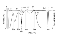
- the spectral distribution of the light emitted from the light source unit has a plurality of peaks, and the plurality of resonance wavelengths have a plurality of the peaks. It may be different from each wavelength of.
- the wavelength of the light at the peak of the spectral distribution tends to greatly affect the color tone of the light emitted from the vehicle lamp. Therefore, according to this vehicle lamp, it is possible to suppress the decrease in the transmittance of light having a wavelength that greatly affects the color tone of the emitted light in the metal lens, and it is possible to emit light having a desired color tone.
- all of the plurality of resonance wavelengths may not be included in the wavelength band of the light emitted from the light source unit.
- light of a desired color tone can be emitted as compared with the case where at least one resonance wavelength is included in the wavelength band of the light emitted from the light source unit.
- the metal lens may reduce the emission angle of the light from the light source portion transmitted through the metal lens.
- the spectral distribution of the light emitted from the light source unit may have a plurality of peaks, and the plurality of resonance wavelengths in the metal lens may be different from the wavelengths of the plurality of the peaks.
- the spectral distribution of the light emitted from the light source portion has a plurality of peaks, so that the color tone of the emitted light is different from that in the case where this spectral distribution has only one peak. It can be the desired color tone.
- the plurality of resonance wavelengths in the metal lens are different from the respective wavelengths of the plurality of peaks. The light of each wavelength at a plurality of peaks greatly affects the color tone of the light emitted from the vehicle lamp. Therefore, according to this vehicle lamp, it is possible to suppress the decrease in the transmittance of light having a wavelength that greatly affects the color tone of the emitted light in the metal lens, and it is possible to emit light having a desired color tone.
- the spectral distribution of the light emitted from the light source unit has a plurality of peaks
- at least one of the plurality of resonance wavelengths exceeds the shortest wavelength of each of the plurality of peaks and is less than the longest wavelength. It may be.
- the wavelength of the light having the minimum intensity between the peaks adjacent to each other may be the same as the at least one of the plurality of resonance wavelengths.
- the plurality of resonance wavelengths include a specific resonance wavelength included in the wavelength band of the light from the light source unit, and the spectrum of the light.
- the ratio of the intensity of the light at the particular resonance wavelength to the maximum intensity in the overall distribution may be 0.1 or less.
- FIG. 3 is a front view schematically showing a light source unit shown in FIG. 1.
- FIG. 3 is an enlarged front view showing a part of one main surface of the metal lens shown in FIG. 1. It is a figure which shows a part of a predetermined phase distribution in 1st Embodiment schematically. It is a figure which shows the part of the specific phase distribution in 1st Embodiment schematically.
- FIG. 3 shows the lamp for vehicle in 4th Embodiment in the same manner as FIG.
- FIG. 1 It is sectional drawing which shows schematic about the protection member and metal lens which concerns on 1st modification. It is a figure which shows the light distribution pattern for a low beam formed on the virtual vertical screen arranged at the position 25 m in front of the lighting fixture from the vehicle lighting fixture in 5th Embodiment. It is a figure which shows an example of the light distribution pattern in the 2nd modification. It is a figure which shows another example of the light distribution pattern in the 2nd modification. It is a figure which shows an example of the light distribution pattern in the 3rd modification. It is a figure which shows an example of the light distribution pattern in the 4th modification.
- FIG. 1 It is a figure which shows the spectral distribution of the light emitted from the light source part which concerns on 5th modification, and the transmittance distribution of the light of a metal lens in the same manner as FIG. It is a figure which shows schematic the spectral distribution of the light emitted from the light source part in 8th Embodiment, and the transmittance distribution of the light of a metal lens. It is a figure which shows the spectral distribution of the light emitted from the light source part which concerns on the 6th modification, and the transmittance distribution of the light of a metal lens in the same manner as FIG.
- FIG. 1 is a diagram showing a vehicle lamp according to the first embodiment of the present invention, and is a diagram schematically showing a vertical cross section of the vehicle lamp.
- the vehicle lamp 1 of the present embodiment is a headlight for an automobile. Headlights for automobiles are generally provided in each of the left and right directions in front of the vehicle. In the present specification, "right” means the right side in the traveling direction of the vehicle, and “left” means the left side in the traveling direction of the vehicle. Each of the left and right headlights has the same configuration except that the shape is substantially symmetrical in the left-right direction. Therefore, in the present embodiment, one of the headlights will be described.
- the vehicle lamp 1 of the present embodiment includes a housing 10, a light source unit 20, and a metal lens 30 as main configurations.
- the housing 10 of the present embodiment includes a lamp housing 11, a front cover 12, and a back cover 13 as main configurations.
- the front of the lamp housing 11 is open, and the front cover 12 is fixed to the lamp housing 11 so as to close the opening. Further, an opening smaller than the front is formed behind the lamp housing 11, and the back cover 13 is fixed to the lamp housing 11 so as to close the opening.
- the space formed by the lamp housing 11, the front cover 12 that closes the front opening of the lamp housing 11, and the back cover 13 that closes the rear opening of the lamp housing 11 is the light room R, and the light room R.
- a light source unit 20 and a metal lens 30 are housed therein.
- the back cover 13 is openable / closable or removable with respect to the lamp housing 11 for replacement of the light source portion 20 and the metal lens 30 through the rear opening of the lamp housing 11.
- the front cover 12 is made of a translucent material, and the light emitted from the light source unit 20 and transmitted through the metal lens 30 is transmitted through the front cover 12.
- the lamp housing 11 and the back cover 13 are made of, for example, resin.
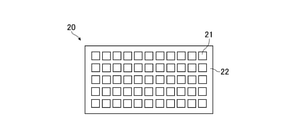
- FIG. 2 is a front view schematically showing the light source unit 20 shown in FIG.
- the light source unit 20 includes a plurality of light emitting elements 21 that emit light, and a circuit board 22 on which a plurality of light emitting elements 21 are mounted.
- the plurality of light emitting elements 21 are arranged in a matrix to form rows in the vertical direction and the horizontal direction, and emit light toward the front.
- Each of the plurality of light emitting elements 21 can individually change the amount of emitted light by the electric power supplied to each of the light emitting elements 21. Further, these light emitting elements 21 are phosphor type LEDs (Light Emitting Diodes) that emit white light, the light source unit 20 is a so-called LED array, and the light emitted from the light source unit 20 has a predetermined wavelength band. ing.
- the number and configuration of the light emitting elements 21 are not particularly limited.
- the light emitting element 21 may be configured to include a plurality of LEDs that emit light having different wavelengths from each other, or may be configured to include a plurality of LDs (Laser Diodes) that emit light having different wavelengths from each other. ..
- Such a light source unit 20 can emit light having a predetermined light distribution pattern by selecting a light emitting element 21 that emits light, and by changing the selection, the outer shape of the predetermined light distribution pattern can be obtained. Can be changed. Further, the light source unit 20 can adjust the intensity distribution of light in a predetermined light distribution pattern by adjusting the amount of light emitted from each light emitting element 21. That is, the light source unit 20 can emit light having a predetermined light distribution pattern according to the amount of light emitted from the plurality of light emitting elements 21, and can change the light distribution pattern of the emitted light. The light source unit 20 may not be able to change the light distribution pattern of the emitted light.
- the wavelength of the light L emitted from the light source unit 20 of the present embodiment is included in the wavelength band of visible light.
- the wavelength band of visible light is approximately 380 nm to 780 nm. Since the light L emitted from the light source unit 20 is the light emitted from the plurality of light emitting elements 21, the wavelength of the light emitted from each light emitting element 21 is substantially the same as the wavelength of the light L emitted from the light source unit 20. ..
- the wavelength of the light L does not have to be included in the wavelength band of visible light.
- the metal lens 30 of the present embodiment is a flat plate-shaped member, and is configured to adjust the divergence angle of light transmitted in the thickness direction.
- the metal lens 30 is arranged in front of the light source unit 20, and the light L emitted from the light source unit 20 is incident on one planar main surface 31s and emitted from the other planar main surface 32s. Therefore, the main surface 31s is an incident surface on which the light L from the light source unit 20 is incident, and the main surface 32s is an exit surface on which the light L emitted from the light source unit 20 incident on the main surface 31s is emitted.
- FIG. 3 is an enlarged front view showing a part of one main surface 31s of the metal lens 30 shown in FIG. 1.
- the main surface 31s has a plurality of cells 33 formed by being divided into two directions different from each other, and each cell 33 is provided with a nanostructure 35.
- the boundary between the adjacent cells 33 is shown by a broken line.
- only one cell 33 and one nanostructure 35 are designated with reference numerals, and the other cells 33 and nanostructures 35 are omitted from the reference numerals.
- the plurality of cells 33 are arranged over the entire main surface 31s, and the entire main surface 31s is a meta region in which the plurality of cells 33 including the nanostructure 35 are arranged.
- the shape of the metal lens 30 is a disk shape, and the plurality of cells 33 are arranged in the radial direction and the circumferential direction with respect to the center of gravity 31 g of the main surface 31s.
- the reference axis 36 orthogonal to the main surface 31s at the center of gravity 31g as a specific position intersects the light source unit 20.
- the light emitting element 21 of the light source unit 20 is arranged along a plane substantially perpendicular to the reference axis 36.
- the diameter of the metal lens 30 is 10 mm or more, for example, 50 mm. Therefore, the minimum width of the meta region is 10 mm or more.
- the region of the main surface 31s excluding the nanostructure 35 is a flat surface, and the nanostructure 35 is a protrusion extending from the main surface 31s toward the light source portion 20 side.
- Such a nanostructure 35 is configured as a part of the metal lens 30 by ultrafine processing on the main surface 31s, and is integrated with the metal lens 30.
- the arrangement of a plurality of cells 33 and the position and range of this meta area are not particularly limited.
- the meta region may be a part of the main surface 31s, or may be at least a part of the main surface 32s opposite to the light source unit 20 side. Further, the meta region may be at least a part of the main surface 31s and at least a part of the main surface 32s.
- the shape of the cell 33 shown in FIG. 3 is generally square, but is not particularly limited. Further, the sizes and shapes of the plurality of cells 33 may be different from each other. Further, the sizes of the meta lens 30 and the meta region are not particularly limited, and for example, the diameter of the meta lens 30 may be smaller than 10 mm. Further, the outer shape of the metal lens 30 is not particularly limited, and may be, for example, a quadrangular shape.
- the shape of the nanostructure 35 is a cylindrical shape, and the diameter is smaller than the longest wavelength of the light emitted from the light source unit 20.
- the width of the nanostructure 35 may be smaller than the longest wavelength of the light emitted from the light source unit 20, and the shape of the nanostructure 35 is not particularly limited.
- the shape of the nanostructure 35 may be a quadrangular prism shape or a C-shaped shape.
- the nanostructure 35 may be composed of a pair of quadrangular prisms or the like arranged at predetermined intervals.
- the shape of the nanostructure 35 in each cell 33 may be different.
- a plurality of nanostructures 35 may be provided in each cell 33, and the number of nanostructures 35 in each cell 33 may be different.
- examples of the material constituting the metal lens 30 include glass, resin and the like. The materials constituting the nanostructure 35 and the portion other than the nanostructure 35 may be the same or different.
- the cell 33 including such a nanostructure 35 can modulate the phase of the light L transmitted through the cell 33. Then, by adjusting the arrangement of the plurality of cells 33 and the size and shape of the nanostructure 35 in each cell 33, the phase distribution of the light L transmitted through the meta region can be changed, and the light L transmitted through the meta lens 30 is transmitted. The divergence angle of the white light L can be changed.
- the arrangement of the plurality of cells 33 and the size and shape of the nanostructure 35 in each cell 33 are adjusted so that the divergence angle of the light L becomes small and becomes a predetermined divergence angle. Therefore, it can be understood that the meta region is configured so that the phase of the light L is modulated so that the divergence angle of the light L becomes a predetermined divergence angle.
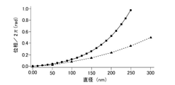
- FIG. 4 is a diagram schematically showing a part of a predetermined phase distribution 50 in the present embodiment, and is a diagram showing a predetermined phase distribution 50 in a vertical plane including the reference axis 36.
- the phase distribution of the reference light emitted from the metal lens 30 is a phase distribution in a virtual plane perpendicular to the reference axis 36, and in the present embodiment, the virtual plane is on the main surface 32s which is the exit surface of the metal lens 30. It is a phase distribution along the plane.
- the x-axis is the phase delay amount (rad)
- the y-axis is the distance from the intersection 32p of the reference axis 36 and the main surface 32s in the direction perpendicular to the reference axis 36
- r is the metal lens 30. It is a radius. As shown in FIG.
- the phase delay amount decreases and the phase delay increases as the distance from the reference axis 36 in the direction perpendicular to the reference axis 36 increases. It is a curve in which the rate of decrease in quantity increases.
- the predetermined phase distribution 50 on any plane including the reference axis 36 is a curve similar to the predetermined phase distribution 50 shown in FIG. Therefore, it can be understood that the predetermined phase distribution 50 is a phase distribution in which the phase delay amount decreases and the phase delay amount decrease rate increases as the distance from the reference axis 36 increases.
- the divergence angle of the light transmitted through the meta region and emitted from the metal lens 30 can be reduced. ..
- the phase of light is delayed by an integral multiple of 2 ⁇
- the wavefront of the light can be regarded as the same as the wavefront of light whose phase is not delayed. Therefore, even in the metal lens 30 of the present embodiment in which the meta region is configured so that the phase distribution of the reference light is a specific phase distribution consisting of the remainder obtained by dividing the predetermined phase distribution 50 by 2 ⁇ , the light L The divergence angle of can be reduced.
- the predetermined phase distribution 50 may be a phase distribution in which the phase delay amount decreases and the rate of decrease in the phase delay amount increases as the distance from the reference axis 36 increases, depending on the degree of adjustment of the divergence angle and the like. , The amount of delay in these phases and the rate of decrease in the amount of delay in the phase are adjusted.
- the reference axis 36 is not limited to one passing through the center of gravity 31g, and may be any one orthogonal to the meta region at a specific position in the meta region.
- FIG. 5 is a diagram schematically showing a part of the specific phase distribution 60 in the present embodiment, and is a diagram showing a part of the specific phase distribution 60 in the vertical plane including the reference axis 36. ..
- the x-axis is the phase delay (rad)
- the y-axis is the distance from the intersection 32p of the reference axis 36 and the main surface 32s in the direction perpendicular to the reference axis 36
- r is the metal lens 30. It is a radius.
- the width of this cycle becomes narrower as the distance from the reference axis 36 increases, the maximum width is about 400 ⁇ m, and the width of the cycle adjacent to the maximum cycle is about 100 ⁇ m.
- the minimum width is about 1 ⁇ m.
- the predetermined phase distribution 50 on any plane including the reference axis 36 is a curve similar to the predetermined phase distribution 50 shown in FIG. Therefore, the amount of phase delay in the specific phase distribution 60 on any plane including the reference axis 36 gradually repeats a change from a value as close to 2 ⁇ as possible to zero as the distance from the reference axis 36 increases. .. Therefore, it can be understood that the amount of phase delay in the specific phase distribution 60 repeats the above changes periodically as the distance from the reference axis 36 increases.
- the plurality of cells 33 are arranged so that two or more cells 33 are located between the peaks 61 adjacent to each other in the direction away from the center of gravity 31 g when viewed along the reference axis 36. That is, two or more cells 33 are arranged for one cycle of the above change.
- the shape of the nanostructure 35 is a cylindrical shape.
- the inventor arranges three or more cells 33 for one cycle of the above change, and the shape of the nanostructure 35 is a cylindrical shape, so that the energy of the light incident on the meta region is dealt with. It has been found that the ratio of the energy of the light emitted from the meta region can be 60% or more at the divergence angle corresponding to the specific phase distribution 60. Therefore, from the viewpoint of reducing the loss of light energy in the metal lens 30, such a configuration is preferable.
- the specific phase distribution 60 has three or more peaks 61. Further, when viewed along the reference axis 36, the number of cells 33 located between the peaks 61 adjacent to each other in the direction away from the center of gravity 31 g decreases as the distance from the center of gravity 31 g increases.
- the light L adjusted so that the divergence angle is reduced by the metal lens 30 is emitted toward the front of the vehicle through the front cover 12. Therefore, in the vehicle lamp 1 of the present embodiment, the size of the light distribution pattern of the emitted light can be easily set to a desired size. Further, as described above, the light source unit 20 can change the light distribution pattern of the emitted light. Therefore, according to the vehicle lamp 1, for example, a high beam and a low beam can be switched and emitted, or an ADB (Adaptive Driving Beam) can be emitted.
- ADB Adaptive Driving Beam
- the vehicle lamp 1 of the present embodiment includes a light source unit 20 and a metal lens 30.
- the metal lens 30 has a main surface 31s as a meta region.
- a plurality of cells 33 including a nanostructure 35 smaller than the longest wavelength of the light L emitted from the light source unit 20 are arranged on the main surface 31s, and the light L emitted from the light source unit 20 passes through the main surface 31s. ..
- the main surface 31s as a meta region changes the phase distribution of the light L transmitted through the main surface 31s.
- a projection lens in a vehicle lamp at least one of an incident surface and an emitted surface is generally a curved surface, and by adjusting the shape of the curved surface, the emission angle of light emitted from the light source unit can be adjusted. I'm adjusting. Therefore, in such a projection lens, a certain thickness is required to form the curved surface.
- the metal lens 30 in the vehicle lamp 1 of the present embodiment adjusts the arrangement of the plurality of cells 33 and the size of the nanostructure 35 in each cell 33 to adjust the phase distribution of the light L from the light source unit. Can be changed to adjust the emission angle of the light L.
- the curvature of the main surface 31s as a meta region is made smaller than the curvature of the curved surface of the projection lens, and even if the main surface 31s is made flat, for example, the light from the light source unit 20
- the divergence angle of the lens can be adjusted, making it thinner than the above projection lens. Therefore, according to the vehicle lamp 1 of the present embodiment, the size can be reduced as compared with the case where the emission angle of the light L from the light source unit 20 is adjusted by the projection lens.
- the lens by enlarging the lens, it becomes easier to increase the amount of light emitted from the lens.
- the minimum width of the main surface 31s as a meta region is 10 mm or more. Therefore, in the present embodiment, the light distribution pattern of the light emitted from the metal lens 30 can be easily set to the brightness required as the light distribution pattern of the light emitted from the headlight for the vehicle. Examples of the light distribution pattern of the light emitted from the vehicle headlight include a low beam and high beam light distribution pattern.
- FIG. 6 is a cross-sectional view schematically showing a metal lens in the present embodiment, and is a diagram schematically showing a cross section of the metal lens in the thickness direction.
- the entire main surface 31s as an incident surface on which the light L from the light source unit 20 is incident is a curved surface that is curved outward. In the main surface 31s curved in this way, the light L is refracted so that the divergence angle of the light L from the light source unit 20 becomes small.
- the entire main surface 32s as an emission surface from which the light L emitted from the light source unit 20 is emitted is a meta region in which a plurality of cells 33 including the nanostructure 35 are arranged, and the light source unit 20 incident on the main surface 31s.
- the light L from the light source passes through the meta region.
- the reference axis 36 is orthogonal to the main surface 32s at the center of gravity 32g as a specific position on the main surface 32s and intersects with the light source unit 20. Then, as in the first embodiment, in the meta region, the phase distribution of the reference light emitted from the metal lens 30 when the reference light parallel to the reference axis 36 is incident on the meta region is a predetermined phase distribution 50.
- the main surface 31s as an incident surface may be curved outward in a convex shape to refract the light L so that the divergence angle of the light L from the light source unit 20 becomes small, and a part of the light L may be bent outward. It may be configured to be curved in a convex shape toward the direction.
- the design of the meta region tends to be complicated.
- the light L from the light source unit 20 is incident on the main surface 32s as a meta region after the divergence angle is reduced by the main surface 31s which is a curved incident surface. Therefore, in the present embodiment, the divergence angle of the light L from the light source unit 20 incident on the meta region can be reduced as compared with the case where the main surface 31s is a flat surface. Therefore, according to the vehicle lamp 1 of the present embodiment, it is possible to suppress the design of the meta region from becoming complicated, and especially when the emission angle of the light L from the light source unit 20 is reduced as in the present embodiment. It is useful.
- the main surface 31s may be a meta region
- the main surface 32s may be curved outward in a convex shape
- the light L transmitted through the meta region may be emitted from the main surface 32s.
- the design of the meta region tends to be complicated. According to such a configuration, the angle for reducing the divergence angle of the light L can be reduced by the meta region as compared with the case where the main surface 32s is a flat surface, and the design of the meta region can be suppressed from becoming complicated.
- FIG. 7 is a cross-sectional view schematically showing the metal lens 30 in the present embodiment, and is a diagram schematically showing a cross section of the metal lens 30 in the thickness direction.
- a plurality of grooves 37 are provided on the planar main surface 31s as an incident surface on which the light L from the light source unit 20 is incident.
- the grooves 37 are exaggerated and described for the sake of clarity, and only one groove 37 is designated with a reference numeral, and the reference numerals of the other grooves 37 are omitted.
- Each groove 37 extends along a circle centered on the center of gravity 31 g, which is the center of the main surface 31s.
- the light L is diffracted so that the divergence angle of the light L from the light source unit 20 becomes small. That is, the shape, depth, width, position, and the like of the groove 37 are adjusted so that the light L is diffracted in this way, and it can be understood that the main surface 31s diffracts the light L in this way.
- the entire main surface 32s from which the light L emitted from the light source unit 20 is emitted is a meta region in which a plurality of cells 33 including the nanostructure 35 are arranged, and the light L from the light source unit 20 is transmitted through the meta region. do.
- the reference axis 36 is orthogonal to the main surface 32s at the center of gravity 32g as a specific position on the main surface 32s and intersects with the light source unit 20. Then, as in the first embodiment, in the meta region, when the reference light parallel to the reference axis 36 is incident on the meta region, the phase distribution of the reference light emitted from the meta lens has a predetermined phase distribution 50. It is configured to have a specific phase distribution 60 consisting of a remainder divided by 2 ⁇ .
- the main surface 31s as an incident surface may be provided with a plurality of grooves 37, and the light L may be diffracted so that the divergence angle of the light L from the light source unit 20 becomes small. Etc. are not restricted. Further, the groove 37 may be provided on the curved main surface 31s.
- the light L from the light source unit 20 is incident on the meta region after the divergence angle is reduced by the main surface 31s which is the incident surface. Therefore, the angle at which the divergence angle of the light L incident on the main surface 31s can be reduced by the meta region can be reduced as compared with the case where the main surface 31s on which the light L from the light source unit 20 is incident is a flat surface. Therefore, according to the vehicle lamp 1 of the present embodiment, it is possible to suppress the design of the meta region from becoming complicated, and especially when the emission angle of the light L from the light source unit 20 is reduced as in the present embodiment. It is useful.
- a plurality of grooves 37 are provided on the main surface 31s in which the main surface 31s is curved outward in a convex shape, and the main surface 31s is the light source unit 20.
- the light L from may be diffracted.
- at least a part of the main surface 31s is a meta region, and the light L transmitted through the meta region may be diffracted by the main surface 32s so that the divergence angle becomes small.
- the angle for reducing the divergence angle of the light L can be reduced by the meta region as compared with the case where the main surface 32s is a flat surface, and the design of the meta region can be suppressed from becoming complicated. ..
- FIG. 8 is a diagram showing the vehicle lamp 1 in the present embodiment in the same manner as in FIG. In FIG. 8, the description of the housing 10 and the light source unit 20 is omitted. As shown in FIG. 8, the vehicle lamp 1 of the present embodiment is different from the vehicle lamp 1 of the first embodiment in that it further has a protective member 40 having light transmission.
- the protective member 40 of the present embodiment includes a main body portion 41 and ribs 42.
- the main body 41 is a disk-shaped member, and one main surface 43s is arranged so as to face the main surface 31s of the metal lens 30 at a predetermined distance. In the direction parallel to the reference axis 36, the entire main surface 31s as a meta region overlaps with the main body 41.
- the rib 42 is provided on the main surface 43s of the main body 41 and projects toward the metal lens 30 side. The rib 42 extends along the outer edge of the main body 41 over the entire circumference. The inner peripheral surface of the rib 42 is adhered to the outer peripheral surface of the metal lens 30 over the entire circumference, and the protective member 40 is fixed to the metal lens 30.
- Such a protective member 40 covers the main surface 31s in a non-contact manner with the main surface 31s as a meta region, and the main surface 31s is exposed in the closed space 45 formed by the protective member 40 and the meta lens 30.
- the main body 41 and the rib 42 are integrally formed, and examples of the material constituting the protective member 40 include glass, resin, and the like.
- the light L emitted from the light source unit 20 passes through the main body portion 41 of the protective member 40 and is incident on the metal lens 30, and the divergence angle of the light L is adjusted by the metal lens 30 to adjust the divergence angle.
- the light L is emitted toward the front of the vehicle through the front cover 12.
- the protective member 40 covers the main surface 31s as a meta region. Therefore, it is possible to prevent dust and the like from entering between the respective nanostructures 35, dust and the like from adhering to the nanostructures 35, and damage to the nanostructures 35, and the light L from the light source unit 20.
- the divergence angle of can be adjusted appropriately.
- the rib 42 of the protective member 40 may be provided with a communication portion such as a hole for communicating the closed space 45 with the outside.
- a communication portion such as a hole for communicating the closed space 45 with the outside.
- the protective member 40 is not provided with such a hole. Is preferable.
- the protective member 40 may be in contact with the nanostructures 35.
- the main body 41 of the protective member 40 may fill the space between the nanostructures 35.
- FIG. 9 is a cross-sectional view schematically showing the protective member 40 and the metal lens 30 according to the first modification, and is a diagram schematically showing a part of the cross section of the protective member 40 and the metal lens 30 in the thickness direction. Is. Further, in FIG. 9, for the sake of easy viewing, only one nanostructure 35 is designated with a reference numeral, and the reference numerals of the other nanostructures 35 are omitted. In this case, the refractive index of the protective member 40 is lower than the refractive index of the metal lens 30. Even with such a configuration, the divergence angle of the light L can be adjusted by the metal lens 30.
- Coma aberration is an aberration in which a point image on the image plane does not form a single point, but spreads and forms a comet-like tail.
- light does not diffuse radially from the point image to the periphery of the point image, but extends in a certain direction from the point image. As a result, it can be understood that the divergence angle of light is widened by coma aberration.
- the meta region of the present embodiment widens the divergence angle of the light L transmitted through the meta region due to the coma aberration as compared with the case where the above coma aberration does not occur. Due to the expansion of the divergence angle of the light L, the light distribution pattern formed by the light L transmitted through the meta region is projected to the outside of the vehicle lamp 1 in a expanded state as compared with the case where coma aberration does not occur.
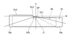
- FIG. 10 is a diagram showing a light distribution pattern for a low beam formed on a virtual vertical screen arranged at a position 25 m in front of the left and right vehicle lamps 1 in the present embodiment.
- the light distribution pattern 70 projected from the metal lens 30 in which coma aberration is generated is shown by a solid line.
- the light distribution pattern 80 projected from the metal lens in which coma aberration does not occur is shown by a broken line.
- the upper end and the lower end of the light distribution pattern 80 are shown inside the upper end and the lower end of the light distribution pattern 70, but the light distribution pattern 80 is shown.
- the upper end and the lower end are located at the same positions as the upper end and the lower end of the light distribution pattern 70. It is assumed that the centers of the light distribution patterns 70 and 80 are located at the same position.
- S indicates a horizontal line
- C indicates a reference axis that passes through the center of the light distribution pattern 70 in the left-right direction and extends in the front-rear direction of the vehicle orthogonal to the light distribution pattern 70
- V indicates a reference axis with respect to the reference axis C.
- the light distribution pattern 70 has cut-off line CL1, CL2, and CL3 at the upper end.
- the cut-off line CL1 is provided on the opposite side of the cut-off line CL3 with the cut-off line CL2 as a reference.
- the intersection of the cut-off line CL1 and the cut-off line CL2 is referred to as an elbow point EP.
- the elbow point EP is located below the horizon S and on the vertical line V.
- the elbow point EP may be located below the horizon S and near the vertical line V.
- the cut-off line CL1 extends horizontally from the elbow point EP to the right side, which is one side in the left-right direction of the vehicle.
- the cut-off line CL2 extends diagonally upward to the left in the vertical and horizontal directions of the vehicle from the elbow point EP.
- the end of the cut-off line CL2 on the side opposite to the elbow point EP side is located above the horizon S.
- the cut-off line CL3 extends horizontally from the above-mentioned end of the cut-off line CL2 to the left side in the left-right direction of the vehicle.
- the light amount is the largest in the hot zone HZL located near the elbow point EP, and gradually decreases as the distance from the hot zone HZL increases.
- a coma aberration that extends a point image in the light distribution pattern 70 from the inside of the light distribution pattern 70 toward the outside of the light distribution pattern 70 in the left-right direction of the light distribution pattern 70 is generated.
- the phase distribution of the light L transmitted through the region is changed.
- the meta region of the present embodiment widens the divergence angle of the light L due to the coma aberration in the left-right direction of the light distribution pattern 70 formed by the light L, as compared with the case where the coma aberration does not occur.
- the light distribution pattern 70 is wider than the light distribution pattern 80 in the left-right direction of the 70.
- the light distribution pattern 70 a part of the light distribution pattern 70 between the V line and the left end of the light distribution pattern 70 is set as a region 70a, and the light distribution pattern 70 between the V line and the right end of the light distribution pattern 70 The remaining part is the region 70b.
- the meta region widens the divergence angle of the light L forming the region 70a to the left from the reference axis C of the light distribution pattern 70 due to coma aberration.
- the divergence angle of the light L forming the region 70b is widened to the right from the reference axis C of the light distribution pattern 70 by coma aberration.
- the light distribution pattern 70 spreads to the left side where the left end of the light distribution pattern 80 is outside in the region 70a, and spreads to the right side where the right end of the light distribution pattern 80 is outside in the region 70b. It becomes.
- the divergence angle of the light L forming the region 70a and spreading to the left and the divergence angle of the light L forming the region 70b and spreading to the right are the same.
- the spread amount of each of the right end and the left end of the light distribution pattern 70 can be the same, and the design of the metal lens 30 can be facilitated as compared with the case where the spread amount is not the same.
- the phase distribution of the light L transmitted through the meta region is changed so that coma aberration occurs, and the light L transmitted through the meta region is compared with the case where coma aberration does not occur.
- the divergence angle of the light distribution pattern 70 is widened in the left-right direction.
- the emission angle of the light L can be widened by adjusting the arrangement of the plurality of cells 33 and the size and shape of the nanostructure 35 in each cell 33.
- the divergence angle can be further widened in the left-right direction due to the elongation of light L due to coma aberration. Therefore, according to the vehicle lighting tool 1 of the present embodiment, the light distribution pattern 70 is further in the left-right direction than the light distribution pattern projected from the metal lens 30 in which the divergence angle of the light L is widened without causing coma. Can spread.
- a projection lens as described above having a curved surface is designed so that coma aberration is suppressed. Therefore, when a projection lens is used, the spread of the divergence angle of the light from the light source unit is suppressed by the projection lens, and the spread of the light distribution pattern projected to the outside of the vehicle lamp is suppressed.
- the meta region of the meta lens 30 configured as the projection lens of the present embodiment the emission angle of the light L from the light source unit 20 is widened as described above by generating coma, so that the light distribution pattern 70 may be wider than the light distribution pattern projected from the projection lens.
- both a projection lens and an additional lens are used in order to widen the light distribution pattern.
- the metal lens 30 of the present embodiment it is not necessary to adjust the relative position between the projection lens and the lens as compared with the case where the light distribution pattern is spread by the projection lens and the lens different from the projection lens. The number of points can be reduced, and the weight of the vehicle lamp 1 can be reduced. Further, as compared with the case where the light divergence angle is widened by the above-mentioned projection lens and the above-mentioned another lens, in the vehicle lamp 1 of the present embodiment, the divergence angle of the light L can be widened by one metal lens 30, and the size is small. Can be changed.
- the spread amount of the light distribution pattern 70 is adjusted by the spread amount of the divergence angle of the light L, the spread amount of the divergence angle is adjusted by the above-mentioned elongation of the light L which is the degree of coma aberration, and the elongation of the light L is plural. It is adjusted by the arrangement of the cells 33 and the size and shape of the nanostructure 35 in each cell 33. Since the degree of freedom in designing the metal lens 30 is increased in this way, in the vehicle lamp 1 of the present embodiment, the light distribution pattern 70 has a light distribution pattern 70 as compared with a projection lens in which coma aberration is unintentionally generated due to processing accuracy. The amount of spread can be easily controlled.
- the degree of freedom of the spread amount of the light distribution pattern depends on the shape of the projection lens and the light amount distribution in the light distribution pattern projected by the projection lens. Will be limited. However, in the vehicle lamp 1 of the present embodiment, by adjusting the degree of coma aberration described above, the degree of freedom of the spread amount of the light distribution pattern 70 can be improved as compared with the projection lens that intentionally generates coma aberration. ..
- the light distribution pattern 70 can be easily expanded in the left-right direction by arranging the plurality of cells 33 and adjusting the size and shape of the nanostructure 35 in each cell 33.
- the metal lens 30 can be easily produced as compared with the production of a projection lens in which coma aberration is intentionally generated so that the light distribution pattern 70 spreads in the left-right direction.
- Examples of aberrations in which light is diverged other than the coma aberration used in the metal lens 30 of the present embodiment include spherical aberration, astigmatism, and image plane aberration.
- the light on the image plane may diffuse radially from the reference point image to the periphery of the point image. Therefore, with these three aberrations, the blur of the image spreads not only outside the light distribution pattern but also inside the light distribution pattern as in coma. Therefore, the light distribution pattern spread by any one of these three aberrations does not spread efficiently as compared with the light distribution pattern spread by coma aberration.
- the divergence angle of the light L is widened only in the left-right direction in the direction away from the reference axis C of the light distribution pattern 70 due to coma aberration, so that it is compared with the other three aberrations. Therefore, it becomes easy to efficiently spread the light distribution pattern 70 in the left-right direction, and the spreading direction can be defined in one direction. Further, with the three aberrations, the above-mentioned diffusion may cause blurring of brightness at the left and right edges of the light distribution pattern.
- the direction in which the light distribution pattern is spread is controlled to be outside the light distribution pattern in the left-right direction due to coma aberration.
- the amount of light can be gradually reduced from the inside to the outside around the left and right edges of the light distribution pattern, and the brightness at the left and right ends of the light distribution pattern is higher than that of the other three aberrations. Blurring can be suppressed.
- the light is extended in a certain direction from the point image on the image plane due to coma, and the amount of extension of the light is the spread angle from the point image on the image plane to the outermost angle of the comet-like divergent light spreading from the point image.
- the amount of light in the light extended by coma is the largest in the point image, and gradually decreases as the distance from the point image increases.
- the amount of light at the left and right ends of the spreading light distribution pattern 70 gradually decreases from the center side to the outside of the light distribution pattern 70, and uneven light distribution occurs at the left and right ends of the light distribution pattern 70. Can be suppressed.
- the amount of light elongation may be about 15% of the spread angle of the light forming the point image on the image plane, and is 50% of the spread angle. If there is, it is very effective.
- the light distribution pattern 70 has been described as a light distribution pattern for a low beam, it may be a light distribution pattern for a high beam.
- the meta region In the meta region, coma aberration is suppressed in the central portion of the light distribution pattern 70, and the divergence angle may be widened toward the end of the light distribution pattern 70. As a result, the amount of light in the center is maintained, and the driver's field of vision is widened. Further, the meta region may widen one of the divergence angle of the light L forming the region 70a and spreading to the left and the divergence angle of the light L forming the region 70b and spreading to the right. As a result, only one of the right end and the left end of the light distribution pattern 70 can be spread. Further, the meta region may form a region 70a and widen the divergence angle of at least a part of the light L spreading to the left.
- the meta region may form a region 70b and widen the divergence angle of at least a part of the light L spreading to the right. As a result, at least a part of the right end of the light distribution pattern 70 can be expanded.
- a vehicle lamp 1 provided with a meta lens 30 having a meta region that changes the phase distribution of the light L so as to generate coma has been described by taking the fifth embodiment as an example. Not limited.
- the second modification, the third modification, and the fourth modification, which are modifications of the vehicle lamp 1, will be described below.
- FIG. 11 is a diagram showing an example of the light distribution pattern in the second modification
- FIG. 12 is a diagram showing another example of the light distribution pattern in the second modification.
- the meta region of this modification forms a divergence angle of light L that forms a region 70a and spreads to the left from the reference axis C of the light distribution pattern 70, and forms a region 70b and spreads to the left from the reference axis C of the light distribution pattern 70.
- One of the divergence angles of the light L may be larger than the other.
- one of the spread amount at the right end of the light distribution pattern 70 and the spread amount at the left end of the light distribution pattern 70 becomes larger than the other.
- the meta region forms the region 70a and forms the divergence angle of the light L spreading to the left from the reference axis C of the light distribution pattern 70 to form the region 70b, and the light L spreads to the right from the reference axis C of the light distribution pattern 70.
- the light distribution pattern 70 spreads wider to the left end than to the right end as shown in FIG.
- the irradiation range of the light L on an object such as a pedestrian or a road sign located on the sidewalk on the traveling lane side can be expanded.
- the meta region forms the region 70b and the emission angle of the light L extending to the right from the reference axis C of the light distribution pattern 70 forms the region 70a, and the light spreads to the left from the reference axis C of the light distribution pattern 70.
- the light distribution pattern 70 spreads widely to the right end rather than the left end as shown in FIG.
- the irradiation range of the light L on an object such as a pedestrian located on the sidewalk on the oncoming lane side can be expanded. Therefore, the driver of the vehicle may be able to more easily see the object located on the side where the light distribution pattern is widened.
- FIG. 13 is a diagram showing an example of a light distribution pattern in the third modification.
- the light distribution pattern 70 of this modification is configured by overlapping the light distribution pattern 71 projected from the vehicle lighting tool 1 on the left side and the light distribution pattern 73 projected from the vehicle lighting tool 1 on the right side.
- the light distribution pattern 71 is provided with hatching extending diagonally upward to the left
- the light distribution pattern 73 is provided with hatching extending diagonally upward to the right.
- the left end of the light distribution pattern 71 is located outside the left end of the light distribution pattern 73.
- the right end of the light distribution pattern 73 is located outside the right end of the light distribution pattern 71.
- the light distribution pattern 80 is formed by overlapping the light distribution patterns projected from the left and right vehicle lamps 1.
- the light distribution pattern 80 is not hatched in order to easily distinguish it from the light distribution patterns 71 and 73.
- the meta region of the vehicle lamp 1 on the left side widens the divergence angle of the light L to the left from the optical axis, which is the direction away from the reference axis C of the light distribution pattern 70 due to coma.
- the left end of the light distribution pattern 71 extends to the left of the left end of the light distribution pattern 80.
- the meta region of the vehicle lamp 1 on the right side widens the divergence angle of the light L to the right from the optical axis which is the direction away from the reference axis C of the light distribution pattern 70 due to coma.
- the left end of the light distribution pattern 73 extends to the right of the right end of the light distribution pattern 80.
- the light distribution pattern 70 can be expanded to the left and right. ..
- the metal lens 30 for the left side is replaced with another metal lens 30 for the left side having a different degree of coma aberration from the metal lens 30 for the left side before replacement, so that the light distribution pattern is in the left direction. You can adjust the spread.
- FIG. 14 is a diagram showing an example of a light distribution pattern in the fourth modification.
- S1 is a line parallel to the horizontal line S and passes through the center of the light distribution pattern 70.
- a part of the light distribution pattern 70 between the S1 line and the upper end of the light distribution pattern 70 is set as a region 70c, and the rest of the light distribution pattern 70 between the S1 line and the lower end of the light distribution pattern 70.
- the light distribution pattern 70 is for a low beam, and it is necessary to fix the position of the cut line.
- the meta region is upward from the optical axis, which is a direction in which the divergence angle of the light L forming the region 70c is separated from the reference axis C of the light distribution pattern 70 due to coma when the metal lens 30 is viewed from the horizontal direction.
- the divergence angle of the light L forming the region 70d is widened downward from the optical axis, which is the direction away from the reference axis C of the light distribution pattern 70 due to coma.
- the light distribution pattern 70 becomes a light distribution pattern in which the lower end of the light distribution pattern 80 spreads downward in the region 70d.
- the meta region uses coma aberration to determine the divergence angle of the light L forming the region 70c when the metal lens 30 is viewed from the horizontal direction. It may be expanded upward from the optical axis, which is a direction away from the reference axis C of 70. As a result, the light distribution pattern 70 becomes a light distribution pattern in which the upper end of the light distribution pattern 80 spreads upward in the region 70c.
- a coma aberration that extends the point image in the light distribution pattern 70 from the inside of the light distribution pattern 70 toward the outside of the light distribution pattern 70 in the vertical direction of the light distribution pattern 70 occurs.
- the phase distribution of the light L transmitted through the light L is changed.
- the meta region widens the divergence angle of the light L in the vertical direction of the light distribution pattern in the direction away from the reference axis C of the light distribution pattern 70 as compared with the case where coma aberration does not occur, as compared with the light distribution pattern 80.
- the light distribution pattern 70 is also extended in the vertical direction, which is the height direction of the light distribution pattern. In this case, the driver of the vehicle may be able to easily see an object such as a guide sign or a road surface.
- the meta region forms the end side of the light distribution pattern 70 in the left-right direction, and forms the end side of the light distribution pattern 70 in the vertical direction with the divergence angle of the light L spreading in the left-right direction from the reference axis C of the light distribution pattern 70. It is wider than the divergence angle of the light L spreading in the vertical direction from the reference axis C of the light distribution pattern 70.
- the spread amount of each of the left and right ends of the light distribution pattern 70 becomes larger than the spread amount of the lower end of the light distribution pattern 70, and the light distribution pattern 70 has a light distribution pattern without changing the light amount of the light emitted from the metal lens 30. It spreads more in the left-right direction than in the up-down direction of 70.
- the driver's field of view can be widened in the left-right direction rather than the up-down direction by the light distribution pattern.
- the driver of the vehicle can see pedestrians and objects such as road signs. It may be easier to see.
- the meta region may not widen the divergence angle of the light L forming the lower end side of the light distribution pattern 70, or may widen the divergence angle of the light L forming the upper end side of the light distribution pattern 70.
- the meta region may widen the divergence angle of the light L forming the end side of the light distribution pattern 70 in the vertical direction from the divergence angle of the light L forming the end side of the light distribution pattern 70 in the left-right direction.
- the light distribution pattern 70 spreads more in the vertical direction than in the horizontal direction of the light distribution pattern 70.
- light such as sunlight is emitted from the outside of the vehicle lamp 1 through the front cover 12 to the housing of the vehicle lamp 1. It may be incident on the inside of 10.
- the light incident on the inside of the housing 10 is incident on the main surface 32s in the metal lens 30, emitted from the main surface 31s toward the light source unit 20, and travels in the direction opposite to the light L from the light source unit 20 to be the light source unit. It may be focused on 20.
- the light source unit 20 may be deteriorated due to the light collection.
- the meta region of the present embodiment suppresses light collection by a bending force, and the bending force will be described below.
- the longest wavelength of visible light contained in light is 660 nm
- the shortest wavelength of infrared light contained in light is 1000 nm
- the wavelength ratio of each light in this case is 1: 1.5.
- Bending force refers to the force that the refracting lens and the meta region bend the light that passes through them. The smaller the bending force, the smaller the bending angle of the light transmitted through each, and the more the focusing of light is suppressed.
- Acrylic or polycarbonate is mentioned as the main material of the refracting lens.
- the refractive index of the acrylic refracting lens is 1.489 with respect to visible light and 1.483 with respect to infrared light.
- the refractive index of the refractive index made of polycarbonate is 1.579 with respect to visible light and 1.568 with respect to infrared light.
- the bending force of the refracting lens is proportional to the "refractive index -1". Therefore, in a refracting lens made of acrylic, if the bending force of the refracting lens that bends visible light is 1, the bending force of the refracting lens that bends infrared light is approximately 0.98. Further, in a refracting lens made of polycarbonate, assuming that the bending force of the refracting lens that bends visible light is 1, the bending force of the refracting lens that bends infrared light is approximately 0.98.
- the bending force of the refracting lens that bends infrared light is approximately 0.98 times the bending force of the refracting lens that bends visible light.
- the bending force of the refracting lens that bends the infrared light is almost the same as the bending force of the refracting lens that bends the visible light
- the bending angle of the infrared light is almost the same as the bending angle of the visible light
- the infrared light The focal distance of the refracting lens that bends is approximately the same as the focal distance in the case of visible light. Therefore, the refracting lens makes it easy to collect infrared light.
- the phase distribution of the light transmitted through the meta region is changed by the meta region as described above. Since the phase represents the advance and delay of the wavefront of light, the light given the phase distribution has a slope on the wavefront. Since the light travels in a direction perpendicular to the wavefront, the wavefront of the phase-modulated light in the meta region tilts in a direction different from the original traveling direction due to the above effect, and the traveling direction of the light is bent. Therefore, the bending force of the meta region that bends the light transmitted through the meta region is substantially proportional to the value of the product of the phase modulation amount of the light and the wavelength of the light. As described above, the meta region changes the phase distribution of the light transmitted through the meta region.
- This phase distribution changes according to the arrangement of the plurality of cells 33 and the size and shape of the nanostructure 35 in each cell 33.
- the meta region changes the phase distribution of the light transmitted through the meta region.
- the phase modulation amount of the light is changed by the change.
- the ratio of the phase modulation amount of visible light to the phase modulation amount of infrared light is set to 4: 1 by the above adjustment, and the longest wavelength of visible light and the infrared light The ratio to the shortest wavelength is 1: 1.5. Therefore, in this case, the ratio of the bending force of the meta region that bends visible light to the bending force of the meta region that bends infrared light is 1: 0.3.
- the meta region changes the phase distribution of the light transmitted through the meta region by the above adjustment, the phase modulation amount of the light is changed by the change, and the visible light transmitted through the meta region is changed by this change.
- the bending force of the meta region that bends the infrared light that passes through the meta region is smaller than the bending force of the bending meta region.
- the bending angle of infrared light is smaller than the bending angle of visible light, so that the meta region is of infrared light. Condensation can be suppressed. Therefore, in the meta region, visible light is focused on the light source unit 20, the focusing of infrared light is suppressed, and infrared light is transmitted.
- the bending force of the meta region that bends infrared light is smaller than the bending force of the refracting lens that bends the infrared light by the above adjustment. Therefore, the bending angle of the infrared light due to the meta region is smaller than the turning angle of the infrared light due to the refracting lens.
- the focal length of the refracting lens that bends visible light is 50 mm
- the focal length of the refracting lens that bends infrared light is approximately 0 from the focal length that bends visible light due to the above-mentioned bending force ratio of the refracting lens. .1 mm off.
- the focal length of the metal lens 30 including the meta region that bends visible light is 50 mm as described above
- the focal length of the metal lens 30 including the meta region that bends infrared light is the meta region. It deviates approximately 100 mm from the focal length of the metal lens 30 including the meta region that bends visible light due to the above bending force ratio.
- the bending force of the meta region to bend the infrared light is smaller than that of the refracting lens
- the bending angle of the infrared light due to the meta region is smaller than the bending angle of the infrared light due to the refracting lens, so that the meta region is smaller than that of the refracting lens.
- the meta region can suppress the focusing of infrared light.
- the ratio of the bending force of the meta region that bends visible light to the bending force of the meta region that bends infrared light is approximately 1: 0.9, that is, the bending force of the meta region that bends infrared light is visible. It is approximately 0.9 times the bending force of the meta region that bends light.
- phase modulation amount of visible light and the infrared light when the ratio of the bending force of the meta region that bends visible light to the bending force of the meta region that bends infrared light is approximately 1: 0.9.
- the ratio with the phase modulation amount will be described.
- the ratio of the phase modulation amount of visible light to the phase modulation amount of infrared light is 1: X.
- the ratio of each wavelength of visible light and infrared light is 1: 1.5 as described above.
- the ratio of the bending force of the meta region that bends visible light to the bending force of the meta region that bends infrared light is approximately 1: 0.9 as described above.
- the bending force of the meta region that bends each of the visible light and the infrared light is roughly proportional to the value of the product of the phase modulation amount and the wavelength. Therefore, X is 0.6, and the phase modulation amount of infrared light is 0.6 times the phase modulation amount of visible light.
- the phase modulation amount of infrared light is visible light. It is preferable that the amount of phase modulation is less than 0.6 times.
- the bending force of the refracting lens that bends infrared light is approximately 0.98 times the bending force of the refracting lens that bends visible light, and the bending force of the meta region that bends infrared light is visible light. It is less than 0.9 times the bending force of the bending meta region. Comparing the bending force of the meta region that bends infrared light and the bending force of the refracting lens that bends infrared light based on the respective bending forces that bend visible light, the bending force of the meta region that bends infrared light The bending force is smaller than the bending force of the refracting lens that bends the infrared light. Therefore, the meta region can suppress the focusing of infrared light more than the refracting lens.
- FIG. 15 is a diagram showing the relationship between the diameter of the nanostructure 35 and the respective phase modulation amounts of visible light having the longest wavelength of 660 nm and infrared light having the shortest wavelength of 1000 nm.
- the solid line shows the relationship between the diameter of the nanostructure 35 and the phase modulation amount of visible light
- the broken line shows the relationship between the diameter of the nanostructure 35 and the phase modulation amount of infrared light.
- the shape of the nanostructure 35 may be cylindrical, and the diameter range of the cylindrical nanostructure 35 may be a diameter corresponding to this range, for example, from 0 nm to 250 nm. Suitable. In the present embodiment, it is more preferable that the diameter range of the nanostructure 35 is, for example, from 100 nm to 250 nm, and a plurality of nanostructures 35 having a diameter within this range are arranged.
- the phase modulation amount of visible light is 0.5 ⁇ radian. Therefore, the meta region suppresses the focusing of infrared light and transmits infrared light.
- the shape of the nanostructure 35 is a cylinder, the longer the wavelength of the light to be focused, the smaller the slope of the graph shown in FIG. 15, and the wider the range of the diameter of the nanostructure 35.
- the meta region of the present embodiment changes the phase distribution of the light transmitted through the meta region, and the meta region is larger than the bending force of the meta region that bends the visible light contained in the light transmitted through the meta region.
- the bending force of the meta region that bends the infrared light contained in the transmitted light is reduced.
- the meta region changes the phase distribution of the light transmitted through the meta region.
- This phase distribution changes according to the arrangement of the plurality of cells 33 and the size and shape of the nanostructure 35 in each cell 33. Therefore, by adjusting these, the meta region changes the phase distribution of the light transmitted through the meta region, and the infrared light contained in the light is more than the bending force of the meta region that bends the visible light contained in the light. Reduce the bending force of the meta region that bends. The smaller the bending force, the smaller the bending angle of the light transmitted through the meta region, and the more the focusing of the light is suppressed.
- the vehicle lighting tool 1 has infrared light contained in the sunlight. Since the bending angle of the above bending force is smaller than the bending angle of visible light in sunlight, the meta region can suppress the focusing of infrared light traveling to the light source unit 20 as compared with the projection lens. When the light collection of infrared light is suppressed, the deterioration of the light source unit 20 due to the light collection of infrared light can be suppressed as compared with the projection lens.
- the influence of the deterioration of the light source unit 20 on the light L emitted from the light source unit 20 is suppressed, and a predetermined light distribution pattern can be projected.
- the shape of the nanostructure 35 a cylindrical shape, even if the visible light from the light source unit 20 is randomly polarized light, the visible light can be efficiently bent.
- a vehicle lamp 1 provided with a meta lens 30 having a meta region having a meta region in which the bending force for bending infrared light is smaller than the bending force for bending visible light has been described by taking the sixth embodiment as an example. Is not limited to this. A modification of the sixth embodiment will be described below.
- sunlight is used as the light incident on the inside of the vehicle lamp 1 from the outside of the vehicle lamp 1, but the light needs to be limited to the sunlight. Instead, it may be infrared light or visible light incident on the inside of the vehicle lamp 1 from the outside of the vehicle lamp 1. Further, as an example of a wavelength ratio of 1: 1.5, the longest wavelength of visible light is 660 nm and the shortest wavelength of infrared light is 1000 nm. However, if the ratio is 1: 1.5, visible light is used. The respective wavelengths of the infrared light and the infrared light are not particularly limited.
- the light distribution pattern projected from the vehicle lighting fixture 1 may be a light distribution pattern for a low beam or a light distribution pattern for a high beam.
- FIG. 16 is a diagram showing a vehicle lamp according to the present embodiment in the same manner as in FIG.
- FIG. 17 is a diagram schematically showing the spectral distribution of the light emitted from the light source unit 20 and the transmittance distribution of the light of the metal lens 30 in the present embodiment.
- the horizontal axis is the wavelength
- the first vertical axis is the relative intensity based on the maximum intensity
- the second vertical axis is the relative transmittance based on the maximum transmittance. be.
- the spectral power distribution is shown by a thin line
- the transmittance distribution is shown by a thick line.
- the wavelength band of the light L emitted from the light source unit 20 is approximately 380 nm to 780 nm.
- the spectral distribution 90 of the light L has four peaks 91, 92, 93, 94.
- the wavelengths 91w, 92w, 93w, and 94w at the peaks 91, 92, 93, and 94 become longer in the order of wavelength 91w, wavelength 92w, wavelength 93w, and wavelength 94w.
- the wavelength 91w is approximately 410 nm
- the wavelength 92w is approximately 460 nm
- the wavelength 93w is approximately 530 nm
- the wavelength 94w is approximately 620 nm.
- the wavelength 91w is the shortest and the wavelength 94w is the longest.
- the wavelengths 91w, 92w, 93w, 94w at these peaks 91, 92, 93, 94 are included in the wavelength band of visible light.
- the spectral power distribution 90 may have a peak not included in the wavelength band of visible light. Further, the number of peaks in the spectral distribution 90 is not limited, and for example, the spectral distribution 90 may not have peaks.
- the spectral distribution of the light emitted from each light emitting element 21 is substantially the same as the spectral distribution 90 shown in FIG. be.
- sunlight L2 enters the light chamber R through the front cover 12 and passes through the metal lens 30 to the light source unit. 20 may be irradiated.
- the metal lens 30 reduces the divergence angle of the light L from the light source unit 20 passing through the metal lens 30. Therefore, the sunlight L2 transmitted through the metal lens 30 is condensed and irradiated to the light source unit 20.
- FIG. 18 is a diagram schematically showing the spectral distribution of sunlight L2 near the ground surface and the light transmittance distribution of the metal lens 30 of the present embodiment.
- the horizontal axis is the wavelength
- the vertical axis is the relative intensity based on the maximum intensity
- the second vertical axis is the relative transmittance based on the maximum transmittance.
- the spectral distribution is shown by a thin line
- the transmittance distribution in the range of 300 nm to 2500 nm is shown by a thick line.
- the sunlight L2 includes infrared light as well as visible light.
- a phenomenon may occur in which the transmittance of light of a specific wavelength becomes extremely lower than the transmittance of light of other wavelengths. It is known that there are multiple specific wavelengths. These specific wavelengths are wavelengths at which the light transmittance in the metal lens peaks, and are called resonance wavelengths. These resonance wavelengths are determined according to the size and shape of the nanostructure in each cell, the refractive index of the material constituting the nanostructure, and the like. In the present embodiment, as shown in FIG.
- the longest resonance wavelength 30w1 and the second longest resonance wavelength 30w2 are included in the range of 800 nm or more and less than 2400 nm, and second.
- the long resonance wavelength 30w2 is included in the range of 800 nm or more and less than 900 nm.
- the resonance wavelength 30w1 is approximately 1700 nm
- the resonance wavelength 30w2 is approximately 850 nm.
- the third longest resonance wavelength, 30w3, is approximately 425 nm.
- FIG. 18 shows the alternate long and short dash lines SL1, SL2, SL3 showing these resonance wavelengths 30w1, 30w2, 30w3. Further, FIG.
- the resonance wavelength 30w3 is included in the wavelength band of the light L emitted from the light source unit 20, and the light L from the light source unit 20 includes light having the same wavelength as the resonance wavelength 30w3.
- this resonance wavelength 30w3 is different from the wavelengths 91w, 92w, 93w, 94w of the peaks 91, 92, 93, 94 in the spectral distribution 90 of the light L. Therefore, all of the plurality of resonance wavelengths in the metal lens 30 are different from the wavelengths of these peaks.
- the resonance wavelength 30w3 is a wavelength between the wavelengths 91w and 92w of the peaks 91 and 92 adjacent to each other.
- the resonance wavelength of at least one of the metal lenses 30 may be 800 nm or more and less than 2400 nm.
- the longest resonance wavelength may be the resonance wavelength 30w2
- the second longest resonance wavelength may be the resonance wavelength 30w3.
- At least one resonance wavelength in the metal lens 30 is 800 nm or more and less than 2400 nm.
- sunlight generally near the surface of the earth includes light having a wavelength band of 800 nm to 2400 nm. Therefore, according to the vehicle lamp 1 of the present embodiment, when the sunlight L2 passes through the metal lens 30 and irradiates the light source unit 20, the sunlight L2 is compared with the case where the metal lens 30 is used as a projection lens. Of these, the amount of irradiation of light having a wavelength of 800 nm to 2400 nm to the light source unit 20 can be reduced. Therefore, according to the vehicle lamp 1 of the present embodiment, the amount of heating of the light source unit 20 by the sunlight L2 can be reduced and the deterioration of the light source unit 20 by the sunlight L2 can be suppressed as compared with the above case.
- the resonance wavelength 30w2 is included in the range of 800 nm or more and less than 900 nm.
- the intensity of sunlight L2 near the surface of the earth tends to decrease as the wavelength becomes longer in the wavelength band of 800 nm or more.
- the spectral distribution 100 of the sunlight L2 has a plurality of valleys in which the intensity sharply decreases.
- the minimum intensity in this valley is, for example, 50% or less of the intensity in the vicinity of the valley.
- Such valleys tend not to be located in the range of 800 nm or more and less than 900 nm.
- a plurality of resonance wavelengths may be included in the range of 800 nm or more and less than 900 nm, and the resonance wavelength may not be included in this range.
- the spectral distribution 90 of the light L emitted from the light source unit 20 has four peaks 91, 92, 93, 94.
- the plurality of resonance wavelengths are different from the wavelengths 91w, 92w, 93w, 94w of the peaks 91, 92, 93, 94.
- the light having the wavelengths at the peaks 91, 92, 93, 94 of the spectral distribution 90 tends to greatly affect the color tone of the light emitted from the vehicle lamp.
- the vehicle lamp 1 of the present embodiment it is possible to suppress that the transmittance of the light having a wavelength that greatly affects the color tone of the emitted light in the metal lens 30 is lowered, and emit light of a desired color tone. Can be.
- the spectral power distribution 90 may have a plurality of peaks, and the plurality of resonance wavelengths may be different from the respective wavelengths of the plurality of peaks.
- a plurality of resonance wavelengths may be included in the wavelength band of the light L emitted from the light source unit 20.
- the resonance wavelength 30w3 included in the wavelength band of the light L from the light source unit is a wavelength between the wavelengths 91w and 92w of the peaks 91 and 92 adjacent to each other.
- the resonance wavelength 30w3 is preferably the same as the wavelength of the light L having the minimum intensity between the peaks 91 and 92 adjacent to each other.
- the ratio of the light intensity of the resonance wavelength 30w3 in the light L from the light source unit 20 to the maximum intensity in the entire spectral distribution 90 is 0.1 or less. preferable. With such a configuration, it is possible to suppress a decrease in the amount of emitted light as compared with the case where this ratio exceeds 0.1. Further, with such a configuration, it is possible to make it easier to emit light having a desired color tone as compared with the case where this ratio exceeds 0.1. It is more preferable that this ratio is zero. However, this ratio may exceed 0.1.
- the ratio of the amount of light of the resonance wavelength 30w3 to the amount of light L from the light source unit 20 to the total amount of light L from the light source unit 20 is preferably less than 4%.
- the metal lens 30 reduces the emission angle of the light L from the light source unit 20 transmitted through the metal lens 30. Therefore, since the sunlight L2 transmitted through the metal lens 30 is condensed and irradiated to the light source unit 20, the light source unit 20 increases the emission angle of the light L from the light source unit 20 as compared with the case where the metal lens 30 increases the emission angle of the light L from the light source unit 20. There is a high possibility of deterioration. Therefore, the vehicle lamp 1 of the present embodiment is particularly useful when the divergence angle of the light L from the light source unit 20 is reduced.
- the vehicle lamp 1 of the present embodiment includes a housing 10 that houses the light source unit 20 and the metal lens 30.
- the sunlight L2 transmitted through the metal lens 30 may be irradiated on the inner surface of the housing 10.
- 800 nm of the sunlight L2 is compared with the case where the metal lens 30 is used as a projection lens. It is possible to reduce the amount of irradiation of light having a wavelength of 2400 nm onto the inner surface of the housing 10.
- a vehicle lamp 1 provided with a metal lens 30 having at least one resonance wavelength of 800 nm or more and less than 2400 nm has been described by taking the seventh embodiment as an example. However, such a vehicle lamp 1 is not limited to this. A modified example of the seventh embodiment will be described below.
- the metal lens 30 including the resonance wavelength 30w3 in which a plurality of resonance wavelengths are included in the wavelength band of the light L emitted from the light source unit 20 has been described as an example.
- all of the plurality of resonance wavelengths in the metal lens 30 do not have to be included in the wavelength band of the light L emitted from the light source unit 20.
- the light L emitted from the light source unit 20 does not have to include all of the plurality of resonance wavelengths in the metal lens 30.
- light having a desired color tone can be emitted as compared with the case where at least one resonance wavelength is included in the wavelength band of the light L emitted from the light source unit 20.
- the metal lens 30 in which all of the plurality of resonance wavelengths are different from the respective wavelengths of the plurality of peaks has been described as an example.
- the plurality of resonance wavelengths may be different from the respective wavelengths of the plurality of peaks, and for example, a specific resonance wavelength may be the same as the wavelength of a certain peak. .. From the viewpoint of emitting light having a desired color tone, it is preferable that all of the plurality of resonance wavelengths are different from the wavelengths of the plurality of peaks.
- the light transmittance distribution of the metal lens 30 has a relative transmittance based on the maximum transmittance of the light L from the light source unit 20 transmitted through the metal lens 30. It is preferable that a plurality of continuous resonance wavelength bands which are 80% or less and include one resonance wavelength are included, and at least one of these resonance wavelength bands is different from each wavelength of the plurality of peaks. In this case, it is more preferable that all of these resonance wavelength bands are different from the respective wavelengths of the plurality of peaks.
- the light transmittance distribution of the metal lens 30 has a relative transmittance of 60% or less based on the maximum transmittance of the light L from the light source unit 20 transmitted through the metal lens 30, and is continuous including one resonance wavelength.
- a plurality of the resonance wavelength bands are included, it is more preferable that at least one of these resonance wavelength bands is different from the wavelength of each of the plurality of peaks. In this case, it is more preferable that all of these resonance wavelength bands are different from the respective wavelengths of the plurality of peaks.
- the light transmittance distribution of the metal lens 30 has a relative transmittance of 40% or less based on the maximum transmittance of the light L from the light source unit 20 transmitted through the metal lens 30, and is continuous including one resonance wavelength.
- the resonance wavelength bands When a plurality of the resonance wavelength bands are included, it is more preferable that at least one of these resonance wavelength bands is different from the wavelength of each of the plurality of peaks. In this case, it is more preferable that all of these resonance wavelength bands are different from the respective wavelengths of the plurality of peaks.
- the longest resonance wavelength in the metal lens is larger than the shortest wavelength among the peak wavelengths of the spectral distribution of light from the light source unit. It may be short. That is, the light source unit and the metal lens may be configured so as to be like this.
- FIG. 19 is a diagram showing the spectral distribution 90 of the light emitted from the light source unit 20 according to the fifth modification and the transmittance distribution of the light of the metal lens 30 in the same manner as in FIG.
- the resonance wavelength of the metal lens 30 is different from the resonance wavelength in the above embodiment.
- the spectral distribution 90 is the same as the spectral distribution 90 of the above embodiment, but may be different.
- the longest resonance wavelength 30w1 in the metal lens 30 is included in the wavelength band of the light L from the light source unit 20. However, as described above, this longest resonance wavelength 30w1 is shorter than the shortest wavelength 91w among the wavelengths 91w, 92w, 93w, 94w at each of the plurality of peaks 91, 92, 93, 94. Therefore, all of the plurality of resonance wavelengths in the metal lens 30 are shorter than the wavelength 91w.
- the longest resonance wavelength 30w1 in the metal lens 30 may be shorter than the shortest wavelength in the wavelength band of the light L from the light source unit 20. Further, from this viewpoint, the longest resonance wavelength 30w1 in the metal lens 30 may be shorter than the shortest wavelength in the wavelength band of visible light, for example, 380 nm. That is, the metal lens 30 may be configured in this way.
- FIG. 20 is a diagram schematically showing the spectral distribution of the light emitted from the light source unit 20 and the transmittance distribution of the light of the metal lens 30 in the present embodiment.
- the horizontal axis is the wavelength
- the first vertical axis is the relative intensity based on the maximum intensity
- the second vertical axis is the relative transmittance based on the maximum transmittance. be.
- the spectral distribution is shown by a thin line and the transmittance is shown by a thick line.
- the spectral distribution 90 has four peaks 91, 92, 93, 94.
- the wavelengths 91w, 92w, 93w, and 94w at the peaks 91, 92, 93, and 94 increase in the order of wavelength 91w, wavelength 92w, wavelength 93w, and wavelength 94w.
- the wavelength 91w is approximately 410 nm
- the wavelength 92w is approximately 460 nm
- the wavelength 93w is approximately 530 nm
- the wavelength 94w is approximately 620 nm. Therefore, among the wavelengths 91w, 92w, 93w, 94w at the plurality of peaks 91, 92, 93, 94, the wavelength 91w is the shortest and the wavelength 94w is the longest.
- the wavelengths 91w, 92w, 93w, 94w at these peaks 91, 92, 93, 94 are included in the wavelength band of visible light.
- the spectral distribution 90 may have a peak not included in the wavelength band of visible light.
- the spectral distribution of the light emitted from each light emitting element 21 is substantially the same as the spectral distribution 90 shown in FIG. be.
- the shape of the nanostructure 35 is a cylindrical shape, and the diameter is smaller than the wavelength 94w of the peak 94 shown in FIG.
- the width of the nanostructure 35 may be smaller than the longest wavelength 94w among the wavelengths of the peaks 91, 92, 93, and 94, and the shape of the nanostructure 35 is not particularly limited.
- the resonance wavelength in the metal lens is determined according to the size and shape of the nanostructure in each cell, the refractive index of the material constituting the nanostructure, and the like.
- all of the plurality of resonance wavelengths in the metal lens 30 are different from the wavelengths 91w, 92w, 93w, 94w at the respective peaks 91, 92, 93, 94.
- the longest resonance wavelength 30w1 is longer than the wavelength 94w
- the second longest resonance wavelength 30w2 is in the wavelength band of the light L from the light source unit 20. included. Note that FIG.
- the second longest resonance wavelength 30w2 exceeds the shortest wavelength 91w among these wavelengths 91w, 92w, 93w, and 94w and is less than the longest wavelength 92w.
- the plurality of resonance wavelengths do not include the resonance wavelength that exceeds the shortest wavelength 91w and is less than the longest wavelength 94w, the size and shape of the nanostructure 35 in each cell 33, the arrangement of the cells 33, etc. The design tends to be complicated. Therefore, in the present embodiment, it is possible to suppress the complexity of these designs.
- the plurality of resonance wavelengths may not include resonance wavelengths having a wavelength of more than 91w and a wavelength of less than 94w.
- the wavelength of the light from the light source unit 20 having the minimum intensity between the peaks 92 and 93 adjacent to each other among the peaks 91, 92, 93, 94 and the second longest resonance wavelength 30w2 are set. It is the same.
- the wavelength of the light from the light source unit 20 having the minimum intensity between the peaks 92 and 93 may be different from the resonance wavelength 30w2.
- the resonance wavelength 30w2 may be a wavelength between peaks 91 and 92, or may be a wavelength between peaks 93 and 94, and the intensity of the light from the light source unit 20 having the minimum intensity between these peaks may be obtained.
- the wavelength and the resonance wavelength 30w2 may be the same or different.
- the plurality of resonance wavelengths in the metal lens 30 may include a plurality of resonance wavelengths exceeding the shortest wavelength 91w and less than the longest wavelength 94w.
- the color tone of the emitted light can be adjusted by appropriately selecting the wavelength of the light emitted from the LED and the phosphor. Therefore, it is considered that by using such a light emitting module as a light source unit of a vehicle lamp, light having a desired color tone can be emitted from the vehicle lamp.
- the spectral distribution 90 of the light emitted from the light source unit 20 has a plurality of peaks 91, 92, 93, 94. Therefore, according to the vehicle lamp 1 of the present embodiment, the color tone of the emitted light can be a desired color tone as compared with the case where the spectral distribution 90 has only one peak.
- the plurality of resonance wavelengths in the metal lens 30 of the present embodiment are different from the respective wavelengths 91w, 92w, 93w, 94w of the plurality of peaks 91, 92, 93, 94.
- the light having wavelengths of 91w, 92w, 93w, and 94w at the plurality of peaks 91, 92, 93, and 94 greatly affects the color tone of the light emitted from the vehicle lamp 1. Therefore, according to the vehicle lamp 1 of the present embodiment, it is possible to suppress the transmittance of the light having wavelengths of 91w, 92w, 93w, and 94w, which greatly affects the color tone of the emitted light, from being lowered in the metal lens 30. It can emit light of a desired color tone.
- the plurality of resonance wavelengths in the metal lens 30 exceed the shortest wavelength 91w among the respective wavelengths 91w, 92w, 93w, 94w of the plurality of peaks 91, 92, 93, 94 and are the longest. Includes a resonance wavelength of 30w2, which is less than the wavelength of 94w. Further, the wavelength of the light from the light source unit 20 having the minimum intensity between the peaks 92 and 93 adjacent to each other is the same as the resonance wavelength 30w2. With such a configuration, it is possible to suppress a decrease in the amount of emitted light as compared with the case where the wavelength of the light excluding the light having the minimum intensity between the peaks 92 and 93 and the resonance wavelength 30w2 are the same.
- An eighth embodiment is taken as an example of a vehicle lamp 1 including a light source unit 20 having a plurality of peaks in the spectral distribution of emitted light and a metal lens 30 having a plurality of resonance wavelengths different from the respective wavelengths of the plurality of peaks. explained. However, such a vehicle lamp 1 is not limited to this. A modification of the eighth embodiment will be described below.
- the light source unit 20 in which the spectral distribution 90 emits light L having four peaks 91, 92, 93, 94 has been described as an example.
- the light source unit 20 may be configured to emit light having a plurality of peaks in the spectral distribution.
- the light source unit 20 may have a light-shielding plate that shields a part of the light emitted from the light-emitting element 21, or has a reflector that reflects at least a part of the light emitted from the light-emitting element 21. May be good.
- the number of peaks of the spectral distribution 90 of the light L emitted from the light source unit 20 is not particularly limited.
- the light source unit 20 may be configured to emit light having a spectral distribution shown in FIG.
- FIG. 21 is a diagram showing the spectral distribution of the light emitted from the light source unit according to the sixth modification and the transmittance distribution of the light of the metal lens in the same manner as in FIG. 20.
- a sixth modification example in which the spectral distribution of the light emitted from the light source unit is the spectral distribution shown in FIG. 21 will be described.
- the same or equivalent components as those in the eighth embodiment are designated by the same reference numerals and duplicated description will be omitted unless otherwise specified.
- the spectral distribution 90 in this modification has two peaks 91 and 92.
- the wavelength 91w at the peak 91 is shorter than the wavelength 92w at the peak 92.
- the wavelength 91w is approximately 460 nm
- the wavelength 92w is approximately 570 nm.
- the intensity at the peak 91 is higher than the intensity at the peak 92, and is the maximum in the entire spectral distribution 90.
- the diameter of the nanostructure 35 in this modification is smaller than the wavelength 92w at the peak 92.
- all of the plurality of resonance wavelengths in the metal lens 30 of this modification are different from the wavelengths 91w and 92w of the two peaks 91 and 92, respectively.
- the vehicle lamp 1 of the present modification is desired as compared with the case where at least one of the plurality of resonance wavelengths is the same as the wavelengths 91w and 92w at any of the peaks 91 and 92, as in the first embodiment. Can emit light of the color tone of.
- the second longest resonance wavelength 30w2 exceeds the shortest wavelength 91w and is less than the longest wavelength 92w among these wavelengths 91w and 92w. That is, the plurality of resonance wavelengths include the resonance wavelength 30w2 which exceeds the shortest wavelength 91w and is less than the longest wavelength 92w among these wavelengths 91w and 92w. Therefore, according to the present modification, it is possible to prevent the design of the size and shape of the nanostructure 35 in each cell 33, the arrangement of the cells 33, and the like from becoming complicated, as in the first embodiment.
- the wavelength of the light from the light source unit 20 having the minimum intensity between the peaks 91 and 92 adjacent to each other and the resonance wavelength 30w2 are the same. Therefore, according to the present modification, as in the eighth embodiment, the wavelength of the light excluding the light having the minimum intensity between the peaks 91 and 92 is emitted as compared with the case where the resonance wavelength 30w2 is the same. It is possible to suppress a decrease in the amount of light.
- the plurality of resonance wavelengths in the metal lens 30 include the resonance wavelength 30w2 included in the wavelength band of the light L from the light source unit 20.
- the maximum intensity of the entire spectral distribution 90 is the intensity at the peak 91, and the ratio of the intensity of the light having the resonance wavelength 30w2 to the intensity of the light L from the light source unit 20 is 0.1 or less. Therefore, according to this modification, it is possible to suppress a decrease in the amount of emitted light as compared with the case where this ratio exceeds 0.1. Further, with such a configuration, it is possible to make it easier to emit light having a desired color tone as compared with the case where this ratio exceeds 0.1. It is more preferable that this ratio is zero. However, this ratio may exceed 0.1.
- the ratio of the amount of light having the same wavelength as the resonance wavelength 30w2 in the light L from the light source unit 20 to the total amount of light L from the light source unit 20 is less than 4%. preferable.
- the metal lens 30 in which the second longest resonance wavelength 30w2 is included in the wavelength band of the light L from the light source unit 20 has been described as an example.
- the longest resonance wavelength 30w1 may be included in the wavelength band of the light L from the light source unit 20, and all the resonance wavelengths may not be included in the wavelength band of the light L from the light source unit 20.
- the metal lens 30 in which all of the plurality of resonance wavelengths are different from the respective wavelengths of the plurality of peaks has been described as an example.
- the plurality of resonance wavelengths may be different from the wavelengths of the plurality of peaks, and for example, a specific resonance wavelength may be the same as the wavelength of a certain peak. From the viewpoint of emitting light having a desired color tone, it is preferable that all of the plurality of resonance wavelengths are different from the wavelengths of the plurality of peaks.
- the light transmittance distribution of the metal lens 30 has a relative transmittance based on the maximum transmittance of the light L from the light source unit 20 transmitted through the metal lens 30. It is preferable that a plurality of continuous resonance wavelength bands which are 80% or less and include one resonance wavelength are included, and at least one of these resonance wavelength bands is different from each wavelength of the plurality of peaks. In this case, it is more preferable that all of these resonance wavelength bands are different from the respective wavelengths of the plurality of peaks.
- the light transmittance distribution of the metal lens 30 has a relative transmittance of 60% or less based on the maximum transmittance of the light L from the light source unit 20 transmitted through the metal lens 30, and is continuous including one resonance wavelength.
- a plurality of the resonance wavelength bands it is more preferable that at least one of the resonance wavelength bands is different from the wavelength of each of the plurality of peaks. In this case, it is more preferable that all of these resonance wavelength bands are different from the respective wavelengths of the plurality of peaks.
- the light transmittance distribution of the metal lens 30 has a relative transmittance of 40% or less based on the maximum transmittance of the light L from the light source unit 20 transmitted through the metal lens 30, and is continuous including one resonance wavelength.
- the resonance wavelength bands When a plurality of the resonance wavelength bands are included, it is more preferable that at least one of these resonance wavelength bands is different from the wavelength of each of the plurality of peaks. In this case, it is more preferable that all of these resonance wavelength bands are different from the respective wavelengths of the plurality of peaks.
- the vehicle lamp 1 is a headlight, but the lamp is not particularly limited.
- the vehicle lamp 1 may be configured to irradiate an irradiated body such as a road surface with light constituting an image.
- the direction of the light emitted by the vehicle lamp and the position where the vehicle lamp is attached to the vehicle are not particularly limited. ..
- the color of the light emitted from the vehicle lamp is not limited to white.
- the metal lens 30 that reduces the divergence angle of the light L from the light source unit 20 has been described as an example.
- the metal lens 30 may be configured to increase the divergence angle of the light L from the light source unit 20.
- the meta lens 30 in which the main surface 31s and the main surface 32s as the meta region are planar has been described as an example.
- the main surface 31s and the main surface 32s as the meta region may be curved.
- it is preferable that the main surface 31s and the main surface 32s as the meta region are planar.
- a specific phase distribution 60 having three or more peaks 61 has been described as an example.
- the number of peaks 61 is not particularly limited, and for example, the specific phase distribution 60 may not have peaks 61.
- a light fixture for a vehicle that can be miniaturized is provided, and can be used in a field such as a light fixture for a vehicle such as an automobile.
Landscapes
- Engineering & Computer Science (AREA)
- General Engineering & Computer Science (AREA)
- Physics & Mathematics (AREA)
- Optics & Photonics (AREA)
- General Physics & Mathematics (AREA)
- Microelectronics & Electronic Packaging (AREA)
- Mathematical Physics (AREA)
- Non-Portable Lighting Devices Or Systems Thereof (AREA)
Abstract
Description
図1は、本発明の第1実施形態における車両用灯具を示す図であり、車両用灯具の鉛直方向の断面を概略的に示す図である。本実施形態の車両用灯具1は自動車用の前照灯とされる。自動車用の前照灯は、一般的に車両の前方の左右方向のそれぞれに備えられるものである。本明細書において「右」とは車両の進行方向において右側を意味し、「左」とは車両の進行方向において左側を意味する。左右の前照灯のそれぞれは、形状が左右方向に概ね対称であることを除いて、同じ構成とされる。このため、本実施形態では、一方の前照灯について説明する。図1に示すように、本実施形態の車両用灯具1は、筐体10と、光源部20と、メタレンズ30とを主な構成として備える。
次に、本発明の第2実施形態について詳細に説明する。なお、第1実施形態と同一又は同等の構成要素については、同一の参照符号を付して特に説明する場合を除き重複する説明は省略する。本実施形態では、メタレンズ30の構成が第1実施形態と異なる。
次に、本発明の第3実施形態について詳細に説明する。なお、第1実施形態と同一又は同等の構成要素については、同一の参照符号を付して特に説明する場合を除き重複する説明は省略する。本実施形態では、メタレンズ30の構成が第1実施形態と異なる。
次に、本発明の第4実施形態について詳細に説明する。なお、第1実施形態と同一又は同等の構成要素については、同一の参照符号を付して特に説明する場合を除き重複する説明は省略する。
次に、本発明の第5実施形態について説明する。なお、第1実施形態と同一又は同等の構成要素については、特に説明する場合を除き、同一の参照符号を付して重複する説明は省略する。本実施形態では、メタレンズ30の構成が第1実施形態と異なる。
次に、本発明の第6実施形態について説明する。なお、第1実施形態と同一又は同等の構成要素については、特に説明する場合を除き、同一の参照符号を付して重複する説明は省略する。本実施形態では、メタレンズ30の構成が第1実施形態と異なる。
次に、本発明の第7実施形態について説明する。なお、第1実施形態と同一又は同等の構成要素については、特に説明する場合を除き、同一の参照符号を付して重複する説明は省略する。本実施形態では、光源部20及びメタレンズ30の構成が第1実施形態と異なる。
次に、本発明の第8実施形態について説明する。なお、第1実施形態と同一又は同等の構成要素については、特に説明する場合を除き、同一の参照符号を付して重複する説明は省略する。本実施形態では、光源部20及びメタレンズ30の構成が第1実施形態と異なる。
Claims (27)
- 光源部と、
前記光源部から出射する光の最長波長より小さいナノ構造体を含む複数のセルが配列され前記光源部から出射する前記光が透過するメタ領域を有するメタレンズと、
を備え、
前記メタ領域は、当該メタ領域を透過する前記光の位相分布を変化させる
ことを特徴とする車両用灯具。 - 前記メタレンズにおける前記光源部からの前記光が入射する入射面は、外側に向かって凸状に湾曲して前記光の発散角が小さくなるように当該光を屈折し、
前記入射面に入射した前記光は、前記メタ領域を透過する
ことを特徴とする請求項1に記載の車両用灯具。 - 前記メタレンズにおける前記光源部からの前記光が入射する入射面は、複数の溝が設けられ前記光の発散角が小さくなるように当該光を回折し、
前記入射面に入射した前記光は、前記メタ領域を透過する
ことを特徴とする請求項1に記載の車両用灯具。 - 光透過性を有し前記メタ領域を覆う保護部材を更に備える
ことを特徴とする請求項1から3のいずれか1項に記載の車両用灯具。 - 前記保護部材は、前記メタレンズの屈折率より低い屈折率を有し、それぞれの前記ナノ構造体の間を埋めている
ことを特徴とする請求項4に記載の車両用灯具。 - 前記メタ領域は、当該メタ領域における特定の位置において当該メタ領域と直交する基準軸と平行な参照光が当該メタ領域に入射する場合に、前記メタレンズから出射する前記参照光の位相分布が所定の位相分布を2πで割った余りからなる特定の位相分布となるように、前記参照光の位相分布を変化させ、
前記所定の位相分布は、前記基準軸から離れるに従い位相の遅れ量(rad)が減少するとともに当該位相の遅れ量の減少率が増加する位相分布であり、
前記特定の位相分布は、複数のピークを有し、
前記基準軸に沿って見る場合に、前記特定の位置から離れる方向において互いに隣り合う前記ピーク間に2つ以上の前記セルが位置するように、前記複数のセルが配列される
ことを特徴とする請求項1から5のいずれか1項に記載の車両用灯具。 - 前記特定の位相分布は、3つ以上の前記ピークを有し、
前記ピーク間に位置する前記セルの数は、前記特定の位置から離れるに従い少なくなる
ことを特徴とする請求項6に記載の車両用灯具。 - 前記ナノ構造体の形状は、円柱形状であり、
前記ピーク間に位置する前記セルの数は、3つ以上である
ことを特徴とする請求項6または7に記載の車両用灯具。 - 前記メタ領域の最小の幅は、10mm以上である
ことを特徴とする請求項1から8のいずれか1項に記載の車両用灯具。 - 前記メタ領域は、コマ収差が発生するように前記メタ領域を透過する前記光の位相分布を変化させ、前記コマ収差が発生しない場合に比べて前記メタ領域を透過する前記光の発散角を前記光によって形成される配光パターンの左右方向に広げる
ことを特徴とする請求項1に記載の車両用灯具。 - 前記メタ領域は、前記コマ収差によって左方向へ広がる前記発散角の広がり量と、前記コマ収差によって右方向へ広がる前記発散角の広がり量とを同じにする
ことを特徴とする請求項10に記載の車両用灯具。 - 前記メタ領域は、前記コマ収差によって左方向へ広がる前記発散角の広がり量と前記コマ収差によって右方向へ広がる前記発散角の広がり量との一方を他方よりも大きくする
ことを特徴とする請求項10に記載の車両用灯具。 - 前記メタ領域は、前記コマ収差が発生しない場合に比べて前記メタ領域を透過する前記光の発散角を前記光によって形成される配光パターンの上下方向に広げる
ことを特徴とする請求項10から12のいずれかに記載の車両用灯具。 - 前記メタ領域は、前記コマ収差によって左右方向へ広がる前記発散角の広がり量を前記コマ収差によって上下方向へ広がる前記発散角の広がり量よりも大きくする
ことを特徴とする請求項13に記載の車両用灯具。 - 前記メタ領域は、前記メタ領域を透過する前記光に含まれる可視光を屈曲する前記メタ領域の屈曲力よりも前記メタ領域を透過する前記光に含まれる赤外光を屈曲する前記メタ領域の屈曲力を小さくする
ことを特徴とする請求項1に記載の車両用灯具。 - 前記メタ領域は、波長の比が1:1.5である前記可視光及び前記赤外光において、前記赤外光の位相変調量が前記可視光の位相変調量の0.6倍未満となるように、構成される
ことを特徴とする請求項15に記載の車両用灯具。 - 前記可視光の最長波長は、660nmであり、
前記赤外光の最短波長は、1000nmである
ことを特徴とする請求項15または16に記載の車両用灯具。 - 前記ナノ構造体の形状は、円柱形状である
ことを特徴とする請求項15から17のいずれかに記載の車両用灯具。 - 前記メタレンズにおける少なくとも1つの共鳴波長は、800nm以上2400nm未満である
ことを特徴とする請求項1に記載の車両用灯具。 - 前記少なくとも1つの共鳴波長は、800nm以上900nm未満の範囲に含まれる
ことを特徴とする請求項19に記載の車両用灯具。 - 前記光源部から出射する前記光の分光分布は、複数のピークを有し、
複数の前記共鳴波長は、複数の前記ピークのそれぞれの波長と異なる
ことを特徴とする請求項19または20に記載の車両用灯具。 - 複数の前記共鳴波長の全ては、前記光源部から出射する前記光の波長帯域に含まれない
ことを特徴とする請求項21に記載の車両用灯具。 - 前記メタレンズは、当該メタレンズを透過する前記光源部からの前記光の発散角を小さくする
ことを特徴とする請求項19から22のいずれか1項に記載の車両用灯具。 - 前記光源部から出射する前記光の分光分布は、複数のピークを有し、
前記メタレンズにおける複数の共鳴波長は、複数の前記ピークのそれぞれの波長と異なる
ことを特徴とする請求項1に記載の車両用灯具。 - 前記複数の共鳴波長の少なくとも1つは、複数の前記ピークのそれぞれの波長のうち最短の波長を超えかつ最長の波長未満である
ことを特徴とする請求項24に記載の車両用灯具。 - 互いに隣り合う前記ピーク間において強度が最小である前記光の波長と、前記複数の共鳴波長の前記少なくとも1つとが同じである
ことを特徴とする請求項25に記載の車両用灯具。 - 前記複数の共鳴波長は、前記光源部からの前記光の波長帯域に含まれる特定の共鳴波長を含み、
前記光の分光分布の全体における最大の強度に対する前記光における前記特定の共鳴波長の光の強度の比は、0.1以下である
ことを特徴とする請求項24から26のいずれか1項に記載の車両用灯具。
Priority Applications (4)
| Application Number | Priority Date | Filing Date | Title |
|---|---|---|---|
| EP21851126.9A EP4191133A4 (en) | 2020-07-31 | 2021-07-27 | VEHICLE LAMP |
| JP2022539473A JPWO2022025031A1 (ja) | 2020-07-31 | 2021-07-27 | |
| CN202180048123.0A CN115777053A (zh) | 2020-07-31 | 2021-07-27 | 车辆用灯具 |
| US18/159,984 US11933466B2 (en) | 2020-07-31 | 2023-01-26 | Vehicular lamp having a meta-lens with a plurality nanostructure cells that changes a phase of the light passing through a meta region thereof |
Applications Claiming Priority (10)
| Application Number | Priority Date | Filing Date | Title |
|---|---|---|---|
| JP2020131173 | 2020-07-31 | ||
| JP2020-131175 | 2020-07-31 | ||
| JP2020-131176 | 2020-07-31 | ||
| JP2020-131173 | 2020-07-31 | ||
| JP2020131177 | 2020-07-31 | ||
| JP2020131176 | 2020-07-31 | ||
| JP2020-131177 | 2020-07-31 | ||
| JP2020-131174 | 2020-07-31 | ||
| JP2020131174 | 2020-07-31 | ||
| JP2020131175 | 2020-07-31 |
Related Child Applications (1)
| Application Number | Title | Priority Date | Filing Date |
|---|---|---|---|
| US18/159,984 Continuation US11933466B2 (en) | 2020-07-31 | 2023-01-26 | Vehicular lamp having a meta-lens with a plurality nanostructure cells that changes a phase of the light passing through a meta region thereof |
Publications (1)
| Publication Number | Publication Date |
|---|---|
| WO2022025031A1 true WO2022025031A1 (ja) | 2022-02-03 |
Family
ID=80036221
Family Applications (1)
| Application Number | Title | Priority Date | Filing Date |
|---|---|---|---|
| PCT/JP2021/027667 WO2022025031A1 (ja) | 2020-07-31 | 2021-07-27 | 車両用灯具 |
Country Status (5)
| Country | Link |
|---|---|
| US (1) | US11933466B2 (ja) |
| EP (1) | EP4191133A4 (ja) |
| JP (1) | JPWO2022025031A1 (ja) |
| CN (1) | CN115777053A (ja) |
| WO (1) | WO2022025031A1 (ja) |
Cited By (1)
| Publication number | Priority date | Publication date | Assignee | Title |
|---|---|---|---|---|
| WO2024085150A1 (ja) * | 2022-10-20 | 2024-04-25 | 株式会社小糸製作所 | 車両用前照灯 |
Citations (5)
| Publication number | Priority date | Publication date | Assignee | Title |
|---|---|---|---|---|
| JPH10242513A (ja) | 1996-07-29 | 1998-09-11 | Nichia Chem Ind Ltd | 発光ダイオード及びそれを用いた表示装置 |
| JP2007035467A (ja) | 2005-07-27 | 2007-02-08 | Koito Mfg Co Ltd | 車両用前照灯 |
| JP2012169189A (ja) | 2011-02-15 | 2012-09-06 | Koito Mfg Co Ltd | 発光モジュールおよび車両用灯具 |
| JP2018537804A (ja) * | 2015-09-23 | 2018-12-20 | オスラム・シルバニア・インコーポレイテッド | コリメート・メタレンズ及びこれを組み込む技術 |
| JP2019086765A (ja) * | 2017-11-08 | 2019-06-06 | 三星電子株式会社Samsung Electronics Co.,Ltd. | メタレンズを含むプロジェクタ |
Family Cites Families (2)
| Publication number | Priority date | Publication date | Assignee | Title |
|---|---|---|---|---|
| US5847877A (en) * | 1994-09-12 | 1998-12-08 | Olympus Optical Co., Ltd. | Diffractive optical element |
| US11662081B2 (en) * | 2020-11-12 | 2023-05-30 | Lumileds Llc | LED array with metalens for adaptive lighting |
-
2021
- 2021-07-27 WO PCT/JP2021/027667 patent/WO2022025031A1/ja active Application Filing
- 2021-07-27 JP JP2022539473A patent/JPWO2022025031A1/ja active Pending
- 2021-07-27 EP EP21851126.9A patent/EP4191133A4/en active Pending
- 2021-07-27 CN CN202180048123.0A patent/CN115777053A/zh active Pending
-
2023
- 2023-01-26 US US18/159,984 patent/US11933466B2/en active Active
Patent Citations (5)
| Publication number | Priority date | Publication date | Assignee | Title |
|---|---|---|---|---|
| JPH10242513A (ja) | 1996-07-29 | 1998-09-11 | Nichia Chem Ind Ltd | 発光ダイオード及びそれを用いた表示装置 |
| JP2007035467A (ja) | 2005-07-27 | 2007-02-08 | Koito Mfg Co Ltd | 車両用前照灯 |
| JP2012169189A (ja) | 2011-02-15 | 2012-09-06 | Koito Mfg Co Ltd | 発光モジュールおよび車両用灯具 |
| JP2018537804A (ja) * | 2015-09-23 | 2018-12-20 | オスラム・シルバニア・インコーポレイテッド | コリメート・メタレンズ及びこれを組み込む技術 |
| JP2019086765A (ja) * | 2017-11-08 | 2019-06-06 | 三星電子株式会社Samsung Electronics Co.,Ltd. | メタレンズを含むプロジェクタ |
Non-Patent Citations (1)
| Title |
|---|
| See also references of EP4191133A4 |
Cited By (1)
| Publication number | Priority date | Publication date | Assignee | Title |
|---|---|---|---|---|
| WO2024085150A1 (ja) * | 2022-10-20 | 2024-04-25 | 株式会社小糸製作所 | 車両用前照灯 |
Also Published As
| Publication number | Publication date |
|---|---|
| CN115777053A (zh) | 2023-03-10 |
| EP4191133A1 (en) | 2023-06-07 |
| JPWO2022025031A1 (ja) | 2022-02-03 |
| EP4191133A4 (en) | 2024-01-10 |
| US11933466B2 (en) | 2024-03-19 |
| US20230167960A1 (en) | 2023-06-01 |
Similar Documents
| Publication | Publication Date | Title |
|---|---|---|
| KR102134329B1 (ko) | 차량용 등기구 | |
| EP1980787B1 (en) | Lamp unit for vehicle | |
| JP6239265B2 (ja) | ロー及びハイの両ビームを出力し且つ可動パーツを有さないヘッドランプ | |
| JP6246007B2 (ja) | 車両用灯具 | |
| JP5445923B2 (ja) | 車両用灯具 | |
| CN106662314B (zh) | 灯具单元及车辆用前照灯 | |
| EP2500628B1 (en) | Vehicle headlamp | |
| KR101925849B1 (ko) | 차량 조명장치 | |
| KR101340902B1 (ko) | Led 콜리메이터 및 조명 유닛 | |
| JP5516854B2 (ja) | 車両用灯具 | |
| JP6713869B2 (ja) | 車両用灯具 | |
| JP2011082066A (ja) | 車両用灯具 | |
| JP2009059700A (ja) | 車両用ヘッドライトの投光モジュール | |
| JP7474116B2 (ja) | 光学ユニット、及びそれを備えた車両用灯具 | |
| EP3537030A1 (en) | Vehicle lamp | |
| CN111271679B (zh) | 车辆用灯具 | |
| US20220120406A1 (en) | Lamp for vehicle | |
| US20070230190A1 (en) | Lighting Device | |
| JP5445049B2 (ja) | 車両用灯具 | |
| JPH08339704A (ja) | 車両用灯具装置 | |
| CN109073179B (zh) | 车辆用灯具 | |
| US11933466B2 (en) | Vehicular lamp having a meta-lens with a plurality nanostructure cells that changes a phase of the light passing through a meta region thereof | |
| JP5446757B2 (ja) | 車両用灯具 | |
| JP6546284B2 (ja) | 灯具 | |
| KR20210083600A (ko) | 차량용 램프 |
Legal Events
| Date | Code | Title | Description |
|---|---|---|---|
| 121 | Ep: the epo has been informed by wipo that ep was designated in this application |
Ref document number: 21851126 Country of ref document: EP Kind code of ref document: A1 |
|
| ENP | Entry into the national phase |
Ref document number: 2022539473 Country of ref document: JP Kind code of ref document: A |
|
| WWE | Wipo information: entry into national phase |
Ref document number: 2021851126 Country of ref document: EP |
|
| ENP | Entry into the national phase |
Ref document number: 2021851126 Country of ref document: EP Effective date: 20230228 |
|
| NENP | Non-entry into the national phase |
Ref country code: DE |