WO2022024849A1 - 撮像装置、制御方法、プログラム - Google Patents
撮像装置、制御方法、プログラム Download PDFInfo
- Publication number
- WO2022024849A1 WO2022024849A1 PCT/JP2021/027014 JP2021027014W WO2022024849A1 WO 2022024849 A1 WO2022024849 A1 WO 2022024849A1 JP 2021027014 W JP2021027014 W JP 2021027014W WO 2022024849 A1 WO2022024849 A1 WO 2022024849A1
- Authority
- WO
- WIPO (PCT)
- Prior art keywords
- mode
- value
- manual mode
- operator
- control unit
- Prior art date
- Legal status (The legal status is an assumption and is not a legal conclusion. Google has not performed a legal analysis and makes no representation as to the accuracy of the status listed.)
- Ceased
Links
Images


Classifications
-
- H—ELECTRICITY
- H04—ELECTRIC COMMUNICATION TECHNIQUE
- H04N—PICTORIAL COMMUNICATION, e.g. TELEVISION
- H04N23/00—Cameras or camera modules comprising electronic image sensors; Control thereof
- H04N23/60—Control of cameras or camera modules
- H04N23/667—Camera operation mode switching, e.g. between still and video, sport and normal or high- and low-resolution modes
-
- G—PHYSICS
- G03—PHOTOGRAPHY; CINEMATOGRAPHY; ANALOGOUS TECHNIQUES USING WAVES OTHER THAN OPTICAL WAVES; ELECTROGRAPHY; HOLOGRAPHY
- G03B—APPARATUS OR ARRANGEMENTS FOR TAKING PHOTOGRAPHS OR FOR PROJECTING OR VIEWING THEM; APPARATUS OR ARRANGEMENTS EMPLOYING ANALOGOUS TECHNIQUES USING WAVES OTHER THAN OPTICAL WAVES; ACCESSORIES THEREFOR
- G03B17/00—Details of cameras or camera bodies; Accessories therefor
- G03B17/02—Bodies
-
- G—PHYSICS
- G03—PHOTOGRAPHY; CINEMATOGRAPHY; ANALOGOUS TECHNIQUES USING WAVES OTHER THAN OPTICAL WAVES; ELECTROGRAPHY; HOLOGRAPHY
- G03B—APPARATUS OR ARRANGEMENTS FOR TAKING PHOTOGRAPHS OR FOR PROJECTING OR VIEWING THEM; APPARATUS OR ARRANGEMENTS EMPLOYING ANALOGOUS TECHNIQUES USING WAVES OTHER THAN OPTICAL WAVES; ACCESSORIES THEREFOR
- G03B17/00—Details of cameras or camera bodies; Accessories therefor
- G03B17/18—Signals indicating condition of a camera member or suitability of light
- G03B17/20—Signals indicating condition of a camera member or suitability of light visible in viewfinder
-
- G—PHYSICS
- G03—PHOTOGRAPHY; CINEMATOGRAPHY; ANALOGOUS TECHNIQUES USING WAVES OTHER THAN OPTICAL WAVES; ELECTROGRAPHY; HOLOGRAPHY
- G03B—APPARATUS OR ARRANGEMENTS FOR TAKING PHOTOGRAPHS OR FOR PROJECTING OR VIEWING THEM; APPARATUS OR ARRANGEMENTS EMPLOYING ANALOGOUS TECHNIQUES USING WAVES OTHER THAN OPTICAL WAVES; ACCESSORIES THEREFOR
- G03B7/00—Control of exposure by setting shutters, diaphragms or filters, separately or conjointly
-
- H—ELECTRICITY
- H04—ELECTRIC COMMUNICATION TECHNIQUE
- H04N—PICTORIAL COMMUNICATION, e.g. TELEVISION
- H04N23/00—Cameras or camera modules comprising electronic image sensors; Control thereof
- H04N23/60—Control of cameras or camera modules
Definitions
- This technology relates to an image pickup device, a control method, and a program, and particularly to a technical field related to the operation of the image pickup device.
- Patent Document 1 discloses a technique that enables quick switching between a locked state and an unlocked state of an operation and realizes an operation with few erroneous operations.
- an auto mode in which automatic adjustment is performed and a manual mode in which the user changes by manual adjustment may be prepared.
- the manually adjusted state may be wasted.
- such a situation occurs in a model in which the setting of the auto mode is inherited when the manual mode is set. That is, if the user sets the manual mode and then sets the auto mode by an erroneous operation, the setting is changed by the automatic adjustment. And even if you return to the manual mode, the setting state of the auto mode is inherited, so the state set in the previous manual operation cannot be reproduced.
- the set value may be changed due to an erroneous operation. Therefore, in view of these problems, the present disclosure proposes a technique for improving usability while preventing erroneous operation of mode switching and manual operation.
- the image pickup apparatus has a mode controller for switching between a manual mode for changing the setting value for imaging according to an operation and an auto mode for automatically adjusting the setting value for imaging, and the first of the mode controls.
- the manual mode is switched between the manual mode and the auto mode according to the detection of the operation of the mode, and the manual mode is performed according to the operation of the second mode of the mode operator during the manual mode.
- It is provided with a control unit that performs a process of switching between a non-locked state that enables the set value change operation in the manual mode and a locked state that disables the set value change operation in the manual mode.
- mode switching and lock / unlock switching in manual mode are performed.
- the mode operator is an operator capable of pressing
- the operation of the first aspect is a long-pressing operation in which continuous pressing is performed for a predetermined time or longer, and the second operation is performed.
- the operation of the embodiment is a short press operation which is a press for less than the predetermined time.
- a key or button-type operator is used so that the user can operate the long press / short press separately.
- the set values are a plurality of set values related to exposure, and a plurality of individually supported controls are prepared as the mode controls, each of which individually corresponds to the plurality of set values.
- the control unit executes switching between the auto mode and the manual mode for the set value corresponding to the operation of the first aspect of the individualized operator, and the second aspect of the individualized operator. It is conceivable to switch between the unlocked state and the locked state for the corresponding set value according to the operation.
- Mode controls such as keys and buttons are provided for each of the plurality of set values so that the mode can be switched and the locked / unlocked state can be switched individually.
- the set values are a plurality of set values related to exposure, and a set operator corresponding to the plurality of set values collectively is prepared as the mode operator, and the control unit is used.
- batch switching between the auto mode and the manual mode for a plurality of set values is executed, and the operation of the second aspect of the set operator is performed.
- a set operator that corresponds to multiple setting values at once is provided so that mode switching and lock / unlock switching can be performed collectively.
- the set values are a plurality of set values related to exposure, and as the mode controls, a plurality of individually supported controls and a plurality of individually supported controls for each of the plurality of set values.
- a set operator corresponding to the set values of the above is prepared collectively, and the control unit has the auto mode and the manual mode of the set values corresponding to the operation of the first aspect of the individual corresponding operator. Switching is executed, and switching between the unlocked state and the locked state of the corresponding set value according to the operation of the second aspect of the individual corresponding operator is executed, and a part or all of the plurality of set values are set.
- switching is performed so that all the plurality of set values are in the auto mode, and all of the plurality of set values are the manual. It is conceivable to collectively switch between the unlocked state and the locked state for a plurality of set values in response to the operation of the second aspect of the set operator in the mode.
- An individual correspondence operator that individually corresponds to a plurality of setting values and a set operation operator that corresponds collectively are provided so that each can be used properly.
- control unit sets the manual mode in the initial state.
- the initial state is set to the manual mode, and the user's dial operation is enabled.
- control unit may set the set value at the time of transition from the auto mode to the manual mode to the value in the immediately preceding auto mode.
- the transition to the manual mode is made so that the set value automatically adjusted in the auto mode is inherited.
- the set values are a plurality of set values related to exposure, and in the manual mode, a plurality of set value change operators assigned to each set corresponding to a certain set value. It is conceivable that the control unit performs control to execute a guide display indicating the set value change operator corresponding to each set value.
- a setting value change operator such as a dial is provided corresponding to each setting value in the manual mode. In this case, which setting value change operator corresponds to which setting value is displayed.
- the image pickup apparatus has a set value change operator for changing a set value in the manual mode, and the control unit changes the set value in the auto mode and the locked state. It is conceivable to control the execution of the guide display indicating that the operation of the operator is invalid. When the set value change operator is in the unlocked state in manual mode, the set value change operation is effective. In other cases, it is indicated that it is invalid.
- the image pickup apparatus has a plurality of custom controls whose operation functions can be changed, and it is possible to assign the plurality of individually supported controls to different custom controls. Can be considered. It is possible to arbitrarily assign multiple individualized controls to multiple custom controls.
- the image pickup apparatus has a plurality of custom controls whose operation functions can be changed, and the set controls can be assigned to any of the plurality of custom controls. Can be considered. It is possible to arbitrarily assign a set operator to any of multiple custom controls.
- the set value is an F value. Further, it is considered that the set value is a shutter speed value. Further, it is considered that the set value is an ISO value. That is, the present technology is applied to the mode switching operation and the locking operation of the set value related to the exposure.
- the control method is a control unit in an image pickup device equipped with a mode controller that switches between a manual mode that changes the setting values related to imaging according to the operation and an auto mode that automatically adjusts the setting values related to imaging.
- the process of switching between the manual mode and the auto mode is performed, and the operation of the second aspect of the mode operator is detected in the manual mode.
- this is a control method for switching between a non-locked state that enables the set value changing operation in the manual mode and a locked state that disables the set value changing operation in the manual mode. This enables the mode controller to switch between the mode and the locked state, and reduces erroneous operations depending on the operation mode.
- the program according to the present technology is a program that causes an arithmetic processing unit as a control unit to execute such processing. As a result, the image pickup device of the present technology is realized.
- Configuration of image pickup device> 1 is a perspective view from the front of the image pickup apparatus 1 of the embodiment, FIG. 2 is a plan view, and FIG. 3 is a rear view.
- the image pickup apparatus 1 is, for example, a digital camera capable of performing still image imaging and moving image imaging.
- the image pickup device 1 may be a still camera capable of capturing only a still image, a video camera mainly used for moving image imaging, or the like.
- the lens barrel 2 is arranged on the front side of the camera body 3.
- the lens barrel 2 is attached to and detached from the camera body 3, and the lens can be exchanged. Further, the lens barrel 2 may not be attached to or detached from the camera body 3.
- a configuration example in which the lens barrel 2 is fixed to the camera body 3 or a configuration in which the lens barrel 2 is retracted and stored in front of the camera body 3 as a retractable type and a state in which the lens barrel 2 is projected and usable is changed. There is an example.
- a display panel 4 using a display device such as a liquid crystal display (LCD) or an organic EL (Electro-Luminescence) display is provided on the back side (user side) of the image pickup apparatus 1.
- a display panel 4 using a display device such as a liquid crystal display (LCD) or an organic EL (Electro-Luminescence) display is provided.
- a display unit formed by using an LCD, an organic EL display, or the like is also provided.
- the view finder 5 is not limited to the electronic finder (EVF: Electronic View Finder), but may be an optical finder (OVF: Optical View Finder).
- the image pickup apparatus 1 is provided with both the display panel 4 and the viewfinder 5, but the present invention is not limited to this, and a configuration in which only one of the display panel 4 and the viewfinder 5 is provided, or The display panel 4 and / or the viewfinder 5 may be detachable.
- the image pickup apparatus 1 is provided with various controls.
- various types of controls such as keys (buttons), dials, wheels, and combined push / rotate controls are provided to realize various operation functions.
- the front dial 72, the rear dial 73, and the wheel are used as operators for explaining the present embodiment.
- the custom keys C1, C2, C3, C4 are shown.
- the automatic mode and the manual mode can be switched, the set value can be changed, and the set value change operation can be locked (inoperable state) or unlocked (operable state).
- the switching of the above will be described, and the operators related to this are the front dial 72, the rear dial 73, the wheel 74, and the custom keys C1, C2, C3, and C4.
- the set values related to exposure include an F value which is a set value of an aperture mechanism, an SS value which is a value of a shutter speed (hereinafter, also referred to as “SS”), and an ISO value which is a gain value for an imaging signal.
- the custom keys C1 and C2 are arranged on the upper surface of the camera body 3.
- the custom keys C3 and C4 are arranged on the back surface of the camera body 3.
- These custom keys C1, C2, C3, and C4 are controls, also called assignable buttons, to which predetermined operation functions are assigned in the initial state and to which the user can assign arbitrary operation functions.
- the custom key C1 is the F value mode key 81
- the custom key C2 is the ISO mode key 82
- the custom key C4 is the SS mode key 84.
- the custom key C3 arranged on the left side of the back surface is, for example, a set key 83.
- the F value mode key 81 is an operator for switching between an auto mode and a manual mode, and switching between a locked state and an unlocked state with respect to the F value.
- the ISO mode key 82 is an operator that switches between an auto mode and a manual mode, and switches between a locked state and an unlocked state with respect to the ISO value.
- the SS mode key 84 is an operator for switching between an auto mode and a manual mode, and switching between a locked state and an unlocked state with respect to the SS value.
- F value mode key 81, ISO mode key 82, and SS mode key 84 are mode keys that individually correspond to the F value, ISO value, and SS value, respectively, and are collectively referred to as "individual correspondence keys" for the sake of explanation.
- the F value mode key 81, the ISO mode key 82, and the SS mode key 84 are assigned to the custom keys C1, C2, and C4, but this assignment can be arbitrarily changed by the user. Further, it is an example that the F value mode key 81, the ISO mode key 82, and the SS mode key 84 are assigned to any of the custom keys, and even if three mode operators dedicated to these functions are provided. good.
- the set key 83 is an operator for collectively switching the mode and switching between the locked state and the unlocked state for the F value, the ISO value, and the SS value. In the figure, it is assumed that it is assigned to the set key 83 custom key C3, but this assignment can be arbitrarily changed by the user. Further, it is an example that the set key 83 is assigned to any of the custom keys, and a dedicated mode controller as the set key may be provided.
- both the three individual correspondence keys (81, 82, 84) and the set key 83 are provided, at least the individual correspondence key may be provided for the processing of the first embodiment described later. .. Further, for the processing of the second embodiment, at least the set key 83 may be provided. That is, both the individual corresponding key (81, 82, 84) and the set key 83 are not necessarily provided.
- the set key 83 and the individual corresponding keys are collectively referred to as a "mode controller". That is, the mode operator refers to an operator for switching between auto mode and manual mode.
- the front dial 72, the rear dial 73, and the wheel 74 are, for example, set value change operators for the SS value, the ISO value, and the F value, respectively. That is, it is an operator for changing the set value in the manual mode. For example, when the SS value is in the manual mode and the unlocked state, the SS value is changed by the user operating the front dial 72. Further, for example, when the ISO value is in the manual mode and the unlocked state, the ISO value is changed by the user operating the rear dial 73. Further, for example, when the F value is in the manual mode and the unlocked state, the F value is changed by the user operating the wheel 74.
- Each of these setting values and the assignment of the front dial 72, the rear dial 73, and the wheel 74 may be fixed or may be arbitrarily changed by the user.
- the user can assign the front dial 72 as an ISO value or F value setting value change operator to suit the user's individual usability.
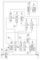
- FIG. 4 is an example in which the image pickup apparatus 1 is divided into a camera body 3 and a lens barrel 2.
- the image pickup device 1 has an image sensor (image sensor) 12, a camera signal processing unit 13, a recording control unit 14, a display unit 15, an output unit 16, an operation unit 17, a power supply unit 18, a camera control unit 30, and a memory in the camera body 3. It has a part 31. Further, the lens barrel 2 has a lens system 21, a lens system drive unit 22, and a lens barrel control unit 23.
- the lens system 21 in the lens barrel 2 includes a lens such as a zoom lens and a focus lens, an aperture mechanism, and the like. Light from the subject (incident light) is guided by the lens system 21 and condensed on the image pickup device 12.
- the image pickup device 12 is configured as, for example, a CCD (Charge Coupled Device) type, a CMOS (Complementary Metal Oxide Semiconductor) type, or the like.
- the image sensor 12 executes, for example, CDS (Correlated Double Sampling) processing, AGC (Automatic Gain Control) processing, and the like on the electric signal obtained by photoelectric conversion of the received light, and further performs A / D (Analog / Digital). Perform conversion processing. Then, the image pickup signal as digital data is output to the camera signal processing unit 13 and the camera control unit 30 in the subsequent stage.
- the camera signal processing unit 13 is configured as an image processing processor by, for example, a DSP (Digital Signal Processor) or the like.
- the camera signal processing unit 13 performs various signal processing on the digital signal (image pickup image signal) from the image pickup element 12. For example, as a camera process, the camera signal processing unit 13 performs preprocessing, simultaneous processing, YC generation processing, resolution conversion processing, codec processing, and the like.
- a clamping process for clamping the black level of R (red), G (green), and B (blue) to a predetermined level with respect to the captured image signal from the image sensor 12, and a clamping process for R, G, and B are performed. Performs correction processing between color channels.
- a color separation processing is performed so that the image data for each pixel has all the color components of R, G, and B. For example, in the case of an image sensor using a Bayer array color filter, demosaic processing is performed as color separation processing.
- YC generation process a luminance (Y) signal and a color (C) signal are generated (separated) from the image data of R, G, and B.
- the resolution conversion process the resolution conversion process is executed for the image data to which various signal processes have been performed.
- the recording control unit 14 records and reproduces, for example, a recording medium using a non-volatile memory.
- the recording control unit 14 performs a process of recording an image file such as moving image data or still image data, a thumbnail image, or the like on a recording medium, for example.
- the actual form of the recording control unit 14 can be considered in various ways.
- the recording control unit 14 may be configured as a flash memory built in the image pickup device 1 and a write / read circuit thereof, or a recording medium that can be attached to and detached from the image pickup device 1, such as a memory card (portable flash memory, etc.). ) May be in the form of a card recording / playback unit that performs recording / playback access. Further, it may be realized as an HDD (Hard Disk Drive) or the like as a form built in the image pickup apparatus 1.
- HDD Hard Disk Drive
- the display unit 15 is a display unit that displays various displays to the imager, and specifically shows the display panel 4 and the viewfinder 5 shown in FIG.
- the display unit 15 causes various displays to be executed on the display screen based on the instructions of the camera control unit 30.
- the display unit 15 displays a reproduced image of image data read from a recording medium by the recording control unit 14.
- the display unit 15 is supplied with image data of the captured image whose resolution has been converted for display by the camera signal processing unit 13.
- the display unit 15 displays a so-called through image (an image pickup monitor image based on the subject light received by the image pickup element 12) by displaying the image based on the image data of the image pickup image in response to the instruction of the camera control unit 30. ..
- the display unit 15 causes various operation menus, icons, messages, etc., that is, display as a GUI (Graphical User Interface) to be executed on the screen based on the instruction of the camera control unit 30.
- GUI Graphic User Interface
- the output unit 16 performs data communication and network communication with an external device by wire or wirelessly.
- the image data (still image file or moving image file) is transmitted and output to an external display device, recording device, playback device, information processing device, or the like.
- the output unit 16 is a network communication unit, it communicates with various networks such as the Internet, a home network, and a LAN (Local Area Network), and transmits / receives various data to / from a server, a terminal, etc. on the network. You may do so.
- the operation unit 17 collectively shows input devices for the user to perform various operation inputs. Specifically, the operation unit 17 shows various operators provided on the camera body 3. That is, the operation unit 17 includes the above-mentioned F value mode key 81, ISO mode key 82, SS mode key 84, set key 83, front dial 72, rear dial 73, wheel 74, and the like.
- the operation unit 17 detects the user's operation, and the signal corresponding to the input operation is sent to the camera control unit 30.
- a touch panel may be used as well as an operator such as a physical key or a dial.
- various operations may be possible by forming a touch panel on the display panel 4 and operating the touch panel using icons, menus, and the like to be displayed on the display panel 4.
- the operation unit 17 may detect a user's tap operation or the like using a touch pad or the like.
- the operation unit 17 may be configured as a reception unit for an operation signal from an external operation device such as a separate remote controller.
- the power supply unit 18 generates a power supply voltage Vcc required for each unit from, for example, a battery loaded inside, and supplies it as an operating voltage.
- the power supply voltage Vcc by the power supply unit 18 is configured to be supplied to the circuit and the motor in the lens barrel 2.
- the power supply unit 18 may be formed with a circuit for charging the battery or a circuit for generating the power supply voltage Vcc using the DC voltage converted and input by the AC adapter connected to the commercial AC power supply as the power supply. ..
- the camera control unit 30 is composed of a microcomputer (arithmetic processing unit) provided with a CPU (Central Processing Unit).
- the memory unit 31 stores information or the like used for processing by the camera control unit 30.
- a ROM Read Only Memory
- RAM Random Access Memory
- flash memory and the like are comprehensively shown.
- the memory unit 31 may be a memory area built in the microcomputer chip as the camera control unit 30, or may be configured by a separate memory chip.
- the camera control unit 30 controls the entire image pickup apparatus 1 and the lens barrel 2 by executing a program stored in the ROM of the memory unit 31, the flash memory, or the like.
- the camera control unit 30 controls the shutter speed and ISO value of the image sensor 12, gives instructions for various signal processing in the camera signal processing unit 13, captures and records according to the user's operation, and reproduces the recorded image file. , User interface operation, etc., control the operation of each necessary part.
- the camera control unit 30 performs, for example, autofocus control for automatically focusing on a target subject, instructions for an aperture mechanism for controlling an F value, and the like.
- the RAM in the memory unit 31 is used as a work area for various data processing of the CPU of the camera control unit 30 to temporarily store data, programs, and the like.
- the ROM and flash memory (nonvolatile memory) in the memory unit 31 include an OS (Operating System) for the CPU to control each unit, content files such as image files, application programs for various operations, and firmware. It is used for memory of etc.
- the camera control unit 30 communicates with the lens barrel control unit 23 and gives various instructions.
- the lens barrel 2 is equipped with, for example, a lens barrel control unit 23 using a microcomputer, and various data communication with the camera control unit 30 is possible.
- the camera control unit 30 gives a drive instruction regarding the zoom lens, focus lens, aperture mechanism, etc. to the lens barrel control unit 23.
- the lens barrel control unit 23 controls the lens system drive unit 22 in response to these drive instructions to execute the operation of the lens system 21.
- wired communication is executed between the camera control unit 30 and the lens barrel control unit 23.
- the camera control unit 30 and the lens barrel control unit 23 may be configured to be able to perform wireless communication.
- the lens system drive unit 22 is provided with, for example, a motor driver for a zoom lens drive motor, a motor driver for a focus lens drive motor, a motor driver for a motor of an aperture mechanism, and the like. These motor drivers apply a drive current to the corresponding driver in response to an instruction from the lens barrel control unit 23 to move the focus lens and the zoom lens, open and close the aperture blades of the aperture mechanism, and the like.
- Mode transition> For example, in the image pickup apparatus 1 having the above configuration, the mode transitions related to exposure will be described below.
- the set values related to exposure include an F value, an SS value, and an ISO value.
- Auto mode and manual mode are prepared as control modes for these.
- the auto mode is, for example, a mode in which the camera control unit 30 automatically optimizes the set value.
- the manual mode is a mode in which the user manually adjusts the set value by using, for example, the above-mentioned front dial 72, rear dial 73, wheel 74, and the like.
- the auto mode and the manual mode can be individually selected for each of the F value, the SS value, and the ISO value, and the exposure can be set by the combination thereof. Further, when the auto mode is switched to the manual mode, the manual mode is started from the value inherited from the value of the auto mode immediately before the switching. As a result, the user can make a rough adjustment in the auto mode and then manually adjust it in the manual mode to drive it to his / her desired state, which is extremely convenient.
- the operation of switching between the auto mode and the manual mode is performed by the operation of the first aspect of the mode controller (individual correspondence keys (81, 82, 84) and set key 83).
- the operation of the first aspect is an operation in which an erroneous operation is less likely to occur as compared with the operation of the second aspect described below.
- the operation of the second aspect is a simple operation, a simple operation, or an operation that the user feels that the operation responsiveness is better than the operation of the first aspect.
- the operation of the first aspect is a long press
- the operation of the second aspect is a short press.
- the short press is a pressing operation for less than a predetermined time, for example, less than 1 second.
- the long press is a continuous pressing operation for a predetermined time or longer, for example, 1 second or longer.
- the user can arbitrarily change the set value by using the setting value changing controls such as the front dial 72, the rear dial 73, and the wheel 74, but the user unintentionally touches these setting value changing controls.
- the set value may be changed.
- the user may not notice that the setting has been changed, and an unintended image may be taken.
- the locked state can be selected in the manual mode.
- the locked state is a state in which the set value is not changed even if the set value change operator is operated. That is, it is assumed that the normal manual mode in which the set value is changed by the operation of the set value change operator is the unlocked state, and the unlocked state and the locked state can be selected in the manual mode.
- providing a separate operator for switching between the locked state and the unlocked state is disadvantageous in terms of the design of the key layout of the camera body 3, and the operability deteriorates due to the excessive number of keys. Switching between locked and unlocked states is troublesome. Therefore, in the present embodiment, the mode controller can also be used for the operation of switching between the locked state and the unlocked state. That is, the locked state and the unlocked state are switched by the operation of the second aspect of the mode controller (individual corresponding key (81, 82, 84) or set key 83).
- the locked state in the manual mode can be set by using the mode operator as it is. This can be expected to have the effect of preventing an erroneous operation in which the user unintentionally touches the setting value changing operator such as the front dial 72 in the manual mode and the setting value is changed without knowing it.
- FIG. 5 shows a state transition according to an operation of a mode operator or the like.
- the operation u1 when in the auto mode, shifts to the manual mode.
- the operation u2 when in the manual mode, shifts to the auto mode.
- the state In the manual mode, the state is not locked at the beginning of the transition, but the state is changed to the locked state (manual locked state) by the operation u4 (short press).
- the operation u5 When in the locked state, the operation u5 (short press) returns to the unlocked state. If the operation u6 (hold down) is performed while in the locked state, the mode shifts to the auto mode.
- the operation u3 (setting value changing operation) by the front dial 72, the rear dial 73, and the wheel 74, which are the setting value changing operators, is effective.
- the operation by the front dial 72, the rear dial 73, and the wheel 74, which are the setting value change operators, is not accepted as invalid. That is, the setting value cannot be changed.
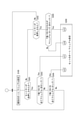
- FIG. 6 A processing example relating to mode switching of the camera control unit 30 as the first embodiment will be described with reference to FIG.
- This first embodiment assumes a case where an F value mode key 81, an ISO mode key 82, and an SS mode key 84 are provided as individual corresponding keys as mode controls.
- the individual corresponding key shown in FIG. 6 refers to any one of the F value mode key 81, the ISO mode key 82, and the SS mode key 84.
- the individual corresponding key is the F value mode key 81, and when the wheel 74 is assigned to the F value change operation, the setting is made.
- the value change controller is the wheel 74. Further, when the explanation of FIG.
- FIG. 6 is considered as the explanation regarding the mode of the SS value, the individual corresponding key is the SS mode key 84, and when the front dial 72 is assigned to the operation of changing the SS value, The set value change operator is the front dial 72.
- the same idea applies to the ISO value.
- FIG. 6 shows only the process for the state transition shown in FIG. 5, and does not touch on the process related to the actual exposure control such as the automatic change of the set value in the auto mode and the instruction corresponding to it (the process). The same applies to FIGS. 7, 8 and 9 described later).
- the camera control unit 30 selects the manual mode as the initial state when the power is turned on. Then, the camera control unit 30 has a period from when the operation related to mode switching or setting value change as the exposure setting is started (or after it becomes possible) until the setting change is completed, in step S101 of FIG. To step S102. For example, when the image pickup apparatus 1 transitions to a reproduction mode in which the operation related to the exposure setting cannot be performed, or when a certain time has elapsed since the last operation related to the exposure is performed, it is determined that the setting change is completed.
- step S102 the camera control unit 30 maintains the unlocked state of the manual mode.
- the camera control unit 30 monitors the long press operation of the individual corresponding key (one of the F value mode key 81, the ISO mode key 82, and the SS mode key 84) in step S103, and steps S104.
- Monitors the short-press operation of the individual corresponding key and monitors the operation of the set value change controller (any of the front dial 72, the rear dial 73, and the wheel 74) in step S105.
- step S105 When the operation of the set value change controller is detected in step S105, the camera control unit 30 proceeds to step S140 and changes the set value (either F value, SS value, or ISO value) according to the operation.
- set value either F value, SS value, or ISO value
- step S103 When the long press operation of the individual corresponding key is detected in step S103, the camera control unit 30 proceeds to step S120 and switches to the auto mode.
- the camera control unit 30 monitors the long press operation of the individual corresponding key in the step S121 while maintaining the auto mode in the step S120 until the setting change is determined to be completed in the step S122. do.
- step S121 When the long press operation of the individual corresponding key is detected in step S121, the camera control unit 30 proceeds to step S130 so that the initial value of the set value in the manual mode inherits the set value of the auto mode at that time. .. Then, in step S102, the mode is changed to the manual mode. For example, if the long press of the F value mode key 81 is detected, in step S130, the F value set in the auto mode process immediately before this operation is maintained, and in step S102, the mode is changed to the manual mode. Therefore, in the manual mode, the user can perform a change operation such as increasing or decreasing the F value starting from the F value in the immediately preceding auto mode.
- step S110 When the short press operation of the individual corresponding key is detected in step S104 in the manual mode, the camera control unit 30 proceeds to step S110 to switch to the locked state of the manual mode. For example, when a short press of the F value mode key 81 is detected, the F value is set to an immutable locked state. In the locked state, the camera control unit 30 monitors the long press operation of the individual corresponding key in step S112 while maintaining the locked state in step S110 until it is determined in step S111 that the setting change is completed. Also, in step S113, the short press operation of the individual corresponding key is monitored.
- step S112 the camera control unit 30 proceeds to step S120 and switches to the auto mode for the set value corresponding to the individual corresponding key.
- step S113 the camera control unit 30 proceeds to step S102, releases the lock state for the set value corresponding to the individual corresponding key, and sets the set value by the set value change operator. Allows changes.
- the camera control unit 30 applies the F value, the ISO value, and the SS value to the auto mode, respectively.
- the manual mode can be switched and the locked state and the unlocked state can be switched, and the possibility that the set value is changed due to an erroneous operation can be reduced.
- the camera control unit 30 selects the manual mode as the initial state when the power is turned on. Then, the camera control unit 30 proceeds from step S201 to step S202 in FIG. 7 until it is determined that the setting change for exposure is completed. In step S202, the camera control unit 30 maintains the unlocked state of the manual mode for all of the F value, the ISO value, and the SS value.
- the camera control unit 30 monitors the long press operation of the set key 83 in step S203, monitors the short press operation of the set key 83 in step S204, and the set value change controller in step S205. Monitor the operation (all of the front dial 72, the rear dial 73, and the wheel 74).
- step S205 the camera control unit 30 proceeds to step S240 and changes the set value (either F value, SS value, or ISO value) according to the operation. For example, if the wheel 74 is operated, the F value is changed. If the front dial 72 is operated, the SS value is changed. If the rear dial 73 is operated, the ISO value is changed.
- the set value either F value, SS value, or ISO value
- step S203 When the long press operation of the set key 83 is detected in step S203, the camera control unit 30 proceeds to step S220 and switches all the F value, ISO value, and SS value to the auto mode.
- the camera control unit 30 monitors the long press operation of the set key 83 in step S221 while maintaining the auto mode in step S220 until it is determined in step S222 that the setting change is completed. do.
- step S221 When the long press operation of the set key 83 is detected in step S221, the camera control unit 30 proceeds to step S230, and the initial value of the set value in the manual mode is the set value (F value, F value,) of the auto mode at that time. SS value, ISO value) will be inherited. Then, in step S202, the mode is changed to the manual mode.
- step S210 When the short press operation of the set key 83 is detected in step S204 in the manual mode, the camera control unit 30 proceeds to step S210 and switches all of the F value, the ISO value, and the SS value to the locked state of the manual mode. In the locked state, the camera control unit 30 maintains the locked state of the F value, ISO value, and SS value in step S210 until it is determined in step S211 that the setting change is completed, and the set key in step S212.
- the long press operation of 83 is monitored, and the short press operation of the set key 83 is monitored in step S213.
- step S212 the camera control unit 30 proceeds to step S220 and switches all the F value, ISO value, and SS value to the auto mode.
- step S213 the camera control unit 30 proceeds to step S202, releases the locked state for all the F value, ISO value, and SS value, and sets the set value by the set value change operator. Can be changed.
- the camera control unit 30 By performing the above processing of FIG. 7 by the camera control unit 30, it is possible to collectively switch the mode and switch between the locked state and the unlocked state for the F value, the ISO value, and the SS value. This can be expected to improve user operability.
- FIG. 8 shows an example of processing from the state after the operation of the individual corresponding key. That is, the individual auto / manual setting in step S100 shows the whole of FIG.
- the camera control unit 30 monitors steps S301 and S302 in FIG. 8 in a state where the processing according to the operation of the individual corresponding key is being performed in the processing of FIG.
- step S301 the camera control unit 30 monitors whether or not the set key 83 has been briefly pressed.
- step S302 the camera control unit 30 monitors whether or not the set key 83 has been pressed and held.
- step S301 the camera control unit 30 determines in step S303 whether or not the F value, ISO value, and SS value are all in the unlocked state in the manual mode at that time. do. If all are in the unlocked state in the manual mode, the process proceeds to step S210 in FIG. 7, and all the F value, ISO value, and SS value are locked, as shown as “ct1” in the auto / manual setting of the set in step S200. And. Note that step S200 indicates the entire process of FIG.
- step S303 If the F value, ISO value, and SS value are all not in the unlocked state in the manual mode in step S303, the camera control unit 30 is in step S304, and all the F value, ISO value, and SS value are manual. Determines whether or not the mode is locked. If this is the case, the process proceeds to step S202 in FIG. 7 as shown as “ct2”, and all the F value, ISO value, and SS value are set to the unlocked state.
- step S302 When the long press operation of the set key 83 is detected in step S302, the camera control unit 30 is in step S305, and at that time, one of the F value, the ISO value, and the SS value is in the manual mode (unlocked state or locked state). Determine if it exists. If any of them is in the manual mode, the process proceeds to step S220 in FIG. 7 as shown as “ct3”, and all the F value, ISO value, and SS value are locked.
- step S305 when any one of the F value, the ISO value, and the SS value does not correspond to the condition of the manual mode, that is, in the case of all the auto modes, the camera control unit 30 is shown as "ct4" in the step of FIG. Proceed to S230, take over the F value, ISO value, and SS value at that time, and transition to the manual mode.
- FIG. 9 shows an example of processing from the state after the operation of the set key 83. That is, it is a process from the case where the auto / manual setting process of the set in step S200 is performed.
- the camera control unit 30 monitors steps S351 and S352 in FIG. In step S351, the camera control unit 30 monitors whether or not the individual corresponding key has been briefly pressed. In step S352, the camera control unit 30 monitors whether or not the individual corresponding key has been pressed and held.
- step S354 the camera control unit 30 determines in step S354 whether or not the F value, the ISO value, and the SS value are all locked in the manual mode. If all are in the locked state in the manual mode, the process proceeds to step S102 in FIG. 6 as shown as “ct7” in step S100, and any of the set values (F value, ISO value, SS value) corresponding to the operated individual corresponding key. Or) is in the unlocked state.
- step S354 If all of the F value, ISO value, and SS value are in the unlocked state in the manual mode in step S354, the camera control unit 30 proceeds to step S110 in FIG. 6 as shown as “ct8” in step 100.
- the set value (any of the F value, ISO value, and SS value) corresponding to the operated individual correspondence key is set to the locked state.
- step S353 the camera control unit 30 determines in step S353 whether or not the F value, the ISO value, and the SS value are all in the auto mode. If all are in the auto mode, the process proceeds to step S130 in FIG. 6 as shown as “ct5” in step S100, and the set value (either F value, ISO value, or SS value) corresponding to the operated individual corresponding key is set. , Takes over the value in auto mode and sets it to manual mode.
- step S353 If it is determined in step S353 that all of the F value, ISO value, and SS value are not in the auto mode, that is, all are in the manual mode, the camera control unit 30 indicates step S120 in FIG. 6 as “ct6” in step 100.
- the auto mode is set to the set value (any of the F value, ISO value, and SS value) corresponding to the operated individual corresponding key.
- FIG. 10 is an example of displaying various icons on the display panel 4, for example.
- the camera control unit 30 displays the SS value display 50, the F value display 51, the ISO value display 52, and the dial guides 53, 54, 55 on the display panel 4 as numerical display or icon related to the set value or mode related to exposure. These may be displayed in the viewfinder 5.
- the SS value display 50 indicates the current SS value, for example, "1/250".
- the F value display 51 indicates the current F value, for example, "F5.6”.
- the ISO value display 52 indicates the current ISO value. In the figure, it is shown that the ISO sensitivity is auto as “ISO AUTO", but a numerical value may be shown as "ISO 200".
- the dial guides 53, 54, 55 indicate which set value is assigned to which dial (or wheel).
- the dial guide 53 indicates the front dial 72, and in the figure, the letters “Av” are superimposed to indicate that the front dial 72 is assigned to the operation of the F value.
- the dial guide 54 indicates the rear dial 73, and in the figure, the characters “ISO” are superimposed to indicate that the rear dial 73 is assigned to the operation of the ISO value.
- the dial guide 55 indicates the wheel 74, and in the figure, the letters “Tv” are superimposed to indicate that the wheel 74 is assigned to operate the SS value.
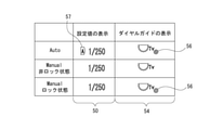
- FIG. 11 shows a display example in which the SS value is taken as an example and is changed according to the mode transition and the locked state and the unlocked state. Note that, unlike the example of FIG. 10, FIG. 11 shows a state in which the operation of the SS value is assigned to the rear dial 73. That is, the dial guide 54 displays the SS value setting value change operator.
- the operations u1, u2, u3, u4, u5 in FIG. 11 have the same meaning as in FIG.
- the auto mark 57 including the character "A” is added to the SS value display 50 to indicate that the mode is the auto mode.
- the character "Tv” is added to the dial guide 54 indicating the rear dial 73, indicating that the rear dial 73 is an operator of the SS value.
- the prohibition mark 56 indicates that the operation of the rear dial 73 is invalid.
- the auto mark 57 is erased, indicating that the mode is manual mode.
- the prohibition mark 56 is erased in the dial guide 54, indicating that the rear dial 73 can be used to operate the SS value.
- the display color of the SS value display 50 may be changed to clearly indicate that the operation is in progress.
- the prohibition mark 56 is displayed on the dial guide, indicating that the operation of the rear dial 73 is invalidated.
- FIG. 12 shows the changes in the set value (SS value display 50) and the display of the dial guide 54 in each of the above states.
- the presence or absence of the auto mark 57 indicates the distinction between the auto mode and the manual mode.
- the dial guide 54 is indicated by the prohibition mark 56 that the operation is disabled when the auto mode and the manual mode are locked.
- the above shows the SS value display 50, but it is the same that the auto mark 57 is added to the F value display 51 and the ISO value display 52 in the auto mode. Further, the dial guides 53 and 55 are also indicated by the prohibition mark 56 that the operation is disabled in the auto mode and in the manual mode lock.
- the above display example is an example.
- Various display examples such as characters and icons indicating the auto mode and the manual mode can be considered.
- the display example of the allocation and the display indicating the inoperable state are not limited to the prohibition mark 56, and other examples can be considered.
- an icon or a character indicating the locked state may be displayed instead of the prohibition mark 56.
- the image pickup apparatus 1 of the embodiment is a mode controller (81, 82, 83, 84) that switches between a manual mode in which a set value related to image pickup is changed according to an operation and an auto mode in which the set value related to image pickup is automatically adjusted. ). Further, in response to detecting the operation of the first mode of the mode operator (for example, long press), the process of switching between the manual mode and the auto mode is performed, and the operation of the second mode of the mode operator (for example, short) is performed in the manual mode.
- the first mode of the mode operator for example, long press
- a camera control unit 30 performs a process of switching between a non-locked state that enables a set value change operation and a locked state that disables a set value change operation in response to detecting a push). If the mode controller (81, 82, 83, 84) switches between auto mode and manual mode by a simple pressing operation, the mode will be switched even if the user unintentionally touches it. Sometimes. On the other hand, the camera control unit 30 determines a plurality of operation modes for the mode controller and switches the mode at the time of the operation of the specific first mode, so that the mode can be switched by an operation not intended by the user. Is prevented from occurring. This prevents the set value from being changed unintentionally and improves usability.
- the mode operator is an operator capable of pressing
- the operation of the first aspect is a long pressing operation which is continuous pressing for a predetermined time or longer
- the operation of the second aspect is less than the predetermined time.
- An example of a short-press operation which is the pressing of the button, is given.
- Mode switching is performed by long-pressing the mode controller (81, 82, 83, 84), but it is expected that long-pressing is a more conscious operation than short-pressing. Also, if you touch it unconsciously, do not press and hold it. Therefore, by making the long press an operation for mode switching, it is effective in preventing unintended mode switching.
- examples other than long press and short press can be considered for the operation of the first aspect and the operation of the second aspect. It is desirable that the operation of the first aspect is an operation that is less likely to cause an erroneous operation than the operation of the second aspect, and as described above, the operation of the second aspect is a simpler operation or simpler than the operation of the first aspect. The operation or the operation that the user feels that the operation responsiveness is good.
- the operation of the second aspect is a single push
- the operation of the first mode is a double push
- -The operation of the second aspect is a single click
- the operation of the first aspect is a double click.
- the operation of the second aspect is a pressing operation
- the operation of the first aspect is a pulling operation
- -The operation of the second aspect is a pressing operation
- the operation of the first aspect is a sliding operation.
- the setting value is a plurality of setting values related to exposure, and a plurality of individual corresponding controls (“individual corresponding key” corresponding to each of the plurality of setting values individually as a mode operator.
- the F-number mode key 81, the ISO mode key 82, and the SS mode key 84) are prepared.
- the camera control unit 30 switches between the auto mode and the manual mode for the corresponding set value according to the operation of the first aspect of the individual corresponding operator, and corresponds to the operation of the second aspect of the individual corresponding operator. Switch between unlocked and locked states for the corresponding set value. That is, as described with reference to FIG.
- the F value, the ISO value, and the SS value are set according to the operation of the F value mode key 81, the ISO mode key 82, and the SS mode key 84 as the individual corresponding keys. Either the auto mode and the manual mode are switched, and the unlocked state and the locked state are switched in the manual mode. This makes it possible to prevent unintended mode changes for each set value individually and to lock each set value individually for unintended changes, which further helps prevent erroneous operation by the user and improve operability. It becomes valid.
- the set values are a plurality of set values related to exposure, and as a mode controller, a set key 83 corresponding to the plurality of set values is prepared collectively, and the camera control unit 30 is used. , Performs batch switching between auto mode and manual mode for a plurality of setting values according to the operation of the first aspect of the set key 83, and for the plurality of setting values according to the operation of the second aspect of the set key 83. Performs batch switching between unlocked and locked states. That is, as described with reference to FIG. 7, according to the operation of the set key 83, the F value, ISO value, and SS value are collectively switched between the auto mode and the manual mode, and the unlocked state in the manual mode. The locked state is switched.
- a plurality of individually supported controls corresponding to each of the plurality of set values individually, and a plurality of set values collectively.
- the corresponding set key 83 may be provided.
- the camera control unit 30 switches between the auto mode and the manual mode for the corresponding set value according to the operation of the first aspect of the individual corresponding operator. Further, the unlocked state and the locked state of the corresponding set value are switched according to the operation of the second aspect of the individual corresponding operator. Further, the camera control unit 30 sets all of the plurality of set values to the auto mode according to the operation of the first aspect of the set key 83 when a part or all of the plurality of set values is in the manual mode.
- the camera control unit 30 sets the manual mode in the initial state.
- the front dial 72, the rear dial 73, the wheel 74, etc. are not disabled from the beginning. Since the user is consciously performing the auto mode, the user can be aware of the state in which the front dial 72 or the like is invalid.
- the camera control unit 30 assumes that the set value at the time of transition from the auto mode to the manual mode is the value in the immediately preceding auto mode. In other words, the transition to the manual mode is made so that the set value automatically adjusted in the auto mode is inherited. This enables the user to make fine adjustments in the manual mode from the state automatically adjusted in the auto mode to the optimum state. However, in this case, if the auto mode and the manual mode are switched by an erroneous operation, the setting value driven by the operation of the manual mode will be changed by the automatic adjustment of the auto mode, and will be changed when the user returns to the manual mode. It will be in the state of performing manual operation from the set value of the auto mode.
- setting the mode to be switched by pressing and holding the button to prevent erroneous operation of the mode change from occurring does not waste the state in which the set value is finely adjusted. In that respect, it is very effective.
- the set value is a plurality of set values related to exposure, and in the manual mode, each has a plurality of set value change operators assigned to correspond to a certain set value
- the camera control unit 30 Gives an example of controlling to execute the display of the dial guides 53, 54, 55 indicating the setting value change operator corresponding to each setting value. This makes it easier for the user to understand which of the F value, SS value, and ISO value the set value change controller of the front dial 72, rear dial 73, wheel 74, etc. corresponds to, and the operability is improved. Wheel.
- the user may customize which of the F value, the SS value, and the ISO value each of the front dial 72, the rear dial 73, and the wheel 74 is assigned.
- the F value, SS value, and ISO value setting value change operators are assigned to, respectively. Therefore, by displaying the correspondence between the set value and the set value change operator clearly as shown in the dial guide of FIG. 12, it becomes clear what kind of allocation setting the user has made, and the user can use it. It is also possible to prevent confusion in operation.
- the camera control unit 30 has a set value change operator that changes the set value in the manual mode, and the operation of the set value change operator becomes invalid in the auto mode and the locked state.
- a guide display indicating that the display is present for example, an example of controlling the display of the prohibition mark 56 is given. This makes it easier for the user to recognize that the set value changing operation elements such as the front dial 72, the rear dial 73, and the wheel 74 are invalid (the operation is locked), and it is possible to prevent the user from being confused by the operation.
- the image pickup apparatus 1 of the embodiment has a plurality of custom keys C1, C2, C3, and C4 whose operation functions can be changed, and a plurality of individually supported controls can be assigned to different custom keys. I said that.
- the user can arbitrarily assign the F value mode key 81, the ISO mode key 82, and the SS mode key 84 by using the custom keys C1, C2, C3, and C4, and realizes the user's own favorite usability. can.
- the image pickup apparatus 1 of the embodiment has a plurality of custom keys C1, C2, C3, and C4 whose operation functions can be changed, and the set key 83 can be assigned to any of the plurality of custom keys. I said that.
- the user can arbitrarily assign the set key 83 by using the custom keys C1, C2, C3, and C4, and can realize the user's own favorite usability.
- the F value mode key 81, the ISO mode key 82, the SS mode key 84, and the set key 83 can be assigned to the custom keys C1, C2, C3, and C4 separately. Achieves suitable usability.
- examples of the set values as an F value, a shutter speed value, and an ISO value are given.
- an example of switching the mode related to exposure and switching between the locked state and the unlocked state of the set value is given as the mode switching, but the technique of the present disclosure can be applied to other mode switching and the like. For example, it can be applied to switching the mode related to the focus operation and the locked state of the set value, switching the mode related to the zoom operation and the locked state of the set value, switching the shooting mode, and switching the locked state of the set value.
- the program of the embodiment detects the operation of switching between the manual mode and the auto mode according to the detection of the operation of the first aspect of the mode controller, and the operation of the second aspect of the mode controller in the manual mode.
- the process of switching between the unlocked state that enables the setting value change operation in the manual mode and the locked state that disables the setting value change operation in the manual mode is performed, for example, a CPU, a DSP, or a device including these.
- the image pickup apparatus 1 of the embodiment it is suitable for a wide range of provision of the image pickup apparatus 1 of the embodiment.
- a mobile terminal device such as a smartphone or tablet, a mobile phone, a personal computer, a game device, a video device, a PDA (Personal Digital Assistant), etc., which has an imaging function.
- a smartphone or the like can function as the image pickup apparatus 1 of the present disclosure.
- the present technology can also adopt the following configurations.
- a mode controller that switches between a manual mode that changes the setting values related to imaging according to the operation and an auto mode that automatically adjusts the setting values related to imaging.
- the process of switching between the manual mode and the auto mode is performed, and the operation of the second aspect of the mode operator is detected during the manual mode.
- An image pickup device including a control unit that performs a process of switching between a non-locked state that enables a set value change operation in the manual mode and a locked state that disables the set value change operation in the manual mode.
- the mode operator is an operator that can be pressed and operated.
- the operation of the first aspect is a long press operation which is a continuous pressing for a predetermined time or longer.
- the image pickup apparatus according to (1) above, wherein the operation of the second aspect is a short-press operation in which the pressing is performed for less than a predetermined time.
- the set values are a plurality of set values related to exposure, and are set values.
- As the mode controls a plurality of individually supported controls, each of which individually corresponds to a plurality of set values, are prepared.
- the control unit Switching between the auto mode and the manual mode for the corresponding set value according to the operation of the first aspect of the individual corresponding operator is executed.
- the image pickup apparatus which switches between the unlocked state and the locked state for the set value corresponding to the operation of the second aspect of the individual corresponding operator.
- the set values are a plurality of set values related to exposure, and are set values.
- As the mode operator a set operator corresponding to a plurality of set values is prepared at once.
- the control unit In accordance with the operation of the first aspect of the set operator, the automatic mode and the manual mode are collectively switched between the plurality of set values.
- the set values are a plurality of set values related to exposure, and are set values.
- As the mode controls a plurality of individually corresponding controls for each of the plurality of set values and a set operator corresponding to the plurality of set values collectively are prepared.
- the control unit Switching between the auto mode and the manual mode for the corresponding set value according to the operation of the first aspect of the individual corresponding operator is executed. Switching between the unlocked state and the locked state for the corresponding set value according to the operation of the second aspect of the individual corresponding operator is executed. In response to the operation of the first aspect of the set operator when a part or all of the plurality of set values are in the manual mode, switching is executed so that all the plurality of set values are in the auto mode.
- the above-mentioned batch switching between the unlocked state and the locked state of the plurality of set values is executed according to the operation of the second aspect of the set operator when all of the plurality of set values are in the manual mode.
- the imaging device according to any one of (1) to (4).
- the image pickup apparatus according to any one of (1) to (5) above, wherein the control unit sets the manual mode in the initial state.
- the control unit The image pickup apparatus according to any one of (1) to (5) above, wherein the set value at the time of transition from the auto mode to the manual mode is the value in the immediately preceding auto mode.
- the set values are a plurality of set values related to exposure, and are set values.
- each has a plurality of set value change operators assigned to correspond to a certain set value.
- the image pickup apparatus according to any one of (1) to (7) above, wherein the control unit controls to execute a guide display indicating the set value change operator corresponding to each set value. (9) It has a set value change operator that changes the set value in the manual mode. The control unit controls to execute a guide display indicating that the operation of the set value change controller is invalid in the auto mode and the locked state (1) to (8).
- the imaging device according to any one. (10) It has multiple custom controls that can change the settings of operation functions.
- the image pickup apparatus according to (3) or (5) above, wherein a plurality of the individually supported controls can be assigned to different custom controls.
- the image pickup apparatus has multiple custom controls that can change the settings of operation functions.
- the image pickup apparatus according to (4) or (5) above, wherein the set operator can be assigned to any of the plurality of custom operators.
- the image pickup apparatus according to any one of (1) to (11) above, wherein the set value is an F value.
- the image pickup apparatus according to any one of (1) to (12) above, wherein the set value is a shutter speed value.
- the image pickup apparatus is an ISO value.
- a process of switching between the manual mode and the auto mode in response to detecting the operation of the first aspect of the mode operator.
- the unlocked state that enables the setting value changing operation in the manual mode and the setting value changing operation in the manual mode are disabled. The process of switching between the locked state and A program to execute.
Landscapes
- Physics & Mathematics (AREA)
- General Physics & Mathematics (AREA)
- Engineering & Computer Science (AREA)
- Multimedia (AREA)
- Signal Processing (AREA)
- Studio Devices (AREA)
Priority Applications (1)
| Application Number | Priority Date | Filing Date | Title |
|---|---|---|---|
| JP2022540205A JP7697470B2 (ja) | 2020-07-30 | 2021-07-19 | 撮像装置、制御方法、プログラム |
Applications Claiming Priority (2)
| Application Number | Priority Date | Filing Date | Title |
|---|---|---|---|
| JP2020-129326 | 2020-07-30 | ||
| JP2020129326 | 2020-07-30 |
Publications (1)
| Publication Number | Publication Date |
|---|---|
| WO2022024849A1 true WO2022024849A1 (ja) | 2022-02-03 |
Family
ID=80035557
Family Applications (1)
| Application Number | Title | Priority Date | Filing Date |
|---|---|---|---|
| PCT/JP2021/027014 Ceased WO2022024849A1 (ja) | 2020-07-30 | 2021-07-19 | 撮像装置、制御方法、プログラム |
Country Status (2)
| Country | Link |
|---|---|
| JP (1) | JP7697470B2 (https=) |
| WO (1) | WO2022024849A1 (https=) |
Citations (5)
| Publication number | Priority date | Publication date | Assignee | Title |
|---|---|---|---|---|
| JP2006191235A (ja) * | 2005-01-04 | 2006-07-20 | Sony Corp | 撮像装置およびその制御方法 |
| JP2012235393A (ja) * | 2011-05-06 | 2012-11-29 | Nikon Corp | 制御装置、撮像システムおよびプログラム |
| JP2013247508A (ja) * | 2012-05-25 | 2013-12-09 | Canon Inc | 自動追尾カメラの制御装置及び該制御装置を有する自動追尾カメラ |
| WO2017217082A1 (ja) * | 2016-06-14 | 2017-12-21 | 富士フイルム株式会社 | 設定装置、設定方法、設定プログラム及びカメラ |
| JP2019204076A (ja) * | 2018-05-17 | 2019-11-28 | パナソニックIpマネジメント株式会社 | 撮像装置 |
Family Cites Families (1)
| Publication number | Priority date | Publication date | Assignee | Title |
|---|---|---|---|---|
| JP2018191235A (ja) | 2017-05-11 | 2018-11-29 | コニカミノルタ株式会社 | 画像形成装置 |
-
2021
- 2021-07-19 JP JP2022540205A patent/JP7697470B2/ja active Active
- 2021-07-19 WO PCT/JP2021/027014 patent/WO2022024849A1/ja not_active Ceased
Patent Citations (5)
| Publication number | Priority date | Publication date | Assignee | Title |
|---|---|---|---|---|
| JP2006191235A (ja) * | 2005-01-04 | 2006-07-20 | Sony Corp | 撮像装置およびその制御方法 |
| JP2012235393A (ja) * | 2011-05-06 | 2012-11-29 | Nikon Corp | 制御装置、撮像システムおよびプログラム |
| JP2013247508A (ja) * | 2012-05-25 | 2013-12-09 | Canon Inc | 自動追尾カメラの制御装置及び該制御装置を有する自動追尾カメラ |
| WO2017217082A1 (ja) * | 2016-06-14 | 2017-12-21 | 富士フイルム株式会社 | 設定装置、設定方法、設定プログラム及びカメラ |
| JP2019204076A (ja) * | 2018-05-17 | 2019-11-28 | パナソニックIpマネジメント株式会社 | 撮像装置 |
Also Published As
| Publication number | Publication date |
|---|---|
| JPWO2022024849A1 (https=) | 2022-02-03 |
| JP7697470B2 (ja) | 2025-06-24 |
Similar Documents
| Publication | Publication Date | Title |
|---|---|---|
| CN100591097C (zh) | 带有显示设备的图像拾取设备以及用于显示设备的显示控制方法 | |
| EP1826609B1 (en) | Image pickup apparatus having a help function, and method and program for controlling the same | |
| US7936396B2 (en) | Image-pickup apparatus | |
| US20090051665A1 (en) | Method of providing menu using touchscreen and multimedia apparatus applying the same | |
| US20220264005A1 (en) | Imaging apparatus, imaging method, and program | |
| JP7754091B2 (ja) | 撮像装置、撮像制御装置、撮像装置の制御方法、プログラム | |
| JP7527112B2 (ja) | 電子機器及びその制御方法 | |
| US20160316139A1 (en) | Imaging apparatus, and imaging system | |
| JP7697470B2 (ja) | 撮像装置、制御方法、プログラム | |
| JP4529094B2 (ja) | 撮像装置、機能制御方法および機能制御プログラム | |
| US20250168510A1 (en) | Imaging device and zoom control method | |
| JP2002281373A (ja) | 電子カメラ | |
| JP5602524B2 (ja) | 撮像装置、撮像装置の制御方法及びプログラム並びに記録媒体 | |
| JP7852516B2 (ja) | 撮像装置、撮像制御方法、プログラム | |
| JP2010183244A (ja) | 撮像装置及び撮像装置の制御方法 | |
| JP2005221771A (ja) | 撮像装置及び機能表示方法 | |
| JP2020150501A (ja) | 画像出力装置、画像表示装置、およびそれらの方法 | |
| US11477376B2 (en) | Image capturing apparatus, control method thereof, and recording medium storing program | |
| JP7841531B2 (ja) | 撮像装置、フォーカス制御方法、プログラム | |
| JP7781612B2 (ja) | 表示制御装置及びその制御方法、プログラム、記録媒体 | |
| JP2020167457A (ja) | 画像処理装置、画像処理方法、およびプログラム | |
| JP2003255427A (ja) | カメラ | |
| JP2019168940A (ja) | 電子機器及びその制御方法 | |
| JP2003224763A (ja) | デジタルカメラ | |
| JP2024157961A (ja) | 情報処理装置及びその制御方法及びプログラム |
Legal Events
| Date | Code | Title | Description |
|---|---|---|---|
| 121 | Ep: the epo has been informed by wipo that ep was designated in this application |
Ref document number: 21851093 Country of ref document: EP Kind code of ref document: A1 |
|
| ENP | Entry into the national phase |
Ref document number: 2022540205 Country of ref document: JP Kind code of ref document: A |
|
| NENP | Non-entry into the national phase |
Ref country code: DE |
|
| 122 | Ep: pct application non-entry in european phase |
Ref document number: 21851093 Country of ref document: EP Kind code of ref document: A1 |