WO2022024612A1 - 撮像制御装置、撮像制御装置の作動方法、プログラム、並びに撮像装置 - Google Patents
撮像制御装置、撮像制御装置の作動方法、プログラム、並びに撮像装置 Download PDFInfo
- Publication number
- WO2022024612A1 WO2022024612A1 PCT/JP2021/023987 JP2021023987W WO2022024612A1 WO 2022024612 A1 WO2022024612 A1 WO 2022024612A1 JP 2021023987 W JP2021023987 W JP 2021023987W WO 2022024612 A1 WO2022024612 A1 WO 2022024612A1
- Authority
- WO
- WIPO (PCT)
- Prior art keywords
- image
- filter
- control device
- difference
- unit
- Prior art date
- Legal status (The legal status is an assumption and is not a legal conclusion. Google has not performed a legal analysis and makes no representation as to the accuracy of the status listed.)
- Ceased
Links
Images








Classifications
-
- H—ELECTRICITY
- H04—ELECTRIC COMMUNICATION TECHNIQUE
- H04N—PICTORIAL COMMUNICATION, e.g. TELEVISION
- H04N23/00—Cameras or camera modules comprising electronic image sensors; Control thereof
- H04N23/10—Cameras or camera modules comprising electronic image sensors; Control thereof for generating image signals from different wavelengths
- H04N23/11—Cameras or camera modules comprising electronic image sensors; Control thereof for generating image signals from different wavelengths for generating image signals from visible and infrared light wavelengths
-
- G—PHYSICS
- G03—PHOTOGRAPHY; CINEMATOGRAPHY; ANALOGOUS TECHNIQUES USING WAVES OTHER THAN OPTICAL WAVES; ELECTROGRAPHY; HOLOGRAPHY
- G03B—APPARATUS OR ARRANGEMENTS FOR TAKING PHOTOGRAPHS OR FOR PROJECTING OR VIEWING THEM; APPARATUS OR ARRANGEMENTS EMPLOYING ANALOGOUS TECHNIQUES USING WAVES OTHER THAN OPTICAL WAVES; ACCESSORIES THEREFOR
- G03B11/00—Filters or other obturators specially adapted for photographic purposes
-
- G—PHYSICS
- G03—PHOTOGRAPHY; CINEMATOGRAPHY; ANALOGOUS TECHNIQUES USING WAVES OTHER THAN OPTICAL WAVES; ELECTROGRAPHY; HOLOGRAPHY
- G03B—APPARATUS OR ARRANGEMENTS FOR TAKING PHOTOGRAPHS OR FOR PROJECTING OR VIEWING THEM; APPARATUS OR ARRANGEMENTS EMPLOYING ANALOGOUS TECHNIQUES USING WAVES OTHER THAN OPTICAL WAVES; ACCESSORIES THEREFOR
- G03B15/00—Special procedures for taking photographs; Apparatus therefor
-
- G—PHYSICS
- G06—COMPUTING OR CALCULATING; COUNTING
- G06T—IMAGE DATA PROCESSING OR GENERATION, IN GENERAL
- G06T5/00—Image enhancement or restoration
- G06T5/50—Image enhancement or restoration using two or more images, e.g. averaging or subtraction
-
- G—PHYSICS
- G06—COMPUTING OR CALCULATING; COUNTING
- G06V—IMAGE OR VIDEO RECOGNITION OR UNDERSTANDING
- G06V10/00—Arrangements for image or video recognition or understanding
- G06V10/40—Extraction of image or video features
- G06V10/60—Extraction of image or video features relating to illumination properties, e.g. using a reflectance or lighting model
-
- G—PHYSICS
- G06—COMPUTING OR CALCULATING; COUNTING
- G06V—IMAGE OR VIDEO RECOGNITION OR UNDERSTANDING
- G06V10/00—Arrangements for image or video recognition or understanding
- G06V10/70—Arrangements for image or video recognition or understanding using pattern recognition or machine learning
- G06V10/74—Image or video pattern matching; Proximity measures in feature spaces
- G06V10/761—Proximity, similarity or dissimilarity measures
-
- H—ELECTRICITY
- H04—ELECTRIC COMMUNICATION TECHNIQUE
- H04N—PICTORIAL COMMUNICATION, e.g. TELEVISION
- H04N23/00—Cameras or camera modules comprising electronic image sensors; Control thereof
- H04N23/10—Cameras or camera modules comprising electronic image sensors; Control thereof for generating image signals from different wavelengths
- H04N23/12—Cameras or camera modules comprising electronic image sensors; Control thereof for generating image signals from different wavelengths with one sensor only
-
- H—ELECTRICITY
- H04—ELECTRIC COMMUNICATION TECHNIQUE
- H04N—PICTORIAL COMMUNICATION, e.g. TELEVISION
- H04N23/00—Cameras or camera modules comprising electronic image sensors; Control thereof
- H04N23/10—Cameras or camera modules comprising electronic image sensors; Control thereof for generating image signals from different wavelengths
- H04N23/125—Colour sequential image capture, e.g. using a colour wheel
-
- H—ELECTRICITY
- H04—ELECTRIC COMMUNICATION TECHNIQUE
- H04N—PICTORIAL COMMUNICATION, e.g. TELEVISION
- H04N23/00—Cameras or camera modules comprising electronic image sensors; Control thereof
- H04N23/50—Constructional details
- H04N23/55—Optical parts specially adapted for electronic image sensors; Mounting thereof
-
- H—ELECTRICITY
- H04—ELECTRIC COMMUNICATION TECHNIQUE
- H04N—PICTORIAL COMMUNICATION, e.g. TELEVISION
- H04N23/00—Cameras or camera modules comprising electronic image sensors; Control thereof
- H04N23/60—Control of cameras or camera modules
- H04N23/69—Control of means for changing angle of the field of view, e.g. optical zoom objectives or electronic zooming
-
- H—ELECTRICITY
- H04—ELECTRIC COMMUNICATION TECHNIQUE
- H04N—PICTORIAL COMMUNICATION, e.g. TELEVISION
- H04N23/00—Cameras or camera modules comprising electronic image sensors; Control thereof
- H04N23/80—Camera processing pipelines; Components thereof
- H04N23/81—Camera processing pipelines; Components thereof for suppressing or minimising disturbance in the image signal generation
-
- G—PHYSICS
- G06—COMPUTING OR CALCULATING; COUNTING
- G06T—IMAGE DATA PROCESSING OR GENERATION, IN GENERAL
- G06T2207/00—Indexing scheme for image analysis or image enhancement
- G06T2207/20—Special algorithmic details
- G06T2207/20212—Image combination
- G06T2207/20224—Image subtraction
-
- H—ELECTRICITY
- H04—ELECTRIC COMMUNICATION TECHNIQUE
- H04N—PICTORIAL COMMUNICATION, e.g. TELEVISION
- H04N25/00—Circuitry of solid-state image sensors [SSIS]; Control thereof
- H04N25/60—Noise processing, e.g. detecting, correcting, reducing or removing noise
- H04N25/61—Noise processing, e.g. detecting, correcting, reducing or removing noise the noise originating only from the lens unit, e.g. flare, shading, vignetting or "cos4"
Definitions
- the technology of the present disclosure relates to an image pickup control device, an operation method and a program of the image pickup control device, and an image pickup device.
- Patent Document 1 is a lens system for visible light / infrared light photography that enables simultaneous photography of the same subject with visible light and infrared light, and is out of the visible light region and the infrared light region.
- a first imaging means and a second image pickup means in which one of the wavelength regions is defined as the first wavelength region and the other wavelength region is defined as the second wavelength region, and the subject image formed by the subject light in the first wavelength region is imaged.
- the second imaging means for capturing the subject image formed by the subject light in the wavelength region and the first subject light for capturing the subject by the first imaging means are connected to the imaging surface of the first imaging means.
- An optical system that images and is equipped with a focus lens that can move in the optical axis direction to focus on a subject with a desired subject distance, and an optical system that is placed in the optical system and behind the focus lens.
- An arrangement of light dividing means which is an optical dividing means for dividing the subject light incident on the optical system into a first subject light and a second subject light for capturing the subject by the second imaging means. It is a relay optical system that is divided by the optical dividing means and re-images the second subject light after the image is formed by the action of the optical system, and can be moved in the optical axis direction to adjust the image formation position.
- a relay optical system equipped with a correction lens, a subject distance of a subject that is in focus with respect to the image pickup surface of the first imaging means, and a subject distance of a subject that is in focus with respect to the image pickup surface of the second image pickup means.
- a lens system for visible light / infrared light photographing which comprises a correction lens control means for controlling the position of the correction lens based on the position of the focus lens so as to match.
- Patent Document 2 describes in an image pickup device that captures electromagnetic waves of two predetermined different wavelength bands emitted by a subject and converts them into a video signal of the subject, and reflects electromagnetic waves of one of the wavelength bands and the other.
- An optical system that transmits electromagnetic waves in the wavelength band of the above, a first camera that captures reflected reflected electromagnetic waves and converts them into video signals, and a second camera that captures transmitted transmitted electromagnetic waves and captures images and converts them into video signals.
- An image pickup apparatus characterized by being composed of a camera of the above is described.
- Patent Document 3 describes light that separates incident light incident from an optical lens system into visible light and infrared light in a TV camera monitoring device that displays and monitors an image of a monitored device captured by a TV camera on a display device.
- a TV camera is provided with a separator and an image pickup tube for capturing each image formed by these separated visible rays and infrared rays, and a visible light image is received from each image signal from the image pickup tube of the TV camera.
- a TV camera monitoring device is described in which an image signal processing circuit for superimposing and displaying an infrared image on a display device is provided.
- One embodiment according to the technique of the present disclosure provides an image pickup control device, an operation method of the image pickup control device, a program, and an image pickup device capable of presenting a radiation image of a subject to a user in an easy-to-understand manner.
- the imaging control device of the present disclosure controls the operation of an imaging device including a processor and a memory connected to or built in the processor, and having a first filter, a second filter, a correction lens, a zoom function, and an image sensor.
- the first filter transmits visible light
- the second filter transmits infrared rays
- the processor selectively inserts the first filter and the second filter into the optical path to insert the first filter.
- the axial chromatic aberration between the transmitted visible light and the infrared ray transmitted through the second filter is corrected by moving the correction lens along the optical axis, and the visible light transmitted through the first filter is imaged by the image sensor.
- the first image including the reflected image of the subject is acquired, and the infrared rays transmitted through the second filter are imaged by the image sensor to acquire the second image including the reflected image and the radiated image of the subject, and the correction lens is used.
- the angle of view difference between the first image and the second image caused by moving along the optical axis is corrected by operating the zoom function, and the angle of view difference is corrected with the first image acquired.
- a third image including a radiation image based on the second image is output.
- the processor outputs the third image only when the preset execution conditions are satisfied.
- the execution condition includes the content that the brightness level of the reflected image included in the first image is equal to or higher than a preset threshold value.
- the processor obtains the first image acquired and stored in advance when the luminance level is equal to or higher than the threshold value, and the second image acquired in a state where the angle of view difference is corrected. Is preferable to output.
- the execution condition includes the content that the instruction to execute the output of the third image has been accepted.
- the processor preferably generates a difference image between the first image and the second image as the third image.
- the processor generates a difference image after matching the luminance level of the reflected image included in the first image with the luminance level of the reflected image included in the second image.
- the processor generates a difference image in a state where the luminance level of the reflected image included in the first image and the luminance level of the reflected image included in the second image are different.
- the image pickup device has a zoom lens, and the processor moves the zoom lens along the optical axis to move the angle of view difference between the first image and the second image caused by moving the correction lens along the optical axis. It is preferable to correct it by making it.
- the processor changes the amount of movement of the zoom lens required for correcting the angle of view difference according to the position of the zoom lens when the axial chromatic aberration is corrected.
- the processor adjusts the focus shifted by moving the zoom lens when correcting the angle of view difference by moving the correction lens.
- the image pickup apparatus of the present disclosure includes the image pickup control device according to any one of the above.
- the method of operating the image pickup control device of the present disclosure is a method of operating an image pickup control device that controls the operation of an image pickup device having a first filter that transmits visible light, a second filter that transmits infrared rays, a correction lens, a zoom function, and an image sensor.
- the operation method is to selectively insert the first filter and the second filter into the optical path, and to correct the axial chromatic aberration between the visible light transmitted through the first filter and the infrared rays transmitted through the second filter. Is corrected by moving along the optical axis, the first image including the reflected image of the subject is acquired by having the image sensor image the visible light transmitted through the first filter, and the second filter is transmitted.
- the first image and the second image generated by acquiring the second image including the reflected image and the radiated image of the subject by making the image sensor image the infrared rays generated, and moving the correction lens along the optical axis.
- the angle of view difference is corrected by operating the zoom function, and the third image including the radiation image based on the first image and the second image acquired in the state where the angle of view difference is corrected is output. That includes.
- the program of the present disclosure is a program that controls the operation of an image pickup apparatus having a first filter that transmits visible light, a second filter that transmits infrared rays, a correction lens, a zoom function, and an image sensor, and is a program that controls the operation of the image sensor.
- the computer is made to execute a process including correction by making the lens correct and outputting a third image including a radiation image based on the first image and the second image acquired in a state where the angle of view difference is corrected. ..
- FIG. 5A shows the state when the 1st filter is inserted into an optical path
- FIG. 5B is a state when a 2nd filter is inserted into an optical path. Is shown.
- FIG. 5B shows the zoom lens movement amount information. It is a flowchart which shows the movement of a focus lens and a zoom lens when the 2nd filter is inserted in an optical path.
- the camera 10 is a surveillance camera installed in, for example, a factory, and includes a lens barrel 11 and a main body 12.
- the lens barrel 11 is provided with a lens barrel side mount 13, and the main body 12 is provided with a main body side mount 14.
- the lens barrel 11 is attached to the main body 12 by the lens barrel side mount 13 and the main body side mount 14.
- the image pickup optical system 20 is built in the lens barrel 11, and the image sensor 21 is built in the main body 12.
- the camera 10 is an example of an "imaging device" according to the technique of the present disclosure.
- the image pickup optical system 20 has a plurality of types of lenses for forming a subject light SL (see FIG. 5) on the image sensor 21.
- the imaging optical system 20 includes an objective lens 25, a focus lens 26, a zoom lens 27, and a master lens 28.
- Each of these lenses 25 to 28 is arranged in the order of the objective lens 25, the focus lens 26, the zoom lens 27, and the master lens 28 from the object side (subject side) toward the imaging side (image sensor 21 side).
- Each lens 25 to 28 transmits light in the wavelength band from 400 nm to 1700 nm, that is, light in the wavelength band from the visible light region to the near infrared region.
- each lens 25 to 28 is actually a lens group in which a plurality of lenses are combined.
- the image pickup optical system 20 also has a diaphragm 30 and a filter unit 31.
- the aperture 30 is arranged between the zoom lens 27 and the filter unit 31.
- the filter unit 31 is arranged between the aperture 30 and the master lens 28.
- the lens barrel 11 is provided with a focus lens drive mechanism 35, a zoom lens drive mechanism 36, an aperture drive mechanism 37, and a filter unit drive mechanism 38.
- the focus lens drive mechanism 35 holds the focus lens 26 and rotates the focus cam ring having a cam groove formed on the outer periphery thereof and the focus cam ring around the optical axis OA for focusing. Includes a focus motor or the like that moves the cam ring along the optical axis OA.
- the zoom lens drive mechanism 36 holds the zoom lens 27, and the zoom cam ring having a cam groove formed on the outer periphery thereof and the zoom cam ring are rotated around the optical axis OA to form a zoom cam ring.
- the direction parallel to the optical axis OA and from the object side to the image forming side is referred to as the image forming side direction ID
- the direction parallel to the optical axis OA and directed from the image forming side to the object side is the object. Notated as lateral OD.
- parallel refers to parallelism in the sense of including an error generally allowed in the technical field to which the technique of the present disclosure belongs, in addition to perfect parallelism.
- the diaphragm drive mechanism 37 includes a motor for opening and closing a plurality of diaphragm blades of the diaphragm 30.
- the filter unit drive mechanism 38 includes a motor or the like that rotates the filter unit 31 in one direction about the center thereof.
- the focus motor and the zoom motor are, for example, stepping motors.
- the positions of the focus lens 26 and the zoom lens 27 on the optical axis OA can be derived from the driving amounts of the focus motor and the zoom motor. It should be noted that the positions of the focus lens 26 and the zoom lens 27 may be detected by providing a position sensor instead of the driving amount of the motor.
- the filter unit drive mechanism 38 is provided with a rotation position sensor that detects the rotation position of the filter unit 31.
- the rotation position sensor is, for example, a rotary encoder.
- a main body side contact 41 is provided at a position corresponding to the lens barrel side contact 40 of the main body side mount 14.
- a control unit 45 is connected to the main body side contact 41.
- the control unit 45 is an example of the “imaging control device” according to the technique of the present disclosure.
- each drive mechanism 35 to 38 are driven under the control of the control unit 45. More specifically, the control unit 45 emits a drive signal according to an instruction from the user input via the monitor device 50 to drive the electric components of the drive mechanisms 35 to 38. For example, when an instruction to change the angle of view to the telephoto side is input via the monitor device 50, the control unit 45 sends a drive signal to the zoom motor of the zoom lens drive mechanism 36 to move the zoom lens 27 to the telephoto side. Move to.
- the monitor device 50 is composed of, for example, a touch panel. Alternatively, the monitor device 50 is composed of, for example, a display, a keyboard, and a mouse. The monitor device 50 is installed in a remote location away from the camera 10, for example, in a control room, and is connected to the main body 12 via a connector 51.
- the focus motor and the zoom motor output the drive amount to the control unit 45.
- the control unit 45 derives the positions of the focus lens 26 and the zoom lens 27 on the optical axis OA from the driving amount. Further, the rotation position sensor outputs the rotation position of the filter unit 31 to the control unit 45. As a result, the control unit 45 grasps the rotation position of the filter unit 31.
- the image sensor 21 has a light receiving surface that receives the subject light SL.
- the image sensor 21 is arranged so that the center of the light receiving surface coincides with the optical axis OA and the light receiving surface is orthogonal to the optical axis OA.
- the light receiving surface of the image sensor 21 is formed of indium gallium arsenide (InGaAs). Therefore, the image sensor 21 can detect a subject image based on the light in the wavelength band from 400 nm to 1700 nm transmitted through the imaging optical system 20, that is, the light in the wavelength band from the visible light region to the near infrared region. ..
- the term “orthogonal” as used herein means not only a perfect orthogonality but also an orthogonality in the sense of including an error generally allowed in the technical field to which the technique of the present disclosure belongs.
- the filter unit 31 is a circle in which two filters F1 and F2 of the first filter F1 and the second filter F2 are arranged in an annular shape at equal intervals (every 180 ° in FIG. 2). It is a board.
- the filter unit 31 is rotated clockwise by the filter unit drive mechanism 38 in order to switch the filters F1 and F2 for each frame.
- the term "equal spacing" as used herein means not only perfect equal spacing but also equal spacing in the sense of including errors generally allowed in the technical field to which the technique of the present disclosure belongs.
- the filter unit 31 may be rotated counterclockwise. Further, the filter unit 31 does not have to be a disk, and may have a rectangular shape or another shape.
- the filter unit 31 is arranged so that the center of the second filter F2 and the optical axis OA coincide with each other from the first position in the figure arranged so that the center of the first filter F1 and the optical axis OA coincide with each other. After passing through the position, it returns to the first position again. That is, the filters F1 and F2 are sequentially inserted into the optical path as the filter unit 31 rotates clockwise.
- the first filter F1 and the second filter F2 selectively transmit light in a preset wavelength band, respectively.
- the first filter F1 transmits visible light VR (see FIG. 5).
- the visible light VR transmitted through the first filter F1 is, for example, light having a wavelength band of 400 nm to 770 nm.
- the second filter F2 transmits infrared IR (see FIG. 5).
- the infrared IR transmitted through the second filter F2 is, for example, light having a wavelength band of 1550 ⁇ 100 nm (1450 nm to 1650 nm).
- the numerical range represented by using "-" as described above means a range including the numerical values before and after "-" as the lower limit value and the upper limit value.
- the image sensor 21 captures the visible light VR transmitted through the first filter F1 to obtain the first image 60 including the reflected image RFI of the subject. Further, the image sensor 21 captures the infrared IR transmitted through the second filter F2 to obtain the second image 61 including the reflected image RFI and the radiation image RDI of the subject.
- the radiation image RDI represents the temperature of the subject.
- the temperature range of the subject represented by the radiation image RDI is, for example, 200 ° C to 2000 ° C.
- the control unit 45 is realized by a computer including a CPU (Central Processing Unit) 65, a memory 66, and a storage 67.
- the memory 66 is, for example, a RAM (Random Access Memory) or the like, and temporarily stores various information.
- the storage 67 which is a non-temporary storage medium, is, for example, a hard disk drive, a solid state drive, or the like, and stores various parameters and various programs.
- the CPU 65 comprehensively controls the operation of each part of the camera 10 by loading the program stored in the storage 67 into the memory 66 and executing the processing according to the program.
- the memory 66 may be built in the CPU 65.
- the program may be recorded and distributed on an external recording medium (not shown) and installed by the CPU 65 from the recording medium.
- the program may be stored in a server or the like connected to the network in a state accessible from the outside, downloaded to the memory 66 or the storage 67 by the CPU 65 as requested, and installed and executed.
- the operation program 70 is stored in the storage 67.
- the operation program 70 is an application program for making the computer constituting the control unit 45 function as an image pickup control device. That is, the operation program 70 is an example of a "program" according to the technique of the present disclosure.
- the storage 67 also stores the threshold value TH, the first image for superimposition 60SP, and the zoom lens movement amount information 71.
- the CPU 65 When the operation program 70 is activated, the CPU 65 cooperates with the memory 66 and the like to form an image sensor drive control unit 80, an image processing unit 81, a transfer control unit 82, a focus lens drive control unit 83, and a zoom lens drive control unit. It functions as 84, an aperture drive control unit 85, and a filter unit drive control unit 86.
- the CPU 65 is an example of a "processor" according to the technique of the present disclosure.
- the image sensor drive control unit 80 controls the drive of the image sensor 21.
- the image sensor drive control unit 80 applies the subject light SL to the image sensor 21 at a preset frame rate, for example, 30 fps (frames per second) when an instruction to start imaging is input via the monitor device 50. Have an image taken.
- the image sensor 21 outputs the image obtained by capturing the subject light SL to the image processing unit 81.
- the image processing unit 81 performs various image processing on the image from the image sensor 21.
- the image processing unit 81 outputs the image after image processing to the transfer control unit 82.
- the transfer control unit 82 transfers the image from the image processing unit 81 to the monitor device 50.
- the focus lens drive control unit 83 controls the drive of the focus lens drive mechanism 35.
- the focus lens drive control unit 83 transfers the on-axis chromatic aberration of two types of light transmitted through the first filter F1 and the second filter F2 of the filter unit 31 to the optical axis of the focus lens 26 via the focus lens drive mechanism 35. It is corrected by moving it along the OA. That is, the focus lens 26 is an example of the "correction lens" according to the technique of the present disclosure.
- the zoom lens drive control unit 84 controls the drive of the zoom lens drive mechanism 36.
- the zoom lens drive control unit 84 transmits the angle of view difference between the first image 60 and the second image 61 caused by moving the focus lens 26 along the optical axis OA via the zoom lens drive mechanism 36.
- the correction is made by moving the zoom lens 27 along the optical axis OA.
- the zoom lens 27, the zoom lens drive mechanism 36, the zoom lens drive control unit 84, and the like constitute an optical zoom function 90.
- the optical zoom function 90 is an example of the "zoom function" according to the technique of the present disclosure.
- the aperture drive control unit 85 controls the drive of the aperture drive mechanism 37 so that the amount of light of the subject light SL is appropriate.
- the filter unit drive control unit 86 controls the drive of the filter unit drive mechanism 38 so that the filters F1 and F2 are selectively inserted into the optical path for each frame.
- the focus lens drive control unit 83 sets the focus lens 26 from the position when the second filter F2 of FIG. 5B is inserted into the optical path.
- the zoom lens drive control unit 84 corrects the angle of view difference by moving the zoom lens 27 in the object side direction OD from the position when the second filter F2 in FIG. 5B is inserted into the optical path.
- the focus lens drive control unit 83 sets the focus lens 26 from the position when the first filter F1 of FIG. 5A is inserted into the optical path.
- the zoom lens drive control unit 84 corrects the angle of view difference by moving the zoom lens 27 from the position when the first filter F1 of FIG. 5A is inserted into the optical path to the image forming side direction ID.
- the image sensor 21 includes the reflected image RFI by capturing the visible light VR transmitted through the first filter F1 in the case of FIG. 5A.
- the first image 60 is output.
- the image sensor 21 captures the infrared IR transmitted through the second filter F2 to output the second image 61 including the reflected image RFI and the radiation image RDI.
- the on-axis chromatic aberration increases as the position of the zoom lens 27 becomes closer to the telephoto side. Therefore, the amount of movement of the focus lens 26 required for correcting the axial chromatic aberration increases as the position of the zoom lens 27 becomes closer to the telephoto side. Therefore, the amount of movement of the zoom lens 27 required for correcting the angle of view difference also changes depending on the position of the zoom lens 27 when the axial chromatic aberration is corrected.
- the zoom lens drive control unit 84 refers to the zoom lens movement amount information 71, and the movement amount of the zoom lens 27 required for correcting the angle of view difference according to the position of the zoom lens 27 when the axial chromatic aberration is corrected. To change.
- the zoom lens movement amount information 71 is the movement amount of the zoom lens 27 required for correcting the angle of view difference, and corresponds to the position of the zoom lens 27 when the axial chromatic aberration is corrected.
- the amount of movement of the zoom lens 27 to be moved is registered.
- a value is registered so that the position of the zoom lens 27 becomes larger toward the telephoto side. For example, the maximum value of 0.25 mm is registered in Z1 which is the most telephoto position.
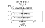
- Each lens 25 to 28 included in the image pickup optical system 20 is designed for infrared IR. Therefore, when the second filter F2 is inserted into the optical path, it cannot be out of focus by moving the zoom lens 27 in order to correct the angle of view difference. Therefore, as shown in FIG. 7, when the second filter F2 is inserted into the optical path, after the focus lens drive control unit 83 moves the focus lens 26 to correct the axial chromatic aberration (step ST10), The zoom lens drive control unit 84 may move the zoom lens 27 once to correct the angle of view difference (step ST11).
- the focus lens drive control unit 83 moves the focus lens 26 to correct the axial chromatic aberration (step ST10) and zoom.
- the focus lens drive control unit 83 moves the focus lens 26 again to adjust the out-of-focus (step ST12). .. Then, these steps ST11 and ST12 are repeated until the angle of view difference becomes an allowable range (YES in step ST13).
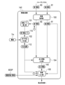
- the image processing unit 81 includes an image acquisition unit 100, a brightness level calculation unit 101, an executionability determination unit 102, a brightness level normalization unit 103, a difference image generation unit 104, and an image output unit 105.
- an image acquisition unit 100 a brightness level calculation unit 101
- an executionability determination unit 102 a brightness level normalization unit 103
- a difference image generation unit 104 a difference image generation unit 104
- an image output unit 105 a difference image generation unit 105.
- the image acquisition unit 100 acquires the first image 60 from the image sensor 21.
- the image acquisition unit 100 performs various image processing such as gradation conversion processing on the acquired first image 60, and then outputs the first image 60 to the luminance level calculation unit 101 and the image output unit 105.
- the image acquisition unit 100 acquires the second image 61 from the image sensor 21, performs various image processing on the second image 61, and then outputs the second image 61 to the luminance level calculation unit 101 and the image output. Output to unit 105.
- the first image 60 and the second image 61 acquired by the image acquisition unit 100 are images in which the angle of view difference is corrected.
- the luminance level calculation unit 101 calculates the first luminance level 110, which is the luminance level of the reflected image RFI included in the first image 60.
- the luminance level calculation unit 101 outputs the calculated first luminance level 110 to the execution enablement determination unit 102. Further, the luminance level calculation unit 101 outputs the calculated first luminance level 110 and the first image 60 to the luminance level normalization unit 103.
- the luminance level calculation unit 101 calculates the second luminance level 111, which is the luminance level of the reflected image RFI included in the second image 61.
- the luminance level calculation unit 101 outputs the calculated second luminance level 111 and the second image 61 to the luminance level normalization unit 103.
- the area of the second image 61 whose pixel value is equal to or higher than the preset threshold value is the area where the radiation image RDI is captured, and the area of the second image 61 whose pixel value is less than the threshold value is the reflection image RFI. Extract as an area to be reflected. Then, the luminance level calculation unit 101 calculates the representative value of the luminance value of the pixel in the region where the reflected image RFI of the second image 61 is captured as the second luminance level 111. Further, the luminance level calculation unit 101 extracts the region of the first image 60 corresponding to the region where the reflected image RFI of the second image 61 is captured as the region where the reflected image RFI of the first image 60 is captured.
- the luminance level calculation unit 101 calculates the representative value of the luminance value of the pixel in the region where the reflected image RFI of the first image 60 is captured as the first luminance level 110.
- the representative value is one of the maximum value, the mode value, the median value, and the average value.
- the area where the reflected image RFI of the first image 60 is captured and the region where the reflected image RFI of the second image 61 is captured may be designated by the user via the monitor device 50.
- the executionability determination unit 102 determines whether or not the process of outputting the difference image 115 between the first image 60 and the second image 61 can be executed based on whether or not the execution conditions related to the threshold value TH and the first luminance level 110 are satisfied. judge.
- the executionability determination unit 102 outputs the executionability determination result 112 to the luminance level normalization unit 103, the difference image generation unit 104, and the image output unit 105.
- Executionability determination unit 102 determines executionability at preset time intervals.
- the preset time interval is, for example, every frame, every few minutes, or every few hours.
- the luminance level normalization unit 103 operates only when the execution condition is satisfied and the determination result 112 from the execution possibility determination unit 102 is "execute".
- the luminance level normalization unit 103 normalizes the first luminance level 110 of the first image 60 according to the second luminance level 111 of the second image 61, thereby normalizing the first image 60 with the first image 60N. do.
- the luminance level normalization unit 103 outputs the normalized first image 60N and the second image 61 to the difference image generation unit 104.
- the difference image generation unit 104 operates only when the execution condition is satisfied and the determination result 112 from the execution possibility determination unit 102 is "execution".
- the difference image generation unit 104 generates the difference image 115 by taking the difference between the pixel values for each corresponding pixel of the normalized first image 60N and the second image 61.
- the difference image generation unit 104 outputs the generated difference image 115 to the image output unit 105.
- the difference image 115 is an example of the "third image" according to the technique of the present disclosure.
- the image output unit 105 transfers the first image 60, the second image 61, and the difference image 115. Output to the control unit 82.
- the transfer control unit 82 transfers the first image 60, the second image 61, and the difference image 115 to the monitor device 50.
- the image output unit 105 transfers the first image 60SP for superimposition and the second image 61. Output to the control unit 82.
- the transfer control unit 82 transfers the first image 60SP for superimposition and the second image 61 to the monitoring device 50. That is, the image output unit 105 outputs the difference image 115 only when the execution condition is satisfied.
- the first image 60SP for superimposition is an image acquired by capturing the reflected image RFI by the image sensor 21 when the first luminance level 110 is equal to or higher than the threshold value TH.
- the first image 60SP for superimposition is acquired by a user's instruction via, for example, the monitoring device 50, and is stored in the storage 67.
- the case where the first luminance level 110 is equal to or higher than the threshold value TH is, for example, daytime.
- the first image 60SP for superimposition may be acquired and stored at a time specified in advance by the user.
- the execution possibility determination unit 102 determines that the execution condition is satisfied, and outputs a determination result 112A having the content of "execute". do.
- the execution possibility determination unit 102 determines that the execution condition is not satisfied, and determines that the execution is not executed.
- the result 112B is output.
- the threshold TH is set to the radiation image RDI depending on the brightness of the reflected image RFI of the second image 61 corresponding to the reflected image RFI of the first image 60 when the first luminance level 110 is a value higher than that. A value is set that makes it difficult to observe.
- FIG. 12 shows a specific example of normalization by the luminance level normalization unit 103.
- the luminance level normalizing unit 103 multiplies the pixel value of each pixel of the first image 60 by 0.8. Then, the first image 60 is defined as the normalized first image 60N.
- FIG. 13 shows the formation of the difference image 115.
- the difference image generation unit 104 generates the difference image 115 by subtracting the normalized first image 60N from the second image 61.
- the second luminance level 111 of the reflected image RFI included in the second image 61 coincides with the first luminance level 110 of the reflected image RFI included in the normalized first image 60N. Therefore, the difference image 115 is an image in which the reflection image RFI of the second image 61 is almost removed and the radiation image RDI is almost the only image.
- the monitor device 50 when the difference image 115 or the like is transferred from the transfer control unit 82, the monitor device 50 generates a superimposed image 120 of the first image 60 and the difference image 115, and the superimposed image 120 is generated. It is presented to the user by being displayed on a display (not shown).
- the superimposed image 120 may be generated by the image processing unit 81 and transferred to the monitoring device 50 by the transfer control unit 82.
- the transfer control unit 82 transfers the first image 60SP for superimposition and the like instead of the difference image 115
- the monitor device 50 transfers the first image 60SP for superimposition and the second image.
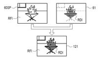
- the superimposed image 121 of 61 is generated, and the superimposed image 121 is displayed on the display and presented to the user.
- edge extraction may be performed on the first image 60 and the difference image 115, and the edges of the first image 60 and the difference image 115 may be superimposed so as to be aligned with each other.
- the area of the radiation image RDI of the superimposed images 120 and 121 may be blinked or colored.
- the edge extraction image of the reflected image RFI of the first image 60 or the first image 60SP for superimposition may be superposed with the difference image 115 or the second image 61.
- the subject light SL passes through the objective lens 25 of the imaging optical system 20, the focus lens 26, the zoom lens 27, the aperture 30, any of the filters F1 and F2 of the filter unit 31, and the master lens 28, and passes through the image sensor 21.
- the image sensor 21 captures the subject light SL and outputs an image.
- the filter unit 31 is rotated clockwise by the filter unit drive mechanism 38 driven under the control of the filter unit drive control unit 86.
- the filters F1 and F2 are sequentially inserted into the optical path every frame.
- the first filter F1 is inserted into the optical path (step ST100).
- the focus lens 26 is moved to the object side OD by the focus lens drive mechanism 35 driven under the control of the focus lens drive control unit 83.
- axial chromatic aberration is corrected (step ST110).
- the zoom lens 27 is moved in the object side direction OD by the zoom lens drive mechanism 36 driven under the control of the zoom lens drive control unit 84.
- the angle of view difference is corrected (step ST120).
- the movement of the zoom lens 27 for correcting the angle of view difference and the movement of the focus lens 26 for focusing are performed until the angle of view difference becomes an allowable range. Repeated.
- the visible light VR transmitted through the first filter F1 is imaged by the image sensor 21, and the first image 60 including the reflected image RFI is output from the image sensor 21.
- the first image 60 is sent from the image sensor 21 to the image acquisition unit 100 of the image processing unit 81, and is acquired by the image acquisition unit 100 (step ST130).
- the second filter F2 is inserted into the optical path (step ST140).
- the focus lens 26 is moved to the image formation side direction ID by the focus lens drive mechanism 35 driven under the control of the focus lens drive control unit 83.
- axial chromatic aberration is corrected (step ST150).
- the zoom lens 27 is moved to the image formation side direction ID by the zoom lens drive mechanism 36 driven under the control of the zoom lens drive control unit 84.
- the angle of view difference is corrected (step ST160).
- the infrared IR transmitted through the second filter F2 is imaged by the image sensor 21, and the second image 61 including the reflected image RFI and the radiation image RDI is output from the image sensor 21. ..
- the second image 61 is sent from the image sensor 21 to the image acquisition unit 100 of the image processing unit 81, and is acquired by the image acquisition unit 100 (step ST170).
- the first image 60 is output from the image acquisition unit 100 to the luminance level calculation unit 101. Then, the luminance level calculation unit 101 calculates the first luminance level 110 of the first image 60. The first luminance level 110 is output to the executionability determination unit 102, and is compared with the threshold value TH in the executionability determination unit 102.
- the determination result 112A having the content of "execute” is obtained from the execution possibility determination unit 102 to the luminance level normalization unit 103 and the difference image generation. It is output to the unit 104 and the image output unit 105 (YES in step ST180).
- the first image 60 is designated as the normalized first image 60N in the luminance level normalizing unit 103.
- the difference image generation unit 104 generates the normalized first image 60N and the difference image 115 of the second image 61.
- the difference image 115 is output from the image output unit 105 to the transfer control unit 82 together with the first image 60 and the second image 61 (step ST190).
- the determination result 112B having the content of "do not execute" is the difference between the luminance level normalization unit 103 and the execution possibility determination unit 102. It is output to the image generation unit 104 and the image output unit 105 (NO in step ST180). In this case, the luminance level normalization unit 103 and the difference image generation unit 104 are not operated, and therefore the difference image 115 is not generated. From the image output unit 105, the first image 60SP for superimposition and the second image 61 are output to the transfer control unit 82. The series of processes of steps ST100 to ST190 is repeated until an image pickup end instruction is input via the monitor device 50.
- the filter unit drive control unit 86 of the CPU 65 selectively inserts the first filter F1 that transmits visible light VR and the second filter F2 that transmits infrared IR into the optical path.
- the focus lens drive control unit 83 moves the focus lens 26 along the optical axis OA to move the on-axis chromatic aberration of the visible light VR transmitted through the first filter F1 and the infrared IR transmitted through the second filter F2. to correct.
- the image sensor drive control unit 80 acquires the first image 60 including the reflected image RFI of the subject by causing the image sensor 21 to image the visible light VR transmitted through the first filter F1.
- the image sensor drive control unit 80 acquires the second image 61 including the reflected image RFI and the radiation image RDI of the subject by causing the image sensor 21 to image the infrared IR transmitted through the second filter F2.
- the zoom lens drive control unit 84 causes the angle of view difference between the first image 60 and the second image 61 caused by moving the focus lens 26 along the optical axis OA, and causes the zoom lens 27 to move the zoom lens 27 along the optical axis OA. Correct by moving.
- the image processing unit 81 outputs a difference image 115 as a third image based on the first image 60 and the second image 61 acquired in a state where the angle of view difference is corrected. Therefore, for example, as shown in FIG.
- the superimposed image 120 of the first image 60 and the difference image 115 can be presented to the user. Therefore, it is possible to present the radiation image RDI to the user in an easy-to-understand manner as compared with the case where the reflection image RFI that hinders the observation of the radiation image RDI is not removed.
- the image processing unit 81 outputs the difference image 115 only when the preset execution conditions are satisfied.
- the execution condition includes the content that the first luminance level 110, which is the luminance level of the reflected image RFI included in the first image 60, is equal to or higher than the preset threshold value TH. Therefore, when the radiation image RDI can be sufficiently observed without removing the reflected image RFI, such as at night, it is possible to save the trouble of generating and outputting the difference image 115. In other words, the difference image 115 can be generated and output only when necessary. Even at night, when the illumination light is irradiated and the first luminance level 110 is equal to or higher than the threshold value TH, the difference image 115 is generated and output.
- the image processing unit 81 acquires and stores in advance when the first luminance level 110 is less than the threshold value TH and when the first luminance level 110 is equal to or higher than the threshold value TH.
- the first image 60SP for use and the second image 61 acquired in a state where the angle of view difference is corrected are output. Therefore, for example, as shown in FIG. 15, the superimposed image 121 of the first image 60SP for superimposition and the second image 61 can be presented to the user. Therefore, even when it is difficult to visually recognize the reflected image RFI, such as at night, it is possible to grasp which part of the subject has a high temperature.
- the image processing unit 81 has a first luminance level 110 of the reflected image RFI included in the first image 60 and a second luminance level 111 of the reflected image RFI included in the second image 61. After matching with, the difference image 115 is generated. Therefore, the reflected image RFI included in the second image 61 can be almost eliminated, and the radiation image RDI can be observed without being disturbed by the reflected image RFI.
- the zoom lens drive control unit 84 changes the amount of movement of the zoom lens 27 required for correcting the angle of view difference according to the position of the zoom lens 27 when the axial chromatic aberration is corrected. Therefore, the angle of view difference can be appropriately corrected according to the position of the zoom lens 27.
- the focus lens drive control unit 83 adjusts the focus shifted by moving the zoom lens 27 when correcting the angle of view difference by moving the focus lens 26. Therefore, it is possible to acquire the first image 60 in which the difference in angle of view is corrected and the image is in focus.
- the imaging optical system 20 may include other optical elements such as a half mirror or a polarizing element.
- the filter unit 31 is not limited to the space between the aperture 30 and the master lens 28, and may be arranged, for example, between the zoom lens 27 and the aperture 30, or in the rear stage of the master lens 28. Further, the filter unit 31 may be arranged in front of the image sensor 21 of the main body 12 instead of the lens barrel 11.
- the camera 10 in which the lens barrel 11 and the main body 12 can be removed is illustrated, but the present invention is not limited to this.
- the lens barrel 11 and the main body 12 may not be removable and may be an integrated camera.
- the filter unit 31 may include an optical path length adjusting filter or a dimming filter in addition to the first filter F1 and the second filter F2. Further, the wavelength band of the visible light VR transmitted through the first filter F1 is not limited to the exemplified 400 nm to 770 nm. The wavelength band of the infrared IR transmitted through the second filter F2 is also not limited to the exemplified 1450 nm to 1650 nm.
- the execution condition is that the first luminance level 110 is equal to or higher than the threshold value TH, but the execution condition is not limited to this.
- the CPU of the second embodiment functions as an instruction receiving unit 130 in addition to each unit of the first embodiment.
- the instruction receiving unit 130 receives an instruction input by the user via the monitoring device 50.
- the instruction includes an instruction to execute the output of the difference image 115 (hereinafter referred to as an execution instruction) and an instruction to cancel the execution instruction (hereinafter referred to as a cancellation instruction).
- an execution instruction an instruction to execute the output of the difference image 115
- a cancellation instruction an instruction to cancel the execution instruction
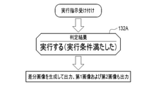
- the instruction receiving unit 130 outputs to the execution possibility determination unit 131 that the execution instruction has been accepted.
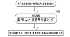
- the instruction receiving unit 130 outputs to the executionability determination unit 131 that the cancellation instruction has been accepted.
- the executionability determination unit 131 determines the executionability determination result 132 of the process of outputting the difference image 115 of the first image 60 and the second image 61, the luminance level normalization unit 103, the difference image generation unit 104, and the difference image generation unit 104, which are not shown. It is output to the image output unit 105.
- the execution possibility determination unit 131 determines that the execution condition is satisfied, and outputs a determination result 132A having the content of "execute".
- the execution possibility determination unit 131 does not satisfy the execution condition when the instruction receiving unit 130 does not receive the execution instruction or when the instruction receiving unit 130 receives the cancellation instruction. It is determined that the result is 132B, and the determination result 132B with the content of "do not execute" is output.
- the execution condition includes the content that the instruction to execute the output of the difference image 115 is accepted. Therefore, it is possible to determine whether or not the process of outputting the difference image 115 can be executed according to the user's intention.
- the execution condition is the embodiment of the first embodiment in which the first luminance level 110 is equal to or higher than the threshold value TH, and the execution condition is that the instruction to execute the output of the difference image 115 is accepted.
- the aspect of the second embodiment may be configured to be selectable by the user.
- the execution enablement determination unit 131 outputs the difference image 115 when the first luminance level 110 is equal to or higher than the threshold value TH.
- the difference image 115 is generated after matching the first luminance level 110 and the second luminance level 111, but the present invention is not limited to this.
- the image processing unit 140 of the third embodiment is different from the image processing unit 81 of the first embodiment in that the brightness level normalization unit 103 is not provided. Further, the image acquisition unit 100 outputs only the first image 60 to the luminance level calculation unit 101, and the luminance level calculation unit 101 calculates only the first luminance level 110.
- the image acquisition unit 100 directly outputs the first image 60 and the second image 61 to the difference image generation unit 104.
- the difference image generation unit 104 generates the difference image 145 of the first image 60 and the second image 61, and outputs the generated difference image 145 to the image output unit 105.
- the difference image generation unit 104 generates the difference image 145 by subtracting the first image 60 from the second image 61.
- the second luminance level 111 of the reflected image RFI included in the second image 61 and the first luminance level 110 of the reflected image RFI included in the first image 60 are the first luminance level 110 as in the first embodiment. It is different because it has not been normalized. Therefore, the difference image 145 is an image in which the reflected image RFI of the second image 61 remains to some extent as compared with the difference image 115 of the first embodiment.
- the first luminance level 110 of the reflected image RFI included in the first image 60 and the second luminance level 111 of the reflected image RFI included in the second image 61 do not match.
- the difference image 145 is generated. Therefore, as shown in FIG. 22 as an example, when the superposed image 150 of the first image 60 and the difference image 145 is generated in the monitor device 50, the first image is determined by the reflected image RFI remaining in the difference image 145. The alignment between the 60 and the difference image 145 can be performed accurately.
- the master lens 28 is used to correct the axial chromatic aberration in addition to the focus lens 26.
- the camera 200 of the fourth embodiment includes a lens barrel 201 and a main body 12.
- the lens barrel 201 has substantially the same configuration as the lens barrel 11 of the first embodiment, except that the master lens drive mechanism 202 is connected to the master lens 28.
- the same parts as those in the first embodiment are designated by the same reference numerals, and the description thereof will be omitted.
- the master lens drive mechanism 202 holds the master lens 28, and has a master cam ring having a cam groove formed on the outer periphery and a master cam ring as an optical axis. It includes a master motor and the like that move the master cam ring along the optical axis OA by rotating around the OA.
- the master motor is driven under the control of the control unit 205.
- the master motor is a stepping motor, and the control unit 205 derives the position of the master lens 28 on the optical axis OA from the driving amount of the master motor.
- the control unit 205 corrects the axial chromatic aberration of a plurality of types of light transmitted through the filters F1 and F2 by moving the focus lens 26 along the optical axis OA via the focus lens drive mechanism 35. Further, the control unit 205 corrects the axial chromatic aberration of a plurality of types of light transmitted through the filters F1 and F2 by moving the master lens 28 along the optical axis OA via the master lens drive mechanism 202. That is, in the fourth embodiment, the master lens 28 in addition to the focus lens 26 is also an example of the “correction lens” according to the technique of the present disclosure.
- the control unit 205 first detects the position of the zoom lens 27 (step ST500).
- the detected position of the zoom lens 27 is on the telephoto side of the preset threshold value, that is, when the zoom lens 27 is located on the telephoto side of the preset threshold value (YES in step ST510).
- the control unit 205 corrects the axial chromatic aberration by moving the focus lens 26 along the optical axis OA via the focus lens drive mechanism 35 (step ST520).
- the control unit 205 determines. By moving the master lens 28 along the optical axis OA via the master lens drive mechanism 202, axial chromatic aberration is corrected (step ST530).
- the zoom lens 27 when the zoom lens 27 is located on the telephoto side of the preset threshold value, the focus lens 26 moves to correct the axial chromatic aberration and the zoom lens is closer to the threshold value.
- the master lens 28 moves to correct axial chromatic aberration.
- the zoom lens 27 is located on the telephoto side, the amount of movement required for correcting the axial chromatic aberration is smaller in the focus lens 26 than in the master lens 28. Therefore, when the zoom lens 27 is located on the telephoto side of the preset threshold value, the focus lens 26 moves, so that the time required for correcting the axial chromatic aberration can be shortened.
- the zoom lens 27 when the zoom lens 27 is located on the wide-angle side, the amount of movement required for correcting the axial chromatic aberration is smaller in the master lens 28 than in the focus lens 26. Therefore, when the zoom lens 27 is located on the wide-angle side of the preset threshold value, the time required for correcting the axial chromatic aberration can be shortened by moving the master lens 28.
- the axial chromatic aberration may be corrected by moving the focus lens 26 and the master lens 28 in parallel.
- the difference images 115 and 145 are exemplified as the third image, but the present invention is not limited to this.
- the zoom function is not limited to the illustrated optical zoom function 90.
- An electronic zoom function may be used in addition to or instead of the optical zoom function 90.
- the first image 60SP for superimposition may be transferred to the monitor device 50 for each frame, or may be transferred to the monitor device 50 only once. When transferring only once, the first image 60SP for superimposition is stored in the monitoring device 50 and reused.
- the cameras 10 and 200 which are surveillance cameras installed in factories and the like, are shown as an example of the "imaging device" according to the technique of the present disclosure, but the present invention is not limited to this.
- a digital camera used by a general user, a smart device, or the like may be used.
- control units 45 and 205 corresponding to the image pickup control device of the present disclosure are mounted on the cameras 10 and 200 are exemplified, but the present invention is not limited to this.
- the image pickup control device of the present disclosure may be mounted on the monitor device 50.
- the image sensor drive control unit 80 for example, the image sensor drive control unit 80, the image processing units 81 and 140, the transfer control unit 82, the focus lens drive control unit 83, the zoom lens drive control unit 84, the aperture drive control unit 85, and the filter unit drive.
- Various processes such as a control unit 86, an image acquisition unit 100, a brightness level calculation unit 101, an executeability determination unit 102 and 131, a brightness level normalization unit 103, a difference image generation unit 104, an image output unit 105, and an instruction reception unit 130.
- various processors (Processors) shown below can be used as the hardware structure of the processing unit (Processing Unit) that executes the above.
- processor 65 which is a general-purpose processor that executes software (operation program 70) and functions as various processing units, after manufacturing an FPGA (Field Programgable Gate Array) or the like.
- FPGA Field Programgable Gate Array
- Dedicated processor with a circuit configuration specially designed to execute specific processing such as programmable logic device (PLD), ASIC (Application Specific Integrated Circuit), which is a processor whose circuit configuration can be changed. Includes electrical circuits and the like.
- One processing unit may be composed of one of these various processors, or may be a combination of two or more processors of the same type or different types (for example, a combination of a plurality of FPGAs and / or a CPU). It may be configured in combination with FPGA). Further, a plurality of processing units may be configured by one processor.
- one processor is configured by a combination of one or more CPUs and software, as represented by a computer such as a client and a server.
- the processor functions as a plurality of processing units.
- SoC System On Chip
- SoC system On Chip
- the various processing units are configured by using one or more of the above-mentioned various processors as a hardware-like structure.
- an electric circuit in which circuit elements such as semiconductor elements are combined can be used.
- the technique of the present disclosure can be appropriately combined with the various embodiments described above and / or various modifications. Further, it is of course not limited to each of the above embodiments, and various configurations can be adopted as long as they do not deviate from the gist. Further, the technique of the present disclosure extends to a storage medium for storing the program non-temporarily in addition to the program.
- a and / or B is synonymous with "at least one of A and B". That is, “A and / or B” means that it may be A alone, B alone, or a combination of A and B. Further, in the present specification, when three or more matters are connected and expressed by "and / or", the same concept as “A and / or B" is applied.
- Control unit 50 Monitor device 51 Connector 60 1st image 60N Normalization 1st image 60SP 1st image for superimposition 61st 2 image 65 CPU 66 Memory 67 Storage 70 Operation program 71 Zoom lens movement amount information 80 Image sensor drive control unit 81, 140 Image processing unit 82 Transfer control unit 83 Focus lens drive control unit 84 Zoom lens drive control unit 85 Aperture drive control unit 86 Filter unit drive Control unit 90 Optical zoom function 100 Image acquisition unit 101 Brightness level calculation unit 102, 131 Executability determination unit 103 Brightness level normalization unit 104 Difference image generation unit 105 Image output unit 110 First brightness level 111 Second brightness level 112, 112A , 112B, 132,
Landscapes
- Engineering & Computer Science (AREA)
- Multimedia (AREA)
- Signal Processing (AREA)
- General Physics & Mathematics (AREA)
- Physics & Mathematics (AREA)
- Theoretical Computer Science (AREA)
- Software Systems (AREA)
- Computer Vision & Pattern Recognition (AREA)
- Health & Medical Sciences (AREA)
- General Health & Medical Sciences (AREA)
- Medical Informatics (AREA)
- Evolutionary Computation (AREA)
- Databases & Information Systems (AREA)
- Computing Systems (AREA)
- Artificial Intelligence (AREA)
- Studio Devices (AREA)
- Blocking Light For Cameras (AREA)
Priority Applications (2)
| Application Number | Priority Date | Filing Date | Title |
|---|---|---|---|
| JP2022540075A JP7430801B2 (ja) | 2020-07-29 | 2021-06-24 | 撮像制御装置、撮像制御装置の作動方法、プログラム、並びに撮像装置 |
| US18/152,117 US12192602B2 (en) | 2020-07-29 | 2023-01-09 | Imaging control device, operation method and program of imaging control device, and imaging device |
Applications Claiming Priority (2)
| Application Number | Priority Date | Filing Date | Title |
|---|---|---|---|
| JP2020-128580 | 2020-07-29 | ||
| JP2020128580 | 2020-07-29 |
Related Child Applications (1)
| Application Number | Title | Priority Date | Filing Date |
|---|---|---|---|
| US18/152,117 Continuation US12192602B2 (en) | 2020-07-29 | 2023-01-09 | Imaging control device, operation method and program of imaging control device, and imaging device |
Publications (1)
| Publication Number | Publication Date |
|---|---|
| WO2022024612A1 true WO2022024612A1 (ja) | 2022-02-03 |
Family
ID=80035489
Family Applications (1)
| Application Number | Title | Priority Date | Filing Date |
|---|---|---|---|
| PCT/JP2021/023987 Ceased WO2022024612A1 (ja) | 2020-07-29 | 2021-06-24 | 撮像制御装置、撮像制御装置の作動方法、プログラム、並びに撮像装置 |
Country Status (3)
| Country | Link |
|---|---|
| US (1) | US12192602B2 (https=) |
| JP (1) | JP7430801B2 (https=) |
| WO (1) | WO2022024612A1 (https=) |
Families Citing this family (2)
| Publication number | Priority date | Publication date | Assignee | Title |
|---|---|---|---|---|
| US11836825B1 (en) * | 2022-05-23 | 2023-12-05 | Dell Products L.P. | System and method for detecting postures of a user of an information handling system (IHS) during extreme lighting conditions |
| JP2025110526A (ja) * | 2024-01-16 | 2025-07-29 | キヤノン株式会社 | レンズ装置およびその制御方法 |
Citations (4)
| Publication number | Priority date | Publication date | Assignee | Title |
|---|---|---|---|---|
| JP2006033716A (ja) * | 2004-07-21 | 2006-02-02 | Hitachi Maxell Ltd | 撮像装置 |
| WO2016171088A1 (ja) * | 2015-04-23 | 2016-10-27 | 富士フイルム株式会社 | 撮像装置及び撮像装置の画像処理方法及びプログラム |
| JP2018195085A (ja) * | 2017-05-17 | 2018-12-06 | キヤノン株式会社 | 画像処理装置、撮像装置、画像処理方法、及びプログラム |
| JP2019205180A (ja) * | 2019-07-02 | 2019-11-28 | 株式会社四国総合研究所 | 水素火炎監視装置および水素取扱施設 |
Family Cites Families (6)
| Publication number | Priority date | Publication date | Assignee | Title |
|---|---|---|---|---|
| JPS6211384A (ja) | 1985-07-09 | 1987-01-20 | Toshiba Corp | Tvカメラ監視装置 |
| JP4505151B2 (ja) | 2001-01-10 | 2010-07-21 | 株式会社日立国際電気 | 撮像装置 |
| JP2004354714A (ja) | 2003-05-29 | 2004-12-16 | Fuji Photo Optical Co Ltd | 可視光・赤外光撮影用レンズシステム |
| JP2006003589A (ja) * | 2004-06-17 | 2006-01-05 | Fujinon Corp | バリフォーカルレンズ |
| JP5706798B2 (ja) * | 2011-10-21 | 2015-04-22 | 株式会社タムロン | ズームレンズ |
| JP6247425B2 (ja) * | 2015-04-23 | 2017-12-13 | 富士フイルム株式会社 | 画像処理装置、撮像装置、画像処理方法及び画像処理プログラム |
-
2021
- 2021-06-24 WO PCT/JP2021/023987 patent/WO2022024612A1/ja not_active Ceased
- 2021-06-24 JP JP2022540075A patent/JP7430801B2/ja active Active
-
2023
- 2023-01-09 US US18/152,117 patent/US12192602B2/en active Active
Patent Citations (4)
| Publication number | Priority date | Publication date | Assignee | Title |
|---|---|---|---|---|
| JP2006033716A (ja) * | 2004-07-21 | 2006-02-02 | Hitachi Maxell Ltd | 撮像装置 |
| WO2016171088A1 (ja) * | 2015-04-23 | 2016-10-27 | 富士フイルム株式会社 | 撮像装置及び撮像装置の画像処理方法及びプログラム |
| JP2018195085A (ja) * | 2017-05-17 | 2018-12-06 | キヤノン株式会社 | 画像処理装置、撮像装置、画像処理方法、及びプログラム |
| JP2019205180A (ja) * | 2019-07-02 | 2019-11-28 | 株式会社四国総合研究所 | 水素火炎監視装置および水素取扱施設 |
Also Published As
| Publication number | Publication date |
|---|---|
| US12192602B2 (en) | 2025-01-07 |
| US20230171474A1 (en) | 2023-06-01 |
| JP7430801B2 (ja) | 2024-02-13 |
| JPWO2022024612A1 (https=) | 2022-02-03 |
Similar Documents
| Publication | Publication Date | Title |
|---|---|---|
| US11712156B2 (en) | Image pickup device, microscope image pickup system, and endoscope image pickup system | |
| US11786120B2 (en) | Dynamic eye fixation for retinal imaging | |
| US12192602B2 (en) | Imaging control device, operation method and program of imaging control device, and imaging device | |
| US20120050672A1 (en) | Fundus imaging apparatus | |
| US10785402B2 (en) | Imaging device and focusing control method of imaging device | |
| US12309349B2 (en) | Stereoscopic imaging platform with disparity and sharpness control automatic focusing mode | |
| JP2010160312A (ja) | 可視光・赤外光撮影用レンズアダプタ | |
| US10209786B2 (en) | Projector system | |
| US20260016702A1 (en) | Lens device, imaging apparatus, operation method of lens device, operation method of imaging apparatus, and program | |
| CN110876023A (zh) | 摄像设备、监视系统、摄像设备的控制方法和存储介质 | |
| WO2020213595A1 (ja) | 交換レンズ、情報処理装置、情報処理方法、及び、プログラム | |
| JP2018056799A (ja) | プロジェクターシステム及び撮像装置 | |
| US10254528B2 (en) | Microscope insert | |
| JP7483368B2 (ja) | 画像処理装置、制御方法およびプログラム | |
| JP2004354714A (ja) | 可視光・赤外光撮影用レンズシステム | |
| JP2010102281A (ja) | 可視光・赤外光撮影用レンズアダプタ | |
| JP7814915B2 (ja) | 光学装置 | |
| JP2006346196A (ja) | 内視鏡撮像システム | |
| WO2016208125A1 (en) | Image detection device and image detection system | |
| HK1247068A1 (en) | Ocular fundus imaging system | |
| US9671281B2 (en) | Imaging systems with digital micromirror devices (DMD) | |
| CN107924107B (zh) | 摄像装置 | |
| JP2011150203A (ja) | レンズバレルのフォーカス調整装置およびフォーカス調整方法 | |
| JP7814916B2 (ja) | 光学装置 | |
| US12492944B2 (en) | Imaging control device, imaging apparatus, imaging control method, and program |
Legal Events
| Date | Code | Title | Description |
|---|---|---|---|
| 121 | Ep: the epo has been informed by wipo that ep was designated in this application |
Ref document number: 21849064 Country of ref document: EP Kind code of ref document: A1 |
|
| ENP | Entry into the national phase |
Ref document number: 2022540075 Country of ref document: JP Kind code of ref document: A |
|
| NENP | Non-entry into the national phase |
Ref country code: DE |
|
| 122 | Ep: pct application non-entry in european phase |
Ref document number: 21849064 Country of ref document: EP Kind code of ref document: A1 |