WO2022022243A1 - 一种双稳态能量收集器离心距离优化匹配方法 - Google Patents
一种双稳态能量收集器离心距离优化匹配方法 Download PDFInfo
- Publication number
- WO2022022243A1 WO2022022243A1 PCT/CN2021/104855 CN2021104855W WO2022022243A1 WO 2022022243 A1 WO2022022243 A1 WO 2022022243A1 CN 2021104855 W CN2021104855 W CN 2021104855W WO 2022022243 A1 WO2022022243 A1 WO 2022022243A1
- Authority
- WO
- WIPO (PCT)
- Prior art keywords
- centrifugal
- magnet
- cantilever beam
- equation
- energy
- Prior art date
- Legal status (The legal status is an assumption and is not a legal conclusion. Google has not performed a legal analysis and makes no representation as to the accuracy of the status listed.)
- Ceased
Links
Images


Classifications
-
- H—ELECTRICITY
- H02—GENERATION; CONVERSION OR DISTRIBUTION OF ELECTRIC POWER
- H02N—ELECTRIC MACHINES NOT OTHERWISE PROVIDED FOR
- H02N2/00—Electric machines in general using piezoelectric effect, electrostriction or magnetostriction
- H02N2/18—Electric machines in general using piezoelectric effect, electrostriction or magnetostriction producing electrical output from mechanical input, e.g. generators
- H02N2/186—Vibration harvesters
Definitions
- the invention relates to the technical field of bistable energy collectors, in particular to a method for optimizing the centrifugal distance of a bistable energy collector.
- centrifugal distance is set by the estimation method or the empirical method to further simulate and study its efficiency.
- the performance and efficiency of the energy harvester are very sensitive to the centrifugal distance, even in the order of magnitude of 0.0001 m.
- the present invention provides the following scheme:
- a method for optimizing the centrifugal distance of a bistable energy harvester comprises the following steps:
- Step 1 establish the kinetic model of the bistable energy harvester with centrifugal effect
- Step 2 carry out a working simulation of the bistable energy harvester
- Step 3 During the vibration of the cantilever beam, the magnetic force received by the magnet is F M , and the tangential component force is F H ;
- F N is the pressure received by the magnet at the end of the cantilever beam, and
- Step 4 The dynamic equation of the bistable energy harvesting system based on the magnet oscillating in the high-energy potential energy well is expressed as where m is the mass of the magnet at the end of the cantilever beam; c is the damping; k is the initial stiffness of the cantilever beam; L is the length of the cantilever beam; r is the distance from the center of rotation to the root of the cantilever beam; The distance between the centers of rotation; a is the linear coefficient of the magnet force; b is the nonlinear coefficient of the magnet force;
- Step 6 The frequency equation of the lower jump point is The better the fitting effect of the ⁇ curve and the frequency curve ⁇ is, the higher the energy of the corresponding monostable high-energy orbit after the drift, and the wider the frequency band.
- the equation is a complex domain equation, ⁇ is the frequency value corresponding to the position where the trajectory of the lower jump point and the frequency curve intersect, and ⁇ only takes positive real roots.
- a further improvement lies in: the frequency corresponding to the position where the locus of the jump point and ⁇ intersects when the centrifugal distance H effect is optimal is:
- the effective collection frequency band is the widest.
- the invention further improves the energy collection efficiency of the bistable energy collector and widens the effective collection frequency band by adjusting the installation centrifugal distance of the magnet at the end of the cantilever beam.
- the calculation equation of the optimal centrifugal distance is deduced, which can greatly shorten the installation and debugging time of magnets at different centrifugal distances when the centrifugal effect is used to improve the bistable energy harvester.
- the rotation frequency corresponding to the most efficient energy harvesting efficiency under the optimal centrifugal distance H is deduced. In this way, bistable energy harvesters with different parameters can be designed to adapt to rotating machines (vehicles) that often work at a fixed rotational frequency (vehicle speed), and further improve the performance and efficiency of bistable energy harvesters.
- Fig. 1 is the kinetic model diagram of the bistable energy harvester of centrifugal effect of the present invention
- Fig. 2 is the force analysis diagram of the cantilever beam end magnet of the present invention
- FIG. 3 is a matching diagram of the ⁇ curve and the frequency curve under different centrifugal distances of the present invention.
- the dynamic model of the centrifugal effect bistable energy harvester includes a frame 1, a magnet 2, a cantilever beam 3, a piezoelectric sheet 4 and a rotation center 5, and the frame 1 is installed on the rotating environment (disc) , the magnet 2 includes a fixed magnet and a tip magnet; the fixed magnet is fixed on the frame 1 through lifting ears or using strong glue, the tip magnet is fixed on the end of the cantilever beam 3 with strong glue, and the piezoelectric sheet 4 is pasted on both sides of the cantilever beam 3,
- the cantilever beam 3 is fixed on the rotating disk through the lifting lugs and ensures that the straight line where the cantilever beam 3 is located passes the rotation center 5 , which is the rotation center 5 of the disk and the rotation center 5 of the rotating shaft.
- This embodiment provides a method for optimizing the centrifugal distance of a bistable energy harvester, and the matching method includes the following steps:
- Step 1 Establish the kinetic model of the bistable energy harvester with centrifugal effect.
- Step 2 Carry out a working simulation of the bistable energy harvester.
- Step 3 During the vibration of the cantilever beam, as shown in Figure 2, the magnetic force received by the magnet is F M , and the tangential component force is F H ; F N is the pressure on the magnet at the end of the cantilever beam, and F C is the magnet at the end of the cantilever beam.
- F H F M sin ⁇
- ⁇ is the volume of the magnet
- ⁇ is the magnetic permeability in vacuum
- Mf (M fx , M fy )
- M fx is the magnetization amplitude of the magnet installed on the rack in the horizontal direction
- M fy is the magnetization amplitude of the magnet installed on the rack in the vertical direction
- M cx is the magnetization of the tip magnet in the horizontal direction
- M cy is the magnetization amplitude of the tip magnet in the vertical direction
- x r is the real-time displacement of the tip magnet
- d is the distance between the magnet installed on the rack and the tip magnet.
- Step 4 The dynamic equation of the bistable energy harvesting system based on the magnet oscillating in the high-energy potential energy well is expressed as where m is the mass of the magnet at the end of the cantilever beam; c is the damping; k is the initial stiffness of the cantilever beam; L is the length of the cantilever beam; r is the distance from the center of rotation to the root of the cantilever beam; The distance between the centers of rotation; a is the linear coefficient of the magnetic force; b is the nonlinear coefficient of the magnetic force, is the acceleration of the vertical vibration of the tip magnet, is the vertical vibration velocity of the tip magnet, x r is the vertical vibration displacement of the tip magnet, ⁇ is the rotational angular velocity, G is the equivalent gravity of the tip magnet, and ⁇ t+ ⁇ 0 is the real-time phase angle during the rotation of the tip magnet.
- Step 6 The frequency equation of the lower jump point is The better the fitting effect between the ⁇ curve and the frequency curve ⁇ , the higher the energy of the monostable high-energy orbit after the corresponding drift and the wider the frequency band.
- Figure 3 shows the matching diagram of the ⁇ curve and the frequency curve under different centrifugal distances.
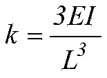
- the frequency corresponding to the position where the trajectory of the jump point intersects with ⁇ is is the bending stiffness of the cantilever beam
- E is the elastic modulus of the cantilever beam material
- I is the moment of inertia of the cantilever beam section, at this time
- the effective collection frequency band is the widest.
Landscapes
- General Electrical Machinery Utilizing Piezoelectricity, Electrostriction Or Magnetostriction (AREA)
- Structures Of Non-Positive Displacement Pumps (AREA)
Abstract
Description


Claims (4)
- 一种双稳态能量收集器离心距离优化匹配方法,其特征在于:所述匹配方法包括以下步骤:步骤一:建立离心效应的双稳态能量采集器的动力学模型;步骤二:对双稳态能量采集器进行工作模拟;步骤三:悬臂梁在振动过程中,磁铁受到的磁力为F M,切向分力为F H;F N为悬臂梁末端磁铁受到的压力,F C为悬臂梁末端磁铁受到的离心力,则

 其中:ν是磁铁的体积;μ是真空中的磁导率;Mf=(M fx,M fy),Mc=(M cx,M cy)是安装在机架上的永磁体的磁化强度振幅和磁端质量;
 步骤四:基于磁体在高能势能阱中振荡的双稳态能量采集系统的动力学方程表示为
 其中m为悬臂梁末端磁铁质量;c为阻尼;k为初始时悬臂梁刚度;L为悬臂梁长度;r为旋转中心距离悬臂梁根部的距离;H≈L+r为悬臂梁末端磁铁质心与旋转中心间的距离;a为磁铁力的线性系数;b为磁铁力的非线性系数;
 步骤五:运用谐波振动法求解动力学方程,设x=B+Xcosωt,则
 步骤六:下跳点频率方程为γ曲线与频率曲线ω的拟合效果越好,则对应漂移后的单稳态高能轨道能量越高,频带越宽。
- 如权利要求1所述的一种双稳态能量收集器离心距离优化匹配方法,其特征在于:当γ曲线与频率曲线ω相切时的离心距离H的求解:令γ=ω,化简有:方程为复数域方程,ω为下跳点轨迹与频率曲线相交处位置对应的频率值,且ω只取正实根。

- 如权利要求2所述的一种双稳态能量收集器离心距离优化匹配方法,其特征在于:所述离心距离H的求解方程中令W=ω 2,且W仅取正值,方程化简为上述方程看作关于W的一元二次方程,由一元二次方程求根公式:

 γ曲线与频率曲线ω相切,即对应方程仅有一个实根,Δ=16m 2(a-k) 2+(16m 2-24m 2H/L)·3mbG 2/c 2=0,即:H=(2/3+2(a-k) 2c 2/9mbG 2)L,此时的离心距离H的离心效应最优,有效收集频带最宽。
- 如权利要求3所述的一种双稳态能量收集器离心距离优化匹配方 法,其特征在于:所述离心距离H效应最优时下跳点轨迹与ω相交处位置对应的频率值为
 为悬臂梁的抗弯刚度,E为悬臂梁材料的弹性模量,I为悬臂梁截面惯性矩,此时
 即:
即: 时系统的能量收集效率最优,有效收集频带最宽。
Priority Applications (1)
| Application Number | Priority Date | Filing Date | Title |
|---|---|---|---|
| GB2116209.4A GB2603033A (en) | 2020-07-31 | 2021-07-07 | Bistable energy collector centrifugal distance optimal matching method |
Applications Claiming Priority (2)
| Application Number | Priority Date | Filing Date | Title |
|---|---|---|---|
| CN202010759431.1 | 2020-07-31 | ||
| CN202010759431.1A CN111953230B (zh) | 2020-07-31 | 2020-07-31 | 一种双稳态能量收集器离心距离优化匹配方法 |
Publications (1)
| Publication Number | Publication Date |
|---|---|
| WO2022022243A1 true WO2022022243A1 (zh) | 2022-02-03 |
Family
ID=73339811
Family Applications (1)
| Application Number | Title | Priority Date | Filing Date |
|---|---|---|---|
| PCT/CN2021/104855 Ceased WO2022022243A1 (zh) | 2020-07-31 | 2021-07-07 | 一种双稳态能量收集器离心距离优化匹配方法 |
Country Status (2)
| Country | Link |
|---|---|
| CN (1) | CN111953230B (zh) |
| WO (1) | WO2022022243A1 (zh) |
Cited By (4)
| Publication number | Priority date | Publication date | Assignee | Title |
|---|---|---|---|---|
| CN115001313A (zh) * | 2022-06-28 | 2022-09-02 | 西北工业大学深圳研究院 | 低频屈曲式双稳态压电俘能装置 |
| CN115242127A (zh) * | 2022-08-02 | 2022-10-25 | 上海交通大学 | 多稳态悬臂梁式压电振动俘能器及设计方法 |
| CN115618668A (zh) * | 2022-12-01 | 2023-01-17 | 河北工业大学 | 一种悬臂梁式磁-机-电复合式混合能量采集器建模方法 |
| CN117212376A (zh) * | 2023-09-07 | 2023-12-12 | 东北大学 | 一种多稳态非线性能量阱以及车辆动力传动系统当量模型 |
Families Citing this family (4)
| Publication number | Priority date | Publication date | Assignee | Title |
|---|---|---|---|---|
| CN111953230B (zh) * | 2020-07-31 | 2023-05-09 | 江苏大学 | 一种双稳态能量收集器离心距离优化匹配方法 |
| GB2603033A (en) * | 2020-07-31 | 2022-07-27 | Univ Jiangsu | Bistable energy collector centrifugal distance optimal matching method |
| CN112671261B (zh) * | 2020-12-18 | 2023-07-21 | 上海科技大学 | 瞬态运动能量收集器及瞬态运动供能物联网传感节点设备 |
| CN114221575A (zh) * | 2021-12-09 | 2022-03-22 | 江苏大学 | 双稳态旋转随机共振能量采集器及离心距离优化匹配方法 |
Citations (6)
| Publication number | Priority date | Publication date | Assignee | Title |
|---|---|---|---|---|
| CN102064745A (zh) * | 2010-11-15 | 2011-05-18 | 中国人民解放军国防科学技术大学 | 一种双稳压电悬臂梁振子装置 |
| US20140035438A1 (en) * | 2011-04-12 | 2014-02-06 | Massachusetts Institute Of Technology | Passive, Self-Tuning Energy Harvester for Extracting Energy From Rotational Motion |
| CN106124036A (zh) * | 2016-08-17 | 2016-11-16 | 西南交通大学 | 一种新型拾振器及其优化设计方法 |
| CN109104123A (zh) * | 2018-10-21 | 2018-12-28 | 吉林大学 | 一种宽频域自调谐双稳态振动能量采集器及采集方法 |
| CN109940613A (zh) * | 2019-03-08 | 2019-06-28 | 南京理工大学 | 一种计算含压电材料机械臂动力学响应及控制的仿真方法 |
| CN111953230A (zh) * | 2020-07-31 | 2020-11-17 | 江苏大学 | 一种双稳态能量收集器离心距离优化匹配方法 |
Family Cites Families (3)
| Publication number | Priority date | Publication date | Assignee | Title |
|---|---|---|---|---|
| CN101656493B (zh) * | 2009-09-17 | 2011-07-27 | 上海交通大学 | 基于双稳态升频结构的mems宽频压电能量采集器 |
| CN104578911B (zh) * | 2015-01-31 | 2016-10-05 | 张文明 | 基于双稳态的无接触磁力式振动能量俘获器 |
| CN106849752B (zh) * | 2017-04-13 | 2018-08-17 | 上海交通大学 | 基于仿生鱼的流致振动能量采集装置 |
-
2020
- 2020-07-31 CN CN202010759431.1A patent/CN111953230B/zh active Active
-
2021
- 2021-07-07 WO PCT/CN2021/104855 patent/WO2022022243A1/zh not_active Ceased
Patent Citations (6)
| Publication number | Priority date | Publication date | Assignee | Title |
|---|---|---|---|---|
| CN102064745A (zh) * | 2010-11-15 | 2011-05-18 | 中国人民解放军国防科学技术大学 | 一种双稳压电悬臂梁振子装置 |
| US20140035438A1 (en) * | 2011-04-12 | 2014-02-06 | Massachusetts Institute Of Technology | Passive, Self-Tuning Energy Harvester for Extracting Energy From Rotational Motion |
| CN106124036A (zh) * | 2016-08-17 | 2016-11-16 | 西南交通大学 | 一种新型拾振器及其优化设计方法 |
| CN109104123A (zh) * | 2018-10-21 | 2018-12-28 | 吉林大学 | 一种宽频域自调谐双稳态振动能量采集器及采集方法 |
| CN109940613A (zh) * | 2019-03-08 | 2019-06-28 | 南京理工大学 | 一种计算含压电材料机械臂动力学响应及控制的仿真方法 |
| CN111953230A (zh) * | 2020-07-31 | 2020-11-17 | 江苏大学 | 一种双稳态能量收集器离心距离优化匹配方法 |
Non-Patent Citations (2)
| Title |
|---|
| FU MEI-ZHEN, SHU-YING CAO, LIN-FEI QU, JIA-JU ZHENG, BO-WEN WANG: "Dynamic Characteristics of Bistable Magnetostrictive Energy Harvester", JIANGSU DIANQI = JIANG SU ELECTRICAL EQUIPMENT, CN, vol. 13, no. 2, 28 February 2017 (2017-02-28), CN , XP055891284, ISSN: 1007-3175 * |
| SUN SHU: "Dynamic Modeling and Analysis of a Bistable Piezoelectric Cantilever Power Generation System", ACTA PHYSICA SINICA, vol. 61, no. 21, 30 November 2012 (2012-11-30), pages 95 - 106, XP055891282 * |
Cited By (4)
| Publication number | Priority date | Publication date | Assignee | Title |
|---|---|---|---|---|
| CN115001313A (zh) * | 2022-06-28 | 2022-09-02 | 西北工业大学深圳研究院 | 低频屈曲式双稳态压电俘能装置 |
| CN115242127A (zh) * | 2022-08-02 | 2022-10-25 | 上海交通大学 | 多稳态悬臂梁式压电振动俘能器及设计方法 |
| CN115618668A (zh) * | 2022-12-01 | 2023-01-17 | 河北工业大学 | 一种悬臂梁式磁-机-电复合式混合能量采集器建模方法 |
| CN117212376A (zh) * | 2023-09-07 | 2023-12-12 | 东北大学 | 一种多稳态非线性能量阱以及车辆动力传动系统当量模型 |
Also Published As
| Publication number | Publication date |
|---|---|
| CN111953230A (zh) | 2020-11-17 |
| CN111953230B (zh) | 2023-05-09 |
Similar Documents
| Publication | Publication Date | Title |
|---|---|---|
| WO2022022243A1 (zh) | 一种双稳态能量收集器离心距离优化匹配方法 | |
| Zou et al. | A broadband compressive-mode vibration energy harvester enhanced by magnetic force intervention approach | |
| Mei et al. | A comprehensive theoretical model for the centrifugal effect of nonlinear beam-type piezoelectrical energy harvesters in rotational motions | |
| CN108804853B (zh) | 基于变截面梁的弹性支承下扭形凸肩叶片动力学建模方法 | |
| Mei et al. | Theoretical modeling and experimental validation of the centrifugal softening effect for high-efficiency energy harvesting in ultralow-frequency rotational motion | |
| CN104993737B (zh) | 一种基于流致振动的双向能量采集装置 | |
| US20090134632A1 (en) | Energy Harvesting System and Method | |
| Febbo et al. | Rotational multi-beam energy harvester with up-conversion mechanism in an extremely low frequency scenario | |
| CN110631801B (zh) | 一种弯扭刚度解耦的颤振风洞试验装置 | |
| CN103532434A (zh) | 基于碰撞机理的宽频多维能量采集器 | |
| Rui et al. | Modeling and analysis of a rotational piezoelectric energy harvester with limiters | |
| CN108011543A (zh) | 双重梁互激式宽频多稳态升频振动能量采集器 | |
| CN110457740B (zh) | 一种机械结构在基础激励下的响应特性分析方法 | |
| CN102751910B (zh) | 一种适于低频振动能量收集的上变频振动能量收集装置 | |
| CN108007448A (zh) | 一种轴对称硅微机械陀螺敏感结构及其制造方法 | |
| KR101041016B1 (ko) | 회전체 블레이드의 진동해석방법 | |
| CN113158365B (zh) | 一种单机驱动摆锤类直线运动振动机及其参数确定方法 | |
| CN112963480B (zh) | 一种机抖激光陀螺惯性导航系统的可控减振装置及方法 | |
| Gupta et al. | Broadband and enhanced energy harvesting using inerter pendulum vibration absorber | |
| CN112886866B (zh) | 一种低频预紧式双稳态振动能量收集器及制作方法 | |
| CN101963540A (zh) | 无铰式直升机旋翼桨毂支臂 | |
| CN114065429B (zh) | 一种单对称截面风力机叶片固有特性求解方法 | |
| CN109063356B (zh) | 一种高速电主轴转子-轴承-外壳系统动态设计方法 | |
| GB2603033A (en) | Bistable energy collector centrifugal distance optimal matching method | |
| CN114696659A (zh) | 一种宽频压电振动俘能装置 |
Legal Events
| Date | Code | Title | Description |
|---|---|---|---|
| ENP | Entry into the national phase |
Ref document number: 202116209 Country of ref document: GB Kind code of ref document: A Free format text: PCT FILING DATE = 20210707 |
|
| 121 | Ep: the epo has been informed by wipo that ep was designated in this application |
Ref document number: 21851427 Country of ref document: EP Kind code of ref document: A1 |
|
| NENP | Non-entry into the national phase |
Ref country code: DE |
|
| 122 | Ep: pct application non-entry in european phase |
Ref document number: 21851427 Country of ref document: EP Kind code of ref document: A1 |