WO2022018972A1 - 入力装置および入力装置の制御方法 - Google Patents
入力装置および入力装置の制御方法 Download PDFInfo
- Publication number
- WO2022018972A1 WO2022018972A1 PCT/JP2021/020743 JP2021020743W WO2022018972A1 WO 2022018972 A1 WO2022018972 A1 WO 2022018972A1 JP 2021020743 W JP2021020743 W JP 2021020743W WO 2022018972 A1 WO2022018972 A1 WO 2022018972A1
- Authority
- WO
- WIPO (PCT)
- Prior art keywords
- image
- user
- aerial
- input device
- display area
- Prior art date
- Legal status (The legal status is an assumption and is not a legal conclusion. Google has not performed a legal analysis and makes no representation as to the accuracy of the status listed.)
- Ceased
Links
Images

Classifications
-
- G—PHYSICS
- G02—OPTICS
- G02B—OPTICAL ELEMENTS, SYSTEMS OR APPARATUS
- G02B30/00—Optical systems or apparatus for producing three-dimensional [3D] effects, e.g. stereoscopic images
- G02B30/50—Optical systems or apparatus for producing three-dimensional [3D] effects, e.g. stereoscopic images the image being built up from image elements distributed over a 3D volume, e.g. voxels
- G02B30/56—Optical systems or apparatus for producing three-dimensional [3D] effects, e.g. stereoscopic images the image being built up from image elements distributed over a 3D volume, e.g. voxels by projecting aerial or floating images
-
- G—PHYSICS
- G06—COMPUTING OR CALCULATING; COUNTING
- G06F—ELECTRIC DIGITAL DATA PROCESSING
- G06F21/00—Security arrangements for protecting computers, components thereof, programs or data against unauthorised activity
- G06F21/60—Protecting data
- G06F21/602—Providing cryptographic facilities or services
-
- G—PHYSICS
- G06—COMPUTING OR CALCULATING; COUNTING
- G06F—ELECTRIC DIGITAL DATA PROCESSING
- G06F21/00—Security arrangements for protecting computers, components thereof, programs or data against unauthorised activity
- G06F21/60—Protecting data
- G06F21/62—Protecting access to data via a platform, e.g. using keys or access control rules
- G06F21/6218—Protecting access to data via a platform, e.g. using keys or access control rules to a system of files or objects, e.g. local or distributed file system or database
- G06F21/6245—Protecting personal data, e.g. for financial or medical purposes
-
- G—PHYSICS
- G06—COMPUTING OR CALCULATING; COUNTING
- G06F—ELECTRIC DIGITAL DATA PROCESSING
- G06F21/00—Security arrangements for protecting computers, components thereof, programs or data against unauthorised activity
- G06F21/70—Protecting specific internal or peripheral components, in which the protection of a component leads to protection of the entire computer
- G06F21/82—Protecting input, output or interconnection devices
- G06F21/83—Protecting input, output or interconnection devices input devices, e.g. keyboards, mice or controllers thereof
-
- G—PHYSICS
- G06—COMPUTING OR CALCULATING; COUNTING
- G06F—ELECTRIC DIGITAL DATA PROCESSING
- G06F3/00—Input arrangements for transferring data to be processed into a form capable of being handled by the computer; Output arrangements for transferring data from processing unit to output unit, e.g. interface arrangements
- G06F3/01—Input arrangements or combined input and output arrangements for interaction between user and computer
- G06F3/03—Arrangements for converting the position or the displacement of a member into a coded form
- G06F3/041—Digitisers, e.g. for touch screens or touch pads, characterised by the transducing means
- G06F3/0416—Control or interface arrangements specially adapted for digitisers
- G06F3/0418—Control or interface arrangements specially adapted for digitisers for error correction or compensation, e.g. based on parallax, calibration or alignment
-
- G—PHYSICS
- G06—COMPUTING OR CALCULATING; COUNTING
- G06F—ELECTRIC DIGITAL DATA PROCESSING
- G06F3/00—Input arrangements for transferring data to be processed into a form capable of being handled by the computer; Output arrangements for transferring data from processing unit to output unit, e.g. interface arrangements
- G06F3/01—Input arrangements or combined input and output arrangements for interaction between user and computer
- G06F3/03—Arrangements for converting the position or the displacement of a member into a coded form
- G06F3/041—Digitisers, e.g. for touch screens or touch pads, characterised by the transducing means
- G06F3/042—Digitisers, e.g. for touch screens or touch pads, characterised by the transducing means by opto-electronic means
-
- G—PHYSICS
- G06—COMPUTING OR CALCULATING; COUNTING
- G06F—ELECTRIC DIGITAL DATA PROCESSING
- G06F3/00—Input arrangements for transferring data to be processed into a form capable of being handled by the computer; Output arrangements for transferring data from processing unit to output unit, e.g. interface arrangements
- G06F3/01—Input arrangements or combined input and output arrangements for interaction between user and computer
- G06F3/048—Interaction techniques based on graphical user interfaces [GUI]
- G06F3/0487—Interaction techniques based on graphical user interfaces [GUI] using specific features provided by the input device, e.g. functions controlled by the rotation of a mouse with dual sensing arrangements, or of the nature of the input device, e.g. tap gestures based on pressure sensed by a digitiser
- G06F3/0488—Interaction techniques based on graphical user interfaces [GUI] using specific features provided by the input device, e.g. functions controlled by the rotation of a mouse with dual sensing arrangements, or of the nature of the input device, e.g. tap gestures based on pressure sensed by a digitiser using a touch-screen or digitiser, e.g. input of commands through traced gestures
- G06F3/04886—Interaction techniques based on graphical user interfaces [GUI] using specific features provided by the input device, e.g. functions controlled by the rotation of a mouse with dual sensing arrangements, or of the nature of the input device, e.g. tap gestures based on pressure sensed by a digitiser using a touch-screen or digitiser, e.g. input of commands through traced gestures by partitioning the display area of the touch-screen or the surface of the digitising tablet into independently controllable areas, e.g. virtual keyboards or menus
-
- G—PHYSICS
- G06—COMPUTING OR CALCULATING; COUNTING
- G06V—IMAGE OR VIDEO RECOGNITION OR UNDERSTANDING
- G06V40/00—Recognition of biometric, human-related or animal-related patterns in image or video data
- G06V40/10—Human or animal bodies, e.g. vehicle occupants or pedestrians; Body parts, e.g. hands
- G06V40/16—Human faces, e.g. facial parts, sketches or expressions
- G06V40/172—Classification, e.g. identification
-
- G—PHYSICS
- G06—COMPUTING OR CALCULATING; COUNTING
- G06F—ELECTRIC DIGITAL DATA PROCESSING
- G06F2203/00—Indexing scheme relating to G06F3/00 - G06F3/048
- G06F2203/048—Indexing scheme relating to G06F3/048
- G06F2203/04803—Split screen, i.e. subdividing the display area or the window area into separate subareas
-
- G—PHYSICS
- G06—COMPUTING OR CALCULATING; COUNTING
- G06F—ELECTRIC DIGITAL DATA PROCESSING
- G06F3/00—Input arrangements for transferring data to be processed into a form capable of being handled by the computer; Output arrangements for transferring data from processing unit to output unit, e.g. interface arrangements
- G06F3/01—Input arrangements or combined input and output arrangements for interaction between user and computer
- G06F3/03—Arrangements for converting the position or the displacement of a member into a coded form
- G06F3/041—Digitisers, e.g. for touch screens or touch pads, characterised by the transducing means
- G06F3/042—Digitisers, e.g. for touch screens or touch pads, characterised by the transducing means by opto-electronic means
- G06F3/0428—Digitisers, e.g. for touch screens or touch pads, characterised by the transducing means by opto-electronic means by sensing at the edges of the touch surface the interruption of optical paths, e.g. an illumination plane, parallel to the touch surface which may be virtual
Definitions
- the present invention relates to an input device for inputting information using the fingertips of a user.
- the present invention also relates to a control method for such an input device.
- an automated teller machine including an aerial image display device and a personal identification number display input unit
- the aerial image display device includes an aerial imaging mechanism and a display unit.
- the personal identification number display input unit includes a personal identification number display unit and a personal identification number input unit.
- a keypad for inputting a personal identification number is displayed on the display unit.
- the aerial imaging mechanism projects a keypad displayed on the display unit into space to form an image as an aerial image and displays it on the personal identification number display unit.
- the personal identification number input unit is provided with a detection mechanism for detecting an operation performed by a user on an aerial image of a keypad displayed on the personal identification number display unit.
- the detection mechanism is, for example, an infrared sensor, a camera, or the like, and detects the position of the user's fingertip on a plane including an aerial image of the keypad displayed on the personal identification number display unit.
- the user can input the personal identification number by sequentially moving the fingertip to a predetermined position of the aerial image of the keypad displayed on the personal identification number display unit. ..
- this automated teller machine it is possible for the user to sequentially perform an operation of inserting a predetermined number in the keypad displayed as an aerial image on the personal identification number display unit with a fingertip, thereby inputting the personal identification number. ing.
- an object of the present invention is an input device capable of suppressing an input error of information such as a personal identification number in an input device for a user to input information using an aerial image displayed in an aerial image display area. Is to provide. Another object of the present invention is an input device for inputting information by a user using an aerial image displayed in an aerial image display area, which makes it possible to suppress an input error of information such as a personal identification number. The purpose is to provide a control method for the device.
- the input device of the present invention is an input device for inputting information using a user's fingertip, and is displayed on a display mechanism having a display surface for displaying an image and a display surface.
- An aerial imaging mechanism that forms an image as an aerial image by projecting an image into space, and an optical detection mechanism that detects the position of the user's fingertip in the aerial image display area, which is the area where the aerial image is displayed.
- a control unit for controlling the input device, the aerial image display area is an input unit for inputting information, and the aerial image is for specifying the information input by the input unit.
- the image of a plurality of buttons is included, and it is an area in the display area of the image of the button displayed in the aerial image display area, and the image of a predetermined button is displayed by the user based on the detection result of the detection mechanism. Assuming that the area in which the control unit recognizes the insertion is the recognition area, the recognition area is characterized in that it is narrower than the display area.
- the aerial image display area in which the aerial image is displayed is an input unit for inputting information, and the aerial image has a plurality of for specifying the information input by the input unit.
- the recognition area is narrower than the display area. Therefore, in the present invention, it is possible to make the control unit recognize that the image of the predetermined button is inserted by the user only when the image of the button intended by the user is surely inserted. Therefore, in the input device of the present invention, it is possible to suppress an input error of information such as a personal identification number.
- the central portion of the display area is the recognition area.
- the detection mechanism is, for example, a reflection type sensor array.
- the input device of the present invention is an input device for inputting information using a user's fingertip, and has a display mechanism having a display surface for displaying an image and a display surface.
- An aerial imaging mechanism that forms an image as an aerial image by projecting the displayed image into space, and an optical system for detecting the position of the user's fingertip in the aerial image display area, which is the area where the aerial image is displayed. It is equipped with a detection mechanism, and the aerial image display area is an input unit for inputting information, and the aerial image includes images of a plurality of buttons for specifying the information input by the input unit.
- the detection mechanism is the user's fingertip when each of the images of the plurality of buttons is pointed by the user's fingertip. It is characterized by including a first detection mechanism for detecting a position in a first direction and a second detection mechanism for detecting a position in a second direction of a user's fingertip.
- the aerial image display area in which the aerial image is displayed is an input unit for inputting information, and the aerial image has a plurality of for specifying the information input by the input unit.
- the detection mechanism is a user when each of the images of the plurality of buttons is pointed by the user's fingertip. It is provided with a first detection mechanism for detecting the position of the fingertip in the first direction and a second detection mechanism for detecting the position of the fingertip of the user in the second direction.
- the user's fingertip is intended based on the detection result of the first detection mechanism and the detection result of the second detection mechanism (that is, based on the detection result of the position of the user's fingertip in two directions). Only when the image of the button is surely inserted, it becomes possible to make the input device recognize that the image of the predetermined button is inserted by the fingertip of the user. Therefore, in the input device of the present invention, it is possible to suppress an input error of information such as a personal identification number.
- the first detection mechanism and the second detection mechanism are preferably transmission type sensors having a plurality of light emitting parts and a plurality of light receiving parts.
- the input unit is based on the detection result of the first detection mechanism and the detection result of the second detection mechanism, as compared with the case where the first detection mechanism and the second detection mechanism are reflection type sensors. It becomes possible to more accurately identify the position of the user's fingertip in. Therefore, based on the detection result of the first detection mechanism and the detection result of the second detection mechanism, only when the image of the button intended by the fingertip of the user is surely inserted, the image of the predetermined button is displayed by the fingertip of the user. It becomes easier for the input device to recognize that it has been inserted.
- the optical axis of the light emitted from the light emitting unit passes through the center of the image of the button displayed in the aerial image display area.
- the first direction and the second direction are orthogonal to each other, and the images of the plurality of buttons displayed in the aerial image display area are arranged in a matrix.
- an aerial image is an image of a keypad including an image of a button having a plurality of numbers.
- the control method of the input device of the present invention is formed as an aerial image by projecting an image displayed on the display surface into space with a display mechanism having a display surface for displaying an image. It is equipped with an aerial imaging mechanism for making an image and an optical detection mechanism for detecting the position of the user's fingertip in the aerial image display area, which is the area where the aerial image is displayed.
- the aerial image display area is the user's fingertip.
- the aerial image is a control method of an input device that includes images of multiple buttons for specifying the information input by the input unit.
- the button image is different based on the detection result of the detection mechanism. It is characterized by recognizing that it has been done.
- the aerial image display area where the aerial image is displayed is an input unit for inputting information, and the aerial image has a plurality of buttons for specifying the information input by the input unit.
- the image is included.
- the control method of the input device of the present invention when the user inserts a recognition area narrower than the display area in the display area of the button image displayed in the aerial image display area, the detection mechanism is used. It is recognized that the image of the button is inserted based on the detection result. Therefore, if the input device is controlled by the control method of the present invention, the input device is made to recognize that the image of the predetermined button is inserted by the user only when the image of the button intended by the user is surely inserted. Will be possible. Therefore, if the input device is controlled by the control method of the present invention, it is possible to suppress an input error of information such as a personal identification number.
- FIG. 1 It is a schematic diagram for demonstrating the structure of the input device which concerns on Embodiment 1 of this invention. It is a block diagram for demonstrating the structure of the input device shown in FIG. It is a schematic diagram for demonstrating the configuration of the aerial image display apparatus used in the input apparatus shown in FIG. 1.
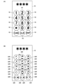
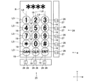
- A is a diagram showing an example of an aerial image displayed in the aerial image display area shown in FIG. 1, and
- B is for explaining a display area and a recognition area of an image of a button shown in (A). It is a figure of.
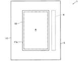
- FIG. 1 is a schematic diagram for explaining the configuration of the input device 1 according to the first embodiment of the present invention.
- FIG. 2 is a block diagram for explaining the configuration of the input device 1 shown in FIG.
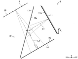
- FIG. 3 is a schematic diagram for explaining the configuration of the aerial image display device 3 used in the input device 1 shown in FIG. 4A is a diagram showing an example of an aerial image displayed in the aerial image display area R shown in FIG. 1, and
- FIG. 4B is a display of an image of the button 19 shown in FIG. 4A. It is a figure for demonstrating the area DR and the recognition area KR.
- the input device 1 of the present embodiment is a device for inputting information using a user's fingertip, for example, an ATM, an authentication device at the time of payment of a credit card, an automatic ticket issuing machine, a vending machine, or an entry / exit. Used in management equipment.
- a personal identification number is input.
- the input device 1 is an aerial image display device 3 that displays an aerial image in a three-dimensional space, and an optical detection for detecting the position of a user's fingertip in the aerial image display area R that is an area where the aerial image is displayed. It includes a mechanism 4, an aerial image display device 3, and a housing 5 in which the detection mechanism 4 is housed. Further, the input device 1 includes a control unit 8 for controlling the input device 1.
- the aerial image display device 3 includes a display mechanism 11 having a display surface 11a for displaying an image, and an aerial imaging mechanism 12 for forming an image as an aerial image by projecting an image displayed on the display surface 11a into space. ing.
- the display mechanism 11 and the aerial imaging mechanism 12 are housed in the housing 5.
- the aerial imaging mechanism 12 includes a beam splitter 13 and a retroreflective material 14.
- the Y direction in FIG. 3 which is orthogonal to the vertical direction (vertical direction), is the left-right direction, and the direction orthogonal to the up-down direction and the left-right direction is the front-back direction.
- a user standing on the front side of the input device 1 performs a predetermined operation on the front side of the input device 1.
- the display mechanism 11 is, for example, a liquid crystal display or an organic EL display, and the display surface 11a is a screen of the display.
- the display surface 11a faces diagonally forward and downward.
- the beam splitter 13 is formed in a flat plate shape.
- the beam splitter 13 is arranged on the front side of the display mechanism 11.
- the beam splitter 13 reflects a part of the light emitted from the display surface 11a. That is, one surface of the beam splitter 13 is a reflecting surface 13a that reflects a part of the light emitted from the display surface 11a.
- the reflective surface 13a faces diagonally backward and downward.
- the retroreflective material 14 is formed in a flat plate shape.
- the retroreflective material 14 is arranged below the display mechanism 11 and behind the beam splitter 13.
- the light reflected by the beam splitter 13 is incident on the retroreflective material 14.
- the retroreflective material 14 reflects the incident light toward the beam splitter 13 in the same direction as the incident direction. That is, one surface of the retroreflective material 14 is a retroreflective surface 14a on which the light reflected by the beam splitter 13 is incident and the incident light is reflected toward the beam splitter 13 in the same direction as the incident direction. ..
- a 1/4 wave plate is attached to the retroreflective surface 14a.
- the retroreflective surface 14a faces diagonally forward and upward.
- a part of the light emitted from the display surface 11a of the display mechanism 11 is reflected by the reflection surface 13a of the beam splitter 13 and is incident on the retroreflective surface 14a of the retroreflective material 14.
- the light reflected by the reflecting surface 13a heads diagonally backward and downward.
- the light incident on the retroreflective surface 14a is reflected in the same direction as the light incident on the retroreflective surface 14a.
- the light reflected by the retroreflective surface 14a goes diagonally forward and upward and passes through the beam splitter 13.
- the optical axis L1 of the light emitted from the display surface 11a and the optical axis L2 of the light reflected by the beam splitter 13 are orthogonal to each other. Further, the optical axis of the light reflected by the retroreflective material 14 coincides with the optical axis L2.
- An aerial image is formed in the aerial image display area R by the light transmitted through the beam splitter 13.
- the aerial image display area R is arranged on the diagonally front upper side of the beam splitter 13.
- the aerial image formed in the aerial image display area R is recognized by the user standing on the front side of the input device 1 as an image tilted toward the lower side toward the front side.
- the housing 5 is formed in the shape of a rectangular parallelepiped box, for example.
- the housing 5 includes a frame body 17 that surrounds the aerial image display area R.
- the frame body 17 is formed in a rectangular or square frame shape and also in a flat plate shape.
- the frame body 17 constitutes the front upper surface of the housing 5.
- the frame body 17 formed in a flat plate shape is inclined toward the lower side toward the front side.
- the inner peripheral side of the frame body 17 is an opening 17a leading to the inside of the housing 5.
- the opening 17a is formed in a rectangular shape or a square shape.
- the aerial image display area R is formed in the opening 17a.
- the aerial image display area R is an input unit 18 for the user to input information using a fingertip. In this embodiment, the personal identification number is input in the input unit 18.
- the detection mechanism 4 detects the position of the user's fingertip in the aerial image display area R. That is, the input unit 18 is included in the detection range of the detection mechanism 4.
- the detection mechanism 4 is a reflection type sensor array. Specifically, the detection mechanism 4 is a reflection type including a plurality of light emitting units that emit infrared light and a plurality of light receiving units that are emitted from the light emitting unit and reflected by the user's fingertip. It is an infrared sensor array. Further, the detection mechanism 4 is a line sensor in which light emitting portions and light receiving portions are alternately and linearly arranged. The detection mechanism 4 is arranged on the side of the opening 17a.
- the detection mechanism 4 detects the position of the user's fingertip on the plane including the aerial image (that is, the plane including the input unit 18). Further, the detection mechanism 4 detects the position of the user's fingertip in the entire area of the aerial image display area R (that is, in the entire area of the input unit 18).
- the display mechanism 11 displays the image of the keypad for inputting the personal identification number on the display surface 11a, and the aerial imaging mechanism 12 is displayed on the display surface 11a.
- the image of the keypad is displayed as an aerial image in the aerial image display area R (see FIG. 4A). That is, the aerial image displayed in the aerial image display area R when the password is input is an image of the keypad.
- the image of the keypad which is an aerial image, includes images of a plurality of buttons 19 for specifying information (that is, a personal identification number) input by the input unit 18.
- the images of the plurality of buttons 19 include images of the buttons 19 having a plurality of numbers. Specifically, the images of the plurality of buttons 19 include images of the buttons 19 having 10 numbers from “0" to "9". Further, the images of the plurality of buttons 19 include images of the five buttons 19 other than the numbers.
- the images of the plurality of buttons 19 are arranged in a matrix. Specifically, the images of the 15 buttons 19 are arranged in a matrix of 5 rows and 3 columns.
- the user inputs the password using the image of the keypad displayed in the aerial image display area R. Specifically, the user inputs the password by sequentially moving the fingertip to the position of the image of the button 19 having a predetermined number displayed in the aerial image display area R. That is, the user inputs the password by sequentially performing an operation (pointing operation) of pointing the image of the button 19 having a predetermined number with the fingertip in the input unit 18.
- the control unit 8 recognizes the image of the numerical button 19 inserted by the pointing operation based on the detection result of the detection mechanism 4 (that is, the detection result of the position of the fingertip of the user). It is an area in the display area DR of the image of the button 19 displayed in the aerial image display area R, and the image of the predetermined button 19 is inserted by the fingertip of the user based on the detection result of the detection mechanism 4. Assuming that the area recognized by the control unit 8 is the recognition area KR, in this embodiment, the recognition area KR is narrower than the display area DR (see FIG. 4B).
- the control unit 8 has an image of a predetermined button 19 based on the detection result of the detection mechanism 4. Is recognized as being inserted.
- the entire image of the button 19 surrounded by a solid circle (circle) is the display area DR
- the area surrounded by the broken line circle (circle) in the image of the button 19 is the recognition area KR.
- the central portion of the display area DR is the recognition area KR.
- control unit 8 When the control unit 8 recognizes that the image of the button 19 having a predetermined number has been inserted by the pointing operation based on the detection result of the detection mechanism 4, it sends a control command to the display mechanism 11 and displays the display mechanism 11. Displays, for example, an image marked with "*" on the upper portion of the image of the plurality of buttons 19 on the display surface 11a, and the aerial imaging mechanism 12 displays the image marked with "*" displayed on the display surface 11a. Is displayed in the aerial image display area R as an aerial image (see FIG. 4).
- the aerial image display area R is an input unit 18 for inputting a personal identification number, and the aerial image is used to specify the personal identification number input by the input unit 18. Contains images of a plurality of buttons 19 of. Further, in the present embodiment, the recognition area KR is narrower than the display area DR of the image of the button 19, and the control unit 8 inserts the recognition area KR narrower than the display area DR when the user inserts it. It is recognized that the image of the button 19 is inserted based on the detection result of the detection mechanism 4.
- the control unit 8 does not recognize that the image of the predetermined button 19 is inserted. That is, in the present embodiment, it is possible to make the control unit 8 recognize that the image of the predetermined button 19 is inserted by the user only when the image of the button 19 intended by the user is surely inserted. Therefore, in the input device 1 of the present embodiment, it is possible to suppress an input error of the personal identification number.
- the image of the predetermined button 19 is inserted by the user only when the image of the button 19 intended by the user is surely inserted. This makes it easier for the control unit 8 to recognize this. Therefore, in the input device 1 of the present embodiment, it is possible to effectively suppress the input error of the personal identification number.
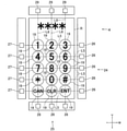
- FIG. 5 is a schematic diagram for explaining the configuration of the input device 1 according to the second embodiment of the present invention.
- the same reference numerals are given to the same configurations as those in the first embodiment.
- the configuration of the detection mechanism 4 is different between the first embodiment and the second embodiment. Further, since the configuration of the detection mechanism 4 is different between the first embodiment and the second embodiment, the recognition method when the control unit 8 recognizes that the image of the predetermined button 19 is inserted by the user is different. do.
- the configuration of the input device 1 according to the second embodiment will be described with a focus on the differences from the first embodiment.
- the image of the keypad is displayed as an aerial image in the aerial image display area R.
- the images of the 15 buttons 19 are arranged in a matrix of 5 rows and 3 columns.
- the vertical direction (row direction, V direction in FIG. 5) of the images of the plurality of buttons 19 arranged in a matrix is the first.
- the lateral direction (column direction, W direction in FIG. 5) of the images of the plurality of buttons 19 arranged in a matrix is defined as the second direction.
- the first direction and the second direction are orthogonal to each other.
- the detection mechanism 4 includes a first detection mechanism 24 for detecting the position of the user's fingertip in the first direction when each of the plurality of buttons 19 is pointed by the user's fingertip, and a second direction of the user's fingertip. It is provided with a second detection mechanism 25 for detecting.
- the detection mechanism 4 of this embodiment is composed of a first detection mechanism 24 and a second detection mechanism 25.
- the first detection mechanism 24 is a transmissive sensor having a plurality of light emitting units 26 and a plurality of light receiving units 27.
- the second detection mechanism 25 is a transmissive sensor having a plurality of light emitting units 28 and a plurality of light receiving units 29.
- the light emitting units 26 and 28 emit infrared light, and the light receiving units 27 and 29 are incident with the infrared light emitted from the light emitting units 26 and 28. That is, the first detection mechanism 24 and the second detection mechanism 25 are transmissive infrared sensors.
- the first detection mechanism 24 includes a light emitting unit 26 and a light receiving unit 27 having the same number of rows as the number of rows of 15 buttons 19 arranged in a matrix. That is, the first detection mechanism 24 includes five light emitting units 26 and five light receiving units 27. That is, the first detection mechanism 24 includes five pairs of light emitting units 26 and light receiving units 27.
- the five light emitting units 26 are arranged in the first direction at a constant pitch, and the five light receiving units 27 are arranged in the first direction at a constant pitch.
- the paired light emitting unit 26 and the light receiving unit 27 are arranged at the same position in the first direction. Further, the light emitting unit 26 and the light receiving unit 27 that form a pair are arranged to face each other so as to sandwich the aerial image display region R (that is, to sandwich the input unit 18) in the second direction.
- the second detection mechanism 25 includes a light emitting unit 28 and a light receiving unit 29 having the same number of rows as the number of rows of 15 buttons 19 arranged in a matrix. That is, the second detection mechanism 25 includes three light emitting units 28 and three light receiving units 29. That is, the second detection mechanism 25 includes three pairs of light emitting units 28 and light receiving units 29.
- the three light emitting units 28 are arranged in the second direction at a constant pitch, and the three light receiving units 29 are arranged in the second direction at a constant pitch.
- the light emitting unit 28 and the light receiving unit 29 that form a pair are arranged at the same position in the second direction. Further, the light emitting unit 28 and the light receiving unit 29 that form a pair are arranged to face each other so as to sandwich the aerial image display region R (that is, to sandwich the input unit 18) in the first direction.
- the arrangement pitch of the light emitting unit 26 in the first direction is equal to the arrangement pitch of the images of the plurality of buttons 19 displayed in the aerial image display area R in the first direction.
- the optical axis L5 of the light (specifically, infrared light) emitted from the light emitting unit 26 passes through the center of the image of the button 19 displayed in the aerial image display area R. More specifically, the optical axis L5 passes through the center of the image of the button 19 displayed in the aerial image display area R when viewed from a direction orthogonal to the plane including the aerial image.
- the arrangement pitch of the light emitting unit 28 in the second direction is equal to the arrangement pitch of the images of the plurality of buttons 19 displayed in the aerial image display area R in the second direction.
- the optical axis L6 of the light (specifically, infrared light) emitted from the light emitting unit 28 passes through the center of the image of the button 19 displayed in the aerial image display area R. More specifically, the optical axis L6 passes through the center of the image of the button 19 displayed in the aerial image display area R when viewed from a direction orthogonal to the plane including the aerial image.
- the control unit 8 recognizes the image of the numerical button 19 inserted by the pointing operation based on the detection result of the first detection mechanism 24 and the detection result of the second detection mechanism 25.
- the detection mechanism 4 is the first for detecting the position of the user's fingertip in the first direction when each of the images of the plurality of buttons 19 is inserted by the user's fingertip.
- a detection mechanism 24 and a second detection mechanism 25 for detecting the position of the user's fingertip in the second direction are provided, and the control unit 8 includes the detection result of the first detection mechanism 24 and the second detection mechanism 25. Based on the detection result, the image of the numerical button 19 inserted by the pointing operation is recognized.
- the user's fingertip is based on the detection result of the first detection mechanism 24 and the detection result of the second detection mechanism 25 (that is, based on the detection result of the position of the user's fingertip in two directions). Only when the intended image of the button 19 is surely inserted, the control unit 8 can be made to recognize that the image of the predetermined button 19 is inserted by the fingertip of the user. Therefore, in the input device 1 of the present embodiment, it is possible to suppress an input error of the personal identification number as in the first embodiment.
- the first detection mechanism 24 and the second detection mechanism 25 are transmissive sensors having a plurality of light emitting units 26 and 28 and a plurality of light receiving units 27 and 29. Therefore, in this embodiment, as compared with the case where the first detection mechanism 24 and the second detection mechanism 25 are reflection type sensors, it is based on the detection result of the first detection mechanism 24 and the detection result of the second detection mechanism 25. Therefore, it becomes possible to more accurately specify the position of the fingertip when the user's fingertip points to the image of the predetermined button 19 in the input unit 18.
- the user's fingertip is only when the image of the button 19 intended by the user's fingertip is reliably inserted based on the detection result of the first detection mechanism 24 and the detection result of the second detection mechanism 25. This makes it easier for the control unit 8 to recognize that the image of the predetermined button 19 has been inserted. Therefore, in the input device 1 of the present embodiment, it is possible to effectively suppress the input error of the personal identification number.
- the optical axes L5 and L6 of the light emitted from the light emitting units 26 and 28 pass through the center of the image of the button 19 displayed in the aerial image display area R. Therefore, in this embodiment, the user's fingertip is only when the image of the button 19 intended by the user's fingertip is surely inserted based on the detection result of the first detection mechanism 24 and the detection result of the second detection mechanism 25. It becomes easier for the input device to recognize that the image of the predetermined button 19 has been inserted. Therefore, in the input device 1 of the present embodiment, it is possible to more effectively suppress the input error of the personal identification number.
- FIG. 6 is a schematic diagram for explaining the configuration of the detection mechanism 4 according to the modified example of the second embodiment.
- the same reference numerals are given to the same configurations as those described above.
- the first detection mechanism 24 may be a reflection type infrared sensor having a plurality of light emitting units 26 and a plurality of light receiving units 27.
- the second detection mechanism 25 may be a reflection type infrared sensor having a plurality of light emitting units 28 and a plurality of light receiving units 29.
- the first detection mechanism 24 includes a light emitting unit 26 and a light receiving unit 27 having the same number of rows as the number of rows of the 15 buttons 19 arranged in a matrix
- the second detection mechanism 25 has a matrix. It includes the same number of light emitting units 28 and light receiving units 29 as the number of rows of 15 buttons 19 arranged.
- the arrangement pitch of the light emitting unit 26 in the first direction is equal to the arrangement pitch of the images of the plurality of buttons 19 displayed in the aerial image display area R in the first direction, and is emitted from the light emitting unit 26.
- the optical axis L5 of the light that is generated passes through the center of the image of the button 19 displayed in the aerial image display area R.
- the arrangement pitch of the light emitting unit 28 in the second direction is equal to the arrangement pitch of the images of the plurality of buttons 19 displayed in the aerial image display area R in the second direction, and the light emitted from the light emitting unit 28.
- the optical axis L6 of the above passes through the center of the image of the button 19 displayed in the aerial image display area R.
- the control unit 8 recognizes the image of the numerical button 19 inserted by the pointing operation based on the detection result of the first detection mechanism 24 and the detection result of the second detection mechanism 25.
- the user's fingertip only when the image of the button 19 intended by the user's fingertip is surely inserted based on the detection result of the first detection mechanism 24 and the detection result of the second detection mechanism 25. Since it is possible to make the control unit 8 recognize that the image of the predetermined button 19 has been inserted, it is possible to suppress an input error of the password.
- the portion of the display area DR deviated from the center may be the recognition area KR.
- the recognition area KR is a circular area, but the recognition area KR may be a non-circular area such as an elliptical area or a polygonal area.
- the optical axis L5 of the light emitted from the light emitting unit 26 may pass through a position deviated from the center of the image of the button 19 displayed in the aerial image display area R, or the light emitting unit.
- the optical axis L6 of the light emitted from the 28 may pass through a position deviated from the center of the image of the button 19 displayed in the aerial image display area R.
- the first direction and the second direction are orthogonal to each other, but the first direction and the second direction may not be orthogonal to each other.
- the first detection mechanism 24 and the second detection mechanism 25 may be a transmission type sensor array.
- the image of the keypad displayed in the aerial image display area R may be composed of, for example, images of 12 buttons 19 arranged in 4 rows and 3 columns. Further, in the above-described form, information other than the personal identification number may be input by the input device 1.
- the aerial image displayed in the aerial image display area R may be an image other than the keypad. Even in this case, the aerial image includes an image of a button for specifying information input by the input unit 18.
- 1 input device, 4 detection mechanism, 8 control unit 11 display mechanism, 11a display surface, 12 aerial imaging mechanism, 18 input unit, 19 button, 24 1st detection mechanism, 25 2nd detection mechanism, 26, 28 light emitting unit , 27, 29 light receiving part, DR display area, KR recognition area, L5, L6 optical axis of light emitted from the light emitting part, R aerial image display area, V 1st direction, W 2nd direction
Landscapes
- Engineering & Computer Science (AREA)
- Theoretical Computer Science (AREA)
- Physics & Mathematics (AREA)
- General Engineering & Computer Science (AREA)
- General Physics & Mathematics (AREA)
- Computer Hardware Design (AREA)
- Health & Medical Sciences (AREA)
- General Health & Medical Sciences (AREA)
- Human Computer Interaction (AREA)
- Software Systems (AREA)
- Bioethics (AREA)
- Computer Security & Cryptography (AREA)
- Medical Informatics (AREA)
- Databases & Information Systems (AREA)
- Optics & Photonics (AREA)
- Oral & Maxillofacial Surgery (AREA)
- Multimedia (AREA)
- User Interface Of Digital Computer (AREA)
- Position Input By Displaying (AREA)
- Input From Keyboards Or The Like (AREA)
- Image Input (AREA)
Priority Applications (2)
| Application Number | Priority Date | Filing Date | Title |
|---|---|---|---|
| JP2022538616A JPWO2022018972A1 (enExample) | 2020-07-22 | 2021-05-31 | |
| US18/016,925 US20240036678A1 (en) | 2020-07-22 | 2021-05-31 | Input device and input device control method |
Applications Claiming Priority (2)
| Application Number | Priority Date | Filing Date | Title |
|---|---|---|---|
| US202063054799P | 2020-07-22 | 2020-07-22 | |
| US63/054,799 | 2020-07-22 |
Publications (1)
| Publication Number | Publication Date |
|---|---|
| WO2022018972A1 true WO2022018972A1 (ja) | 2022-01-27 |
Family
ID=79728618
Family Applications (4)
| Application Number | Title | Priority Date | Filing Date |
|---|---|---|---|
| PCT/JP2021/020743 Ceased WO2022018972A1 (ja) | 2020-07-22 | 2021-05-31 | 入力装置および入力装置の制御方法 |
| PCT/JP2021/020744 Ceased WO2022018973A1 (ja) | 2020-07-22 | 2021-05-31 | 入力装置および情報処理装置 |
| PCT/JP2021/020742 Ceased WO2022018971A1 (ja) | 2020-07-22 | 2021-05-31 | 入力装置および入力装置の制御方法 |
| PCT/JP2021/027020 Ceased WO2022019279A1 (ja) | 2020-07-22 | 2021-07-19 | 入力装置 |
Family Applications After (3)
| Application Number | Title | Priority Date | Filing Date |
|---|---|---|---|
| PCT/JP2021/020744 Ceased WO2022018973A1 (ja) | 2020-07-22 | 2021-05-31 | 入力装置および情報処理装置 |
| PCT/JP2021/020742 Ceased WO2022018971A1 (ja) | 2020-07-22 | 2021-05-31 | 入力装置および入力装置の制御方法 |
| PCT/JP2021/027020 Ceased WO2022019279A1 (ja) | 2020-07-22 | 2021-07-19 | 入力装置 |
Country Status (3)
| Country | Link |
|---|---|
| US (3) | US20240036678A1 (enExample) |
| JP (4) | JPWO2022018973A1 (enExample) |
| WO (4) | WO2022018972A1 (enExample) |
Cited By (1)
| Publication number | Priority date | Publication date | Assignee | Title |
|---|---|---|---|---|
| JP2023007394A (ja) * | 2021-06-28 | 2023-01-18 | 日立チャネルソリューションズ株式会社 | 情報処理システム |
Families Citing this family (1)
| Publication number | Priority date | Publication date | Assignee | Title |
|---|---|---|---|---|
| JP2023131250A (ja) | 2022-03-09 | 2023-09-22 | アルプスアルパイン株式会社 | 光学素子の製造方法、光学素子、空中映像表示装置および空間入力装置 |
Citations (6)
| Publication number | Priority date | Publication date | Assignee | Title |
|---|---|---|---|---|
| JPH07210299A (ja) * | 1994-01-20 | 1995-08-11 | Sumitomo Wiring Syst Ltd | 光学式入力装置の入力位置検出方法 |
| JP2000181632A (ja) * | 1998-12-17 | 2000-06-30 | Funai Electric Co Ltd | 映像機器のタッチ入力装置 |
| WO2012032842A1 (ja) * | 2010-09-06 | 2012-03-15 | シャープ株式会社 | 表示システム、および検出方法 |
| JP2016006566A (ja) * | 2014-06-20 | 2016-01-14 | 船井電機株式会社 | 入力装置 |
| JP2017107165A (ja) * | 2015-12-07 | 2017-06-15 | 国立大学法人宇都宮大学 | 表示装置及び空中像の表示方法 |
| JP2020067838A (ja) * | 2018-10-25 | 2020-04-30 | 日立オムロンターミナルソリューションズ株式会社 | 入出力装置及び自動取引装置 |
Family Cites Families (23)
| Publication number | Priority date | Publication date | Assignee | Title |
|---|---|---|---|---|
| US5949348A (en) * | 1992-08-17 | 1999-09-07 | Ncr Corporation | Method and apparatus for variable keyboard display |
| JP2002236944A (ja) * | 2001-02-08 | 2002-08-23 | Hitachi Ltd | 情報提供端末 |
| JP4064647B2 (ja) * | 2001-08-24 | 2008-03-19 | 富士通株式会社 | 情報処理装置及び入力操作装置 |
| JP2004178584A (ja) * | 2002-11-26 | 2004-06-24 | Asulab Sa | 機能、装置、又は所定の場所にアクセスするためのタッチスクリーンによるセキュリティコードの入力方法、及びその方法を実行するためのデバイス |
| WO2012030153A2 (ko) * | 2010-09-02 | 2012-03-08 | 주식회사 엘앤와이비젼 | 비접촉식 입력장치 |
| JP5602668B2 (ja) * | 2011-03-24 | 2014-10-08 | 日本電産サンキョー株式会社 | 媒体処理装置およびフレキシブルケーブル |
| US8978975B2 (en) * | 2011-07-18 | 2015-03-17 | Accullink, Inc. | Systems and methods for authenticating near field communcation financial transactions |
| US20130301830A1 (en) * | 2012-05-08 | 2013-11-14 | Hagai Bar-El | Device, system, and method of secure entry and handling of passwords |
| CA2917478A1 (en) * | 2013-07-10 | 2015-01-15 | Real View Imaging Ltd. | Three dimensional user interface |
| JP2015060296A (ja) * | 2013-09-17 | 2015-03-30 | 船井電機株式会社 | 空間座標特定装置 |
| US9531689B1 (en) * | 2014-11-10 | 2016-12-27 | The United States Of America As Represented By The Secretary Of The Navy | System and method for encryption of network data |
| US12061742B2 (en) * | 2016-06-28 | 2024-08-13 | Nikon Corporation | Display device and control device |
| US11635827B2 (en) * | 2016-06-28 | 2023-04-25 | Nikon Corporation | Control device, display device, program, and detection method |
| WO2018003860A1 (ja) * | 2016-06-28 | 2018-01-04 | 株式会社ニコン | 表示装置、プログラム、表示方法および制御装置 |
| JP6725371B2 (ja) * | 2016-09-07 | 2020-07-15 | シャープ株式会社 | 表示装置、表示システム、および表示方法 |
| EP3319069B1 (en) * | 2016-11-02 | 2019-05-01 | Skeyecode | Method for authenticating a user by means of a non-secure terminal |
| JP6913494B2 (ja) * | 2017-03-30 | 2021-08-04 | 日本電産サンキョー株式会社 | フレキシブルプリント基板およびカードリーダ |
| JP6974032B2 (ja) * | 2017-05-24 | 2021-12-01 | シャープ株式会社 | 画像表示装置、画像形成装置、制御プログラムおよび制御方法 |
| JP2019109636A (ja) * | 2017-12-18 | 2019-07-04 | コニカミノルタ株式会社 | 非接触入力装置 |
| JP2019133284A (ja) * | 2018-01-30 | 2019-08-08 | コニカミノルタ株式会社 | 非接触式入力装置 |
| JP7164405B2 (ja) * | 2018-11-07 | 2022-11-01 | 日立チャネルソリューションズ株式会社 | 画像読取り装置及び方法 |
| JP7173895B2 (ja) | 2019-02-22 | 2022-11-16 | 日立チャネルソリューションズ株式会社 | 空中像表示装置、取引装置、および空中像表示装置における空中像結像制御方法 |
| JP7251301B2 (ja) * | 2019-05-10 | 2023-04-04 | 京セラドキュメントソリューションズ株式会社 | 画像処理システム、画像処理方法、及び画像形成装置 |
-
2021
- 2021-05-31 WO PCT/JP2021/020743 patent/WO2022018972A1/ja not_active Ceased
- 2021-05-31 WO PCT/JP2021/020744 patent/WO2022018973A1/ja not_active Ceased
- 2021-05-31 US US18/016,925 patent/US20240036678A1/en not_active Abandoned
- 2021-05-31 US US18/016,927 patent/US12001031B2/en active Active
- 2021-05-31 JP JP2022538617A patent/JPWO2022018973A1/ja active Pending
- 2021-05-31 WO PCT/JP2021/020742 patent/WO2022018971A1/ja not_active Ceased
- 2021-05-31 JP JP2022538616A patent/JPWO2022018972A1/ja not_active Withdrawn
- 2021-05-31 JP JP2022538615A patent/JPWO2022018971A1/ja active Pending
- 2021-07-19 US US18/016,785 patent/US20230288723A1/en active Pending
- 2021-07-19 JP JP2022538006A patent/JPWO2022019279A1/ja active Pending
- 2021-07-19 WO PCT/JP2021/027020 patent/WO2022019279A1/ja not_active Ceased
Patent Citations (6)
| Publication number | Priority date | Publication date | Assignee | Title |
|---|---|---|---|---|
| JPH07210299A (ja) * | 1994-01-20 | 1995-08-11 | Sumitomo Wiring Syst Ltd | 光学式入力装置の入力位置検出方法 |
| JP2000181632A (ja) * | 1998-12-17 | 2000-06-30 | Funai Electric Co Ltd | 映像機器のタッチ入力装置 |
| WO2012032842A1 (ja) * | 2010-09-06 | 2012-03-15 | シャープ株式会社 | 表示システム、および検出方法 |
| JP2016006566A (ja) * | 2014-06-20 | 2016-01-14 | 船井電機株式会社 | 入力装置 |
| JP2017107165A (ja) * | 2015-12-07 | 2017-06-15 | 国立大学法人宇都宮大学 | 表示装置及び空中像の表示方法 |
| JP2020067838A (ja) * | 2018-10-25 | 2020-04-30 | 日立オムロンターミナルソリューションズ株式会社 | 入出力装置及び自動取引装置 |
Cited By (2)
| Publication number | Priority date | Publication date | Assignee | Title |
|---|---|---|---|---|
| JP2023007394A (ja) * | 2021-06-28 | 2023-01-18 | 日立チャネルソリューションズ株式会社 | 情報処理システム |
| JP7402265B2 (ja) | 2021-06-28 | 2023-12-20 | 日立チャネルソリューションズ株式会社 | 情報処理システム |
Also Published As
| Publication number | Publication date |
|---|---|
| WO2022019279A1 (ja) | 2022-01-27 |
| US20230351804A1 (en) | 2023-11-02 |
| US20240036678A1 (en) | 2024-02-01 |
| US12001031B2 (en) | 2024-06-04 |
| WO2022018971A1 (ja) | 2022-01-27 |
| JPWO2022018972A1 (enExample) | 2022-01-27 |
| JPWO2022018973A1 (enExample) | 2022-01-27 |
| WO2022018973A1 (ja) | 2022-01-27 |
| JPWO2022019279A1 (enExample) | 2022-01-27 |
| US20230288723A1 (en) | 2023-09-14 |
| JPWO2022018971A1 (enExample) | 2022-01-27 |
Similar Documents
| Publication | Publication Date | Title |
|---|---|---|
| CN107077003B (zh) | 光学器件 | |
| CN108121483B (zh) | 嵌入有光学成像传感器的平板显示器 | |
| US8482557B2 (en) | Device and method for setting instructed position during three-dimensional display, as well as program | |
| US8248666B2 (en) | Information input/output device including a stage surface on which a reflecting medium including a printed dot pattern is disposed | |
| US11048900B2 (en) | Image reading device and method | |
| US6175679B1 (en) | Optical keyboard | |
| EP3153322A1 (en) | Print position correction | |
| US8299980B2 (en) | Image display device | |
| US6948820B2 (en) | Interactive display system having an optical channeling element | |
| US9298255B2 (en) | Transmissive display apparatus and operation input method | |
| JP5012781B2 (ja) | ヘッドマウントディスプレイ | |
| EP4095589B1 (en) | Display device | |
| JP2006004300A (ja) | 入出力装置及び端末装置 | |
| WO2022019280A1 (ja) | 入力装置および入力装置の制御方法 | |
| WO2022018972A1 (ja) | 入力装置および入力装置の制御方法 | |
| WO2012153499A1 (ja) | 表示装置、表示方法、集積回路、プログラム | |
| JP2018206149A (ja) | 入力装置 | |
| CN109313348B (zh) | 光学器件及光学系统 | |
| US10429942B2 (en) | Gesture input device | |
| US20050239525A1 (en) | Gaming machine | |
| US20050195127A1 (en) | Image display system | |
| CN111597912A (zh) | 显示模组及具有该显示模组的电子设备 | |
| EP4293637B1 (en) | Biometric authentication device | |
| EP4134730B1 (en) | Display device and spatial input device including the same | |
| US20050192093A1 (en) | Gaming machine |
Legal Events
| Date | Code | Title | Description |
|---|---|---|---|
| 121 | Ep: the epo has been informed by wipo that ep was designated in this application |
Ref document number: 21846611 Country of ref document: EP Kind code of ref document: A1 |
|
| ENP | Entry into the national phase |
Ref document number: 2022538616 Country of ref document: JP Kind code of ref document: A |
|
| WWE | Wipo information: entry into national phase |
Ref document number: 18016925 Country of ref document: US |
|
| NENP | Non-entry into the national phase |
Ref country code: DE |
|
| 122 | Ep: pct application non-entry in european phase |
Ref document number: 21846611 Country of ref document: EP Kind code of ref document: A1 |