WO2022018894A1 - 内視鏡システム及びその作動方法 - Google Patents
内視鏡システム及びその作動方法 Download PDFInfo
- Publication number
- WO2022018894A1 WO2022018894A1 PCT/JP2021/004825 JP2021004825W WO2022018894A1 WO 2022018894 A1 WO2022018894 A1 WO 2022018894A1 JP 2021004825 W JP2021004825 W JP 2021004825W WO 2022018894 A1 WO2022018894 A1 WO 2022018894A1
- Authority
- WO
- WIPO (PCT)
- Prior art keywords
- image
- reference image
- illumination light
- light
- illumination
- Prior art date
- Legal status (The legal status is an assumption and is not a legal conclusion. Google has not performed a legal analysis and makes no representation as to the accuracy of the status listed.)
- Ceased
Links
Images


Classifications
-
- A—HUMAN NECESSITIES
- A61—MEDICAL OR VETERINARY SCIENCE; HYGIENE
- A61B—DIAGNOSIS; SURGERY; IDENTIFICATION
- A61B1/00—Instruments for performing medical examinations of the interior of cavities or tubes of the body by visual or photographical inspection, e.g. endoscopes; Illuminating arrangements therefor
- A61B1/04—Instruments for performing medical examinations of the interior of cavities or tubes of the body by visual or photographical inspection, e.g. endoscopes; Illuminating arrangements therefor combined with photographic or television appliances
- A61B1/045—Control thereof
-
- G—PHYSICS
- G02—OPTICS
- G02B—OPTICAL ELEMENTS, SYSTEMS OR APPARATUS
- G02B23/00—Telescopes, e.g. binoculars; Periscopes; Instruments for viewing the inside of hollow bodies; Viewfinders; Optical aiming or sighting devices
- G02B23/24—Instruments or systems for viewing the inside of hollow bodies, e.g. fibrescopes
Definitions
- the present invention relates to an endoscopic system that displays an inspection image and a reference image having a high degree of similarity to the inspection image among the diagnosed reference images, and an operation method thereof.
- image diagnosis such as diagnosis of a patient's medical condition and follow-up is performed using endoscopic images and the like. Based on such diagnostic imaging, doctors and others make decisions on treatment policies.
- the person who performs the image diagnosis such as a doctor is inexperienced, or if the image to be diagnosed is a rare case even if he / she has experience, and the image is out of the field of specialization, the doctor diagnoses it. May be difficult to do reliably.
- Patent Document 1 a first medical image obtained by imaging an observation target with an imaging unit is compared with a second medical image stored in a database, and a second image feature having a high degree of similarity is compared.
- the medical images of the above are searched, and the searched second medical images are displayed side by side on the display device.
- the white light and multiple types of special light As described above, if the operation of switching each time during the inspection is performed, it will impose a burden on the user. Therefore, the white light and multiple types of special light, etc. It is preferable to automatically switch a plurality of illumination lights of the above to illuminate a lesion or the like, and provide a white light image based on the white light and a special light image based on a plurality of types of special light as an inspection image.
- a plurality of types of inspection images are acquired by automatic lighting switching of illumination light in this way, and each inspection image and a reference image for comparison with each inspection image are displayed together. Is not listed.
- the present invention provides a plurality of types of inspection images based on a plurality of types of illumination light and a reference image for comparing each inspection image without imposing a burden on the user by switching the illumination of a plurality of types of illumination light. It is an object of the present invention to provide an endoscopic system that can be displayed on a display and a method of operating the same.
- the endoscope system of the present invention includes a light source unit and an image control processor.
- the light source unit emits first illumination light and second illumination light having different emission spectra from each other.
- the light source unit automatically switches between the first lighting period for emitting the first illumination light and the second illumination period for emitting the second illumination light, the light source unit emits the first illumination light in the first emission pattern, and the first emission pattern is used. 2 Illumination light is emitted in the second emission pattern.
- the image control processor captures the first illumination light image captured by irradiating the subject with the first illumination light, the second illumination light image captured by irradiating the subject with the second illumination light, and the second illumination light image.
- At least one of the superimposed images obtained by superimposing and displaying the analysis result obtained by the analysis processing on the first illumination light image is acquired as an inspection image, and the inspection image and the reference image are compared based on the feature amount.
- the reference image storage memory that calculates the total similarity and stores the diagnosed reference image, and among the plurality of reference images for which the total similarity has been calculated, the reference image whose total similarity satisfies a specific condition is selected. Select and display the inspection image and the selected reference image on the display.
- the image control processor calculates the feature amount of the reference image, calculates the total similarity based on the feature amount of the inspection image and the reference image, and then sets a specific condition. It is preferable to display the satisfying reference image and the inspection image.
- the display of the reference image can be switched according to the ranking of the overall similarity.
- the image to be displayed as an inspection image is at least one of a superimposed image, a first illumination light image, and a second illumination light image, and it is preferable that the images can be switched between each other.
- the image displayed as the reference image is either a white light image or a special light image, and it is preferable that the images can be switched between each other.
- the inspection image and the reference image it is preferable to compare the feature amounts of the inspection image and the reference image between the first illumination light image and the white light image, or between the second illumination light image and the special light image. It is preferable to display a warning when a specific condition is not met. When selecting a plurality of reference images, it is preferable that specific conditions can be changed.
- the inspection image can be acquired as a still image and the still image can be saved as a reference image in the reference image storage memory. It is preferable that the still image and the diagnosis result can be associated with each other and saved in the reference image storage memory as a new diagnosed reference image.
- the image control processor calculates the feature amount of the reference image, calculates the total similarity based on the feature amount, and then sets the reference image to satisfy specific conditions. It is preferable to display the inspection image. It is preferable that the image control processor outputs the total similarity for each reference image by inputting the inspection image and the reference image stored in the reference image storage memory into the learning model for similarity output. ..
- the number of frames in the first lighting period is the same in each first lighting period, and the number of frames in the first lighting period is different in each first lighting period. It is preferably any one of the first B emission patterns.
- the second emission pattern is a second A pattern in which the number of frames in the second illumination period is the same in each second illumination period, and the emission spectrum of the second illumination light is the same in each second illumination period.
- the number of frames is different in each second illumination period, and the emission spectrum of the second illumination light is the same in each second illumination period.
- the second C pattern and the number of frames in the second illumination period are different from each other in each second illumination period, and the emission spectrum of the second illumination light is any one of the second D patterns different in each second illumination period.
- the method of operating the endoscope system of the present invention is a light source unit that emits a first illumination light and a second illumination light having different emission spectra from each other, and a first illumination period and a second illumination that emit the first illumination light.
- a light source unit that emits the first illumination light in the first emission pattern and emits the second illumination light in the second emission pattern when automatically switching between the second illumination period that emits light, and for image control.
- the image control processor irradiates the subject with the first illumination light and captures the first illumination light image, and irradiates the subject with the second illumination light and captures the image.
- At least one of the illumination light image and the superimposed image obtained by superimposing the analysis result obtained by analyzing the second illumination light image on the first illumination light image is acquired as an inspection image, and the inspection image is used.
- the inspection image is used.
- a plurality of reference images for which the total similarity has been calculated by comparing the reference image with the reference image based on the feature amount to calculate the total similarity and referring to the reference image storage memory for storing the diagnosed reference image.
- a reference image whose overall similarity satisfies a specific condition is selected, and the inspection image and the selected reference image are displayed on the display.
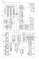
- the endoscope system 10 includes an endoscope 12, a light source device 13, a processor device 14, a display 15, and a UI (User InterFace) 16.
- the endoscope 12 is optically connected to the light source device 13 and electrically connected to the processor device 14.
- the endoscope 12 has an insertion portion 12a, an operation portion 12b, a bending portion 12c, and a tip portion 12d.
- the insertion portion 12a is inserted into the body to be observed.
- the operation portion 12b is provided at the base end portion of the insertion portion 12a.
- the curved portion 12c and the tip portion 12d are provided on the tip end side of the insertion portion 12a.
- the curved portion 12c bends by operating the angle knob 12e of the operating portion 12b.
- the tip portion 12d is directed in a desired direction by the bending motion of the bending portion 12c.
- the operation unit 12b is provided with an angle knob 12e, an observation mode changeover switch 12f, a reference image presentation switch 12g, and a zoom operation unit 12i.
- the observation mode changeover switch 12f is used for the observation mode changeover operation.
- the reference image presentation switch 12g is used for presenting the reference image.
- the still image acquisition instruction switch 12h is used for an instruction to acquire a still image to be observed.
- the zoom operation unit 12i is used to operate the zoom lens 42.
- the endoscope system 10 has three modes as observation modes: a first illumination observation mode, a second illumination observation mode, and a superimposition mode.
- the observation mode changeover switch 12f When the observation mode changeover switch 12f is pressed, the mode is switched via the image processing changeover unit 54. Further, the endoscope system 10 has two display modes, an inspection image display mode and a reference image presentation mode. When the reference image presentation switch 12g is pressed, the display mode is switched via the reference image presentation mode switching unit 56. That is, as the modes mounted on the endoscope system of the present invention, the inspection image display first illumination observation mode, the inspection image display second illumination observation mode, the inspection image display superimposition mode, the reference image presentation first illumination observation mode, and the like.
- a reference image display second illumination observation mode There are a total of six modes, a reference image display second illumination observation mode and a reference image presentation superimposition mode. From this paragraph onward, when the term "inspection image display mode” is simply used, there are three modes: inspection image display first illumination observation mode, inspection image display second illumination observation mode, and inspection image display superimposition mode. It refers to all cases, but as a default, the inspection image display superimposition mode is assumed. Further, when the term "reference image presentation mode" is simply described, all three modes of the reference image presentation first illumination observation mode, the reference image display second illumination observation mode, and the reference image presentation superimposition mode are used. However, as a default, the reference image presentation superimposition mode is assumed.
- Inspection image display In the first illumination observation mode and the reference image presentation first illumination observation mode, normal light such as white light (first illumination light) is illuminated on the observation target and imaged, so that the first illumination has a natural hue.
- the optical image is displayed on the display 15 as a display unit.
- Inspection image display In the second illumination observation mode and the reference image presentation second illumination observation mode, a specific structure is imaged by illuminating the observation target with special light (second illumination light) whose wavelength band is different from that of normal light.
- the emphasized second illumination light image is displayed on the display 15.
- the inspection image display superimposition mode and the reference image presentation superimposition mode the first illumination light and the second illumination light having different emission spectra are switched to emit light, and the image based on the first illumination light is displayed on the display 15.
- the image based on the second illumination light is subjected to analysis processing such as processing related to AI (Artificial Intelligence) and processing for obtaining feature quantities related to the observation target.
- AI Artificial Intelligence
- the result of the analysis process is superimposed and displayed on the first illumination light image.
- the similarity calculation unit 60 calculates the value of the individual feature amount and the value of the total feature amount from the inspection image.
- the total feature amount is transmitted to the attention area enhancement processing unit 111 or the display control unit 62.
- the similarity calculation unit 60 will be described later (see FIG. 15).
- the screen displayed in the three modes of the observation mode is displayed on the display 15.
- the inspection image and the reference image satisfying a specific condition are displayed as the reference image presentation screen 120.
- the processor device 14 stores the still image to be observed in the memory (not shown) in the first lighting period, the second lighting period, or both. To.
- the still image storage in the reference image presentation mode will be described in detail later.
- the processor device 14 is electrically connected to the display 15 and the UI 16.
- the display 15 outputs and displays an image to be observed, information incidental to the image to be observed, and the like.
- the UI 16 has a keyboard, a mouse, a touch pad, a microphone, and the like, and has a function of accepting input operations such as function settings.
- a reference image storage memory 80 for recording an image, image information, or the like is connected to the processor device 14 (see FIGS. 2 and 14).
- the reference image storage memory 80 may be a storage on the Web system. Further, an external memory (not shown) may be connected to the processor device 14.
- the light source device 13 includes a light source unit 20 and a light source processor 21 that controls the light source unit 20.
- the light source unit 20 has, for example, a plurality of semiconductor light sources, each of which is turned on or off, and when the light source unit 20 is turned on, the light emission amount of each semiconductor light source is controlled to emit illumination light for illuminating the observation target.
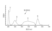
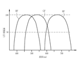
- the light source unit 20 is a V-LED (Violet Light Emitting Diode) 20a, a B-LED (Blue Light Emitting Diode) 20b, a G-LED (Green Light Emitting Diode) 20c, and an R-LED (Red Light Emitting Diode) 20d. It has 4 color LEDs.
- the V-LED generates purple light V having a center wavelength of 405 ⁇ 10 nm and a wavelength range of 380 to 420 nm.
- the B-LED generates blue light B having a center wavelength of 450 ⁇ 10 nm and a wavelength range of 420 to 500 nm.
- the G-LED produces green light G having a wavelength range of 480 to 600 nm.
- the R-LED produces red light R with a center wavelength of 620 to 630 nm and a wavelength range of 600 to 650 nm.
- the light source processor 21 controls the V-LED20a, B-LED20b, G-LED20c, and R-LED20d. By independently controlling each of the LEDs 20a to 20d, the light source processor 21 can emit purple light V, blue light B, green light G, or red light R by independently changing the amount of light. Further, the light source processor 21 emits white light having a light amount ratio of Vc: Bc: Gc: Rc among the purple light V, the blue light B, the green light G, and the red light R in the first illumination observation mode. As such, each LED 20a to 20d is controlled. In addition, Vc, Bc, Gc, Rc> 0.
- the first special light in which the light amount of the purple light V is larger than the light amounts of the other blue light B, the green light G, and the red light R may be used. ..
- a second special light in which the light amount of the green light G is larger than the light amounts of the other purple light V, the blue light B, and the red light R may be used. good.
- the light source processor 21 has a light amount ratio of Vk: Bs: Gs: purple light V, blue light B, green light G, and red light R as short-wavelength narrow-band light.
- Each LED 20a to 20d is controlled so as to emit special light that becomes Rs.
- the light amount ratio Vs: Bs: Gs: Rs is different from the light amount ratio Vc: Bc: Gc: Rc used in the first illumination observation mode, and is appropriately determined according to the observation purpose. For example, when emphasizing superficial blood vessels, it is preferable to make Vs larger than other Bs, Gs, Rs, and when emphasizing mesopelagic blood vessels, Gs is more than other Vs, Gs, Rs. It is also preferable to increase the size.
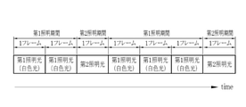
- the light source processor 21 emits the first illumination light in the first emission pattern when the first illumination light and the second illumination light are automatically switched and emitted in the superimposed mode, and the second illumination light is emitted. Is emitted in the second emission pattern.
- the first light emission pattern is the first A light emission pattern in which the number of frames in the first lighting period is the same in each first lighting period, and as shown in FIG. It is preferable that the number of frames in the first lighting period is any one of the first B emission patterns different in each first lighting period.
- the number of frames in the second illumination period is the same in each second illumination period, and the emission spectrum of the second illumination light is in each second illumination period.
- the number of frames in the second illumination period is the same in each of the second illumination periods, and the emission spectrum of the second illumination light is the same in the second illumination.
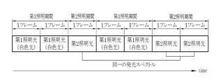
- the second B pattern differs in the period, as shown in FIG. 9, the number of frames in the second illumination period is different in each second illumination period, and the emission spectrum of the second illumination light is the first.
- the second C pattern which is the same in the two illumination periods, as shown in FIG. 10, the number of frames in the second illumination period is different in each second illumination period, and the emission spectrum of the second illumination light is different, respectively. It is preferably any one of the second D patterns that are different in the second illumination period of the above.
- the emission spectrum of the first illumination light may be the same or different in each first illumination period.
- the first lighting period is preferably longer than the second lighting period, and the first lighting period is preferably two frames or more.
- the first lighting period is set to 2 frames
- the second lighting period is set to 1 frame. Since the first illumination light is used to generate a display image to be displayed on the display 15, it is preferable to obtain a bright image by illuminating the observation target with the first illumination light.
- the first illumination light is preferably white light.
- the second illumination light is used for the analysis process, it is preferable to illuminate the observation target with the second illumination light to obtain an image suitable for the analysis process.
- purple light V, blue light B, green light G, and red light R may be used as the second illumination light.
- the second emission pattern is the second A pattern (the number of frames in the second illumination period: the same, the emission spectrum of the second illumination light: the same) or the second C pattern (the number of frames in the second illumination period: different, the second illumination).
- the second emission pattern is the second B pattern (number of frames in the second illumination period: same, emission spectrum of the second illumination light: different) or the second D pattern (number of frames in the second illumination period: different, second illumination light).
- emission spectrum different
- at least two of purple light V, blue light B, green light G, and red light R may be switched in a specific order to emit light in the second illumination period. preferable.
- FIG. 13 which will be described later, three lights, purple light V, green light G, and red light R, are sequentially emitted in that order.
- the first special light and the second special light are used as the second illumination light
- the first special light and the second special light are alternately used as the second emission pattern as the second B pattern or the second D pattern. It may be made to emit light.
- the frame refers to a unit of a period including at least a period from a specific timing to the completion of signal reading in the image pickup sensor 43.
- superficial blood vessels having a depth of 50 ⁇ m from the mucosal surface
- middle blood vessels having a depth of 200 ⁇ m from the mucosal surface
- deep blood vessels having a depth of 600 ⁇ m from the mucosal surface.
- purple light V that emphasizes surface blood vessels
- green light G that emphasizes middle layer blood vessels
- red light R that emphasizes deep blood vessels.
- the light intensity ratio includes the case where the ratio of at least one semiconductor light source is 0 (zero). Therefore, this includes the case where any one or more of the semiconductor light sources are not lit. For example, as in the case where the light amount ratio between purple light V, blue light B, green light G, and red light R is 1: 0: 0: 0, only one of the semiconductor light sources is turned on, and the other three are turned on. Even if it does not light up, it shall have a light intensity ratio.
- the light emitted by each of the LEDs 20a to 20d is incident on the light guide 23 via the optical path coupling portion 22 composed of a mirror, a lens, or the like.
- the light guide 23 is built in the endoscope 12 and a universal cord (a cord connecting the endoscope 12, the light source device 13 and the processor device 14).
- the light guide 23 propagates the light from the optical path coupling portion 22 to the tip portion 12d of the endoscope 12.
- An illumination optical system 30a and an image pickup optical system 30b are provided at the tip end portion 12d of the endoscope 12.
- the illumination optical system 30a has an illumination lens 31, and the illumination light propagated by the light guide 23 is applied to the observation target through the illumination lens 31.
- the image pickup optical system 30b has an objective lens 41 and an image pickup sensor 43. The light from the observation target due to the irradiation of the illumination light is incident on the image pickup sensor 43 via the objective lens 41 and the zoom lens 42. As a result, an image to be observed is formed on the image pickup sensor 43.
- the zoom lens 42 is a lens for enlarging the observation target, and moves between the telephoto end and the wide end by operating the zoom operation unit 12i.
- the image pickup sensor 43 is a primary color sensor, and is a B pixel (blue pixel) having a blue color filter, a G pixel (green pixel) having a green color filter, and an R pixel (red pixel) having a red color filter. It is equipped with three types of pixels.
- the blue color filter BF mainly transmits light in the blue band, specifically, light in the wavelength band having a wavelength band of 380 to 560 nm.
- the transmittance of the blue color filter BF peaks in the vicinity of the wavelength of 460 to 470 nm.
- the green color filter transmits GF, mainly light in the green band, specifically, light in the wavelength band of 460 to 620 nm.
- the red color filter RF mainly transmits light in the red band, specifically, light in the wavelength band of 580 to 760 nm.
- the image sensor 43 is preferably a CCD (Charge-Coupled Device) or a CMOS (Complementary Metal Oxide Semiconductor).
- the image pickup processor 44 controls the image pickup sensor 43. Specifically, the image signal is output from the image pickup sensor 43 by reading out the signal of the image pickup sensor 43 by the image pickup processor 44. In the first illumination observation mode, the image pickup processor 44 reads out the signal while the white light is exposed to the image pickup sensor 43, so that the Bc image signal is output from the B pixel of the image pickup sensor 43 and the Gc is output from the G pixel. The image signal is output, and the Rc image signal is output from the R pixel.
- the image pickup processor 44 reads out the signal while the special light is exposed to the image pickup sensor 43, so that the Bs image signal is output from the B pixel of the image pickup sensor 43 and the Gs is output from the G pixel.
- the image signal is output, and the Rs image signal is output from the R pixel.
- the image pickup processor 44 first reads out the signal from the image pickup sensor 43 in a state where the first illumination light is exposed to the image pickup sensor 43 during the first illumination period. Output an image signal.
- the period for outputting the first image signal is defined as the first imaging period.
- the first image signal includes a B1 image signal output from the B pixel, a G1 image signal output from the G pixel, and an R1 image signal output from the R pixel.
- the image pickup processor 44 outputs a second image signal from the image pickup sensor 43 by performing signal readout in a state where the image pickup sensor 43 is exposed to the second illumination light during the second illumination period.
- the period for outputting the second image signal is defined as the first imaging period.
- the second image signal includes a B2 image signal output from the B pixel, a G2 image signal output from the G pixel, and an R2 image signal output from the R pixel.
- the CDS / AGC (Correlated Double Sampling / Automatic Gain Control) circuit 46 performs correlated double sampling (CDS) and automatic gain control (AGC) on the analog image signal obtained from the image pickup sensor 43. ..
- CDS correlated double sampling
- AGC automatic gain control
- the image signal that has passed through the CDS / AGC circuit 45 is converted into a digital image signal by the A / D (Analog / Digital) converter 48.
- the digital image signal after A / D conversion is input to the processor device 14.
- the configuration and operation method of the processor device 14 described in the following paragraphs are common to the inspection image display mode and the reference image presentation mode with respect to the acquisition and display of the inspection image via the inspection image acquisition unit 55 and the display control unit 62. be.
- the central control unit 70 configured by the image control processor operates the program in the program memory, so that the image acquisition unit 50, the DSP (Digital Signal Processor) 52, and the noise reduction unit are operated.
- the functions of the 53, the image processing switching unit 54, the image processing unit 58, and the display control unit 62 are realized. Further, with the realization of the functions of the image processing unit 58, the functions of the first illumination light image generation unit 55a, the second illumination light image generation unit 55b, and the superimposed image generation unit 55c are realized in the inspection image acquisition unit 55. Will be done.
- the image control processor performs image processing based on the first image signal or the second image signal, and controls the display 15.
- the image acquisition unit 50 acquires a color image input from the endoscope 12.
- the color image includes a blue signal (B image signal), a green signal (G image signal), and a red signal (R image signal) output from the B pixel, the G pixel, and the R pixel of the image pickup sensor 43.
- the acquired color image is transmitted to the DSP 52.
- the DSP 52 performs various signal processing such as defect correction processing, offset processing, gain correction processing, matrix processing, gamma conversion processing, demosaic processing, and YC conversion processing on the received color image.
- the noise reduction unit 53 performs noise reduction processing by, for example, a moving average method, a median filter method, or the like on a color image that has been demosaic processed by DSP 52.
- the color image with reduced noise is input to the image processing switching unit 54.
- the image signal of each color after the gain correction processing is subjected to matrix processing to improve the color reproducibility. After that, the brightness and saturation of the color image are adjusted by the gamma conversion process.
- the color image after the matrix processing is subjected to demosaic processing (also referred to as isotropic processing and simultaneous processing), and a signal of the missing color of each pixel is generated by interpolation. By the demosaic processing, all the pixels have the signals of each color of RGB.
- the DSP 52 performs a YC conversion process on the color image after the demosaic process, and outputs the luminance signal Y, the color difference signal Cb, and the color difference signal Cr to the noise reduction unit 53.
- the color difference that expands the color difference between the normal part and the abnormal part (lesion part, etc.) included in the observation target with respect to the second image signal may be performed.
- Analysis processing may be performed on the second image signal which has undergone color difference expansion processing.
- the noise reduction unit 53 performs noise reduction processing by, for example, a moving average method, a median filter method, or the like on a color image that has been demosaic processed by DSP 52.
- the color image with reduced noise is input to the image processing switching unit 54.
- the image processing switching unit 54 sets the transmission destination of the image signal from the noise reduction unit 53 to the first illumination light image generation unit 55a and the second illumination light image in the inspection image acquisition unit 55. Switch to either one of the generation unit 55b and the superimposed image generation unit 55c.
- the image signal from the noise reduction unit 53 is input to the first illumination light image generation unit 55a.
- the second illumination observation mode is set, the image signal from the noise reduction unit 53 is input to the second illumination light image generation unit 55b.
- the superimposition mode the image signal from the noise reduction unit 53 is input to the superimposition image generation unit 55c.
- the first illumination light image generation unit 55a performs image processing for the first illumination light image on the input Rc image signal, Gc image signal, and Bc image signal for one frame.
- the image processing for the first illumination optical image includes color conversion processing such as 3 ⁇ 3 matrix processing, gradation conversion processing, and 3D LUT (Look Up Table) processing, color enhancement processing, and structural enhancement processing such as spatial frequency enhancement. Is included.
- the Rc image signal, the Gc image signal, and the Bc image signal that have undergone image processing for the first illumination light image are input to the display control unit 62 as the first illumination light image.
- the second illumination light image generation unit 55b performs image processing for the second illumination light image on the input Rs image signal, Gs image signal, and Bs image signal for one frame.
- the image processing for the second illumination optical image includes color conversion processing such as 3 ⁇ 3 matrix processing, gradation conversion processing, and 3D LUT (Look Up Table) processing, color enhancement processing, and structural enhancement processing such as spatial frequency enhancement. Is included.
- the Rs image signal, the Gs image signal, and the Bs image signal that have undergone image processing for the second illumination light image are input to the display control unit 62 as the second illumination light image.
- the superimposed image generation unit 55c performs the same image processing for the first illumination light image as described above on the input R1 image signal, G1 image signal, and B1 image signal for one frame.
- the R1 image signal, the G1 image signal, and the B1 image signal that have undergone image processing for the first illumination light image signal are used as display images.
- the superimposed image generation unit 55c performs analysis processing on the input R2 image signal, G2 image signal, and B2 image signal for a specific frame. Further, the superimposed image generation unit 55c performs display control processing for displaying the analysis result, which is the result of the analysis processing for calculating the feature amount, as the superimposed image.
- the first emission pattern is the first A emission pattern and the second emission pattern is the second B pattern (the number of frames in the second illumination period: the same, the emission spectrum of the second illumination light: different)
- the first illumination When the white light W is illuminated for two frames as the light, and the purple light V, the green light G, and the red light R as the second illumination light are illuminated for one frame each during the emission of the white light W.
- a superimposed image is obtained by performing image processing for a first illumination light image on a first image signal obtained by illumination with white light.
- the analysis processing is performed on the second image signal (R2 image signal, G2 image signal, B2 image signal) obtained by the illumination of purple light V, and the analysis result V is obtained.
- the second image signal (R2 image signal, G2 image signal, B2 image signal) obtained by the illumination of the green light G is subjected to analysis processing to obtain the analysis result G.
- the second image signal (R2 image signal, G2 image signal, B2 image signal) obtained by the illumination of the red light R is subjected to analysis processing to obtain the analysis result R.
- These analysis results V, G, and R are displayed on the display image as a group of analysis results T after the analysis process for the red light R is completed.
- the analysis results V, G, and R may be displayed independently on the display image, or the analysis result obtained by combining at least two of the analysis results V, G, and R may be used as a superimposed image. good.
- the feature amount calculation unit 101 of the inspection image in the similarity calculation unit 60 calculates the feature amount, and the superimposed display control process for superimposing the calculated analysis result on the display image is performed. included.
- the superimposed image on which the result of the analysis process is displayed is input to the display control unit 62.
- the details of the analysis process in the feature amount calculation unit 100 will be described later.
- the display control unit 62 controls to display the image output from the image processing unit 58 on the display 15. Specifically, the display control unit 62 converts the first illumination light image, the second illumination light image, or the superimposed image into a video signal that can be displayed in full color on the display 15. The converted video signal is input to the display 15. As a result, the first illumination light image, the second illumination light image, or the superimposed image is displayed on the display 15.
- the number of frames in the second lighting period for emitting the second illumination light is smaller than that in the first illumination period, even if the light amount control value is increased and the light amount is increased, the time for increasing the light amount is short and intermittent. Therefore, the temperature rise of the tip portion 12d of the endoscope is temporary and safety is ensured.
- the image pickup processor 44 outputs the first image signal from the image pickup sensor 43 by causing the image pickup sensor 43 to take an image of the observation target illuminated by the first illumination light during the first illumination period.
- the image pickup processor 44 outputs a second image signal from the image pickup sensor 43 by causing the image pickup sensor 43 to take an image of the observation target illuminated by the second illumination light during the second illumination period.
- the display control unit 62 displays a superimposed image displaying the analysis result obtained by the analysis process based on the second image signal on the display 15 with respect to the display image based on the first image signal.
- the first image signal based on the first illumination light is used for the display image
- the second image signal based on the second illumination light is used only for the analysis process to the display 15.
- the second image signal may also be used for the display on the display 15.
- the display image based on the first image signal and the display image based on the second image signal are switched and displayed on the display 15. It is preferable that the display or non-display of the image based on the second image signal on the display 15 can be appropriately set by the UI 16.
- the reference image presentation mode which is the control after the inspection image is acquired.
- the inspection image acquired by the inspection image acquisition unit 55 is stored in the similarity calculation unit 60 with reference to the reference image storage memory 80. It is compared with the reference image of the above based on the feature amount, and as a result, the total similarity is calculated.
- the reference image selection unit 61 selects a reference image whose overall similarity satisfies a specific condition, and transmits the reference image to the display control unit 62. Specifically, a reference image having a total similarity higher than a certain value is selected.
- the inspection image and the reference image satisfying a specific condition are displayed on one screen as the reference image presentation screen 120, and are visible to the user.
- the inspection image display first lighting observation mode is changed to the reference image presentation first lighting observation mode
- the inspection image display second lighting observation mode is changed to the reference image via the reference image presentation mode switching unit 56.
- the second illumination observation mode is switched from the inspection image display superimposition mode to the reference image presentation superimposition mode.
- the first illumination light image, the second illumination light image, or the superimposed image acquired by the inspection image acquisition unit 55, or all of them are the feature quantities of the inspection image in the similarity calculation unit 60. It is transmitted to the calculation unit 101. Further, the reference image storage memory 80 transmits a plurality of diagnosed white light images, a plurality of diagnosed special light images, and / or both of them.
- the inspection image display second illumination observation mode and the inspection image display superimposition mode as described above, in order to generate the second illumination light image or the superimposition image in which the specific structure is emphasized, the feature amount from the inspection image acquisition unit 55. The image is transmitted to the calculation unit 100, and the feature amount calculation is analyzed.
- the reference image storage memory 80 stores a diagnosed white light image and a diagnosed special light image.
- the diagnosed white light image and the diagnosed special light image stored in the reference image storage memory 80 are an image of a textbook or an atlas, an image used as a reference in an academic society, an image used in a case report or a paper, and a user. There is an image registered by, and this is not the case.
- the diagnostic results associated with the diagnosed white light image and the diagnosed special light image include lesion or normal, active or remission, international disease classification, UICC TNM (Union).
- TNM Tumor Lymph Nodes Metastasis
- Dukes classification other classifications, diagnostic criteria, guidelines, textbooks and atlas-based diagnostic names, types, types, progress, It is preferable to include any one or more of the stages.
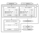
- the similarity calculation unit 60 includes a feature amount calculation unit 100, an individual similarity and total similarity calculation unit 110, and an attention area emphasis processing unit 111.
- the feature amount calculation unit 101 of the inspection image and the feature amount calculation unit 102 of the reference image calculate the feature amount of the image transmitted from the inspection image acquisition unit 55 and the reference image storage memory 80.
- the feature amount is preferably classified according to whether the observation target is located at at least one of the surface layer, the middle layer, and the deep layer. Further, the feature amount is preferably a value obtained from the shape and color of the observation target or those shapes and colors. Items of feature amount include, for example, blood vessel density, blood vessel shape, number of blood vessel branches, blood vessel thickness, blood vessel length, blood vessel tortuosity, blood vessel depth, glandular shape, and glandular opening shape. , The length of the blood vessel, the degree of tortuosity of the blood vessel, and the color information.
- the feature amount is preferably a value obtained by at least one of these or a combination of two or more of these.
- the item of the feature amount is not limited to this, and may be added as appropriate depending on the usage situation.
- the total feature amount of each endoscopic image calculated by the feature amount calculation unit 101 of the inspection image or the feature amount calculation unit 102 of the reference image is used as the total feature amount. As shown in FIG. 15, the total feature amount is transmitted to the attention area enhancement processing unit 111.
- the attention area enhancement processing unit 111 will be described later.
- the reference image and the individual feature amount related to this reference image are associated and stored in the reference image storage memory 80. May be good. Further, for the reference image for which the individual feature amount has been calculated in the past, the step of calculating the same individual feature amount may be skipped. This is to save the calculation area of the processor device 14.
- the value of the individual feature amount related to each inspection image calculated by the feature amount calculation unit 100 or each diagnosed reference image is transmitted to the individual similarity degree and the total similarity degree calculation unit 110. ..
- the individual similarity and total similarity calculation unit 110 relates to an inspection image which is a first illumination light image, a second illumination light image, or a superposed image, and a plurality of one or more types of diagnosed reference images. Compare individual feature quantities. The comparison of the individual feature quantities is performed between the first illumination light image and the diagnosed white light image, or between the second illumination light image and the diagnosed special light image, and the individual similarity between the images is performed. Calculate the degree. In the specific example of FIG. 15, the shape of the blood vessel on the surface layer according to the inspection image, the individual feature amount of the branch is A1, the individual feature amount of the uniformity of the blood vessel on the surface layer is A2, and so on, and the shape of the blood vessel on the surface layer according to the reference image.
- the individual feature amount of the branch is a1
- the individual feature amount of the uniformity of the blood vessels on the surface layer is a2, and so on
- the values related to the items of the individual feature amount are calculated for each of the inspection image and the reference image.
- the total features are calculated by summing them up.
- the total feature amount of the inspection image is calculated as ABC
- the total feature amount of the reference image is calculated as abc.
- the total feature amount is transmitted to the attention area highlighting processing unit 111, and is used in an analysis process for highlighting the attention area in each of the inspection image and the reference image.
- the individual feature amounts related to the items of each feature amount are transmitted to the individual similarity degree and the total similarity degree calculation unit 110.
- the values of A1 and a1 are compared with respect to the individual similarity related to the shape / branch of the blood vessel on the surface layer (denoted as “A1 vs a1” in FIG. 15), and the individual similarity is calculated to be ⁇ 1. is doing. Subsequently, the total sum of the individual similarity is calculated as the total similarity and transmitted to the reference image selection unit 61. In the specific example of FIG. 15, the total similarity between the inspection image and the reference image is calculated as a value of ⁇ , and this value is transmitted to the reference image selection unit 61.
- the similarity calculation unit 60 may be equipped with artificial intelligence using a Convolutional Neural Network or the like, and the total similarity may be calculated using the artificial intelligence.
- the similarity calculation unit 60 is configured by a learning model for similarity output by machine learning or the like, and the inspection image and the reference image stored in the reference image storage memory 80 are used as a learning model for similarity output. By inputting, it is preferable to output the total similarity for each reference image.
- the individual similarity and the total similarity are calculated between the superimposed image transmitted from the inspection image acquisition unit 55 and the superimposed image transmitted from the reference image storage memory 80. Will be done. If there is no diagnosed white light image for comparison with the first illumination light image or a diagnosed special light image for comparison with the second illumination light image, it is a reference image and has been diagnosed. The comparison is performed after color matching is performed with respect to the hue, color tone, etc. of the image so that the white light image or the diagnosed special light image can be compared with the first illumination light image or the second illumination light image.
- the reference image selection unit 61 receives one or a plurality of reference images and the total similarity calculated or output for each reference image from the similarity calculation unit 60. As shown in FIG. 16, the reference image selection unit 61 assigns a ranking to a plurality of reference images according to the total similarity. Subsequently, among the plurality of reference images, a reference image whose overall similarity satisfies a specific condition is selected and transmitted to the display control unit 62.
- the specific condition is a threshold value determined by the value of total similarity. This particular condition threshold is variable and can be set automatically or manually by the user. Specifically, a reference image having a total similarity higher than a certain value (threshold value) is selected and displayed.
- a reference image whose overall similarity is equal to or higher than a specific condition (greater than or equal to a threshold value) is selected as a reference image for display and transmitted to the display control unit 62.
- a reference image whose overall similarity is calculated to be ⁇ by comparison with an inspection image is transmitted to the reference image selection unit 61.
- the reference images whose total similarity is calculated to be 87, 95, 92, and 30, respectively, as shown in FIG. 16 are transmitted to the reference image selection unit 61.
- the reference image with an overall similarity of 95 is ranked first, the reference image with 92 is ranked second, the reference image with 87 is ranked third, and the reference image with a total similarity of 30 is ranked fourth.
- the specific condition is "total similarity is 31 or more”.
- the reference image having the total similarity of 30 does not satisfy a specific condition, it is not transmitted to the display control unit 62, the reference images having the total similarity of 95, 92, and 87 are selected, and the display control unit 62 is selected. Will be sent to.
- the reference image to be presented can be selected according to the value of the total similarity. For example, when a plurality of reference images are selected by the reference image selection unit 61 and the number of selected reference images is larger than expected by the user, the threshold value of the total similarity is increased to present only the reference images having higher similarity. can do.
- the attention area highlighting processing unit 111 performs the attention area highlighting process for highlighting the attention area in the inspection image or the reference image as marking according to the value of the total feature amount.
- the inspection image to which the attention area enhancement processing has been performed and the reference image to which the attention area enhancement processing has been performed are transmitted to the display control unit 62 and displayed on the display 15.
- the inspection image to which the attention area enhancement processing has been performed is simply referred to as an inspection image
- the reference image to which the attention area enhancement processing has been performed is also simply referred to as a reference image. It is not necessary to perform the attention area enhancement process.
- the inspection image or the reference image on which the marking of the region of interest is not displayed is transmitted to the display control unit 62 and displayed on the display 15.
- the display mode of the marking based on the attention area enhancement process As shown in FIG. 17, a circular frame and a reference numeral (inspection image: I1, reference image: R1) surrounding the attention area are shown. ..
- the marking display mode is not limited to this example, and the shape, color, size, and thickness can be appropriately changed. When there are a plurality of areas of interest, markings having different shapes, colors, sizes, thicknesses, etc. may be used for each area of interest. Symbols such as numbers and letters may be added to each marking. If the user is aware that the lesion is extremely sensitive, it may be displayed in yellow, red, or the like.
- the value of the total feature amount for displaying the marking is set by a threshold value set automatically or manually.
- the user can appropriately set whether or not to display the marking on each endoscope image displayed on the display 15. With the above configuration, the user can easily recognize the area of interest.
- the display control unit 62 makes the inspection image and the reference image selected by the reference image selection unit 61 into one screen, and displays them on the display 15 as the reference image presentation screen 120. Further, it is preferable to display the reference image, the diagnosis result of the reference image, the total similarity, and the ranking of the total similarity on one screen as the reference image presentation screen 120.
- a display example in the first embodiment is shown in FIG. In FIG. 17, the inspection image number, the inspection image type 121, the inspection image (in this case, the superimposed image) 123 in which the attention area is highlighted, the reference image number, the reference image type 122, and the attention area are highlighted on the display 15.
- the reference image (white light image) 124, the diagnosis result 125 of the reference image, and the overall similarity and the order 126 of the overall similarity are displayed.
- the user can improve the discrimination accuracy of the image diagnosis by comparing the inspection image with the diagnosed reference image. Further, it facilitates information transmission between the user and a third party who is observing the display 15 at the same time.
- the inspection image lacks information for comparison with the reference image (for example, the size of the area of interest in the screen, screen blur, brightness, focus). It is possible to urge the user in the above and prevent the inspection from being redone.
- the ranking switching icon 127 is displayed on the reference image presentation screen 120 as an operation icon for switching the displayed reference image 124 to a reference image having a higher or lower overall similarity.
- the order switching icon 127 is provided on the right side or the left side of the reference image 124.
- the order switching icon 127 is represented by a triangular icon and faces rightward or leftward.
- the shape and display mode of the order switching icon 127 are not limited to this.
- an image type switching icon 128 indicating that the types of the inspection image and the reference image can be switched is displayed on the upper side or the lower side of the inspection image 123 and the reference image 124.
- the image type switching icon 128 is represented by a triangle and faces upward or downward.
- the shape and display mode of the image type switching icon 128 are not limited to this.
- the user operates the ranking switching icon 127 or the image type switching icon 128 by using the mouse or touch panel of the UI 16.
- the UI 16 and the reference image presentation switch 12g may be combined and operated. For example, the user selects either the ranking switching icon 127 or the image type switching icon 128 via the mouse or touch panel of the UI 16, activates the selected icon, and then activates the reference image presentation switch. When you press 12g, the display corresponding to the activated icon is switched.
- the reference image presentation switch 12g is pressed after activating the rank switching icon 127 on the right side.
- the display of the diagnosis result of the reference image, the overall similarity and the ranking of the overall similarity is switched, and the screen shown in FIG. 18 is displayed. That is, the reference image presentation switch 12g can also function as a toggle switch for switching the display of the reference image.
- the order switching icon 127 on the right side is operated to switch the display to the reference image having a lower overall similarity, and the reference image presentation switch 12g is pressed faster (than normal pressing).
- the order switching icon 127 on the left side may be operated to switch the display to the reference image having the higher overall similarity.
- the endoscope 12 and UI 16 may be newly provided with a button for switching the order and a button for switching the display image.
- the image displayed as the inspection image 123 is a superimposed image
- the image displayed as the reference image 124 is a diagnosed white light image. ..
- the image that can be displayed on the display 15 as the inspection image 123 is at least one of the first illumination light image, the second illumination light image, and the superimposed image, and the image type switching icon 128 on the inspection image side is operated. Can be switched between each other.
- the image that can be displayed as the reference image 124 is a diagnosed image stored in the reference image storage memory 80, for example, a diagnosed white light image or a diagnosed special light image.
- By operating the image type switching icon 128 on the reference image side it is possible to switch between the diagnosed white light image and the diagnosed special light image.
- the operation method of the image type switching icon 128 on the inspection image side or the reference image side is the same as the operation method of the image type switching icon 128.
- the inspection image 123 being displayed is switched from the superimposed image to the second illumination light image.
- the image type switching icon 128 on the reference image side is operated, the displayed reference image 124 is switched from the white light image to the special light image.
- the special light image (second illumination light image) is set with the image type switching icon 128 on the inspection image side on the reference image presentation screen 120, the image type switching icon 128 on the reference image side does not have to be operated.
- the display may be automatically switched to the display of the reference image (special light image) captured by the same type of special light as the inspection image. In this case, it is preferable to be able to set to automatically switch the type of the reference image according to the type of the inspection image.
- a second illumination light image of a type that the user is not accustomed to is used as an inspection image. It may be displayed.
- the types of second illumination light increase, the user must learn how to distinguish subjects taken with all types of second illumination light, so depending on the type of second illumination light, the user may observe. It is assumed that you are not used to it. With the above configuration, it is possible to observe the reference image captured by using the same type of second illumination light as the type of second illumination light of the inspection image, so that it is easy to observe the type of second illumination light image that the user is not familiar with. Can be.
- the reference image selection unit 61 sends an instruction to display a warning to the display control unit 62.
- a warning is displayed on the reference image presentation screen 120.
- the frame showing the order of the total similarity and the total similarity may be displayed thicker than usual, and the warning display 130 may be used.
- the warning display 130 is not limited to this method. For example, you may change the color, size, and thickness of the overall similarity and the ranking of the overall similarity, and a warning message "The reference image does not exist" is displayed at the position where the reference image is normally displayed.
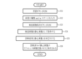
- step S11 When the reference image presentation switch 12g is pressed when the inspection image is acquired or is (step S11), the reference image presentation mode switching unit 56 is operated to switch to the reference image presentation mode (step S12).
- the inspection image and the diagnosed reference image stored in the reference image storage memory 80 are transmitted to the similarity calculation unit 60 (step S13, step S14), and the overall similarity between the inspection image and the reference image is achieved.
- the degree is calculated (step S15).
- a reference image satisfying a specific condition is selected by the reference image selection unit (step S16), and finally, the inspection image, the reference image satisfying the specific condition, and the total similarity between the images are obtained. , It is displayed on the display 15 as the reference image presentation screen 120 (step S17).
- the mode may be automatically switched to the reference image presentation mode.
- the detection of the region of interest is used as a trigger to automatically switch to the reference image presentation mode and display the inspection image and the reference image without pressing the reference image presentation switch 12g. Display on 15.
- the processing and the like after switching to the reference image presentation mode are the same as the processing and the like when manually switching by the reference image presentation switch 12g.
- the second embodiment describes a case where the inspection image saving button 150, the still image acquisition unit 63, and the diagnosis result input unit 64 are provided in order to save the inspection image as a reference image.
- FIG. 22 is displayed on the reference image presentation screen 120.
- the inspection image number, the inspection image type 121, the inspection image (superimposed image) 123 in which the region of interest is highlighted, the reference image number, and the reference are displayed as the reference image presentation screen 120 in the first embodiment.
- Form 142, inspection image save button 150, screenshot button 151, and treatment start button 152 are displayed.
- the user When the user recognizes that the diagnosis result of the reference image and the diagnosis result of the inspection image do not match and the rejection button 141 is pressed, the user inputs the diagnosis result related to the inspection image into the diagnosis result input form 142 through the UI 16. can do.
- the denial button 141 When the denial button 141 is pressed, the diagnosis result is input, and the inspection image save button 150 is pressed, the still image acquisition unit 63 acquires the inspection image as a still image, and the diagnosis result input unit 64 serves as a still image.
- the acquired inspection image, the feature amount, and the diagnosis result input by the user can be associated with each other and stored in the reference image storage memory 80 as a new diagnosed reference image.
- the still image acquisition instruction switch 12h may be used as a trigger for acquiring the inspection image.
- the denial button 141 is pressed, the diagnosis result is input to the diagnosis result input form 142, and then the inspection image save button 150 or the still image acquisition instruction switch 12h is pressed.
- the denial button 141 is pressed and the diagnosis result is input.
- the attention region I1 of the inspection image is different from the discrimination result (tumor type is Type 1 and tumor stage is Stage 1) related to the attention region R1 of the reference image, the user. If the judgment is made, pressing the denial button 141 enables input to the diagnosis result input form 142.
- the diagnosis result for example, the type of the tumor is Type 1 and the stage of the tumor is Stage 2 related to the region of interest I1 of the examination image diagnosed by the user is input and the examination image save button 150 is pressed, it is currently displayed.
- the examination image 123 is acquired as a still image and transmitted to the diagnosis result input unit 64, and in the diagnosis result input unit 64, the diagnosis result "the type of tumor is Type 1 and the stage of the tumor is Stage 2" is associated with the still image.
- the inspection image and the diagnosis result associated with the inspection image can be stored in the reference image storage memory 80 as a diagnosed reference image.
- AI Artificial Intelligence
- step S21 when the denial button 141 is pressed on the reference image presentation screen 120 (step S21), the diagnosis result is input to the diagnosis result input form 142 (step S22).
- step S23 when the inspection image save button 150 is pressed (step S23), the still image acquisition unit 63 acquires the inspection image as a still image (step S24).
- step S25 the diagnosis result input unit 64 associates the inspection image acquired as a still image with the diagnosis result input to the diagnosis result input form 142 (step S25).
- step S26 the still image that has been diagnosed due to the association of the diagnosis results is newly stored in the reference image storage memory 80 (step S26).
- the image displayed as the reference image by default on the reference image presentation screen 120 is a superimposed image. ..
- the image to be displayed as the reference image is at least one of a white light image (first illumination light image), a special light image (second illumination light image), and a superimposed image, and the reference image presentation switch 12g. It is preferable that they can be switched to each other by pressing.
- the screenshot button 151 is displayed on the reference image presentation screen 120.
- the reference image presentation screen 120 displayed on the display 15 can be acquired as a still image and saved in a memory (not shown).
- the reference image presentation screen 120 can be recorded on a storage medium such as an inspection recording system or an electronic medical record.
- case records can be easily collected during the examination.
- the treatment start button 152 is displayed on the reference image presentation screen 120.
- the treatment start time is recorded in a memory (not shown).
- the treatment start time can be recorded on a storage medium such as an inspection recording system or an electronic medical record. Further, when the inspection image is acquired as a still image, the time required for the treatment of the region of interest in the still image can be saved in association with the still image.
- the medical image processing apparatus of the present invention is applied to an endoscopic system that acquires an endoscopic image as a medical image, but various internal organs such as a capsule endoscope are applied. Needless to say, it is applicable to the spectroscopic system, and as other medical images, X-ray images, CT images, MR images, ultrasonic images, pathological images, PET (Positron Emission Tomography) images, etc.
- the medical image processing apparatus of the present invention can be applied to various medical imaging devices to be acquired.
- the hardware-like structure of the processing unit that executes various processes such as the illumination light image generation unit 55b, the superimposed image generation unit 55c, and the central control unit 70 includes various processors as shown below. Is. For various processors, the circuit configuration is changed after manufacturing the CPU (Central Processing Unit), FPGA (Field Programmable Gate Array), etc., which are general-purpose processors that execute software (programs) and function as various processing units. It includes a programmable logic device (PLD), which is a possible processor, a dedicated electric circuit, which is a processor having a circuit configuration specially designed for executing various processes, and the like.
- PLD programmable logic device
- One processing unit may be composed of one of these various processors, and may be composed of a combination of two or more processors of the same type or different types (for example, a plurality of FPGAs or a combination of a CPU and an FPGA). You may. Further, a plurality of processing units may be configured by one processor. As an example of configuring a plurality of processing units with one processor, first, as represented by a computer such as a client or a server, one processor is configured by a combination of one or more CPUs and software. There is a form in which this processor functions as a plurality of processing units.
- SoC System On Chip
- the various processing units are configured by using one or more of the above-mentioned various processors as a hardware-like structure.
- the hardware-like structure of these various processors is, more specifically, an electric circuit (circuitry) in which circuit elements such as semiconductor elements are combined.
- the hardware structure of the storage unit is a storage device such as an HDD (hard disk drive) or SSD (solid state drive).
Landscapes
- Health & Medical Sciences (AREA)
- Life Sciences & Earth Sciences (AREA)
- Physics & Mathematics (AREA)
- Surgery (AREA)
- Optics & Photonics (AREA)
- Biomedical Technology (AREA)
- Animal Behavior & Ethology (AREA)
- Radiology & Medical Imaging (AREA)
- Nuclear Medicine, Radiotherapy & Molecular Imaging (AREA)
- Engineering & Computer Science (AREA)
- Biophysics (AREA)
- Heart & Thoracic Surgery (AREA)
- Medical Informatics (AREA)
- Molecular Biology (AREA)
- Pathology (AREA)
- General Health & Medical Sciences (AREA)
- Public Health (AREA)
- Veterinary Medicine (AREA)
- Astronomy & Astrophysics (AREA)
- General Physics & Mathematics (AREA)
- Endoscopes (AREA)
- Instruments For Viewing The Inside Of Hollow Bodies (AREA)
Priority Applications (2)
| Application Number | Priority Date | Filing Date | Title |
|---|---|---|---|
| JP2022538577A JP7386347B2 (ja) | 2020-07-21 | 2021-02-09 | 内視鏡システム及びその作動方法 |
| CN202180059472.2A CN116134363A (zh) | 2020-07-21 | 2021-02-09 | 内窥镜系统及其工作方法 |
Applications Claiming Priority (2)
| Application Number | Priority Date | Filing Date | Title |
|---|---|---|---|
| JP2020-124793 | 2020-07-21 | ||
| JP2020124793 | 2020-07-21 |
Publications (1)
| Publication Number | Publication Date |
|---|---|
| WO2022018894A1 true WO2022018894A1 (ja) | 2022-01-27 |
Family
ID=79729362
Family Applications (1)
| Application Number | Title | Priority Date | Filing Date |
|---|---|---|---|
| PCT/JP2021/004825 Ceased WO2022018894A1 (ja) | 2020-07-21 | 2021-02-09 | 内視鏡システム及びその作動方法 |
Country Status (3)
| Country | Link |
|---|---|
| JP (1) | JP7386347B2 (https=) |
| CN (1) | CN116134363A (https=) |
| WO (1) | WO2022018894A1 (https=) |
Cited By (2)
| Publication number | Priority date | Publication date | Assignee | Title |
|---|---|---|---|---|
| US20220391615A1 (en) * | 2021-06-01 | 2022-12-08 | Hummingbird Technologies Limited | Tool for counting and sizing plants in a field |
| CN115835448A (zh) * | 2022-12-28 | 2023-03-21 | 无锡车联天下信息技术有限公司 | 一种调节灯光的方法、装置、内窥镜设备及介质 |
Citations (5)
| Publication number | Priority date | Publication date | Assignee | Title |
|---|---|---|---|---|
| WO2015146519A1 (ja) * | 2014-03-27 | 2015-10-01 | 富士フイルム株式会社 | 類似症例検索装置、類似症例検索方法、及び類似症例検索プログラム |
| WO2017199509A1 (ja) * | 2016-05-19 | 2017-11-23 | オリンパス株式会社 | 生体観察システム |
| WO2018159347A1 (ja) * | 2017-02-28 | 2018-09-07 | 富士フイルム株式会社 | プロセッサ装置、内視鏡システム及びプロセッサ装置の作動方法 |
| WO2018180631A1 (ja) * | 2017-03-30 | 2018-10-04 | 富士フイルム株式会社 | 医療用画像処理装置及び内視鏡システム並びに医療用画像処理装置の作動方法 |
| WO2020054255A1 (ja) * | 2018-09-12 | 2020-03-19 | 富士フイルム株式会社 | 内視鏡装置、内視鏡プロセッサ、及び内視鏡装置の操作方法 |
Family Cites Families (2)
| Publication number | Priority date | Publication date | Assignee | Title |
|---|---|---|---|---|
| JP5405445B2 (ja) * | 2010-12-17 | 2014-02-05 | 富士フイルム株式会社 | 内視鏡装置 |
| JP6392570B2 (ja) * | 2014-07-11 | 2018-09-19 | オリンパス株式会社 | 画像処理装置、画像処理装置の作動方法、画像処理プログラム、及び内視鏡システム |
-
2021
- 2021-02-09 JP JP2022538577A patent/JP7386347B2/ja active Active
- 2021-02-09 CN CN202180059472.2A patent/CN116134363A/zh active Pending
- 2021-02-09 WO PCT/JP2021/004825 patent/WO2022018894A1/ja not_active Ceased
Patent Citations (5)
| Publication number | Priority date | Publication date | Assignee | Title |
|---|---|---|---|---|
| WO2015146519A1 (ja) * | 2014-03-27 | 2015-10-01 | 富士フイルム株式会社 | 類似症例検索装置、類似症例検索方法、及び類似症例検索プログラム |
| WO2017199509A1 (ja) * | 2016-05-19 | 2017-11-23 | オリンパス株式会社 | 生体観察システム |
| WO2018159347A1 (ja) * | 2017-02-28 | 2018-09-07 | 富士フイルム株式会社 | プロセッサ装置、内視鏡システム及びプロセッサ装置の作動方法 |
| WO2018180631A1 (ja) * | 2017-03-30 | 2018-10-04 | 富士フイルム株式会社 | 医療用画像処理装置及び内視鏡システム並びに医療用画像処理装置の作動方法 |
| WO2020054255A1 (ja) * | 2018-09-12 | 2020-03-19 | 富士フイルム株式会社 | 内視鏡装置、内視鏡プロセッサ、及び内視鏡装置の操作方法 |
Cited By (2)
| Publication number | Priority date | Publication date | Assignee | Title |
|---|---|---|---|---|
| US20220391615A1 (en) * | 2021-06-01 | 2022-12-08 | Hummingbird Technologies Limited | Tool for counting and sizing plants in a field |
| CN115835448A (zh) * | 2022-12-28 | 2023-03-21 | 无锡车联天下信息技术有限公司 | 一种调节灯光的方法、装置、内窥镜设备及介质 |
Also Published As
| Publication number | Publication date |
|---|---|
| JP7386347B2 (ja) | 2023-11-24 |
| JPWO2022018894A1 (https=) | 2022-01-27 |
| CN116134363A (zh) | 2023-05-16 |
Similar Documents
| Publication | Publication Date | Title |
|---|---|---|
| JP7847176B2 (ja) | 画像処理装置 | |
| JP6785948B2 (ja) | 医療用画像処理装置及び内視鏡システム並びに医療用画像処理装置の作動方法 | |
| JP7542585B2 (ja) | 画像処理装置、内視鏡システム及び画像処理装置の作動方法 | |
| US20240206705A1 (en) | Medical image processing device | |
| JP6917518B2 (ja) | 内視鏡システム | |
| JP7335399B2 (ja) | 医用画像処理装置及び内視鏡システム並びに医用画像処理装置の作動方法 | |
| CN116133572B (zh) | 图像分析处理装置、内窥镜系统、图像分析处理装置的工作方法及存储器 | |
| WO2022209390A1 (ja) | 内視鏡システム及びその作動方法 | |
| JP7402314B2 (ja) | 医用画像処理システム、医用画像処理システムの作動方法 | |
| WO2021229684A1 (ja) | 画像処理システム、内視鏡システム、画像処理方法及び学習方法 | |
| US20230101620A1 (en) | Medical image processing apparatus, endoscope system, method of operating medical image processing apparatus, and non-transitory computer readable medium | |
| JP7386347B2 (ja) | 内視鏡システム及びその作動方法 | |
| WO2020039929A1 (ja) | 医用画像処理装置及び内視鏡システム並びに医用画像処理装置の作動方法 | |
| JP6923129B2 (ja) | 情報処理装置、プログラム、方法及びシステム | |
| WO2022014258A1 (ja) | プロセッサ装置、プロセッサ装置の作動方法 | |
| WO2022071413A1 (ja) | 画像処理装置、内視鏡システム、画像処理装置の作動方法、及び画像処理装置用プログラム | |
| JP7593796B2 (ja) | 医用画像処理システム、医用画像処理システムの作動方法 | |
| JP7506159B2 (ja) | 内視鏡システム及びその作動方法 | |
| JP7307709B2 (ja) | 処置具管理システム、内視鏡システム及びその作動方法 | |
| JP7815232B2 (ja) | 医療画像処理装置及び内視鏡システム | |
| WO2023007896A1 (ja) | 内視鏡システム、プロセッサ装置及びその作動方法 | |
| WO2022059233A1 (ja) | 画像処理装置、内視鏡システム、画像処理装置の作動方法、及び画像処理装置用プログラム | |
| WO2022044371A1 (ja) | 内視鏡システム及びその作動方法 | |
| CN117500426A (zh) | 医疗图像处理装置、内窥镜系统及医疗图像处理装置的工作方法 |
Legal Events
| Date | Code | Title | Description |
|---|---|---|---|
| 121 | Ep: the epo has been informed by wipo that ep was designated in this application |
Ref document number: 21845451 Country of ref document: EP Kind code of ref document: A1 |
|
| ENP | Entry into the national phase |
Ref document number: 2022538577 Country of ref document: JP Kind code of ref document: A |
|
| NENP | Non-entry into the national phase |
Ref country code: DE |
|
| 122 | Ep: pct application non-entry in european phase |
Ref document number: 21845451 Country of ref document: EP Kind code of ref document: A1 |