WO2022018894A1 - Endoscope system and method for operating same - Google Patents
Endoscope system and method for operating same Download PDFInfo
- Publication number
- WO2022018894A1 WO2022018894A1 PCT/JP2021/004825 JP2021004825W WO2022018894A1 WO 2022018894 A1 WO2022018894 A1 WO 2022018894A1 JP 2021004825 W JP2021004825 W JP 2021004825W WO 2022018894 A1 WO2022018894 A1 WO 2022018894A1
- Authority
- WO
- WIPO (PCT)
- Prior art keywords
- image
- reference image
- illumination light
- light
- illumination
- Prior art date
Links
Images


Classifications
-
- A—HUMAN NECESSITIES
- A61—MEDICAL OR VETERINARY SCIENCE; HYGIENE
- A61B—DIAGNOSIS; SURGERY; IDENTIFICATION
- A61B1/00—Instruments for performing medical examinations of the interior of cavities or tubes of the body by visual or photographical inspection, e.g. endoscopes; Illuminating arrangements therefor
- A61B1/04—Instruments for performing medical examinations of the interior of cavities or tubes of the body by visual or photographical inspection, e.g. endoscopes; Illuminating arrangements therefor combined with photographic or television appliances
- A61B1/045—Control thereof
-
- G—PHYSICS
- G02—OPTICS
- G02B—OPTICAL ELEMENTS, SYSTEMS OR APPARATUS
- G02B23/00—Telescopes, e.g. binoculars; Periscopes; Instruments for viewing the inside of hollow bodies; Viewfinders; Optical aiming or sighting devices
- G02B23/24—Instruments or systems for viewing the inside of hollow bodies, e.g. fibrescopes
Definitions
- the present invention relates to an endoscopic system that displays an inspection image and a reference image having a high degree of similarity to the inspection image among the diagnosed reference images, and an operation method thereof.
- image diagnosis such as diagnosis of a patient's medical condition and follow-up is performed using endoscopic images and the like. Based on such diagnostic imaging, doctors and others make decisions on treatment policies.
- the person who performs the image diagnosis such as a doctor is inexperienced, or if the image to be diagnosed is a rare case even if he / she has experience, and the image is out of the field of specialization, the doctor diagnoses it. May be difficult to do reliably.
- Patent Document 1 a first medical image obtained by imaging an observation target with an imaging unit is compared with a second medical image stored in a database, and a second image feature having a high degree of similarity is compared.
- the medical images of the above are searched, and the searched second medical images are displayed side by side on the display device.
- the white light and multiple types of special light As described above, if the operation of switching each time during the inspection is performed, it will impose a burden on the user. Therefore, the white light and multiple types of special light, etc. It is preferable to automatically switch a plurality of illumination lights of the above to illuminate a lesion or the like, and provide a white light image based on the white light and a special light image based on a plurality of types of special light as an inspection image.
- a plurality of types of inspection images are acquired by automatic lighting switching of illumination light in this way, and each inspection image and a reference image for comparison with each inspection image are displayed together. Is not listed.
- the present invention provides a plurality of types of inspection images based on a plurality of types of illumination light and a reference image for comparing each inspection image without imposing a burden on the user by switching the illumination of a plurality of types of illumination light. It is an object of the present invention to provide an endoscopic system that can be displayed on a display and a method of operating the same.
- the endoscope system of the present invention includes a light source unit and an image control processor.
- the light source unit emits first illumination light and second illumination light having different emission spectra from each other.
- the light source unit automatically switches between the first lighting period for emitting the first illumination light and the second illumination period for emitting the second illumination light, the light source unit emits the first illumination light in the first emission pattern, and the first emission pattern is used. 2 Illumination light is emitted in the second emission pattern.
- the image control processor captures the first illumination light image captured by irradiating the subject with the first illumination light, the second illumination light image captured by irradiating the subject with the second illumination light, and the second illumination light image.
- At least one of the superimposed images obtained by superimposing and displaying the analysis result obtained by the analysis processing on the first illumination light image is acquired as an inspection image, and the inspection image and the reference image are compared based on the feature amount.
- the reference image storage memory that calculates the total similarity and stores the diagnosed reference image, and among the plurality of reference images for which the total similarity has been calculated, the reference image whose total similarity satisfies a specific condition is selected. Select and display the inspection image and the selected reference image on the display.
- the image control processor calculates the feature amount of the reference image, calculates the total similarity based on the feature amount of the inspection image and the reference image, and then sets a specific condition. It is preferable to display the satisfying reference image and the inspection image.
- the display of the reference image can be switched according to the ranking of the overall similarity.
- the image to be displayed as an inspection image is at least one of a superimposed image, a first illumination light image, and a second illumination light image, and it is preferable that the images can be switched between each other.
- the image displayed as the reference image is either a white light image or a special light image, and it is preferable that the images can be switched between each other.
- the inspection image and the reference image it is preferable to compare the feature amounts of the inspection image and the reference image between the first illumination light image and the white light image, or between the second illumination light image and the special light image. It is preferable to display a warning when a specific condition is not met. When selecting a plurality of reference images, it is preferable that specific conditions can be changed.
- the inspection image can be acquired as a still image and the still image can be saved as a reference image in the reference image storage memory. It is preferable that the still image and the diagnosis result can be associated with each other and saved in the reference image storage memory as a new diagnosed reference image.
- the image control processor calculates the feature amount of the reference image, calculates the total similarity based on the feature amount, and then sets the reference image to satisfy specific conditions. It is preferable to display the inspection image. It is preferable that the image control processor outputs the total similarity for each reference image by inputting the inspection image and the reference image stored in the reference image storage memory into the learning model for similarity output. ..
- the number of frames in the first lighting period is the same in each first lighting period, and the number of frames in the first lighting period is different in each first lighting period. It is preferably any one of the first B emission patterns.
- the second emission pattern is a second A pattern in which the number of frames in the second illumination period is the same in each second illumination period, and the emission spectrum of the second illumination light is the same in each second illumination period.
- the number of frames is different in each second illumination period, and the emission spectrum of the second illumination light is the same in each second illumination period.
- the second C pattern and the number of frames in the second illumination period are different from each other in each second illumination period, and the emission spectrum of the second illumination light is any one of the second D patterns different in each second illumination period.
- the method of operating the endoscope system of the present invention is a light source unit that emits a first illumination light and a second illumination light having different emission spectra from each other, and a first illumination period and a second illumination that emit the first illumination light.
- a light source unit that emits the first illumination light in the first emission pattern and emits the second illumination light in the second emission pattern when automatically switching between the second illumination period that emits light, and for image control.
- the image control processor irradiates the subject with the first illumination light and captures the first illumination light image, and irradiates the subject with the second illumination light and captures the image.
- At least one of the illumination light image and the superimposed image obtained by superimposing the analysis result obtained by analyzing the second illumination light image on the first illumination light image is acquired as an inspection image, and the inspection image is used.
- the inspection image is used.
- a plurality of reference images for which the total similarity has been calculated by comparing the reference image with the reference image based on the feature amount to calculate the total similarity and referring to the reference image storage memory for storing the diagnosed reference image.
- a reference image whose overall similarity satisfies a specific condition is selected, and the inspection image and the selected reference image are displayed on the display.
- the endoscope system 10 includes an endoscope 12, a light source device 13, a processor device 14, a display 15, and a UI (User InterFace) 16.
- the endoscope 12 is optically connected to the light source device 13 and electrically connected to the processor device 14.
- the endoscope 12 has an insertion portion 12a, an operation portion 12b, a bending portion 12c, and a tip portion 12d.
- the insertion portion 12a is inserted into the body to be observed.
- the operation portion 12b is provided at the base end portion of the insertion portion 12a.
- the curved portion 12c and the tip portion 12d are provided on the tip end side of the insertion portion 12a.
- the curved portion 12c bends by operating the angle knob 12e of the operating portion 12b.
- the tip portion 12d is directed in a desired direction by the bending motion of the bending portion 12c.
- the operation unit 12b is provided with an angle knob 12e, an observation mode changeover switch 12f, a reference image presentation switch 12g, and a zoom operation unit 12i.
- the observation mode changeover switch 12f is used for the observation mode changeover operation.
- the reference image presentation switch 12g is used for presenting the reference image.
- the still image acquisition instruction switch 12h is used for an instruction to acquire a still image to be observed.
- the zoom operation unit 12i is used to operate the zoom lens 42.
- the endoscope system 10 has three modes as observation modes: a first illumination observation mode, a second illumination observation mode, and a superimposition mode.
- the observation mode changeover switch 12f When the observation mode changeover switch 12f is pressed, the mode is switched via the image processing changeover unit 54. Further, the endoscope system 10 has two display modes, an inspection image display mode and a reference image presentation mode. When the reference image presentation switch 12g is pressed, the display mode is switched via the reference image presentation mode switching unit 56. That is, as the modes mounted on the endoscope system of the present invention, the inspection image display first illumination observation mode, the inspection image display second illumination observation mode, the inspection image display superimposition mode, the reference image presentation first illumination observation mode, and the like.
- a reference image display second illumination observation mode There are a total of six modes, a reference image display second illumination observation mode and a reference image presentation superimposition mode. From this paragraph onward, when the term "inspection image display mode” is simply used, there are three modes: inspection image display first illumination observation mode, inspection image display second illumination observation mode, and inspection image display superimposition mode. It refers to all cases, but as a default, the inspection image display superimposition mode is assumed. Further, when the term "reference image presentation mode" is simply described, all three modes of the reference image presentation first illumination observation mode, the reference image display second illumination observation mode, and the reference image presentation superimposition mode are used. However, as a default, the reference image presentation superimposition mode is assumed.
- Inspection image display In the first illumination observation mode and the reference image presentation first illumination observation mode, normal light such as white light (first illumination light) is illuminated on the observation target and imaged, so that the first illumination has a natural hue.
- the optical image is displayed on the display 15 as a display unit.
- Inspection image display In the second illumination observation mode and the reference image presentation second illumination observation mode, a specific structure is imaged by illuminating the observation target with special light (second illumination light) whose wavelength band is different from that of normal light.
- the emphasized second illumination light image is displayed on the display 15.
- the inspection image display superimposition mode and the reference image presentation superimposition mode the first illumination light and the second illumination light having different emission spectra are switched to emit light, and the image based on the first illumination light is displayed on the display 15.
- the image based on the second illumination light is subjected to analysis processing such as processing related to AI (Artificial Intelligence) and processing for obtaining feature quantities related to the observation target.
- AI Artificial Intelligence
- the result of the analysis process is superimposed and displayed on the first illumination light image.
- the similarity calculation unit 60 calculates the value of the individual feature amount and the value of the total feature amount from the inspection image.
- the total feature amount is transmitted to the attention area enhancement processing unit 111 or the display control unit 62.
- the similarity calculation unit 60 will be described later (see FIG. 15).
- the screen displayed in the three modes of the observation mode is displayed on the display 15.
- the inspection image and the reference image satisfying a specific condition are displayed as the reference image presentation screen 120.
- the processor device 14 stores the still image to be observed in the memory (not shown) in the first lighting period, the second lighting period, or both. To.
- the still image storage in the reference image presentation mode will be described in detail later.
- the processor device 14 is electrically connected to the display 15 and the UI 16.
- the display 15 outputs and displays an image to be observed, information incidental to the image to be observed, and the like.
- the UI 16 has a keyboard, a mouse, a touch pad, a microphone, and the like, and has a function of accepting input operations such as function settings.
- a reference image storage memory 80 for recording an image, image information, or the like is connected to the processor device 14 (see FIGS. 2 and 14).
- the reference image storage memory 80 may be a storage on the Web system. Further, an external memory (not shown) may be connected to the processor device 14.
- the light source device 13 includes a light source unit 20 and a light source processor 21 that controls the light source unit 20.
- the light source unit 20 has, for example, a plurality of semiconductor light sources, each of which is turned on or off, and when the light source unit 20 is turned on, the light emission amount of each semiconductor light source is controlled to emit illumination light for illuminating the observation target.
- the light source unit 20 is a V-LED (Violet Light Emitting Diode) 20a, a B-LED (Blue Light Emitting Diode) 20b, a G-LED (Green Light Emitting Diode) 20c, and an R-LED (Red Light Emitting Diode) 20d. It has 4 color LEDs.
- the V-LED generates purple light V having a center wavelength of 405 ⁇ 10 nm and a wavelength range of 380 to 420 nm.
- the B-LED generates blue light B having a center wavelength of 450 ⁇ 10 nm and a wavelength range of 420 to 500 nm.
- the G-LED produces green light G having a wavelength range of 480 to 600 nm.
- the R-LED produces red light R with a center wavelength of 620 to 630 nm and a wavelength range of 600 to 650 nm.
- the light source processor 21 controls the V-LED20a, B-LED20b, G-LED20c, and R-LED20d. By independently controlling each of the LEDs 20a to 20d, the light source processor 21 can emit purple light V, blue light B, green light G, or red light R by independently changing the amount of light. Further, the light source processor 21 emits white light having a light amount ratio of Vc: Bc: Gc: Rc among the purple light V, the blue light B, the green light G, and the red light R in the first illumination observation mode. As such, each LED 20a to 20d is controlled. In addition, Vc, Bc, Gc, Rc> 0.
- the first special light in which the light amount of the purple light V is larger than the light amounts of the other blue light B, the green light G, and the red light R may be used. ..
- a second special light in which the light amount of the green light G is larger than the light amounts of the other purple light V, the blue light B, and the red light R may be used. good.
- the light source processor 21 has a light amount ratio of Vk: Bs: Gs: purple light V, blue light B, green light G, and red light R as short-wavelength narrow-band light.
- Each LED 20a to 20d is controlled so as to emit special light that becomes Rs.
- the light amount ratio Vs: Bs: Gs: Rs is different from the light amount ratio Vc: Bc: Gc: Rc used in the first illumination observation mode, and is appropriately determined according to the observation purpose. For example, when emphasizing superficial blood vessels, it is preferable to make Vs larger than other Bs, Gs, Rs, and when emphasizing mesopelagic blood vessels, Gs is more than other Vs, Gs, Rs. It is also preferable to increase the size.
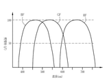
- the light source processor 21 emits the first illumination light in the first emission pattern when the first illumination light and the second illumination light are automatically switched and emitted in the superimposed mode, and the second illumination light is emitted. Is emitted in the second emission pattern.
- the first light emission pattern is the first A light emission pattern in which the number of frames in the first lighting period is the same in each first lighting period, and as shown in FIG. It is preferable that the number of frames in the first lighting period is any one of the first B emission patterns different in each first lighting period.
- the number of frames in the second illumination period is the same in each second illumination period, and the emission spectrum of the second illumination light is in each second illumination period.
- the number of frames in the second illumination period is the same in each of the second illumination periods, and the emission spectrum of the second illumination light is the same in the second illumination.
- the second B pattern differs in the period, as shown in FIG. 9, the number of frames in the second illumination period is different in each second illumination period, and the emission spectrum of the second illumination light is the first.
- the second C pattern which is the same in the two illumination periods, as shown in FIG. 10, the number of frames in the second illumination period is different in each second illumination period, and the emission spectrum of the second illumination light is different, respectively. It is preferably any one of the second D patterns that are different in the second illumination period of the above.
- the emission spectrum of the first illumination light may be the same or different in each first illumination period.
- the first lighting period is preferably longer than the second lighting period, and the first lighting period is preferably two frames or more.
- the first lighting period is set to 2 frames
- the second lighting period is set to 1 frame. Since the first illumination light is used to generate a display image to be displayed on the display 15, it is preferable to obtain a bright image by illuminating the observation target with the first illumination light.
- the first illumination light is preferably white light.
- the second illumination light is used for the analysis process, it is preferable to illuminate the observation target with the second illumination light to obtain an image suitable for the analysis process.
- purple light V, blue light B, green light G, and red light R may be used as the second illumination light.
- the second emission pattern is the second A pattern (the number of frames in the second illumination period: the same, the emission spectrum of the second illumination light: the same) or the second C pattern (the number of frames in the second illumination period: different, the second illumination).
- the second emission pattern is the second B pattern (number of frames in the second illumination period: same, emission spectrum of the second illumination light: different) or the second D pattern (number of frames in the second illumination period: different, second illumination light).
- emission spectrum different
- at least two of purple light V, blue light B, green light G, and red light R may be switched in a specific order to emit light in the second illumination period. preferable.
- FIG. 13 which will be described later, three lights, purple light V, green light G, and red light R, are sequentially emitted in that order.
- the first special light and the second special light are used as the second illumination light
- the first special light and the second special light are alternately used as the second emission pattern as the second B pattern or the second D pattern. It may be made to emit light.
- the frame refers to a unit of a period including at least a period from a specific timing to the completion of signal reading in the image pickup sensor 43.
- superficial blood vessels having a depth of 50 ⁇ m from the mucosal surface
- middle blood vessels having a depth of 200 ⁇ m from the mucosal surface
- deep blood vessels having a depth of 600 ⁇ m from the mucosal surface.
- purple light V that emphasizes surface blood vessels
- green light G that emphasizes middle layer blood vessels
- red light R that emphasizes deep blood vessels.
- the light intensity ratio includes the case where the ratio of at least one semiconductor light source is 0 (zero). Therefore, this includes the case where any one or more of the semiconductor light sources are not lit. For example, as in the case where the light amount ratio between purple light V, blue light B, green light G, and red light R is 1: 0: 0: 0, only one of the semiconductor light sources is turned on, and the other three are turned on. Even if it does not light up, it shall have a light intensity ratio.
- the light emitted by each of the LEDs 20a to 20d is incident on the light guide 23 via the optical path coupling portion 22 composed of a mirror, a lens, or the like.
- the light guide 23 is built in the endoscope 12 and a universal cord (a cord connecting the endoscope 12, the light source device 13 and the processor device 14).
- the light guide 23 propagates the light from the optical path coupling portion 22 to the tip portion 12d of the endoscope 12.
- An illumination optical system 30a and an image pickup optical system 30b are provided at the tip end portion 12d of the endoscope 12.
- the illumination optical system 30a has an illumination lens 31, and the illumination light propagated by the light guide 23 is applied to the observation target through the illumination lens 31.
- the image pickup optical system 30b has an objective lens 41 and an image pickup sensor 43. The light from the observation target due to the irradiation of the illumination light is incident on the image pickup sensor 43 via the objective lens 41 and the zoom lens 42. As a result, an image to be observed is formed on the image pickup sensor 43.
- the zoom lens 42 is a lens for enlarging the observation target, and moves between the telephoto end and the wide end by operating the zoom operation unit 12i.
- the image pickup sensor 43 is a primary color sensor, and is a B pixel (blue pixel) having a blue color filter, a G pixel (green pixel) having a green color filter, and an R pixel (red pixel) having a red color filter. It is equipped with three types of pixels.
- the blue color filter BF mainly transmits light in the blue band, specifically, light in the wavelength band having a wavelength band of 380 to 560 nm.
- the transmittance of the blue color filter BF peaks in the vicinity of the wavelength of 460 to 470 nm.
- the green color filter transmits GF, mainly light in the green band, specifically, light in the wavelength band of 460 to 620 nm.
- the red color filter RF mainly transmits light in the red band, specifically, light in the wavelength band of 580 to 760 nm.
- the image sensor 43 is preferably a CCD (Charge-Coupled Device) or a CMOS (Complementary Metal Oxide Semiconductor).
- the image pickup processor 44 controls the image pickup sensor 43. Specifically, the image signal is output from the image pickup sensor 43 by reading out the signal of the image pickup sensor 43 by the image pickup processor 44. In the first illumination observation mode, the image pickup processor 44 reads out the signal while the white light is exposed to the image pickup sensor 43, so that the Bc image signal is output from the B pixel of the image pickup sensor 43 and the Gc is output from the G pixel. The image signal is output, and the Rc image signal is output from the R pixel.
- the image pickup processor 44 reads out the signal while the special light is exposed to the image pickup sensor 43, so that the Bs image signal is output from the B pixel of the image pickup sensor 43 and the Gs is output from the G pixel.
- the image signal is output, and the Rs image signal is output from the R pixel.
- the image pickup processor 44 first reads out the signal from the image pickup sensor 43 in a state where the first illumination light is exposed to the image pickup sensor 43 during the first illumination period. Output an image signal.
- the period for outputting the first image signal is defined as the first imaging period.
- the first image signal includes a B1 image signal output from the B pixel, a G1 image signal output from the G pixel, and an R1 image signal output from the R pixel.
- the image pickup processor 44 outputs a second image signal from the image pickup sensor 43 by performing signal readout in a state where the image pickup sensor 43 is exposed to the second illumination light during the second illumination period.
- the period for outputting the second image signal is defined as the first imaging period.
- the second image signal includes a B2 image signal output from the B pixel, a G2 image signal output from the G pixel, and an R2 image signal output from the R pixel.
- the CDS / AGC (Correlated Double Sampling / Automatic Gain Control) circuit 46 performs correlated double sampling (CDS) and automatic gain control (AGC) on the analog image signal obtained from the image pickup sensor 43. ..
- CDS correlated double sampling
- AGC automatic gain control
- the image signal that has passed through the CDS / AGC circuit 45 is converted into a digital image signal by the A / D (Analog / Digital) converter 48.
- the digital image signal after A / D conversion is input to the processor device 14.
- the configuration and operation method of the processor device 14 described in the following paragraphs are common to the inspection image display mode and the reference image presentation mode with respect to the acquisition and display of the inspection image via the inspection image acquisition unit 55 and the display control unit 62. be.
- the central control unit 70 configured by the image control processor operates the program in the program memory, so that the image acquisition unit 50, the DSP (Digital Signal Processor) 52, and the noise reduction unit are operated.
- the functions of the 53, the image processing switching unit 54, the image processing unit 58, and the display control unit 62 are realized. Further, with the realization of the functions of the image processing unit 58, the functions of the first illumination light image generation unit 55a, the second illumination light image generation unit 55b, and the superimposed image generation unit 55c are realized in the inspection image acquisition unit 55. Will be done.
- the image control processor performs image processing based on the first image signal or the second image signal, and controls the display 15.
- the image acquisition unit 50 acquires a color image input from the endoscope 12.
- the color image includes a blue signal (B image signal), a green signal (G image signal), and a red signal (R image signal) output from the B pixel, the G pixel, and the R pixel of the image pickup sensor 43.
- the acquired color image is transmitted to the DSP 52.
- the DSP 52 performs various signal processing such as defect correction processing, offset processing, gain correction processing, matrix processing, gamma conversion processing, demosaic processing, and YC conversion processing on the received color image.
- the noise reduction unit 53 performs noise reduction processing by, for example, a moving average method, a median filter method, or the like on a color image that has been demosaic processed by DSP 52.
- the color image with reduced noise is input to the image processing switching unit 54.
- the image signal of each color after the gain correction processing is subjected to matrix processing to improve the color reproducibility. After that, the brightness and saturation of the color image are adjusted by the gamma conversion process.
- the color image after the matrix processing is subjected to demosaic processing (also referred to as isotropic processing and simultaneous processing), and a signal of the missing color of each pixel is generated by interpolation. By the demosaic processing, all the pixels have the signals of each color of RGB.
- the DSP 52 performs a YC conversion process on the color image after the demosaic process, and outputs the luminance signal Y, the color difference signal Cb, and the color difference signal Cr to the noise reduction unit 53.
- the color difference that expands the color difference between the normal part and the abnormal part (lesion part, etc.) included in the observation target with respect to the second image signal may be performed.
- Analysis processing may be performed on the second image signal which has undergone color difference expansion processing.
- the noise reduction unit 53 performs noise reduction processing by, for example, a moving average method, a median filter method, or the like on a color image that has been demosaic processed by DSP 52.
- the color image with reduced noise is input to the image processing switching unit 54.
- the image processing switching unit 54 sets the transmission destination of the image signal from the noise reduction unit 53 to the first illumination light image generation unit 55a and the second illumination light image in the inspection image acquisition unit 55. Switch to either one of the generation unit 55b and the superimposed image generation unit 55c.
- the image signal from the noise reduction unit 53 is input to the first illumination light image generation unit 55a.
- the second illumination observation mode is set, the image signal from the noise reduction unit 53 is input to the second illumination light image generation unit 55b.
- the superimposition mode the image signal from the noise reduction unit 53 is input to the superimposition image generation unit 55c.
- the first illumination light image generation unit 55a performs image processing for the first illumination light image on the input Rc image signal, Gc image signal, and Bc image signal for one frame.
- the image processing for the first illumination optical image includes color conversion processing such as 3 ⁇ 3 matrix processing, gradation conversion processing, and 3D LUT (Look Up Table) processing, color enhancement processing, and structural enhancement processing such as spatial frequency enhancement. Is included.
- the Rc image signal, the Gc image signal, and the Bc image signal that have undergone image processing for the first illumination light image are input to the display control unit 62 as the first illumination light image.
- the second illumination light image generation unit 55b performs image processing for the second illumination light image on the input Rs image signal, Gs image signal, and Bs image signal for one frame.
- the image processing for the second illumination optical image includes color conversion processing such as 3 ⁇ 3 matrix processing, gradation conversion processing, and 3D LUT (Look Up Table) processing, color enhancement processing, and structural enhancement processing such as spatial frequency enhancement. Is included.
- the Rs image signal, the Gs image signal, and the Bs image signal that have undergone image processing for the second illumination light image are input to the display control unit 62 as the second illumination light image.
- the superimposed image generation unit 55c performs the same image processing for the first illumination light image as described above on the input R1 image signal, G1 image signal, and B1 image signal for one frame.
- the R1 image signal, the G1 image signal, and the B1 image signal that have undergone image processing for the first illumination light image signal are used as display images.
- the superimposed image generation unit 55c performs analysis processing on the input R2 image signal, G2 image signal, and B2 image signal for a specific frame. Further, the superimposed image generation unit 55c performs display control processing for displaying the analysis result, which is the result of the analysis processing for calculating the feature amount, as the superimposed image.
- the first emission pattern is the first A emission pattern and the second emission pattern is the second B pattern (the number of frames in the second illumination period: the same, the emission spectrum of the second illumination light: different)
- the first illumination When the white light W is illuminated for two frames as the light, and the purple light V, the green light G, and the red light R as the second illumination light are illuminated for one frame each during the emission of the white light W.
- a superimposed image is obtained by performing image processing for a first illumination light image on a first image signal obtained by illumination with white light.
- the analysis processing is performed on the second image signal (R2 image signal, G2 image signal, B2 image signal) obtained by the illumination of purple light V, and the analysis result V is obtained.
- the second image signal (R2 image signal, G2 image signal, B2 image signal) obtained by the illumination of the green light G is subjected to analysis processing to obtain the analysis result G.
- the second image signal (R2 image signal, G2 image signal, B2 image signal) obtained by the illumination of the red light R is subjected to analysis processing to obtain the analysis result R.
- These analysis results V, G, and R are displayed on the display image as a group of analysis results T after the analysis process for the red light R is completed.
- the analysis results V, G, and R may be displayed independently on the display image, or the analysis result obtained by combining at least two of the analysis results V, G, and R may be used as a superimposed image. good.
- the feature amount calculation unit 101 of the inspection image in the similarity calculation unit 60 calculates the feature amount, and the superimposed display control process for superimposing the calculated analysis result on the display image is performed. included.
- the superimposed image on which the result of the analysis process is displayed is input to the display control unit 62.
- the details of the analysis process in the feature amount calculation unit 100 will be described later.
- the display control unit 62 controls to display the image output from the image processing unit 58 on the display 15. Specifically, the display control unit 62 converts the first illumination light image, the second illumination light image, or the superimposed image into a video signal that can be displayed in full color on the display 15. The converted video signal is input to the display 15. As a result, the first illumination light image, the second illumination light image, or the superimposed image is displayed on the display 15.
- the number of frames in the second lighting period for emitting the second illumination light is smaller than that in the first illumination period, even if the light amount control value is increased and the light amount is increased, the time for increasing the light amount is short and intermittent. Therefore, the temperature rise of the tip portion 12d of the endoscope is temporary and safety is ensured.
- the image pickup processor 44 outputs the first image signal from the image pickup sensor 43 by causing the image pickup sensor 43 to take an image of the observation target illuminated by the first illumination light during the first illumination period.
- the image pickup processor 44 outputs a second image signal from the image pickup sensor 43 by causing the image pickup sensor 43 to take an image of the observation target illuminated by the second illumination light during the second illumination period.
- the display control unit 62 displays a superimposed image displaying the analysis result obtained by the analysis process based on the second image signal on the display 15 with respect to the display image based on the first image signal.
- the first image signal based on the first illumination light is used for the display image
- the second image signal based on the second illumination light is used only for the analysis process to the display 15.
- the second image signal may also be used for the display on the display 15.
- the display image based on the first image signal and the display image based on the second image signal are switched and displayed on the display 15. It is preferable that the display or non-display of the image based on the second image signal on the display 15 can be appropriately set by the UI 16.
- the reference image presentation mode which is the control after the inspection image is acquired.
- the inspection image acquired by the inspection image acquisition unit 55 is stored in the similarity calculation unit 60 with reference to the reference image storage memory 80. It is compared with the reference image of the above based on the feature amount, and as a result, the total similarity is calculated.
- the reference image selection unit 61 selects a reference image whose overall similarity satisfies a specific condition, and transmits the reference image to the display control unit 62. Specifically, a reference image having a total similarity higher than a certain value is selected.
- the inspection image and the reference image satisfying a specific condition are displayed on one screen as the reference image presentation screen 120, and are visible to the user.
- the inspection image display first lighting observation mode is changed to the reference image presentation first lighting observation mode
- the inspection image display second lighting observation mode is changed to the reference image via the reference image presentation mode switching unit 56.
- the second illumination observation mode is switched from the inspection image display superimposition mode to the reference image presentation superimposition mode.
- the first illumination light image, the second illumination light image, or the superimposed image acquired by the inspection image acquisition unit 55, or all of them are the feature quantities of the inspection image in the similarity calculation unit 60. It is transmitted to the calculation unit 101. Further, the reference image storage memory 80 transmits a plurality of diagnosed white light images, a plurality of diagnosed special light images, and / or both of them.
- the inspection image display second illumination observation mode and the inspection image display superimposition mode as described above, in order to generate the second illumination light image or the superimposition image in which the specific structure is emphasized, the feature amount from the inspection image acquisition unit 55. The image is transmitted to the calculation unit 100, and the feature amount calculation is analyzed.
- the reference image storage memory 80 stores a diagnosed white light image and a diagnosed special light image.
- the diagnosed white light image and the diagnosed special light image stored in the reference image storage memory 80 are an image of a textbook or an atlas, an image used as a reference in an academic society, an image used in a case report or a paper, and a user. There is an image registered by, and this is not the case.
- the diagnostic results associated with the diagnosed white light image and the diagnosed special light image include lesion or normal, active or remission, international disease classification, UICC TNM (Union).
- TNM Tumor Lymph Nodes Metastasis
- Dukes classification other classifications, diagnostic criteria, guidelines, textbooks and atlas-based diagnostic names, types, types, progress, It is preferable to include any one or more of the stages.
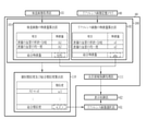
- the similarity calculation unit 60 includes a feature amount calculation unit 100, an individual similarity and total similarity calculation unit 110, and an attention area emphasis processing unit 111.
- the feature amount calculation unit 101 of the inspection image and the feature amount calculation unit 102 of the reference image calculate the feature amount of the image transmitted from the inspection image acquisition unit 55 and the reference image storage memory 80.
- the feature amount is preferably classified according to whether the observation target is located at at least one of the surface layer, the middle layer, and the deep layer. Further, the feature amount is preferably a value obtained from the shape and color of the observation target or those shapes and colors. Items of feature amount include, for example, blood vessel density, blood vessel shape, number of blood vessel branches, blood vessel thickness, blood vessel length, blood vessel tortuosity, blood vessel depth, glandular shape, and glandular opening shape. , The length of the blood vessel, the degree of tortuosity of the blood vessel, and the color information.
- the feature amount is preferably a value obtained by at least one of these or a combination of two or more of these.
- the item of the feature amount is not limited to this, and may be added as appropriate depending on the usage situation.
- the total feature amount of each endoscopic image calculated by the feature amount calculation unit 101 of the inspection image or the feature amount calculation unit 102 of the reference image is used as the total feature amount. As shown in FIG. 15, the total feature amount is transmitted to the attention area enhancement processing unit 111.
- the attention area enhancement processing unit 111 will be described later.
- the reference image and the individual feature amount related to this reference image are associated and stored in the reference image storage memory 80. May be good. Further, for the reference image for which the individual feature amount has been calculated in the past, the step of calculating the same individual feature amount may be skipped. This is to save the calculation area of the processor device 14.
- the value of the individual feature amount related to each inspection image calculated by the feature amount calculation unit 100 or each diagnosed reference image is transmitted to the individual similarity degree and the total similarity degree calculation unit 110. ..
- the individual similarity and total similarity calculation unit 110 relates to an inspection image which is a first illumination light image, a second illumination light image, or a superposed image, and a plurality of one or more types of diagnosed reference images. Compare individual feature quantities. The comparison of the individual feature quantities is performed between the first illumination light image and the diagnosed white light image, or between the second illumination light image and the diagnosed special light image, and the individual similarity between the images is performed. Calculate the degree. In the specific example of FIG. 15, the shape of the blood vessel on the surface layer according to the inspection image, the individual feature amount of the branch is A1, the individual feature amount of the uniformity of the blood vessel on the surface layer is A2, and so on, and the shape of the blood vessel on the surface layer according to the reference image.
- the individual feature amount of the branch is a1
- the individual feature amount of the uniformity of the blood vessels on the surface layer is a2, and so on
- the values related to the items of the individual feature amount are calculated for each of the inspection image and the reference image.
- the total features are calculated by summing them up.
- the total feature amount of the inspection image is calculated as ABC
- the total feature amount of the reference image is calculated as abc.
- the total feature amount is transmitted to the attention area highlighting processing unit 111, and is used in an analysis process for highlighting the attention area in each of the inspection image and the reference image.
- the individual feature amounts related to the items of each feature amount are transmitted to the individual similarity degree and the total similarity degree calculation unit 110.
- the values of A1 and a1 are compared with respect to the individual similarity related to the shape / branch of the blood vessel on the surface layer (denoted as “A1 vs a1” in FIG. 15), and the individual similarity is calculated to be ⁇ 1. is doing. Subsequently, the total sum of the individual similarity is calculated as the total similarity and transmitted to the reference image selection unit 61. In the specific example of FIG. 15, the total similarity between the inspection image and the reference image is calculated as a value of ⁇ , and this value is transmitted to the reference image selection unit 61.
- the similarity calculation unit 60 may be equipped with artificial intelligence using a Convolutional Neural Network or the like, and the total similarity may be calculated using the artificial intelligence.
- the similarity calculation unit 60 is configured by a learning model for similarity output by machine learning or the like, and the inspection image and the reference image stored in the reference image storage memory 80 are used as a learning model for similarity output. By inputting, it is preferable to output the total similarity for each reference image.
- the individual similarity and the total similarity are calculated between the superimposed image transmitted from the inspection image acquisition unit 55 and the superimposed image transmitted from the reference image storage memory 80. Will be done. If there is no diagnosed white light image for comparison with the first illumination light image or a diagnosed special light image for comparison with the second illumination light image, it is a reference image and has been diagnosed. The comparison is performed after color matching is performed with respect to the hue, color tone, etc. of the image so that the white light image or the diagnosed special light image can be compared with the first illumination light image or the second illumination light image.
- the reference image selection unit 61 receives one or a plurality of reference images and the total similarity calculated or output for each reference image from the similarity calculation unit 60. As shown in FIG. 16, the reference image selection unit 61 assigns a ranking to a plurality of reference images according to the total similarity. Subsequently, among the plurality of reference images, a reference image whose overall similarity satisfies a specific condition is selected and transmitted to the display control unit 62.
- the specific condition is a threshold value determined by the value of total similarity. This particular condition threshold is variable and can be set automatically or manually by the user. Specifically, a reference image having a total similarity higher than a certain value (threshold value) is selected and displayed.
- a reference image whose overall similarity is equal to or higher than a specific condition (greater than or equal to a threshold value) is selected as a reference image for display and transmitted to the display control unit 62.
- a reference image whose overall similarity is calculated to be ⁇ by comparison with an inspection image is transmitted to the reference image selection unit 61.
- the reference images whose total similarity is calculated to be 87, 95, 92, and 30, respectively, as shown in FIG. 16 are transmitted to the reference image selection unit 61.
- the reference image with an overall similarity of 95 is ranked first, the reference image with 92 is ranked second, the reference image with 87 is ranked third, and the reference image with a total similarity of 30 is ranked fourth.
- the specific condition is "total similarity is 31 or more”.
- the reference image having the total similarity of 30 does not satisfy a specific condition, it is not transmitted to the display control unit 62, the reference images having the total similarity of 95, 92, and 87 are selected, and the display control unit 62 is selected. Will be sent to.
- the reference image to be presented can be selected according to the value of the total similarity. For example, when a plurality of reference images are selected by the reference image selection unit 61 and the number of selected reference images is larger than expected by the user, the threshold value of the total similarity is increased to present only the reference images having higher similarity. can do.
- the attention area highlighting processing unit 111 performs the attention area highlighting process for highlighting the attention area in the inspection image or the reference image as marking according to the value of the total feature amount.
- the inspection image to which the attention area enhancement processing has been performed and the reference image to which the attention area enhancement processing has been performed are transmitted to the display control unit 62 and displayed on the display 15.
- the inspection image to which the attention area enhancement processing has been performed is simply referred to as an inspection image
- the reference image to which the attention area enhancement processing has been performed is also simply referred to as a reference image. It is not necessary to perform the attention area enhancement process.
- the inspection image or the reference image on which the marking of the region of interest is not displayed is transmitted to the display control unit 62 and displayed on the display 15.
- the display mode of the marking based on the attention area enhancement process As shown in FIG. 17, a circular frame and a reference numeral (inspection image: I1, reference image: R1) surrounding the attention area are shown. ..
- the marking display mode is not limited to this example, and the shape, color, size, and thickness can be appropriately changed. When there are a plurality of areas of interest, markings having different shapes, colors, sizes, thicknesses, etc. may be used for each area of interest. Symbols such as numbers and letters may be added to each marking. If the user is aware that the lesion is extremely sensitive, it may be displayed in yellow, red, or the like.
- the value of the total feature amount for displaying the marking is set by a threshold value set automatically or manually.
- the user can appropriately set whether or not to display the marking on each endoscope image displayed on the display 15. With the above configuration, the user can easily recognize the area of interest.
- the display control unit 62 makes the inspection image and the reference image selected by the reference image selection unit 61 into one screen, and displays them on the display 15 as the reference image presentation screen 120. Further, it is preferable to display the reference image, the diagnosis result of the reference image, the total similarity, and the ranking of the total similarity on one screen as the reference image presentation screen 120.
- a display example in the first embodiment is shown in FIG. In FIG. 17, the inspection image number, the inspection image type 121, the inspection image (in this case, the superimposed image) 123 in which the attention area is highlighted, the reference image number, the reference image type 122, and the attention area are highlighted on the display 15.
- the reference image (white light image) 124, the diagnosis result 125 of the reference image, and the overall similarity and the order 126 of the overall similarity are displayed.
- the user can improve the discrimination accuracy of the image diagnosis by comparing the inspection image with the diagnosed reference image. Further, it facilitates information transmission between the user and a third party who is observing the display 15 at the same time.
- the inspection image lacks information for comparison with the reference image (for example, the size of the area of interest in the screen, screen blur, brightness, focus). It is possible to urge the user in the above and prevent the inspection from being redone.
- the ranking switching icon 127 is displayed on the reference image presentation screen 120 as an operation icon for switching the displayed reference image 124 to a reference image having a higher or lower overall similarity.
- the order switching icon 127 is provided on the right side or the left side of the reference image 124.
- the order switching icon 127 is represented by a triangular icon and faces rightward or leftward.
- the shape and display mode of the order switching icon 127 are not limited to this.
- an image type switching icon 128 indicating that the types of the inspection image and the reference image can be switched is displayed on the upper side or the lower side of the inspection image 123 and the reference image 124.
- the image type switching icon 128 is represented by a triangle and faces upward or downward.
- the shape and display mode of the image type switching icon 128 are not limited to this.
- the user operates the ranking switching icon 127 or the image type switching icon 128 by using the mouse or touch panel of the UI 16.
- the UI 16 and the reference image presentation switch 12g may be combined and operated. For example, the user selects either the ranking switching icon 127 or the image type switching icon 128 via the mouse or touch panel of the UI 16, activates the selected icon, and then activates the reference image presentation switch. When you press 12g, the display corresponding to the activated icon is switched.
- the reference image presentation switch 12g is pressed after activating the rank switching icon 127 on the right side.
- the display of the diagnosis result of the reference image, the overall similarity and the ranking of the overall similarity is switched, and the screen shown in FIG. 18 is displayed. That is, the reference image presentation switch 12g can also function as a toggle switch for switching the display of the reference image.
- the order switching icon 127 on the right side is operated to switch the display to the reference image having a lower overall similarity, and the reference image presentation switch 12g is pressed faster (than normal pressing).
- the order switching icon 127 on the left side may be operated to switch the display to the reference image having the higher overall similarity.
- the endoscope 12 and UI 16 may be newly provided with a button for switching the order and a button for switching the display image.
- the image displayed as the inspection image 123 is a superimposed image
- the image displayed as the reference image 124 is a diagnosed white light image. ..
- the image that can be displayed on the display 15 as the inspection image 123 is at least one of the first illumination light image, the second illumination light image, and the superimposed image, and the image type switching icon 128 on the inspection image side is operated. Can be switched between each other.
- the image that can be displayed as the reference image 124 is a diagnosed image stored in the reference image storage memory 80, for example, a diagnosed white light image or a diagnosed special light image.
- By operating the image type switching icon 128 on the reference image side it is possible to switch between the diagnosed white light image and the diagnosed special light image.
- the operation method of the image type switching icon 128 on the inspection image side or the reference image side is the same as the operation method of the image type switching icon 128.
- the inspection image 123 being displayed is switched from the superimposed image to the second illumination light image.
- the image type switching icon 128 on the reference image side is operated, the displayed reference image 124 is switched from the white light image to the special light image.
- the special light image (second illumination light image) is set with the image type switching icon 128 on the inspection image side on the reference image presentation screen 120, the image type switching icon 128 on the reference image side does not have to be operated.
- the display may be automatically switched to the display of the reference image (special light image) captured by the same type of special light as the inspection image. In this case, it is preferable to be able to set to automatically switch the type of the reference image according to the type of the inspection image.
- a second illumination light image of a type that the user is not accustomed to is used as an inspection image. It may be displayed.
- the types of second illumination light increase, the user must learn how to distinguish subjects taken with all types of second illumination light, so depending on the type of second illumination light, the user may observe. It is assumed that you are not used to it. With the above configuration, it is possible to observe the reference image captured by using the same type of second illumination light as the type of second illumination light of the inspection image, so that it is easy to observe the type of second illumination light image that the user is not familiar with. Can be.
- the reference image selection unit 61 sends an instruction to display a warning to the display control unit 62.
- a warning is displayed on the reference image presentation screen 120.
- the frame showing the order of the total similarity and the total similarity may be displayed thicker than usual, and the warning display 130 may be used.
- the warning display 130 is not limited to this method. For example, you may change the color, size, and thickness of the overall similarity and the ranking of the overall similarity, and a warning message "The reference image does not exist" is displayed at the position where the reference image is normally displayed.
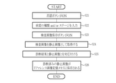
- step S11 When the reference image presentation switch 12g is pressed when the inspection image is acquired or is (step S11), the reference image presentation mode switching unit 56 is operated to switch to the reference image presentation mode (step S12).
- the inspection image and the diagnosed reference image stored in the reference image storage memory 80 are transmitted to the similarity calculation unit 60 (step S13, step S14), and the overall similarity between the inspection image and the reference image is achieved.
- the degree is calculated (step S15).
- a reference image satisfying a specific condition is selected by the reference image selection unit (step S16), and finally, the inspection image, the reference image satisfying the specific condition, and the total similarity between the images are obtained. , It is displayed on the display 15 as the reference image presentation screen 120 (step S17).
- the mode may be automatically switched to the reference image presentation mode.
- the detection of the region of interest is used as a trigger to automatically switch to the reference image presentation mode and display the inspection image and the reference image without pressing the reference image presentation switch 12g. Display on 15.
- the processing and the like after switching to the reference image presentation mode are the same as the processing and the like when manually switching by the reference image presentation switch 12g.
- the second embodiment describes a case where the inspection image saving button 150, the still image acquisition unit 63, and the diagnosis result input unit 64 are provided in order to save the inspection image as a reference image.
- FIG. 22 is displayed on the reference image presentation screen 120.
- the inspection image number, the inspection image type 121, the inspection image (superimposed image) 123 in which the region of interest is highlighted, the reference image number, and the reference are displayed as the reference image presentation screen 120 in the first embodiment.
- Form 142, inspection image save button 150, screenshot button 151, and treatment start button 152 are displayed.
- the user When the user recognizes that the diagnosis result of the reference image and the diagnosis result of the inspection image do not match and the rejection button 141 is pressed, the user inputs the diagnosis result related to the inspection image into the diagnosis result input form 142 through the UI 16. can do.
- the denial button 141 When the denial button 141 is pressed, the diagnosis result is input, and the inspection image save button 150 is pressed, the still image acquisition unit 63 acquires the inspection image as a still image, and the diagnosis result input unit 64 serves as a still image.
- the acquired inspection image, the feature amount, and the diagnosis result input by the user can be associated with each other and stored in the reference image storage memory 80 as a new diagnosed reference image.
- the still image acquisition instruction switch 12h may be used as a trigger for acquiring the inspection image.
- the denial button 141 is pressed, the diagnosis result is input to the diagnosis result input form 142, and then the inspection image save button 150 or the still image acquisition instruction switch 12h is pressed.
- the denial button 141 is pressed and the diagnosis result is input.
- the attention region I1 of the inspection image is different from the discrimination result (tumor type is Type 1 and tumor stage is Stage 1) related to the attention region R1 of the reference image, the user. If the judgment is made, pressing the denial button 141 enables input to the diagnosis result input form 142.
- the diagnosis result for example, the type of the tumor is Type 1 and the stage of the tumor is Stage 2 related to the region of interest I1 of the examination image diagnosed by the user is input and the examination image save button 150 is pressed, it is currently displayed.
- the examination image 123 is acquired as a still image and transmitted to the diagnosis result input unit 64, and in the diagnosis result input unit 64, the diagnosis result "the type of tumor is Type 1 and the stage of the tumor is Stage 2" is associated with the still image.
- the inspection image and the diagnosis result associated with the inspection image can be stored in the reference image storage memory 80 as a diagnosed reference image.
- AI Artificial Intelligence
- step S21 when the denial button 141 is pressed on the reference image presentation screen 120 (step S21), the diagnosis result is input to the diagnosis result input form 142 (step S22).
- step S23 when the inspection image save button 150 is pressed (step S23), the still image acquisition unit 63 acquires the inspection image as a still image (step S24).
- step S25 the diagnosis result input unit 64 associates the inspection image acquired as a still image with the diagnosis result input to the diagnosis result input form 142 (step S25).
- step S26 the still image that has been diagnosed due to the association of the diagnosis results is newly stored in the reference image storage memory 80 (step S26).
- the image displayed as the reference image by default on the reference image presentation screen 120 is a superimposed image. ..
- the image to be displayed as the reference image is at least one of a white light image (first illumination light image), a special light image (second illumination light image), and a superimposed image, and the reference image presentation switch 12g. It is preferable that they can be switched to each other by pressing.
- the screenshot button 151 is displayed on the reference image presentation screen 120.
- the reference image presentation screen 120 displayed on the display 15 can be acquired as a still image and saved in a memory (not shown).
- the reference image presentation screen 120 can be recorded on a storage medium such as an inspection recording system or an electronic medical record.
- case records can be easily collected during the examination.
- the treatment start button 152 is displayed on the reference image presentation screen 120.
- the treatment start time is recorded in a memory (not shown).
- the treatment start time can be recorded on a storage medium such as an inspection recording system or an electronic medical record. Further, when the inspection image is acquired as a still image, the time required for the treatment of the region of interest in the still image can be saved in association with the still image.
- the medical image processing apparatus of the present invention is applied to an endoscopic system that acquires an endoscopic image as a medical image, but various internal organs such as a capsule endoscope are applied. Needless to say, it is applicable to the spectroscopic system, and as other medical images, X-ray images, CT images, MR images, ultrasonic images, pathological images, PET (Positron Emission Tomography) images, etc.
- the medical image processing apparatus of the present invention can be applied to various medical imaging devices to be acquired.
- the hardware-like structure of the processing unit that executes various processes such as the illumination light image generation unit 55b, the superimposed image generation unit 55c, and the central control unit 70 includes various processors as shown below. Is. For various processors, the circuit configuration is changed after manufacturing the CPU (Central Processing Unit), FPGA (Field Programmable Gate Array), etc., which are general-purpose processors that execute software (programs) and function as various processing units. It includes a programmable logic device (PLD), which is a possible processor, a dedicated electric circuit, which is a processor having a circuit configuration specially designed for executing various processes, and the like.
- PLD programmable logic device
- One processing unit may be composed of one of these various processors, and may be composed of a combination of two or more processors of the same type or different types (for example, a plurality of FPGAs or a combination of a CPU and an FPGA). You may. Further, a plurality of processing units may be configured by one processor. As an example of configuring a plurality of processing units with one processor, first, as represented by a computer such as a client or a server, one processor is configured by a combination of one or more CPUs and software. There is a form in which this processor functions as a plurality of processing units.
- SoC System On Chip
- the various processing units are configured by using one or more of the above-mentioned various processors as a hardware-like structure.
- the hardware-like structure of these various processors is, more specifically, an electric circuit (circuitry) in which circuit elements such as semiconductor elements are combined.
- the hardware structure of the storage unit is a storage device such as an HDD (hard disk drive) or SSD (solid state drive).
Abstract
The present invention provides an endoscope system (10) and a method for operating the same, the endoscope system capable of displaying, on a display (15), multiple kinds of inspection images (123) based on multiple kinds of illumination light and a reference image (124) for comparison with each of the inspection images (123). An inspection image (123) obtained by capturing image of a subject under automatic switching between first illumination light and second illumination light and subjecting the images to superimposition processing, and diagnosed reference images are compared on the basis of feature amounts to calculate total similarities, a reference image (124) having a total similarity satisfying a specific condition is selected from among multiple reference images of which the total similarities are calculated, and the inspection image (123) and the selected reference image (124) are displayed.
Description
本発明は、検査画像と、診断済みのリファレンス画像のうち、検査画像との類似度が高いリファレンス画像を表示する内視鏡システム及びその作動方法に関する。
The present invention relates to an endoscopic system that displays an inspection image and a reference image having a high degree of similarity to the inspection image among the diagnosed reference images, and an operation method thereof.
医療分野においては、内視鏡画像等を用いて、患者の病状の診断や経過観察などの画像診断が行われている。このような画像診断に基づき、医師等は治療方針の決定などを行っている。しかしながら、医師などの画像診断を行う者の経験が浅い場合や、経験があっても、診断の対象となる画像が珍しい症例であり、専門性分野以外のものである場合には、医師が診断を確実に行うことが難しい場合がある。
In the medical field, image diagnosis such as diagnosis of a patient's medical condition and follow-up is performed using endoscopic images and the like. Based on such diagnostic imaging, doctors and others make decisions on treatment policies. However, if the person who performs the image diagnosis such as a doctor is inexperienced, or if the image to be diagnosed is a rare case even if he / she has experience, and the image is out of the field of specialization, the doctor diagnoses it. May be difficult to do reliably.
このような状況において、医師などの経験不足等を補うため、診断時に取得した診断時取得画像に合わせて、過去の症例の画像を用いることが行われている。例えば、特許文献1では、観察対象を撮像部で撮像して得られる第1の医用画像と、データベースに蓄積した第2の医用画像とを比較し、画像的特徴量の類似度の高い第2の医用画像を検索して、それら検索した第2の医用画像を表示装置に並べて表示している。
In such a situation, in order to make up for the lack of experience of doctors and the like, images of past cases are used in accordance with the images acquired at the time of diagnosis. For example, in Patent Document 1, a first medical image obtained by imaging an observation target with an imaging unit is compared with a second medical image stored in a database, and a second image feature having a high degree of similarity is compared. The medical images of the above are searched, and the searched second medical images are displayed side by side on the display device.
近年の内視鏡システムにおいては、特定の波長帯域を有する光を観察対象に照明して、観察対象上の病変部の視認性を向上することによって、病変部の検出をし易くすることが盛んに行われている。したがって、内視鏡診断においては、白色光により得られる白色光画像の他、特定の波長帯域を有する光により得られる特殊光画像が用いられつつある。また、特殊光画像については、近年の光源等の開発によって、種類が増えてきている傾向にある。
In recent endoscopic systems, it is popular to illuminate an observation target with light having a specific wavelength band to improve the visibility of the lesion on the observation target, thereby facilitating the detection of the lesion. It is done in. Therefore, in endoscopic diagnosis, in addition to the white light image obtained by white light, a special light image obtained by light having a specific wavelength band is being used. In addition, the types of special light images tend to increase due to the recent development of light sources and the like.
以上のような、白色光、及び、複数種類の特殊光については、検査中に都度切り替える操作を行うと、ユーザーに負担を強いることになることから、白色光、及び、複数種類の特殊光などの複数の照明光を自動的に切り替えて病変部などに照明し、それら白色光に基づく白色光画像、及び複数種類の特殊光に基づく特殊光画像を検査画像として提供することが好ましい。なお、特許文献1には、このように照明光の自動照明切替により複数種類の検査画像を取得し、各検査画像と、各検査画像との比較するためのリファレンス画像を合わせて表示することについては、記載されていない。
With regard to the white light and multiple types of special light as described above, if the operation of switching each time during the inspection is performed, it will impose a burden on the user. Therefore, the white light and multiple types of special light, etc. It is preferable to automatically switch a plurality of illumination lights of the above to illuminate a lesion or the like, and provide a white light image based on the white light and a special light image based on a plurality of types of special light as an inspection image. In addition, in Patent Document 1, a plurality of types of inspection images are acquired by automatic lighting switching of illumination light in this way, and each inspection image and a reference image for comparison with each inspection image are displayed together. Is not listed.
本発明は、複数種類の照明光の照明切替などによって、ユーザーに負担をかけることなく、複数種類の照明光に基づく複数種類の検査画像と、各検査画像とを比較するためのリファレンス画像とをディスプレイに表示することができる内視鏡システム及びその作動方法を提供することを目的とする。
The present invention provides a plurality of types of inspection images based on a plurality of types of illumination light and a reference image for comparing each inspection image without imposing a burden on the user by switching the illumination of a plurality of types of illumination light. It is an object of the present invention to provide an endoscopic system that can be displayed on a display and a method of operating the same.
本発明の内視鏡システムは、光源ユニットと、画像制御用プロセッサを備える。光源ユニットは、互いに発光スペクトルが異なる第1照明光と第2照明光とを発する。光源ユニットは、第1照明光を発光する第1照明期間と第2照明光を発光する第2照明期間とを自動的に切り替える場合において、第1照明光を第1発光パターンで発光し、第2照明光を第2発光パターンで発光する。画像制御用プロセッサは、第1照明光を被写体に照射して撮像した第1照明光画像、第2照明光を被写体に照射して撮像した第2照明光画像、及び、第2照明光画像を解析処理して得られた解析結果を第1照明光画像に重畳表示した重畳画像のうち少なくともいずれか1つを検査画像として取得し、検査画像とリファレンス画像とを特徴量に基づいて比較して総合類似度を算出し、診断済みのリファレンス画像を記憶するリファレンス画像記憶メモリを参照して、総合類似度が算出された複数のリファレンス画像のうち、総合類似度が特定の条件を満たすリファレンス画像を選択し、検査画像と、選択されたリファレンス画像とをディスプレイに表示する。
The endoscope system of the present invention includes a light source unit and an image control processor. The light source unit emits first illumination light and second illumination light having different emission spectra from each other. When the light source unit automatically switches between the first lighting period for emitting the first illumination light and the second illumination period for emitting the second illumination light, the light source unit emits the first illumination light in the first emission pattern, and the first emission pattern is used. 2 Illumination light is emitted in the second emission pattern. The image control processor captures the first illumination light image captured by irradiating the subject with the first illumination light, the second illumination light image captured by irradiating the subject with the second illumination light, and the second illumination light image. At least one of the superimposed images obtained by superimposing and displaying the analysis result obtained by the analysis processing on the first illumination light image is acquired as an inspection image, and the inspection image and the reference image are compared based on the feature amount. Refer to the reference image storage memory that calculates the total similarity and stores the diagnosed reference image, and among the plurality of reference images for which the total similarity has been calculated, the reference image whose total similarity satisfies a specific condition is selected. Select and display the inspection image and the selected reference image on the display.
画像制御用プロセッサは、リファレンス画像提示スイッチが押された後に、リファレンス画像の特徴量を算出し、検査画像及びリファレンス画像の特徴量に基づいて総合類似度が算出された上で、特定の条件を満たすリファレンス画像と検査画像とを表示することが好ましい。
After the reference image presentation switch is pressed, the image control processor calculates the feature amount of the reference image, calculates the total similarity based on the feature amount of the inspection image and the reference image, and then sets a specific condition. It is preferable to display the satisfying reference image and the inspection image.
リファレンス画像の表示は、総合類似度の順位にならって切り替えが可能であることが好ましい。検査画像として表示する画像は、重畳画像、第1照明光画像又は第2照明光画像の少なくともいずれか1つであり、互いに切り替えが可能であることが好ましい。リファレンス画像として表示する画像は、白色光画像又は特殊光画像のいずれか1つであり、互いに切り替えが可能であることが好ましい。
It is preferable that the display of the reference image can be switched according to the ranking of the overall similarity. The image to be displayed as an inspection image is at least one of a superimposed image, a first illumination light image, and a second illumination light image, and it is preferable that the images can be switched between each other. The image displayed as the reference image is either a white light image or a special light image, and it is preferable that the images can be switched between each other.
検査画像とリファレンス画像の特徴量の比較は、第1照明光画像と白色光画像との間、又は、第2照明光画像と特殊光画像との間で行うことが好ましい。特定の条件が満たされない場合に警告表示を行うことが好ましい。リファレンス画像を複数選択する場合、特定の条件を変更できることが好ましい。
It is preferable to compare the feature amounts of the inspection image and the reference image between the first illumination light image and the white light image, or between the second illumination light image and the special light image. It is preferable to display a warning when a specific condition is not met. When selecting a plurality of reference images, it is preferable that specific conditions can be changed.
検査画像を静止画として取得し、静止画をリファレンス画像としてリファレンス画像記憶メモリに保存できることが好ましい。静止画と、診断結果とを対応付け、新規の診断済みのリファレンス画像としてリファレンス画像記憶メモリに保存できることが好ましい。
It is preferable that the inspection image can be acquired as a still image and the still image can be saved as a reference image in the reference image storage memory. It is preferable that the still image and the diagnosis result can be associated with each other and saved in the reference image storage memory as a new diagnosed reference image.
検査画像及びリファレンス画像における、注目領域の診断結果を表示することが好ましい。
It is preferable to display the diagnosis result of the region of interest in the inspection image and the reference image.
検査画像及びリファレンス画像と同一の画面上に、総合類似度とリファレンス画像に対応付けた総合類似度の順位とをディスプレイに表示することが好ましい。検査画像とリファレンス画像を同一の画面上に表示し、かつ、検査画像が第2照明光画像である場合、検査画像を撮像した際に照射した第2照明光と同じ発光スペクトルの特殊光を照射して撮像されたリファレンス画像の表示に自動的に切り替えることが好ましい。画像制御用プロセッサは、解析処理によって、注目領域を検出した場合に、リファレンス画像の特徴量を算出し、特徴量に基づいて総合類似度が算出された上で、特定の条件を満たすリファレンス画像と検査画像とを表示することが好ましい。画像制御用プロセッサは、検査画像、及び、リファレンス画像記憶メモリに記憶されるリファレンス画像を、類似度出力用の学習モデルに入力することにより、リファレンス画像毎に、総合類似度を出力することが好ましい。
It is preferable to display the overall similarity and the ranking of the overall similarity associated with the reference image on the display on the same screen as the inspection image and the reference image. When the inspection image and the reference image are displayed on the same screen and the inspection image is the second illumination light image, special light having the same emission spectrum as the second illumination light emitted when the inspection image was imaged is irradiated. It is preferable to automatically switch to the display of the captured reference image. When the region of interest is detected by the analysis process, the image control processor calculates the feature amount of the reference image, calculates the total similarity based on the feature amount, and then sets the reference image to satisfy specific conditions. It is preferable to display the inspection image. It is preferable that the image control processor outputs the total similarity for each reference image by inputting the inspection image and the reference image stored in the reference image storage memory into the learning model for similarity output. ..
第1発光パターンは、第1照明期間のフレーム数が、それぞれの第1照明期間において同じである第1A発光パターンと、第1照明期間のフレーム数が、それぞれの第1照明期間において異なっている第1B発光パターンとのうちのいずれか1つであることが好ましい。第2発光パターンは、第2照明期間のフレーム数が、それぞれの第2照明期間において同じであり、且つ、第2照明光の発光スペクトルが、それぞれの第2照明期間において同じである第2Aパターン、第2照明期間のフレーム数が、それぞれの第2照明期間において同じであり、且つ、第2照明光の発光スペクトルが、それぞれの第2照明期間において異なっている第2Bパターン、第2照明期間のフレーム数が、それぞれの第2照明期間において異なっており、且つ、第2照明光の発光スペクトルが、それぞれの第2照明期間において同じである第2Cパターン、及び、第2照明期間のフレーム数が、それぞれの第2照明期間において異なっており、且つ、第2照明光の発光スペクトルが、それぞれの第2照明期間において異なっている第2Dパターンのうちのいずれか1つであることが好ましい。
In the first light emission pattern, the number of frames in the first lighting period is the same in each first lighting period, and the number of frames in the first lighting period is different in each first lighting period. It is preferably any one of the first B emission patterns. The second emission pattern is a second A pattern in which the number of frames in the second illumination period is the same in each second illumination period, and the emission spectrum of the second illumination light is the same in each second illumination period. The second B pattern, the second lighting period, in which the number of frames in the second lighting period is the same in each second lighting period and the emission spectrum of the second lighting period is different in each second lighting period. The number of frames is different in each second illumination period, and the emission spectrum of the second illumination light is the same in each second illumination period. The second C pattern and the number of frames in the second illumination period. However, it is preferable that the emission spectrum of the second illumination light is different from each other in each second illumination period, and the emission spectrum of the second illumination light is any one of the second D patterns different in each second illumination period.
本発明の内視鏡システムの作動方法は、互いに発光スペクトルが異なる第1照明光と第2照明光とを発する光源ユニットであって、第1照明光を発光する第1照明期間と第2照明光を発光する第2照明期間とを自動的に切り替える場合において、第1照明光を第1発光パターンで発光し、第2照明光を第2発光パターンで発光する光源ユニット、及び、画像制御用プロセッサを備える内視鏡システムの作動方法において、画像制御用プロセッサは、第1照明光を被写体に照射して撮像した第1照明光画像、第2照明光を被写体に照射して撮像した第2照明光画像、及び、第2照明光画像を解析処理して得られた解析結果を第1照明光画像に重畳表示した重畳画像のうち少なくともいずれか1つを検査画像として取得し、検査画像とリファレンス画像とを特徴量に基づいて比較して総合類似度を算出し、診断済みのリファレンス画像を記憶するリファレンス画像記憶メモリを参照して、総合類似度が算出された複数のリファレンス画像のうち、総合類似度が特定の条件を満たすリファレンス画像を選択し、検査画像と、選択されたリファレンス画像とをディスプレイに表示する。
The method of operating the endoscope system of the present invention is a light source unit that emits a first illumination light and a second illumination light having different emission spectra from each other, and a first illumination period and a second illumination that emit the first illumination light. A light source unit that emits the first illumination light in the first emission pattern and emits the second illumination light in the second emission pattern when automatically switching between the second illumination period that emits light, and for image control. In the method of operating the endoscope system including the processor, the image control processor irradiates the subject with the first illumination light and captures the first illumination light image, and irradiates the subject with the second illumination light and captures the image. At least one of the illumination light image and the superimposed image obtained by superimposing the analysis result obtained by analyzing the second illumination light image on the first illumination light image is acquired as an inspection image, and the inspection image is used. Of a plurality of reference images for which the total similarity has been calculated by comparing the reference image with the reference image based on the feature amount to calculate the total similarity and referring to the reference image storage memory for storing the diagnosed reference image. A reference image whose overall similarity satisfies a specific condition is selected, and the inspection image and the selected reference image are displayed on the display.
本発明によれば、複数種類の照明光の照明切替などによって、ユーザーに負担をかけることなく、複数種類の照明光に基づく複数種類の検査画像と、各検査画像とを比較するためのリファレンス画像とを表示することができる。
According to the present invention, a reference image for comparing a plurality of types of inspection images based on a plurality of types of illumination light with each inspection image without imposing a burden on the user by switching the illumination of the plurality of types of illumination light. And can be displayed.
[第1実施形態]
図1において、内視鏡システム10は、内視鏡12と、光源装置13と、プロセッサ装置14と、ディスプレイ15と、UI(User InterFace、ユーザーインターフェース)16とを有する。内視鏡12は、光源装置13と光学的に接続され、且つ、プロセッサ装置14と電気的に接続される。内視鏡12は、挿入部12a、操作部12b、湾曲部12c及び先端部12dを有している。挿入部12aは、観察対象の体内に挿入される。操作部12bは、挿入部12aの基端部分に設けられる。湾曲部12c及び先端部12dは、挿入部12aの先端側に設けられる。湾曲部12cは、操作部12bのアングルノブ12eを操作することにより湾曲動作する。先端部12dは、湾曲部12cの湾曲動作によって所望の方向に向けられる。 [First Embodiment]
In FIG. 1, theendoscope system 10 includes an endoscope 12, a light source device 13, a processor device 14, a display 15, and a UI (User InterFace) 16. The endoscope 12 is optically connected to the light source device 13 and electrically connected to the processor device 14. The endoscope 12 has an insertion portion 12a, an operation portion 12b, a bending portion 12c, and a tip portion 12d. The insertion portion 12a is inserted into the body to be observed. The operation portion 12b is provided at the base end portion of the insertion portion 12a. The curved portion 12c and the tip portion 12d are provided on the tip end side of the insertion portion 12a. The curved portion 12c bends by operating the angle knob 12e of the operating portion 12b. The tip portion 12d is directed in a desired direction by the bending motion of the bending portion 12c.
図1において、内視鏡システム10は、内視鏡12と、光源装置13と、プロセッサ装置14と、ディスプレイ15と、UI(User InterFace、ユーザーインターフェース)16とを有する。内視鏡12は、光源装置13と光学的に接続され、且つ、プロセッサ装置14と電気的に接続される。内視鏡12は、挿入部12a、操作部12b、湾曲部12c及び先端部12dを有している。挿入部12aは、観察対象の体内に挿入される。操作部12bは、挿入部12aの基端部分に設けられる。湾曲部12c及び先端部12dは、挿入部12aの先端側に設けられる。湾曲部12cは、操作部12bのアングルノブ12eを操作することにより湾曲動作する。先端部12dは、湾曲部12cの湾曲動作によって所望の方向に向けられる。 [First Embodiment]
In FIG. 1, the
また、操作部12bには、アングルノブ12e、観察モード切替スイッチ12f、リファレンス画像提示スイッチ12g及びズーム操作部12iが設けられている。観察モード切替スイッチ12fは、観察モードの切り替え操作に用いる。リファレンス画像提示スイッチ12gは、リファレンス画像の提示に用いる。静止画像取得指示スイッチ12hは、観察対象の静止画の取得指示に用いる。ズーム操作部12iは、ズームレンズ42の操作に用いる。
Further, the operation unit 12b is provided with an angle knob 12e, an observation mode changeover switch 12f, a reference image presentation switch 12g, and a zoom operation unit 12i. The observation mode changeover switch 12f is used for the observation mode changeover operation. The reference image presentation switch 12g is used for presenting the reference image. The still image acquisition instruction switch 12h is used for an instruction to acquire a still image to be observed. The zoom operation unit 12i is used to operate the zoom lens 42.
なお、内視鏡システム10は、観察モードとして、第1照明観察モード、第2照明観察モード及び重畳モードの3つのモードを有する。観察モード切替スイッチ12fを押すと、画像処理切替部54を介してモードが切り替わる。さらに、内視鏡システム10は、表示モードとして、検査画像表示モード及びリファレンス画像提示モードの2つのモードを有する。リファレンス画像提示スイッチ12gを押すと、リファレンス画像提示モード切替部56を介して表示モードが切り替わる。すなわち、本発明の内視鏡システムに搭載されるモードとしては、検査画像表示第1照明観察モード、検査画像表示第2照明観察モード、検査画像表示重畳モード、リファレンス画像提示第1照明観察モード、リファレンス画像表示第2照明観察モード及びリファレンス画像提示重畳モードの、計6つのモードが存在する。本段落以降、単に「検査画像表示モード」と記載してある際は、検査画像表示第1照明観察モード、検査画像表示第2照明観察モード、検査画像表示重畳モードのいずれかの3つのモードの場合すべてを指すが、デフォルトとしては、検査画像表示重畳モードを想定している。また、単に「リファレンス画像提示モード」と記載してある際は、リファレンス画像提示第1照明観察モード、リファレンス画像表示第2照明観察モード及びリファレンス画像提示重畳モードのいずれかの3つのモードの場合すべてを指すが、デフォルトとしては、リファレンス画像提示重畳モードを想定している。
The endoscope system 10 has three modes as observation modes: a first illumination observation mode, a second illumination observation mode, and a superimposition mode. When the observation mode changeover switch 12f is pressed, the mode is switched via the image processing changeover unit 54. Further, the endoscope system 10 has two display modes, an inspection image display mode and a reference image presentation mode. When the reference image presentation switch 12g is pressed, the display mode is switched via the reference image presentation mode switching unit 56. That is, as the modes mounted on the endoscope system of the present invention, the inspection image display first illumination observation mode, the inspection image display second illumination observation mode, the inspection image display superimposition mode, the reference image presentation first illumination observation mode, and the like. There are a total of six modes, a reference image display second illumination observation mode and a reference image presentation superimposition mode. From this paragraph onward, when the term "inspection image display mode" is simply used, there are three modes: inspection image display first illumination observation mode, inspection image display second illumination observation mode, and inspection image display superimposition mode. It refers to all cases, but as a default, the inspection image display superimposition mode is assumed. Further, when the term "reference image presentation mode" is simply described, all three modes of the reference image presentation first illumination observation mode, the reference image display second illumination observation mode, and the reference image presentation superimposition mode are used. However, as a default, the reference image presentation superimposition mode is assumed.
検査画像表示第1照明観察モード及びリファレンス画像提示第1照明観察モードでは、白色光などの通常光(第1照明光)を観察対象に照明して撮像することによって、自然な色合いの第1照明光画像を表示部としてのディスプレイ15に表示する。検査画像表示第2照明観察モード及びリファレンス画像提示第2照明観察モードでは、通常光と波長帯域が異なる特殊光(第2照明光)を観察対象に照明して撮像することによって、特定の構造を強調した第2照明光画像をディスプレイ15に表示する。検査画像表示重畳モード及びリファレンス画像提示重畳モードでは、発光スペクトルが異なる第1照明光と第2照明光とを切り替えて発光し、且つ、第1照明光に基づく画像に対して、ディスプレイ15に表示するための表示用画像とする処理を行い、一方、第2照明光に基づく画像に対して、AI(Artificial Intelligence)に関する処理、観察対象に関する特徴量等を得る処理などの解析処理を行う。解析処理の結果は、第1照明光画像に重畳表示される。また、検査画像表示モードでは、類似度算出部60内が、検査画像から個別特徴量の値及び総合特徴量の値を算出する。総合特徴量は注目領域強調処理部111又は表示制御部62に送信される。類似度算出部60については後述する(図15参照)。
Inspection image display In the first illumination observation mode and the reference image presentation first illumination observation mode, normal light such as white light (first illumination light) is illuminated on the observation target and imaged, so that the first illumination has a natural hue. The optical image is displayed on the display 15 as a display unit. Inspection image display In the second illumination observation mode and the reference image presentation second illumination observation mode, a specific structure is imaged by illuminating the observation target with special light (second illumination light) whose wavelength band is different from that of normal light. The emphasized second illumination light image is displayed on the display 15. In the inspection image display superimposition mode and the reference image presentation superimposition mode, the first illumination light and the second illumination light having different emission spectra are switched to emit light, and the image based on the first illumination light is displayed on the display 15. On the other hand, the image based on the second illumination light is subjected to analysis processing such as processing related to AI (Artificial Intelligence) and processing for obtaining feature quantities related to the observation target. The result of the analysis process is superimposed and displayed on the first illumination light image. Further, in the inspection image display mode, the similarity calculation unit 60 calculates the value of the individual feature amount and the value of the total feature amount from the inspection image. The total feature amount is transmitted to the attention area enhancement processing unit 111 or the display control unit 62. The similarity calculation unit 60 will be described later (see FIG. 15).
検査画像表示モードでは、観察モードの3態様において表示される画面をディスプレイ15に表示する。リファレンス画像提示モードでは、後述の通り、検査画像と特定の条件を満たすリファレンス画像を、リファレンス画像提示画面120として表示する。
In the inspection image display mode, the screen displayed in the three modes of the observation mode is displayed on the display 15. In the reference image presentation mode, as described later, the inspection image and the reference image satisfying a specific condition are displayed as the reference image presentation screen 120.
検査画像表示モード及びリファレンス画像提示モードにおいて、静止画像取得指示スイッチ12hをユーザーが操作することにより、静止画取得指示に関する信号が内視鏡12、光源装置13、及びプロセッサ装置14に送られる。検査画像表示モードにおいて静止画像取得指示スイッチ12hが押された場合、プロセッサ装置14では、第1照明期間もしくは第2照明期間、あるいはその両方において観察対象の静止画がメモリ(図示しない)に保存される。なお、リファレンス画像提示モードにおける静止画保存については、後に詳説する。
In the inspection image display mode and the reference image presentation mode, when the user operates the still image acquisition instruction switch 12h, a signal related to the still image acquisition instruction is sent to the endoscope 12, the light source device 13, and the processor device 14. When the still image acquisition instruction switch 12h is pressed in the inspection image display mode, the processor device 14 stores the still image to be observed in the memory (not shown) in the first lighting period, the second lighting period, or both. To. The still image storage in the reference image presentation mode will be described in detail later.
プロセッサ装置14は、ディスプレイ15及びUI16と電気的に接続される。ディスプレイ15は、観察対象の画像や、観察対象の画像に付帯する情報などを出力表示する。UI16は、キーボード、マウス、タッチパッド、マイク等を有し、機能設定などの入力操作を受け付ける機能を有する。プロセッサ装置14には、画像や画像情報などを記録するリファレンス画像記憶メモリ80が接続される(図2、図14参照)。なお、リファレンス画像記憶メモリ80は、Webシステム上のストレージであってもよい。また、プロセッサ装置14に外付けのメモリ(図示しない)を接続してもよい。
The processor device 14 is electrically connected to the display 15 and the UI 16. The display 15 outputs and displays an image to be observed, information incidental to the image to be observed, and the like. The UI 16 has a keyboard, a mouse, a touch pad, a microphone, and the like, and has a function of accepting input operations such as function settings. A reference image storage memory 80 for recording an image, image information, or the like is connected to the processor device 14 (see FIGS. 2 and 14). The reference image storage memory 80 may be a storage on the Web system. Further, an external memory (not shown) may be connected to the processor device 14.
図2において、光源装置13は、光源ユニット20と、光源ユニット20を制御する光源用プロセッサ21とを備える。光源ユニット20は、例えば、複数の半導体光源を有し、これらをそれぞれ点灯又は消灯し、点灯する場合には各半導体光源の発光量を制御することにより、観察対象を照明する照明光を発する。光源ユニット20は、V-LED(Violet Light Emitting Diode)20a、B-LED(Blue Light Emitting Diode)20b、G-LED(Green Light Emitting Diode)20c、及びR-LED(Red Light Emitting Diode)20dの4色のLEDを有する。
In FIG. 2, the light source device 13 includes a light source unit 20 and a light source processor 21 that controls the light source unit 20. The light source unit 20 has, for example, a plurality of semiconductor light sources, each of which is turned on or off, and when the light source unit 20 is turned on, the light emission amount of each semiconductor light source is controlled to emit illumination light for illuminating the observation target. The light source unit 20 is a V-LED (Violet Light Emitting Diode) 20a, a B-LED (Blue Light Emitting Diode) 20b, a G-LED (Green Light Emitting Diode) 20c, and an R-LED (Red Light Emitting Diode) 20d. It has 4 color LEDs.
図3に示すように、V-LEDは、中心波長405±10nm、波長範囲380~420nmの紫色光Vを発生する。B-LEDは、中心波長450±10nm、波長範囲420~500nmの青色光Bを発生する。G-LEDは、波長範囲が480~600nmに及ぶ緑色光Gを発生する。R-LEDは、中心波長620~630nmで、波長範囲が600~650nmに及ぶ赤色光Rを発生する。
As shown in FIG. 3, the V-LED generates purple light V having a center wavelength of 405 ± 10 nm and a wavelength range of 380 to 420 nm. The B-LED generates blue light B having a center wavelength of 450 ± 10 nm and a wavelength range of 420 to 500 nm. The G-LED produces green light G having a wavelength range of 480 to 600 nm. The R-LED produces red light R with a center wavelength of 620 to 630 nm and a wavelength range of 600 to 650 nm.
光源用プロセッサ21は、V-LED20a、B-LED20b、G-LED20c、及びR-LED20dを制御する。光源用プロセッサ21は、各LED20a~20dをそれぞれ独立に制御することで、紫色光V、青色光B、緑色光G、又は赤色光Rをそれぞれ独立に光量を変えて発光可能である。また、光源用プロセッサ21は、第1照明観察モード時には、紫色光V、青色光B、緑色光G、及び赤色光R間の光量比がVc:Bc:Gc:Rcとなる白色光を発光するように、各LED20a~20dを制御する。なお、Vc、Bc、Gc、Rc>0である。
The light source processor 21 controls the V-LED20a, B-LED20b, G-LED20c, and R-LED20d. By independently controlling each of the LEDs 20a to 20d, the light source processor 21 can emit purple light V, blue light B, green light G, or red light R by independently changing the amount of light. Further, the light source processor 21 emits white light having a light amount ratio of Vc: Bc: Gc: Rc among the purple light V, the blue light B, the green light G, and the red light R in the first illumination observation mode. As such, each LED 20a to 20d is controlled. In addition, Vc, Bc, Gc, Rc> 0.
なお、図4に示すように、第2照明光として、紫色光Vの光量を他の青色光B、緑色光G、及び赤色光Rの光量よりも大きくした第1特殊光を用いてもよい。また、図5に示すように、第2照明光として、緑色光Gの光量を、他の紫色光V、青色光B、及び赤色光Rの光量よりも大きくした第2特殊光を用いてもよい。
As shown in FIG. 4, as the second illumination light, the first special light in which the light amount of the purple light V is larger than the light amounts of the other blue light B, the green light G, and the red light R may be used. .. Further, as shown in FIG. 5, as the second illumination light, a second special light in which the light amount of the green light G is larger than the light amounts of the other purple light V, the blue light B, and the red light R may be used. good.
また、光源用プロセッサ21は、第2照明観察モード時には、短波長の狭帯域光としての紫色光V、青色光B、緑色光G、及び赤色光Rとの光量比がVk:Bs:Gs:Rsとなる特殊光を発光するように、各LED20a~20dを制御する。光量比Vs:Bs:Gs:Rsは、第1照明観察モード時に使用する光量比Vc:Bc:Gc:Rcと異なっており、観察目的に応じて適宜定められる。例えば、表層血管を強調する場合には、Vsを、他のBs、Gs、Rsよりも大きくすることが好ましく、中深層血管を強調する場合には、Gsを、他のVs、Gs、Rsよりも大きくすることが好ましい。
Further, in the second illumination observation mode, the light source processor 21 has a light amount ratio of Vk: Bs: Gs: purple light V, blue light B, green light G, and red light R as short-wavelength narrow-band light. Each LED 20a to 20d is controlled so as to emit special light that becomes Rs. The light amount ratio Vs: Bs: Gs: Rs is different from the light amount ratio Vc: Bc: Gc: Rc used in the first illumination observation mode, and is appropriately determined according to the observation purpose. For example, when emphasizing superficial blood vessels, it is preferable to make Vs larger than other Bs, Gs, Rs, and when emphasizing mesopelagic blood vessels, Gs is more than other Vs, Gs, Rs. It is also preferable to increase the size.
また、光源用プロセッサ21は、重畳モード時に、第1照明光と第2照明光とを自動的に切り替えて発光する場合において、第1照明光を第1発光パターンで発光し、第2照明光を第2発光パターンで発光する。具体的には、第1発光パターンは、図6に示すように、第1照明期間のフレーム数が、それぞれの第1照明期間において同じである第1A発光パターンと、図7に示すように、第1照明期間のフレーム数が、それぞれの第1照明期間において異なっている第1B発光パターンとのうちのいずれか1つであることが好ましい。
Further, the light source processor 21 emits the first illumination light in the first emission pattern when the first illumination light and the second illumination light are automatically switched and emitted in the superimposed mode, and the second illumination light is emitted. Is emitted in the second emission pattern. Specifically, as shown in FIG. 6, the first light emission pattern is the first A light emission pattern in which the number of frames in the first lighting period is the same in each first lighting period, and as shown in FIG. It is preferable that the number of frames in the first lighting period is any one of the first B emission patterns different in each first lighting period.
第2発光パターンは、図6に示すように、第2照明期間のフレーム数が、それぞれの第2照明期間において同じであり、且つ、第2照明光の発光スペクトルが、それぞれの第2照明期間において同じである第2Aパターン、図8示すように、第2照明期間のフレーム数が、それぞれの第2照明期間において同じであり、且つ、第2照明光の発光スペクトルが、それぞれの第2照明期間において異なっている第2Bパターン、図9に示すように、第2照明期間のフレーム数が、それぞれの第2照明期間において異なっており、且つ、第2照明光の発光スペクトルが、それぞれの第2照明期間において同じである第2Cパターン、図10に示すように、第2照明期間のフレーム数が、それぞれの第2照明期間において異なっており、且つ、第2照明光の発光スペクトルが、それぞれの第2照明期間において異なっている第2Dパターンのうちのいずれか1つであることが好ましい。なお、第1照明光の発光スペクトルは、それぞれの第1照明期間において同じであってもよく、異なってもよい。
In the second emission pattern, as shown in FIG. 6, the number of frames in the second illumination period is the same in each second illumination period, and the emission spectrum of the second illumination light is in each second illumination period. As shown in FIG. 8, the number of frames in the second illumination period is the same in each of the second illumination periods, and the emission spectrum of the second illumination light is the same in the second illumination. The second B pattern differs in the period, as shown in FIG. 9, the number of frames in the second illumination period is different in each second illumination period, and the emission spectrum of the second illumination light is the first. The second C pattern, which is the same in the two illumination periods, as shown in FIG. 10, the number of frames in the second illumination period is different in each second illumination period, and the emission spectrum of the second illumination light is different, respectively. It is preferably any one of the second D patterns that are different in the second illumination period of the above. The emission spectrum of the first illumination light may be the same or different in each first illumination period.
ここで、第1照明期間は第2照明期間よりも長くすることが好ましく、第1照明期間は2フレーム以上とすることが好ましい。例えば、図6では、第1発光パターンを第1Aパターンとし、第2発光パターンを第2Aパターン(第2照明期間のフレーム数:同じ、第2照明光の発光スペクトル:同じ)とする場合において、第1照明期間を2フレームとし、第2照明期間を1フレームとしている。第1照明光は、ディスプレイ15に表示する表示用画像の生成に用いられることから、第1照明光を観察対象に照明することによって、明るい画像が得られることが好ましい。
Here, the first lighting period is preferably longer than the second lighting period, and the first lighting period is preferably two frames or more. For example, in FIG. 6, when the first emission pattern is the first A pattern and the second emission pattern is the second A pattern (the number of frames in the second illumination period: the same, the emission spectrum of the second illumination light: the same), The first lighting period is set to 2 frames, and the second lighting period is set to 1 frame. Since the first illumination light is used to generate a display image to be displayed on the display 15, it is preferable to obtain a bright image by illuminating the observation target with the first illumination light.
第1照明光は、白色光であることが好ましい。一方、第2照明光は、解析処理に用いることから、第2照明光を観察対象に照明することによって、解析処理に適した画像が得られることが好ましい。例えば、血管深さが異なる複数の血管の形状情報に基づいて、解析処理を行う場合には、第2照明光として、紫色光V、青色光B、緑色光G、赤色光Rを用いることが好ましい。この場合、第2発光パターンを第2Aパターン(第2照明期間のフレーム数:同じ、第2照明光の発光スペクトル:同じ)又は第2Cパターン(第2照明期間のフレーム数:異なる、第2照明光の発光スペクトル:同じ)とする場合には、紫色光V、青色光B、緑色光G、赤色光Rのうちのいずれか1つの光を用いることが好ましい。一方、第2発光パターンを第2Bパターン(第2照明期間のフレーム数:同じ、第2照明光の発光スペクトル:異なる)又は第2Dパターン(第2照明期間のフレーム数:異なる、第2照明光の発光スペクトル:異なる)とする場合には、第2照明期間において、紫色光V、青色光B、緑色光G、赤色光Rのうち少なくとも2つの光を特定の順番で切り替えて発光することが好ましい。後述の図13では、紫色光V、緑色光G、及び赤色光Rの3つの光を、その順番で順次発光している。
The first illumination light is preferably white light. On the other hand, since the second illumination light is used for the analysis process, it is preferable to illuminate the observation target with the second illumination light to obtain an image suitable for the analysis process. For example, when performing analysis processing based on the shape information of a plurality of blood vessels having different blood vessel depths, purple light V, blue light B, green light G, and red light R may be used as the second illumination light. preferable. In this case, the second emission pattern is the second A pattern (the number of frames in the second illumination period: the same, the emission spectrum of the second illumination light: the same) or the second C pattern (the number of frames in the second illumination period: different, the second illumination). When the emission spectrum of light is the same), it is preferable to use any one of purple light V, blue light B, green light G, and red light R. On the other hand, the second emission pattern is the second B pattern (number of frames in the second illumination period: same, emission spectrum of the second illumination light: different) or the second D pattern (number of frames in the second illumination period: different, second illumination light). (Emission spectrum: different), at least two of purple light V, blue light B, green light G, and red light R may be switched in a specific order to emit light in the second illumination period. preferable. In FIG. 13, which will be described later, three lights, purple light V, green light G, and red light R, are sequentially emitted in that order.
ここで、第2照明光として、第1特殊光と第2特殊光の両方を用いる場合は、第2発光パターンを第2Bパターン又は第2Dパターンとして、第1特殊光と第2特殊光を交互に発光するようにしてもよい。
Here, when both the first special light and the second special light are used as the second illumination light, the first special light and the second special light are alternately used as the second emission pattern as the second B pattern or the second D pattern. It may be made to emit light.
なお、第1照明期間と第2照明期間の切替パターンである第1、2発光パターンの詳細については、撮像用プロセッサ44による撮像センサ43の撮像制御に基づいて定められることから、後述する。また、フレームとは、撮像センサ43において特定タイミングから信号読み出し完了までの間の期間を少なくとも含む期間の単位のことをいう。
The details of the first and second light emission patterns, which are the switching patterns between the first lighting period and the second lighting period, will be described later because they are determined based on the image pickup control of the image pickup sensor 43 by the image pickup processor 44. Further, the frame refers to a unit of a period including at least a period from a specific timing to the completion of signal reading in the image pickup sensor 43.
例えば、粘膜表面からの深さが50μmの範囲内にある表層血管、粘膜表面からの深さが200μmの範囲内にある中層血管、及び、粘膜表面からの深さが600μmの範囲内にある深層血管に関する血管の形状情報を取得し、これら表層、中層、深層の血管の形状情報に基づいて解析処理を行う場合には、表層血管を強調する紫色光V、中層血管を強調する緑色光G、深層血管を強調する赤色光Rを用いることが好ましい。
For example, superficial blood vessels having a depth of 50 μm from the mucosal surface, middle blood vessels having a depth of 200 μm from the mucosal surface, and deep blood vessels having a depth of 600 μm from the mucosal surface. When acquiring blood vessel shape information related to blood vessels and performing analysis processing based on the shape information of these surface, middle, and deep blood vessels, purple light V that emphasizes surface blood vessels, green light G that emphasizes middle layer blood vessels, and so on. It is preferable to use red light R that emphasizes deep blood vessels.
なお、本明細書において、光量比は、少なくとも1つの半導体光源の比率が0(ゼロ)の場合を含む。したがって、各半導体光源のいずれか1つ又は2つ以上が点灯しない場合を含む。例えば、紫色光V、青色光B、緑色光G、及び赤色光R間の光量比が1:0:0:0の場合のように、半導体光源の1つのみを点灯し、他の3つは点灯しない場合も、光量比を有するものとする。
In the present specification, the light intensity ratio includes the case where the ratio of at least one semiconductor light source is 0 (zero). Therefore, this includes the case where any one or more of the semiconductor light sources are not lit. For example, as in the case where the light amount ratio between purple light V, blue light B, green light G, and red light R is 1: 0: 0: 0, only one of the semiconductor light sources is turned on, and the other three are turned on. Even if it does not light up, it shall have a light intensity ratio.
図2に示すように、各LED20a~20dが発する光は、ミラーやレンズなどで構成される光路結合部22を介して、ライトガイド23に入射される。ライトガイド23は、内視鏡12及びユニバーサルコード(内視鏡12と、光源装置13及びプロセッサ装置14を接続するコード)に内蔵されている。ライトガイド23は、光路結合部22からの光を、内視鏡12の先端部12dまで伝搬する。
As shown in FIG. 2, the light emitted by each of the LEDs 20a to 20d is incident on the light guide 23 via the optical path coupling portion 22 composed of a mirror, a lens, or the like. The light guide 23 is built in the endoscope 12 and a universal cord (a cord connecting the endoscope 12, the light source device 13 and the processor device 14). The light guide 23 propagates the light from the optical path coupling portion 22 to the tip portion 12d of the endoscope 12.
内視鏡12の先端部12dには、照明光学系30aと撮像光学系30bが設けられている。照明光学系30aは照明レンズ31を有しており、ライトガイド23によって伝搬した照明光は照明レンズ31を介して観察対象に照射される。撮像光学系30bは、対物レンズ41、撮像センサ43を有している。照明光を照射したことによる観察対象からの光は、対物レンズ41及びズームレンズ42を介して撮像センサ43に入射する。これにより、撮像センサ43に観察対象の像が結像される。ズームレンズ42は観察対象を拡大するためのレンズであり、ズーム操作部12iを操作することによって、テレ端とワイド端と間を移動する。
An illumination optical system 30a and an image pickup optical system 30b are provided at the tip end portion 12d of the endoscope 12. The illumination optical system 30a has an illumination lens 31, and the illumination light propagated by the light guide 23 is applied to the observation target through the illumination lens 31. The image pickup optical system 30b has an objective lens 41 and an image pickup sensor 43. The light from the observation target due to the irradiation of the illumination light is incident on the image pickup sensor 43 via the objective lens 41 and the zoom lens 42. As a result, an image to be observed is formed on the image pickup sensor 43. The zoom lens 42 is a lens for enlarging the observation target, and moves between the telephoto end and the wide end by operating the zoom operation unit 12i.
撮像センサ43は、原色系のカラーセンサであり、青色カラーフィルタを有するB画素(青色画素)、緑色カラーフィルタを有するG画素(緑色画素)、及び、赤色カラーフィルタを有するR画素(赤色画素)の3種類の画素を備える。図11に示すように、青色カラーフィルタBFは、主として青色帯域の光、具体的には波長帯域が380~560nmの波長帯域の光を透過する。青色カラーフィルタBFの透過率は、波長460~470nm付近においてピークになる。緑色カラーフィルタはGF、主として緑色帯域の光、具体的には、460~620nmの波長帯域の光を透過する。赤色カラーフィルタRFは、主として赤色帯域の光、具体的には、580~760nmの波長帯域の光を透過する。
The image pickup sensor 43 is a primary color sensor, and is a B pixel (blue pixel) having a blue color filter, a G pixel (green pixel) having a green color filter, and an R pixel (red pixel) having a red color filter. It is equipped with three types of pixels. As shown in FIG. 11, the blue color filter BF mainly transmits light in the blue band, specifically, light in the wavelength band having a wavelength band of 380 to 560 nm. The transmittance of the blue color filter BF peaks in the vicinity of the wavelength of 460 to 470 nm. The green color filter transmits GF, mainly light in the green band, specifically, light in the wavelength band of 460 to 620 nm. The red color filter RF mainly transmits light in the red band, specifically, light in the wavelength band of 580 to 760 nm.
また、撮像センサ43は、CCD(Charge-Coupled Device)又はCMOS(Complementary Metal Oxide Semiconductor)であることが好ましい。撮像用プロセッサ44は、撮像センサ43を制御する。具体的には、撮像用プロセッサ44により撮像センサ43の信号読み出しを行うことによって、撮像センサ43から画像信号が出力される。第1照明観察モードでは、白色光が撮像センサ43に露光された状態で、撮像用プロセッサ44が信号読み出しを行うことにより、撮像センサ43のB画素からBc画像信号が出力され、G画素からGc画像信号が出力され、R画素からRc画像信号が出力される。第2照明観察モードでは、特殊光が撮像センサ43に露光された状態で、撮像用プロセッサ44が信号読み出しを行うことによって、撮像センサ43のB画素からBs画像信号が出力され、G画素からGs画像信号が出力され、R画素からRs画像信号が出力される。
Further, the image sensor 43 is preferably a CCD (Charge-Coupled Device) or a CMOS (Complementary Metal Oxide Semiconductor). The image pickup processor 44 controls the image pickup sensor 43. Specifically, the image signal is output from the image pickup sensor 43 by reading out the signal of the image pickup sensor 43 by the image pickup processor 44. In the first illumination observation mode, the image pickup processor 44 reads out the signal while the white light is exposed to the image pickup sensor 43, so that the Bc image signal is output from the B pixel of the image pickup sensor 43 and the Gc is output from the G pixel. The image signal is output, and the Rc image signal is output from the R pixel. In the second illumination observation mode, the image pickup processor 44 reads out the signal while the special light is exposed to the image pickup sensor 43, so that the Bs image signal is output from the B pixel of the image pickup sensor 43 and the Gs is output from the G pixel. The image signal is output, and the Rs image signal is output from the R pixel.
重畳モードでは、撮像用プロセッサ44は、図12に示すように、第1照明期間において第1照明光を撮像センサ43に露光させた状態で、信号読み出しを行うことにより、撮像センサ43から第1画像信号を出力させる。第1画像信号を出力する期間を第1撮像期間とする。第1画像信号には、B画素から出力されるB1画像信号、G画素から出力されるG1画像信号、及び、R画素から出力されるR1画像信号が含まれる。また、撮像用プロセッサ44は、第2照明期間において第2照明光を撮像センサ43に露光させた状態で、信号読み出しを行うことにより、撮像センサ43から第2画像信号を出力させる。第2画像信号を出力する期間を第1撮像期間とする。第2画像信号には、B画素から出力されるB2画像信号、G画素から出力されるG2画像信号、及び、R画素から出力されるR2画像信号が含まれる。
In the superimposition mode, as shown in FIG. 12, the image pickup processor 44 first reads out the signal from the image pickup sensor 43 in a state where the first illumination light is exposed to the image pickup sensor 43 during the first illumination period. Output an image signal. The period for outputting the first image signal is defined as the first imaging period. The first image signal includes a B1 image signal output from the B pixel, a G1 image signal output from the G pixel, and an R1 image signal output from the R pixel. Further, the image pickup processor 44 outputs a second image signal from the image pickup sensor 43 by performing signal readout in a state where the image pickup sensor 43 is exposed to the second illumination light during the second illumination period. The period for outputting the second image signal is defined as the first imaging period. The second image signal includes a B2 image signal output from the B pixel, a G2 image signal output from the G pixel, and an R2 image signal output from the R pixel.
図2に示すように、CDS/AGC(Correlated Double Sampling/Automatic Gain Control)回路46は、撮像センサ43から得られるアナログの画像信号に相関二重サンプリング(CDS)や自動利得制御(AGC)を行う。CDS/AGC回路45を経た画像信号は、A/D(Analog/Digital)コンバータ48により、デジタルの画像信号に変換される。A/D変換後のデジタル画像信号がプロセッサ装置14に入力される。
As shown in FIG. 2, the CDS / AGC (Correlated Double Sampling / Automatic Gain Control) circuit 46 performs correlated double sampling (CDS) and automatic gain control (AGC) on the analog image signal obtained from the image pickup sensor 43. .. The image signal that has passed through the CDS / AGC circuit 45 is converted into a digital image signal by the A / D (Analog / Digital) converter 48. The digital image signal after A / D conversion is input to the processor device 14.
本段落以降で記載するプロセッサ装置14の構成及び作動方法は、検査画像取得部55及び表示制御部62を介する検査画像の取得と表示に関して、検査画像表示モードと、リファレンス画像提示モードとにおいて共通である。
The configuration and operation method of the processor device 14 described in the following paragraphs are common to the inspection image display mode and the reference image presentation mode with respect to the acquisition and display of the inspection image via the inspection image acquisition unit 55 and the display control unit 62. be.
プロセッサ装置14においては、画像制御用プロセッサによって構成される中央制御部70によって、プログラム用メモリ内のプログラムが動作することによって、画像取得部50と、DSP(Digital Signal Processor)52と、ノイズ低減部53と、画像処理切替部54と、画像処理部58と、表示制御部62の機能が実現される。また、画像処理部58の機能実現に伴って、検査画像取得部55において、第1照明光画像生成部55aと、第2照明光画像生成部55bと、重畳画像生成部55cとの機能が実現される。なお、重畳モードにおいては、画像制御用プロセッサは、第1画像信号又は第2画像信号に基づいて画像処理を行い、ディスプレイ15に対する制御を行う。
In the processor device 14, the central control unit 70 configured by the image control processor operates the program in the program memory, so that the image acquisition unit 50, the DSP (Digital Signal Processor) 52, and the noise reduction unit are operated. The functions of the 53, the image processing switching unit 54, the image processing unit 58, and the display control unit 62 are realized. Further, with the realization of the functions of the image processing unit 58, the functions of the first illumination light image generation unit 55a, the second illumination light image generation unit 55b, and the superimposed image generation unit 55c are realized in the inspection image acquisition unit 55. Will be done. In the superimposition mode, the image control processor performs image processing based on the first image signal or the second image signal, and controls the display 15.
画像取得部50は、内視鏡12から入力されるカラー画像を取得する。カラー画像には、撮像センサ43のB画素、G画素、R画素から出力される青色信号(B画像信号)、緑色信号(G画像信号)、赤色信号(R画像信号)が含まれている。取得したカラー画像はDSP52に送信される。DSP52は、受信したカラー画像に対して、欠陥補正処理、オフセット処理、ゲイン補正処理、マトリクス処理、ガンマ変換処理、デモザイク処理、及びYC変換処理等の各種信号処理を行う。ノイズ低減部53は、DSP52でデモザイク処理等を施したカラー画像に対して、例えば移動平均法やメディアンフィルタ法等によるノイズ低減処理を施す。ノイズを低減したカラー画像は、画像処理切替部54に入力される。
The image acquisition unit 50 acquires a color image input from the endoscope 12. The color image includes a blue signal (B image signal), a green signal (G image signal), and a red signal (R image signal) output from the B pixel, the G pixel, and the R pixel of the image pickup sensor 43. The acquired color image is transmitted to the DSP 52. The DSP 52 performs various signal processing such as defect correction processing, offset processing, gain correction processing, matrix processing, gamma conversion processing, demosaic processing, and YC conversion processing on the received color image. The noise reduction unit 53 performs noise reduction processing by, for example, a moving average method, a median filter method, or the like on a color image that has been demosaic processed by DSP 52. The color image with reduced noise is input to the image processing switching unit 54.
ゲイン補正処理後の各色の画像信号には、色再現性を高めるマトリクス処理が施される。その後、ガンマ変換処理によって、カラー画像の明るさや彩度が整えられる。マトリクス処理後のカラー画像には、デモザイク処理(等方化処理,同時化処理とも言う)が施され、補間により各画素の欠落した色の信号を生成される。デモザイク処理によって、全画素がRGB各色の信号を有するようになる。DSP52は、デモザイク処理後のカラー画像にYC変換処理を施し、輝度信号Yと色差信号Cb及び色差信号Crをノイズ低減部53に出力する。
The image signal of each color after the gain correction processing is subjected to matrix processing to improve the color reproducibility. After that, the brightness and saturation of the color image are adjusted by the gamma conversion process. The color image after the matrix processing is subjected to demosaic processing (also referred to as isotropic processing and simultaneous processing), and a signal of the missing color of each pixel is generated by interpolation. By the demosaic processing, all the pixels have the signals of each color of RGB. The DSP 52 performs a YC conversion process on the color image after the demosaic process, and outputs the luminance signal Y, the color difference signal Cb, and the color difference signal Cr to the noise reduction unit 53.
なお、第2照明光として第1特殊光を用いた場合には、第2画像信号に対して、観察対象に含まれる正常部と異常部(病変部など)との色の差を拡張する色差拡張処理を行ってもよい。色差拡張処理済みの第2画像信号に対して、解析処理を行ってもよい。
When the first special light is used as the second illumination light, the color difference that expands the color difference between the normal part and the abnormal part (lesion part, etc.) included in the observation target with respect to the second image signal. Extended processing may be performed. Analysis processing may be performed on the second image signal which has undergone color difference expansion processing.
ノイズ低減部53は、DSP52でデモザイク処理等を施したカラー画像に対して、例えば移動平均法やメディアンフィルタ法等によるノイズ低減処理を施す。ノイズを低減したカラー画像は、画像処理切替部54に入力される。
The noise reduction unit 53 performs noise reduction processing by, for example, a moving average method, a median filter method, or the like on a color image that has been demosaic processed by DSP 52. The color image with reduced noise is input to the image processing switching unit 54.
画像処理切替部54は、設定されているモードによって、ノイズ低減部53からの画像信号の送信先を、検査画像取得部55内の、第1照明光画像生成部55aと、第2照明光画像生成部55bと、重畳画像生成部55cのいずれか1つに切り替える。具体的には、第1照明観察モードにセットされている場合には、ノイズ低減部53からの画像信号を第1照明光画像生成部55aに入力する。第2照明観察モードにセットされている場合には、ノイズ低減部53からの画像信号を第2照明光画像生成部55bに入力する。重畳モードにセットされている場合には、ノイズ低減部53からの画像信号を重畳画像生成部55cに入力する。
Depending on the set mode, the image processing switching unit 54 sets the transmission destination of the image signal from the noise reduction unit 53 to the first illumination light image generation unit 55a and the second illumination light image in the inspection image acquisition unit 55. Switch to either one of the generation unit 55b and the superimposed image generation unit 55c. Specifically, when the first illumination observation mode is set, the image signal from the noise reduction unit 53 is input to the first illumination light image generation unit 55a. When the second illumination observation mode is set, the image signal from the noise reduction unit 53 is input to the second illumination light image generation unit 55b. When the superimposition mode is set, the image signal from the noise reduction unit 53 is input to the superimposition image generation unit 55c.
第1照明光画像生成部55aは、入力した1フレーム分のRc画像信号、Gc画像信号、Bc画像信号に対して、第1照明光画像用画像処理を施す。第1照明光画像用画像処理には、3×3のマトリクス処理、階調変換処理、3次元LUT(Look Up Table)処理等の色変換処理、色彩強調処理、空間周波数強調等の構造強調処理が含まれる。第1照明光画像用画像処理が施されたRc画像信号、Gc画像信号、Bc画像信号は、第1照明光画像として表示制御部62に入力される。
The first illumination light image generation unit 55a performs image processing for the first illumination light image on the input Rc image signal, Gc image signal, and Bc image signal for one frame. The image processing for the first illumination optical image includes color conversion processing such as 3 × 3 matrix processing, gradation conversion processing, and 3D LUT (Look Up Table) processing, color enhancement processing, and structural enhancement processing such as spatial frequency enhancement. Is included. The Rc image signal, the Gc image signal, and the Bc image signal that have undergone image processing for the first illumination light image are input to the display control unit 62 as the first illumination light image.
第2照明光画像生成部55bは、入力した1フレーム分のRs画像信号、Gs画像信号、Bs画像信号に対して、第2照明光画像用画像処理を施す。第2照明光画像用画像処理には、3×3のマトリクス処理、階調変換処理、3次元LUT(Look Up Table)処理等の色変換処理、色彩強調処理、空間周波数強調等の構造強調処理が含まれる。第2照明光画像用画像処理が施されたRs画像信号、Gs画像信号、Bs画像信号は、第2照明光画像として表示制御部62に入力される。
The second illumination light image generation unit 55b performs image processing for the second illumination light image on the input Rs image signal, Gs image signal, and Bs image signal for one frame. The image processing for the second illumination optical image includes color conversion processing such as 3 × 3 matrix processing, gradation conversion processing, and 3D LUT (Look Up Table) processing, color enhancement processing, and structural enhancement processing such as spatial frequency enhancement. Is included. The Rs image signal, the Gs image signal, and the Bs image signal that have undergone image processing for the second illumination light image are input to the display control unit 62 as the second illumination light image.
重畳画像生成部55cは、入力した1フレーム分のR1画像信号、G1画像信号、B1画像信号に対して、上述と同様の第1照明光画像用画像処理を施す。第1照明光画像信号用画像処理が施されたR1画像信号、G1画像信号、B1画像信号は、表示用画像として使用される。また、重畳画像生成部55cは、入力した特定フレーム分のR2画像信号、G2画像信号、B2画像信号に対して、解析処理を行う。また、重畳画像生成部55cは、特徴量を算出した解析処理の結果である解析結果を重畳画像として表示させる表示制御処理を行う。
The superimposed image generation unit 55c performs the same image processing for the first illumination light image as described above on the input R1 image signal, G1 image signal, and B1 image signal for one frame. The R1 image signal, the G1 image signal, and the B1 image signal that have undergone image processing for the first illumination light image signal are used as display images. Further, the superimposed image generation unit 55c performs analysis processing on the input R2 image signal, G2 image signal, and B2 image signal for a specific frame. Further, the superimposed image generation unit 55c performs display control processing for displaying the analysis result, which is the result of the analysis processing for calculating the feature amount, as the superimposed image.
例えば、第1発光パターンを第1A発光パターンとし、第2発光パターンを第2Bパターン(第2照明期間のフレーム数:同じ、第2照明光の発光スペクトル:異なる)とする場合において、第1照明光として白色光Wを2フレーム分、第2照明光としての紫色光V、緑色光G、赤色光Rを、白色光Wの発光の間に、それぞれ1フレーム分だけ観察対象に照明する場合には、図13に示すように、白色光の照明により得られる第1画像信号に対して第1照明光画像用画像処理を施すことによって、重畳画像を得る。
For example, when the first emission pattern is the first A emission pattern and the second emission pattern is the second B pattern (the number of frames in the second illumination period: the same, the emission spectrum of the second illumination light: different), the first illumination When the white light W is illuminated for two frames as the light, and the purple light V, the green light G, and the red light R as the second illumination light are illuminated for one frame each during the emission of the white light W. As shown in FIG. 13, a superimposed image is obtained by performing image processing for a first illumination light image on a first image signal obtained by illumination with white light.
一方、紫色光Vの照明により得られる第2画像信号(R2画像信号、G2画像信号、B2画像信号)に対して解析処理を行って、解析結果Vを得る。同様にして、緑色光Gの照明により得られる第2画像信号(R2画像信号、G2画像信号、B2画像信号)に対して解析処理を行って、解析結果Gを得る。また、赤色光Rの照明により得られる第2画像信号(R2画像信号、G2画像信号、B2画像信号)に対して解析処理を行って、解析結果Rを得る。これら解析結果V、G、Rは、赤色光Rに関する解析処理が完了した後、一まとめにした解析結果Tとして、表示用画像に表示される。なお、解析結果V、G、Rは、それぞれ単独で表示用画像に表示してもよく、また、解析結果V、G、Rのうち少なくとも2つ組み合わせて得られる解析結果を、重畳画像としてもよい。
On the other hand, the analysis processing is performed on the second image signal (R2 image signal, G2 image signal, B2 image signal) obtained by the illumination of purple light V, and the analysis result V is obtained. Similarly, the second image signal (R2 image signal, G2 image signal, B2 image signal) obtained by the illumination of the green light G is subjected to analysis processing to obtain the analysis result G. Further, the second image signal (R2 image signal, G2 image signal, B2 image signal) obtained by the illumination of the red light R is subjected to analysis processing to obtain the analysis result R. These analysis results V, G, and R are displayed on the display image as a group of analysis results T after the analysis process for the red light R is completed. The analysis results V, G, and R may be displayed independently on the display image, or the analysis result obtained by combining at least two of the analysis results V, G, and R may be used as a superimposed image. good.
なお、解析処理としては、後述する類似度算出部60における検査画像の特徴量算出部101における特徴量の算出、及び、算出した解析結果を表示用画像に重畳表示するための重畳表示制御処理が含まれる。解析処理の結果が表示された重畳画像は、表示制御部62に入力される。なお、特徴量算出部100における解析処理の詳細については後述する。
As the analysis process, the feature amount calculation unit 101 of the inspection image in the similarity calculation unit 60, which will be described later, calculates the feature amount, and the superimposed display control process for superimposing the calculated analysis result on the display image is performed. included. The superimposed image on which the result of the analysis process is displayed is input to the display control unit 62. The details of the analysis process in the feature amount calculation unit 100 will be described later.
検査画像表示モードとリファレンス画像提示モードの両方において、表示制御部62は、画像処理部58から出力される画像をディスプレイ15に表示するための制御を行う。具体的には、表示制御部62は、第1照明光画像、第2照明光画像、又は、重畳画像を、ディスプレイ15においてフルカラーで表示可能にする映像信号に変換する。変換済みの映像信号はディスプレイ15に入力される。これにより、ディスプレイ15には第1照明光画像、第2照明光画像、又は、重畳画像が表示される。
In both the inspection image display mode and the reference image presentation mode, the display control unit 62 controls to display the image output from the image processing unit 58 on the display 15. Specifically, the display control unit 62 converts the first illumination light image, the second illumination light image, or the superimposed image into a video signal that can be displayed in full color on the display 15. The converted video signal is input to the display 15. As a result, the first illumination light image, the second illumination light image, or the superimposed image is displayed on the display 15.
第2照明光を発光する第2照明期間は、第1照明期間よりもフレーム数が少ないことから、光量制御値を大きくして光量を大きくしたとしても、光量が大きくなる時間は短時間且つ間欠的であるため、内視鏡の先端部12dの温度上昇は一時的で安全性が確保される。
Since the number of frames in the second lighting period for emitting the second illumination light is smaller than that in the first illumination period, even if the light amount control value is increased and the light amount is increased, the time for increasing the light amount is short and intermittent. Therefore, the temperature rise of the tip portion 12d of the endoscope is temporary and safety is ensured.
撮像用プロセッサ44は、第1照明期間において第1照明光が照明された観察対象を撮像センサ43で撮像させることにより、撮像センサ43から第1画像信号を出力する。撮像用プロセッサ44は、第2照明期間において第2照明光が照明された観察対象を撮像センサ43で撮像させることにより、撮像センサ43から第2画像信号を出力する。表示制御部62は、第1画像信号に基づく表示用画像に対して、第2画像信号に基づく解析処理により得られた解析結果を表示する重畳画像をディスプレイ15に表示する。
The image pickup processor 44 outputs the first image signal from the image pickup sensor 43 by causing the image pickup sensor 43 to take an image of the observation target illuminated by the first illumination light during the first illumination period. The image pickup processor 44 outputs a second image signal from the image pickup sensor 43 by causing the image pickup sensor 43 to take an image of the observation target illuminated by the second illumination light during the second illumination period. The display control unit 62 displays a superimposed image displaying the analysis result obtained by the analysis process based on the second image signal on the display 15 with respect to the display image based on the first image signal.
なお、第1実施形態においては、第1照明光に基づく第1画像信号は、表示用画像に用い、第2照明光に基づく第2画像信号は、解析処理にのみに用いて、ディスプレイ15への表示に用いていないが、第2画像信号についても、ディスプレイ15への表示に用いてもよい。この場合には、第1画像信号に基づく表示用画像と、第2画像信号に基づく表示用画像とを、ディスプレイ15に対して切り替えて表示することになる。第2画像信号に基づく画像のディスプレイ15への表示又は非表示については、UI16によって適宜設定できるようにすることが好ましい。
In the first embodiment, the first image signal based on the first illumination light is used for the display image, and the second image signal based on the second illumination light is used only for the analysis process to the display 15. Although it is not used for the display of, the second image signal may also be used for the display on the display 15. In this case, the display image based on the first image signal and the display image based on the second image signal are switched and displayed on the display 15. It is preferable that the display or non-display of the image based on the second image signal on the display 15 can be appropriately set by the UI 16.
本段落以降で、検査画像が取得された後の制御である、リファレンス画像提示モードについて開示する。リファレンス画像提示モードの概略を説明すると、図14の通り、検査画像取得部55で取得された検査画像は、類似度算出部60において、リファレンス画像記憶メモリ80を参照し、保存されている診断済みのリファレンス画像と、特徴量に基づいて比較され、結果として、総合類似度が算出される。次に、リファレンス画像選択部61において、総合類似度が特定の条件を満たすリファレンス画像が選択され、表示制御部62に送信される。具体的には、総合類似度が一定値以上よりも高いリファレンス画像を選択する。最終的に、検査画像と、特定の条件を満たすリファレンス画像とが、一画面にリファレンス画像提示画面120として表示され、ユーザーが視認できる状態になる。
In the following paragraphs, the reference image presentation mode, which is the control after the inspection image is acquired, will be disclosed. Explaining the outline of the reference image presentation mode, as shown in FIG. 14, the inspection image acquired by the inspection image acquisition unit 55 is stored in the similarity calculation unit 60 with reference to the reference image storage memory 80. It is compared with the reference image of the above based on the feature amount, and as a result, the total similarity is calculated. Next, the reference image selection unit 61 selects a reference image whose overall similarity satisfies a specific condition, and transmits the reference image to the display control unit 62. Specifically, a reference image having a total similarity higher than a certain value is selected. Finally, the inspection image and the reference image satisfying a specific condition are displayed on one screen as the reference image presentation screen 120, and are visible to the user.
以降、リファレンス画像提示モードについての詳細を説明する。リファレンス画像提示スイッチ12gが押されると、リファレンス画像提示モード切替部56を介し、検査画像表示第1照明観察モードからリファレンス画像提示第1照明観察モードに、検査画像表示第2照明観察モードからリファレンス画像提示第2照明観察モードに、検査画像表示重畳モードからリファレンス画像提示重畳モードに切り替わる。上記構成により、ユーザーの任意のタイミングで、リファレンス画像提示モードに切り替え、リファレンス画像を表示することができる。
Hereinafter, the details of the reference image presentation mode will be explained. When the reference image presentation switch 12g is pressed, the inspection image display first lighting observation mode is changed to the reference image presentation first lighting observation mode, and the inspection image display second lighting observation mode is changed to the reference image via the reference image presentation mode switching unit 56. The second illumination observation mode is switched from the inspection image display superimposition mode to the reference image presentation superimposition mode. With the above configuration, the reference image presentation mode can be switched to and the reference image can be displayed at any timing of the user.
リファレンス画像提示モードである場合、検査画像取得部55で取得された第1照明光画像、第2照明光画像又は重畳画像、もしくは、そのすべてが、類似度算出部60内の検査画像の特徴量算出部101に送信される。また、リファレンス画像記憶メモリ80から、複数の診断済みの白色光画像又は複数の診断済みの特殊光画像の両方、もしくは、その両方が送信される。なお、検査画像表示第2照明観察モード及び検査画像表示重畳モードにおいても、前述の通り、特定の構造を強調した第2照明光画像もしくは重畳画像を生成するため、検査画像取得部55から特徴量算出部100に画像が送信され、特徴量算出の解析処理を行う。
In the reference image presentation mode, the first illumination light image, the second illumination light image, or the superimposed image acquired by the inspection image acquisition unit 55, or all of them, are the feature quantities of the inspection image in the similarity calculation unit 60. It is transmitted to the calculation unit 101. Further, the reference image storage memory 80 transmits a plurality of diagnosed white light images, a plurality of diagnosed special light images, and / or both of them. In addition, also in the inspection image display second illumination observation mode and the inspection image display superimposition mode, as described above, in order to generate the second illumination light image or the superimposition image in which the specific structure is emphasized, the feature amount from the inspection image acquisition unit 55. The image is transmitted to the calculation unit 100, and the feature amount calculation is analyzed.
リファレンス画像記憶メモリ80には、診断済みの白色光画像及び診断済みの特殊光画像が保存されている。リファレンス画像記憶メモリ80に保存されている診断済みの白色光画像及び診断済みの特殊光画像は、教科書又はアトラスの画像、学会で基準として用いられる画像、症例報告又は論文で用いられた画像、ユーザーが登録した画像があり、この限りではない。診断済みの白色光画像及び診断済みの特殊光画像に対応付けされている診断結果としては、病変部もしくは正常部であること、活動期又は寛解期であること、国際疾病分類、UICC TNM(Union for International Cancer Control Tumor Lymph Nodes Metastasis)分類、TNM(Tumor Lymph Nodes Metastasis)分類、Dukes分類、その他の分類、診断基準、ガイドライン、教科書及びアトラスに基づく診断名、種類、タイプ(type)、進展度、ステージのいずれかひとつ以上を含むことが好ましい。
The reference image storage memory 80 stores a diagnosed white light image and a diagnosed special light image. The diagnosed white light image and the diagnosed special light image stored in the reference image storage memory 80 are an image of a textbook or an atlas, an image used as a reference in an academic society, an image used in a case report or a paper, and a user. There is an image registered by, and this is not the case. The diagnostic results associated with the diagnosed white light image and the diagnosed special light image include lesion or normal, active or remission, international disease classification, UICC TNM (Union). for International Cancer Control Tumor Nodes Metastasis) classification, TNM (Tumor Lymph Nodes Metastasis) classification, Dukes classification, other classifications, diagnostic criteria, guidelines, textbooks and atlas-based diagnostic names, types, types, progress, It is preferable to include any one or more of the stages.
類似度算出部60は、図15に示すように、特徴量算出部100、個別類似度及び総合類似度算出部110、注目領域強調処理部111を含む。
As shown in FIG. 15, the similarity calculation unit 60 includes a feature amount calculation unit 100, an individual similarity and total similarity calculation unit 110, and an attention area emphasis processing unit 111.
検査画像の特徴量算出部101及びリファレンス画像の特徴量算出部102は、図15に示す通り、検査画像取得部55及びリファレンス画像記憶メモリ80から送信された画像の特徴量を算出する。特徴量は、観察対象が表層、中層、深層の少なくともいずれか1つに位置するかによって分類されることが好ましい。また、特徴量は、観察対象の形状、色又はそれら形状や色などから得られる値であることが好ましい。特徴量の項目としては、例えば、血管密度、血管形状、血管の分岐数、血管の太さ、血管の長さ、血管の蛇行度、血管の深達度、腺管形状、腺管開口部形状、腺管の長さ、腺管の蛇行度、色情報である。特徴量はこれらの少なくともいずれか1つ、もしくは、これらの2以上を組み合わせた値であることが好ましい。なお、特徴量の項目については、この限りではなく、使用状況に応じて適宜追加されてもよい。
As shown in FIG. 15, the feature amount calculation unit 101 of the inspection image and the feature amount calculation unit 102 of the reference image calculate the feature amount of the image transmitted from the inspection image acquisition unit 55 and the reference image storage memory 80. The feature amount is preferably classified according to whether the observation target is located at at least one of the surface layer, the middle layer, and the deep layer. Further, the feature amount is preferably a value obtained from the shape and color of the observation target or those shapes and colors. Items of feature amount include, for example, blood vessel density, blood vessel shape, number of blood vessel branches, blood vessel thickness, blood vessel length, blood vessel tortuosity, blood vessel depth, glandular shape, and glandular opening shape. , The length of the blood vessel, the degree of tortuosity of the blood vessel, and the color information. The feature amount is preferably a value obtained by at least one of these or a combination of two or more of these. The item of the feature amount is not limited to this, and may be added as appropriate depending on the usage situation.
検査画像の特徴量算出部101又はリファレンス画像の特徴量算出部102によって算出された、各内視鏡画像に係る個別特徴量の総和を総合特徴量とすることが好ましい。総合特徴量は、図15に示す通り、注目領域強調処理部111に送信される。注目領域強調処理部111については後述する。
It is preferable that the total feature amount of each endoscopic image calculated by the feature amount calculation unit 101 of the inspection image or the feature amount calculation unit 102 of the reference image is used as the total feature amount. As shown in FIG. 15, the total feature amount is transmitted to the attention area enhancement processing unit 111. The attention area enhancement processing unit 111 will be described later.
なお、リファレンス画像記憶メモリ80に保存されているリファレンス画像の個別特徴量が算出された後、リファレンス画像と、このリファレンス画像に係る個別特徴量とを対応付けてリファレンス画像記憶メモリ80に保存してもよい。また、過去に個別特徴量が算出されたリファレンス画像は、同一の個別特徴量を算出する工程をスキップしてもよい。プロセッサ装置14の演算領域の節約のためである。
After the individual feature amount of the reference image stored in the reference image storage memory 80 is calculated, the reference image and the individual feature amount related to this reference image are associated and stored in the reference image storage memory 80. May be good. Further, for the reference image for which the individual feature amount has been calculated in the past, the step of calculating the same individual feature amount may be skipped. This is to save the calculation area of the processor device 14.
リファレンス画像提示モードである場合、特徴量算出部100によって算出された各検査画像又は各診断済みのリファレンス画像に係る個別特徴量の値は、個別類似度及び総合類似度算出部110に送信される。
In the reference image presentation mode, the value of the individual feature amount related to each inspection image calculated by the feature amount calculation unit 100 or each diagnosed reference image is transmitted to the individual similarity degree and the total similarity degree calculation unit 110. ..
個別類似度及び総合類似度算出部110は、第1照明光画像、第2照明光画像あるいは重畳画像である検査画像と、複数の、1種類又は複数種類の診断済みのリファレンス画像と、に係る個別特徴量の比較をおこなう。個別特徴量の比較は、第1照明光画像と診断済みの白色光画像との間、もしくは、第2照明光画像と診断済みの特殊光画像との間でおこない、それぞれの画像間における個別類似度を算出する。図15の具体例では、検査画像に係る表層の血管の形状・分岐の個別特徴量がA1、表層の血管の均一度の個別特徴量がA2…と、リファレンス画像に係る表層の血管の形状・分岐の個別特徴量がa1、表層の血管の均一度の個別特徴量がa2…と、検査画像とリファレンス画像のそれぞれについて、個別特徴量の項目に係る値が算出される。個別特徴量が算出されると、これらを総和した総合特徴量が算出される。図15の具体例では、検査画像の総合特徴量がABC、リファレンス画像の総合特徴量がabcと算出される。総合特徴量は注目領域強調処理部111に送信され、検査画像とリファレンス画像とのそれぞれに注目領域の強調表示を行う解析処理に使用される。さらに、各特徴量の項目に係る個別特徴量は個別類似度及び総合類似度算出部110に送信される。図15の具体例では、表層の血管の形状・分岐に係る個別類似度について、A1とa1の値を比較し(図15では「A1vs a1」と表記)、個別類似度がα1であると算出している。続いて、個別類似度の総和を総合類似度として算出し、リファレンス画像選択部61に送信する。図15の具体例では、当該検査画像と当該リファレンス画像との間の総合類似度はαβγという値として算出され、この値がリファレンス画像選択部61に送信される。
The individual similarity and total similarity calculation unit 110 relates to an inspection image which is a first illumination light image, a second illumination light image, or a superposed image, and a plurality of one or more types of diagnosed reference images. Compare individual feature quantities. The comparison of the individual feature quantities is performed between the first illumination light image and the diagnosed white light image, or between the second illumination light image and the diagnosed special light image, and the individual similarity between the images is performed. Calculate the degree. In the specific example of FIG. 15, the shape of the blood vessel on the surface layer according to the inspection image, the individual feature amount of the branch is A1, the individual feature amount of the uniformity of the blood vessel on the surface layer is A2, and so on, and the shape of the blood vessel on the surface layer according to the reference image. The individual feature amount of the branch is a1, the individual feature amount of the uniformity of the blood vessels on the surface layer is a2, and so on, and the values related to the items of the individual feature amount are calculated for each of the inspection image and the reference image. When the individual features are calculated, the total features are calculated by summing them up. In the specific example of FIG. 15, the total feature amount of the inspection image is calculated as ABC, and the total feature amount of the reference image is calculated as abc. The total feature amount is transmitted to the attention area highlighting processing unit 111, and is used in an analysis process for highlighting the attention area in each of the inspection image and the reference image. Further, the individual feature amounts related to the items of each feature amount are transmitted to the individual similarity degree and the total similarity degree calculation unit 110. In the specific example of FIG. 15, the values of A1 and a1 are compared with respect to the individual similarity related to the shape / branch of the blood vessel on the surface layer (denoted as “A1 vs a1” in FIG. 15), and the individual similarity is calculated to be α1. is doing. Subsequently, the total sum of the individual similarity is calculated as the total similarity and transmitted to the reference image selection unit 61. In the specific example of FIG. 15, the total similarity between the inspection image and the reference image is calculated as a value of αβγ, and this value is transmitted to the reference image selection unit 61.
なお、類似度算出部60に、Convolutional Neural Network等を用いた人工知能を搭載し、人工知能を用いて、総合類似度を算出してもよい。例えば、類似度算出部60は、機械学習等による類似度出力用の学習モデルで構成し、検査画像、及び、リファレンス画像記憶メモリ80に記憶されるリファレンス画像を、類似度出力用の学習モデルに入力することにより、リファレンス画像毎に、総合類似度を出力することが好ましい。
Note that the similarity calculation unit 60 may be equipped with artificial intelligence using a Convolutional Neural Network or the like, and the total similarity may be calculated using the artificial intelligence. For example, the similarity calculation unit 60 is configured by a learning model for similarity output by machine learning or the like, and the inspection image and the reference image stored in the reference image storage memory 80 are used as a learning model for similarity output. By inputting, it is preferable to output the total similarity for each reference image.
なお、リファレンス画像として重畳画像が存在する場合は、検査画像取得部55から送信された重畳画像と、リファレンス画像記憶メモリ80から送信された重畳画像との間で個別類似度及び総合類似度が算出される。また、第1照明光画像と比較するための診断済みの白色光画像、もしくは、第2照明光画像と比較するための診断済みの特殊光画像が存在しない場合は、リファレンス画像である診断済みの白色光画像もしくは診断済みの特殊光画像を、第1照明光画像又は第2照明光画像と比較できるように、画像の色相、色調等に関して色合わせを行なった上で比較を行う。
When a superimposed image exists as a reference image, the individual similarity and the total similarity are calculated between the superimposed image transmitted from the inspection image acquisition unit 55 and the superimposed image transmitted from the reference image storage memory 80. Will be done. If there is no diagnosed white light image for comparison with the first illumination light image or a diagnosed special light image for comparison with the second illumination light image, it is a reference image and has been diagnosed. The comparison is performed after color matching is performed with respect to the hue, color tone, etc. of the image so that the white light image or the diagnosed special light image can be compared with the first illumination light image or the second illumination light image.
リファレンス画像選択部61は、類似度算出部60から、1又は複数のリファレンス画像と、リファレンス画像毎に算出又は出力された総合類似度を受信する。リファレンス画像選択部61は、図16に示すように、総合類似度によって複数のリファレンス画像に順位を付与する。続いて、複数のリファレンス画像のうち、総合類似度が特定の条件を満たすリファレンス画像を選択し、表示制御部62に送信する。特定の条件とは、総合類似度の値によって決定される閾値である。この特定の条件となる閾値は変更可能であり、自動的もしくはユーザーにより手動的に設定される。具体的には、総合類似度が一定値(閾値)よりも高いリファレンス画像を選出し、表示するようにする。第1実施形態では、総合類似度が特定の条件以上(閾値以上)であるリファレンス画像が表示用のリファレンス画像として選択され、表示制御部62に送信される。具体的には、図15で、検査画像との比較により総合類似度がαβγと算出されたリファレンス画像が、リファレンス画像選択部61に送信される。ここでは、図16で示すような、総合類似度がそれぞれ87、95、92、30と算出されたリファレンス画像がリファレンス画像選択部61に送信されたとする。これらのリファレンス画像の中で順位付けを行うと、総合類似度が95のリファレンス画像が1位、92のリファレンス画像が2位、87のリファレンス画像が3位、30のリファレンス画像が4位と順位付けされる。ここで、特定の条件を「総合類似度が31以上」としたとする。この条件では、総合類似度が30のリファレンス画像は特定の条件を満たさないため、表示制御部62に送信されず、総合類似度が95、92、87のリファレンス画像は選択され、表示制御部62に送信される。上記構成により、提示するリファレンス画像を総合類似度の値によって取捨選択できる。例えば、リファレンス画像がリファレンス画像選択部61によって複数選択され、選択されたリファレンス画像がユーザーの想定よりも多い場合に、総合類似度の閾値を上げることで、より類似度が高いリファレンス画像のみを提示することができる。
The reference image selection unit 61 receives one or a plurality of reference images and the total similarity calculated or output for each reference image from the similarity calculation unit 60. As shown in FIG. 16, the reference image selection unit 61 assigns a ranking to a plurality of reference images according to the total similarity. Subsequently, among the plurality of reference images, a reference image whose overall similarity satisfies a specific condition is selected and transmitted to the display control unit 62. The specific condition is a threshold value determined by the value of total similarity. This particular condition threshold is variable and can be set automatically or manually by the user. Specifically, a reference image having a total similarity higher than a certain value (threshold value) is selected and displayed. In the first embodiment, a reference image whose overall similarity is equal to or higher than a specific condition (greater than or equal to a threshold value) is selected as a reference image for display and transmitted to the display control unit 62. Specifically, in FIG. 15, a reference image whose overall similarity is calculated to be αβγ by comparison with an inspection image is transmitted to the reference image selection unit 61. Here, it is assumed that the reference images whose total similarity is calculated to be 87, 95, 92, and 30, respectively, as shown in FIG. 16 are transmitted to the reference image selection unit 61. When ranking among these reference images, the reference image with an overall similarity of 95 is ranked first, the reference image with 92 is ranked second, the reference image with 87 is ranked third, and the reference image with a total similarity of 30 is ranked fourth. Be attached. Here, it is assumed that the specific condition is "total similarity is 31 or more". Under this condition, since the reference image having the total similarity of 30 does not satisfy a specific condition, it is not transmitted to the display control unit 62, the reference images having the total similarity of 95, 92, and 87 are selected, and the display control unit 62 is selected. Will be sent to. With the above configuration, the reference image to be presented can be selected according to the value of the total similarity. For example, when a plurality of reference images are selected by the reference image selection unit 61 and the number of selected reference images is larger than expected by the user, the threshold value of the total similarity is increased to present only the reference images having higher similarity. can do.
注目領域強調処理部111は、前述の通り、総合特徴量の値に応じて、検査画像又はリファレンス画像における注目領域をマーキングとして強調表示する注目領域強調処理を行う。注目領域強調処理済みの検査画像と、注目領域強調処理済みのリファレンス画像とは、表示制御部62に送信されて、ディスプレイ15に表示される。以下、注目領域強調処理済みの検査画像については単に検査画像と表記し、注目領域強調処理済みのリファレンス画像についても単にリファレンス画像と表記する。なお、注目領域強調処理については、行わなくともよい。この場合には、注目領域のマーキング等が表示されていない検査画像又はリファレンス画像が、表示制御部62に送信されて、ディスプレイ15に表示される。
As described above, the attention area highlighting processing unit 111 performs the attention area highlighting process for highlighting the attention area in the inspection image or the reference image as marking according to the value of the total feature amount. The inspection image to which the attention area enhancement processing has been performed and the reference image to which the attention area enhancement processing has been performed are transmitted to the display control unit 62 and displayed on the display 15. Hereinafter, the inspection image to which the attention area enhancement processing has been performed is simply referred to as an inspection image, and the reference image to which the attention area enhancement processing has been performed is also simply referred to as a reference image. It is not necessary to perform the attention area enhancement process. In this case, the inspection image or the reference image on which the marking of the region of interest is not displayed is transmitted to the display control unit 62 and displayed on the display 15.
なお、注目領域強調処理に基づくマーキングの表示態様の例としては、図17に示すように、注目領域を囲うような円形の枠と符号(検査画像:I1、リファレンス画像:R1)で示している。なお、マーキングの表示態様としてはこの例に限られず、形状、色、大きさ、太さを適宜変更可能である。注目領域が複数存在する場合、各注目領域によって異なる形状、色、大きさ、太さ等のマーキングを使用してもよい。各マーキングに数字や文字等の記号を付記してもよい。なお、病変が極めて要注意であることをユーザーに意識させる場合は、黄色や赤色等で表示させてもよい。また、マーキングを表示させる総合特徴量の値は自動的もしくは手動的に設定される閾値によって設定されることが好ましい。なお、ディスプレイ15に表示される各内視鏡画像にマーキングを表示するか否かは、ユーザーが適宜設定できる。上記構成により、ユーザーが注目領域を容易に認識できるようになる。
As an example of the display mode of the marking based on the attention area enhancement process, as shown in FIG. 17, a circular frame and a reference numeral (inspection image: I1, reference image: R1) surrounding the attention area are shown. .. The marking display mode is not limited to this example, and the shape, color, size, and thickness can be appropriately changed. When there are a plurality of areas of interest, markings having different shapes, colors, sizes, thicknesses, etc. may be used for each area of interest. Symbols such as numbers and letters may be added to each marking. If the user is aware that the lesion is extremely sensitive, it may be displayed in yellow, red, or the like. Further, it is preferable that the value of the total feature amount for displaying the marking is set by a threshold value set automatically or manually. The user can appropriately set whether or not to display the marking on each endoscope image displayed on the display 15. With the above configuration, the user can easily recognize the area of interest.
表示制御部62は、検査画像と、リファレンス画像選択部61で選択されたリファレンス画像とを一画面にし、リファレンス画像提示画面120としてディスプレイ15に表示する。また、リファレンス画像と、リファレンス画像の診断結果と、総合類似度と、総合類似度の順位とを、リファレンス画像提示画面120として一画面に表示することが好ましい。第1実施形態における表示例を図17に示す。図17では、ディスプレイ15に検査画像ナンバー、検査画像の種類121、注目領域が強調表示された検査画像(この場合は重畳画像)123、リファレンス画像ナンバー、リファレンス画像の種類122、注目領域が強調表示されたリファレンス画像(白色光画像)124、リファレンス画像の診断結果125、総合類似度及び総合類似度の順位126が表示されている。上記構成により、ユーザーが、検査画像と診断済みのリファレンス画像を比較することで画像診断の鑑別精度を向上させることが可能になる。さらに、ユーザーと、ディスプレイ15を同時に観察している第三者との情報伝達を容易にする。また、検査画像中にリファレンス画像と比較するための情報(例えば、注目領域の画面中における大きさ、画面のブレ、明るさ、フォーカス)が不足しているかどうかの気づきを、内視鏡検査中においてユーザーに促すことができ、検査のやり直しを防止することができる。
The display control unit 62 makes the inspection image and the reference image selected by the reference image selection unit 61 into one screen, and displays them on the display 15 as the reference image presentation screen 120. Further, it is preferable to display the reference image, the diagnosis result of the reference image, the total similarity, and the ranking of the total similarity on one screen as the reference image presentation screen 120. A display example in the first embodiment is shown in FIG. In FIG. 17, the inspection image number, the inspection image type 121, the inspection image (in this case, the superimposed image) 123 in which the attention area is highlighted, the reference image number, the reference image type 122, and the attention area are highlighted on the display 15. The reference image (white light image) 124, the diagnosis result 125 of the reference image, and the overall similarity and the order 126 of the overall similarity are displayed. With the above configuration, the user can improve the discrimination accuracy of the image diagnosis by comparing the inspection image with the diagnosed reference image. Further, it facilitates information transmission between the user and a third party who is observing the display 15 at the same time. In addition, during endoscopy, we are aware of whether the inspection image lacks information for comparison with the reference image (for example, the size of the area of interest in the screen, screen blur, brightness, focus). It is possible to urge the user in the above and prevent the inspection from being redone.
リファレンス画像提示画面120において、デフォルトでは最も総合類似度の順位が高いリファレンス画像124が表示される。表示中のリファレンス画像124を、総合類似度が上位又は下位のリファレンス画像に切り替えるための操作用アイコンとして、順位切り替え用アイコン127がリファレンス画像提示画面120に表示されている。順位切り替え用アイコン127は、リファレンス画像124の右側又は左側に設けられている。順位切り替え用アイコン127は三角形のアイコンで表され、右方向又は左方向に向いている。左側の順位切り替え用アイコン127(図18参照)を操作することで、総合類似度が上位のリファレンス画像に切り替わる。一方、右側の順位切り替え用アイコン127を操作することで、総合類似度が下位のリファレンス画像に切り替わる。なお、順位切り替え用アイコン127の形状や表示態様はこの限りではない。
On the reference image presentation screen 120, the reference image 124 having the highest overall similarity is displayed by default. The ranking switching icon 127 is displayed on the reference image presentation screen 120 as an operation icon for switching the displayed reference image 124 to a reference image having a higher or lower overall similarity. The order switching icon 127 is provided on the right side or the left side of the reference image 124. The order switching icon 127 is represented by a triangular icon and faces rightward or leftward. By operating the ranking switching icon 127 (see FIG. 18) on the left side, the overall similarity is switched to the higher reference image. On the other hand, by operating the order switching icon 127 on the right side, the overall similarity is switched to the lower reference image. The shape and display mode of the order switching icon 127 are not limited to this.
また、リファレンス画像提示画面120においては、検査画像123とリファレンス画像124の上側又は下側には、検査画像及びリファレンス画像の種類を切り替え可能であることを示す画像種類切替用アイコン128が表示されている。画像種類切替用アイコン128は三角形で表され、上方向又は下方向に向いている。なお、画像種類切替用アイコン128の形状や表示態様はこの限りではない。
Further, on the reference image presentation screen 120, an image type switching icon 128 indicating that the types of the inspection image and the reference image can be switched is displayed on the upper side or the lower side of the inspection image 123 and the reference image 124. There is. The image type switching icon 128 is represented by a triangle and faces upward or downward. The shape and display mode of the image type switching icon 128 are not limited to this.
順位切り替え用アイコン127又は画像種類切替用アイコン128に対する操作は、UI16のマウスやタッチパネルなどを用いてユーザーが操作することが好ましい。また、UI16とリファレンス画像提示スイッチ12gとを組み合わせて操作してもよい。例えば、ユーザーが、UI16のマウスやタッチパネルを介して、順位切り替え用アイコン127又は画像種類切替用アイコン128のいずれか1つを選択し、選択済みのアイコンをアクティブにした上で、リファレンス画像提示スイッチ12gを押すと、アクティブにしたアイコンに対応する表示が切り替わる。
It is preferable that the user operates the ranking switching icon 127 or the image type switching icon 128 by using the mouse or touch panel of the UI 16. Further, the UI 16 and the reference image presentation switch 12g may be combined and operated. For example, the user selects either the ranking switching icon 127 or the image type switching icon 128 via the mouse or touch panel of the UI 16, activates the selected icon, and then activates the reference image presentation switch. When you press 12g, the display corresponding to the activated icon is switched.
順位切り替え用アイコン127を用いるリファレンス画像の切り替えについて、以下説明する。例えば、図17に示すように、総合類似度の順位が1位のリファレンス画像124が表示されている場合において、右側の順位切り替え用アイコン127をアクティブにした上でリファレンス画像提示スイッチ12gを押すと、総合類似度が2位のリファレンス画像に切り替わる他、リファレンス画像の診断結果、総合類似度及び総合類似度の順位の表示が切り替わり、図18に示す画面が表示される。すなわち、リファレンス画像提示スイッチ12gは、リファレンス画像の表示を切り替えるトグルスイッチとしても機能させることができる。
The switching of the reference image using the ranking switching icon 127 will be described below. For example, as shown in FIG. 17, when the reference image 124 having the highest overall similarity rank is displayed, the reference image presentation switch 12g is pressed after activating the rank switching icon 127 on the right side. In addition to switching to the reference image having the second highest overall similarity, the display of the diagnosis result of the reference image, the overall similarity and the ranking of the overall similarity is switched, and the screen shown in FIG. 18 is displayed. That is, the reference image presentation switch 12g can also function as a toggle switch for switching the display of the reference image.
なお、ユーザー設定により、順位切り替え用アイコン127のみをアクティブにすることも可能である。この場合には、UI16による順位切り替え用アイコン127をアクティブにする操作は不要である。例えば、リファレンス画像提示スイッチ12gの普通押しにより、右側の順位切り替え用アイコン127を操作して、総合類似度が下位のリファレンス画像に表示を切り替え、リファレンス画像提示スイッチ12gの早押し(普通押しよりも短い間隔での押圧操作)により、左側の順位切り替え用アイコン127を操作して、総合類似度が上位のリファレンス画像に表示を切り替えるようにしてもよい。
It is also possible to activate only the ranking switching icon 127 by user settings. In this case, the operation of activating the order switching icon 127 by the UI 16 is unnecessary. For example, by pressing the reference image presentation switch 12g normally, the order switching icon 127 on the right side is operated to switch the display to the reference image having a lower overall similarity, and the reference image presentation switch 12g is pressed faster (than normal pressing). By (pressing operation at short intervals), the order switching icon 127 on the left side may be operated to switch the display to the reference image having the higher overall similarity.
なお、内視鏡12やUI16に、新たに順位切り替え用ボタンや表示画像切り替え用ボタンを設けてもよい。上記構成により、ユーザーが、診断済みのリファレンス画像を見比べることができ、診断精度を向上させることが可能になる。さらに、ユーザーが経験した症例に類似の症例を収集しやすくすることができる。
Note that the endoscope 12 and UI 16 may be newly provided with a button for switching the order and a button for switching the display image. With the above configuration, the user can compare the diagnosed reference images and improve the diagnostic accuracy. Furthermore, it is possible to facilitate the collection of cases similar to the cases experienced by the user.
画像種類切替用アイコン128を用いる検査画像の切り替えについて、以下説明する。例えば、図17に示すように、リファレンス画像提示画面120において、デフォルトでは、検査画像123として表示される画像は重畳画像であり、リファレンス画像124として表示される画像は診断済みの白色光画像である。
The switching of inspection images using the image type switching icon 128 will be described below. For example, as shown in FIG. 17, on the reference image presentation screen 120, by default, the image displayed as the inspection image 123 is a superimposed image, and the image displayed as the reference image 124 is a diagnosed white light image. ..
検査画像123としてディスプレイ15に表示可能な画像は、第1照明光画像、第2照明光画像もしくは重畳画像の少なくともいずれか1つであり、検査画像側の画像種類切替用アイコン128を操作することによって、互いに切り替えが可能である。また、リファレンス画像124として表示可能な画像は、リファレンス画像記憶メモリ80に記憶されている診断済みの画像、例えば、診断済みの白色光画像もしくは診断済みの特殊光画像である。リファレンス画像側の画像種類切替用アイコン128を操作することによって、診断済みの白色光画像もしくは診断済みの特殊光画像を互いに切り替えが可能である。なお、検査画像側又はリファレンス画像側の画像種類切替用アイコン128の操作方法については、画像種類切替用アイコン128の操作方法と同様である。
The image that can be displayed on the display 15 as the inspection image 123 is at least one of the first illumination light image, the second illumination light image, and the superimposed image, and the image type switching icon 128 on the inspection image side is operated. Can be switched between each other. The image that can be displayed as the reference image 124 is a diagnosed image stored in the reference image storage memory 80, for example, a diagnosed white light image or a diagnosed special light image. By operating the image type switching icon 128 on the reference image side, it is possible to switch between the diagnosed white light image and the diagnosed special light image. The operation method of the image type switching icon 128 on the inspection image side or the reference image side is the same as the operation method of the image type switching icon 128.
例えば、図17に示すように、検査画像123として重畳画像が、リファレンス画像124として白色光画像が表示されている場合において、検査画像側の画像種類切替用アイコン128を操作すると、図19に示すように、表示中の検査画像123が、重畳画像から第2照明光画像に切り替わる。また、リファレンス画像側の画像種類切替用アイコン128を操作すると、表示中のリファレンス画像124が、白色光画像から特殊光画像に切り替わる。上記構成により、ユーザーが希望する内視鏡画像の種類で、検査画像とリファレンス画像とを比較することができる。加えて、リファレンス画像として白色光画像もしくは特殊光画像のどちらかのみが存在する場合における、検査画像とリファレンス画像との比較においても上記構成は有用である。
For example, as shown in FIG. 17, when the superimposed image is displayed as the inspection image 123 and the white light image is displayed as the reference image 124, when the image type switching icon 128 on the inspection image side is operated, it is shown in FIG. As described above, the inspection image 123 being displayed is switched from the superimposed image to the second illumination light image. Further, when the image type switching icon 128 on the reference image side is operated, the displayed reference image 124 is switched from the white light image to the special light image. With the above configuration, it is possible to compare the inspection image and the reference image with the type of endoscopic image desired by the user. In addition, the above configuration is also useful in the comparison between the inspection image and the reference image when only either the white light image or the special light image is present as the reference image.
リファレンス画像提示画面120において、検査画像側の画像種類切替用アイコン128で特殊光画像(第2照明光画像)に設定した場合には、リファレンス画像側の画像種類切替用アイコン128を操作しなくとも、自動的に、検査画像と同じ種類の同じ種類の特殊光で撮像したリファレンス画像(特殊光画像)の表示に自動的に切り替えるようにしてもよい。なお、この場合、検査画像の種類に合わせてリファレンス画像の種類を自動的に切り替える設定ができるとよい。上記構成により、ユーザーが使い慣れていない特殊光画像を観察する場合においても、リファレンス画像と見比べることで着目すべき領域を把握し、鑑別を行いやすくすることができる。本願発明の内視鏡システムでは、複数種類の第2照明光を自動的に切り替えて被写体を撮像することを想定しているため、ユーザーが使い慣れていない種類の第2照明光画像が検査画像として表示される場合がある。また、第2照明光の種類が増えると、ユーザーはあらゆる第2照明光の種類で撮影された被写体の鑑別方法を習得しなければならないため、第2照明光の種類によっては、ユーザーが観察に慣れていないことが想定される。上記構成により、検査画像の第2照明光の種類と同じ種類の第2照明光を用いて撮像されたリファレンス画像を観察できるため、ユーザーが見慣れていない種類の第2照明光画像の観察を容易にすることができる。
When the special light image (second illumination light image) is set with the image type switching icon 128 on the inspection image side on the reference image presentation screen 120, the image type switching icon 128 on the reference image side does not have to be operated. , The display may be automatically switched to the display of the reference image (special light image) captured by the same type of special light as the inspection image. In this case, it is preferable to be able to set to automatically switch the type of the reference image according to the type of the inspection image. With the above configuration, even when observing a special light image that the user is not accustomed to using, it is possible to grasp the area of interest by comparing it with the reference image and facilitate the discrimination. Since the endoscope system of the present invention assumes that a plurality of types of second illumination lights are automatically switched to capture a subject, a second illumination light image of a type that the user is not accustomed to is used as an inspection image. It may be displayed. In addition, as the types of second illumination light increase, the user must learn how to distinguish subjects taken with all types of second illumination light, so depending on the type of second illumination light, the user may observe. It is assumed that you are not used to it. With the above configuration, it is possible to observe the reference image captured by using the same type of second illumination light as the type of second illumination light of the inspection image, so that it is easy to observe the type of second illumination light image that the user is not familiar with. Can be.
総合類似度が特定の条件を満たすリファレンス画像が存在しない場合、あるいはリファレンス画像の数が適宜設定した閾値を下回る場合、リファレンス画像選択部61は表示制御部62に警告表示を行う旨の指示を送り、リファレンス画像提示画面120において警告を表示する。例えば、図20に示すように、総合類似度と総合類似度の順位を示す枠を通常より太く表示し、警告表示130としてもよい。警告表示130はこの方法に限られない。例えば、総合類似度や総合類似度の順位の色、大きさ、太さを変更してもよく、通常リファレンス画像が表示される位置に「リファレンス画像が存在しません」と文字で警告表示してもよく、ランプ(図示しない)や音声によって警告してもよい。上記構成により、類似度が低い場合、もしくは適切なリファレンス画像が存在しない場合に、ユーザーが精度の低い診断を行うことを防止できる。また、ユーザーに対し、検査画像における新しい症例や珍しい症例の発見を促すことができる。
If there is no reference image whose overall similarity satisfies a specific condition, or if the number of reference images is below an appropriately set threshold value, the reference image selection unit 61 sends an instruction to display a warning to the display control unit 62. , A warning is displayed on the reference image presentation screen 120. For example, as shown in FIG. 20, the frame showing the order of the total similarity and the total similarity may be displayed thicker than usual, and the warning display 130 may be used. The warning display 130 is not limited to this method. For example, you may change the color, size, and thickness of the overall similarity and the ranking of the overall similarity, and a warning message "The reference image does not exist" is displayed at the position where the reference image is normally displayed. It may also be warned by a lamp (not shown) or voice. With the above configuration, it is possible to prevent the user from making an inaccurate diagnosis when the similarity is low or when a suitable reference image does not exist. In addition, it is possible to encourage the user to discover new cases or rare cases in the examination image.
第1実施形態におけるリファレンス画像提示モードの一連の流れについて、図21に示すフローチャートに沿って説明を行う。検査画像が取得されているもしくはされた際に(ステップS11)、リファレンス画像提示スイッチ12gが押されると、リファレンス画像提示モード切替部56を操作して、リファレンス画像提示モードに切り替える(ステップS12)。この操作により、検査画像及びリファレンス画像記憶メモリ80に保存されている診断済みのリファレンス画像が類似度算出部60に送信され(ステップS13、ステップS14)、検査画像とリファレンス画像との間における総合類似度が算出される(ステップS15)。次に、特定の条件を満たすリファレンス画像がリファレンス画像選択部で選択され(ステップS16)、最終的に、検査画像と、特定の条件を満たすリファレンス画像と、当該の画像間における総合類似度とが、リファレンス画像提示画面120としてディスプレイ15に表示される(ステップS17)。
A series of flow of the reference image presentation mode in the first embodiment will be described with reference to the flowchart shown in FIG. When the reference image presentation switch 12g is pressed when the inspection image is acquired or is (step S11), the reference image presentation mode switching unit 56 is operated to switch to the reference image presentation mode (step S12). By this operation, the inspection image and the diagnosed reference image stored in the reference image storage memory 80 are transmitted to the similarity calculation unit 60 (step S13, step S14), and the overall similarity between the inspection image and the reference image is achieved. The degree is calculated (step S15). Next, a reference image satisfying a specific condition is selected by the reference image selection unit (step S16), and finally, the inspection image, the reference image satisfying the specific condition, and the total similarity between the images are obtained. , It is displayed on the display 15 as the reference image presentation screen 120 (step S17).
上記段落までにおいて、リファレンス画像提示スイッチ12gをユーザーが手動で操作することにより、リファレンス画像提示モードに切り替えて、リファレンス画像を提示する例を示したが、これに加えて、解析処理に基づいて、リファレンス画像提示モードに自動的に切り替えるようにしてもよい。例えば、解析処理によって、注目領域を検出した場合、注目領域の検出をトリガーとして、リファレンス画像提示スイッチ12gを押さなくとも、自動的にリファレンス画像提示モードに切り替えて、検査画像とリファレンス画像とをディスプレイ15に表示する。リファレンス画像提示モードに切り替えた後の処理等については、リファレンス画像提示スイッチ12gによって手動で切り替えた場合の処理等と同様である。
Up to the above paragraph, an example of switching to the reference image presentation mode and presenting the reference image by manually operating the reference image presentation switch 12g has been shown, but in addition to this, based on the analysis process, The mode may be automatically switched to the reference image presentation mode. For example, when a region of interest is detected by analysis processing, the detection of the region of interest is used as a trigger to automatically switch to the reference image presentation mode and display the inspection image and the reference image without pressing the reference image presentation switch 12g. Display on 15. The processing and the like after switching to the reference image presentation mode are the same as the processing and the like when manually switching by the reference image presentation switch 12g.
[第2実施形態]
第2実施形態では、検査画像をリファレンス画像として保存するために、検査画像保存ボタン150、静止画像取得部63、診断結果入力部64を有する場合について記載する。 [Second Embodiment]
The second embodiment describes a case where the inspectionimage saving button 150, the still image acquisition unit 63, and the diagnosis result input unit 64 are provided in order to save the inspection image as a reference image.
第2実施形態では、検査画像をリファレンス画像として保存するために、検査画像保存ボタン150、静止画像取得部63、診断結果入力部64を有する場合について記載する。 [Second Embodiment]
The second embodiment describes a case where the inspection
リファレンス画像提示画面120をディスプレイ15に表示するに至るまでの構成は第1実施形態と共通であるため、記載を省略する。リファレンス画像提示画面120において、第2実施形態においては、図22が表示される。図22では、リファレンス画像提示画面120として、第1実施形態において表示される、検査画像ナンバー、検査画像の種類121、注目領域が強調表示された検査画像(重畳画像)123、リファレンス画像ナンバー、リファレンス画像の種類122、注目領域が強調表示された最も総合類似度の順位が高いリファレンス画像(白色光画像)124、リファレンス画像の診断結果125、総合類似度及び総合類似度の順位126に加えて、リファレンス画像の診断結果を検査画像の診断結果としてユーザーが承認又は否認するための、「Yes」もしくは「No」で示す承認ボタン140及び否認ボタン141、否認ボタン141の近傍に表示される診断結果入力フォーム142、検査画像保存ボタン150、スクリーンショットボタン151、処置開始ボタン152が表示されている。
Since the configuration up to displaying the reference image presentation screen 120 on the display 15 is the same as that of the first embodiment, the description is omitted. In the second embodiment, FIG. 22 is displayed on the reference image presentation screen 120. In FIG. 22, the inspection image number, the inspection image type 121, the inspection image (superimposed image) 123 in which the region of interest is highlighted, the reference image number, and the reference are displayed as the reference image presentation screen 120 in the first embodiment. In addition to the image type 122, the reference image (white light image) 124 with the highest overall similarity with the highlighted area highlighted, the diagnosis result 125 of the reference image, the overall similarity and the overall similarity rank 126, Input of diagnostic results displayed in the vicinity of the approval button 140, the rejection button 141, and the rejection button 141 indicated by "Yes" or "No" for the user to approve or reject the diagnosis result of the reference image as the diagnosis result of the inspection image. Form 142, inspection image save button 150, screenshot button 151, and treatment start button 152 are displayed.
ユーザーがリファレンス画像の診断結果と、検査画像の診断結果が一致しないと認識し、否認ボタン141が押された場合、ユーザーは検査画像に係る診断結果を、UI16を通じて、診断結果入力フォーム142に入力することができる。否認ボタン141が押され、診断結果が入力され、検査画像保存ボタン150が押された場合、静止画像取得部63が、検査画像を静止画として取得し、診断結果入力部64が、静止画として取得した検査画像と、特徴量と、ユーザーが入力した診断結果とを対応付けて、新規の診断済みのリファレンス画像としてリファレンス画像記憶メモリ80に保存することができる。なお、検査画像保存ボタン150に替えて、静止画像取得指示スイッチ12hを検査画像取得のトリガーとしてもよい。なお、上記の実施例では、否認ボタン141が押され、診断結果入力フォーム142に診断結果が入力された後に、検査画像保存ボタン150もしくは静止画像取得指示スイッチ12hが押される構成であるが、検査画像保存ボタン150もしくは静止画像取得指示スイッチ12hが押されるタイミングは、否認ボタン141が押されて診断結果が入力される。
When the user recognizes that the diagnosis result of the reference image and the diagnosis result of the inspection image do not match and the rejection button 141 is pressed, the user inputs the diagnosis result related to the inspection image into the diagnosis result input form 142 through the UI 16. can do. When the denial button 141 is pressed, the diagnosis result is input, and the inspection image save button 150 is pressed, the still image acquisition unit 63 acquires the inspection image as a still image, and the diagnosis result input unit 64 serves as a still image. The acquired inspection image, the feature amount, and the diagnosis result input by the user can be associated with each other and stored in the reference image storage memory 80 as a new diagnosed reference image. Instead of the inspection image save button 150, the still image acquisition instruction switch 12h may be used as a trigger for acquiring the inspection image. In the above embodiment, the denial button 141 is pressed, the diagnosis result is input to the diagnosis result input form 142, and then the inspection image save button 150 or the still image acquisition instruction switch 12h is pressed. At the timing when the image save button 150 or the still image acquisition instruction switch 12h is pressed, the denial button 141 is pressed and the diagnosis result is input.
上記構成の具体例を挙げると、例えば、図22において、検査画像の注目領域I1が、リファレンス画像の注目領域R1に係る鑑別結果(腫瘍の種類がType1、腫瘍のステージがStage1)と異なるとユーザーが判断した場合、否認ボタン141を押すと診断結果入力フォーム142に入力ができるようになる。ここで、ユーザーが診断した検査画像の注目領域I1に係る診断結果(例えば、腫瘍の種類がType1、腫瘍のステージがStage2)を入力し、検査画像保存ボタン150を押すと、現在表示されている検査画像123が静止画として取得されて診断結果入力部64に送信され、診断結果入力部64において、静止画に「腫瘍の種類がType1、腫瘍のステージがStage2」という診断結果が対応付けられる。上記構成により、検査画像と、検査画像に対応付けられる診断結果とを、診断済みのリファレンス画像として、リファレンス画像記憶メモリ80に保存することができる。また、その上で、AI(Artificial Intelligence)の教師データとして学習に用い、リファレンス画像を提示する精度を向上させることができる。
To give a specific example of the above configuration, for example, in FIG. 22, when the attention region I1 of the inspection image is different from the discrimination result (tumor type is Type 1 and tumor stage is Stage 1) related to the attention region R1 of the reference image, the user. If the judgment is made, pressing the denial button 141 enables input to the diagnosis result input form 142. Here, when the diagnosis result (for example, the type of the tumor is Type 1 and the stage of the tumor is Stage 2) related to the region of interest I1 of the examination image diagnosed by the user is input and the examination image save button 150 is pressed, it is currently displayed. The examination image 123 is acquired as a still image and transmitted to the diagnosis result input unit 64, and in the diagnosis result input unit 64, the diagnosis result "the type of tumor is Type 1 and the stage of the tumor is Stage 2" is associated with the still image. With the above configuration, the inspection image and the diagnosis result associated with the inspection image can be stored in the reference image storage memory 80 as a diagnosed reference image. In addition, it can be used for learning as AI (Artificial Intelligence) teacher data to improve the accuracy of presenting a reference image.
第2実施形態において、検査画像をリファレンス画像として保存する一連の流れについて、図23に示すフローチャートに沿って説明を行う。まず、リファレンス画像提示画面120に否認ボタン141が押されると(ステップS21)、診断結果が診断結果入力フォーム142に入力される(ステップS22)。次に、検査画像保存ボタン150が押されると(ステップS23)、静止画像取得部63が、検査画像を静止画として取得する(ステップS24)。次いで、診断結果入力部64が、静止画として取得された検査画像と、診断結果入力フォーム142に入力された診断結果とを対応付ける(ステップS25)。最終的に、診断結果が対応付けられたことで診断済みになった静止画が、新規にリファレンス画像記憶メモリ80に保存される(ステップS26)。
In the second embodiment, a series of steps for saving the inspection image as a reference image will be described with reference to the flowchart shown in FIG. 23. First, when the denial button 141 is pressed on the reference image presentation screen 120 (step S21), the diagnosis result is input to the diagnosis result input form 142 (step S22). Next, when the inspection image save button 150 is pressed (step S23), the still image acquisition unit 63 acquires the inspection image as a still image (step S24). Next, the diagnosis result input unit 64 associates the inspection image acquired as a still image with the diagnosis result input to the diagnosis result input form 142 (step S25). Finally, the still image that has been diagnosed due to the association of the diagnosis results is newly stored in the reference image storage memory 80 (step S26).
第2実施形態において、リファレンス画像記憶メモリ80に、検査画像が新規のリファレンス画像として1つ以上保存されている場合、リファレンス画像提示画面120においてデフォルトでリファレンス画像として表示される画像は重畳画像である。この場合において、リファレンス画像として表示する画像は、白色光画像(第1照明光画像)、特殊光画像(第2照明光画像)もしくは重畳画像の少なくともいずれか1つであり、リファレンス画像提示スイッチ12gを押すことで、互いに切り替えが可能であることが好ましい。
In the second embodiment, when one or more inspection images are stored as a new reference image in the reference image storage memory 80, the image displayed as the reference image by default on the reference image presentation screen 120 is a superimposed image. .. In this case, the image to be displayed as the reference image is at least one of a white light image (first illumination light image), a special light image (second illumination light image), and a superimposed image, and the reference image presentation switch 12g. It is preferable that they can be switched to each other by pressing.
リファレンス画像提示画面120には、スクリーンショットボタン151が表示されている。ユーザーがスクリーンショットボタン151を押すと、ディスプレイ15に表示されているリファレンス画像提示画面120を静止画として取得し、メモリ(図示しない)に保存できる。上記構成により、検査記録システムや電子カルテなどの保存媒体にリファレンス画像提示画面120を記録することができる。さらに、症例記録の収集を検査中において容易に行うことができる。
The screenshot button 151 is displayed on the reference image presentation screen 120. When the user presses the screenshot button 151, the reference image presentation screen 120 displayed on the display 15 can be acquired as a still image and saved in a memory (not shown). With the above configuration, the reference image presentation screen 120 can be recorded on a storage medium such as an inspection recording system or an electronic medical record. In addition, case records can be easily collected during the examination.
リファレンス画像提示画面120には、処置開始ボタン152が表示されている。ユーザーが処置開始ボタン152を押すと、処置開始時間がメモリ(図示しない)に記録される。上記構成により、検査記録システムや電子カルテなどの保存媒体に処置開始時間を記録することができる。さらに、検査画像を静止画として取得した場合に、静止画中の注目領域の処置に掛かる時間を、静止画に対応付けて保存することができる。
The treatment start button 152 is displayed on the reference image presentation screen 120. When the user presses the treatment start button 152, the treatment start time is recorded in a memory (not shown). With the above configuration, the treatment start time can be recorded on a storage medium such as an inspection recording system or an electronic medical record. Further, when the inspection image is acquired as a still image, the time required for the treatment of the region of interest in the still image can be saved in association with the still image.
なお、上記実施形態では、医用画像として、内視鏡画像を取得する内視鏡システムに対して、本発明の医療用画像処理装置を適用しているが、カプセル内視鏡など、さまざまな内視鏡システムに対して、適用可能であることはいうまでもなく、その他の医用画像として、X線画像、CT画像、MR画像、超音波画像、病理画像、PET(Positron Emission Tomography)画像などを取得する各種医用画像装置に対しても、本発明の医療用画像処理装置の適用は可能である。
In the above embodiment, the medical image processing apparatus of the present invention is applied to an endoscopic system that acquires an endoscopic image as a medical image, but various internal organs such as a capsule endoscope are applied. Needless to say, it is applicable to the spectroscopic system, and as other medical images, X-ray images, CT images, MR images, ultrasonic images, pathological images, PET (Positron Emission Tomography) images, etc. The medical image processing apparatus of the present invention can be applied to various medical imaging devices to be acquired.
上記実施形態において、光源用プロセッサ21、撮像用プロセッサ44、画像取得部50、DPS52、ノイズ低減部53、画像処理切替部54、画像処理部58に含まれる第1照明光画像生成部55a、第2照明光画像生成部55b、重畳画像生成部55c、中央制御部70といった各種の処理を実行する処理部(processing unit)のハードウェア的な構造は、次に示すような各種のプロセッサ(processor)である。各種のプロセッサには、ソフトウエア(プログラム)を実行して各種の処理部として機能する汎用的なプロセッサであるCPU(Central Processing Unit)、FPGA (Field Programmable Gate Array) などの製造後に回路構成を変更可能なプロセッサであるプログラマブルロジックデバイス(Programmable Logic Device:PLD)、各種の処理を実行するために専用に設計された回路構成を有するプロセッサである専用電気回路などが含まれる。
In the above embodiment, the first illumination light image generation unit 55a included in the light source processor 21, the imaging processor 44, the image acquisition unit 50, the DPS 52, the noise reduction unit 53, the image processing switching unit 54, and the image processing unit 58, the first 2. The hardware-like structure of the processing unit that executes various processes such as the illumination light image generation unit 55b, the superimposed image generation unit 55c, and the central control unit 70 includes various processors as shown below. Is. For various processors, the circuit configuration is changed after manufacturing the CPU (Central Processing Unit), FPGA (Field Programmable Gate Array), etc., which are general-purpose processors that execute software (programs) and function as various processing units. It includes a programmable logic device (PLD), which is a possible processor, a dedicated electric circuit, which is a processor having a circuit configuration specially designed for executing various processes, and the like.
1つの処理部は、これら各種のプロセッサのうちの1つで構成されてもよく、同種又は異種の2つ以上のプロセッサの組み合せ(例えば、複数のFPGAや、CPUとFPGAの組み合わせ)で構成されてもよい。また、複数の処理部を1つのプロセッサで構成してもよい。複数の処理部を1つのプロセッサで構成する例としては、第1に、クライアントやサーバなどのコンピュータに代表されるように、1つ以上のCPUとソフトウエアの組み合わせで1つのプロセッサを構成し、このプロセッサが複数の処理部として機能する形態がある。第2に、システムオンチップ(System On Chip:SoC)などに代表されるように、複数の処理部を含むシステム全体の機能を1つのIC(Integrated Circuit)チップで実現するプロセッサを使用する形態がある。このように、各種の処理部は、ハードウェア的な構造として、上記各種のプロセッサを1つ以上用いて構成される。
One processing unit may be composed of one of these various processors, and may be composed of a combination of two or more processors of the same type or different types (for example, a plurality of FPGAs or a combination of a CPU and an FPGA). You may. Further, a plurality of processing units may be configured by one processor. As an example of configuring a plurality of processing units with one processor, first, as represented by a computer such as a client or a server, one processor is configured by a combination of one or more CPUs and software. There is a form in which this processor functions as a plurality of processing units. Second, as typified by System On Chip (SoC), there is a form that uses a processor that realizes the functions of the entire system including multiple processing units with one IC (Integrated Circuit) chip. be. As described above, the various processing units are configured by using one or more of the above-mentioned various processors as a hardware-like structure.
さらに、これらの各種のプロセッサのハードウェア的な構造は、より具体的には、半導体素子などの回路素子を組み合わせた形態の電気回路(circuitry)である。また、記憶部のハードウェア的な構造はHDD(hard disc drive)やSSD(solid state drive)等の記憶装置である。
Furthermore, the hardware-like structure of these various processors is, more specifically, an electric circuit (circuitry) in which circuit elements such as semiconductor elements are combined. The hardware structure of the storage unit is a storage device such as an HDD (hard disk drive) or SSD (solid state drive).
10 内視鏡システム
12 内視鏡
12a 挿入部
12b 操作部
12c 湾曲部
12d 先端部
12e アングルノブ
12f 観察モード切替スイッチ
12g リファレンス画像提示スイッチ
12h 静止画像取得指示スイッチ
12i ズーム操作部
13 光源装置
14 プロセッサ装置
15 ディスプレイ
16 UI
20 光源ユニット
20a V-LED
20b B-LED
20c G-LED
20d R-LED
21 光源用プロセッサ
22 光路結合部
23 ライトガイド
30a 照明光学系
30b 撮像光学系
31 照明レンズ
41 対物レンズ
42 ズームレンズ
43 撮像センサ
44 撮像用プロセッサ
45 CDS/AGC回路
46 A/Dコンバータ
50 画像取得部
52 DSP
53 ノイズ低減部
54 画像処理切替部
55 検査画像取得部
55a 第1照明光画像生成部
55b 第2照明光画像生成部
55c 重畳画像生成部
56 リファレンス画像提示モード切替部
60 類似度算出部
61 リファレンス画像選択部
62 表示制御部
63 静止画像取得部
64 診断結果入力部
70 中央制御部
80 リファレンス画像記憶メモリ
100 特徴量算出部
101 検査画像の特徴量算出部
102 リファレンス画像の特徴量算出部
110 個別類似度及び総合類似度算出部
111 注目領域強調処理部
120 リファレンス画像提示画面
121 検査画像の種類
122 リファレンス画像の種類
123 検査画像
124 リファレンス画像
125 リファレンス画像の診断結果
126 総合類似度及び総合類似度の順位
127 順位切り替え用アイコン
128 画像種類切替用アイコン
130 警告表示
140 承認ボタン
141 否認ボタン
142 診断結果入力フォーム
150 検査画像保存ボタン
151 スクリーンショットボタン
152 処置開始ボタン 10Endoscope system 12 Endoscope 12a Insertion part 12b Operation part 12c Curved part 12d Tip part 12e Angle knob 12f Observation mode changeover switch 12g Reference image presentation switch 12h Still image acquisition instruction switch 12i Zoom operation part 13 Light source device 14 Processor device 15 Display 16 UI
20Light source unit 20a V-LED
20b B-LED
20c G-LED
20d R-LED
21Light source processor 22 Optical path coupling unit 23 Light guide 30a Illumination optical system 30b Imaging optical system 31 Illumination lens 41 Objective lens 42 Zoom lens 43 Imaging sensor 44 Imaging processor 45 CDS / AGC circuit 46 A / D converter 50 Image acquisition unit 52 DSP
53Noise reduction unit 54 Image processing switching unit 55 Inspection image acquisition unit 55a First illumination light image generation unit 55b Second illumination light image generation unit 55c Superimposed image generation unit 56 Reference image presentation mode switching unit 60 Similarity calculation unit 61 Reference image Selection unit 62 Display control unit 63 Still image acquisition unit 64 Diagnosis result input unit 70 Central control unit 80 Reference image storage memory 100 Feature amount calculation unit 101 Inspection image feature amount calculation unit 102 Reference image feature amount calculation unit 110 Individual similarity And total similarity calculation unit 111 Interest area enhancement processing unit 120 Reference image presentation screen 121 Inspection image type 122 Reference image type 123 Inspection image 124 Reference image 125 Reference image diagnosis result 126 Overall similarity and overall similarity ranking 127 Ranking switching icon 128 Image type switching icon 130 Warning display 140 Approval button 141 Denial button 142 Diagnosis result input form 150 Inspection image save button 151 Screenshot button 152 Treatment start button
12 内視鏡
12a 挿入部
12b 操作部
12c 湾曲部
12d 先端部
12e アングルノブ
12f 観察モード切替スイッチ
12g リファレンス画像提示スイッチ
12h 静止画像取得指示スイッチ
12i ズーム操作部
13 光源装置
14 プロセッサ装置
15 ディスプレイ
16 UI
20 光源ユニット
20a V-LED
20b B-LED
20c G-LED
20d R-LED
21 光源用プロセッサ
22 光路結合部
23 ライトガイド
30a 照明光学系
30b 撮像光学系
31 照明レンズ
41 対物レンズ
42 ズームレンズ
43 撮像センサ
44 撮像用プロセッサ
45 CDS/AGC回路
46 A/Dコンバータ
50 画像取得部
52 DSP
53 ノイズ低減部
54 画像処理切替部
55 検査画像取得部
55a 第1照明光画像生成部
55b 第2照明光画像生成部
55c 重畳画像生成部
56 リファレンス画像提示モード切替部
60 類似度算出部
61 リファレンス画像選択部
62 表示制御部
63 静止画像取得部
64 診断結果入力部
70 中央制御部
80 リファレンス画像記憶メモリ
100 特徴量算出部
101 検査画像の特徴量算出部
102 リファレンス画像の特徴量算出部
110 個別類似度及び総合類似度算出部
111 注目領域強調処理部
120 リファレンス画像提示画面
121 検査画像の種類
122 リファレンス画像の種類
123 検査画像
124 リファレンス画像
125 リファレンス画像の診断結果
126 総合類似度及び総合類似度の順位
127 順位切り替え用アイコン
128 画像種類切替用アイコン
130 警告表示
140 承認ボタン
141 否認ボタン
142 診断結果入力フォーム
150 検査画像保存ボタン
151 スクリーンショットボタン
152 処置開始ボタン 10
20
20b B-LED
20c G-LED
20d R-LED
21
53
Claims (18)
- 互いに発光スペクトルが異なる第1照明光と第2照明光とを発する光源ユニットであって、前記第1照明光を発光する第1照明期間と前記第2照明光を発光する第2照明期間とを自動的に切り替える場合において、前記第1照明光を第1発光パターンで発光し、前記第2照明光を第2発光パターンで発光する光源ユニットと、
画像制御用プロセッサを備え、
前記画像制御用プロセッサは、
前記第1照明光を被写体に照射して撮像した第1照明光画像、前記第2照明光を被写体に照射して撮像した第2照明光画像、及び、前記第2照明光画像を解析処理して得られた解析結果を前記第1照明光画像に重畳表示した重畳画像のうち少なくともいずれか1つを検査画像として取得し、
前記検査画像とリファレンス画像とを特徴量に基づいて比較して総合類似度を算出し、
診断済みの前記リファレンス画像を記憶するリファレンス画像記憶メモリを参照して、総合類似度が算出された複数の前記リファレンス画像のうち、前記総合類似度が特定の条件を満たす前記リファレンス画像を選択し、
前記検査画像と、選択された前記リファレンス画像とをディスプレイに表示する内視鏡システム。 A light source unit that emits first illumination light and second illumination light having different emission spectra, and has a first illumination period for emitting the first illumination light and a second illumination period for emitting the second illumination light. In the case of automatic switching, a light source unit that emits the first illumination light in the first emission pattern and emits the second illumination light in the second emission pattern.
Equipped with an image control processor
The image control processor is
The first illumination light image captured by irradiating the subject with the first illumination light, the second illumination light image captured by irradiating the subject with the second illumination light, and the second illumination light image are analyzed. At least one of the superimposed images obtained by superimposing and displaying the analysis result obtained on the first illumination light image is acquired as an inspection image.
The total similarity is calculated by comparing the inspection image and the reference image based on the feature amount.
With reference to the reference image storage memory for storing the diagnosed reference image, the reference image whose total similarity satisfies a specific condition is selected from among the plurality of reference images for which the total similarity has been calculated.
An endoscope system that displays the inspection image and the selected reference image on a display. - 前記画像制御用プロセッサは、
リファレンス画像提示スイッチが押された後に、前記リファレンス画像の前記特徴量を算出し、
前記検査画像及び前記リファレンス画像の前記特徴量に基づいて前記総合類似度が算出された上で、前記特定の条件を満たす前記リファレンス画像と前記検査画像とを表示する請求項1に記載の内視鏡システム。 The image control processor is
After the reference image presentation switch is pressed, the feature amount of the reference image is calculated.
The endoscope according to claim 1, wherein the reference image and the inspection image satisfying the specific condition are displayed after the total similarity is calculated based on the feature amount of the inspection image and the reference image. Mirror system. - 前記リファレンス画像の表示は、前記総合類似度の順位にならって切り替えが可能である請求項1又は2に記載の内視鏡システム。 The endoscope system according to claim 1 or 2, wherein the display of the reference image can be switched according to the order of the overall similarity.
- 前記検査画像として表示する画像は、前記重畳画像、前記第1照明光画像又は前記第2照明光画像の少なくともいずれか1つであり、互いに切り替えが可能である請求項1ないし3のいずれか1項に記載の内視鏡システム。 The image to be displayed as the inspection image is at least one of the superimposed image, the first illumination light image, and the second illumination light image, and any one of claims 1 to 3 which can be switched between them. Endoscope system as described in section.
- 前記リファレンス画像として表示する画像は、白色光画像又は特殊光画像のいずれか1つであり、互いに切り替えが可能である請求項1ないし4のいずれか1項に記載の内視鏡システム。 The endoscope system according to any one of claims 1 to 4, wherein the image to be displayed as the reference image is either a white light image or a special light image, and can be switched between them.
- 前記検査画像と前記リファレンス画像の前記特徴量の比較は、前記第1照明光画像と前記白色光画像との間、又は、前記第2照明光画像と前記特殊光画像との間で行う請求項5に記載の内視鏡システム。 A claim that the comparison of the feature amount between the inspection image and the reference image is performed between the first illumination light image and the white light image, or between the second illumination light image and the special light image. The endoscope system according to 5.
- 前記特定の条件が満たされない場合に警告表示を行う請求項1ないし6のいずれか1項に記載の内視鏡システム。 The endoscope system according to any one of claims 1 to 6, which displays a warning when the specific conditions are not satisfied.
- 前記リファレンス画像を複数選択する場合、前記特定の条件を変更できる請求項1ないし7のいずれか1項に記載の内視鏡システム。 The endoscope system according to any one of claims 1 to 7, wherein when a plurality of the reference images are selected, the specific conditions can be changed.
- 前記検査画像を静止画として取得し、前記静止画を前記リファレンス画像として前記リファレンス画像記憶メモリに保存する請求項1ないし8のいずれか1項に記載の内視鏡システム。 The endoscope system according to any one of claims 1 to 8, wherein the inspection image is acquired as a still image and the still image is stored as the reference image in the reference image storage memory.
- 前記静止画と、診断結果とを対応付け、新規の診断済みの前記リファレンス画像として前記リファレンス画像記憶メモリに保存する請求項9に記載の内視鏡システム。 The endoscope system according to claim 9, wherein the still image and the diagnosis result are associated with each other and stored in the reference image storage memory as a new diagnosed reference image.
- 前記検査画像及び前記リファレンス画像における、注目領域の診断結果を前記ディスプレイに表示する請求項1ないし10のいずれか1項に記載の内視鏡システム。 The endoscope system according to any one of claims 1 to 10, wherein the diagnosis result of the region of interest in the inspection image and the reference image is displayed on the display.
- 前記検査画像及び前記リファレンス画像と同一の画面上に、前記総合類似度と前記リファレンス画像に対応付けた前記総合類似度の順位とを前記ディスプレイに表示する請求項1ないし11のいずれか1項に記載の内視鏡システム。 In any one of claims 1 to 11, the overall similarity and the order of the overall similarity associated with the reference image are displayed on the display on the same screen as the inspection image and the reference image. The endoscopic system described.
- 前記検査画像と前記リファレンス画像を同一の画面上に表示し、かつ、前記検査画像が前記第2照明光画像である場合、前記検査画像を撮像した際に照射した前記第2照明光と同じ発光スペクトルの特殊光を照射して撮像された前記リファレンス画像の表示に自動的に切り替える請求項1ないし12のいずれか1項に記載の内視鏡システム。 When the inspection image and the reference image are displayed on the same screen and the inspection image is the second illumination light image, the same light emission as the second illumination light emitted when the inspection image is captured is emitted. The endoscope system according to any one of claims 1 to 12, which automatically switches to the display of the reference image captured by irradiating with special light of the spectrum.
- 前記画像制御用プロセッサは、
前記解析処理によって、注目領域を検出した場合に、前記リファレンス画像の前記特徴量を算出し、前記特徴量に基づいて前記総合類似度が算出された上で、前記特定の条件を満たす前記リファレンス画像と前記検査画像とを表示する請求項1ないし13のいずれか1項記載の内視鏡システム。 The image control processor is
When the region of interest is detected by the analysis process, the feature amount of the reference image is calculated, the total similarity is calculated based on the feature amount, and then the reference image satisfying the specific condition. The endoscope system according to any one of claims 1 to 13 for displaying the inspection image and the inspection image. - 前記画像制御用プロセッサは、
前記検査画像、及び、前記リファレンス画像記憶メモリに記憶される前記リファレンス画像を、類似度出力用の学習モデルに入力することにより、前記リファレンス画像毎に、前記総合類似度を出力する請求項1ないし14のいずれか1項記載の内視鏡システム。 The image control processor is
Claim 1 to output the total similarity for each reference image by inputting the inspection image and the reference image stored in the reference image storage memory into a learning model for similarity output. 14. The endoscopic system according to any one of 14. - 前記第1発光パターンは、前記第1照明期間のフレーム数が、それぞれの前記第1照明期間において同じである第1A発光パターンと、前記第1照明期間のフレーム数が、それぞれの前記第1照明期間において異なっている第1B発光パターンとのうちのいずれか1つである、請求項1ないし15のいずれか1項に記載の内視鏡システム。 In the first light emission pattern, the number of frames in the first lighting period is the same in each of the first lighting periods, and the number of frames in the first lighting period is the same as the first lighting. The endoscope system according to any one of claims 1 to 15, which is any one of the first B emission patterns different in the period.
- 前記第2発光パターンは、
前記第2照明期間のフレーム数が、それぞれの前記第2照明期間において同じであり、且つ、前記第2照明光の発光スペクトルが、それぞれの前記第2照明期間において同じである第2Aパターン、
前記第2照明期間のフレーム数が、それぞれの前記第2照明期間において同じであり、且つ、前記第2照明光の発光スペクトルが、それぞれの前記第2照明期間において異なっている第2Bパターン、
前記第2照明期間のフレーム数が、それぞれの前記第2照明期間において異なっており、且つ、前記第2照明光の発光スペクトルが、それぞれの前記第2照明期間において同じである第2Cパターン、及び、
前記第2照明期間のフレーム数が、それぞれの前記第2照明期間において異なっており、且つ、前記第2照明光の発光スペクトルが、それぞれの前記第2照明期間において異なっている第2Dパターンのうちのいずれか1つである、請求項1ないし16のいずれか1項に記載の内視鏡システム。 The second light emission pattern is
The second A pattern, in which the number of frames in the second illumination period is the same in each of the second illumination periods, and the emission spectrum of the second illumination light is the same in each of the second illumination periods.
The second B pattern, in which the number of frames in the second illumination period is the same in each of the second illumination periods, and the emission spectrum of the second illumination light is different in each of the second illumination periods.
A second C pattern in which the number of frames in the second illumination period is different in each of the second illumination periods, and the emission spectrum of the second illumination light is the same in each of the second illumination periods, and ,
Of the second D patterns in which the number of frames in the second illumination period is different in each of the second illumination periods, and the emission spectrum of the second illumination light is different in each of the second illumination periods. The endoscope system according to any one of claims 1 to 16, which is any one of the above. - 互いに発光スペクトルが異なる第1照明光と第2照明光とを発する光源ユニットであって、前記第1照明光を発光する第1照明期間と前記第2照明光を発光する第2照明期間とを自動的に切り替える場合において、前記第1照明光を第1発光パターンで発光し、前記第2照明光を第2発光パターンで発光する光源ユニット、及び、画像制御用プロセッサを備える内視鏡システムの作動方法において、
前記画像制御用プロセッサは、
前記第1照明光を被写体に照射して撮像した第1照明光画像、前記第2照明光を被写体に照射して撮像した第2照明光画像、及び、前記第2照明光画像を解析処理して得られた解析結果を前記第1照明光画像に重畳表示した重畳画像のうち少なくともいずれか1つを検査画像として取得し、
前記検査画像とリファレンス画像とを特徴量に基づいて比較して総合類似度を算出し、
診断済みの前記リファレンス画像を記憶するリファレンス画像記憶メモリを参照して、前記総合類似度が算出された複数の前記リファレンス画像のうち、前記総合類似度が特定の条件を満たす前記リファレンス画像を選択し、
前記検査画像と、選択された前記リファレンス画像とをディスプレイに表示する内視鏡システムの作動方法。 A light source unit that emits first illumination light and second illumination light having different emission spectra, and has a first illumination period for emitting the first illumination light and a second illumination period for emitting the second illumination light. An endoscope system including a light source unit that emits the first illumination light in the first emission pattern and emits the second illumination light in the second emission pattern in the case of automatic switching, and an image control processor. In the operation method
The image control processor is
The first illumination light image captured by irradiating the subject with the first illumination light, the second illumination light image captured by irradiating the subject with the second illumination light, and the second illumination light image are analyzed. At least one of the superimposed images obtained by superimposing and displaying the analysis result obtained on the first illumination light image is acquired as an inspection image.
The total similarity is calculated by comparing the inspection image and the reference image based on the feature amount.
With reference to the reference image storage memory that stores the diagnosed reference image, the reference image whose total similarity satisfies a specific condition is selected from the plurality of reference images for which the total similarity has been calculated. ,
A method of operating an endoscope system that displays the inspection image and the selected reference image on a display.
Priority Applications (2)
| Application Number | Priority Date | Filing Date | Title |
|---|---|---|---|
| CN202180059472.2A CN116134363A (en) | 2020-07-21 | 2021-02-09 | Endoscope system and working method thereof |
| JP2022538577A JP7386347B2 (en) | 2020-07-21 | 2021-02-09 | Endoscope system and its operating method |
Applications Claiming Priority (2)
| Application Number | Priority Date | Filing Date | Title |
|---|---|---|---|
| JP2020124793 | 2020-07-21 | ||
| JP2020-124793 | 2020-07-21 |
Publications (1)
| Publication Number | Publication Date |
|---|---|
| WO2022018894A1 true WO2022018894A1 (en) | 2022-01-27 |
Family
ID=79729362
Family Applications (1)
| Application Number | Title | Priority Date | Filing Date |
|---|---|---|---|
| PCT/JP2021/004825 WO2022018894A1 (en) | 2020-07-21 | 2021-02-09 | Endoscope system and method for operating same |
Country Status (3)
| Country | Link |
|---|---|
| JP (1) | JP7386347B2 (en) |
| CN (1) | CN116134363A (en) |
| WO (1) | WO2022018894A1 (en) |
Cited By (1)
| Publication number | Priority date | Publication date | Assignee | Title |
|---|---|---|---|---|
| CN115835448A (en) * | 2022-12-28 | 2023-03-21 | 无锡车联天下信息技术有限公司 | Method and device for adjusting light, endoscope equipment and medium |
Citations (5)
| Publication number | Priority date | Publication date | Assignee | Title |
|---|---|---|---|---|
| WO2015146519A1 (en) * | 2014-03-27 | 2015-10-01 | 富士フイルム株式会社 | Similar medical case search device, similar medical case search method, and similar medical case search program |
| WO2017199509A1 (en) * | 2016-05-19 | 2017-11-23 | オリンパス株式会社 | Biological observation system |
| WO2018159347A1 (en) * | 2017-02-28 | 2018-09-07 | 富士フイルム株式会社 | Processor device, endoscope system, and method of operating processor device |
| WO2018180631A1 (en) * | 2017-03-30 | 2018-10-04 | 富士フイルム株式会社 | Medical image processing device, endoscope system, and method for operating medical image processing device |
| WO2020054255A1 (en) * | 2018-09-12 | 2020-03-19 | 富士フイルム株式会社 | Endoscope device, endoscope processor, and endoscope device operation method |
-
2021
- 2021-02-09 JP JP2022538577A patent/JP7386347B2/en active Active
- 2021-02-09 CN CN202180059472.2A patent/CN116134363A/en active Pending
- 2021-02-09 WO PCT/JP2021/004825 patent/WO2022018894A1/en active Application Filing
Patent Citations (5)
| Publication number | Priority date | Publication date | Assignee | Title |
|---|---|---|---|---|
| WO2015146519A1 (en) * | 2014-03-27 | 2015-10-01 | 富士フイルム株式会社 | Similar medical case search device, similar medical case search method, and similar medical case search program |
| WO2017199509A1 (en) * | 2016-05-19 | 2017-11-23 | オリンパス株式会社 | Biological observation system |
| WO2018159347A1 (en) * | 2017-02-28 | 2018-09-07 | 富士フイルム株式会社 | Processor device, endoscope system, and method of operating processor device |
| WO2018180631A1 (en) * | 2017-03-30 | 2018-10-04 | 富士フイルム株式会社 | Medical image processing device, endoscope system, and method for operating medical image processing device |
| WO2020054255A1 (en) * | 2018-09-12 | 2020-03-19 | 富士フイルム株式会社 | Endoscope device, endoscope processor, and endoscope device operation method |
Cited By (1)
| Publication number | Priority date | Publication date | Assignee | Title |
|---|---|---|---|---|
| CN115835448A (en) * | 2022-12-28 | 2023-03-21 | 无锡车联天下信息技术有限公司 | Method and device for adjusting light, endoscope equipment and medium |
Also Published As
| Publication number | Publication date |
|---|---|
| CN116134363A (en) | 2023-05-16 |
| JPWO2022018894A1 (en) | 2022-01-27 |
| JP7386347B2 (en) | 2023-11-24 |
Similar Documents
| Publication | Publication Date | Title |
|---|---|---|
| JP6785948B2 (en) | How to operate medical image processing equipment, endoscopic system, and medical image processing equipment | |
| JP6917518B2 (en) | Endoscope system | |
| JP7059297B2 (en) | Medical image processing equipment | |
| US20200402235A1 (en) | Medical image processing system and endoscope system | |
| JP7146925B2 (en) | MEDICAL IMAGE PROCESSING APPARATUS, ENDOSCOPE SYSTEM, AND METHOD OF OPERATION OF MEDICAL IMAGE PROCESSING APPARATUS | |
| JPWO2020036121A1 (en) | Endoscope system | |
| WO2020008834A1 (en) | Image processing device, method, and endoscopic system | |
| JP2020065685A (en) | Endoscope system | |
| JPWO2019220801A1 (en) | Endoscopic image processing device, endoscopic image processing method, and program | |
| WO2020184257A1 (en) | Apparatus and method for processing medical image | |
| WO2020039929A1 (en) | Medical image processing device, endoscopic system, and operation method for medical image processing device | |
| WO2022018894A1 (en) | Endoscope system and method for operating same | |
| WO2021201272A1 (en) | Medical image processing apparatus, endoscope system, operation method for medical image processing apparatus, and program for medical image processing apparatus | |
| WO2021229684A1 (en) | Image processing system, endoscope system, image processing method, and learning method | |
| US20230101620A1 (en) | Medical image processing apparatus, endoscope system, method of operating medical image processing apparatus, and non-transitory computer readable medium | |
| WO2022014258A1 (en) | Processor device and processor device operation method | |
| JP6923129B2 (en) | Information processing equipment, programs, methods and systems | |
| WO2022071413A1 (en) | Image processing device, endoscope system, method for operating image processing device, and program for image processing device | |
| WO2021199910A1 (en) | Medical image processing system and method for operating medical image processing system | |
| JP7307709B2 (en) | Treatment instrument management system, endoscope system, and operating method thereof | |
| WO2022024423A1 (en) | Endoscope system and method for operating same | |
| WO2022044371A1 (en) | Endoscope system and method for operating same | |
| WO2022059233A1 (en) | Image processing device, endoscope system, operation method for image processing device, and program for image processing device | |
| JP2022090759A (en) | Medical image processing system and operation method of medical image processing system | |
| WO2022209390A1 (en) | Endoscope system and operation method of same |
Legal Events
| Date | Code | Title | Description |
|---|---|---|---|
| 121 | Ep: the epo has been informed by wipo that ep was designated in this application |
Ref document number: 21845451 Country of ref document: EP Kind code of ref document: A1 |
|
| ENP | Entry into the national phase |
Ref document number: 2022538577 Country of ref document: JP Kind code of ref document: A |
|
| NENP | Non-entry into the national phase |
Ref country code: DE |
|
| 122 | Ep: pct application non-entry in european phase |
Ref document number: 21845451 Country of ref document: EP Kind code of ref document: A1 |