WO2022018802A1 - 無線通信システム、無線通信方法、及びスペクトラム合成装置 - Google Patents
無線通信システム、無線通信方法、及びスペクトラム合成装置 Download PDFInfo
- Publication number
- WO2022018802A1 WO2022018802A1 PCT/JP2020/028127 JP2020028127W WO2022018802A1 WO 2022018802 A1 WO2022018802 A1 WO 2022018802A1 JP 2020028127 W JP2020028127 W JP 2020028127W WO 2022018802 A1 WO2022018802 A1 WO 2022018802A1
- Authority
- WO
- WIPO (PCT)
- Prior art keywords
- spectrum
- transmission
- reception
- subspectrums
- synthesis filter
- Prior art date
- Legal status (The legal status is an assumption and is not a legal conclusion. Google has not performed a legal analysis and makes no representation as to the accuracy of the status listed.)
- Ceased
Links
Images





Classifications
-
- H—ELECTRICITY
- H04—ELECTRIC COMMUNICATION TECHNIQUE
- H04J—MULTIPLEX COMMUNICATION
- H04J1/00—Frequency-division multiplex systems
- H04J1/02—Details
- H04J1/04—Frequency-transposition arrangements
-
- H—ELECTRICITY
- H04—ELECTRIC COMMUNICATION TECHNIQUE
- H04L—TRANSMISSION OF DIGITAL INFORMATION, e.g. TELEGRAPHIC COMMUNICATION
- H04L27/00—Modulated-carrier systems
- H04L27/26—Systems using multi-frequency codes
Definitions
- the present invention relates to a wireless communication technique using spectrum decomposition / synthesis.
- Satellite communication is an effective means of communication. Especially in the event of a disaster, satellite communication is extremely effective. However, the frequency resources for satellite communications are limited. Efficient use of limited frequency resources is one important theme.
- Non-Patent Document 1 proposes "spectrum decomposition / synthesis transmission technology" for effectively utilizing unused bands and improving frequency utilization efficiency.
- the transmission spectrum TSP represents the spectrum of transmission signals in the frequency domain.
- the transmission spectrum TSP is decomposed (divided) into a plurality of transmission subspectrum TSSPs by a spectrum decomposition filter.
- the transmission spectrum TSP is decomposed into two transmission subspectrums TSSP-1 and TSSP-2 by two spectrum decomposition filters DF-1 and DF-2 (indicated by a broken line). Has been done.
- the transmission subspectrum TSSP-1 and TSSP so that the sum (W1 + W2) of the bandwidths W1 and W2 of all the transmission subspectrums TSSP-1 and TSSP-2 becomes equal to the bandwidth W0 of the original transmission spectrum TSP. -2 is generated (edited). Then, the transmission subspectrums TSSP-1 and TSSP-2 are distributedly arranged in each of the plurality of unused bands. As a result, it is possible to effectively utilize the scattered unused bands and improve the frequency utilization efficiency.
- FIG. 2 schematically shows the configuration of the wireless communication system in Non-Patent Document 1.
- the transmission system includes a transmission modem device 100 and a spectrum decomposition device 200.
- the receiving system includes a spectrum synthesizer 300 and a receiving modem device 400.
- the transmission modem device 100 has a modulation device 110 and a transmission route roll-off filter 120.
- the modulation device 110 modulates the input signal to generate a transmission signal.
- the transmission modem device 100 shapes the waveform of the transmission signal by using the transmission route roll-off filter 120 to generate the transmission signal SA. Then, the transmission modem device 100 outputs the transmission signal SA.
- the spectrum decomposition apparatus 200 has n spectrum decomposition filters 210-1 to 210-n.
- n is a spectrum factorization number and is an integer of 2 or more.
- the spectrum decomposition device 200 performs the spectrum decomposition described with reference to FIG. 1 with respect to the transmission signal SA output from the transmission modem device 100. More specifically, the spectrum decomposition device 200 receives the transmission signal SA output from the transmission modem device 100, and acquires the transmission signal SA in the frequency domain by a fast Fourier transform (FFT). Further, the spectrum decomposition apparatus 200 decomposes the transmission signal SA into n transmission subspectacles TSSP-1 to TSSP-n on the frequency axis by using n spectrum decomposition filters 210-1 to 210-n.
- FFT fast Fourier transform
- the spectrum decomposition apparatus 200 shifts n transmission subspectrums TSSP-1 to TSSP-n to a desired frequency position (unused band). That is, the spectrum decomposition apparatus 200 disperses n transmission subspectrums TSSP-1 to TSSP-n at desired frequency positions.
- the decomposition transmission signal SB includes n transmission subspectacles TSSP-1 to TSSP-n thus generated.
- the spectrum decomposition apparatus 200 generates and outputs a decomposition transmission signal SB in the time domain by an inverse fast Fourier transform (IFFT: Inverse FFT).
- IFFT inverse fast Fourier transform
- the transmission system transmits the disassembled transmission signal SB to the reception system.
- the receiving system receives the signal including the decomposed transmission signal SB as the receiving signal SC.
- the spectrum synthesizer 300 has n spectrum synthesizers 310-1 to 310-n.
- the spectrum synthesizer 300 performs spectrum synthesis with respect to the received signal SC. More specifically, the spectrum synthesizer 300 receives the received signal SC and acquires the received signal SC in the frequency domain by the FFT.
- the received signal SC in the frequency domain includes n received subspectacles RSSP-1 to RSSP-n corresponding to each of n transmitted subspectacles TSSP-1 to TSSP-n of the decomposed transmission signal SB.
- the spectrum synthesizer 300 extracts and synthesizes n received subspectacle RSSP-1 to RSSP-n by using n spectrum synthesis filters 310-1 to 310-n.
- the spectrum synthesizer 300 returns the n received subspectrum RSSP-1 to RSSP-n to the frequency position of the original transmission signal SA, thereby causing the n received subspectacles RSSP-1 to RSSP-n. Synthesize.
- the combined reception signal SD is a reception signal thus synthesized by the spectrum synthesizer 300.
- the spectrum synthesizer 300 generates and outputs the combined receive signal SD in the time domain by the IFFT.
- the receiving modem device 400 has a receiving route roll-off filter 410 and a demodulation device 420.
- the reception route roll-off filter 410 forms the waveform of the synthetic reception signal SD output from the spectrum synthesizer 300, and generates the reception signal SE.
- the demodulator 420 demodulates the received signal SE.
- 3 and 4 show the spectrum of each signal and the frequency characteristics of each filter.
- the frequency characteristics of the transmission spectrum of the transmission signal SA generated by the transmission modem device 100 are as follows.
- the symbol rate of the transmission signal SA is "R”.
- the roll-off rate of the transmission route roll-off filter 120 is “ ⁇ ”. Therefore, as shown in FIG. 3, the width of the transition region of the transmission spectrum of the transmission signal SA to which the transmission route roll-off filter 120 is applied is “ ⁇ R”.
- the frequency characteristics of the n transmission subspectacles TSSP-1 to TSSP-n (decomposition transmission signal SB) generated by the spectrum decomposition apparatus 200 are as follows.
- spectrum decomposition so that the total bandwidth (total bandwidth) of all transmission subspectrums TSSP-1 to TSSP-n does not increase from the bandwidth of the original transmission spectrum.
- Spectrum editing is performed. More specifically, as shown in FIG. 3, n transmission subspectrums so that the width of each transition region of TSSP-1 to TSSP-n is " ⁇ R / n".
- TSSP-1 to TSSP-n are generated.
- Each transmit subspectrum TSSP has a root roll-off characteristic.
- FIG. 4 shows the frequency characteristics of the received subspectrum RSSP and the spectrum synthesis filter 310 in the spectrum synthesizer 300.
- the n reception subspectacles RSSP-1 to RSSP-n correspond to the n transmission subspectrums TSSP-1 to TSSP-n, respectively.
- the width of each transition region of the reception subspectrum RSSP-1 to RSSP-n is " ⁇ R / n".
- N spectrum synthesis filters 310-1 to 310-n are applied to each of the n reception subspectacles RSSP-1 to RSSP-n.
- a root roll-off filter is used as shown in FIG.
- the frequency characteristics of the spectrum of the combined received signal SD synthesized by the spectrum synthesizer 300 will be described. Flat frequency characteristics can be obtained at positions where the transition regions of full roll-off characteristics overlap each other by spectrum synthesis. On the other hand, the transition regions at the left and right ends of the spectrum of the combined received signal SD remain the full roll-off characteristic with the roll-off rate ⁇ / n. As a result, the final combined received signal SD will have a spectrum of full roll-off characteristics with a symbol rate R and a roll-off rate ⁇ / n.
- the reception route roll-off filter 410 is applied to the combined reception signal SD, and the reception signal SE is generated.
- a reception route roll-off filter 410 having a symbol rate R and a roll-off rate ⁇ is used. That is, the reception route roll-off filter 410 having a roll-off rate ⁇ is applied to the combined reception signal SD having a full roll-off characteristic with a roll-off rate ⁇ / n.
- the power of the shoulder portions at the left and right ends of the received signal SE is reduced.
- One object of the present invention is to provide a technique capable of suppressing intersymbol interference and improving signal transmission quality in wireless communication using spectrum decomposition / synthesis.
- the first aspect relates to a wireless communication system that performs wireless communication between a transmitting system and a receiving system.
- the transmission system is A transmission modem device that outputs a transmission signal, and It includes a spectrum decomposition device that decomposes a transmission signal into n transmission subspectrums on the frequency axis using n spectrum decomposition filters (n is an integer of 2 or more).
- the receiving system is A spectrum synthesizer that synthesizes n received sub-spectrums corresponding to each of n transmitted sub-spectrums using n spectrum-synthesized filters. Includes a receiving modem device that demodulates the combined received signal synthesized by the spectrum synthesizer.
- n spectrum synthesis filters A first spectrum synthesis filter applied to the first received subspectrum on the lowest frequency side of the n received subspectrums, and a first spectrum synthesis filter. It includes an nth spectrum synthesis filter applied to the nth reception subspectrum on the highest frequency side of the n reception subspectrums.
- the passband of the first spectrum synthesis filter is extended in the low frequency direction as compared with the case of the spectrum synthesis filter having the same frequency response as the first reception subspectrum.
- the passband of the nth spectrum synthesis filter is extended in the high frequency direction as compared with the case of the spectrum synthesis filter having the same frequency response as the nth reception subspectrum.
- the second aspect relates to a wireless communication method for performing wireless communication between a transmitting system and a receiving system.
- the wireless communication method is Steps to output the transmission signal from the transmission modem device of the transmission system,
- a spectrum decomposition step of decomposing the transmission signal into n transmission subspectrums on the frequency axis by using n spectrum decomposition filters (n is an integer of 2 or more).
- a spectrum synthesis step of synthesizing n received subspectrums corresponding to each of n transmitted subspectrums using n spectrum synthesis filters.
- the receiving modem device of the receiving system it includes a step of demodulating the synthesized received signal synthesized by the spectrum synthesis step.
- n spectrum synthesis filters A first spectrum synthesis filter applied to the first received subspectrum on the lowest frequency side of the n received subspectrums, and a first spectrum synthesis filter. It includes an nth spectrum synthesis filter applied to the nth reception subspectrum on the highest frequency side of the n reception subspectrums.
- the passband of the first spectrum synthesis filter is extended in the low frequency direction as compared with the case of the spectrum synthesis filter having the same frequency response as the first reception subspectrum.
- the passband of the nth spectrum synthesis filter is extended in the high frequency direction as compared with the case of the spectrum synthesis filter having the same frequency response as the nth reception subspectrum.
- a third aspect relates to a spectrum synthesizer in a wireless communication system that performs wireless communication between a transmitting system and a receiving system.
- the transmission system is A transmission modem device that outputs a transmission signal, and It includes a spectrum decomposition device that decomposes a transmission signal into n transmission subspectrums on the frequency axis using n spectrum decomposition filters (n is an integer of 2 or more).
- the spectrum synthesizer is included in the receiving system.
- the spectrum synthesizer is configured to synthesize n receive subspectrums corresponding to each of n transmit subspectrums by using n spectrum synthesis filters.
- n spectrum synthesis filters A first spectrum synthesis filter applied to the first received subspectrum on the lowest frequency side of the n received subspectrums, and a first spectrum synthesis filter. It includes an nth spectrum synthesis filter applied to the nth reception subspectrum on the highest frequency side of the n reception subspectrums.
- the passband of the first spectrum synthesis filter is extended in the low frequency direction as compared with the case of the spectrum synthesis filter having the same frequency response as the first reception subspectrum.
- the passband of the nth spectrum synthesis filter is extended in the high frequency direction as compared with the case of the spectrum synthesis filter having the same frequency response as the nth reception subspectrum.
- FIG. 5 is a block diagram schematically showing the configuration of the wireless communication system 1 according to the embodiment of the present invention.
- the wireless communication system 1 includes a transmission system 2 and a reception system 3. Wireless communication is performed between the transmitting system 2 and the receiving system 3.
- the wireless communication system 1 is a satellite communication system. In that case, wireless communication is performed between the transmitting system 2 and the receiving system 3 via the satellite repeater.
- the transmission system 2 includes a transmission modem device 10 and a spectrum decomposition device 20.
- the receiving system 3 includes a spectrum synthesizer 30 and a receiving modem device 40.
- the transmission modem device 10 has a modulation device 11 and a transmission route roll-off filter 12.
- the modulation device 11 modulates the input signal to generate a transmission signal.
- the transmission modem device 10 forms the waveform of the transmission signal by using the transmission route roll-off filter 12, and generates the transmission signal SA. Then, the transmission modem device 10 outputs the transmission signal SA.
- the spectrum decomposition device 20 has n spectrum decomposition filters 21-1 to 21-n.
- n is a spectrum factorization number and is an integer of 2 or more.
- the spectrum decomposition device 20 performs the spectrum decomposition described with reference to FIG. 1 with respect to the transmission signal SA output from the transmission modem device 10. More specifically, the spectrum decomposition device 20 receives the transmission signal SA output from the transmission modem device 10 and acquires the transmission signal SA in the frequency domain by a fast Fourier transform (FFT). Further, the spectrum decomposition apparatus 20 decomposes the transmission signal SA into n transmission subspectacles TSSP-1 to TSSP-n on the frequency axis by using n spectrum decomposition filters 21-1 to 21-n.
- FFT fast Fourier transform
- the spectrum decomposition device 20 shifts the n transmission subspectrums TSSP-1 to TSSP-n to a desired frequency position (unused band). That is, the spectrum decomposition apparatus 20 disperses n transmission subspectrums TSSP-1 to TSSP-n at desired frequency positions.
- the decomposition transmission signal SB includes n transmission subspectacles TSSP-1 to TSSP-n thus generated.
- the spectrum decomposition device 20 generates and outputs a decomposition transmission signal SB in the time domain by an inverse fast Fourier transform (IFFT: Inverse FFT).
- IFFT inverse fast Fourier transform
- the transmission system 2 transmits the disassembled transmission signal SB to the reception system.
- the receiving system 3 receives the signal including the decomposed transmission signal SB as the receiving signal SC.
- the original transmission spectrum of the transmission signal SA and the frequency position information of the transmission subspectrums TSSP-1 to TSSP-n of the decomposition transmission signal SB may be separately transmitted from the transmission system 2 to the reception system 3.
- the spectrum synthesizer 30 has n spectrum synthesis filters 31-1 to 31-n.
- the spectrum synthesizer 30 performs spectrum synthesis with respect to the received signal SC. More specifically, the spectrum synthesizer 30 receives the received signal SC and acquires the received signal SC in the frequency domain by the FFT.
- the received signal SC in the frequency domain includes n received subspectacles RSSP-1 to RSSP-n corresponding to each of n transmitted subspectacles TSSP-1 to TSSP-n of the decomposed transmission signal SB.
- the spectrum synthesizer 30 extracts and synthesizes n received subspectacle RSSP-1 to RSSP-n by using n spectrum synthesis filters 31-1 to 31-n.
- the spectrum synthesizer 30 returns the n received subspectrum RSSP-1 to RSSP-n to the frequency position of the original transmission signal SA, thereby causing the n received subspectacles RSSP-1 to RSSP-n. Synthesize.
- the combined reception signal SD' is a reception signal thus synthesized by the spectrum synthesizer 30.
- the spectrum synthesizer 30 generates and outputs the combined receive signal SD'in the time domain by the IFFT.
- the receiving modem device 40 has a receiving route roll-off filter 41 and a demodulation device 42.
- the reception route roll-off filter 41 forms the waveform of the combined reception signal SD'output from the spectrum synthesizer 30 to generate the reception signal SE'.
- the demodulator 42 demodulates the received signal SE'.
- 6 and 7 show the spectrum of each signal and the frequency characteristics of each filter.
- the frequency characteristics of the transmission spectrum of the transmission signal SA generated by the transmission modem device 10 are as follows.
- the symbol rate of the transmission signal SA is "R”.
- the roll-off rate of the transmission route roll-off filter 12 is “ ⁇ ”. Therefore, as shown in FIG. 6, the width of the transition region of the transmission spectrum of the transmission signal SA to which the transmission route roll-off filter 12 is applied is “ ⁇ R”.
- the frequency characteristics of the n transmission subspectacles TSSP-1 to TSSP-n (decomposition transmission signal SB) generated by the spectrum decomposition apparatus 20 are as follows.
- spectrum decomposition so that the total bandwidth (total bandwidth) of all transmission subspectrums TSSP-1 to TSSP-n does not increase from the bandwidth of the original transmission spectrum.
- Spectrum editing is performed. More specifically, as shown in FIG. 6, n transmission subspectrums so that the width of each transition region of TSSP-1 to TSSP-n is " ⁇ R / n".
- TSSP-1 to TSSP-n are generated.
- Each transmit subspectrum TSSP has a root roll-off characteristic.
- FIG. 7 shows the frequency characteristics of the received subspectral RSSP and the spectrum synthesis filter 31 in the spectrum synthesizer 30.
- the n reception subspectacles RSSP-1 to RSSP-n correspond to the n transmission subspectrums TSSP-1 to TSSP-n, respectively.
- the width of each transition region of the reception subspectrum RSSP-1 to RSSP-n is " ⁇ R / n".
- N spectrum synthesis filters 31-1 to 31-n are applied to each of the n reception subspectacles RSSP-1 to RSSP-n.
- As each spectrum synthesis filter 31, a root roll-off filter is used.
- the "first spectrum synthesis filter 31-1” is a spectrum synthesis filter applied to the first reception subspectrum RSSP-1 on the lowest frequency side of the n reception subspectrum RSSP-1 to RSSP-n. 31.
- the "nth spectrum synthesis filter 31-n” is a spectrum synthesis filter 31 applied to the nth reception subspectrum RSSP-n on the highest frequency side among the n reception subspectrum RSSP-1 to RSSP-n. Is.
- the passband PB of the first spectrum synthesis filter 31-1 is lower than that of the spectrum synthesis filter 310-1 shown in FIG. Expanded in the frequency direction.
- the spectrum synthesis filter 310-1 shown in FIG. 4 had the same frequency response as the first received subspectrum RSSP-1. That is, the passband PB and the transition zone TB of the spectrum synthesis filter 310-1 coincided with the passband and the transition region of the first reception subspectrum RSSP-1, respectively.
- the passband PB of the first spectrum synthesis filter 31-1 according to the present embodiment is expanded in the low frequency direction as compared with the passband of the first reception subspectrum RSSP-1.
- the expansion width of the passband PB of the first spectrum synthesis filter 31-1 is set to be equal to or larger than the width ( ⁇ R / n) of the transition region on the low frequency side of the first reception subspectrum RSSP-1.
- the expansion width of the passband PB of the first spectrum synthesis filter 31-1 is ⁇ R (1-1 / n).
- the passband PB of the nth spectrum synthesis filter 31-n is expanded in the high frequency direction as compared with the case of the spectrum synthesis filter 310-n shown in FIG.
- the spectrum synthesis filter 310-n shown in FIG. 4 had the same frequency response as the nth reception subspectrum RSSP-n. That is, the passband PB and the transition zone TB of the spectrum synthesis filter 310-n coincided with the passband and the transition region of the nth reception subspectrum RSSP-n, respectively.
- the passband PB of the nth spectrum synthesis filter 31-n according to the present embodiment is expanded in the high frequency direction as compared with the passband of the nth reception subspectrum RSSP-n.
- the expansion width of the passband PB of the nth spectrum synthesis filter 31-n is set to be equal to or larger than the width ( ⁇ R / n) of the transition region on the high frequency side of the nth reception subspectrum RSSP-n.
- the expansion width of the passband PB of the nth spectrum synthesis filter 31-n is ⁇ R (1-1 / n).
- the transition areas at the left and right ends of the spectrum of the combined received signal SD' are different from the case of the combined received signal SD shown in FIG.
- the transition region at the left and right ends of the spectrum of the composite received signal SD' is a portion to which the first spectrum synthesis filter 31-1 and the nth spectrum synthesis filter 31-n to which the pass band PB is expanded are applied. Therefore, the transition region at the left and right ends of the spectrum of the combined received signal SD'has a "root roll-off characteristic" with a roll-off rate of ⁇ / n.
- the final combined received signal SD will have a spectrum of "root roll-off characteristics" with a symbol rate R and a roll-off rate ⁇ / n.
- the reception route roll-off filter 41 is applied to the combined reception signal SD', and the reception signal SE'is generated.
- a reception route roll-off filter 41 having a symbol rate R and a roll-off rate of ⁇ / n is used. That is, the reception route roll-off filter 41 having a roll-off rate ⁇ / n is applied to the combined reception signal SD'of the root roll-off characteristic having a roll-off rate ⁇ / n.
- a received signal SE'having a symbol rate R and a roll-off rate ⁇ / n full roll-off characteristic is obtained.
- the power of the left and right shoulder portions of the received spectrum is not reduced.
- the received signal SE' has a full roll-off characteristic, in principle, intersymbol interference does not occur during demodulation of the received signal SE'. Since intersymbol interference is suppressed, signal transmission quality is improved.
- FIG. 8 is a constellation diagram for explaining the effect of the present embodiment.
- QPSK Quadrat-Phase Shift Keying
- FIG. 9 is a graph for explaining the effect of the present embodiment.
- the horizontal axis represents Eb / N0 (ratio of Energy per Bit to Noise Power Density), and the vertical axis represents the bit error rate (BER: Bit Error Rate).
- the comparative example corresponds to the prior art shown in FIGS. 2 to 4.
- Wireless communication system 2 Transmission system 3 Reception system 10
- Transmission modem device 11 Modulation device 12
- Transmission route roll-off filter 20 Spectrum decomposition device 21-1 to 21-n Spectrum decomposition filter 30
- Spectrum synthesis device 31-1 to 31-n Spectrum synthesis Filter 40
- Received modem device 41 Received route roll-off filter 42 Demodulator
Landscapes
- Engineering & Computer Science (AREA)
- Computer Networks & Wireless Communication (AREA)
- Signal Processing (AREA)
- Physics & Mathematics (AREA)
- Electromagnetism (AREA)
- Digital Transmission Methods That Use Modulated Carrier Waves (AREA)
Abstract
送信システムは、送信モデム装置とスペクトラム分解装置を含む。スペクトラム分解装置は、n個(nは2以上の整数)のスペクトラム分解フィルタを用いて、送信信号を周波数軸上でn個の送信サブスペクトラムに分解する。受信システムは、スペクトラム合成装置と受信モデム装置を含む。スペクトラム合成装置は、n個のスペクトラム合成フィルタを用いて、n個の送信サブスペクトラムのそれぞれに対応するn個の受信サブスペクトラムを合成する。n個のスペクトラム合成フィルタは、最も低周波数側の第1受信サブスペクトラムに適用される第1スペクトラム合成フィルタと、最も高周波数側の第n受信サブスペクトラムに適用される第nスペクトラム合成フィルタとを含む。第1スペクトラム合成フィルタの通過域は、低周波数方向に拡張されている。第nスペクトラム合成フィルタの通過域は、高周波数方向に拡張されている。
Description
本発明は、スペクトラム分解・合成を利用した無線通信技術に関する。
衛星通信は、有効な通信手段である。特に災害時等において、衛星通信は極めて有効である。但し、衛星通信の周波数資源は限られている。限られた周波数資源を効率的に利用することは、1つの重要なテーマである。
例えば、複数の地球局のそれぞれに周波数帯域が割り当てられ、細かい未使用帯域が周波数軸上に散在している場合を考える。この場合、ある程度の帯域幅を有する連続した未使用帯域が存在しない。その結果、未使用帯域の合計は十分大きいにもかかわらず、新たな地球局に要求帯域を割り当てることができない可能性がある。このことは、周波数利用効率の低下を招く。
非特許文献1は、未使用帯域を有効利用して、周波数利用効率を向上させるための「スペクトラム分解・合成伝送技術」を提案している。
まず、図1を参照して、スペクトラム分解(スペクトラム編集)の概要について説明する。図1において、送信スペクトラムTSPは、周波数領域での送信信号のスペクトラムを表している。その送信スペクトラムTSPが、スペクトラム分解フィルタによって複数の送信サブスペクトラムTSSPに分解(分割)される。図1に示される例では、送信スペクトラムTSPは、2個のスペクトラム分解フィルタDF-1,DF-2(破線で示されている)によって2個の送信サブスペクトラムTSSP-1,TSSP-2に分解されている。このとき、全ての送信サブスペクトラムTSSP-1,TSSP-2の帯域幅W1,W2の合計(W1+W2)が元の送信スペクトラムTSPの帯域幅W0と等しくなるように、送信サブスペクトラムTSSP-1,TSSP-2は生成(編集)される。そして、それら送信サブスペクトラムTSSP-1,TSSP-2が、複数の未使用帯域のそれぞれに分散的に配置される。これにより、散在する未使用帯域を有効利用して、周波数利用効率を向上させることができる。
図2は、非特許文献1における無線通信システムの構成を概略的に示している。送信システムは、送信モデム装置100とスペクトラム分解装置200を含んでいる。受信システムは、スペクトラム合成装置300と受信モデム装置400を含んでいる。
送信モデム装置100は、変調装置110と送信ルートロールオフフィルタ120を有している。変調装置110は、入力信号を変調して、送信信号を生成する。送信モデム装置100は、送信ルートロールオフフィルタ120を用いて送信信号の波形を成形し、送信信号SAを生成する。そして、送信モデム装置100は、送信信号SAを出力する。
スペクトラム分解装置200は、n個のスペクトラム分解フィルタ210-1~210-nを有している。ここで、nは、スペクトラム分解数であり、2以上の整数である。スペクトラム分解装置200は、送信モデム装置100から出力される送信信号SAに対して、図1で説明されたスペクトラム分解を行う。より詳細には、スペクトラム分解装置200は、送信モデム装置100から出力される送信信号SAを受け取り、高速フーリエ変換(FFT: Fast Fourier Transform)によって周波数領域における送信信号SAを取得する。更に、スペクトラム分解装置200は、n個のスペクトラム分解フィルタ210-1~210-nを用いて、送信信号SAを周波数軸上でn個の送信サブスペクトラムTSSP-1~TSSP-nに分解する。そして、スペクトラム分解装置200は、n個の送信サブスペクトラムTSSP-1~TSSP-nを所望の周波数位置(未使用帯域)にシフトさせる。つまり、スペクトラム分解装置200は、n個の送信サブスペクトラムTSSP-1~TSSP-nを所望の周波数位置に分散的に配置する。分解送信信号SBは、このようにして生成されたn個の送信サブスペクトラムTSSP-1~TSSP-nを含む。スペクトラム分解装置200は、逆高速フーリエ変換(IFFT: Inverse FFT)によって時間領域における分解送信信号SBを生成し、出力する。
送信システムは、分解送信信号SBを受信システムに送信する。受信システムは、分解送信信号SBを含む信号を受信信号SCとして受信する。
スペクトラム合成装置300は、n個のスペクトラム合成フィルタ310-1~310-nを有している。スペクトラム合成装置300は、受信信号SCに対してスペクトラム合成を行う。より詳細には、スペクトラム合成装置300は、受信信号SCを受け取り、FFTによって周波数領域における受信信号SCを取得する。周波数領域における受信信号SCは、分解送信信号SBのn個の送信サブスペクトラムTSSP-1~TSSP-nのそれぞれに対応するn個の受信サブスペクトラムRSSP-1~RSSP-nを含んでいる。スペクトラム合成装置300は、n個のスペクトラム合成フィルタ310-1~310-nを用いることによって、n個の受信サブスペクトラムRSSP-1~RSSP-nを抽出し、合成する。このとき、スペクトラム合成装置300は、n個の受信サブスペクトラムRSSP-1~RSSP-nを元の送信信号SAの周波数位置に戻すことによって、n個の受信サブスペクトラムRSSP-1~RSSP-nを合成する。合成受信信号SDは、このようしてスペクトラム合成装置300によって合成された受信信号である。スペクトラム合成装置300は、IFFTによって時間領域における合成受信信号SDを生成し、出力する。
受信モデム装置400は、受信ルートロールオフフィルタ410と復調装置420を有している。受信ルートロールオフフィルタ410は、スペクトラム合成装置300から出力される合成受信信号SDの波形を成形し、受信信号SEを生成する。復調装置420は、受信信号SEを復調する。
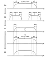
図3及び図4は、各信号のスペクトラム及び各フィルタの周波数特性を示している。
送信モデム装置100において生成される送信信号SAの送信スペクトラムの周波数特性は、次の通りである。送信信号SAのシンボルレートは「R」である。送信ルートロールオフフィルタ120のロールオフ率は「α」である。従って、図3に示されるように、送信ルートロールオフフィルタ120が適用された送信信号SAの送信スペクトラムの遷移域の幅は「αR」である。
スペクトラム分解装置200において生成されるn個の送信サブスペクトラムTSSP-1~TSSP-n(分解送信信号SB)の周波数特性は、次の通りである。ここでは、n=2の場合が例示されている。上述の図1で説明されたように、全ての送信サブスペクトラムTSSP-1~TSSP-nの帯域幅の合計(延べ帯域幅)が元の送信スペクトラムの帯域幅よりも増加しないように、スペクトラム分解(スペクトラム編集)が行われる。より詳細には、図3に示されるように、n個の送信サブスペクトラムTSSP-1~TSSP-nの各々の遷移域の幅が「αR/n」となるように、n個の送信サブスペクトラムTSSP-1~TSSP-nが生成される。各送信サブスペクトラムTSSPは、ルートロールオフ特性を有する。
図4は、スペクトラム合成装置300における受信サブスペクトラムRSSPとスペクトラム合成フィルタ310の周波数特性を示している。ここでは、n=2の場合が例示されている。n個の受信サブスペクトラムRSSP-1~RSSP-nは、それぞれ、n個の送信サブスペクトラムTSSP-1~TSSP-nに対応している。受信サブスペクトラムRSSP-1~RSSP-nの各々の遷移域の幅は「αR/n」である。それらn個の受信サブスペクトラムRSSP-1~RSSP-nのそれぞれに、n個のスペクトラム合成フィルタ310-1~310-nが適用される。各スペクトラム合成フィルタ310としては、ルートロールオフフィルタが用いられる。図4に示されるように、n個のスペクトラム合成フィルタ310-1~310-nは、それぞれ、n個の受信サブスペクトラムRSSP-1~RSSP-nと同じ周波数応答を有するように設計されている。すなわち、スペクトラム合成フィルタ310-i(i=1~n)の通過域PB及び遷移域TBは、それぞれ、受信サブスペクトラムRSSP-iの通過域及び遷移域と一致している。スペクトラム合成フィルタ310-iと受信サブスペクトラムRSSP-iの乗算の結果、遷移域は、ロールオフ率α/nのフルロールオフ特性となる。
再度図3を参照して、スペクトラム合成装置300によって合成される合成受信信号SDのスペクトラムの周波数特性を説明する。スペクトラム合成によりフルロールオフ特性の遷移域同士が重なる位置では、フラットな周波数特性が得られる。一方、合成受信信号SDのスペクトラムの左右端の遷移域は、ロールオフ率α/nのフルロールオフ特性のままである。結果として、最終的な合成受信信号SDは、シンボルレートR、ロールオフ率α/nのフルロールオフ特性のスペクトラムを有することになる。
受信モデム装置400では、受信ルートロールオフフィルタ410が合成受信信号SDに適用され、受信信号SEが生成される。このとき、シンボルレートR、ロールオフ率αの受信ルートロールオフフィルタ410が用いられる。すなわち、ロールオフ率αの受信ルートロールオフフィルタ410が、ロールオフ率α/nのフルロールオフ特性の合成受信信号SDに適用される。その結果、図3に示されるように、受信信号SEの左右端の肩の部分の電力が削られる。
山下他,"衛星中継器コグニティブ利用のためのスペクトラム分解伝送アダプタ",電子情報通信学会 信学技報, vol. 117, no. 261, SAT2017-54, pp. 115-120, 2017年10月.
上述の通り、従来技術によれば、スペクトラム分解・合成の結果、受信信号の左右端の肩の部分の電力が削られる。その結果、受信信号の復調時に符号間干渉が生じるおそれがあった。符号間干渉は、信号伝送品質の劣化を招く。
本発明の1つの目的は、スペクトラム分解・合成を利用した無線通信において、符号間干渉を抑制し、信号伝送品質を向上させることができる技術を提供することにある。
第1の観点は、送信システムと受信システムとの間で無線通信を行う無線通信システムに関連する。
送信システムは、
送信信号を出力する送信モデム装置と、
n個(nは2以上の整数)のスペクトラム分解フィルタを用いて、送信信号を周波数軸上でn個の送信サブスペクトラムに分解するスペクトラム分解装置と
を含む。
受信システムは、
n個のスペクトラム合成フィルタを用いて、n個の送信サブスペクトラムのそれぞれに対応するn個の受信サブスペクトラムを合成するスペクトラム合成装置と、
スペクトラム合成装置によって合成された合成受信信号を復調する受信モデム装置と
を含む。
n個のスペクトラム合成フィルタは、
n個の受信サブスペクトラムのうち最も低周波数側の第1受信サブスペクトラムに適用される第1スペクトラム合成フィルタと、
n個の受信サブスペクトラムのうち最も高周波数側の第n受信サブスペクトラムに適用される第nスペクトラム合成フィルタと
を含む。
第1スペクトラム合成フィルタの通過域は、第1受信サブスペクトラムと同じ周波数応答を有するスペクトラム合成フィルタの場合と比較して、低周波数方向に拡張されている。
第nスペクトラム合成フィルタの通過域は、第n受信サブスペクトラムと同じ周波数応答を有するスペクトラム合成フィルタの場合と比較して、高周波数方向に拡張されている。
送信システムは、
送信信号を出力する送信モデム装置と、
n個(nは2以上の整数)のスペクトラム分解フィルタを用いて、送信信号を周波数軸上でn個の送信サブスペクトラムに分解するスペクトラム分解装置と
を含む。
受信システムは、
n個のスペクトラム合成フィルタを用いて、n個の送信サブスペクトラムのそれぞれに対応するn個の受信サブスペクトラムを合成するスペクトラム合成装置と、
スペクトラム合成装置によって合成された合成受信信号を復調する受信モデム装置と
を含む。
n個のスペクトラム合成フィルタは、
n個の受信サブスペクトラムのうち最も低周波数側の第1受信サブスペクトラムに適用される第1スペクトラム合成フィルタと、
n個の受信サブスペクトラムのうち最も高周波数側の第n受信サブスペクトラムに適用される第nスペクトラム合成フィルタと
を含む。
第1スペクトラム合成フィルタの通過域は、第1受信サブスペクトラムと同じ周波数応答を有するスペクトラム合成フィルタの場合と比較して、低周波数方向に拡張されている。
第nスペクトラム合成フィルタの通過域は、第n受信サブスペクトラムと同じ周波数応答を有するスペクトラム合成フィルタの場合と比較して、高周波数方向に拡張されている。
第2の観点は、送信システムと受信システムとの間で無線通信を行う無線通信方法に関連する。
無線通信方法は、
送信システムの送信モデム装置から送信信号を出力するステップと、
送信システムにおいて、n個(nは2以上の整数)のスペクトラム分解フィルタを用いて、送信信号を周波数軸上でn個の送信サブスペクトラムに分解するスペクトラム分解ステップと、
受信システムにおいて、n個のスペクトラム合成フィルタを用いて、n個の送信サブスペクトラムのそれぞれに対応するn個の受信サブスペクトラムを合成するスペクトラム合成ステップと、
受信システムの受信モデム装置において、スペクトラム合成ステップによって合成された合成受信信号を復調するステップと
を含む。
n個のスペクトラム合成フィルタは、
n個の受信サブスペクトラムのうち最も低周波数側の第1受信サブスペクトラムに適用される第1スペクトラム合成フィルタと、
n個の受信サブスペクトラムのうち最も高周波数側の第n受信サブスペクトラムに適用される第nスペクトラム合成フィルタと
を含む。
第1スペクトラム合成フィルタの通過域は、第1受信サブスペクトラムと同じ周波数応答を有するスペクトラム合成フィルタの場合と比較して、低周波数方向に拡張されている。
第nスペクトラム合成フィルタの通過域は、第n受信サブスペクトラムと同じ周波数応答を有するスペクトラム合成フィルタの場合と比較して、高周波数方向に拡張されている。
無線通信方法は、
送信システムの送信モデム装置から送信信号を出力するステップと、
送信システムにおいて、n個(nは2以上の整数)のスペクトラム分解フィルタを用いて、送信信号を周波数軸上でn個の送信サブスペクトラムに分解するスペクトラム分解ステップと、
受信システムにおいて、n個のスペクトラム合成フィルタを用いて、n個の送信サブスペクトラムのそれぞれに対応するn個の受信サブスペクトラムを合成するスペクトラム合成ステップと、
受信システムの受信モデム装置において、スペクトラム合成ステップによって合成された合成受信信号を復調するステップと
を含む。
n個のスペクトラム合成フィルタは、
n個の受信サブスペクトラムのうち最も低周波数側の第1受信サブスペクトラムに適用される第1スペクトラム合成フィルタと、
n個の受信サブスペクトラムのうち最も高周波数側の第n受信サブスペクトラムに適用される第nスペクトラム合成フィルタと
を含む。
第1スペクトラム合成フィルタの通過域は、第1受信サブスペクトラムと同じ周波数応答を有するスペクトラム合成フィルタの場合と比較して、低周波数方向に拡張されている。
第nスペクトラム合成フィルタの通過域は、第n受信サブスペクトラムと同じ周波数応答を有するスペクトラム合成フィルタの場合と比較して、高周波数方向に拡張されている。
第3の観点は、送信システムと受信システムとの間で無線通信を行う無線通信システムにおけるスペクトラム合成装置に関連する。
送信システムは、
送信信号を出力する送信モデム装置と、
n個(nは2以上の整数)のスペクトラム分解フィルタを用いて、送信信号を周波数軸上でn個の送信サブスペクトラムに分解するスペクトラム分解装置と
を含む。
スペクトラム合成装置は、受信システムに含まれている。スペクトラム合成装置は、n個のスペクトラム合成フィルタを用いて、n個の送信サブスペクトラムのそれぞれに対応するn個の受信サブスペクトラムを合成するように構成されている。
n個のスペクトラム合成フィルタは、
n個の受信サブスペクトラムのうち最も低周波数側の第1受信サブスペクトラムに適用される第1スペクトラム合成フィルタと、
n個の受信サブスペクトラムのうち最も高周波数側の第n受信サブスペクトラムに適用される第nスペクトラム合成フィルタと
を含む。
第1スペクトラム合成フィルタの通過域は、第1受信サブスペクトラムと同じ周波数応答を有するスペクトラム合成フィルタの場合と比較して、低周波数方向に拡張されている。
第nスペクトラム合成フィルタの通過域は、第n受信サブスペクトラムと同じ周波数応答を有するスペクトラム合成フィルタの場合と比較して、高周波数方向に拡張されている。
送信システムは、
送信信号を出力する送信モデム装置と、
n個(nは2以上の整数)のスペクトラム分解フィルタを用いて、送信信号を周波数軸上でn個の送信サブスペクトラムに分解するスペクトラム分解装置と
を含む。
スペクトラム合成装置は、受信システムに含まれている。スペクトラム合成装置は、n個のスペクトラム合成フィルタを用いて、n個の送信サブスペクトラムのそれぞれに対応するn個の受信サブスペクトラムを合成するように構成されている。
n個のスペクトラム合成フィルタは、
n個の受信サブスペクトラムのうち最も低周波数側の第1受信サブスペクトラムに適用される第1スペクトラム合成フィルタと、
n個の受信サブスペクトラムのうち最も高周波数側の第n受信サブスペクトラムに適用される第nスペクトラム合成フィルタと
を含む。
第1スペクトラム合成フィルタの通過域は、第1受信サブスペクトラムと同じ周波数応答を有するスペクトラム合成フィルタの場合と比較して、低周波数方向に拡張されている。
第nスペクトラム合成フィルタの通過域は、第n受信サブスペクトラムと同じ周波数応答を有するスペクトラム合成フィルタの場合と比較して、高周波数方向に拡張されている。
本発明によれば、スペクトラム分解・合成を利用した無線通信において、符号間干渉を抑制し、信号伝送品質を向上させることが可能となる。
添付図面を参照して、本発明の実施の形態を説明する。
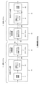
図5は、本発明の実施の形態に係る無線通信システム1の構成を概略的に示すブロック図である。無線通信システム1は、送信システム2と受信システム3を含んでいる。送信システム2と受信システム3との間で無線通信が行われる。例えば、無線通信システム1は、衛星通信システムである。その場合、衛星中継器を経由して送信システム2と受信システム3との間で無線通信が行われる。
送信システム2は、送信モデム装置10とスペクトラム分解装置20を含んでいる。受信システム3は、スペクトラム合成装置30と受信モデム装置40を含んでいる。
送信モデム装置10は、変調装置11と送信ルートロールオフフィルタ12を有している。変調装置11は、入力信号を変調して、送信信号を生成する。送信モデム装置10は、送信ルートロールオフフィルタ12を用いて送信信号の波形を成形し、送信信号SAを生成する。そして、送信モデム装置10は、送信信号SAを出力する。
スペクトラム分解装置20は、n個のスペクトラム分解フィルタ21-1~21-nを有している。ここで、nは、スペクトラム分解数であり、2以上の整数である。スペクトラム分解装置20は、送信モデム装置10から出力される送信信号SAに対して、図1で説明されたスペクトラム分解を行う。より詳細には、スペクトラム分解装置20は、送信モデム装置10から出力される送信信号SAを受け取り、高速フーリエ変換(FFT: Fast Fourier Transform)によって周波数領域における送信信号SAを取得する。更に、スペクトラム分解装置20は、n個のスペクトラム分解フィルタ21-1~21-nを用いて、送信信号SAを周波数軸上でn個の送信サブスペクトラムTSSP-1~TSSP-nに分解する。そして、スペクトラム分解装置20は、n個の送信サブスペクトラムTSSP-1~TSSP-nを所望の周波数位置(未使用帯域)にシフトさせる。つまり、スペクトラム分解装置20は、n個の送信サブスペクトラムTSSP-1~TSSP-nを所望の周波数位置に分散的に配置する。分解送信信号SBは、このようにして生成されたn個の送信サブスペクトラムTSSP-1~TSSP-nを含む。スペクトラム分解装置20は、逆高速フーリエ変換(IFFT: Inverse FFT)によって時間領域における分解送信信号SBを生成し、出力する。
送信システム2は、分解送信信号SBを受信システムに送信する。受信システム3は、分解送信信号SBを含む信号を受信信号SCとして受信する。尚、送信信号SAの元の送信スペクトラム及び分解送信信号SBの送信サブスペクトラムTSSP-1~TSSP-nの周波数位置情報が、別途、送信システム2から受信システム3に送信されてもよい。
スペクトラム合成装置30は、n個のスペクトラム合成フィルタ31-1~31-nを有している。スペクトラム合成装置30は、受信信号SCに対してスペクトラム合成を行う。より詳細には、スペクトラム合成装置30は、受信信号SCを受け取り、FFTによって周波数領域における受信信号SCを取得する。周波数領域における受信信号SCは、分解送信信号SBのn個の送信サブスペクトラムTSSP-1~TSSP-nのそれぞれに対応するn個の受信サブスペクトラムRSSP-1~RSSP-nを含んでいる。スペクトラム合成装置30は、n個のスペクトラム合成フィルタ31-1~31-nを用いることによって、n個の受信サブスペクトラムRSSP-1~RSSP-nを抽出し、合成する。このとき、スペクトラム合成装置30は、n個の受信サブスペクトラムRSSP-1~RSSP-nを元の送信信号SAの周波数位置に戻すことによって、n個の受信サブスペクトラムRSSP-1~RSSP-nを合成する。合成受信信号SD’は、このようしてスペクトラム合成装置30によって合成された受信信号である。スペクトラム合成装置30は、IFFTによって時間領域における合成受信信号SD’を生成し、出力する。
受信モデム装置40は、受信ルートロールオフフィルタ41と復調装置42を有している。受信ルートロールオフフィルタ41は、スペクトラム合成装置30から出力される合成受信信号SD’の波形を成形し、受信信号SE’を生成する。復調装置42は、受信信号SE’を復調する。
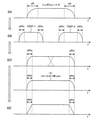
図6及び図7は、各信号のスペクトラム及び各フィルタの周波数特性を示している。
送信モデム装置10において生成される送信信号SAの送信スペクトラムの周波数特性は、次の通りである。送信信号SAのシンボルレートは「R」である。送信ルートロールオフフィルタ12のロールオフ率は「α」である。従って、図6に示されるように、送信ルートロールオフフィルタ12が適用された送信信号SAの送信スペクトラムの遷移域の幅は「αR」である。
スペクトラム分解装置20において生成されるn個の送信サブスペクトラムTSSP-1~TSSP-n(分解送信信号SB)の周波数特性は、次の通りである。ここでは、n=2の場合が例示されている。上述の図1で説明されたように、全ての送信サブスペクトラムTSSP-1~TSSP-nの帯域幅の合計(延べ帯域幅)が元の送信スペクトラムの帯域幅よりも増加しないように、スペクトラム分解(スペクトラム編集)が行われる。より詳細には、図6に示されるように、n個の送信サブスペクトラムTSSP-1~TSSP-nの各々の遷移域の幅が「αR/n」となるように、n個の送信サブスペクトラムTSSP-1~TSSP-nが生成される。各送信サブスペクトラムTSSPは、ルートロールオフ特性を有する。
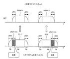
図7は、スペクトラム合成装置30における受信サブスペクトラムRSSPとスペクトラム合成フィルタ31の周波数特性を示している。ここでは、n=2の場合が例示されている。n個の受信サブスペクトラムRSSP-1~RSSP-nは、それぞれ、n個の送信サブスペクトラムTSSP-1~TSSP-nに対応している。受信サブスペクトラムRSSP-1~RSSP-nの各々の遷移域の幅は「αR/n」である。それらn個の受信サブスペクトラムRSSP-1~RSSP-nのそれぞれに、n個のスペクトラム合成フィルタ31-1~31-nが適用される。各スペクトラム合成フィルタ31としては、ルートロールオフフィルタが用いられる。
ここで、「第1スペクトラム合成フィルタ31-1」は、n個の受信サブスペクトラムRSSP-1~RSSP-nのうち最も低周波数側の第1受信サブスペクトラムRSSP-1に適用されるスペクトラム合成フィルタ31である。また、「第nスペクトラム合成フィルタ31-n」は、n個の受信サブスペクトラムRSSP-1~RSSP-nのうち最も高周波数側の第n受信サブスペクトラムRSSP-nに適用されるスペクトラム合成フィルタ31である。
図7に示されるように、本実施の形態によれば、第1スペクトラム合成フィルタ31-1の通過域PBは、図4で示されたスペクトラム合成フィルタ310-1の場合と比較して、低周波数方向に拡張される。図4で示されたスペクトラム合成フィルタ310-1は、第1受信サブスペクトラムRSSP-1と同じ周波数応答を有していた。つまり、スペクトラム合成フィルタ310-1の通過域PB及び遷移域TBは、それぞれ、第1受信サブスペクトラムRSSP-1の通過域及び遷移域と一致していた。一方、本実施の形態に係る第1スペクトラム合成フィルタ31-1の通過域PBは、第1受信サブスペクトラムRSSP-1の通過域と比較して、低周波数方向に拡張されている。
好適には、第1スペクトラム合成フィルタ31-1の通過域PBの拡張幅は、第1受信サブスペクトラムRSSP-1の低周波数側の遷移域の幅(αR/n)以上に設定される。例えば、第1スペクトラム合成フィルタ31-1の通過域PBの拡張幅は、αR(1-1/n)である。
一方、第nスペクトラム合成フィルタ31-nの通過域PBは、図4で示されたスペクトラム合成フィルタ310-nの場合と比較して、高周波数方向に拡張される。図4で示されたスペクトラム合成フィルタ310-nは、第n受信サブスペクトラムRSSP-nと同じ周波数応答を有していた。つまり、スペクトラム合成フィルタ310-nの通過域PB及び遷移域TBは、それぞれ、第n受信サブスペクトラムRSSP-nの通過域及び遷移域と一致していた。一方、本実施の形態に係る第nスペクトラム合成フィルタ31-nの通過域PBは、第n受信サブスペクトラムRSSP-nの通過域と比較して、高周波数方向に拡張されている。
好適には、第nスペクトラム合成フィルタ31-nの通過域PBの拡張幅は、第n受信サブスペクトラムRSSP-nの高周波数側の遷移域の幅(αR/n)以上に設定される。例えば、第nスペクトラム合成フィルタ31-nの通過域PBの拡張幅は、αR(1-1/n)である。
再度図6を参照して、スペクトラム合成装置30によって合成される合成受信信号SD’のスペクトラムの周波数特性を説明する。合成受信信号SD’のスペクトラムの左右端以外は、図3で示された合成受信信号SDの場合と同様である。すなわち、スペクトラム合成によりフルロールオフ特性の遷移域同士が重なる位置では、フラットな周波数特性が得られる。
一方、合成受信信号SD’のスペクトラムの左右端の遷移域は、図3で示された合成受信信号SDの場合と異なる。合成受信信号SD’のスペクトラムの左右端の遷移域は、通過域PBが拡張された第1スペクトラム合成フィルタ31-1及び第nスペクトラム合成フィルタ31-nが適用された部分である。従って、合成受信信号SD’のスペクトラムの左右端の遷移域は、ロールオフ率α/nの“ルートロールオフ特性”となる。結果として、最終的な合成受信信号SDは、シンボルレートR、ロールオフ率α/nの“ルートロールオフ特性”のスペクトラムを有することになる。
受信モデム装置40では、受信ルートロールオフフィルタ41が合成受信信号SD’に適用され、受信信号SE’が生成される。本実施の形態によれば、シンボルレートR、ロールオフ率α/nの受信ルートロールオフフィルタ41が用いられる。すなわち、ロールオフ率α/nの受信ルートロールオフフィルタ41が、ロールオフ率α/nのルートロールオフ特性の合成受信信号SD’に適用される。その結果、図6に示されるように、シンボルレートR、ロールオフ率α/nのフルロールオフ特性を有する受信信号SE’が得られる。図3で示された受信信号SEの場合とは異なり、受信スペクトラムの左右の肩の部分の電力は削られない。
受信信号SE’がフルロールオフ特性を有しているため、原理的には、受信信号SE’の復調時に符号間干渉が生じない。符号間干渉が抑制されるため、信号伝送品質が向上する。
図8は、本実施の形態の効果を説明するためのコンスタレーション図である。ここでは、変調方式としてQPSK(Quadra-Phase Shift Keying)が例示される。また、図9は、本実施の形態の効果を説明するためのグラフ図である。図9において、横軸はEb/N0(ratio of Energy per Bit to Noise Power Density)を表し、縦軸はビットエラー率(BER: Bit Error Rate)を表している。比較例は、図2~図4で示された従来技術に相当する。
比較例の場合、図8に示されるように符号間干渉が生じ、コンスタレーションが乱れる。その結果、図9に示されるように、ビットエラー率が理論特性から乖離する。このことは、信号伝送品質の劣化を意味する。
一方、本実施の形態によれば、図8に示されるように、符号間干渉が抑制され、コンスタレーションが収束する。その結果、図9に示されるように、理論特性と同等のビットエラー率が達成される。すなわち、本実施の形態によれば、信号伝送品質が向上する。
1 無線通信システム
2 送信システム
3 受信システム
10 送信モデム装置
11 変調装置
12 送信ルートロールオフフィルタ
20 スペクトラム分解装置
21-1~21-n スペクトラム分解フィルタ
30 スペクトラム合成装置
31-1~31-n スペクトラム合成フィルタ
40 受信モデム装置
41 受信ルートロールオフフィルタ
42 復調装置
2 送信システム
3 受信システム
10 送信モデム装置
11 変調装置
12 送信ルートロールオフフィルタ
20 スペクトラム分解装置
21-1~21-n スペクトラム分解フィルタ
30 スペクトラム合成装置
31-1~31-n スペクトラム合成フィルタ
40 受信モデム装置
41 受信ルートロールオフフィルタ
42 復調装置
Claims (8)
- 送信システムと受信システムとの間で無線通信を行う無線通信システムであって、
前記送信システムは、
送信信号を出力する送信モデム装置と、
n個(nは2以上の整数)のスペクトラム分解フィルタを用いて、前記送信信号を周波数軸上でn個の送信サブスペクトラムに分解するスペクトラム分解装置と
を含み、
前記受信システムは、
n個のスペクトラム合成フィルタを用いて、前記n個の送信サブスペクトラムのそれぞれに対応するn個の受信サブスペクトラムを合成するスペクトラム合成装置と、
前記スペクトラム合成装置によって合成された合成受信信号を復調する受信モデム装置と
を含み、
前記n個のスペクトラム合成フィルタは、
前記n個の受信サブスペクトラムのうち最も低周波数側の第1受信サブスペクトラムに適用される第1スペクトラム合成フィルタと、
前記n個の受信サブスペクトラムのうち最も高周波数側の第n受信サブスペクトラムに適用される第nスペクトラム合成フィルタと
を含み、
前記第1スペクトラム合成フィルタの通過域は、前記第1受信サブスペクトラムと同じ周波数応答を有するスペクトラム合成フィルタの場合と比較して、低周波数方向に拡張され、
前記第nスペクトラム合成フィルタの通過域は、前記第n受信サブスペクトラムと同じ周波数応答を有するスペクトラム合成フィルタの場合と比較して、高周波数方向に拡張されている
無線通信システム。 - 請求項1に記載の無線通信システムであって、
前記送信信号のシンボルレートはRであり、
前記送信モデム装置は、ロールオフ率がαである送信ルートロールオフフィルタを用いて前記送信信号の波形を成形し、
前記スペクトラム分解装置は、前記n個の送信サブスペクトラムの各々の遷移域の幅がαR/nとなるように、前記n個の送信サブスペクトラムを生成し、
前記第1スペクトラム合成フィルタ及び前記第nスペクトラム合成フィルタの各々の前記通過域の拡張幅は、αR/n以上である
無線通信システム。 - 請求項2に記載の無線通信システムであって、
前記通過域の前記拡張幅は、αR(1-1/n)である
無線通信システム。 - 請求項1乃至3のいずれか一項に記載の無線通信システムであって、
前記送信モデム装置は、ロールオフ率がαである送信ルートロールオフフィルタを用いて前記送信信号の波形を成形し、
前記受信モデム装置は、ロールオフ率がα/nである受信ルートロールオフフィルタを用いて前記合成受信信号の波形を成形する
無線通信システム。 - 送信システムと受信システムとの間で無線通信を行う無線通信方法であって、
前記送信システムの送信モデム装置から送信信号を出力するステップと、
前記送信システムにおいて、n個(nは2以上の整数)のスペクトラム分解フィルタを用いて、前記送信信号を周波数軸上でn個の送信サブスペクトラムに分解するスペクトラム分解ステップと、
前記受信システムにおいて、n個のスペクトラム合成フィルタを用いて、前記n個の送信サブスペクトラムのそれぞれに対応するn個の受信サブスペクトラムを合成するスペクトラム合成ステップと、
前記受信システムの受信モデム装置において、前記スペクトラム合成ステップによって合成された合成受信信号を復調するステップと
を含み、
前記n個のスペクトラム合成フィルタは、
前記n個の受信サブスペクトラムのうち最も低周波数側の第1受信サブスペクトラムに適用される第1スペクトラム合成フィルタと、
前記n個の受信サブスペクトラムのうち最も高周波数側の第n受信サブスペクトラムに適用される第nスペクトラム合成フィルタと
を含み、
前記第1スペクトラム合成フィルタの通過域は、前記第1受信サブスペクトラムと同じ周波数応答を有するスペクトラム合成フィルタの場合と比較して、低周波数方向に拡張され、
前記第nスペクトラム合成フィルタの通過域は、前記第n受信サブスペクトラムと同じ周波数応答を有するスペクトラム合成フィルタの場合と比較して、高周波数方向に拡張されている
無線通信方法。 - 請求項5に記載の無線通信方法であって、
前記送信信号のシンボルレートはRであり、
前記送信信号を出力するステップは、ロールオフ率がαである送信ルートロールオフフィルタを用いて前記送信信号の波形を成形するステップを含み、
前記スペクトラム分解ステップは、前記n個の送信サブスペクトラムの各々の遷移域の幅がαR/nとなるように、前記n個の送信サブスペクトラムを生成するステップを含み、
前記第1スペクトラム合成フィルタ及び前記第nスペクトラム合成フィルタの各々の前記通過域の拡張幅は、αR/n以上である
無線通信システム。 - 請求項5又は6に記載の無線通信方法であって、
前記送信信号を出力するステップは、ロールオフ率がαである送信ルートロールオフフィルタを用いて前記送信信号の波形を成形するステップを含み、
前記合成受信信号を復調するステップは、ロールオフ率がα/nである受信ルートロールオフフィルタを用いて前記合成受信信号の波形を成形するステップを含む
無線通信方法。 - 送信システムと受信システムとの間で無線通信を行う無線通信システムにおけるスペクトラム合成装置であって、
前記送信システムは、
送信信号を出力する送信モデム装置と、
n個(nは2以上の整数)のスペクトラム分解フィルタを用いて、前記送信信号を周波数軸上でn個の送信サブスペクトラムに分解するスペクトラム分解装置と
を含み、
前記スペクトラム合成装置は、前記受信システムに含まれており、n個のスペクトラム合成フィルタを用いて、前記n個の送信サブスペクトラムのそれぞれに対応するn個の受信サブスペクトラムを合成するように構成され、
前記n個のスペクトラム合成フィルタは、
前記n個の受信サブスペクトラムのうち最も低周波数側の第1受信サブスペクトラムに適用される第1スペクトラム合成フィルタと、
前記n個の受信サブスペクトラムのうち最も高周波数側の第n受信サブスペクトラムに適用される第nスペクトラム合成フィルタと
を含み、
前記第1スペクトラム合成フィルタの通過域は、前記第1受信サブスペクトラムと同じ周波数応答を有するスペクトラム合成フィルタの場合と比較して、低周波数方向に拡張され、
前記第nスペクトラム合成フィルタの通過域は、前記第n受信サブスペクトラムと同じ周波数応答を有するスペクトラム合成フィルタの場合と比較して、高周波数方向に拡張されている
スペクトラム合成装置。
Priority Applications (1)
| Application Number | Priority Date | Filing Date | Title |
|---|---|---|---|
| PCT/JP2020/028127 WO2022018802A1 (ja) | 2020-07-20 | 2020-07-20 | 無線通信システム、無線通信方法、及びスペクトラム合成装置 |
Applications Claiming Priority (1)
| Application Number | Priority Date | Filing Date | Title |
|---|---|---|---|
| PCT/JP2020/028127 WO2022018802A1 (ja) | 2020-07-20 | 2020-07-20 | 無線通信システム、無線通信方法、及びスペクトラム合成装置 |
Publications (1)
| Publication Number | Publication Date |
|---|---|
| WO2022018802A1 true WO2022018802A1 (ja) | 2022-01-27 |
Family
ID=79729108
Family Applications (1)
| Application Number | Title | Priority Date | Filing Date |
|---|---|---|---|
| PCT/JP2020/028127 Ceased WO2022018802A1 (ja) | 2020-07-20 | 2020-07-20 | 無線通信システム、無線通信方法、及びスペクトラム合成装置 |
Country Status (1)
| Country | Link |
|---|---|
| WO (1) | WO2022018802A1 (ja) |
Citations (3)
| Publication number | Priority date | Publication date | Assignee | Title |
|---|---|---|---|---|
| JP2011176679A (ja) * | 2010-02-25 | 2011-09-08 | Nippon Telegr & Teleph Corp <Ntt> | 無線通信システム、無線通信方法、送信装置、及び送信方法 |
| JP2015095796A (ja) * | 2013-11-13 | 2015-05-18 | 日本電信電話株式会社 | 通信装置、通信方法、帯域分割回路および帯域合成回路 |
| JP2016009928A (ja) * | 2014-06-23 | 2016-01-18 | 日本電信電話株式会社 | 通信方法、通信装置および帯域合成回路 |
-
2020
- 2020-07-20 WO PCT/JP2020/028127 patent/WO2022018802A1/ja not_active Ceased
Patent Citations (3)
| Publication number | Priority date | Publication date | Assignee | Title |
|---|---|---|---|---|
| JP2011176679A (ja) * | 2010-02-25 | 2011-09-08 | Nippon Telegr & Teleph Corp <Ntt> | 無線通信システム、無線通信方法、送信装置、及び送信方法 |
| JP2015095796A (ja) * | 2013-11-13 | 2015-05-18 | 日本電信電話株式会社 | 通信装置、通信方法、帯域分割回路および帯域合成回路 |
| JP2016009928A (ja) * | 2014-06-23 | 2016-01-18 | 日本電信電話株式会社 | 通信方法、通信装置および帯域合成回路 |
Similar Documents
| Publication | Publication Date | Title |
|---|---|---|
| US9843374B2 (en) | Transmission method, transmitter, and receiver for multi antenna wireless communication system | |
| EP1854235B1 (en) | Method and arrangement for cooperative relaying | |
| JP3563272B2 (ja) | 多重アンテナ通信システムおよびその方法 | |
| Czegledi et al. | Demonstrating 139 Gbps and 55.6 bps/Hz spectrum efficiency using 8× 8 MIMO over a 1.5-km link at 73.5 GHz | |
| US20190273536A1 (en) | Excursion compensation in multipath communication systems with a cyclic prefix | |
| JP5642863B1 (ja) | 通信装置、通信方法、帯域分割回路および帯域合成回路 | |
| WO2017109955A1 (ja) | 通信衛星、回線制御装置および衛星通信システム | |
| CN101322330A (zh) | 用于在中继节点中的子信道分配的方法 | |
| Chang et al. | Dynamic power allocation via wavefront multiplexing through multiple base stations | |
| JPH03190330A (ja) | 通信システム | |
| CN106160815A (zh) | 基于空时频码跳变的非正交多址接入方法 | |
| JP2022062166A (ja) | 通信装置及び通信方法 | |
| CN108200001B (zh) | 通信系统中信号多层调制的方法和装置 | |
| CN1612555B (zh) | 减小地面数字电视广播系统中同频转发器时延的调制设备 | |
| JP4703171B2 (ja) | 移動衛星通信システムおよび無線リソース割り当て装置 | |
| JP5208980B2 (ja) | 無線通信システム、無線通信システムにおける送信装置および送信方法 | |
| Pallavi et al. | Performance of a MIMO-OFDM-based opto-acoustic modem for high data rate underwater wireless communication (UWC) system | |
| JP4214237B2 (ja) | 送信装置、受信装置、送信方法、受信方法、ならびに、プログラム | |
| JP2006203807A (ja) | Ofdm変調装置、ofdm復調装置、ofdm変調方法及びofdm復調方法 | |
| JP7529045B2 (ja) | 無線通信システム、無線通信方法、送信装置、及び受信装置 | |
| Baidas et al. | Network-coded bi-directional relaying for amplify-and-forward cooperative networks: a comparative study | |
| JP6497825B2 (ja) | 通信装置及び通信方法 | |
| JP2007005841A (ja) | マルチキャリア伝送方法、装置、およびシステム | |
| Vinh et al. | Performance analysis of NOMA beamforming multiple users relay systems | |
| JP5897651B2 (ja) | 通信方法、通信装置および帯域合成回路 |
Legal Events
| Date | Code | Title | Description |
|---|---|---|---|
| 121 | Ep: the epo has been informed by wipo that ep was designated in this application |
Ref document number: 20945766 Country of ref document: EP Kind code of ref document: A1 |
|
| NENP | Non-entry into the national phase |
Ref country code: DE |
|
| 122 | Ep: pct application non-entry in european phase |
Ref document number: 20945766 Country of ref document: EP Kind code of ref document: A1 |
|
| NENP | Non-entry into the national phase |
Ref country code: JP |