WO2022014513A1 - 可変容量型ターボチャージャの軸受防錆装置 - Google Patents
可変容量型ターボチャージャの軸受防錆装置 Download PDFInfo
- Publication number
- WO2022014513A1 WO2022014513A1 PCT/JP2021/026067 JP2021026067W WO2022014513A1 WO 2022014513 A1 WO2022014513 A1 WO 2022014513A1 JP 2021026067 W JP2021026067 W JP 2021026067W WO 2022014513 A1 WO2022014513 A1 WO 2022014513A1
- Authority
- WO
- WIPO (PCT)
- Prior art keywords
- bearing
- variable capacity
- gas supply
- turbine
- capacity turbocharger
- Prior art date
- Legal status (The legal status is an assumption and is not a legal conclusion. Google has not performed a legal analysis and makes no representation as to the accuracy of the status listed.)
- Ceased
Links
Images


Classifications
-
- F—MECHANICAL ENGINEERING; LIGHTING; HEATING; WEAPONS; BLASTING
- F01—MACHINES OR ENGINES IN GENERAL; ENGINE PLANTS IN GENERAL; STEAM ENGINES
- F01D—NON-POSITIVE DISPLACEMENT MACHINES OR ENGINES, e.g. STEAM TURBINES
- F01D17/00—Regulating or controlling by varying flow
- F01D17/10—Final actuators
- F01D17/12—Final actuators arranged in stator parts
- F01D17/14—Final actuators arranged in stator parts varying effective cross-sectional area of nozzles or guide conduits
- F01D17/16—Final actuators arranged in stator parts varying effective cross-sectional area of nozzles or guide conduits by means of nozzle vanes
-
- F—MECHANICAL ENGINEERING; LIGHTING; HEATING; WEAPONS; BLASTING
- F02—COMBUSTION ENGINES; HOT-GAS OR COMBUSTION-PRODUCT ENGINE PLANTS
- F02B—INTERNAL-COMBUSTION PISTON ENGINES; COMBUSTION ENGINES IN GENERAL
- F02B37/00—Engines characterised by provision of pumps driven at least for part of the time by exhaust
- F02B37/12—Control of the pumps
- F02B37/24—Control of the pumps by using pumps or turbines with adjustable guide vanes
-
- Y—GENERAL TAGGING OF NEW TECHNOLOGICAL DEVELOPMENTS; GENERAL TAGGING OF CROSS-SECTIONAL TECHNOLOGIES SPANNING OVER SEVERAL SECTIONS OF THE IPC; TECHNICAL SUBJECTS COVERED BY FORMER USPC CROSS-REFERENCE ART COLLECTIONS [XRACs] AND DIGESTS
- Y02—TECHNOLOGIES OR APPLICATIONS FOR MITIGATION OR ADAPTATION AGAINST CLIMATE CHANGE
- Y02T—CLIMATE CHANGE MITIGATION TECHNOLOGIES RELATED TO TRANSPORTATION
- Y02T10/00—Road transport of goods or passengers
- Y02T10/10—Internal combustion engine [ICE] based vehicles
- Y02T10/12—Improving ICE efficiencies
Definitions
- This disclosure relates to a bearing rust preventive device for a variable capacity turbocharger.
- a plurality of movable nozzle vanes provided on a turbine nozzle are opened and closed by rotating an operation shaft protruding outside the turbine.
- the operating shaft is rotatably supported by bearings provided in the turbine housing.
- rust may infiltrate the contact area between the bearing and the operating shaft.
- friction during rotation of the operating shaft increases, which may cause rotation failure.
- the present disclosure was conceived in view of such circumstances, and an object thereof is to provide a bearing rust preventive device for a variable capacity turbocharger capable of suppressing infiltration of rust at a contact portion between a bearing and an operating shaft. ..
- Multiple nozzle vanes that can be opened and closed on the turbine nozzles,
- the link mechanism connected to the plurality of nozzle vanes and A mechanism chamber formed in the turbine housing and accommodating the link mechanism, and A bearing provided in the turbine housing and communicating the mechanism chamber with the outside of the turbine housing,
- An operating shaft rotatably provided in the bearing and having one end connected to the link mechanism,
- It is a bearing rust preventive device for variable capacity turbocharger equipped with.
- a bearing rust preventive device for a variable capacity turbocharger comprising a gas supply device configured to supply the pressure gas from the outside of the turbine toward a contact portion between the bearing and the operation shaft. Will be done.
- the operating shaft has a first contact surface formed on the mechanism chamber side and in contact with the bearing, a second contact surface formed on the outer side and in contact with the bearing, the first contact surface and the like.
- a reduced diameter portion formed between the second contact surfaces and separated from the bearing is provided.
- the gas supply device supplies pressure gas into the bearing at the axial position of the reduced diameter portion.
- the gas supply device supplies a pressure gas having a pressure higher than the pressure in the mechanism chamber.
- the pressure gas is compressed air generated by the compressor of the turbocharger.
- the pressure gas is compressed air stored in an air tank.
- the gas supply device is provided with a check valve for preventing backflow in the direction opposite to the pressure gas supply direction.
- the gas supply device includes a nozzle provided in the bearing and supplying pressure gas into the bearing, a gas supply source, and a pipe connecting the nozzle and the gas supply source.
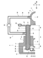
- FIG. 1 is a schematic longitudinal side view of a variable capacity turbocharger.
- FIG. 2 is an enlarged view of a main part of FIG.
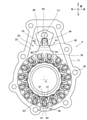
- FIG. 3 is a schematic front view when viewed from line III-III of FIG.
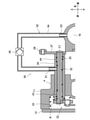
- FIG. 4 is a schematic longitudinal side view showing a state before pressure gas supply.
- FIG. 5 is a schematic longitudinal side view showing a state after pressure gas supply.
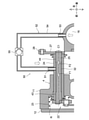
- FIG. 6 is a schematic vertical sectional side view showing a modified example.
- FIG. 1 is a schematic vertical sectional side view of the variable capacity turbocharger according to the present embodiment.
- FIG. 2 is an enlarged view of a main part of FIG. 1
- FIG. 3 is a schematic front view when the housing cover described later is removed and viewed from line III-III of FIG.
- FIG. 3 is shown as a transmission diagram.
- the internal combustion engine (also referred to as an engine) to which the turbocharger of this embodiment is applied is a diesel engine for vehicles.
- the vehicle is a large vehicle such as a truck.
- the type, type, application, etc. of the internal combustion engine are not particularly limited, and the engine may be, for example, a gasoline engine.
- the central axis of the turbine that is, the turbine axis is indicated by the symbol C.
- the axial direction, the radial direction, and the circumferential direction with respect to the turbine axis C are simply referred to as the axial direction, the radial direction, and the circumferential direction.
- the turbocharger 1 includes a turbine 2 driven by exhaust gas and a compressor 3 driven by the turbine 2 to compress or supercharge intake air.
- the turbine 2 includes a turbine housing 4 and a turbine wheel 5 rotatably provided in the turbine housing 4.
- the compressor 3 includes a compressor housing 6 and an impeller 7 rotatably provided in the compressor housing 6.
- the turbine wheel 5 and the impeller 7 are coaxially coupled to each other by the turbine shaft 8.
- the turbine housing 4 and the compressor housing 6 are coupled to a center housing 9 located between them.
- the turbine shaft 8 is rotatably supported coaxially with the turbine shaft C by the center bearing 10 in the center housing 9.
- the turbine wheel 5, the turbine shaft 8, and the impeller 7 are integrally arranged so as to be coaxial with the turbine shaft C and can rotate around the turbine shaft C.
- the turbine housing 4 has a housing body 11 that houses the turbine wheel 5, and a housing cover 12 that is fixed to the front end of the housing body 11. Inside the housing body 11, there is a nozzle 13 that supplies exhaust gas to the turbine wheel 5 from the outside in the radial direction, and a turbine scroll chamber 14 that supplies exhaust gas introduced from the turbine inlet (not shown) to the nozzle 13 at the entire circumference position. Is formed.
- a compressor scroll chamber 16 that guides the air is formed.
- the turbocharger 1 includes a plurality of nozzle vanes 21 provided to be openable and closable on the nozzle 13, a link mechanism 22 connected to the plurality of nozzle vanes 21, and a mechanism chamber 23 formed in the turbine housing 4 and accommodating the link mechanism 22.
- the turbine housing 4 includes a bearing 24 that communicates with the mechanism chamber 23 from the outside, and an operation shaft 25 that is rotatably provided in the bearing 24 and has one end (front end) connected to the link mechanism 22.
- the bearing 24 is formed as a slide bearing.
- the bearing 24 is formed of a metal pipe having a predetermined length and a constant inner and outer diameter, for example, a steel pipe, and is arranged so as to extend in the front-rear direction in parallel with the turbine shaft C.
- the bearing 24 penetrates the housing body 11 and is fixed to the housing body 11, its front end (inner end) is located inside the mechanism chamber 23, and its rear end (outer end) is outside the turbine housing 4. Be positioned.
- the operation shaft 25 is provided coaxially and rotatably in the bearing 24.
- the operating shaft 25 is rotatable around its central axis C1.
- the front and rear ends of the operating shaft 25 project from the bearing 24.
- the drive plate 26 of the link mechanism 22 is fixed to the front end of the operation shaft 25.
- An operating lever 27 is fixed to the rear end of the operating shaft 25.
- the operating lever 27 is connected to an actuator (not shown) via a link 28, and is rotationally driven around the central axis C1 by the actuator.
- the driving force of the actuator is finally transmitted to the nozzle vane 21 via the link mechanism 22.
- the actuator is formed by, for example, a servomotor.
- the operation shaft 25 has an inner contact surface 29 which is a first contact surface, an outer contact surface 30 which is a second contact surface, and a reduced diameter portion 31 formed between the inner contact surface 29 and the outer contact surface 30.
- the inner contact surface 29 is formed on the mechanism chamber 23 side in the direction of the central axis C1 and is in contact with the inner peripheral surface of the bearing 24.
- the outer contact surface 30 is formed on the outer side in the direction of the central axis C1 and is in contact with the inner peripheral surface of the bearing 24.
- the reduced diameter portion 31 is formed to have a smaller diameter than the inner contact surface 29 and the outer contact surface 30, and is separated from the inner peripheral surface of the bearing 24. As a result, a gap 32 is formed between the bearing 24 and the reduced diameter portion 31.
- the drive plate 26 rotates integrally with the operation shaft 25.
- the drive plate 26 is formed in a downward bifurcated fork shape, and a quadrangular joint plate 33 is slidably sandwiched in the fork portion.
- the rear end portion of the pin 34 is rotatably attached to the joint plate 33.
- the front end of the pin 34 is rotatably attached to the input arm 36 of the unisonring 35.
- the unisonring 35 is formed in the shape of a ring plate that goes around the turbine shaft C once, and is rotatably supported around the turbine shaft C by the housing body 11.
- the unisonring 35 is connected to a plurality of (15 in this embodiment) nozzle vanes 21 arranged at equal intervals in the circumferential direction as follows.
- the nozzle vane 21 integrally has a vane shaft 37 as its rotation axis.
- the vane shaft 37 is slidably and rotatably inserted into the bearing hole 38 of the housing body 11 and protrudes into the mechanism chamber 23.
- a vane arm 39 is fixed to the front end of the protruding vane shaft 37.
- the vane arm 39 is formed in a bifurcated fork shape facing outward in the radial direction.
- a substantially quadrangular joint plate 40 is slidably sandwiched in the fork portion.
- the rear end of the pin 41 is rotatably attached to the joint plate 40.
- the front end of the pin 41 is rotatably attached to the unisonring 35.
- reference numeral 42 indicates a plurality of female screw holes used when bolting the housing cover 12 to the housing body 11.
- Reference numeral 43 indicates an elongated hole provided in the unisonring 35 in order to avoid interference with the vane shaft 37.
- a sealed mechanism chamber 23 is formed between them.
- the link mechanism 22 is arranged in the mechanism chamber 23.
- a bearing rust preventive device is provided in order to suppress the infiltration of such rust.
- the bearing rust preventive device includes a gas supply device 50 configured to supply pressure gas from the outside of the turbine 2 toward the contact portion between the bearing 24 and the operation shaft 25.
- the gas supply device 50 includes a nozzle 51 provided in the bearing 24 and supplying pressure gas into the bearing 24, a compressor 3 as a gas supply source, and a pipe 52 connecting the nozzle 51 and the compressor 3.
- the compressor 3 is used as a gas supply source, and the compressed air generated by the compressor 3 is used as the pressure gas.
- the nozzle 51 is formed by a pipe joint (for example, a nipple) that penetrates the inside and outside of the bearing 24 and is fixed to the bearing 24.
- the nozzle 51 is arranged at a position in the direction of the central axis C1 where the reduced diameter portion 31 is located, perpendicular to the central axis C1, and is located outside the turbine housing 4.
- the nozzle 51 discharges high-pressure compressed air into the gap 32 between the bearing 24 and the reduced diameter portion 31. In this way, the gas supply device 50 supplies the pressure gas into the bearing 24 at the axial position of the reduced diameter portion 31.
- the pipe 52 includes an outlet pipe 53 attached to the compressor housing 6 and a connecting pipe 54 that connects the nozzle 51 and the outlet pipe 53.
- the outlet pipe 53 is formed by a pipe joint (for example, a nipple) that penetrates the inside and outside of the compressor housing 6 and is fixed to the compressor housing 6.
- the outlet pipe 53 is communicated with the compressor scroll chamber 16 on the downstream side of the impeller 7, and is adapted to extract compressed air from the compressor scroll chamber 16.
- the connecting pipe 54 is formed of a rubber hose or tube. However, the material of the connecting pipe 54 is arbitrary, and may be made of metal or resin.
- the upstream end of the connecting pipe 54 is connected to the outlet pipe 53, and the downstream end is connected to the nozzle 51.
- the gas supply device 50 is provided with a check valve 55 for preventing backflow in the direction opposite to the pressure gas supply direction.
- the check valve 55 is provided in the pipe 52 in the present embodiment, and is provided in the middle of the connecting pipe 54.
- the installation position is arbitrary, and may be integrated into, for example, the nozzle 51 or the outlet pipe 53.
- the check valve 55 allows only the flow from the compressor 3 side to the bearing 24 side, and prohibits the flow in the reverse direction.
- the contact portion is a contact portion (referred to as an inner contact portion) 43 of the inner contact surface 29 and the bearing 24, and a contact portion (referred to as an outer contact portion) 44 of the outer contact surface 30 and the bearing 24.
- the exhaust temperature is low, so the water vapor contained in the exhaust may condense below the dew point and condensate water may be generated. ..
- Sulfuric acid, nitric acid, organic acids and the like produced in the combustion process of fuel are dissolved in the condensed water, so that the condensed water is highly corrosive acidic water. Therefore, when the condensed water adheres to the inside of the mechanism chamber 23, rust is likely to occur.
- the rust generated in the mechanism chamber 23 partially peels off and moves in the chamber, passes through the gap between the drive plate 26 and the front end surface of the bearing 24, and invades the inner contact portion 43. After that, it moves outward in the central axis C1 direction, sequentially passes through the gap 32 and the outer contact portion 44, and is finally discharged to the outside.
- other foreign substances may infiltrate and move in the rust.
- Rust may be discharged from the contact portions 43 and 44 due to the rotation of the operation shaft 25, but when the deposition rate exceeds the discharge rate, the deposition amount gradually increases.
- compressed air is supplied into the bearing 24 by the gas supply device 50 in order to suppress the adhesion of rust to the contact portions 43 and 44.
- the operation at this time will be described with reference to FIGS. 4 and 5.
- FIG. 4 shows a state in which rust R is attached before the compressed air is supplied. Rust R adheres not only to the inner contact portion 43 and the outer contact portion 44 but also to various places.
- the compressed air is divided into a flow F1 toward the inside of the turbine housing 4 and a flow F2 toward the outside.
- the inward flow F1 pushes out the rust R adhering to the inner contact portion 43 and discharges it into the mechanism chamber 23.
- the outward flow F2 pushes out the rust R adhering to the outer contact portion 44 and discharges it to the outside. In this way, the rust adhering to the inner contact portion 43 and the outer contact portion 44 can be removed. At the same time, the rust adhering to the gap 32 can also be removed.
- the gas supply device 50 supplies a pressure gas having a pressure higher than the pressure in the mechanism chamber 23.
- the gas supply device 50 since the gas supply device 50 is provided, it is possible to suppress the infiltration of rust R in the contact portions 43 and 44 of the bearing 24 and the operation shaft 25.
- the rust R infiltrated into the inner contact portion 43 can be reliably discharged into the mechanism chamber 23.
- the compressed air generated by the compressor 3 of the turbocharger 1 is used as the pressure gas, it is not necessary to separately provide a gas supply source, and the configuration can be simplified. Further, the distance from the gas supply source to the gas supply position (nozzle 51) can be shortened, and the pressure loss can be reduced.
- the pressure gas from the outside of the turbine 2 since the pressure gas from the outside of the turbine 2 is supplied, it is advantageous for suppressing rust adhesion at the contact portion. That is, when the pressure gas from the inside of the turbine 2, that is, the exhaust gas is supplied to the contact portion, as described above, the contact portion is further rusted by the acidic water caused by the condensation of the exhaust gas. However, in the present embodiment, since the pressure gas from the outside of the turbine 2 is supplied, such rusting can be avoided and the rust prevention effect can be enhanced.
- an air tank 61 provided separately from the turbocharger 1 may be used as a pressure gas supply source, and compressed air stored in the air tank 61 may be used as the pressure gas.
- compressed air stored in the air tank 61 may be used as the pressure gas.
- a gas other than air for example, a nonflammable gas such as nitrogen or argon may be used.
- the contact portion between the bearing and the operation shaft may be one. In this case, it is preferable to directly supply the pressure gas to the contact portion.
- a solenoid valve may be provided instead of the check valve, and this solenoid valve may be controlled by a control unit.
- the bearing rust preventive device includes a gas supply device including an electromagnetic valve, a control unit, a first pressure sensor for detecting the pressure in the mechanism chamber, and a second pressure sensor for detecting the gas pressure of the gas supply source. Be prepared.
- the control unit opens the solenoid valve when the gas pressure detected by the second pressure sensor is higher than the mechanism chamber pressure detected by the first pressure sensor, and closes the solenoid valve in other cases.
- an electronic control unit ECU (Electronic Control Unit) mounted on the vehicle for engine control can be used.
Landscapes
- Engineering & Computer Science (AREA)
- Mechanical Engineering (AREA)
- General Engineering & Computer Science (AREA)
- Chemical & Material Sciences (AREA)
- Combustion & Propulsion (AREA)
- Supercharger (AREA)
- Control Of Turbines (AREA)
Abstract
可変容量型ターボチャージャ1は、タービン2のノズル13に開閉可能に設けられた複数のノズルベーン21と、複数のノズルベーンに連結されたリンク機構22と、タービンハウジング4内に形成されリンク機構を収容する機構室23と、タービンハウジングに設けられ機構室とタービンハウジングの外部を連通する軸受24と、軸受内に回転可能に設けられ一端がリンク機構に接続された操作軸25とを備える。可変容量型ターボチャージャの軸受防錆装置は、軸受と操作軸の接触部43,44に向かって、タービンの外から圧力ガスを供給するように構成されたガス供給装置50を備える。
Description
本開示は可変容量型ターボチャージャの軸受防錆装置に関する。
一般的に可変容量型ターボチャージャでは、タービンのノズルに設けられた複数の可動ノズルベーンを、タービンの外に突出された操作軸を回転させて開閉する。操作軸は、タービンハウジングに設けられた軸受によって回転可能に支持される。
しかし、軸受と操作軸の接触部に錆が浸入することがある。こうした錆の浸入が起こると、操作軸の回転時におけるフリクションが増加し、回転不良が生じる可能性がある。
そこで本開示は、かかる事情に鑑みて創案され、その目的は、軸受と操作軸の接触部における錆の浸入を抑制することができる可変容量型ターボチャージャの軸受防錆装置を提供することにある。
本開示の一の態様によれば、
タービンのノズルに開閉可能に設けられた複数のノズルベーンと、
前記複数のノズルベーンに連結されたリンク機構と、
タービンハウジング内に形成され前記リンク機構を収容する機構室と、
前記タービンハウジングに設けられ前記機構室と前記タービンハウジングの外部を連通する軸受と、
前記軸受内に回転可能に設けられ前記リンク機構に接続された一端を有する操作軸と、
を備えた可変容量型ターボチャージャの軸受防錆装置であって、
前記軸受と前記操作軸の接触部に向かって前記タービンの外から前記圧力ガスを供給するように構成されたガス供給装置を備える
ことを特徴とする可変容量型ターボチャージャの軸受防錆装置が提供される。
タービンのノズルに開閉可能に設けられた複数のノズルベーンと、
前記複数のノズルベーンに連結されたリンク機構と、
タービンハウジング内に形成され前記リンク機構を収容する機構室と、
前記タービンハウジングに設けられ前記機構室と前記タービンハウジングの外部を連通する軸受と、
前記軸受内に回転可能に設けられ前記リンク機構に接続された一端を有する操作軸と、
を備えた可変容量型ターボチャージャの軸受防錆装置であって、
前記軸受と前記操作軸の接触部に向かって前記タービンの外から前記圧力ガスを供給するように構成されたガス供給装置を備える
ことを特徴とする可変容量型ターボチャージャの軸受防錆装置が提供される。
好ましくは、前記操作軸は、前記機構室側に形成され前記軸受に接触される第1接触面と、外部側に形成され前記軸受に接触される第2接触面と、前記第1接触面および前記第2接触面の間に形成され前記軸受から離間される縮径部とを備え、
前記ガス供給装置は、前記縮径部の軸方向位置において前記軸受内に圧力ガスを供給する。
前記ガス供給装置は、前記縮径部の軸方向位置において前記軸受内に圧力ガスを供給する。
好ましくは、前記ガス供給装置は、前記機構室内の圧力より高圧の圧力ガスを供給する。
好ましくは、前記圧力ガスは、前記ターボチャージャのコンプレッサにより生成された圧縮空気である。
好ましくは、前記圧力ガスは、エアタンクに貯留された圧縮空気である。
好ましくは、前記ガス供給装置は、圧力ガス供給方向と反対方向の逆流を防止するための逆止弁を備える。
好ましくは、前記ガス供給装置は、前記軸受に設けられ前記軸受内に圧力ガスを供給するノズルと、ガス供給源と、前記ノズルおよび前記ガス供給源を接続する配管とを備える。
本開示によれば、軸受と操作軸の接触部における錆の浸入を抑制することができる。
以下、添付図面を参照して本開示の実施形態を説明する。なお本開示は以下の実施形態に限定されない点に留意されたい。
図1は、本実施形態に係る可変容量型ターボチャージャの概略縦断側面図である。図2は図1の要部拡大図であり、図3は後述のハウジングカバーを取り外して図1のIII-III線から見たときの概略正面図である。理解容易のため、図3は透過図で示してある。
本実施形態のターボチャージャが適用される内燃機関(エンジンともいう)は、車両用ディーゼルエンジンである。車両はトラック等の大型車両である。但し内燃機関の種類、形式、用途等に特に限定はなく、例えばエンジンはガソリンエンジンであってもよい。
便宜上、前後左右上下の各方向を図示の通り定める。但しこれら各方向が説明の便宜上定められたものに過ぎない点に留意されたい。
タービンの中心軸すなわちタービン軸を符号Cで示す。以下特に断らない限り、タービン軸Cを基準とした軸方向、半径方向および周方向を単に軸方向、半径方向および周方向というものとする。
ターボチャージャ1は、排気によって駆動されるタービン2と、タービン2によって駆動され吸入空気を圧縮もしくは過給するコンプレッサ3とを備える。タービン2は、タービンハウジング4と、タービンハウジング4内に回転可能に設けられたタービンホイール5とを備える。コンプレッサ3は、コンプレッサハウジング6と、コンプレッサハウジング6内に回転可能に設けられたインペラ7とを備える。タービンホイール5とインペラ7はタービンシャフト8により互いに同軸に結合される。タービンハウジング4とコンプレッサハウジング6は、それらの間に位置されたセンターハウジング9に結合される。センターハウジング9内のセンターベアリング10によってタービンシャフト8がタービン軸Cと同軸に回転可能に支持される。これによりタービンホイール5、タービンシャフト8およびインペラ7が一体となって、タービン軸Cと同軸に配置され、かつ、タービン軸Cの回りを回転可能である。
タービンハウジング4は、タービンホイール5を収容するハウジング本体11と、ハウジング本体11の前端部に固定されたハウジングカバー12とを有する。ハウジング本体11の内部には、排気をタービンホイール5に半径方向外側から供給するノズル13と、タービン入口(図示せず)から導入した排気をノズル13に全周位置で供給するタービンスクロール室14とが形成される。
コンプレッサハウジング6の内部には、インペラ7から排出された圧縮空気を半径方向外側に向かって案内するディフューザ15と、ディフューザ15から排出された圧縮空気をコンプレッサ出口(図示せず)に向かって周方向に案内するコンプレッサスクロール室16とが形成される。
またターボチャージャ1は、ノズル13に開閉可能に設けられた複数のノズルベーン21と、複数のノズルベーン21に連結されたリンク機構22と、タービンハウジング4内に形成されリンク機構22を収容する機構室23と、タービンハウジング4に設けられ機構室23と外部を連通する軸受24と、軸受24内に回転可能に設けられ一端(前端)がリンク機構22に接続された操作軸25とを備える。
軸受24は、すべり軸受として形成される。軸受24は、所定長さを有し内外径が一定の金属管、例えば鋼管により形成され、タービン軸Cと平行に前後方向に延びて配置される。軸受24は、ハウジング本体11を貫通してハウジング本体11に固定され、その前端部(内側端部)は機構室23内に位置され、その後端部(外側端部)はタービンハウジング4の外部に位置される。
この軸受24内に操作軸25が同軸かつ回転可能に設けられる。操作軸25は、その中心軸C1の回りを回転可能である。操作軸25の前端と後端は軸受24から突出されている。操作軸25の前端には、リンク機構22の駆動板26が固定されている。操作軸25の後端には、操作レバー27が固定されている。操作レバー27は、リンク28を介してアクチュエータ(図示せず)に連結され、アクチュエータによって中心軸C1回りに回転駆動される。アクチュエータの駆動力はリンク機構22を介して最終的にノズルベーン21に伝達される。アクチュエータは例えばサーボモータにより形成される。
操作軸25は、第1接触面である内側接触面29と、第2接触面である外側接触面30と、内側接触面29および外側接触面30の間に形成された縮径部31とを備える。内側接触面29は、中心軸C1の方向における機構室23側に形成され、軸受24の内周面に接触される。外側接触面30は、中心軸C1の方向における外部側に形成され、軸受24の内周面に接触される。縮径部31は、内側接触面29および外側接触面30より小径に形成され、軸受24の内周面から離間される。これにより軸受24と縮径部31の間には隙間32が形成される。
リンク機構22において、駆動板26は操作軸25と一体に回転するようになっている。駆動板26は下向きの二股フォーク状に形成され、そのフォーク部分には四角形のジョイント板33がスライド可能に挟まれる。ジョイント板33にはピン34の後端部が回転可能に取り付けられる。ピン34の前端部はユニゾンリング35の入力アーム部36に回転可能に取り付けられる。ユニゾンリング35は、タービン軸Cの回りを1周するリング板状に形成され、ハウジング本体11により、タービン軸Cの回りに回転可能に支持される。
ユニゾンリング35は、周方向等間隔で配置された複数(本実施形態では15個)のノズルベーン21に以下の如く連結される。まずノズルベーン21は、その回転軸となるベーンシャフト37を一体的に有する。ベーンシャフト37はハウジング本体11の軸受穴38に摺動回転可能に挿通され、機構室23内に突出される。その突出されたベーンシャフト37の前端部にはベーンアーム39が固定されている。
ベーンアーム39は、半径方向外側に向く二股フォーク状に形成される。そのフォーク部分には略四角形のジョイント板40がスライド可能に挟まれる。ジョイント板40にはピン41の後端部が回転可能に取り付けられる。ピン41の前端部はユニゾンリング35に回転可能に取り付けられる。
これにより、操作軸25の回転がリンク機構22を通じてノズルベーン21に伝達され、ノズルベーン21が回転される。図3に示すように、操作軸25がA1方向に回転されるとユニゾンリング35がB1方向に回転され、ノズルベーン21がV1方向すなわち閉弁方向に回転される。逆に、操作軸25がA2方向に回転されるとユニゾンリング35がB2方向に回転され、ノズルベーン21がV2方向すなわち開弁方向に回転される。
図3において符号42は、ハウジング本体11にハウジングカバー12をボルト止めする際に用いる複数の雌ネジ穴を示す。符号43は、ベーンシャフト37の干渉を避けるためにユニゾンリング35に設けられた長孔を示す。
ハウジング本体11にハウジングカバー12を取り付けると、これらの間に密閉された機構室23が形成される。リンク機構22はこの機構室23内に配置される。
こうしたターボチャージャ1においては、軸受24と操作軸25の接触部に錆が浸入し、操作軸25の回転時におけるフリクションが増加し、回転不良が生じる可能性がある。
そこで本実施形態では、こうした錆の浸入を抑制するため軸受防錆装置を設けている。軸受防錆装置は、軸受24と操作軸25の接触部に向かってタービン2外からの圧力ガスを供給するように構成されたガス供給装置50を備える。
ガス供給装置50は、軸受24に設けられ軸受24内に圧力ガスを供給するノズル51と、ガス供給源としてのコンプレッサ3と、ノズル51およびコンプレッサ3を接続する配管52とを備える。本実施形態では、コンプレッサ3をガス供給源として用い、コンプレッサ3により生成された圧縮空気を圧力ガスとして用いる。
ノズル51は、軸受24の内外を貫通して軸受24に固定された管継手(例えばニップル)により形成される。ノズル51は、縮径部31のある中心軸C1方向の位置に、中心軸C1に垂直に配置されると共に、タービンハウジング4の外部に位置される。ノズル51は、軸受24と縮径部31の間の隙間32に、高圧の圧縮空気を排出する。このようにガス供給装置50は、縮径部31の軸方向位置において軸受24内に圧力ガスを供給する。
配管52は、コンプレッサハウジング6に取り付けられた出口管53と、ノズル51および出口管53を連結する連結管54とを備える。出口管53は、ノズル51と同様、コンプレッサハウジング6の内外を貫通してコンプレッサハウジング6に固定された管継手(例えばニップル)により形成される。出口管53は、インペラ7の下流側のコンプレッサスクロール室16に連通され、コンプレッサスクロール室16から圧縮空気を抽出するようになっている。
連結管54は、ゴム製のホースまたはチューブにより形成される。但し連結管54の材質は任意であり、金属製または樹脂製であってもよい。連結管54の上流端は出口管53に、下流端はノズル51に接続される。
またガス供給装置50は、圧力ガス供給方向と反対方向の逆流を防止するための逆止弁55を備える。逆止弁55は、本実施形態では配管52に設けられ、連結管54の途中に設けられる。但しその設置位置は任意であり、例えばノズル51または出口管53に一体的に組み込んでもよい。逆止弁55は、コンプレッサ3側から軸受24側への流れのみを許容し、逆方向の流れを禁止する。
さて、前述したように、軸受24と操作軸25の接触部に錆が浸入し、所謂もらい錆の状態となることがある。この接触部とは、内側接触面29および軸受24の接触部(内側接触部という)43と、外側接触面30および軸受24の接触部(外側接触部という)44とである。
錆の原因は様々であるが、主に、タービンハウジング4の機構室23内で発生した錆が挙げられる。ノズル13を通過する排気は、ベーンシャフト37と軸受穴38の間の僅かな隙間を通じて、微量ではあるが、機構室23内に漏れ出す。この排気に起因して機構室23内に錆が発生する。
特に、エンジンの低負荷運転時および低温運転時、ならびに外気温が低温の環境下では、排気温度が低いため、排気に含まれる水蒸気が露点を下回って凝縮し、凝縮水が発生することがある。凝縮水には、燃料の燃焼過程で生成される硫酸、硝酸、有機酸等が溶け込んでいるため、凝縮水は腐食性の高い酸性水である。そのため、凝縮水が機構室23内に付着すると錆が発生し易くなる。
エンジン運転中は、機構室23内に排気が漏れ出すため、機構室23内の圧力は、外部の大気圧より高くなる。従って機構室23から、軸受24と操作軸25の間を通って、外部に漏れ出る排気の流れが生成される。この流れに乗って機構室23内の錆も移動する。
機構室23内で発生した錆は、一部剥離して室内を移動し、駆動板26と軸受24前端面との隙間を通過して、内側接触部43に浸入する。その後、中心軸C1方向外側に移動して隙間32と外側接触部44を順次通過し、最終的に外部に排出される。なお錆に混じって他の異物が浸入、移動することもある。
一方、他の原因として、ターボチャージャ1の外表面部、特に外側接触部44付近で発生した錆が挙げられる。冬期には、路面に凍結防止剤として塩(岩塩や、塩化カルシウム等の融雪剤)が散布されることがある。この塩が、ターボチャージャ1の外表面部に付着した雨水や凝縮水に混入し、腐食性の高い塩水を生じさせる。この塩水によりターボチャージャ1の外表面部が錆びる。
錆の一部は剥離して外側接触部44に接近する。そしてこの錆は、操作レバー27と軸受24後端面との間の隙間を通過した後、外側接触部44に浸入する。その後、さらに中心軸C1方向内側に移動して隙間32と内側接触部43に順次浸入することもある。
上述の錆の移動過程において、錆が内側接触部43と外側接触部44に止まり、堆積する。操作軸25の回転により接触部43,44から錆が排出されることがあるが、堆積速度が排出速度を上回ると、堆積量が徐々に増加する。
接触部43,44に錆が付着、堆積すると、操作軸25の回転時におけるフリクションが増加し、最悪、操作軸25が軸受24に固着して動かなくなる。すると、操作軸25に回転不良が生じ、操作軸25の回転動作、ひいてはノズルベーン21の開閉動作が正常に行われなくなる可能性がある。
そこで本実施形態では、接触部43,44への錆の付着を抑制するため、ガス供給装置50によって軸受24内に圧縮空気を供給する。この際の作動を図4および図5を参照して説明する。
図4は、圧縮空気供給前の錆Rが付着した状態を示す。錆Rは、内側接触部43および外側接触部44のみならず随所に付着している。
この状態で、コンプレッサスクロール室16内の圧力が機構室23内の圧力より高くなると、逆止弁55が開弁し、図5に矢印で示すように、コンプレッサスクロール室16内の圧縮空気が出口管53および連結管54を順に通じて、ノズル51から隙間32内に供給される。
圧縮空気は、タービンハウジング4の内側に向かう流れF1と、外側に向かう流れF2とに分かれる。内側に向かう流れF1は、内側接触部43に付着していた錆Rを押し出し、機構室23内に排出する。外側に向かう流れF2は、外側接触部44に付着していた錆Rを押し出し、外部に排出する。こうして、内側接触部43および外側接触部44に付着していた錆を除去することができる。このとき同時に、隙間32に付着していた錆も除去することができる。
また、コンプレッサスクロール室16内の圧力が機構室23内の圧力より高いとき、圧縮空気が常時供給されるので、上記流れF1,F2により内側接触部43および外側接触部44への新たな錆Rの浸入を抑制することができる。よって錆Rの付着を予防することができる。
このようにガス供給装置50は、機構室23内の圧力より高圧の圧力ガスを供給する。
一方、コンプレッサスクロール室16内の圧力が機構室23内の圧力以下のときには、逆止弁55が閉弁される。よって、機構室23内の排気がコンプレッサスクロール室16内に逆流するのを抑制することができる。
このように本実施形態によれば、ガス供給装置50を設けたので、軸受24と操作軸25の接触部43,44における錆Rの浸入を抑制することができる。
また本実施形態によれば、内側接触部43および外側接触部44という二つの接触部を設けた場合でも、両接触部への錆Rの浸入を効果的に抑制することができる。
また本実施形態によれば、機構室23内の圧力より高圧の圧縮空気を供給するので、内側接触部43に浸入した錆Rを確実に機構室23内に排出できる。
また本実施形態によれば、ターボチャージャ1のコンプレッサ3により生成された圧縮空気を圧力ガスとして利用するので、ガス供給源を別途設けずに済み、構成の簡素化を図れる。またガス供給源からガス供給位置(ノズル51)までの距離を短縮し、圧力損失を低減できる。
また本実施形態によれば、タービン2外からの圧力ガスを供給するので、接触部での錆付着抑制に有利である。すなわち、タービン2内からの圧力ガス、つまり排気を接触部に供給してしまうと、上述したように、排気の凝縮に起因する酸性水により接触部が益々錆びてしまう。しかしながら本実施形態では、タービン2外からの圧力ガスを供給するので、こうした錆付きを回避することができ、防錆効果を高めることができる。
以上、本開示の実施形態を詳細に述べたが、本開示の実施形態および変形例は他にも様々考えられる。
(1)例えば、図6に示すように、ターボチャージャ1とは別に設けられたエアタンク61を圧力ガスの供給源とし、エアタンク61に貯留された圧縮空気を圧力ガスとして使用してもよい。本実施形態の車両の場合、ブレーキ等の作動のためにこうしたエアタンク61を備えているので、これを利用することで、別途ガス供給源を設けずに済む。
(2)圧力ガスとして、空気以外の気体、例えば窒素、アルゴン等の不燃性ガスを用いてもよい。
(3)軸受と操作軸の接触部は一つであってもよい。この場合、接触部に圧力ガスを直接供給するのが好ましい。
(4)逆止弁の代わりに電磁弁を設け、この電磁弁を制御ユニットによって制御してもよい。この場合、軸受防錆装置は、電磁弁を含むガス供給装置と、制御ユニットと、機構室内の圧力を検出する第1圧力センサと、ガス供給源のガス圧力を検出する第2圧力センサとを備える。制御ユニットは、第2圧力センサにより検出されたガス圧力が、第1圧力センサにより検出された機構室内圧力より高い場合に電磁弁を開弁し、それ以外の場合に電磁弁を閉弁する。制御ユニットには、例えば、エンジン制御のために車両に搭載された電子制御ユニット(ECU(Electronic Control Unit))を用いることができる。
本開示の実施形態は前述の実施形態のみに限らず、特許請求の範囲によって規定される本開示の思想に包含されるあらゆる変形例や応用例、均等物が本開示に含まれる。従って本開示は、限定的に解釈されるべきではなく、本開示の思想の範囲内に帰属する他の任意の技術にも適用することが可能である。
本出願は、2020年7月15日付で出願された日本国特許出願(特願2020-121558)に基づくものであり、その内容はここに参照として取り込まれる。
1 ターボチャージャ
2 タービン
3 コンプレッサ
4 タービンハウジング
13 ノズル
21 ノズルベーン
22 リンク機構
23 機構室
24 軸受
25 操作軸
29 内側接触面
30 外側接触面
31 縮径部
43 内側接触部
44 外側接触部
50 ガス供給装置
51 ノズル
52 配管
55 逆止弁
61 エアタンク
2 タービン
3 コンプレッサ
4 タービンハウジング
13 ノズル
21 ノズルベーン
22 リンク機構
23 機構室
24 軸受
25 操作軸
29 内側接触面
30 外側接触面
31 縮径部
43 内側接触部
44 外側接触部
50 ガス供給装置
51 ノズル
52 配管
55 逆止弁
61 エアタンク
Claims (7)
- タービンのノズルに開閉可能に設けられた複数のノズルベーンと、
前記複数のノズルベーンに連結されたリンク機構と、
タービンハウジング内に形成され前記リンク機構を収容する機構室と、
前記タービンハウジングに設けられ前記機構室と前記タービンハウジングの外部を連通する軸受と、
前記軸受内に回転可能に設けられ前記リンク機構に接続された一端を有する操作軸と、
を備えた可変容量型ターボチャージャの軸受防錆装置であって、
前記軸受と前記操作軸の接触部に向かって、前記タービンの外から圧力ガスを供給するように構成されたガス供給装置を備える
ことを特徴とする可変容量型ターボチャージャの軸受防錆装置。 - 前記操作軸は、前記機構室側に形成され前記軸受に接触される第1接触面と、外部側に形成され前記軸受に接触される第2接触面と、前記第1接触面および前記第2接触面の間に形成され前記軸受から離間される縮径部とを備え、
前記ガス供給装置は、前記縮径部の軸方向位置において前記軸受内に前記圧力ガスを供給する
請求項1に記載の可変容量型ターボチャージャの軸受防錆装置。 - 前記ガス供給装置は、前記機構室内の圧力より高圧の前記圧力ガスを供給する
請求項1または2に記載の可変容量型ターボチャージャの軸受防錆装置。 - 前記圧力ガスは、前記ターボチャージャのコンプレッサにより生成された圧縮空気である
請求項1~3のいずれか一項に記載の可変容量型ターボチャージャの軸受防錆装置。 - 前記圧力ガスは、エアタンクに貯留された圧縮空気である
請求項1~3のいずれか一項に記載の可変容量型ターボチャージャの軸受防錆装置。 - 前記ガス供給装置は、圧力ガス供給方向と反対方向の逆流を防止するための逆止弁を備える
請求項1~5のいずれか一項に記載の可変容量型ターボチャージャの軸受防錆装置。 - 前記ガス供給装置は、前記軸受に設けられ前記軸受内に圧力ガスを供給するノズルと、ガス供給源と、前記ノズルおよび前記ガス供給源を接続する配管とを備える
請求項1~6のいずれか一項に記載の可変容量型ターボチャージャの軸受防錆装置。
Priority Applications (1)
| Application Number | Priority Date | Filing Date | Title |
|---|---|---|---|
| CN202180061142.7A CN116134213B (zh) | 2020-07-15 | 2021-07-12 | 可变容量型涡轮增压器的轴承防锈装置 |
Applications Claiming Priority (2)
| Application Number | Priority Date | Filing Date | Title |
|---|---|---|---|
| JP2020121558A JP7251528B2 (ja) | 2020-07-15 | 2020-07-15 | 可変容量型ターボチャージャの軸受防錆装置 |
| JP2020-121558 | 2020-07-15 |
Publications (1)
| Publication Number | Publication Date |
|---|---|
| WO2022014513A1 true WO2022014513A1 (ja) | 2022-01-20 |
Family
ID=79555483
Family Applications (1)
| Application Number | Title | Priority Date | Filing Date |
|---|---|---|---|
| PCT/JP2021/026067 Ceased WO2022014513A1 (ja) | 2020-07-15 | 2021-07-12 | 可変容量型ターボチャージャの軸受防錆装置 |
Country Status (3)
| Country | Link |
|---|---|
| JP (1) | JP7251528B2 (ja) |
| CN (1) | CN116134213B (ja) |
| WO (1) | WO2022014513A1 (ja) |
Families Citing this family (1)
| Publication number | Priority date | Publication date | Assignee | Title |
|---|---|---|---|---|
| JP7649402B1 (ja) * | 2024-04-19 | 2025-03-19 | 株式会社Cygames | プログラム、ゲーム進行方法、及びゲームサーバ |
Citations (7)
| Publication number | Priority date | Publication date | Assignee | Title |
|---|---|---|---|---|
| JPS5376213A (en) * | 1976-12-17 | 1978-07-06 | Saab Scania Ab | Turbo charger |
| JPS6119602U (ja) * | 1984-07-10 | 1986-02-04 | トヨタ自動車株式会社 | タ−ボチヤ−ジヤのノズルベ−ン冷却装置 |
| JPS62108503U (ja) * | 1985-12-25 | 1987-07-10 | ||
| JP2009068375A (ja) * | 2007-09-11 | 2009-04-02 | Toyota Motor Corp | 内燃機関の可変ノズル式過給機 |
| JP2009114928A (ja) * | 2007-11-06 | 2009-05-28 | Honda Motor Co Ltd | 過給装置付き内燃機関 |
| JP2015127518A (ja) * | 2013-12-27 | 2015-07-09 | 株式会社Ihi | 軸受構造および過給機 |
| JP2017527739A (ja) * | 2014-09-23 | 2017-09-21 | ボーグワーナー インコーポレーテッド | 一体型アクチュエータを備えるターボチャージャ |
Family Cites Families (11)
| Publication number | Priority date | Publication date | Assignee | Title |
|---|---|---|---|---|
| JP2004263836A (ja) * | 2003-03-04 | 2004-09-24 | Nsk Ltd | 電動コンプレッサ用転がり軸受 |
| EP1816317B1 (en) * | 2006-02-02 | 2013-06-12 | IHI Corporation | Turbocharger with variable nozzle |
| JP4935628B2 (ja) * | 2007-10-30 | 2012-05-23 | 株式会社Ihi | 過給機 |
| JP4946983B2 (ja) * | 2008-06-23 | 2012-06-06 | 株式会社Ihi | ターボチャージャ |
| JP2010071142A (ja) * | 2008-09-17 | 2010-04-02 | Ihi Corp | ターボチャージャ |
| JP5641823B2 (ja) * | 2010-08-26 | 2014-12-17 | ダイハツ工業株式会社 | 可変ノズル型過給構造 |
| JP2013253521A (ja) * | 2012-06-06 | 2013-12-19 | Ihi Corp | 可変ノズルユニット及び可変容量型過給機 |
| US9664060B2 (en) * | 2013-03-01 | 2017-05-30 | Ihi Corporation | Variable nozzle unit and variable geometry system turbocharger |
| JP6403027B2 (ja) * | 2015-02-26 | 2018-10-10 | 日立ジョンソンコントロールズ空調株式会社 | スクリュー圧縮機 |
| WO2017149747A1 (ja) * | 2016-03-04 | 2017-09-08 | 三菱重工業株式会社 | ターボチャージャー |
| CN110529197B (zh) * | 2019-10-10 | 2024-09-17 | 兰州长城机械工程有限公司 | 一种适用于高温烟气轮机的可调静叶装置 |
-
2020
- 2020-07-15 JP JP2020121558A patent/JP7251528B2/ja active Active
-
2021
- 2021-07-12 WO PCT/JP2021/026067 patent/WO2022014513A1/ja not_active Ceased
- 2021-07-12 CN CN202180061142.7A patent/CN116134213B/zh active Active
Patent Citations (7)
| Publication number | Priority date | Publication date | Assignee | Title |
|---|---|---|---|---|
| JPS5376213A (en) * | 1976-12-17 | 1978-07-06 | Saab Scania Ab | Turbo charger |
| JPS6119602U (ja) * | 1984-07-10 | 1986-02-04 | トヨタ自動車株式会社 | タ−ボチヤ−ジヤのノズルベ−ン冷却装置 |
| JPS62108503U (ja) * | 1985-12-25 | 1987-07-10 | ||
| JP2009068375A (ja) * | 2007-09-11 | 2009-04-02 | Toyota Motor Corp | 内燃機関の可変ノズル式過給機 |
| JP2009114928A (ja) * | 2007-11-06 | 2009-05-28 | Honda Motor Co Ltd | 過給装置付き内燃機関 |
| JP2015127518A (ja) * | 2013-12-27 | 2015-07-09 | 株式会社Ihi | 軸受構造および過給機 |
| JP2017527739A (ja) * | 2014-09-23 | 2017-09-21 | ボーグワーナー インコーポレーテッド | 一体型アクチュエータを備えるターボチャージャ |
Also Published As
| Publication number | Publication date |
|---|---|
| JP7251528B2 (ja) | 2023-04-04 |
| JP2022018448A (ja) | 2022-01-27 |
| CN116134213B (zh) | 2026-02-27 |
| CN116134213A (zh) | 2023-05-16 |
Similar Documents
| Publication | Publication Date | Title |
|---|---|---|
| KR101698013B1 (ko) | 유량 가변 밸브 기구 및 과급기 | |
| CN102072011B (zh) | 多级涡轮增压器系统和方法 | |
| EP1972785B1 (en) | Check valve for a vacuum pump | |
| US8844282B2 (en) | Exhaust-gas turbocharger having a ball-cock waste-gate valve with a stress-relieved crank arm | |
| US20160011070A1 (en) | Method for Checking the Leak Tightness of a Combustion Engine Having an Exhaust Gas Turbocharger, and Exhaust Gas Turbocharger | |
| US20090064678A1 (en) | Multiple-turbocharger system, and exhaust gas flow control valve therefor | |
| CN114829754A (zh) | 包括涡轮增压器的排气添加剂配给系统 | |
| US10371148B2 (en) | Vacuum pump | |
| JP7251528B2 (ja) | 可変容量型ターボチャージャの軸受防錆装置 | |
| US9739311B2 (en) | Bearing structure and turbocharger | |
| CN110195670B (zh) | 特别是用于供应高压气体设有通气口的节流阀体或致动器 | |
| KR102478082B1 (ko) | 차량용 터보차저 | |
| US20180003134A1 (en) | Egr device | |
| WO2015044742A1 (en) | Seal structure of turbocharger | |
| CN103649490A (zh) | 多级增压系统 | |
| US20210123360A1 (en) | Bearing structure | |
| KR102744492B1 (ko) | 회전식 액시얼 밸브 | |
| KR100307938B1 (ko) | 진공펌프장치 | |
| CN209430313U (zh) | 废气再循环阀单元 | |
| WO2004088108A1 (en) | Automotive turbocharger systems | |
| US11598251B2 (en) | Turbine wastegate having a fluidic sealing arrangement and a method of testing thereof | |
| CN108397294A (zh) | 具有流体截止阀的机器系统和方法 | |
| JP2012172519A (ja) | フラップバルブ | |
| JP2013015103A (ja) | ウェイストゲートバルブ及び過給機 | |
| JP6590734B2 (ja) | ロータリー弁装置、過給機、および、多段過給システム |
Legal Events
| Date | Code | Title | Description |
|---|---|---|---|
| 121 | Ep: the epo has been informed by wipo that ep was designated in this application |
Ref document number: 21843145 Country of ref document: EP Kind code of ref document: A1 |
|
| NENP | Non-entry into the national phase |
Ref country code: DE |
|
| 122 | Ep: pct application non-entry in european phase |
Ref document number: 21843145 Country of ref document: EP Kind code of ref document: A1 |