WO2022014490A1 - 異物付着防止装置 - Google Patents
異物付着防止装置 Download PDFInfo
- Publication number
- WO2022014490A1 WO2022014490A1 PCT/JP2021/025946 JP2021025946W WO2022014490A1 WO 2022014490 A1 WO2022014490 A1 WO 2022014490A1 JP 2021025946 W JP2021025946 W JP 2021025946W WO 2022014490 A1 WO2022014490 A1 WO 2022014490A1
- Authority
- WO
- WIPO (PCT)
- Prior art keywords
- irradiation
- light
- window surface
- foreign matter
- prevention device
- Prior art date
- Legal status (The legal status is an assumption and is not a legal conclusion. Google has not performed a legal analysis and makes no representation as to the accuracy of the status listed.)
- Ceased
Links
Images





Classifications
-
- B—PERFORMING OPERATIONS; TRANSPORTING
- B08—CLEANING
- B08B—CLEANING IN GENERAL; PREVENTION OF FOULING IN GENERAL
- B08B17/00—Methods preventing fouling
-
- B—PERFORMING OPERATIONS; TRANSPORTING
- B08—CLEANING
- B08B—CLEANING IN GENERAL; PREVENTION OF FOULING IN GENERAL
- B08B17/00—Methods preventing fouling
- B08B17/02—Preventing deposition of fouling or of dust
Definitions
- the present invention relates to a foreign matter adhesion prevention device.
- Underwater structures installed underwater such as seawater system equipment in power generation facilities such as thermal power plants and nuclear power plants, are provided with glass or acrylic inspection windows for equipment inspection. It is known that sessile organisms such as barnacles and mussels and foreign substances such as biofilms are likely to adhere to such underwater structures and their inspection windows. When foreign matter adheres to the inspection window, it is difficult to see the outside from the inspection window, and it is difficult to inspect the underwater structure. Therefore, the inspection window may be provided with a scraper for removing the foreign matter by rotating the wiper.
- Patent Document 1 is a technique for preventing the adhesion and growth of living organisms by irradiating an optical window that transmits light with ultraviolet rays.
- ultraviolet rays are harmful to the human eye, it is not preferable to leak them to the outside where they can be seen by the human eye.
- iron compounds also form a film on the surface of inspection windows, which was clarified by the studies by the inventors.
- the current situation is that the method for preventing the formation of the above-mentioned film has not been disclosed.
- the present invention has been made in view of the above, and an object of the present invention is to provide a foreign matter adhesion prevention device that ensures safety and prevents foreign matter from adhering to the window surface of an underwater structure.
- the present invention has a light emitting portion that irradiates the window surface of the underwater structure with the irradiation light, and a shielding portion that can prevent the irradiation light from leaking into the underwater structure.
- the irradiation light has a peak in the wavelength range of 405 to 412 nm, and the irradiation light has an irradiation intensity of 25 Wm when the divalent iron ion concentration in the water outside the window surface is less than 0.1 mg / L.
- the irradiation light when divalent iron ions concentration in water of the window surface outside is 0.1 mg / L or more, the range irradiation intensity of 25Wm -2 ⁇ 100Wm -2 It relates to a foreign matter adhesion prevention device, which is the light inside.
- the shielding portion is between a closed state in which the irradiation light is prevented from leaking into the underwater structure and an open state in which the window surface is visible from the inside of the underwater structure.
- the foreign matter adhesion prevention device according to any one of (1) to (3), which is provided so as to be openable and closable with respect to the window surface and is irradiated with the irradiation light only in the closed state.
- the light emitting unit has a control unit and a sensor unit, the sensor unit can detect the open state and the closed state, and the sensor unit detects the open state.
- the control unit controls to stop the irradiation of the irradiation light, and when the sensor unit detects the closed state, the control unit controls to irradiate the irradiation light.
- the shielding portion has a lock mechanism capable of holding the closed state, and the lock mechanism holds the closed state when the irradiation light is irradiated, and the closed state when the irradiation light is not irradiated.
- the light emitting unit has an LED light emitting panel including a plurality of LED light emitting elements, and irradiates at least half the area of the window surface with the irradiation light according to any one of (1) to (6).
- the described foreign matter adhesion prevention device has an LED light emitting panel including a plurality of LED light emitting elements, and irradiates at least half the area of the window surface with the irradiation light according to any one of (1) to (6).
- the shielding portion has a conical shape that extends with respect to the window surface, and the light emitting portion is arranged at the apex of the shielding portion having the conical shape, and the irradiation light is applied to the window surface.
- the foreign matter adhesion prevention device according to any one of (1) to (6), which has a point light source for irradiating.
- the present invention can provide a foreign matter adhesion prevention device that ensures safety and prevents foreign matter from adhering to the window surface of an underwater structure.
- the foreign matter adhesion prevention device 1 prevents foreign matter from adhering to the inspection window surface 110, which is the inspection window portion of the underwater structure 100.
- the underwater structure 100 is not particularly limited, and examples thereof include seawater system equipment (filter, sponge ball cleaning device, shell removal device) in a power generation facility such as a thermal power plant and a nuclear power plant. These facilities are equipped with inspection windows for checking the operating status such as backwashing of the filter.
- the underwater structure 100 is not limited to the above, and is not limited to the above, but is not limited to the above, and is not limited to the above, but is not limited to the above.
- Iron ions may be injected into the seawater, freshwater, or brackish water around the underwater structure 100 for the purpose of anticorrosion of the underwater structure 100.
- an injection device that injects an iron ion source such as ferrous sulfate into seawater, fresh water, or brackish water around the condenser in order to prevent corrosion of the condenser capillary tube.
- the injection device injects divalent iron ions so that, for example, the divalent iron ion concentration is 0.3 ppm x 6 hours / day or the divalent iron ion concentration is 1.0 ppm x 2 hours / day during the initial operation. ..
- the injection device injects divalent iron ions so that the divalent iron ion concentration is, for example, 0.1 ppm ⁇ 6 hours / day or the divalent iron ion concentration is 0.5 ppm ⁇ 1 hour / day during normal operation. ..
- the concentration of divalent iron ions outside the inspection window surface 110 is 0.1 mg / L or more, the inspection window surface 110 contains not only sessile organisms or biofilms but also iron caused by the iron ions.
- the compound can form an iron film and impair visibility for equipment inspection.
- the material constituting the inspection window surface 110 is not particularly limited as long as it is a light-transmitting member, and for example, glass such as quartz glass and soda glass, light-transmitting resin such as acrylic and polyvinyl chloride, and the like are used. Can be mentioned.
- the inspection window surface 110 is provided with a scraper 111 for removing foreign matter adhering to the inspection window, for example.
- the scraper 111 is configured to rotate a wiper provided on the outside (underwater side surface) of the inspection window by rotating the handle to remove foreign matter adhering to the outer surface of the inspection window.
- the foreign matter adhesion prevention device 1 has a light emitting unit 20 and a shielding unit 30.
- the light emitting unit 20 has a peak in the wavelength range of 405 to 412 nm, and irradiates the inspection window surface 110 with irradiation light having an irradiation intensity of 25 Wm-2 or more.
- irradiation light when the external bivalent iron ion concentration in water of the sight glass surface 110 is 0.1 mg / L or more, the irradiation intensity is adjusted in the range of 25Wm -2 ⁇ 100Wm -2.
- the shielding unit 30 can cover the light irradiation unit 21 and prevents the irradiation light harmful to the human eye from leaking into the underwater structure 100.
- the water passage point of the underwater structure 100 is inside a part of the underwater structure 100 shown in the cylindrical shape in FIG.
- the inspector of the underwater structure 100 can inspect the operating status of the underwater structure 100 by visually recognizing the water passage portion through, for example, the inspection window surface 110.
- the "outside of the underwater structure” is the outside of the underwater structure, and is a concept including the above-mentioned water passage point.
- the "inside of the underwater structure” means the inside of the underwater structure 100 and the area on the inspector side with respect to the inspection window surface 110. That is, the above water passage point is not included in the concept of "inside the underwater structure".
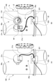
- FIG. 1A shows a closed state of the shielding portion 30 (hereinafter, may be simply referred to as a “closed state”) in which the leakage of the irradiation light into the underwater structure 100 is prevented
- FIG. B shows an open state of the shielding portion 30 (hereinafter, may be simply referred to as “open state”) in which the inspection window surface 110 becomes visible from the inside of the underwater structure 100.
- the shielding portion 30 is kept in a closed state except when the underwater structure 100 is inspected.
- the above-mentioned attached organisms are floating in the sea during the early larvae, and when they become adherent larvae, they are organisms that attach to appropriate deposits and metamorphose into adults, and examples thereof include mussels and barnacles.
- Mussels are a general term for bivalves of the Musaceae family, such as the subfamily Modolilinae such as mussels, the subfamily Lithophagainae such as Lithophaga curta, and the subfamily Lithophagainae such as mussels and mussels. Crenellinae), mussels, mussels, mussels and other subfamilies of mussels (Mytilinae) and the like are included.
- the barnacles are a general term for those classified into crustacea, cerlipadia, and barnacles, such as barnacles, barnacles, barnacles, barnacles, and barnacles. Includes those belonging to the barnacle-type suborder (Balanomophorpha), including barnacles, barnacles, barnacles, barnacles, barnacles, barnacles, barnacles, and barnacles.
- the biofilm is a structure formed by microorganisms on the surface of a window surface such as an inspection window surface of an underwater structure.
- Biofilms are usually membranous and contain extracellular high molecular weight substances (EPS, exopolylular polymeric substance) such as polysaccharides secreted by microorganisms.
- EPS extracellular high molecular weight substances
- the biofilm may also contain microbial remains, excrement, feces, burrows and the like.
- the microorganism can be exemplified by an organism belonging to bacteria, fungi, blue-green algae, protozoa and the like.
- microalgae such as adherent diatoms, green algae, brown algae and red algae, and larvae such as kaimen, hydroins, jellyfish, tube-dwelling polychaetes, gammaridea and gammaridea.
- the iron-containing compound is a compound produced by oxidizing iron ions in water, and the iron-containing compound forms a film on the surface of the inspection window surface 110.
- Iron ions in water may be injected into water for the purpose of anticorrosion of the underwater structure 100.
- the iron-containing compound include iron (II) oxide (FeO), iron (III) oxide (Fe 2 O 3 ), iron oxyhydroxide (FeOOH), iron hydroxide (Fe (OH) 2 ), and the like.
- examples thereof include ferric hydroxide (Fe (OH) 3).
- the iron-containing compound is negatively charged in seawater and the inspection window surface 110 is positively charged, an electrostatic attraction acts on the inspection window surface 110, and the iron-containing compound is applied to the inspection window surface 110. Is deposited to form a film. However, it is considered that the irradiation of the irradiation light suppresses the positive charge of the inspection window surface 110, and as a result, the deposition of the iron-containing compound on the inspection window surface 110 is suppressed.
- the irradiation light emitted from the light emitting unit 20 has a peak in the wavelength range of 405 to 412 nm.
- Ultraviolet rays having a wavelength of 380 nm or less have an effect of suppressing attached organisms, but have a problem of low transmittance in seawater.
- the irradiation light preferably has a peak in the wavelength range of 400 to 420 nm.
- the wavelength of the irradiation light may include a wavelength range other than the above as long as the effect of the present invention is not impaired. For example, it may contain light in the wavelength range of 400 to 440 nm.
- the irradiation intensity of the irradiation light is 25 Wm-2 or more when the divalent iron ion concentration in the water outside the inspection window surface 110 is less than 0.1 mg / L.
- the irradiation intensity of the irradiation light is in the range of 25 to 100 Wm-2 when the divalent iron ion concentration in the water outside the inspection window surface 110 is 0.1 mg / L or more.
- the irradiation intensity is preferably in the range of 25 to 50 Wm-2 when the concentration of divalent iron ions in the water outside the inspection window surface 110 is 0.1 mg / L or more.
- the irradiation intensity is a value obtained as a measured value of Pyranometer LI-200 manufactured by Meiwaforsis Co., Ltd.
- the adhesion of foreign matter to the inspection window surface 110 is preferably suppressed.
- concentration of divalent iron ions in the water outside the inspection window surface 110 is 0.1 mg / L or more and the irradiation intensity of the irradiation light exceeds 100 Wm-2 , the adhesion of the film formed by the iron-containing compound is suppressed.
- the irradiation intensity of the irradiation light is less than 25 Wm-2 , it may not be possible to obtain a sufficient effect of suppressing the adhesion of attached organisms.
- the irradiation time of the light is not particularly limited and may be continuous or intermittent. When it is intermittent, it is preferable that the average irradiation intensity at a predetermined time is within the above range.
- the light emitting unit 20 may be, for example, an LED irradiation device that irradiates LED light, a mercury lamp, a fluorescent tube, or the like. Among them, it is preferable that the LED irradiation device is used, and it is preferable to have an optical fiber that irradiates the LED or an LED light emitting panel composed of a plurality of LED light emitting elements.
- the light emitting unit 20 according to the present embodiment has an optical fiber.
- the light emitting unit 20 has a light irradiation unit 21 and a main body unit 22.
- the main body 22 has a control unit (not shown) that controls the light emitted from the light irradiation unit 21.
- the main body portion 22 is housed inside the housing portion 221 and is fixed by the fixing portion 222.
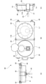
- FIG. 5A shows a front view of the main body portion 22 and the housing portion 221
- FIG. 5B also shows a left side view
- FIG. 5C also shows a right side view.
- the light emitting unit 20 may have a sensor unit 40.
- the light irradiation unit 21 is an exit port of the optical fiber 23, and the irradiation light emitted from the light irradiation unit 21 is applied to the irradiation region L1 which is at least a part of the inspection window surface 110.
- the irradiation region L1 is a partial circular region of the inspection window surface 110.
- the irradiation light Lc emitted from the light irradiation unit 21 reaches the inspection window surface 110 with a slight spread from the exit port, but is within the surface of the inspection window surface 110. Only irradiated. With the irradiation region L1, there is no risk of deterioration due to irradiation of the shielding portion 30 covering the light irradiation portion 21, and the room for selecting the material constituting the shielding portion 30 can be widened.
- the main body 22 is an irradiation device of an LED point light source capable of irradiating LED light as irradiation light.
- the main body 22 is not particularly limited, and conventionally known ones can be used.
- the main body 22 has a projection lens 220 that irradiates LED light as a point light source. The irradiation light emitted from the light projecting lens 220 is transmitted to the light irradiation unit 21 through the optical fiber 23.
- the main body unit 22 has a control unit (not shown) and can control the irradiation of the LED light emitted from the floodlight lens 220.
- the control unit is configured to be communicable with, for example, the sensor unit 40 described later, and when the sensor unit 40 detects an open state, the control unit controls to stop the irradiation of the LED light, and the sensor unit 40 controls the closed state. When is detected, control is performed to irradiate the LED light. As a result, it is possible to reliably prevent the LED light emitted from the light emitting unit 20 from leaking into the underwater structure 100, and it is possible to improve the safety of the foreign matter adhesion prevention device 1.
- the sensor unit 40 is configured to be able to communicate with the control unit of the main body unit 22 by wire or wirelessly, and is arranged inside, for example, the door unit 31 of the shielding unit 30 described later.
- the sensor unit 40 is not particularly limited as long as it is a sensor capable of detecting the open state and the closed state of the shielding unit 30, and is, for example, a magnetic sensor, a pressure sensitive sensor, an ultrasonic sensor, a capacitance sensor, a distance measuring sensor, or the like.
- a known sensor capable of detecting contact or proximity with the sensor can be used.
- the housing portion 221 accommodates the main body portion 22.
- the housing portion 221 is fixed by the fixing portion 222.
- the housing portion 221 has a lid portion that can be opened and closed, and the lid portion is fixed by the fixing portion 222.
- the fixing portion 222 is a known magnet holder having a magnet such as a neodymium magnet, and can firmly fix an object with a force that cannot be moved by human power, for example, about 800N.
- the magnetic force of the fixed portion 222 can be switched by the operating portion 223.
- the operation unit 223 may be configured to stop the irradiation of the LED light of the main body unit 22 when the fixing of the lid portion of the housing portion 221 is released. As a result, it is possible to prevent the main body 22 from being operated by accidentally opening the lid of the housing 221 while the LED light is being emitted from the light projecting lens 220 of the main body 22. Therefore, the foreign matter adhesion prevention device 1 The safety of the lens can be further improved.
- the shielding portion 30 has a door portion 31, a frame portion 32, and an opening / closing mechanism 33.
- the shielding portion 30 has a grip portion 34, a locking mechanism 35, and a window portion 36, as shown in FIG. 6 (A) is a top view of the shield 30 in the closed state, FIG. 6 (B) is a front view of the shield 30 in the open state, and FIG. 6 (C) is a right side view of the shield 30 in the closed state. Are shown respectively.
- the door portion 31 is connected to the frame portion 32 via the opening / closing mechanism 33, and is provided so as to be openable / closable with respect to the inspection window surface 110.
- the state in which the door portion 31 is in contact with the frame portion 32 is the closed state, and the state in which the door portion 31 is rotated by the opening / closing mechanism 33 and separated from the frame portion 32 is the open state.
- the opening / closing mechanism 33 a known opening / closing mechanism such as a hinge is used.
- the door portion 31 is a member having a recess on the surface facing the frame portion 32.
- a light irradiation unit 21 is connected to the front surface of the door unit 31.
- the LED light emitted from the light irradiation unit 21 is emitted from the front side of the door unit 31 toward the inspection window surface 110.
- the LED light is emitted in the area surrounded by the recess of the door portion 31 and the frame portion 32 in the closed state and reaches the inspection window surface 110, so that the LED light does not leak into the underwater structure 100.
- the frame portion 32 has a shape corresponding to the door portion 31, is arranged so as to surround the circumference of the inspection window surface 110, and is fixed to the underwater structure 100.
- the frame portion 32 and the door portion 31 are in contact with each other and fixed in the closed state.
- a member such as packing may be arranged between the door portion 31 and the frame portion 32 in the closed state. This makes it possible to prevent the LED light from leaking from between the door portion 31 and the frame portion 32.
- the material of the door portion 31 and the frame portion 32 is not particularly limited, and materials such as resin and metal can be used.
- the grip portion 34 is a handle for opening and closing the door portion 31.
- the lock mechanism 35 is a mechanism capable of fixing the closed door portion 31 and the frame portion 32 and holding the closed state.
- the lock mechanism 35 is not particularly limited, and a known lockable lock mechanism such as a snap lock is used.
- the lock mechanism 35 keeps the closed state when the LED light is irradiated, and releases the closed state when the LED light is not irradiated.
- the lock mechanism 35 is interlocked with the energizing device or power supply device that supplies power for operation to the main body 22 and the lock mechanism 35 is released from the closed state, the energization to the main body 22 is cut off. Can be configured to be.
- the LED light is not irradiated in the open state, it is possible to reliably prevent the LED light from leaking into the underwater structure 100.
- the window portion 36 is provided on the front surface of the door portion 31 and is a window portion that allows the inside of the shielding portion 30 to be confirmed when the shielding portion 30 is closed.
- the window portion 36 is normally fixed by a fixing tool or the like so that it cannot be opened or closed.
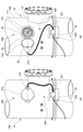
- FIG. 2 is a diagram showing a foreign matter adhesion prevention device 1a according to the second embodiment of the present invention.
- FIG. 2A shows a closed state of the shielding portion 30a
- FIG. 2B shows an open state of the shielding portion 30a.
- the foreign matter adhesion prevention device 1a has a light emitting unit 20a and a shielding unit 30a.
- the light emitting unit 20a has an LED light emitting panel including a plurality of LED light emitting elements.
- the light emitting unit 20a can adjust the irradiation intensity of the LED light as a whole of the light emitting unit 20a without depending on a single light emitting element. Further, by keeping the output of each LED element low, it can be expected that the life of the device will be extended.
- the light emitting unit 20a can also make a part of the light irradiation unit 21a emit light.
- the light irradiation unit 21a is an LED light emitting panel.
- the light irradiation unit 21a includes, for example, a plurality of LED elements arranged in a panel frame, a light guide plate, and a reflection sheet.
- the LED light emitted from the plurality of LED elements toward the center of the panel is uniformly emitted from the entire surface of the panel by the light guide plate and the reflective sheet.
- the main body 22 has a control unit that supplies electric power to the light irradiation unit 21a and controls the output.
- the light irradiation unit 21a and the main body unit 22 are connected by a power line and a communication line.
- the irradiation region L2 of the irradiation light irradiated from the light irradiation unit 21a to the inspection window surface 110 is at least half the area of the inspection window surface 110 as shown in FIG. 2 (B).
- a wider area on the inspection window surface 110 where foreign matter is prevented from adhering can be secured as compared with the first embodiment. Therefore, the inspection of the underwater structure 100 can be performed more preferably.
- FIG. 3 is a diagram showing a foreign matter adhesion prevention device 1b according to a third embodiment of the present invention.
- FIG. 3A shows a closed state of the shielding portion 30b
- FIG. 2B shows an open state of the shielding portion 30b.
- the foreign matter adhesion prevention device 1b has a light emitting unit 20b and a shielding unit 30b.
- the light emitting unit 20b has an optical fiber that irradiates the LED light of the point light source, as in the first embodiment.
- the shielding portion 30b has a door portion 31b having a conical shape that extends with respect to the inspection window surface 110.
- the light irradiation unit 21b of the light emitting unit 20b which is a point light source, is arranged at the apex of the door portion 31b having a conical shape.
- the irradiation region L3 of the irradiation light irradiated from the light irradiation unit 21b to the inspection window surface 110 is a region including the entire surface of the inspection window surface 110 as shown in FIG. 3 (B).
- FIG. 4 is a diagram showing a foreign matter adhesion prevention device 1c according to the fourth embodiment of the present invention.
- FIG. 4A shows a closed state of the shielding portion 30c
- FIG. 4B shows an open state of the shielding portion 30c.
- the foreign matter adhesion prevention device 1c has a light emitting unit 20c and a shielding unit 30c. Like the light emitting unit 20a, the light emitting unit 20c includes an LED light emitting panel including a plurality of LED light emitting elements. Therefore, the foreign matter adhesion prevention device 1c has the same configuration as the foreign matter adhesion prevention device 1a according to the second embodiment, and the same effect can be obtained.
- the light irradiation unit 21c is an LED light emitting panel.
- the LED light emitting panel can be freely shaped, and the light irradiation unit 21c has a shape corresponding to the inspection window surface 110. Therefore, as shown in FIG. 4B, the irradiation region L4 of the irradiation light emitted from the light irradiation unit 21c to the inspection window surface 110 is a region including the entire surface of the inspection window surface 110. As a result, it is possible to prevent foreign matter from adhering to the entire surface of the inspection window surface 110, and it is possible to more preferably inspect the underwater structure 100.
- the present invention is not limited to the above embodiment, and can be appropriately modified.
- the window surface of the underwater structure 100 has been described as the inspection window surface 110, but the present invention is not limited to the above.
- the window surface may have a purpose other than inspection.
- the LED light source As the LED light source, a high power LED light source manufactured by U-Technology Co., Ltd. was used. The irradiation intensity of the LED light of the affixa plate was adjusted so that the irradiation intensity of each affixa plate at a distance of 10 cm from the optical fiber ejection port was 1000 Wm- 2.
- FIG. 7 is a photograph showing the adhesion state one month after the start of the test
- FIG. 8 is a photograph showing the adhesion state two months after the start of the test.
- FIGS. 7 and 8 in order from the left, photographs of the affixa plate without light irradiation and with LED light having a peak wavelength of 405 nm are shown.
- the scale on the right side indicates the distance (cm) from the optical fiber outlet.
- the attachment plate irradiated with the LED light having a peak wavelength of 405 nm is in the irradiation range of the LED light radially emitted from the optical fiber ejection port arranged on the upper part of the attachment plate. The result was that no attached organisms or biofilms were attached.
- the attachment plate not irradiated with the LED light had attached organisms, biofilms, and the like adhered to the entire surface.
- the irradiation regions L are regions of about 40 mm ⁇ 40 mm, respectively, as shown in FIG. 9A, and the irradiation intensities on the inspection window surface 110 are set to the above-mentioned irradiation intensities.
- the LED light source the LED module SRDB-40UV40-405 (manufactured by U-Technology Co., Ltd.) was used so that the distance between the light irradiation unit 21 and the inspection window surface 110 was 100 mm.
- other inspection windows of the same shell removal device were replaced with new ones at the same time to make a control section.
- FIG. 10 is a photograph of the test group taken 11 weeks after the start of the test
- FIG. 11 is a photograph of the control group taken 11 weeks after the start of the test.
- Arrows W in FIGS. 10 and 11 indicate the direction of the water flow.
- the white spots in the inspection windows of FIGS. 10 and 11 are spots to which barnacles B have adhered. As shown in FIGS. 10 and 11, many barnacles B adhered to the upstream side of the water flow W where seawater tends to stay.
- Figure 10 shows the test group, in the left half of the sight glass, 25Wm -2, and the irradiation vicinity area L of the light 50Wm -2, attachment of barnacles B and biofilm was suppressed.
- the formation of a thick yellow iron hydroxide film was confirmed in the irradiation region L of 200 Wm-2.
- the formation of iron hydroxide film was also confirmed at 25 Wm -2 and 50 Wm -2 , but it was very thin and the formation of iron film was suppressed.
- the biofilm was attached to the inspection window surface 110 other than the irradiation region L.
- barnacles B were concentratedly adhered to the left half surface of the inspection window.
- the entire surface was covered with thick detritus (which is thought to be biofilmed by the bacteria existing inside it).
- the irradiation intensity of the LED light of 405 nm to the range of 25 Wm -2 to 100 Wm -2 , the adhesion of attached organisms and biofilm can be suppressed, and the adhesion of the film formed by the compound containing iron can be suppressed. Results that can be suppressed were confirmed.
- irradiation region L is a circular region having a diameter of 50 mm (diameter 60 mm on the light emitting surface from the inspection window) shown in FIGS. 12 (A) and 12 (B), and the irradiation intensity on the inspection window surface 110 is the above. The irradiation intensity was adjusted.
- a 405 nm wavelength LED light source UFSL-501-08UV-UT (manufactured by U-Technology Co., Ltd.) was used, and the distance between the light irradiation unit 21 and the inspection window surface 110 was set to 100 mm.
- the inspection windows in the test area were cleaned before the start of the test, and the inspection windows cleaned at the same time were used as the control area.
- FIG. 13 is a photograph taken in the vicinity of the irradiation area L of the test group where the irradiation intensity was 50 Wm- 2 8 weeks after the start of the test.
- FIG. 14 is a photograph of the vicinity of the irradiation region L of the test group in which the irradiation intensity was set to 200 Wm- 2 8 weeks after the start of the test.
- FIG. 15 is a photograph of the vicinity of the irradiation region L of the test group in which the irradiation intensity was set to 200 Wm- 2 38 weeks after the start of the test.
- FIG. 16 is a photograph of a control group taken 38 weeks after the start of the test. In FIG.
- FIG. 13 which shows the test group of 50 Wm- 2 , the formation of an iron hydroxide film was confirmed in the irradiation region L, but it was very thin and the formation of the iron film was suppressed. In addition, no adhesion of biofilm or the like occurred.
- FIG. 14 which shows the test group of 200 Wm- 2 , the formation of the iron hydroxide film I was confirmed in the irradiation region L.
- FIG. 15 shows a test group of 200 Wm -2, formation of similar thick yellow iron hydroxide coating and irradiation area L of 200 Wm -2 in Figure 10 was confirmed. No attachment of attached organisms or biofilms occurred in the irradiation region L of FIGS. 13 to 16.
- barnacles B may have adhered to locations other than the irradiation region L.
- FIG. 16 showing the target group barnacles or periphyton were observed on the entire surface. Therefore, it was confirmed that when the irradiation intensity of the LED light of 405 nm is 50 Wm- 2 , the adhesion of attached organisms and biofilm can be suppressed, and the adhesion of the film formed by the compound containing iron can be suppressed.
- the irradiation intensity may be 200 Wm -2, results coating of thick iron hydroxide as compared to the case where the 50Wm -2 is formed was confirmed.
Landscapes
- Prevention Of Fouling (AREA)
- Physical Water Treatments (AREA)
- Catching Or Destruction (AREA)
Abstract
安全性を確保し、かつ水中構造物の窓面に対する異物の付着を防止する異物付着防止装置を提供する。 照射光を水中構造物100の点検窓面110に対して照射する発光部20と、照射光の水中構造物100内部への漏洩を防止可能な遮蔽部30と、を有し、上記前記照射光は、405~412nmの波長域においてピークを有し、上記照射光は、前記窓面外部の水中の2価鉄イオン濃度が0.1mg/L未満である場合には、照射強度が25Wm-2以上の光であり、上記照射光は、前記窓面外部の水中の2価鉄イオン濃度が0.1mg/L以上である場合には、照射強度が25Wm-2~100Wm-2の範囲内の光である、異物付着防止装置1。上記照射光の照射により、点検窓面110に対する付着生物又はバイオフィルム、若しくは鉄を含む化合物により形成される皮膜の付着が抑制される。
Description
本発明は、異物付着防止装置に関する。
水中に設置される水中構造物、例えば、火力発電所、原子力発電所等の発電施設における海水系統の設備には、設備点検のためのガラス又はアクリル製の点検窓が設けられている。このような水中構造物及びその点検窓に対しては、フジツボ類やイガイ類等の付着生物やバイオフィルム等の異物が付着しやすいことが知られている。点検窓に異物が付着した状態では、点検窓から外部を視認し難く、水中構造物の点検を行うことが困難である。このため、点検窓には、ワイパーを回動させることで上記異物を除去するスクレーパが設けられている場合がある。
しかし、上記スクレーパでは、点検窓に強固に付着した異物を完全に除去できない場合がある。このため、水中機器の窓面に対して紫外線を照射することで、窓面に対する生物の付着を防止する技術が開示されている(特許文献1参照)。
特許文献1に開示された技術は、光を透過させる光学窓に対して紫外線を照射することで、生物の付着及び成長を防止する技術である。しかし、紫外線は人の目に対して有害であるため、人の目に触れる外部に漏洩することは好ましくない。また、付着生物やバイオフィルム以外に、鉄化合物により点検窓表面に皮膜が形成されることも今回、発明者らの検討により明らかとなった。しかし、上記皮膜の形成を防止する方法は開示されていないのが現状だった。
本発明は、上記に鑑みてなされたものであり、安全性を確保し、かつ水中構造物の窓面に対する異物の付着を防止する異物付着防止装置を提供することを目的とする。
(1) 本発明は、照射光を水中構造物の窓面に対して照射する発光部と、前記照射光の前記水中構造物内部への漏洩を防止可能な遮蔽部と、を有し、前記照射光は、405~412nmの波長域においてピークを有し、前記照射光は、前記窓面外部の水中の2価鉄イオン濃度が0.1mg/L未満である場合には、照射強度が25Wm-2以上の光であり、前記照射光は、前記窓面外部の水中の2価鉄イオン濃度が0.1mg/L以上である場合には、照射強度が25Wm-2~100Wm-2の範囲内の光である、異物付着防止装置に関する。
(2) 前記照射光の照射により、前記窓面への付着生物又はバイオフィルムの付着が抑制される、(1)に記載の異物付着防止装置。
(3) 前記照射光の照射により、前記窓面への鉄を含む化合物により形成される皮膜の付着が抑制される、(1)又は(2)に記載の異物付着防止装置。
(4) 前記遮蔽部は、前記照射光の前記水中構造物内部への漏洩が防止される閉状態と、前記窓面が前記水中構造物内部から視認可能となる開状態と、の間で、前記窓面に対して開閉可能に設けられ、前記閉状態の場合にのみ前記照射光が照射される、(1)~(3)のいずれかに記載の異物付着防止装置。
(5) 前記発光部は、制御部と、センサ部と、を有し、前記センサ部は、前記開状態及び前記閉状態を検知可能であり、前記センサ部により、前記開状態が検知された場合には、前記制御部は、前記照射光の照射を停止する制御を行い、前記センサ部により、前記閉状態が検知された場合には、前記制御部は、前記照射光を照射する制御を行う、(4)に記載の異物付着防止装置。
(6) 前記遮蔽部は、前記閉状態を保持可能なロック機構を有し、前記ロック機構は、前記照射光の照射時に前記閉状態を保持し、前記照射光の非照射時に、前記閉状態の保持を解除する、(4)又は(5)に記載の異物付着防止装置。
(7) 前記発光部は、複数のLED発光素子を含むLED発光パネルを有し、前記窓面の少なくとも半分の面積に対して前記照射光を照射する(1)~(6)のいずれかに記載の異物付着防止装置。
(8) 前記遮蔽部は、前記窓面に対して広がる円錐形状を有し、前記発光部は、前記円錐形状を有する前記遮蔽部の頂点部に配置され、前記窓面に対して前記照射光を照射する点光源を有する、(1)~(6)のいずれかに記載の異物付着防止装置。
(9) 前記窓面は、前記水中構造物における点検用の窓部である、(1)~(8)のいずれかに記載の異物付着防止装置。
本発明は、安全性を確保し、かつ水中構造物の窓面に対する異物の付着を防止する異物付着防止装置を提供できる。
以下、本発明の実施形態について説明する。なお、本発明は以下の実施形態に制限されず、適宜変更が可能である。
[第1実施形態]
本実施形態に係る異物付着防止装置1は、図1に示すように、水中構造物100の点検用の窓部である点検窓面110に対する、異物の付着を防止する。水中構造物100としては、特に制限されないが、例えば火力発電所、原子力発電所等の発電施設における海水系統の設備(フィルター、スポンジボール洗浄装置、除貝装置)等が挙げられる。これらの設備には、例えばフィルターの逆洗等の運転状況を確認するための点検用の窓が設置されている。
本実施形態に係る異物付着防止装置1は、図1に示すように、水中構造物100の点検用の窓部である点検窓面110に対する、異物の付着を防止する。水中構造物100としては、特に制限されないが、例えば火力発電所、原子力発電所等の発電施設における海水系統の設備(フィルター、スポンジボール洗浄装置、除貝装置)等が挙げられる。これらの設備には、例えばフィルターの逆洗等の運転状況を確認するための点検用の窓が設置されている。
水中構造物100としては上記に制限されず、取水管路、ロータリースクリーン、バースクリーン、ドラムスクリーン、マッセルフィルター、ネットスクリーン、取水ポンプ、循環水ポンプ、循環水管、熱交換器、復水器、軸受冷却水冷却器、潤滑油冷却器、LNG気化器、発電機、放水管路、水車、インペラ、バルブ、回転軸、導水管路、ろ過槽、膜、ダム、船舶、造船所における船体、バラスト水タンク、バラスト水導入・排出管、ポンプ類、水産養殖設備、水産試験場、水産設備、水族館、魚介類飼育水槽における水槽、配管、ポンプ類等であってもよい。
水中構造物100の周囲の海水、淡水、又は汽水に対しては、水中構造物100の防食目的で、鉄イオンが注入される場合がある。例えば、発電所の復水器には、復水器細管の腐食を防止するため、復水器周囲の海水、淡水、又は汽水に対して硫酸第一鉄等の鉄イオン源を注入する注入装置が設けられる場合がある。上記注入装置は、初期運転時は例えば2価鉄イオン濃度0.3ppm×6時間/日、又は2価鉄イオン濃度1.0ppm×2時間/日となるように、2価鉄イオンを注入する。上記注入装置は、通常運転時は例えば2価鉄イオン濃度0.1ppm×6時間/日、又は2価鉄イオン濃度0.5ppm×1時間/日となるように、2価鉄イオンを注入する。しかし、点検窓面110外部の2価鉄イオン濃度が0.1mg/L以上である場合、点検窓面110に対し、付着生物又はバイオフィルム等だけでなく、上記鉄イオンに起因する鉄を含む化合物により鉄皮膜が形成され、設備点検のための視界が損なわれる可能性がある。
点検窓面110を構成する材料としては、光透過性を有する部材であれば特に制限されず、例えば、石英ガラス、ソーダガラス等のガラスや、アクリル、ポリ塩化ビニル等の光透過性樹脂等が挙げられる。上記点検窓面110には、例えば点検窓に付着した異物を除去するためのスクレーパ111が備えられている。スクレーパ111は、ハンドルを回転させることで、点検窓の外部(水中側面)に備えられたワイパーを回動させ、点検窓の外部表面に付着した異物を除去するように構成されている。しかし、スクレーパ111のみでは、強固に点検窓面110に付着した異物を除去し、設備点検のための視界を確保することが困難な場合がある。
本実施形態に係る異物付着防止装置1は、図1に示すように、発光部20と、遮蔽部30と、を有する。発光部20は、405~412nmの波長域においてピークを有し、照射強度が25Wm-2以上の照射光を、点検窓面110に対して照射する。これにより、点検窓面110に対する付着生物又はバイオフィルム等の異物の付着が抑制される。上記照射光は、点検窓面110の外部の水中の2価鉄イオン濃度が0.1mg/L以上である場合には、照射強度が25Wm-2~100Wm-2の範囲内に調整される。これにより、点検窓面110に対する付着生物又はバイオフィルム等の付着に加え、鉄を含む化合物により形成される皮膜の付着が抑制される。遮蔽部30は、光照射部21を被覆可能であり、人の目に対して有害な照射光が、水中構造物100の内部に漏洩することを防止する。なお、水中構造物100の通水箇所は、図1に円筒形状で示した水中構造物100の一部の内側である。水中構造物100の点検者は、例えば点検窓面110を介して上記通水箇所を視認することで、水中構造物100の運転状況を点検できる。本明細書において、「水中構造物外部」とは、水中構造物の外部であり、上記通水箇所も含む概念である。また、「水中構造物内部」とは、水中構造物100の内部であり、かつ点検窓面110に対する点検者側の領域を意味する。即ち、上記通水箇所は「水中構造物内部」の概念には含まれない。
図1(A)は、照射光の水中構造物100内部への漏洩が防止される、遮蔽部30の閉状態(以下、単に「閉状態」と記載する場合がある)を示し、図1(B)は、点検窓面110が水中構造物100内部から視認可能となる、遮蔽部30の開状態(以下、単に「開状態」と記載する場合がある)を示す。遮蔽部30は、水中構造物100の点検時以外は閉状態が保持される。
上記付着生物は、初期幼生の間は海中を浮遊しており、付着期幼生になると、適当な付着物に付着して成体に変態する生物であって、イガイ類やフジツボ類を例示できる。
イガイ類とは、イガイ科(Mytilidae)の二枚貝類の総称であり、例えば、ヒバリガイなどのヒバリガイ亜科(Modiolinae)、イシマテ等のイシマテ亜科(Lithophaginae)、キザミガイ、ホトトギスガイ等のキザミガイ亜科(Crenellinae)、イガイ、カワヒバリガイ、ムラサキイガイ等のイガイ亜科(Mytilinae)等が含まれる。また、フジツボ類とは、甲殻類(Crustacea)、まん脚亜綱(Cirripadia)、及び完胸目(Thoracica)に分類されるものの総称であり、例えば、タテジマフジツボ、アメリカフジツボ、アカフジツボ、サンカクフジツボ、オオアカフジツボ、サラサフジツボ、イワフジツボ、シロスジフジツボ、及びヨーロッパフジツボなどを含むフジツボ型亜目(Balanomorpha)に属するものが含まれる。
上記バイオフィルムとは、水中構造物の点検窓面等の窓面の表面に、微生物によって形成される構造体である。バイオフィルムは通常は膜状であって、微生物が分泌した多糖等の細胞外高分子物質(EPS, extracellular polymeric substance)を含む。また、バイオフィルムには、微生物の遺骸、排泄物、糞、棲管等が含まれていてもよい。ここで微生物とは、細菌類、真菌類、藍藻類、原生動物等に属する生物が例示できる。また、付着珪藻類、緑藻類、褐藻類、紅藻類等の微小藻体、カイメン類、ヒドロ虫類、クラゲ類、管棲多毛類、コケムシ類、ヨコエビ類等の幼生もこれに含まれる。
上記鉄を含む化合物は、水中の鉄イオンが酸化されて生じる化合物であり、上記鉄を含む化合物により、点検窓面110の表面に皮膜が形成される。水中の鉄イオンは、水中構造物100の防食目的で水中に注入される場合がある。上記鉄を含む化合物としては、例えば、酸化鉄(II)(FeO)、酸化鉄(III)(Fe2O3)、オキシ水酸化鉄(FeOOH)、水酸化鉄(Fe(OH)2)、水酸化第二鉄(Fe(OH)3)等が挙げられる。点検窓面110に対して上記照射光を照射することで、上記皮膜の形成が抑制される理由については明らかではないが、例えば、以下のような理由が考えられる。上記鉄を含む化合物は、海水中で負に帯電しており、点検窓面110は正に帯電しているため、静電的な引力が働き、点検窓面110に対して上記鉄を含む化合物が沈着して皮膜が形成される。しかし、上記照射光が照射されることで、点検窓面110の正の帯電が抑制される結果、点検窓面110に対する上記鉄を含む化合物の沈着が抑制されると考えられる。
発光部20から照射される照射光は、405~412nmの波長域においてピークを有する。波長が380nm以下の紫外線は付着生物の抑制効果があるものの、海水中での透過率が低い問題がある。照射光の波長を上記範囲とすることで、好ましい付着抑制効果が得られる。照射光は、400~420nmの波長域においてピークを有することが好ましい。照射光の波長は、本発明の効果を阻害しない範囲内で、上記以外の波長域を含んでいてもよい。例えば、400~440nmの波長域の光を含んでいてもよい。
照射光の照射強度は、点検窓面110外部の水中の2価鉄イオン濃度が0.1mg/L未満である場合には、25Wm-2以上である。照射光の照射強度は、点検窓面110外部の水中の2価鉄イオン濃度が0.1mg/L以上である場合には、照射強度が25~100Wm-2の範囲内である。上記照射強度は、点検窓面110外部の水中の2価鉄イオン濃度が0.1mg/L以上である場合には、25~50Wm-2の範囲内であることが好ましい。なお、上記照射強度はメイワフォーシス株式会社製 Pyranometer LI-200の計測値として得られる値である。これにより、点検窓面110に対する異物の付着が好ましく抑制される。点検窓面110外部の水中の2価鉄イオン濃度が0.1mg/L以上であり、かつ照射光の照射強度が100Wm-2を超える場合、鉄を含む化合物により形成される皮膜の付着を抑制できず、逆に光酸化作用により鉄皮膜の形成を促進する恐れがある。照射光の照射強度が25Wm-2未満である場合、十分な付着生物の付着抑制効果が得られない可能性がある。光の照射時間は特に制限されず、持続的であってもよいし、断続的であってもよい。断続的である場合、所定時間における照射強度の平均が上記範囲内であることが好ましい。
発光部20は、例えばLED光を照射するLED照射装置であってもよいし、水銀ランプや蛍光管等であってもよい。中でも、LED照射装置であることが好ましく、LEDを照射する光ファイバや複数のLED発光素子からなるLED発光パネルを有することが好ましい。本実施形態に係る発光部20は、光ファイバを有する。
発光部20は、光照射部21と、本体部22と、を有する。本体部22は、光照射部21から照射される光を制御する制御部(図示省略)を有する。本体部22は、図5に示すように、筐体部221の内部に収容され、固定部222により固定される。なお、図5(A)は本体部22及び筐体部221の正面図を示し、図5(B)は同様に左側面図、図5(C)は同様に右側面図を示す。また、発光部20は、センサ部40を有していてもよい。
光照射部21は、光ファイバ23の出射口であり、光照射部21から照射される照射光は、点検窓面110の少なくとも一部である、照射領域L1に対して照射される。本実施形態において、照射領域L1は点検窓面110の一部の円状の領域である。図6(C)に示すように、光照射部21から照射される照射光Lcは、出射口から多少の広がりを有して点検窓面110に到達するが、点検窓面110の面内にのみ照射される。上記照射領域L1により、光照射部21を被覆する遮蔽部30に照射光が照射されることで劣化する恐れが無く、遮蔽部30を構成する材料の選択の余地を広くすることができる。
本体部22は、照射光としてのLED光を照射可能なLED点光源の照射装置である。このような本体部22としては、特に制限されず、従来公知のものを使用できる。本体部22は、図5に示すように、LED光を点光源として照射する投光レンズ220を有する。上記投光レンズ220から照射される照射光は、光ファイバ23を通じて光照射部21に伝達される。
本体部22は、制御部(図示省略)を有し、投光レンズ220から照射されるLED光の照射を制御可能である。上記制御部は、例えば、後述するセンサ部40と通信可能に構成され、センサ部40により開状態が検知された場合には、LED光の照射を停止する制御を行い、センサ部40により閉状態が検知された場合には、LED光を照射する制御を行う。これにより、発光部20から照射されるLED光が水中構造物100内部に漏洩することを確実に防止でき、異物付着防止装置1の安全性を向上できる。
センサ部40は、本体部22の制御部と有線又は無線で通信可能に構成され、例えば後述する遮蔽部30の扉部31の内側に配置される。センサ部40は、遮蔽部30の開状態及び閉状態を検知可能なセンサであれば特に制限されず、例えば磁気センサ、感圧センサ、超音波センサ、静電容量センサ、測距センサ等、対象との接触又は近接を検知できる公知のセンサが使用できる。
筐体部221は、本体部22を収容する。筐体部221は、固定部222により固定される。筐体部221は開閉可能な蓋部を有し、上記蓋部は固定部222により固定される。
固定部222は、例えばネオジム磁石等の磁石を有する公知のマグネットホルダであり、人力では動かせない程度、例えば800N程度の力で強固に対象物を固定できる。固定部222は、操作部223により磁力の切り替えが可能である。操作部223により、筐体部221の蓋部の固定が解除されると、本体部22のLED光の照射が停止されるように構成してもよい。これにより、本体部22の投光レンズ220からLED光が照射されている状態で、誤って筐体部221の蓋部を開けて本体部22を操作することがなくなるため、異物付着防止装置1の安全性を更に向上できる。
遮蔽部30は、図1に示すように、扉部31と、枠部32と、開閉機構33と、を有する。遮蔽部30は、上記に加えて、図6に示すように、把持部34と、ロック機構35と、窓部36と、を有する。なお、図6(A)は遮蔽部30の閉状態の上面図、図6(B)は遮蔽部30の開状態の正面図、図6(C)は遮蔽部30の閉状態の右側面図をそれぞれ示す。
扉部31は、開閉機構33を介して枠部32と接続され、点検窓面110に対して開閉可能に設けられる。扉部31が枠部32に当接している状態が閉状態であり、扉部31が開閉機構33により回動して、枠部32から離隔した状態が開状態である。開閉機構33としては、蝶番等の公知の開閉機構が用いられる。
扉部31は、図6に示すように、枠部32に対向する面に凹部を有する部材である。図6(B)に示すように、扉部31の前面には、光照射部21が接続される。光照射部21から照射されるLED光は、図6(C)に示すように、扉部31の前面側から、点検窓面110に向けて照射される。LED光は、閉状態における扉部31の凹部と、枠部32とで囲まれた領域の中で照射され、点検窓面110に到達するため、水中構造物100内部へ漏洩することがない。
枠部32は、扉部31と対応する形状を有し、点検窓面110の周囲を取り囲むように配置され水中構造物100に固定される。枠部32と、扉部31とは、閉状態において当接して固定される。閉状態における扉部31と枠部32との間には、パッキン等の部材が配置されていてもよい。これにより、扉部31と枠部32との間からLED光が漏洩することを防止できる。扉部31及び枠部32の材質としては、特に制限されず、樹脂や金属等の材質を用いることができる。
把持部34は、扉部31の開閉操作を行うためのハンドルである。ロック機構35は、閉状態の扉部31と枠部32とを固定し、閉状態を保持可能な機構である。ロック機構35としては、特に制限されず、パチン錠等の公知の施錠可能なロック機構が用いられる。
ロック機構35は、LED光の照射時には閉状態を保持し、LED光の非照射時に、閉状態の保持を解除することが好ましい。例えば、本体部22に作動用の電源を供給する通電装置又は電源装置と、ロック機構35とを連動させ、ロック機構35の閉状態の保持が解除されると、本体部22への通電が遮断されるように構成することができる。これにより、開状態の場合にはLED光が照射されることがないため、水中構造物100内部へのLED光の漏洩を確実に防止できる。
窓部36は、扉部31の前面に設けられ、遮蔽部30の閉状態において遮蔽部30の内部を確認可能な窓部である。窓部36は、通常は開閉不能であるように固定具等によって固定される。
以下、本発明の他の実施形態について説明する。上記第1実施形態と同様の構成については、説明を省略する場合がある。
[第2実施形態]
図2は、本発明の第2実施形態に係る異物付着防止装置1aを示す図である。図2(A)は遮蔽部30aの閉状態を示し、図2(B)は遮蔽部30aの開状態を示す。
図2は、本発明の第2実施形態に係る異物付着防止装置1aを示す図である。図2(A)は遮蔽部30aの閉状態を示し、図2(B)は遮蔽部30aの開状態を示す。
異物付着防止装置1aは、発光部20aと、遮蔽部30aと、を有する。発光部20aは、本実施形態において、複数のLED発光素子を含むLED発光パネルを有する。発光部20aは、単一の発光素子に依存することなく、発光部20a全体としてLED光の照射強度等の調整が可能である。また、個々のLED素子の出力を低く保つことにより、装置の長寿命化が期待できる。発光部20aは、光照射部21aの一部を発光させることも可能である。
光照射部21aは、LED発光パネルである。光照射部21aは、例えばパネル枠に配置される複数のLED素子と、導光板及び反射シートを含む。複数のLED素子からパネル中心に向けて照射されたLED光は、導光板及び反射シートによりパネル全面から均一に照射される。本体部22は、光照射部21aに対して電力を供給すると共に、出力を制御する制御部を有する。光照射部21aと本体部22とは、電力線及び通信線により接続される。
本実施形態において、光照射部21aから点検窓面110に照射される照射光の照射領域L2は、図2(B)に示すように、点検窓面110の少なくとも半分の面積である。これにより、点検窓面110における異物の付着が防止される面積を、第1実施形態と比較して広く確保できる。このため、水中構造物100の点検をより好ましく行うことができる。
[第3実施形態]
図3は、本発明の第3実施形態に係る異物付着防止装置1bを示す図である。図3(A)は遮蔽部30bの閉状態を示し、図2(B)は遮蔽部30bの開状態を示す。
図3は、本発明の第3実施形態に係る異物付着防止装置1bを示す図である。図3(A)は遮蔽部30bの閉状態を示し、図2(B)は遮蔽部30bの開状態を示す。
異物付着防止装置1bは、発光部20bと、遮蔽部30bと、を有する。発光部20bは、本実施形態において、第1実施形態と同様、点光源のLED光を照射する光ファイバを有する。遮蔽部30bは、点検窓面110に対して広がる円錐形状を有する扉部31bを有する。点光源である発光部20bの光照射部21bは、図3に示すように、円錐形状を有する扉部31bの頂点部に配置される。
本実施形態において、光照射部21bから点検窓面110に照射される照射光の照射領域L3は、図3(B)に示すように、点検窓面110の全面を含む領域である。これにより、点検窓面110の全面に対する異物の付着を防止することができ、水中構造物100の点検をより好ましく行うことができる。また、点光源を用いた簡易な構成によって上記を実現できる。
[第4実施形態]
図4は、本発明の第4実施形態に係る異物付着防止装置1cを示す図である。図4(A)は遮蔽部30cの閉状態を示し、図4(B)は遮蔽部30cの開状態を示す。
図4は、本発明の第4実施形態に係る異物付着防止装置1cを示す図である。図4(A)は遮蔽部30cの閉状態を示し、図4(B)は遮蔽部30cの開状態を示す。
異物付着防止装置1cは、発光部20cと、遮蔽部30cと、を有する。発光部20cは、発光部20aと同様、複数のLED発光素子を含むLED発光パネルを含む。従って、異物付着防止装置1cは、第2実施形態に係る異物付着防止装置1aと同様の構成を有し、同様の効果が得られる。
光照射部21cは、LED発光パネルである。LED発光パネルは形状自在に構成でき、光照射部21cは、点検窓面110に対応した形状を有する。このため、光照射部21cから点検窓面110に照射される照射光の照射領域L4は、図4(B)に示すように、点検窓面110の全面を含む領域である。これにより、点検窓面110の全面に対する異物の付着を防止することができ、水中構造物100の点検をより好ましく行うことができる。
本発明は、上記実施形態に制限されるものではなく、適宜変更が可能である。
上記実施形態では、水中構造物100の窓面を、点検窓面110として説明したが、上記に限定されない。上記窓面は、点検用以外の用途を有していてもよい。
上記実施形態では、水中構造物100の窓面を、点検窓面110として説明したが、上記に限定されない。上記窓面は、点検用以外の用途を有していてもよい。
以下、実施例により本発明を更に詳細に説明するが、本発明の内容は以下の実施例の内容に限定されない。
<1>付着板の屋外浸漬試験
本実施例では、広島県水産海洋技術センターの敷地内の海中に、塩ビ製付着板を5kgの重りを付けて水深2mの深さに浸漬させ、ロープと金属チェーンを用いて海中に固定した。海上に設置されたLED光源から防水チューブにより被覆された光ファイバを用いて、上記浸漬させた海中の付着板に対してピーク波長405nmのLED光を照射した。また、比較用にLED光を照射しない付着板についても同様に浸漬試験を行った。
本実施例では、広島県水産海洋技術センターの敷地内の海中に、塩ビ製付着板を5kgの重りを付けて水深2mの深さに浸漬させ、ロープと金属チェーンを用いて海中に固定した。海上に設置されたLED光源から防水チューブにより被覆された光ファイバを用いて、上記浸漬させた海中の付着板に対してピーク波長405nmのLED光を照射した。また、比較用にLED光を照射しない付着板についても同様に浸漬試験を行った。
LED光源として、株式会社ユーテクノロジー社製、ハイパワーLED光源を用いた。各付着板における光ファイバ射出口からの距離10cmにおける照射強度が1000Wm-2となるよう、付着板のLED光の照射強度を調整した。
<2>LED光の照射による付着生物又はバイオフィルムの付着状況
<1>の浸漬試験開始から1か月後及び2か月後の付着板に対する付着生物又はバイオフィルムの付着状況を確認した。図7は、試験開始から1か月後の付着状況を示す写真であり、図8は、試験開始から2か月後の付着状況を示す写真である。
<1>の浸漬試験開始から1か月後及び2か月後の付着板に対する付着生物又はバイオフィルムの付着状況を確認した。図7は、試験開始から1か月後の付着状況を示す写真であり、図8は、試験開始から2か月後の付着状況を示す写真である。
図7、図8において、左から順に、光照射なし、及びピーク波長405nmのLED光を照射した付着板の写真を示す。右側の目盛りは、光ファイバ射出口からの距離(cm)を示す。図7、図8から明らかなように、ピーク波長405nmのLED光が照射された付着板には、付着板の上部に配置される光ファイバ射出口から放射状に照射されるLED光の照射範囲において、付着生物やバイオフィルムが付着していない結果であった。これに対し、LED光が照射されない付着板には全面的に付着生物やバイオフィルム等が付着している結果が明らかであった。
<3-1>水中構造物の点検窓面に対するLED光の照射試験1
硫酸第一鉄注入装置を備える石炭火力発電所の復水器における除貝装置の点検窓(アクリル樹脂製)を新品に交換し、該点検窓に対して、照射強度がそれぞれ異なる3種類のLED光を照射した。具体的には、図9(A)、(B)に示すように、点検窓面110を遮光板Sで4区画に分割し、そのうち3区画に対して、照射強度がそれぞれ25Wm-2、50Wm-2、200Wm-2のピーク波長405nmのLED光を連続照射し、試験区とした。照射領域Lは、図9(A)に示す、それぞれ約40mm×40mmの領域であり、点検窓面110における照射強度がそれぞれ上記照射強度となるようにした。LED光源としては、LEDモジュール SRDB-40UV40-405(ユーテクノロジー株式会社製)を使用し、光照射部21と点検窓面110との間隔が100mmとなるようにした。また、同一の除貝装置の他の点検窓を同時期に新品に交換して対照区とした。
硫酸第一鉄注入装置を備える石炭火力発電所の復水器における除貝装置の点検窓(アクリル樹脂製)を新品に交換し、該点検窓に対して、照射強度がそれぞれ異なる3種類のLED光を照射した。具体的には、図9(A)、(B)に示すように、点検窓面110を遮光板Sで4区画に分割し、そのうち3区画に対して、照射強度がそれぞれ25Wm-2、50Wm-2、200Wm-2のピーク波長405nmのLED光を連続照射し、試験区とした。照射領域Lは、図9(A)に示す、それぞれ約40mm×40mmの領域であり、点検窓面110における照射強度がそれぞれ上記照射強度となるようにした。LED光源としては、LEDモジュール SRDB-40UV40-405(ユーテクノロジー株式会社製)を使用し、光照射部21と点検窓面110との間隔が100mmとなるようにした。また、同一の除貝装置の他の点検窓を同時期に新品に交換して対照区とした。
図10は、上記試験開始から11週間経過後の上記試験区を撮影した写真であり、図11は、同様に試験開始から11週間経過後の上記対照区を撮影した写真である。図10、図11における矢印Wは、水流の方向を示す。図10、図11の点検窓における白い箇所は、フジツボ類Bが付着した箇所である。図10、図11に示すように、海水が滞留しやすい水流Wの上流側にフジツボ類Bの付着が多く発生した。試験区を示す図10では、点検窓の左半面における、25Wm-2、及び50Wm-2の光の照射領域L付近では、フジツボ類B及びバイオフィルムの付着が抑制されていた。また、200Wm-2の照射領域Lで厚い黄色の水酸化鉄皮膜の形成が確認された。25Wm-2、50Wm-2においても水酸化鉄皮膜の形成は確認されたが、ごく薄いものであり、鉄皮膜の形成が抑制されていた。また、照射領域L以外の点検窓面110には、バイオフィルムが付着していた。これに対して、対照区を示す図11では、点検窓の左半面においてフジツボ類Bの集中付着が生じていた。また、全面が厚いデトライタス(その内部に存在するバクテリアによりバイオフィルム化すると考えられる)で被覆されていた。このため、405nmのLED光の照射強度を25Wm-2~100Wm-2の範囲内とすることで、付着生物及びバイオフィルムの付着を抑制できると共に、鉄を含む化合物により形成される皮膜の付着を抑制できる結果が確認された。
<3-2>水中構造物の点検窓面に対するLED光の照射試験2
硫酸第一鉄注入装置を備える石炭火力発電所の復水器における除貝装置の2つの点検窓(アクリル樹脂製)に対して、照射強度がそれぞれ50Wm-2、200Wm-2のピーク波長405nmのLED光を連続照射し、試験区とした。具体的には、照射領域Lは図12(A)、(B)に示す直径50mmの円形の領域(点検窓からの出光面では直径60mm)であり、点検窓面110における照射強度がそれぞれ上記照射強度となるようにした。LED光源としては、波長405nmLED光源 UFSL-501-08UV-UT(ユーテクノロジー株式会社製)を使用し、光照射部21と点検窓面110との間隔が100mmとなるようにした。試験区の点検窓は試験開始前に清掃を行い、同時期に清掃を行った点検窓を対照区とした。
硫酸第一鉄注入装置を備える石炭火力発電所の復水器における除貝装置の2つの点検窓(アクリル樹脂製)に対して、照射強度がそれぞれ50Wm-2、200Wm-2のピーク波長405nmのLED光を連続照射し、試験区とした。具体的には、照射領域Lは図12(A)、(B)に示す直径50mmの円形の領域(点検窓からの出光面では直径60mm)であり、点検窓面110における照射強度がそれぞれ上記照射強度となるようにした。LED光源としては、波長405nmLED光源 UFSL-501-08UV-UT(ユーテクノロジー株式会社製)を使用し、光照射部21と点検窓面110との間隔が100mmとなるようにした。試験区の点検窓は試験開始前に清掃を行い、同時期に清掃を行った点検窓を対照区とした。
図13は、上記試験開始から8週間経過後の照射強度を50Wm-2とした試験区の照射領域L付近を撮影した写真である。図14は、同様に上記試験開始から8週間経過後の照射強度を200Wm-2とした試験区の照射領域L付近を撮影した写真である。図15は、同様に上記試験開始から38週間経過後の照射強度を200Wm-2とした試験区の照射領域L付近を撮影した写真である。図16は、同様に上記試験開始から38週間経過後の対照区を撮影した写真である。50Wm-2の試験区を示す図13では、照射領域Lにおいて水酸化鉄皮膜の形成は確認されたが、ごく薄いものであり、鉄皮膜の形成が抑制されていた。また、バイオフィルム等の付着も起こらなかった。200Wm-2の試験区を示す図14では、照射領域Lにおいて水酸化鉄皮膜Iの形成が確認された。また、200Wm-2の試験区を示す図15では、図10の200Wm-2の照射領域Lと同様の厚い黄色の水酸化鉄皮膜の形成が確認された。図13~図16の照射領域Lにおいて、付着生物及びバイオフィルムの付着は起こらなかった。照射領域L以外の箇所では、フジツボ類Bが付着した場合があった。これに対して、対象区を示す図16では、全面にフジツボ類、又は付着藻類の付着が認められた。このため、405nmのLED光の照射強度が50Wm-2である場合、付着生物及びバイオフィルムの付着を抑制できると共に、鉄を含む化合物により形成される皮膜の付着を抑制できる結果が確認された。また、照射強度が200Wm-2である場合、50Wm-2である場合と比較して厚い水酸化鉄の皮膜が形成される結果が確認された。
100 水中構造物
110 点検窓面(窓面)
1、1a、1b、1c 異物付着防止装置
20、20a、20b、20c 発光部
30、30a、30b、30c 遮蔽部
35 ロック機構
40 センサ部
110 点検窓面(窓面)
1、1a、1b、1c 異物付着防止装置
20、20a、20b、20c 発光部
30、30a、30b、30c 遮蔽部
35 ロック機構
40 センサ部
Claims (9)
- 照射光を水中構造物の窓面に対して照射する発光部と、
前記照射光の前記水中構造物内部への漏洩を防止可能な遮蔽部と、を有し、
前記照射光は、405~412nmの波長域においてピークを有し、
前記照射光は、前記窓面外部の水中の2価鉄イオン濃度が0.1mg/L未満である場合には、照射強度が25Wm-2以上の光であり、
前記照射光は、前記窓面外部の水中の2価鉄イオン濃度が0.1mg/L以上である場合には、照射強度が25Wm-2~100Wm-2の範囲内の光である、異物付着防止装置。 - 前記照射光の照射により、前記窓面への付着生物又はバイオフィルムの付着が抑制される、請求項1に記載の異物付着防止装置。
- 前記照射光の照射により、前記窓面への鉄を含む化合物により形成される皮膜の付着が抑制される、請求項1又は2に記載の異物付着防止装置。
- 前記遮蔽部は、前記照射光の前記水中構造物内部への漏洩が防止される閉状態と、前記窓面が前記水中構造物内部から視認可能となる開状態と、の間で、前記窓面に対して開閉可能に設けられ、
前記閉状態の場合にのみ前記照射光が照射される、請求項1~3のいずれかに記載の異物付着防止装置。 - 前記発光部は、制御部と、センサ部と、を有し、
前記センサ部は、前記開状態及び前記閉状態を検知可能であり、
前記センサ部により、前記開状態が検知された場合には、前記制御部は、前記照射光の照射を停止する制御を行い、
前記センサ部により、前記閉状態が検知された場合には、前記制御部は、前記照射光を照射する制御を行う、請求項4に記載の異物付着防止装置。 - 前記遮蔽部は、前記閉状態を保持可能なロック機構を有し、
前記ロック機構は、前記照射光の照射時に前記閉状態を保持し、前記照射光の非照射時に、前記閉状態の保持を解除する、請求項4又は5に記載の異物付着防止装置。 - 前記発光部は、複数のLED発光素子を含むLED発光パネルを有し、前記窓面の少なくとも半分の面積に対して前記照射光を照射する、請求項1~6のいずれかに記載の異物付着防止装置。
- 前記遮蔽部は、前記窓面に対して広がる円錐形状を有し、
前記発光部は、前記円錐形状を有する前記遮蔽部の頂点部に配置され、前記窓面に対して前記照射光を照射する点光源を有する、請求項1~6のいずれかに記載の異物付着防止装置。 - 前記窓面は、前記水中構造物における点検用の窓部である、請求項1~8のいずれかに記載の異物付着防止装置。
Priority Applications (1)
| Application Number | Priority Date | Filing Date | Title |
|---|---|---|---|
| JP2021576413A JP7090270B1 (ja) | 2020-07-15 | 2021-07-09 | 異物付着防止装置 |
Applications Claiming Priority (2)
| Application Number | Priority Date | Filing Date | Title |
|---|---|---|---|
| PCT/JP2020/027512 WO2022013973A1 (ja) | 2020-07-15 | 2020-07-15 | 異物付着防止装置 |
| JPPCT/JP2020/027512 | 2020-07-15 |
Publications (1)
| Publication Number | Publication Date |
|---|---|
| WO2022014490A1 true WO2022014490A1 (ja) | 2022-01-20 |
Family
ID=79555336
Family Applications (2)
| Application Number | Title | Priority Date | Filing Date |
|---|---|---|---|
| PCT/JP2020/027512 Ceased WO2022013973A1 (ja) | 2020-07-15 | 2020-07-15 | 異物付着防止装置 |
| PCT/JP2021/025946 Ceased WO2022014490A1 (ja) | 2020-07-15 | 2021-07-09 | 異物付着防止装置 |
Family Applications Before (1)
| Application Number | Title | Priority Date | Filing Date |
|---|---|---|---|
| PCT/JP2020/027512 Ceased WO2022013973A1 (ja) | 2020-07-15 | 2020-07-15 | 異物付着防止装置 |
Country Status (2)
| Country | Link |
|---|---|
| JP (2) | JP7515140B2 (ja) |
| WO (2) | WO2022013973A1 (ja) |
Cited By (1)
| Publication number | Priority date | Publication date | Assignee | Title |
|---|---|---|---|---|
| JP2023139974A (ja) * | 2022-03-22 | 2023-10-04 | 中国電力株式会社 | 水質計及び付着防止方法 |
Citations (7)
| Publication number | Priority date | Publication date | Assignee | Title |
|---|---|---|---|---|
| JPH09220549A (ja) * | 1996-02-15 | 1997-08-26 | Mitsubishi Heavy Ind Ltd | 生物付着防止装置 |
| JPH11269838A (ja) * | 1998-03-19 | 1999-10-05 | Ishikawajima Harima Heavy Ind Co Ltd | 水漬構造物 |
| JP2009243160A (ja) * | 2008-03-31 | 2009-10-22 | Railway Technical Res Inst | 鉄バクテリア・バイオフィルムの発生抑止方法 |
| WO2015092850A1 (ja) * | 2013-12-16 | 2015-06-25 | 中国電力株式会社 | 塩素供給制御装置、塩素供給制御方法、及び管保護システム |
| WO2016157343A1 (ja) * | 2015-03-27 | 2016-10-06 | 中国電力株式会社 | バイオフィルムの形成抑制方法 |
| JP2018509886A (ja) * | 2014-12-16 | 2018-04-12 | コーニンクレッカ フィリップス エヌ ヴェKoninklijke Philips N.V. | 汚損の防止に適した海洋ケーブル装置 |
| US20200138989A1 (en) * | 2014-12-09 | 2020-05-07 | Scott D. Usher | Anti-biofouling of Submerged Lighting Fixtures |
-
2020
- 2020-07-15 JP JP2020564763A patent/JP7515140B2/ja active Active
- 2020-07-15 WO PCT/JP2020/027512 patent/WO2022013973A1/ja not_active Ceased
-
2021
- 2021-07-09 WO PCT/JP2021/025946 patent/WO2022014490A1/ja not_active Ceased
- 2021-07-09 JP JP2021576413A patent/JP7090270B1/ja active Active
Patent Citations (7)
| Publication number | Priority date | Publication date | Assignee | Title |
|---|---|---|---|---|
| JPH09220549A (ja) * | 1996-02-15 | 1997-08-26 | Mitsubishi Heavy Ind Ltd | 生物付着防止装置 |
| JPH11269838A (ja) * | 1998-03-19 | 1999-10-05 | Ishikawajima Harima Heavy Ind Co Ltd | 水漬構造物 |
| JP2009243160A (ja) * | 2008-03-31 | 2009-10-22 | Railway Technical Res Inst | 鉄バクテリア・バイオフィルムの発生抑止方法 |
| WO2015092850A1 (ja) * | 2013-12-16 | 2015-06-25 | 中国電力株式会社 | 塩素供給制御装置、塩素供給制御方法、及び管保護システム |
| US20200138989A1 (en) * | 2014-12-09 | 2020-05-07 | Scott D. Usher | Anti-biofouling of Submerged Lighting Fixtures |
| JP2018509886A (ja) * | 2014-12-16 | 2018-04-12 | コーニンクレッカ フィリップス エヌ ヴェKoninklijke Philips N.V. | 汚損の防止に適した海洋ケーブル装置 |
| WO2016157343A1 (ja) * | 2015-03-27 | 2016-10-06 | 中国電力株式会社 | バイオフィルムの形成抑制方法 |
Cited By (2)
| Publication number | Priority date | Publication date | Assignee | Title |
|---|---|---|---|---|
| JP2023139974A (ja) * | 2022-03-22 | 2023-10-04 | 中国電力株式会社 | 水質計及び付着防止方法 |
| JP7811754B2 (ja) | 2022-03-22 | 2026-02-06 | 中国電力株式会社 | 水質計及び付着防止方法 |
Also Published As
| Publication number | Publication date |
|---|---|
| JPWO2022013973A1 (ja) | 2022-01-20 |
| WO2022013973A1 (ja) | 2022-01-20 |
| JP7090270B1 (ja) | 2022-06-24 |
| JPWO2022014490A1 (ja) | 2022-01-20 |
| JP7515140B2 (ja) | 2024-07-12 |
Similar Documents
| Publication | Publication Date | Title |
|---|---|---|
| EP3240724B1 (en) | System for anti-biofouling | |
| TWI723022B (zh) | 在使用期間至少部分浸沒於水中之物件及將生物防污系統提供至物件之方法 | |
| TWI701189B (zh) | 一種用於水上應用之物件及為其提供防生物污損系統之方法 | |
| US11679423B2 (en) | Integrated system for real-time anti-fouling and biofouling monitoring | |
| JP7090270B1 (ja) | 異物付着防止装置 | |
| KR20170052601A (ko) | 부착 생물의 부착 방지 방법 | |
| JP5961772B1 (ja) | バイオフィルムの形成抑制方法 | |
| CN111072098A (zh) | 一种海洋关键设备光学窗口表面防污方法 | |
| WO2014027402A1 (ja) | 付着期幼生の遊泳または匍匐停止方法 | |
| CN107003423A (zh) | 适于防止污染的海洋电缆设备 | |
| US20190031534A1 (en) | An assembly comprising at least two elements in a movable arrangement relative to each other and an anti-fouling system | |
| TW201708044A (zh) | 包含一濕式隔間及至少一防污能量源的組合件 | |
| JP7811754B2 (ja) | 水質計及び付着防止方法 | |
| KR102538941B1 (ko) | 지표수에 의한 유체 냉각 장치 | |
| CN108349574B (zh) | 具有用于容纳水的隔室的容器 | |
| JP6918813B2 (ja) | インストルメントパネルと防汚システムのアセンブリ | |
| JP7637956B1 (ja) | 付着繁殖抑制方法、付着繁殖抑制装置及び水質計 | |
| JP2006281082A (ja) | 生物汚染対策装置 | |
| JP6357712B1 (ja) | 光触媒反応を利用した水質浄化装置 | |
| Xie et al. | Low pressure UV treatment for barnacle growth control under open sea conditions |
Legal Events
| Date | Code | Title | Description |
|---|---|---|---|
| ENP | Entry into the national phase |
Ref document number: 2021576413 Country of ref document: JP Kind code of ref document: A |
|
| 121 | Ep: the epo has been informed by wipo that ep was designated in this application |
Ref document number: 21842123 Country of ref document: EP Kind code of ref document: A1 |
|
| NENP | Non-entry into the national phase |
Ref country code: DE |
|
| 122 | Ep: pct application non-entry in european phase |
Ref document number: 21842123 Country of ref document: EP Kind code of ref document: A1 |