WO2022014273A1 - 撮像支援制御装置、撮像支援制御方法、撮像支援システム - Google Patents
撮像支援制御装置、撮像支援制御方法、撮像支援システム Download PDFInfo
- Publication number
- WO2022014273A1 WO2022014273A1 PCT/JP2021/023607 JP2021023607W WO2022014273A1 WO 2022014273 A1 WO2022014273 A1 WO 2022014273A1 JP 2021023607 W JP2021023607 W JP 2021023607W WO 2022014273 A1 WO2022014273 A1 WO 2022014273A1
- Authority
- WO
- WIPO (PCT)
- Prior art keywords
- target
- composition
- subject
- user
- guide
- Prior art date
Links
Images


Classifications
-
- H—ELECTRICITY
- H04—ELECTRIC COMMUNICATION TECHNIQUE
- H04N—PICTORIAL COMMUNICATION, e.g. TELEVISION
- H04N23/00—Cameras or camera modules comprising electronic image sensors; Control thereof
- H04N23/60—Control of cameras or camera modules
- H04N23/63—Control of cameras or camera modules by using electronic viewfinders
- H04N23/631—Graphical user interfaces [GUI] specially adapted for controlling image capture or setting capture parameters
-
- H—ELECTRICITY
- H04—ELECTRIC COMMUNICATION TECHNIQUE
- H04N—PICTORIAL COMMUNICATION, e.g. TELEVISION
- H04N23/00—Cameras or camera modules comprising electronic image sensors; Control thereof
- H04N23/60—Control of cameras or camera modules
- H04N23/64—Computer-aided capture of images, e.g. transfer from script file into camera, check of taken image quality, advice or proposal for image composition or decision on when to take image
-
- G—PHYSICS
- G06—COMPUTING; CALCULATING OR COUNTING
- G06F—ELECTRIC DIGITAL DATA PROCESSING
- G06F3/00—Input arrangements for transferring data to be processed into a form capable of being handled by the computer; Output arrangements for transferring data from processing unit to output unit, e.g. interface arrangements
- G06F3/01—Input arrangements or combined input and output arrangements for interaction between user and computer
- G06F3/016—Input arrangements with force or tactile feedback as computer generated output to the user
-
- G—PHYSICS
- G06—COMPUTING; CALCULATING OR COUNTING
- G06F—ELECTRIC DIGITAL DATA PROCESSING
- G06F3/00—Input arrangements for transferring data to be processed into a form capable of being handled by the computer; Output arrangements for transferring data from processing unit to output unit, e.g. interface arrangements
- G06F3/16—Sound input; Sound output
- G06F3/167—Audio in a user interface, e.g. using voice commands for navigating, audio feedback
-
- H—ELECTRICITY
- H04—ELECTRIC COMMUNICATION TECHNIQUE
- H04N—PICTORIAL COMMUNICATION, e.g. TELEVISION
- H04N23/00—Cameras or camera modules comprising electronic image sensors; Control thereof
- H04N23/60—Control of cameras or camera modules
- H04N23/61—Control of cameras or camera modules based on recognised objects
-
- H—ELECTRICITY
- H04—ELECTRIC COMMUNICATION TECHNIQUE
- H04N—PICTORIAL COMMUNICATION, e.g. TELEVISION
- H04N23/00—Cameras or camera modules comprising electronic image sensors; Control thereof
- H04N23/60—Control of cameras or camera modules
- H04N23/63—Control of cameras or camera modules by using electronic viewfinders
- H04N23/631—Graphical user interfaces [GUI] specially adapted for controlling image capture or setting capture parameters
- H04N23/632—Graphical user interfaces [GUI] specially adapted for controlling image capture or setting capture parameters for displaying or modifying preview images prior to image capturing, e.g. variety of image resolutions or capturing parameters
-
- H—ELECTRICITY
- H04—ELECTRIC COMMUNICATION TECHNIQUE
- H04N—PICTORIAL COMMUNICATION, e.g. TELEVISION
- H04N23/00—Cameras or camera modules comprising electronic image sensors; Control thereof
- H04N23/60—Control of cameras or camera modules
- H04N23/63—Control of cameras or camera modules by using electronic viewfinders
- H04N23/633—Control of cameras or camera modules by using electronic viewfinders for displaying additional information relating to control or operation of the camera
-
- H—ELECTRICITY
- H04—ELECTRIC COMMUNICATION TECHNIQUE
- H04N—PICTORIAL COMMUNICATION, e.g. TELEVISION
- H04N23/00—Cameras or camera modules comprising electronic image sensors; Control thereof
- H04N23/60—Control of cameras or camera modules
- H04N23/69—Control of means for changing angle of the field of view, e.g. optical zoom objectives or electronic zooming
-
- G—PHYSICS
- G03—PHOTOGRAPHY; CINEMATOGRAPHY; ANALOGOUS TECHNIQUES USING WAVES OTHER THAN OPTICAL WAVES; ELECTROGRAPHY; HOLOGRAPHY
- G03B—APPARATUS OR ARRANGEMENTS FOR TAKING PHOTOGRAPHS OR FOR PROJECTING OR VIEWING THEM; APPARATUS OR ARRANGEMENTS EMPLOYING ANALOGOUS TECHNIQUES USING WAVES OTHER THAN OPTICAL WAVES; ACCESSORIES THEREFOR
- G03B17/00—Details of cameras or camera bodies; Accessories therefor
- G03B17/18—Signals indicating condition of a camera member or suitability of light
-
- G—PHYSICS
- G03—PHOTOGRAPHY; CINEMATOGRAPHY; ANALOGOUS TECHNIQUES USING WAVES OTHER THAN OPTICAL WAVES; ELECTROGRAPHY; HOLOGRAPHY
- G03B—APPARATUS OR ARRANGEMENTS FOR TAKING PHOTOGRAPHS OR FOR PROJECTING OR VIEWING THEM; APPARATUS OR ARRANGEMENTS EMPLOYING ANALOGOUS TECHNIQUES USING WAVES OTHER THAN OPTICAL WAVES; ACCESSORIES THEREFOR
- G03B17/00—Details of cameras or camera bodies; Accessories therefor
- G03B17/38—Releasing-devices separate from shutter
Definitions
- This technology relates to an image pickup support control device and a method thereof for controlling so that a guide for a composition change operation by a user is performed, and a technical field of an image pickup support system equipped with an image pickup support control device.
- Patent Document 1 discloses a technique for performing voice guidance on a composition change operation by a user so as not to cause an inappropriate composition.
- voice guidance may not be suitable depending on the situation in which imaging is performed. For example, in a noisy situation outdoors or in a noisy situation such as imaging a child running around even indoors, the user may not be able to hear the voice guide.
- voice guidance is not suitable even in situations where quietness is required, such as in situations where wild animals such as wild birds are imaged.
- This technology was made in view of the above circumstances, and the purpose is to improve the imaging support performance by providing appropriate imaging support even when the display or sound guide is unsuitable. do.
- the image pickup support control device is provided with a control unit that controls so that the guide for the composition change operation by the user is performed by tactile presentation to the user based on the difference between the target composition and the actual composition. Is.
- a control unit that controls so that the guide for the composition change operation by the user is performed by tactile presentation to the user based on the difference between the target composition and the actual composition. Is.
- control unit may be configured to change the mode of tactile presentation for the guide based on the size of the difference between the target composition and the actual composition. Conceivable. This makes it possible for the user to grasp whether the difference between the target composition and the actual composition is small or large by the difference in the mode of tactile presentation for the guide.
- the target composition is a composition that satisfies the condition that the target subject is arranged at a position determined by the user operation in the image frame, and the image frame of the target subject.
- the operation related to the setting of the arrangement position in the inside is performed as a drawing operation on the screen for displaying the through image of the captured image, and the control unit determines which operation type the drawing operation belongs to among the plurality of operation types. Therefore, it is conceivable that the setting conditions other than the arrangement position among the setting conditions of the target composition are determined.
- the operation type of the drawing operation is a type of operation that can be performed as a drawing operation, and examples thereof include an operation of drawing a point, an operation of drawing a circle, and an operation of drawing an ellipse.
- the setting condition of the target composition means a condition for determining what kind of composition the target composition should be, for example, the arrangement position of the target subject in the image frame and a single target subject. Conditions such as whether to use or to have a plurality of items can be mentioned. According to the above configuration, the user can specify the placement position of the target subject and the setting conditions other than the placement position among the setting conditions of the target composition by one operation as a drawing operation on the screen. It becomes.
- the target composition is a composition that satisfies the condition that the target subject is arranged at a position determined by the user operation in the image frame, and the control unit is the target. It is conceivable to have a configuration in which the designation of the subject is accepted by voice input from the user. This eliminates the need for the user to operate an operator such as a button or a touch panel when designating the target subject.
- the control unit accepts a drawing operation on the screen for displaying the through image of the captured image, determines the situation of the camera that obtains the captured image, and specifies the situation.
- a specific mark is drawn by the drawing operation, a composition satisfying the composition condition associated with the situation and the drawn mark is set as the target composition.
- a specific mark for example, a mark imitating a famous character in the theme park is drawn.
- it is possible to set a composition that satisfies the composition conditions associated with the situation and the mark as the target composition such as a composition in which the character is placed at a position in the image frame corresponding to the drawn mark. be.
- the target composition is a composition that satisfies the condition that the target subject is arranged at a position determined by the user operation in the image frame, and the image frame of the target subject.
- the operation of designating the arrangement range within is performed as a drawing operation on the screen for displaying the through image of the captured image, and the control unit determines which of the plurality of operation types the drawing operation belongs to.
- the configuration is such that the number of the target subjects to be arranged within the arrangement range is determined.
- the user can specify the arrangement range of the target subject and the number of target subjects to be arranged within the arrangement range by one operation as a drawing operation on the screen.
- the target composition is a composition that satisfies the condition that the target subject is placed at the target position in the image frame, and the control unit determines the movement of the target subject. It is conceivable to have a configuration in which the guide for arranging the target subject at the target position is controlled based on the detected movement of the target subject. This makes it possible to perform a guide in consideration of the movement of the target subject as a guide for realizing the composition of arranging the target subject at the target position in the image frame.
- the control unit performs the guide based on the relationship between the predicted position of the target subject after a predetermined time and the position of the target. ..
- the guide is performed based on the difference between the current position of the target subject and the target position, and the position of the target subject is set to the target position. There may be situations where it is difficult to match. Therefore, as described above, the guide is performed based on the position after a predetermined time predicted from the movement of the target subject.
- control unit is configured to set the target composition based on the determination result of the image pickup target scene. This makes it possible to automatically set a target composition according to the scene to be imaged, such as a scene in which a train is imaged at a station or a scene in which a sunset is imaged, based on a scene determination result.
- the target composition is a composition that satisfies the condition that the target subject is placed at the target position in the image frame, and the control unit is such that the target subject captures the image. It is conceivable to predict the position of the target state according to the target scene and control the guide so that the predicted position matches the target position.
- the target state according to the scene to be imaged is determined according to the scene, for example, the state in which the train is stopped in the scene where the train is imaged at the station, or the state in which the sun is set in the scene at sunset. It means a target state of the target subject, specifically, a state of being a shutter chance, for example. According to the above configuration, it is possible to appropriately support the user so that the target subject in the target state is imaged by the target composition.
- the control unit enables the function of the guide when it is estimated that the user is not viewing the screen displaying the through image of the captured image. It is conceivable to configure it. As a result, the guide according to the present technology is automatically performed in the situation where the user performs imaging without looking at the screen.
- the target composition is a composition that satisfies the condition that the target subject is arranged at the target position in the image frame according to the target size, and the control unit is the target. It is conceivable to configure the zoom control so that the size of the subject becomes the target size. This makes it possible to eliminate the need for a zoom operation by the user in order to realize imaging with a target composition.
- the image pickup support control device In the image pickup support control device according to the present technology described above, is the situation in which the user can move when the control unit determines that the size of the target subject cannot be set to the target size by the zoom control? It is conceivable that the guide is performed to change the positional relationship between the user and the target subject when it is determined whether or not the user can move. As a result, it is possible to prevent inconveniences such as the user being inconvenienced by the guide being performed even though the user cannot move due to the image pickup in a crowded person or the like.
- the information processing apparatus controls the image pickup so that the guide for the composition change operation by the user is performed by the tactile presentation to the user based on the difference between the target composition and the actual composition. It is a support control method. Even with such an image pickup support control method, the same operation as that of the image pickup support control device according to the present technology can be obtained.
- the imaging support system provides a guide on the composition change operation by the user based on the difference between the target composition and the actual composition, and the tactile presentation device having the tactile presentation unit for presenting the tactile sensation to the user. It is provided with an image pickup support control device having a control unit that controls the tactile presentation to be performed by the tactile presentation. Even with such an image pickup support system, the same operation as that of the image pickup support control device according to the present technology can be obtained.
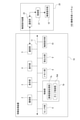
- FIG. 1 It is a block diagram which showed the internal structure example of the information processing apparatus as one Embodiment of the image pickup support control apparatus which concerns on this technique. It is a figure for demonstrating a specific example of the image pickup support method as an embodiment. It is a flowchart which showed the example of the specific processing procedure for realizing the image pickup support method explained with FIG. It is explanatory drawing of the process according to the type of a drawing operation. It is explanatory drawing of the example which displays the name information of a subject type on a screen. It is explanatory drawing of the example which sets the subject within the range drawn on the screen as a target subject. It is explanatory drawing about the setting example of the target composition when a specific mark is drawn in a specific situation.
- Configuration of image pickup support control device as an embodiment> ⁇ 2.
- An example of imaging support method> ⁇ 3.
- Processing procedure> ⁇ 4.
- About the method of specifying the setting conditions of the target composition> ⁇ 5.
- About the method of specifying the subject> ⁇ 6.
- Method of specifying target composition according to the situation> ⁇ 7.
- Correspondence when there are multiple target subjects> ⁇ 8.
- Control according to the movement of the target subject> ⁇ 9.
- Variations on tactile presentation> ⁇ 10.
- FIG. 1 is a block diagram showing an example of an internal configuration of an information processing device 1 as an embodiment of an image pickup support control device according to the present technology.
- the information processing apparatus 1 includes an image pickup unit 2, a display unit 3, an operation unit 4, a communication unit 5, a sensor unit 6, a control unit 7, a memory unit 8, a sound output unit 9, and a tactile presentation unit 10.
- a bus 11 for connecting each of these parts to each other so as to be capable of data communication is provided.
- the information processing device 1 is configured as an information processing device having a camera function, such as a smartphone or a tablet terminal.
- the image pickup unit 2 is configured as a camera unit including an image pickup optical system and an image sensor such as a CCD (Charge Coupled Device) sensor or a CMOS (Complementary Metal Oxide Semiconductor) sensor, and obtains an image captured by digital data.
- the image pickup optical system is provided with a zoom lens, and it is possible to perform optical zoom by driving the zoom lens.
- the image pickup unit 2 includes a camera unit that captures an image in a direction opposite to the direction in which the screen 3a of the display unit 3 described later is directed as a so-called out-camera, and a direction in which the screen 3a is directed as a so-called in-camera. It is also possible to have a configuration including both camera units that capture images in the same direction.
- the display unit 3 is configured to have a display device capable of displaying an image such as an LCD (Liquid Crystal Display) or an organic EL (Electro Luminescence) display, and displays various information on the screen 3a of the display device. ..
- a display device capable of displaying an image such as an LCD (Liquid Crystal Display) or an organic EL (Electro Luminescence) display, and displays various information on the screen 3a of the display device. ..
- the operation unit 4 comprehensively represents operators such as buttons, keys, and a touch panel provided in the information processing device 1.
- the touch panel is formed to detect an operation involving contact with the screen 3a.
- the communication unit 5 performs wireless or wired data communication with the external device of the information processing device 1.
- a communication network such as LAN (Local Area Network) or the Internet
- short-range wireless communication such as Bluetooth (Bluetooth: registered trademark), etc. may be mentioned. can.
- the sensor unit 6 comprehensively represents various sensors included in the information processing apparatus 1.
- the sensor in the sensor unit 6 include a microphone, a G sensor (accelerometer), a gyro sensor (angle velocity sensor), a temperature sensor, a position sensor for detecting the position of the information processing device 1, a proximity sensor, an illuminance sensor, and the like.
- the position sensor include a GNSS (Global Navigation Satellite System) sensor, a geomagnetic sensor for geomagnetic positioning, and the like.
- Wi-Fi positioning using the radio wave strength of Wi-Fi Wi-Fi positioning using the radio wave strength of Wi-Fi (Wireless Fidelity: registered trademark) can also be performed.
- the control unit 7 is configured to include, for example, a microcomputer having a CPU (Central Processing Unit), a ROM (Read Only Memory), and a RAM (Random Access Memory). By executing the corresponding processing, control for realizing various operations and various operations of the information processing unit 1 is performed. For example, the control unit 7 performs various controls on the image pickup unit 2. As an example, for example, an instruction to start or end an imaging operation, an optical zoom control described above, an electronic zoom control, and the like are performed. Further, the control unit 7 controls the output information of the display unit 3, the sound output unit 9, and the information output unit as the tactile presentation unit 10.
- a microcomputer having a CPU (Central Processing Unit), a ROM (Read Only Memory), and a RAM (Random Access Memory).
- control is performed so that the image captured by the image pickup unit 2 is displayed as a through image on the display unit 3 in response to the establishment of a predetermined condition such as activation of a camera application. Further, the display control of the image related to the GUI (Graphical User Interface) is performed in response to the operation input or the like via the operation unit 4.
- GUI Graphic User Interface
- control unit 7 has a function as an image recognition processing unit 7a and a function as a guide control unit 7b as shown in the figure.
- the image recognition processing unit 7a performs image recognition processing on the image captured by the image pickup unit 2.
- the image recognition processing unit 7a includes subject detection processing for detecting an image area having a specific image feature such as face detection or pupil detection as the subject, and the type of the detected subject (the detected subject type 7a). For example, a subject recognition process for recognizing a person, a dog, a cat, a bird, a table, a flower, a bicycle, a car, a ship, a mountain, etc.) and a tracking process for tracking the position of the detected subject are performed.
- the control unit 7 performs a process of displaying information indicating the result of the above image recognition process on the display unit 3 while displaying the through image. For example, information indicating the range of the subject detected by the subject detection process described above (for example, frame information) is displayed on the display unit 3. In addition, information indicating the type of the subject recognized by the subject recognition process can be displayed on the display unit 3.
- the guide control unit 7b controls the image captured by the image pickup unit 2 so that the user guides the composition change operation based on the difference between the target composition and the actual composition. The specific processing performed by the control unit 7 as the guide control unit 7b will be described again.
- the memory unit 8 is composed of, for example, a semiconductor storage device such as a flash memory or a non-volatile storage device such as an HDD (Hard Disk Drive), and various data used for processing by the control unit 7 are stored.
- the memory unit 8 is used as a memory for storing the image captured by the image pickup unit 2.
- the control unit 7 stores one frame image captured at the timing instructed by the shutter operation by the user in the memory unit 8.
- the image data of the moving image obtained by the imaging unit 2 is stored in the memory unit 8 according to the recording start operation.
- the sound output unit 9 is provided with a speaker and outputs various sounds in response to an instruction from the control unit 7.
- the tactile presentation unit 10 includes a tactile presentation device that presents a tactile sensation to a user.
- the tactile presentation unit 10 includes a vibration device as a tactile presentation device, and is capable of presenting a tactile sensation to a user by vibration.
- the guide for the composition change operation by the user is performed by the tactile presentation (vibration in this example) by the tactile presentation unit 10.
- the composition change operation means an operation for changing the composition, such as changing the direction of the camera, changing the positional relationship between the camera and the subject, and zooming.
- the target composition is a composition that satisfies the condition that the target subject is arranged at the target position in the image frame according to the target size.
- the target composition is set based on the user's operation input. Further, in this example, it is assumed that the user specifies the target subject.
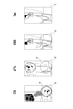
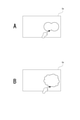
- FIG. 2A is a diagram for explaining an example of a method for designating a target subject.
- a mark indicating the range of the detected subject is displayed as shown by the broken line mark in the figure. Will be done.
- the guide control unit 7b in the control unit 7 accepts an operation (for example, a touch operation) for designating a mark indicating the range of the detected subject displayed in this way as a designation operation for the target subject.
- FIG. 2B and 2C are diagrams for explaining an example of a target area At designation operation as an area where the target subject should be accommodated.
- the operation of designating the target area At is an operation of drawing a circle on the screen 3a as shown in FIG. 2B.
- the guide control unit 7b sets the range designated by such a drawing operation as the target area At (see FIG. 2C).
- the center position of the target area At is set as the target position Pt
- the position Ps of the target subject matches the target position Pt
- the size of the target subject is designated as the target area At.
- a composition that satisfies the condition that the target size is based on the size is set as the target composition.
- the target size of the target subject is assumed to be the same as the size specified as the target area At. It is not essential that the size of the target subject exactly matches the size specified as the target area At, for example, the target is within ⁇ 10% of the size specified as the target area At. It can also be set as a size and subject to this target size.
- the guide control unit 7b makes it possible to perform a guide for realizing the target composition according to the setting of the target area At according to the user operation.
- the size of the target subject is adjusted by the guide control unit 7b performing the zoom control of the image pickup unit 2. That is, in this example, since the size adjustment of the target subject is automatically performed on the information processing apparatus 1 side, the guide related to the size of the target subject is not performed.
- the position Ps of the target subject is sequentially grasped (for example, for each frame) by the tracking process by the image recognition processing unit 7a, and the guide control unit 7b is the position regarding the target position Pt and the position Ps of the target subject. Recognize the relationship.
- the guide control unit 7b guides the change of the direction of the information processing apparatus 1 (camera) from the positional relationship that is sequentially recognized in this way.
- the guide at this time is performed by changing the mode of tactile presentation based on the size of the difference between the target composition and the actual composition.
- the mode of vibration is changed according to the distance between the position Ps of the target subject and the target position Pt. For example, as the distance between the position Ps of the target subject and the target position Pt decreases, the vibration cycle is shortened.
- a first threshold value and a second threshold value are set for the separation distance between the position Ps of the target subject and the target position Pt, and the separation distance is the first threshold value.
- the number of vibrations per unit time is once when the distance exceeds the first threshold value, and the number of vibrations per unit time is twice when the separation distance is equal to or less than the first threshold value and exceeds the second threshold value.
- an example may be given in which the number of vibrations per unit time is set to 3 times.
- the user By performing the vibration control as described above, the user approaches the target composition in the process of changing the direction of the information processing apparatus 1 even in the situation where the image is taken without gazing at the screen 3a. It becomes possible to easily grasp whether or not the person is moving away, and it becomes easier to match the target composition.
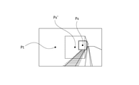
- FIG. 2D illustrates the state of the screen 3a when the target composition is achieved. That is, in this example, it is a state when the position Ps of the target subject coincides with the target position Pt.
- the achievement condition of the target composition is that the distance between the position Ps of the target subject and the target position Pt is equal to or less than a predetermined threshold value other than 0, or the position Ps of the target subject and the target position Pt match per unit time.
- Other conditions can be set, such as setting the achievement condition of the target composition that the number of times reaches a predetermined number of times.
- the guide control unit 7b causes the tactile presentation unit 10 to execute a notification to that effect.
- the notification when the target composition is achieved is made to be different from the tactile presentation for the guide when the target composition is not achieved.
- the user performs the shutter operation upon receiving the notification of the achievement of the target composition as described above. This makes it possible to capture a still image with the target composition.
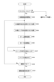
- FIG. 3 The process shown in FIG. 3 is executed by the control unit 7 (CPU) based on a program stored in a predetermined storage device such as a built-in ROM.
- the control unit 7 starts the process shown in FIG. 3, for example, in response to the activation of the camera application.
- control unit 7 determines in step S101 whether or not it is in the guide mode. That is, it is determined whether or not the mode enables the guide function for the composition change operation described above. If it is not the guide mode, the control unit 7 shifts to the normal mode processing. That is, the process shifts to the process for imaging without a guide.
- control unit 7 starts the image recognition process in step S102. That is, the processing as the image recognition processing unit 7a described above is started, and the subject detection processing, the subject recognition processing, and the subject tracking processing are performed.
- step S103 following step S102 the control unit 7 performs a designation acceptance process for the target subject. That is, the operation of designating the mark indicating the range of the detected subject displayed on the screen 3a in the subject detection process is accepted.
- the control unit 7 When the designation operation of the object subject is detected, the control unit 7 performs the designation acceptance process of the target area At in step S104. That is, in this example, the drawing operation of the circle on the screen 3a as illustrated in FIG. 2B is accepted.
- the control unit 7 sets the target position Pt (in this example, it is set at the center position of the target area At).
- step S105 the control unit 7 executes the zoom adjustment process. That is, zoom control is performed on the image pickup unit 2 so that the size of the target subject in the captured image matches the size of the target area At.
- step S106 the control unit 7 starts the guide process. That is, based on the positional relationship between the target position Pt and the position Ps of the target subject, which are sequentially recognized based on the tracking process of the target subject, the guide of the composition change operation is controlled so as to be performed by the vibration presentation of the tactile presentation unit 10. Specifically, in this example, guidance is performed by changing the mode of vibration according to the separation distance between the position Ps of the target subject and the target position Pt. For example, as illustrated above, it is conceivable to perform control to shorten the vibration cycle as the distance between the position Ps of the target subject and the target position Pt becomes smaller.
- the tactile presentation unit 10 Notification to that effect will be given by the vibration presentation by.
- step S107 the control unit 7 waits until the shutter operation is detected, and when the shutter operation is detected, the guide process is terminated in step S108 and the process proceeds to step S109.
- step S109 the control unit 7 determines whether or not the imaging is completed. That is, it is determined whether or not a predetermined condition predetermined as an imaging end condition such as detection of an end operation of the camera application is satisfied. For example, if the end operation of the camera application is not detected and it is determined that the imaging is not completed, the control unit 7 returns to step S103. As a result, for the next still image imaging, designation acceptance of the target subject and the target area At, zoom adjustment processing and guide processing based on the designated target subject and the target area At are performed.
- step S109 if it is determined in step S109 that the imaging is completed, the control unit 7 ends the image recognition process in step S110 and ends the series of processes shown in FIG.
- the guide function as an embodiment can be suitably applied to when capturing a moving image.
- the guide for the composition change operation for adjusting the size of the target subject and the target area At is not performed, but for such size adjustment.
- both the alignment of the target subject and the target area At and the guide of the size are performed, it is conceivable to perform vibration for the guide in a time-division manner. For example, it is conceivable to assign the first half period within the unit period to the guide for alignment and the second half period to the guide for size adjustment.
- both guides can be performed by a method other than time division, such as expressing the alignment guide by the vibration intensity and the size alignment guide by the number of vibrations per unit time.
- the direction guide may be performed in four directions of up, down, left, and right, or may be performed only in two directions of vertical and horizontal.
- the operation of designating the target area At that is, the operation related to the setting of the arrangement position in the image frame of the target subject is the operation of drawing a circle on the screen 3a. It is also possible to determine the type of drawing operation for the target composition, and to determine the setting condition excluding the arrangement position of the target subject among the setting conditions of the target composition according to the type of such drawing operation.
- the setting condition of the target composition means a condition for determining what kind of composition the target composition should be, for example, the arrangement position of the target subject in the image frame and the target subject. The conditions of singular or plural can be mentioned.
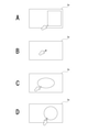
- Examples of the type of drawing operation include drawing a quadrangle as shown in FIGS. 4A to 4D, drawing a point, drawing an ellipse, drawing a circle by multi-touch by two-finger touch, and the like.
- the setting conditions excluding the placement position of the target subject among the setting conditions of the target composition are defined.
- the guide control unit 7b sets a target composition setting condition (arrangement of the target subject) corresponding to the type of the drawing operation performed by the user according to which of the plurality of predetermined types belongs. (Excluding the position setting conditions) is determined.
- the condition that the whole body of the subject is included in the quadrangle is determined as a setting condition of the target composition.
- the target composition is not based on the size of the target subject, but on the condition that the position of the point is set as the target position Pt and the target subject is placed at the target position Pt. Determined as the setting condition of.
- the ellipse is drawn as shown in FIG. 4C, the condition that a plurality of target subjects are arranged in the ellipse is determined as the setting condition of the target composition.
- the circle is drawn by multi-tap as shown in FIG.
- the condition that the target subject is arranged in the circle is determined as the setting condition of the target composition without the condition of the size of the target subject. ..
- the size of the target subject is matched with the size of the circle, and the target subject is set at the target position Pt determined from the drawing area of the circle. It can be said that this is an example of determining the condition of placement as the setting condition of the target composition.
- the user can specify the placement position of the target subject and set the setting conditions excluding the placement position among the setting conditions of the target composition.
- the designation can be performed by one operation as a drawing operation for the screen 3a. Therefore, it is possible to reduce the user operation burden.
- the control unit 7 is configured so that the type name of the subject that can be recognized by the subject recognition process described above can be identified by voice, and the pronunciation of the type name of the subject that can be recognized by the subject recognition process is recognized. Then, the subject belonging to the type is determined as the target subject.
- the process of determining the target subject based on the input voice can be performed at a stage where the subject has not yet been detected in the captured image.
- the user when it is desired to target a dog or a child as a target subject, the user can detect the presence of the dog or a child nearby from surrounding sounds or the like, so that the target subject is detected in the image (in the image frame). Regardless of whether or not it is, it is effective to accept the target subject designation by voice.
- the target subject before detection is specified, the subject is set as the target subject according to the fact that the subject of the corresponding type is detected in the image.
- the designation acceptance of the target subject can be performed by displaying the name information of the type of the candidate subject and the mark indicating the range thereof, as illustrated in FIG. 5, for example.
- the guide control unit 7b displays on the screen 3a a mark indicating the range and name information of the type of the detected subject whose type can be recognized.
- the designation acceptance of the target subject as illustrated in FIG. 6, it is also possible to accept the drawing operation of the range with respect to the screen 3a.
- the subject within the drawn range is set as the target subject.
- Such an acceptance method is a suitable method when the object that the user wants to be the target subject cannot be detected by the subject detection process.
- the method illustrated in FIG. 6 may be inferior in tracking robustness, improvement can be expected by using background subtraction and optical flow methods.
- the target subject is specified by the range drawing operation as shown in FIG. 6, in order to make the user identify whether the target area At is specified in the acceptance state or the target subject is in the acceptance state. It is conceivable to give a notification of.
- the information indicating the subject type that can be recognized by the subject recognition process can be displayed in a list on the screen 3a and accepted as the designation from among them.
- an error notification may be performed. This notification is made, for example, by vibration presentation by the tactile presentation unit 10.
- the setting of the target composition according to the user's operation is not limited to the specific examples exemplified so far.
- the situation of the information processing apparatus 1 functioning as a camera is determined, the situation is a specific situation, and a specific mark is drawn by a drawing operation on the screen 3a, the situation and the drawn mark are used. It is also possible to set a composition that satisfies the composition conditions associated with the target composition as a target composition.
- FIG. 7 when the information processing apparatus 1 is located in a specific theme park and a mark imitating a specific character in the theme park is drawn on the screen 3a, the character is drawn.
- This is an example of setting a composition that is placed at a position within the image frame corresponding to the mark as a target composition.
- a star mark is drawn on the screen 3a in a situation where the information processing device 1 is directed to the sky outdoors, the brightest star is within the range of the star mark.
- the composition in which is arranged is set as the target composition.
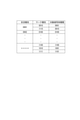
- the subject identification information I1 as illustrated in FIG. 8 is stored in the storage device that can be read by the control unit 7 such as the memory unit 8. Will be done.
- the guide control unit 7b determines whether or not the situation of the information processing apparatus 1 is a predetermined specific situation. For example, in the case of FIG. 7, it is determined whether or not the situation is located in a specific theme park. This determination can be made, for example, based on the detection signal of the position sensor in the sensor unit 6. Further, in the above-mentioned star example, it is determined whether or not the information processing apparatus 1 is directed to the sky outdoors.
- This determination can be made based on, for example, the detection signal of the position sensor or the microphone in the sensor unit 6 and the detection signal of the G sensor or the gyro sensor. By making such a determination, the guide control unit 7b recognizes the type of the situation in which the information processing apparatus 1 is placed.
- the guide control unit 7b determines whether or not the drawn mark is a specific mark when a drawing operation is performed on the screen 3a. For example, in the example of FIG. 7, it is determined whether or not the mark imitates a specific character, and in the above-mentioned star example, it is determined whether or not the mark is a star-shaped mark. By making such a determination, the guide control unit 7b recognizes the type of the drawn mark.
- the subject identification information I1 is associated with information indicating the type of the target subject for each combination of the situation type and the mark type, and the guide control unit 7b is associated with the situation type and the mark type as described above.
- the guide control unit 7b sets the subject specified from the subject type information obtained by referring to the information processing apparatus 1 as the target subject, and the target subject is within the range of the mark drawn on the screen 3a.
- the composition that satisfies the condition that is placed is set as the target composition.
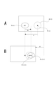
- FIG. 9 illustrates a situation in which a plurality of target subjects as “dogs” are detected in the image frame of the captured image.
- a drawing operation for specifying a range is performed so as to have two bulging portions on the screen 3a as shown in FIG. 10A
- two target subjects out of a plurality of detected target subjects are within the specified range.
- the drawing operation for specifying the range is performed so as to have a predetermined number or more (for example, at least 3 or more) of bulges as shown in FIG. 10B
- all of the detected plurality of target subjects are specified as the specified range.
- the guide control unit 7b determines which operation type the drawing operation belongs to among the plurality of operation types. Accordingly, the number of target subjects to be arranged within the arrangement range can be determined.
- the user can specify the placement range of the target subject and place the target subject within the placement range. It is possible to specify the number of target subjects by one operation as a drawing operation for the screen 3a. Therefore, it is possible to reduce the user operation burden.
- the user can estimate whether or not there are a plurality of objects as target subjects in the surroundings from the surrounding conditions (visual sense, sound, etc.). For example, it is possible to estimate whether there are a plurality of dogs from the bark of a dog and the voice of a child. From this point, regarding the acceptance of the designation of the placement range of the target subject and the determination of the number of placements of the target subject according to the type of drawing operation for specifying the placement range, the target subject is not detected in the captured image. You can also do it.
- the target subject While executing the guide for arranging a plurality of target subjects in the specified arrangement range, if there is a target subject that is partly away from other target subjects, the target is close to the arrangement range. Only the subject may be tracked.
- the size of the arrangement range specified by the user it may be dynamically determined which subject among the plurality of target subjects is to be the tracking target for the guide. For example, in the case of two target subjects, if the image size of the specified arrangement range is smaller than a predetermined size such as 100 pixels ⁇ 100 pixels, one target subject is used for guiding, otherwise two target subjects are used for guiding. It may be a tracking target.
- the subject closest to the arrangement range among the plurality of target subjects detected in the image is selected. It is conceivable to set it as a tracking target for the guide.
- the characteristics of the plurality of target subjects for example, coat color, size, etc. in the case of a dog
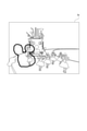
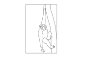
- Control according to the movement of the target subject Various controls can be considered as controls according to the movement of the target subject. For example, it is conceivable to estimate the moving direction of the target subject from the image analysis of the captured image and guide how to hold the information processing device 1 (camera) according to the direction. Specifically, for example, in the case of a scene in which a monkey climbs a tree as shown in FIG. 11, a guide instructing the user to hold the monkey vertically as shown in FIG. 12 is performed. Further, in the case of a scene in which a crab moves as shown in FIG. 13A or a scene in which a child walks around as shown in FIG. 13B, a guide instructing the user to hold the crab as illustrated in FIG. 14 is performed.
- the direction in which the target subject moves can be estimated from, for example, the direction and amount of the background flowing in the captured image.
- guide control for detecting the movement of the target subject and arranging the target subject at the target position Pt based on the detected movement of the target subject is performed. You can also do it.
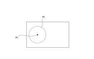
- FIG. 15A illustrates the relationship between the position Ps (t) of the target subject, the target area At (t), and the target position Pt (t) at a certain time (t).
- the separation distance between the position Ps (t) of the target subject and the target position Pt (t) is defined as “d”.
- the amount of movement of the target subject during the predetermined period is set to "do" as shown in the figure at the time point (t + 1) after the elapse of the predetermined period from the time (t), the user faces the camera according to the guide at the time point (t).
- the image frame side is moved by "di" as shown in FIG. 15B, the target subject also moves by "do", so the position Ps (t + 1) of the target subject is placed at the target position Pt (t + 1). Will be difficult.
- the movement amount "de” of the target subject between each frame is calculated over the past plurality of frames of the captured image, and the guide is performed based on the movement amount de. It is not a simple average, but a constant velocity, acceleration, and deceleration are calculated in an identifiable manner.
- the movement amount de is a vector quantity having a distance and a direction.
- the guide control unit 7b sets "d-de” as the target value of the movement amount on the image frame side when the target subject is moving in the direction approaching the target position Pt, and moves the camera too much to the user. Control to be guided to request no.
- the guide control unit 7b sets "d + de” as the target value of the movement amount on the image frame side, and guides the user to move the camera more. Control to be done.
- the guide control unit 7b obtains the movement amount of the target subject based on, for example, captured images for a plurality of past frames, and predicts the position of the target subject after a predetermined time from the movement amount. Then, the guide is performed based on the relationship between the position predicted in this way and the target position Pt. Specifically, for example, it is conceivable to perform a guide that changes the mode of vibration according to the magnitude of the separation distance between the predicted position and the target position Pt.
- the target composition is set by the guide control unit 7b based on the determination result of the scene to be imaged.
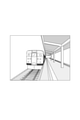
- the optimum composition is predetermined for the scene to be imaged in which the train as illustrated in FIG. 16 exists on the platform of the station.
- a composition in which the target subject is a train and the target area At (target position Pt) is set as shown in FIG. 17 is defined as the target composition.
- a plurality of combinations of the imaging target scene and the optimum composition are defined.
- the guide control unit 7b determines the current image capture target scene by image analysis processing or the like of the image captured by the image pickup unit 2.
- the method for determining the scene to be imaged is not particularly limited.
- a method using AI (artificial intelligence) learned to classify scenes from images can be mentioned.
- the guide control unit 7b sets the optimum composition determined for the determined imaging target scene as the target composition.
- the guide control unit 7b performs a process for guiding.
- the guide is not performed based on the current position of the target subject, but is performed based on the position where the target subject is in the target state, which is determined according to the scene to be imaged.
- the target state here means the target state of the target subject determined according to the scene to be imaged. Specifically, it means, for example, a state in which a shutter chance occurs.
- the state in which the train as the target subject is stopped is defined as the target state.
- the guide control unit 7b predicts the position Ps'in which the subject as a train is in the target state, that is, the stopped state from the current captured image, and the predicted position Ps'
- the tactile presentation unit 10 is controlled so that a guide for being arranged at the target position Pt is performed.
- the position (Ps') at which the train is stopped at the platform of the station can be estimated from the position of the stop line of the train, for example, by detecting the image of the stop line of the train at the platform.
- the speed of the train may be calculated from the captured image, and the position where the train is stopped may be estimated based on the speed. In estimating the stop position based on such speed, the information on the distance to the train is used, but the information on the distance may be calculated by using the time difference of the captured image, or the distance measuring sensor may be used. It may be obtained by using it separately.
- the shutter may be automatically released (the captured image of the still image is stored in the memory unit 8) on condition that the target subject is within the target area At.
- the size of the target area At may be set to a size based on the size of the train when the train reaches the stop position.
- a scene related to a train is illustrated as an example of a scene to be imaged, but a guide can be performed by the same method for a sunset scene as illustrated in FIG. 19A, for example.
- a composition in which the target subject is the sun and the target area At (target position Pt) is set as shown in FIG. 19B is defined as the target composition.
- a state in which the sun sets is defined as a target state of the target subject.
- the current time information can also be used to determine whether or not the scene is a scene to be imaged at sunset.
- the guide control unit 7b predicts the position Ps'where the target subject is in the target state, that is, the position where the sun sets, from the current captured image as illustrated in FIG. 19A.
- the position where the sun sets can be predicted by obtaining the movement trajectory of the sun from the captured image within a certain period in the past and based on the movement trajectory.
- the guide control unit 7b in this case is tactile so that a guide is performed so that the predicted position Ps'is placed at the target position Pt.
- the presentation unit 10 is controlled.
- the target composition for each scene to be imaged may be determined based on the result of analyzing the composition of a large number of captured images uploaded on the Internet, such as the captured image posted on the SNS (Social Networking Service) site. can.
- the user's favorite composition can be learned and determined based on the result of analyzing the composition of the past captured image by the user.
- vibration for the guide not only the vibration for the guide but also other information can be notified by vibration at the same time.
- the distance between the position Ps of the target subject and the target position Pt by vibration it is conceivable to notify the intensity of the movement of the subject by vibration.
- the distance from the target position Pt is expressed by the difference in vibration frequency, and the amount of movement between the frames of the subject is expressed by the intensity of vibration.
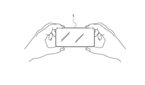
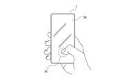
- the vibration for the guide can be performed in the form of screen vibration as illustrated in FIG.
- the target position Pt is specified by touching the screen 3a and then the finger is kept touching the screen 3a, and after the target position Pt is specified, guidance is performed by screen vibration.
- the vibration intensity for example, the vibration becomes stronger as it gets closer.
- a piezo element may be used as the vibration device in this case.
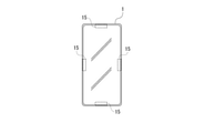
- vibration devices 15 arranged on the upper, lower, left and right sides of the information processing apparatus 1.
- the user can be notified in which direction the information processing apparatus 1 should be moved, depending on which position the vibrating device is vibrated.
- the guide function for the composition change operation can be enabled or disabled based on the user operation. For example, on a smartphone, it is conceivable to enable the guide function when an operation of setting the "visually impaired mode" is performed in the accessibility item in the "setting" menu.
- the hand may be raised high to take an image, and in such a case, the image is taken without looking at the screen 3a. Therefore, it is assumed that the estimation of whether or not the user raises his / her hand to perform imaging is performed as the estimation of whether or not the user is not looking at the screen 3a, and the user raises his / her hand to perform imaging. Enable the guide function when estimated.
- the user raises his / her hand it is possible to estimate whether or not the user raises his / her hand to perform imaging, for example, based on the captured image of the in-camera and the detection signal by the G sensor or the gyro sensor in the sensor unit 6. Alternatively, it can be performed by using the detection signal by the height sensor.
- the estimation of whether or not the user is not looking at the screen 3a can be performed, for example, as the estimation of whether or not the user's line of sight is directed to the screen 3a. Whether or not the user's line of sight is directed to the screen 3a can be estimated based on, for example, an image captured by the in-camera.
- the guide function it is also conceivable to enable the guide function according to the recognition of a specific type of subject from the captured image. Alternatively, it is conceivable to enable the guide function according to the determination that the movement of the subject is large. Further, the activation condition of the guide function may be these AND conditions. For example, if the "child" is recognized as the subject and the movement of the subject is large, the guide function is enabled.
- the target composition requires that the size of the target subject be adjusted to the target size, the size of the target subject is too large or too small for the target size, and the size adjustment by zooming is the target. There may be cases where the size cannot be adjusted. When the zoom cannot be further performed or when it is predicted that the target size cannot be adjusted by the size adjustment by the zoom, it is conceivable to notify the user by the tactile presentation of the tactile presentation unit 10.
- step S105 when the user determines that the size of the target subject cannot be set to the target size by the zoom control, the user An example of determining whether or not the situation can be moved and notifying the error when it is determined that the situation cannot be moved will be described.
- a guide for changing the positional relationship between the user and the target subject is performed.
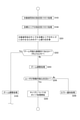
- FIG. 22 shows an excerpt of a part of the processing to be executed after step S103 in the processing shown in FIG.
- the control unit 7 sets the size of the target subject to the size of the target area At in step S201.
- This zoom value is obtained as a value within the zoomable range (for example, 35 mm to 100 mm, etc.).
- step S202 following step S201 the control unit 7 determines whether or not it is within the zoomable range. Specifically, it is determined whether or not the zoom value Td described above is within the range of the minimum zoom value TR or more and the maximum zoom value TE or less described below.
- the minimum zoom value TR is the minimum value in the zoomable range
- the maximum zoom value TE is the maximum value in the zoomable range.
- the maximum zoom value TE is set to the maximum value in the zoomable range by the optical zoom.
- the maximum zoom value TE may be determined in consideration of image quality deterioration due to digital zoom. The condition that the image quality becomes coarse due to the digital zoom and it becomes impossible to recognize what kind of object is different depending on the brightness, environment, type of subject, and user's visual acuity, so the maximum zoom value TE is adaptively according to those conditions, for example. It may be determined.
- step S202 If it is determined in step S202 that the range is within the zoomable range, the control unit 7 proceeds to step S105 to execute the zoom adjustment process. In this case, the processes after step S105 shown in FIG. 3 are executed to guide the position Ps of the target subject to the target position Pt.
- step S202 determines that the range is not within the zoomable range
- the control unit 7 performs the zoom adjustment process in step S203.
- the zoom adjustment process is performed to adjust to the minimum zoom value TR (when it is large with respect to the target size) or the maximum zoom value TE (when it is small with respect to the target size).
- step S204 the control unit 7 determines whether or not the user can move. That is, it is determined whether or not the situation is such that the user cannot move forward or backward by taking an image in a crowded place, for example. Whether or not the user can move is determined based on, for example, analysis of the captured image by the imaging unit 2, detection sound by the microphone in the sensor unit 6, (environmental sound around the information processing device 1), and the like. Can be done.
- step S204 If it is determined in step S204 that the user can move, the control unit 7 proceeds to step S205 to start the guide process for the size. That is, the guide for adjusting the size of the target subject to the target size is controlled so as to be performed by the tactile presentation of the tactile presentation unit 10. As this guide, the user decides whether to move the information processing apparatus 1 forward (in the direction closer to the target subject) or backward, at least depending on whether the size of the target subject is smaller or larger than the target size. Make sure it is done in a recognizable form. After starting the guide processing for the size in step S205, the control unit 7 may proceed to the processing in step S107 shown in FIG.
- step S204 If it is determined in step S204 that the user is not in a movable situation, the control unit 7 executes error notification processing in step S206. That is, the user is notified that the size of the target subject cannot be adjusted to the target size. It is conceivable that this notification is executed by the tactile presentation of the tactile presentation unit 10. In the error notification process in step S206, a notification urging the user to change the size of the target area At may be given.
- the control unit 7 determines whether or not the user can move when it is determined that the size of the target subject cannot be set to the target size by the zoom control.
- a guide is provided to change the positional relationship between the user and the target subject.
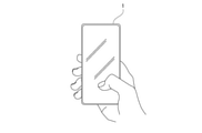
- finger fogging means a state in which at least a part of the finger of the user holding the camera touches the lens or the like to block at least a part of the imaging field of view.
- the presence or absence of finger fogging can be determined, for example, from a captured image.
- whether or not the camera shake is large can be determined from the detection signal by the G sensor or the gyro sensor in the sensor unit 6 or the captured image (for example, the difference between frames).
- the presence or absence of out-of-focus can be determined as to whether or not AF (autofocus) is performed on the specified target subject.
- the tactile presentation unit 10 When the control unit 7 determines that such a situation of finger fogging, out-of-focus, or large camera shake has occurred, the tactile presentation unit 10 performs a predetermined notification as an error notification by the tactile presentation.
- out-of-focus it is conceivable to issue different notifications according to the type of cause. For example, different error notifications are given depending on whether the problem is solved by the user moving the position or the target subject needs to be redesignated. In this case, the action to be taken by the user can be notified by tactile presentation, sound, or the like.
- the error notification it is also possible to notify that a specific object (for example, a dangerous object: a bicycle, a car, etc.) is detected in the captured image during the guide (for example, a tactile presentation is performed).
- a specific object for example, a dangerous object: a bicycle, a car, etc.
- the embodiment is not limited to the specific example described above, and can be configured as an embodiment modification.
- the in-camera recognizes the type of user and switches various settings of the information processing apparatus 1.
- the user is an elderly person, it is conceivable to set the shutter speed to be increased in order to prevent camera shake.
- the user is an elderly person, it is conceivable to set the vibration intensity at the time of guiding to be increased.
- the UI User Interface
- the English version may be changed to the English version.
- the vibration device for the guide and the camera for obtaining the captured image are mounted on an integrated device as the information processing device 1
- the vibration device for the guide is described. It is not limited to being mounted on a device integrated with a camera that obtains an captured image.
- the tactile presentation device 20 that presents vibration for a guide is separated.
- FIG. 23 the same reference numerals are given to the parts that are the same as the parts that have been explained so far, and the description thereof will be omitted.
- the image pickup support system 100 includes an information processing device 1A and a tactile presentation device 20.
- the tactile presentation device 20 includes a tactile presentation unit 10, a control unit 21, and a communication unit 22.
- the information processing apparatus 1A is different from the information processing apparatus 1 shown in FIG. 1 in that the control unit 7A is provided in place of the control unit 7.
- the communication unit 5 is configured to be capable of performing data communication with the communication unit 22 in the tactile presentation device 20.
- the control unit 7A is different from the control unit 7 in that it has a guide control unit 7bA instead of the guide control unit 7b.
- the guide control unit 7bA controls so that the guide for the composition change operation is performed by the tactile presentation by the tactile presentation unit 10 in the tactile presentation device 20.
- a tactile presentation instruction for a guide is given to the control unit 21 via the communication unit 5, and the control unit 21 causes the tactile presentation unit 10 in the tactile presentation device 20 to execute the tactile presentation according to the instruction. ..
- the device form of the tactile presentation device 20 for example, a device form worn by the user, such as a smart watch or a glasses-type information processing device capable of communicating with the information processing device 1A such as a smartphone or a tablet terminal.
- a device form such as a stand device such as a tripod that supports the information processing device 1A that functions as a camera can be considered.
- the information processing device 1A has the tactile presentation unit 10.
- vibration has been exemplified as an example of tactile presentation for a guide, but as tactile presentation, for example, presentation other than vibration such as blowing air can be performed.
- the guide for the composition change operation by the user is performed by tactile presentation to the user based on the difference between the target composition and the actual composition. It is provided with a control unit (guide control units 7b, 7bA) for controlling the information processing.
- guide control units 7b, 7bA for controlling the information processing.
- the control unit changes the mode of tactile presentation for the guide based on the size of the difference between the target composition and the actual composition. This makes it possible for the user to grasp whether the difference between the target composition and the actual composition is small or large by the difference in the mode of tactile presentation for the guide. Therefore, even in a situation where the user cannot or is difficult to see the screen, it is possible to increase the ease of adjusting to the target composition and improve the imaging support performance.
- the target composition is a composition that satisfies the condition that the target subject is arranged at a position determined by the user operation in the image frame, and the target composition is arranged in the image frame of the target subject.
- the operation related to the position setting is performed as a drawing operation on the screen (3a) for displaying the through image of the captured image, and the control unit determines which of the plurality of operation types the drawing operation belongs to. Therefore, the setting conditions excluding the placement position among the setting conditions of the target composition are determined.
- the operation type of the drawing operation is a type of operation that can be performed as a drawing operation, and examples thereof include an operation of drawing a point, an operation of drawing a circle, and an operation of drawing an ellipse.
- the setting condition of the target composition means a condition for determining what kind of composition the target composition should be, for example, the arrangement position of the target subject in the image frame and a single target subject. Conditions such as whether to use or to have a plurality of items can be mentioned. According to the above configuration, the user can specify the placement position of the target subject and the setting conditions other than the placement position among the setting conditions of the target composition by one operation as a drawing operation on the screen. It becomes. Therefore, it is possible to reduce the user operation burden.
- the target composition is a composition that satisfies the condition that the target subject is arranged at a position determined by the user operation in the image frame, and the control unit is the target subject.
- the designation is accepted by voice input from the user. This eliminates the need for the user to operate an operator such as a button or a touch panel when designating the target subject. Therefore, when designating the target subject, it is not necessary for the user to search for the target subject on the screen or to search for the operator for designation, which is suitable for taking an image without gazing at the screen. In particular, a user interface suitable for the visually impaired can be realized.
- the control unit accepts a drawing operation on the screen for displaying the through image of the captured image, determines the situation of the camera that obtains the captured image, and the situation is a specific situation. And when a specific mark is drawn by the drawing operation, a composition satisfying the composition condition associated with the situation and the drawn mark is set as the target composition.
- a specific mark for example, a mark imitating a famous character in the theme park is drawn.
- compositions that satisfies the composition conditions associated with the situation and the mark as the target composition, such as a composition in which the character is placed at a position in the image frame corresponding to the drawn mark. be. Therefore, it is possible to perform a plurality of composition setting conditions by one operation of drawing a mark, and it is possible to reduce the burden on the user operation.
- the target composition is a composition that satisfies the condition that the target subject is arranged at a position determined by the user operation in the image frame, and the target composition is arranged in the image frame of the target subject.
- the range designation operation is performed as a drawing operation on the screen for displaying the through image of the captured image, and the control unit is within the arrangement range according to which of the plurality of operation types the drawing operation belongs to.
- the number of target subjects to be placed is determined. As a result, the user can specify the arrangement range of the target subject and the number of target subjects to be arranged within the arrangement range by one operation as a drawing operation on the screen. Therefore, it is possible to reduce the user operation burden.
- the target composition is a composition that satisfies the condition that the target subject is placed at the target position in the image frame, and the control unit detects the movement of the target subject.
- the guide for arranging the target subject at the target position is controlled based on the detected movement of the target subject. This makes it possible to perform a guide in consideration of the movement of the target subject as a guide for realizing the composition of arranging the target subject at the target position in the image frame. Therefore, it is possible to improve the accuracy of the guide in response to the case where the target subject is a moving subject.
- the control unit guides the target subject based on the relationship between the predicted position and the target position after a predetermined time.
- the guide is performed based on the difference between the current position of the target subject and the target position, and the position of the target subject is set to the target position.
- the guide is performed based on the position after a predetermined time predicted from the movement of the target subject. Therefore, it is possible to improve the accuracy of the guide in response to the case where the target subject is a moving subject.
- the control unit sets the target composition based on the determination result of the image pickup target scene. This makes it possible to automatically set a target composition according to the scene to be imaged, such as a scene in which a train is imaged at a station or a scene in which a sunset is imaged, based on a scene determination result. Therefore, it is possible to reduce the operational burden on the user when performing imaging with an appropriate target composition according to the scene to be imaged.
- the target composition is a composition that satisfies the condition that the target subject is placed at the target position in the image frame.
- the control unit The position where the target subject is in the target state according to the image capture target scene is predicted, and the guide is controlled so that the predicted position matches the target position. This makes it possible to appropriately support the user so that the target subject in the target state is captured by the target composition. Therefore, it is possible to improve the user support performance related to the composition change at the time of imaging.
- the control unit enables the guide function when it is estimated that the user is not looking at the screen displaying the through image of the captured image.
- the guide according to the present embodiment is automatically performed in a situation where the user performs imaging without looking at the screen. Therefore, it is possible to appropriately support the user. Further, it is possible to prevent the guide function from being enabled even when the guide is unnecessary, such as when the user performs an image while looking at the screen, and the convenience can be improved.
- the target composition is a composition that satisfies the condition that the target subject is arranged at the target position in the image frame according to the target size
- the control unit is the size of the target subject.
- the zoom is controlled so that is the target size. This makes it possible to eliminate the need for a zoom operation by the user in order to realize imaging with a target composition. Therefore, it is possible to reduce the user operation burden.
- the control unit determines whether or not the user can move when it is determined that the size of the target subject cannot be set to the target size by the zoom control.
- a guide is provided to change the positional relationship between the user and the target subject.
- the information processing apparatus controls so that the guide for the composition change operation by the user is performed by tactile presentation to the user based on the difference between the target composition and the actual composition.
- This is an imaging support control method. Even with such an image pickup support control method, the same operations and effects as those of the image pickup support control device as the above-described embodiment can be obtained.
- the imaging support system (100) as an embodiment is based on a tactile presentation device (20) having a tactile presentation unit (10) that presents a tactile sensation to a user, and a difference between a target composition and an actual composition. It is provided with an image pickup support control device (information processing device 1A) having a control unit (guide control unit 7bA) that controls the guide for the composition change operation by the user so as to be performed by the tactile presentation of the tactile presentation unit. ..
- an image pickup support control device information processing device 1A
- guide control unit 7bA control unit that controls the guide for the composition change operation by the user so as to be performed by the tactile presentation of the tactile presentation unit.
- An image pickup support control device provided with a control unit that controls so that a guide for a composition change operation by a user is performed by tactile presentation to the user based on the difference between a target composition and an actual composition.
- the control unit The imaging support control device according to (1) above, which changes the mode of tactile presentation for the guide based on the magnitude of the difference between the target composition and the actual composition.
- the target composition is a composition that satisfies the condition that the target subject is placed at a position determined according to the user operation in the image frame.
- the operation related to the setting of the arrangement position of the target subject in the image frame is performed as a drawing operation on the screen for displaying the through image of the captured image.
- the control unit Described in (1) or (2) above, the setting conditions excluding the arrangement position among the setting conditions of the target composition are determined according to which operation type the drawing operation belongs to among the plurality of operation types.
- Imaging support control device (4)
- the target composition is a composition that satisfies the condition that the target subject is placed at a position determined according to the user operation in the image frame.
- the control unit The imaging support control device according to any one of (1) to (3) above, which accepts the designation of the target subject by voice input from the user.
- the control unit While accepting drawing operations on the screen that displays the through image of the captured image, When the situation of the camera that obtains the captured image is determined and the situation is a specific situation and the specific mark is drawn by the drawing operation, the situation is associated with the drawn mark.
- the image pickup support control device according to any one of (1) to (6) above, wherein a composition satisfying the composition condition is set as the target composition.
- the target composition is a composition that satisfies the condition that the target subject is placed at a position determined according to the user operation in the image frame.
- the operation of designating the arrangement range of the target subject in the image frame is performed as a drawing operation on the screen for displaying the through image of the captured image.
- the control unit The description according to any one of (1) to (5) above, wherein the number of the target subjects to be arranged within the arrangement range is determined according to which operation type the drawing operation belongs to among the plurality of operation types. Imaging support control device.
- the target composition is a composition that satisfies the condition that the target subject is placed at the target position in the image frame.
- the control unit The description according to any one of (1) to (6) above, wherein the movement of the target subject is detected, and the guide for arranging the target subject at the target position is controlled based on the detected movement of the target subject.
- Imaging support control device The control unit The imaging support control device according to (7), wherein the guide is performed based on the relationship between the predicted position of the target subject after a predetermined time and the target position.
- the control unit The image pickup support control device according to (1) or (2) above, wherein the target composition is set based on the determination result of the image pickup target scene.
- the target composition is a composition that satisfies the condition that the target subject is placed at the target position in the image frame.
- the control unit The imaging support control according to (9) above, wherein the target subject predicts a position where the target state becomes a target state according to the imaging target scene, and the guide is controlled so that the predicted position matches the target position.
- Device. (11) The control unit The imaging support control device according to any one of (1) to (10) above, which enables the function of the guide when it is estimated that the user is not viewing the screen displaying the through image of the captured image. .. (12)
- the target composition is a composition that satisfies the condition that the target subject is arranged at the target position in the image frame according to the target size.
- the control unit The imaging support control device according to any one of (1) to (11), wherein zoom control is performed so that the size of the target subject becomes the target size. (13) The control unit When it is determined by the zoom control that the size of the target subject cannot be set to the target size, it is determined whether or not the user can move, and when it is determined that the user can move, the situation is determined.
- the image pickup support control device according to (12) above, wherein the guide for changing the positional relationship between the user and the target subject is performed.
- Information processing equipment An imaging support control method that controls a user to guide a composition change operation by presenting a tactile sensation to the user based on the difference between the target composition and the actual composition.
- a tactile presentation device having a tactile presentation unit that presents tactile sensations to the user
- An image pickup support control device having a control unit for controlling so that a guide for a composition change operation by the user is performed by the tactile presentation of the tactile presentation unit based on the difference between the target composition and the actual composition is provided.
Abstract
本技術に係る撮像支援制御装置は、目標構図と実際の構図との差に基づいて、ユーザによる構図変更操作についてのガイドがユーザに対する触覚提示により行われるように制御する制御部を備えたものである。
Description
本技術は、ユーザによる構図変更操作についてのガイドが行われるように制御する撮像支援制御装置とその方法、及び撮像支援制御装置を備えた撮像支援システムの技術分野に関する。
カメラを用いた画像撮像についてユーザ支援を行う撮像支援技術が提案されている。例えば、下記特許文献1には、不適切な構図とならないようにユーザによる構図変更操作についての音声ガイドを行う技術が開示されている。
ここで、カメラの画面を注視せずに撮像を行いたいという要望がある。例えば、ペットや子供を撮像する際、画面越しでなく肉眼で見ながら撮像を行いたいという要望がある。
また、視覚障害者について、障害の程度によっては、カメラでの撮像を行いたいという要望を持つ者もある。この場合、ユーザは、被写体の画面上での位置や大きさを正確に把握できず、撮像が困難となることが予想される。
また、視覚障害者について、障害の程度によっては、カメラでの撮像を行いたいという要望を持つ者もある。この場合、ユーザは、被写体の画面上での位置や大きさを正確に把握できず、撮像が困難となることが予想される。
これらの要望に対し、特許文献1のように音声によるガイドを行うことは有効と考えられるが、撮像を行う状況によっては音声によるガイドが不向きとなる場合がある。例えば、屋外において周囲が騒がしい状況や、屋内であっても走り回る子供を撮像するような騒がしい状況では、ユーザが音声によるガイドを聞き取ることができない場合がある。
また、例えば野鳥等の野生動物を撮像する状況等、静粛性が求められる状況においても音声によるガイドは不向きである。さらには、動画撮像時には、余計な音声が録音されることは望ましくなく、音声によるガイドは不向きとなる。
また、例えば野鳥等の野生動物を撮像する状況等、静粛性が求められる状況においても音声によるガイドは不向きである。さらには、動画撮像時には、余計な音声が録音されることは望ましくなく、音声によるガイドは不向きとなる。
本技術は上記事情に鑑み為されたものであり、表示や音によるガイドが不向きとされる場合であっても適切な撮像支援が行われるようにし、撮像支援性能の向上を図ることを目的とする。
本技術に係る撮像支援制御装置は、目標構図と実際の構図との差に基づいて、ユーザによる構図変更操作についてのガイドが前記ユーザに対する触覚提示により行われるように制御する制御部を備えたものである。
これにより、ユーザが画面を見ることができない又は見ることが困難な状況で表示によるガイドが不向きとされる場合や、音によるガイドが不向きとされる場合であっても、触覚提示によって構図変更操作についてのガイドを適切に行うことが可能となる。
これにより、ユーザが画面を見ることができない又は見ることが困難な状況で表示によるガイドが不向きとされる場合や、音によるガイドが不向きとされる場合であっても、触覚提示によって構図変更操作についてのガイドを適切に行うことが可能となる。
上記した本技術に係る撮像支援制御装置においては、前記制御部は、目標構図と実際の構図との差の大きさに基づいて前記ガイドのための触覚提示の態様を変化させる構成とすることが考えられる。
これにより、目標構図と実際の構図との差が小さくなっているか、大きくなっているかをガイドのための触覚提示の態様の違いによってユーザに把握させることが可能となる。
これにより、目標構図と実際の構図との差が小さくなっているか、大きくなっているかをガイドのための触覚提示の態様の違いによってユーザに把握させることが可能となる。
上記した本技術に係る撮像支援制御装置においては、前記目標構図は、画枠内におけるユーザ操作に応じて定まる位置に対象被写体を配置するとの条件を満たす構図とされ、前記対象被写体の前記画枠内における配置位置の設定に係る操作が、撮像画像のスルー画を表示する画面に対する描画操作として行われ、前記制御部は、前記描画操作が複数の操作類型のうち何れの操作類型に属するかに応じて、前記目標構図の設定条件のうち、前記配置位置を除く設定条件を決定する構成とすることが考えられる。
描画操作の操作類型とは、描画操作として行われ得る操作の態様を類型化したものであり、例えば、点を描く操作、円を描く操作、楕円を描く操作等の類型を挙げることができる。また、目標構図の設定条件とは、目標構図をどのような構図とするかを定めるための条件を意味するものであり、例えば、対象被写体の画枠内での配置位置や、対象被写体を単数とするか複数とするかの条件等を挙げることができる。
上記構成によれば、ユーザは、対象被写体の配置位置の指定と、目標構図の設定条件のうち該配置位置を除く設定条件の指定とを、画面に対する描画操作としての一操作により行うことが可能となる。
描画操作の操作類型とは、描画操作として行われ得る操作の態様を類型化したものであり、例えば、点を描く操作、円を描く操作、楕円を描く操作等の類型を挙げることができる。また、目標構図の設定条件とは、目標構図をどのような構図とするかを定めるための条件を意味するものであり、例えば、対象被写体の画枠内での配置位置や、対象被写体を単数とするか複数とするかの条件等を挙げることができる。
上記構成によれば、ユーザは、対象被写体の配置位置の指定と、目標構図の設定条件のうち該配置位置を除く設定条件の指定とを、画面に対する描画操作としての一操作により行うことが可能となる。
上記した本技術に係る撮像支援制御装置においては、前記目標構図は、画枠内におけるユーザ操作に応じて定まる位置に対象被写体を配置するとの条件を満たす構図とされ、前記制御部は、前記対象被写体の指定をユーザからの音声入力により受け付ける構成とすることが考えられる。
これにより、対象被写体の指定にあたり、ユーザにボタンやタッチパネル等の操作子を操作させる必要がなくなる。
これにより、対象被写体の指定にあたり、ユーザにボタンやタッチパネル等の操作子を操作させる必要がなくなる。
上記した本技術に係る撮像支援制御装置においては、前記制御部は、撮像画像のスルー画を表示する画面に対する描画操作を受け付けると共に、前記撮像画像を得るカメラの状況を判定し、該状況が特定の状況であり、且つ前記描画操作により特定のマークが描画された場合に、該状況と前記描画されたマークとに対応づけられた構図条件を満たす構図を前記目標構図として設定する構成とすることが考えられる。
これにより、カメラが特定の状況にある、例えば、遊園地等のテーマパーク内に位置している状況において、特定のマーク、例えばそのテーマパークで有名なキャラクタを模したマークが描画されたことに応じて、例えばそのキャラクタを描画されたマークに対応した画枠内位置に配置するという構図等、それら状況とマークとに対応づけられた構図条件を満たす構図を目標構図として設定することが可能とある。
これにより、カメラが特定の状況にある、例えば、遊園地等のテーマパーク内に位置している状況において、特定のマーク、例えばそのテーマパークで有名なキャラクタを模したマークが描画されたことに応じて、例えばそのキャラクタを描画されたマークに対応した画枠内位置に配置するという構図等、それら状況とマークとに対応づけられた構図条件を満たす構図を目標構図として設定することが可能とある。
上記した本技術に係る撮像支援制御装置においては、前記目標構図は、画枠内におけるユーザ操作に応じて定まる位置に対象被写体を配置するとの条件を満たす構図とされ、前記対象被写体の前記画枠内における配置範囲の指定操作が、撮像画像のスルー画を表示する画面に対する描画操作として行われ、前記制御部は、前記描画操作が複数の操作類型のうち何れの操作類型に属するかに応じて、前記配置範囲内に配置する前記対象被写体の数を決定する構成とすることが考えられる。
これにより、ユーザは、対象被写体の配置範囲の指定と、配置範囲内に配置する対象被写体の数の指定とを画面に対する描画操作としての一操作により行うことが可能となる。
これにより、ユーザは、対象被写体の配置範囲の指定と、配置範囲内に配置する対象被写体の数の指定とを画面に対する描画操作としての一操作により行うことが可能となる。
上記した本技術に係る撮像支援制御装置においては、前記目標構図は、画枠内における目標の位置に対象被写体を配置するとの条件を満たす構図とされ、前記制御部は、前記対象被写体の動きを検出し、検出した前記対象被写体の動きに基づいて前記対象被写体を前記目標の位置に配置するためのガイドの制御を行う構成とすることが考えられる。
これにより、画枠内における目標の位置に対象被写体を配置する構図を実現するためのガイドとして、対象被写体の動きを考慮したガイドを行うことが可能となる。
これにより、画枠内における目標の位置に対象被写体を配置する構図を実現するためのガイドとして、対象被写体の動きを考慮したガイドを行うことが可能となる。
上記した本技術に係る撮像支援制御装置においては、前記制御部は、前記対象被写体の所定時間後における予測位置と前記目標の位置との関係に基づいて前記ガイドを行う構成とすることが考えられる。
対象被写体の動きが大きい場合、対象被写体の現在位置と目標の位置との差に基づくガイドを行っていたのでは、対象被写体の動きへの追従が困難となり、対象被写体の位置を目標の位置になかなか合わせられないといった状況が生じ得る。そこで、上記のように対象被写体の動きから予測した所定時間後の位置に基づいてガイドを行う。
対象被写体の動きが大きい場合、対象被写体の現在位置と目標の位置との差に基づくガイドを行っていたのでは、対象被写体の動きへの追従が困難となり、対象被写体の位置を目標の位置になかなか合わせられないといった状況が生じ得る。そこで、上記のように対象被写体の動きから予測した所定時間後の位置に基づいてガイドを行う。
上記した本技術に係る撮像支援制御装置においては、前記制御部は、前記目標構図を撮像対象シーンの判定結果に基づいて設定する構成とすることが考えられる。
これにより、例えば駅で電車を撮像するシーンであったり日没を撮像するシーン等、撮像対象とするシーンに応じた目標構図をシーン判定結果に基づき自動で設定することが可能となる。
これにより、例えば駅で電車を撮像するシーンであったり日没を撮像するシーン等、撮像対象とするシーンに応じた目標構図をシーン判定結果に基づき自動で設定することが可能となる。
上記した本技術に係る撮像支援制御装置においては、前記目標構図は、画枠内における目標の位置に対象被写体を配置するとの条件を満たす構図とされ、前記制御部は、前記対象被写体が前記撮像対象シーンに応じた目標状態となる位置を予測し、該予測した位置が前記目標の位置に一致するように前記ガイドの制御を行う構成とすることが考えられる。
撮像対象シーンに応じた目標状態とは、例えば、駅で電車を撮像するシーンにおいては電車が停止する状態、或いは日没のシーンであれば太陽が沈む状態等、そのシーンに応じて定められた対象被写体の目標の状態、具体的には、例えばシャッタチャンスとなる状態を意味する。
上記構成によれば、目標状態となった対象被写体が目標構図により撮像されるようにユーザを適切に支援することが可能とされる。
撮像対象シーンに応じた目標状態とは、例えば、駅で電車を撮像するシーンにおいては電車が停止する状態、或いは日没のシーンであれば太陽が沈む状態等、そのシーンに応じて定められた対象被写体の目標の状態、具体的には、例えばシャッタチャンスとなる状態を意味する。
上記構成によれば、目標状態となった対象被写体が目標構図により撮像されるようにユーザを適切に支援することが可能とされる。
上記した本技術に係る撮像支援制御装置においては、前記制御部は、撮像画像のスルー画を表示する画面を前記ユーザが見ていない状況が推定された場合に、前記ガイドの機能を有効化する構成とすることが考えられる。
これにより、ユーザが画面を見ずに撮像を行う状況において、本技術に係るガイドが自動で行われるようになる。
これにより、ユーザが画面を見ずに撮像を行う状況において、本技術に係るガイドが自動で行われるようになる。
上記した本技術に係る撮像支援制御装置においては、前記目標構図は、画枠内における目標の位置に対象被写体を目標のサイズにより配置するとの条件を満たす構図とされ、前記制御部は、前記対象被写体のサイズが前記目標のサイズとなるようにズーム制御を行う構成とすることが考えられる。
これにより、目標構図による撮像を実現するにあたり、ユーザによるズーム操作を不要とすることが可能となる。
これにより、目標構図による撮像を実現するにあたり、ユーザによるズーム操作を不要とすることが可能となる。
上記した本技術に係る撮像支援制御装置においては、前記制御部は、前記ズーム制御により前記対象被写体のサイズを前記目標のサイズとすることが不能と判定した場合に、前記ユーザが移動できる状況か否かを判定し、移動できる状況であると判定した場合に、前記ユーザと前記対象被写体との位置関係を変化させるための前記ガイドが行われるようにする構成とすることが考えられる。
これにより、例えば人混み等での撮像でユーザが移動できない状況であるにも拘わらずガイドが行われてユーザが周囲の人物に迷惑を掛けてしまう等といった不都合が生じることの防止が図られる。
これにより、例えば人混み等での撮像でユーザが移動できない状況であるにも拘わらずガイドが行われてユーザが周囲の人物に迷惑を掛けてしまう等といった不都合が生じることの防止が図られる。
本技術に係る撮像支援制御方法は、情報処理装置が、目標構図と実際の構図との差に基づいて、ユーザによる構図変更操作についてのガイドが前記ユーザに対する触覚提示により行われるように制御する撮像支援制御方法である。
このような撮像支援制御方法によっても、上記した本技術に係る撮像支援制御装置と同様の作用が得られる。
このような撮像支援制御方法によっても、上記した本技術に係る撮像支援制御装置と同様の作用が得られる。
また、本技術に係る撮像支援システムは、ユーザに対する触覚提示を行う触覚提示部を有する触覚提示装置と、目標構図と実際の構図との差に基づいて、前記ユーザによる構図変更操作についてのガイドが前記触覚提示部の触覚提示により行われるように制御する制御部を有する撮像支援制御装置と、を備えたものである。
このような撮像支援システムによっても、上記した本技術に係る撮像支援制御装置と同様の作用が得られる。
このような撮像支援システムによっても、上記した本技術に係る撮像支援制御装置と同様の作用が得られる。
以下、実施形態を次の順序で説明する。
<1.実施形態としての撮像支援制御装置の構成>
<2.撮像支援手法の一例>
<3.処理手順>
<4.目標構図の設定条件を指定する手法について>
<5.被写体の指定手法について>
<6.状況に応じた目標構図の指定手法>
<7.対象被写体が複数ある場合の対応>
<8.対象被写体の動きに合わせた制御>
<9.触覚提示のバリエーション>
<10.ガイド機能の有効化について>
<11.エラー通知等>
<12.変形例>
<13.実施形態のまとめ>
<14.本技術>
<1.実施形態としての撮像支援制御装置の構成>
<2.撮像支援手法の一例>
<3.処理手順>
<4.目標構図の設定条件を指定する手法について>
<5.被写体の指定手法について>
<6.状況に応じた目標構図の指定手法>
<7.対象被写体が複数ある場合の対応>
<8.対象被写体の動きに合わせた制御>
<9.触覚提示のバリエーション>
<10.ガイド機能の有効化について>
<11.エラー通知等>
<12.変形例>
<13.実施形態のまとめ>
<14.本技術>
<1.実施形態としての撮像支援制御装置の構成>
図1は、本技術に係る撮像支援制御装置の一実施形態としての情報処理装置1の内部構成例を示したブロック図である。
図示のように情報処理装置1は、撮像部2、表示部3、操作部4、通信部5、センサ部6、制御部7、メモリ部8、音出力部9、及び触覚提示部10を備えると共に、これらの各部を互いにデータ通信可能に接続するバス11を備えている。
本例において、情報処理装置1は、例えばスマートフォンやタブレット端末等、カメラ機能を有した情報処理装置として構成されている。
図1は、本技術に係る撮像支援制御装置の一実施形態としての情報処理装置1の内部構成例を示したブロック図である。
図示のように情報処理装置1は、撮像部2、表示部3、操作部4、通信部5、センサ部6、制御部7、メモリ部8、音出力部9、及び触覚提示部10を備えると共に、これらの各部を互いにデータ通信可能に接続するバス11を備えている。
本例において、情報処理装置1は、例えばスマートフォンやタブレット端末等、カメラ機能を有した情報処理装置として構成されている。
撮像部2は、撮像光学系やCCD(Charge Coupled Device)センサ又はCMOS(Complementary Metal Oxide Semiconductor)センサ等のイメージセンサを備えたカメラ部として構成され、デジタルデータによる撮像画像を得る。
本例では、上記の撮像光学系にはズームレンズが設けられ、該ズームレンズの駆動により光学ズームを行うことが可能とされている。
なお、撮像部2としては、いわゆるアウトカメラとしての、後述する表示部3の画面3aが向く方向とは逆側の方向を撮像するカメラ部と、いわゆるインカメラとしての、画面3aが向く方向と同方向を撮像するカメラ部の双方を備えた構成とすることもできる。
本例では、上記の撮像光学系にはズームレンズが設けられ、該ズームレンズの駆動により光学ズームを行うことが可能とされている。
なお、撮像部2としては、いわゆるアウトカメラとしての、後述する表示部3の画面3aが向く方向とは逆側の方向を撮像するカメラ部と、いわゆるインカメラとしての、画面3aが向く方向と同方向を撮像するカメラ部の双方を備えた構成とすることもできる。
表示部3は、例えばLCD(Liquid Crystal Display)や有機EL(Electro Luminescence)ディスプレイ等の画像表示が可能な表示デバイスを有して構成され、該表示デバイスの画面3a上において各種情報の表示を行う。
操作部4は、情報処理装置1に設けられたボタンやキー、タッチパネル等の操作子を包括的に表したものである。本例において、タッチパネルは、画面3aに対する接触を伴う操作を検出するように形成されている。
通信部5は、情報処理装置1の外部装置との間で無線又は有線によるデータ通信を行う。例えば、外部装置との間のデータ通信方式としては、LAN(Local Area Network)やインターネット等の通信ネットワークを介した通信や、ブルートゥース(Bluetooth:登録商標)等の近距離無線通信等を挙げることができる。
センサ部6は、情報処理装置1が備える各種のセンサを包括的に表したものである。センサ部6におけるセンサの例としては、例えばマイクロフォン、Gセンサ(加速度センサ)、ジャイロセンサ(角速度センサ)、温度センサ、情報処理装置1の位置を検出する位置センサ、近接センサ、照度センサ等を挙げることができる。
ここで、位置センサの例としては、GNSS(Global Navigation Satellite System)センサや、地磁気測位のための地磁気センサ等を挙げることができる。
なお、情報処理装置1の位置検出については、Wi-Fi(Wireless Fidelity:登録商標)の電波強度を利用したWi-Fi測位を行うこともできる。
ここで、位置センサの例としては、GNSS(Global Navigation Satellite System)センサや、地磁気測位のための地磁気センサ等を挙げることができる。
なお、情報処理装置1の位置検出については、Wi-Fi(Wireless Fidelity:登録商標)の電波強度を利用したWi-Fi測位を行うこともできる。
制御部7は、例えばCPU(Central Processing Unit)、ROM(Read Only Memory)、及びRAM(Random Access Memory)を有するマイクロコンピュータを備えて構成され、上記CPUが例えば上記ROM等に格納されたプログラムに従った処理を実行することで、各種の演算や情報処理装置1の各種動作を実現するための制御を行う。
例えば、制御部7は、撮像部2に対する各種の制御を行う。一例としては、例えば撮像動作の開始や終了の指示や、上述した光学ズームの制御、電子ズームの制御等を行う。
また、制御部7は、表示部3や音出力部9、触覚提示部10としての情報出力部について、出力情報の制御を行う。例えば、表示部3に対する制御の一例として、カメラアプリの起動等、所定条件の成立に応じて、撮像部2による撮像画像をスルー画として表示部3に表示させる制御を行う。また、操作部4を介した操作入力等に応じて、GUI(Graphical User Interface)に係る画像の表示制御を行う。
例えば、制御部7は、撮像部2に対する各種の制御を行う。一例としては、例えば撮像動作の開始や終了の指示や、上述した光学ズームの制御、電子ズームの制御等を行う。
また、制御部7は、表示部3や音出力部9、触覚提示部10としての情報出力部について、出力情報の制御を行う。例えば、表示部3に対する制御の一例として、カメラアプリの起動等、所定条件の成立に応じて、撮像部2による撮像画像をスルー画として表示部3に表示させる制御を行う。また、操作部4を介した操作入力等に応じて、GUI(Graphical User Interface)に係る画像の表示制御を行う。
また、制御部7は、図示のように画像認識処理部7aとしての機能と、ガイド制御部7bとしての機能とを有する。
画像認識処理部7aは、撮像部2による撮像画像について画像認識処理を行う。具体的に、画像認識処理部7aは、この画像認識処理として、例えば顔検出や瞳検出等、特定の画像的特徴を持つ画像領域を被写体として検出する被写体検出処理と、検出した被写体の種類(例えば、人、犬、猫、鳥、テーブル、花、自転車、自動車、船、山などの種類)を認識する被写体認識処理と、検出した被写体の位置をトラッキングするトラッキング処理を行う。
制御部7は、スルー画の表示中において、上記の画像認識処理の結果を示す情報を表示部3に表示させる処理を行う。例えば、上記した被写体検出処理で検出した被写体の範囲を示す情報(例えば、枠の情報)を表示部3に表示させる。また、被写体認識処理で認識した被写体の種類を示す情報を表示部3に表示させることもできる。
ガイド制御部7bは、撮像部2による撮像画像について、目標構図と実際の構図との差に基づいてユーザによる構図変更操作についてのガイドが行われるように制御する。
なお、制御部7がガイド制御部7bとして行う具体的な処理については改めて説明する。
なお、制御部7がガイド制御部7bとして行う具体的な処理については改めて説明する。
メモリ部8は、例えばフラッシュメモリ等の半導体記憶装置やHDD(Hard Disk Drive)等の不揮発性の記憶装置で構成され、制御部7が処理に用いる各種データが記憶される。本例では、メモリ部8は、撮像部2による撮像画像を記憶するメモリとして用いられる。例えば、静止画撮像時であれば、制御部7は、ユーザによるシャッタ操作で指示されたタイミングにおいて撮像された1枚のフレーム画像をメモリ部8に記憶させる。また、動画撮像時であれば、録画開始操作に応じて、撮像部2により得られる動画像による画像データをメモリ部8に記憶させる。
音出力部9は、スピーカを備え、制御部7からの指示に応じて各種の音を出力する。
触覚提示部10は、ユーザに対して触覚提示を行う触覚提示デバイスを備えている。本例において、触覚提示部10は、触覚提示デバイスとして振動デバイスを備え、ユーザに対して振動による触覚提示を行うことが可能とされている。
<2.撮像支援手法の一例>
図2を参照し、実施形態としての撮像支援手法の具体的な一例について説明する。
本実施形態では、目標構図と実際の構図との差に基づいて、ユーザによる構図変更操作についてのガイドが触覚提示部10による触覚提示(本例では振動)により行われるようにする。
ここで、確認のため述べておくと、構図変更操作とは、カメラの向きを変える、カメラと被写体との位置関係を変える、ズーム操作等、構図を変更させるための操作を意味する。
図2を参照し、実施形態としての撮像支援手法の具体的な一例について説明する。
本実施形態では、目標構図と実際の構図との差に基づいて、ユーザによる構図変更操作についてのガイドが触覚提示部10による触覚提示(本例では振動)により行われるようにする。
ここで、確認のため述べておくと、構図変更操作とは、カメラの向きを変える、カメラと被写体との位置関係を変える、ズーム操作等、構図を変更させるための操作を意味する。
本例において、目標構図は、画枠内における目標の位置に対象被写体を目標のサイズにより配置するとの条件を満たす構図とされる。本例では、目標構図の設定は、ユーザの操作入力に基づき行う。
また、本例では、対象被写体の指定はユーザが行うものとする。
また、本例では、対象被写体の指定はユーザが行うものとする。
図2Aは、対象被写体の指定手法の例を説明するための図である。
撮像画像のスルー画が表示されている画面3aにおいて、前述した画像認識処理部7aにより被写体が検出された場合には、図中の破線マークとして示すような、検出被写体の範囲を示すマークが表示される。
制御部7におけるガイド制御部7bは、このように表示される検出被写体の範囲を示すマークを指定する操作(例えば、タッチ操作)を、対象被写体の指定操作として受け付ける。
撮像画像のスルー画が表示されている画面3aにおいて、前述した画像認識処理部7aにより被写体が検出された場合には、図中の破線マークとして示すような、検出被写体の範囲を示すマークが表示される。
制御部7におけるガイド制御部7bは、このように表示される検出被写体の範囲を示すマークを指定する操作(例えば、タッチ操作)を、対象被写体の指定操作として受け付ける。
図2B及び図2Cは、対象被写体を収めるべきエリアとして目標エリアAtの指定操作の例を説明するための図である。
本例では、目標エリアAtの指定操作は、図2Bに示すように画面3a上で円を描画する操作とされる。ガイド制御部7bは、このような描画操作により指定された範囲を目標エリアAtとして設定する(図2C参照)。
本例では、目標エリアAtの指定操作は、図2Bに示すように画面3a上で円を描画する操作とされる。ガイド制御部7bは、このような描画操作により指定された範囲を目標エリアAtとして設定する(図2C参照)。
本例では、この目標エリアAtの中心位置を目標位置Ptとして、この目標位置Ptに対象被写体の位置Ps(例えば中心位置)が一致し、且つ対象被写体のサイズが、目標エリアAtとして指定されたサイズに基づく目標サイズとなるという条件を満たす構図が、目標構図として設定される。
以下では説明上の例として、対象被写体の目標サイズは、目標エリアAtとして指定されたサイズと同じであるものとする。
なお、対象被写体のサイズが目標エリアAtとして指定されたサイズと厳密に一致することを条件とすることは必須ではなく、例えば、目標エリアAtとして指定されたサイズの±10%等の範囲を目標サイズとして定め、この目標サイズとなることを条件とすることもできる。
以下では説明上の例として、対象被写体の目標サイズは、目標エリアAtとして指定されたサイズと同じであるものとする。
なお、対象被写体のサイズが目標エリアAtとして指定されたサイズと厳密に一致することを条件とすることは必須ではなく、例えば、目標エリアAtとして指定されたサイズの±10%等の範囲を目標サイズとして定め、この目標サイズとなることを条件とすることもできる。
ガイド制御部7bは、ユーザ操作に応じて目標エリアAtの設定を行ったことに応じて、目標構図を実現するためのガイドが行われるようにする。
ここで、本例では、対象被写体のサイズ調整については、ガイド制御部7bが撮像部2のズーム制御を行うことで調整する。すなわち、本例では、対象被写体のサイズ調整については情報処理装置1側で自動で行うため、対象被写体のサイズに係るガイドは行われない。
ここで、本例では、対象被写体のサイズ調整については、ガイド制御部7bが撮像部2のズーム制御を行うことで調整する。すなわち、本例では、対象被写体のサイズ調整については情報処理装置1側で自動で行うため、対象被写体のサイズに係るガイドは行われない。
ガイド中においては、画像認識処理部7aによるトラッキング処理により、対象被写体の位置Psが逐次(例えばフレームごとに)把握され、ガイド制御部7bは、目標位置Ptと対象被写体の位置Psとについての位置関係を認識する。
ガイド中においてガイド制御部7bは、このように逐次認識される位置関係から、情報処理装置1(カメラ)の向きの変更についてのガイドが行われるようにする。
ガイド中においてガイド制御部7bは、このように逐次認識される位置関係から、情報処理装置1(カメラ)の向きの変更についてのガイドが行われるようにする。
本例において、この際のガイドについては、目標構図と実際の構図との差の大きさに基づいて触覚提示の態様を変化させることで行う。具体的には、対象被写体の位置Psと目標位置Ptとの離間距離に応じて、振動の態様を変化させる。例えば、対象被写体の位置Psと目標位置Ptとの離間距離が小さくなるにつれて、振動の周期を短くする。具体例としては、対象被写体の位置Psと目標位置Ptとの離間距離について第一閾値と第二閾値(ただし第一閾値>第二閾値>0)を定めておき、該離間距離が第一閾値を超えている状態では単位時間あたりの振動回数を1回、該離間距離が第一閾値以下且つ第二閾値を超えている状態では単位時間あたりの振動回数を2回、該離間距離が第二閾値以下の状態では単位時間あたりの振動回数を3回とする等の例を挙げることができる。
上記のような振動制御を行うことで、ユーザは、画面3aを注視せずに撮像を行っている状況であっても、情報処理装置1の向きを変えていく課程において、目標構図に近づいているか遠ざかっているかを容易に把握することが可能となり、目標構図に合わせ易くなる。
図2Dは、目標構図が達成された際の画面3aの様子を例示している。つまり本例では、対象被写体の位置Psが目標位置Ptと一致した際の様子である。
なお、目標構図の達成条件として、対象被写体の位置Psと目標位置Ptとの一致を条件とすることは必須ではない。例えば、対象被写体の位置Psと目標位置Ptとの距離が0以外の所定閾値以下となったことを目標構図の達成条件としたり、対象被写体の位置Psと目標位置Ptとの単位時間あたりの一致回数が所定回数に達したことを目標構図の達成条件とする等、他の条件を定めることもできる。
なお、目標構図の達成条件として、対象被写体の位置Psと目標位置Ptとの一致を条件とすることは必須ではない。例えば、対象被写体の位置Psと目標位置Ptとの距離が0以外の所定閾値以下となったことを目標構図の達成条件としたり、対象被写体の位置Psと目標位置Ptとの単位時間あたりの一致回数が所定回数に達したことを目標構図の達成条件とする等、他の条件を定めることもできる。
本例では、目標構図が達成された場合、ガイド制御部7bはその旨の通知を触覚提示部10により実行させる。目標構図が達成された場合の通知は、目標構図が未達の状態で行うガイドのための触覚提示とは異なる態様で行われるようにする。
ユーザは、上記のような目標構図達成の通知を受けて、シャッタ操作を行う。これにより、目標構図による静止画の撮像を行うことができる。
<3.処理手順>
図3のフローチャートを参照し、上記により説明した撮像支援手法を実現するための具体的な処理手順の例を説明する。
なお、図3に示す処理は、制御部7(CPU)が例えば内蔵するROM等の所定の記憶装置に記憶されたプログラムに基づき実行する。制御部7は、図3に示す処理を、例えばカメラアプリの起動に応じて開始する。
図3のフローチャートを参照し、上記により説明した撮像支援手法を実現するための具体的な処理手順の例を説明する。
なお、図3に示す処理は、制御部7(CPU)が例えば内蔵するROM等の所定の記憶装置に記憶されたプログラムに基づき実行する。制御部7は、図3に示す処理を、例えばカメラアプリの起動に応じて開始する。
先ず、制御部7はステップS101で、ガイドモードか否かを判定する。すなわち、上記した構図変更操作についてのガイド機能を有効化するモードであるか否かを判定する。ガイドモードでなければ、制御部7は通常モード処理へ移行する。すなわち、ガイドなしによる撮像のための処理に移行する。
一方、ガイドモードであれば、制御部7はステップS102で画像認識処理を開始する。すなわち、前述した画像認識処理部7aとしての処理を開始して、被写体検出処理や被写体認識処理、及び被写体のトラッキング処理を行う。
ステップS102に続くステップS103で制御部7は、対象被写体の指定受け付け処理を行う。すなわち、被写体検出処理で画面3a上に表示させた検出被写体の範囲を示すマークを指定する操作の受け付けを行う。
対象物被写体の指定操作が検出された場合、制御部7はステップS104で目標エリアAtの指定受け付け処理を行う。すなわち、本例では先の図2Bで例示したような画面3aに対する円の描画操作の受け付けを行う。
目標エリアAtの指定操作を検出した場合、制御部7は目標位置Ptの設定を行う(本例では目標エリアAtの中心位置に設定する)。
目標エリアAtの指定操作を検出した場合、制御部7は目標位置Ptの設定を行う(本例では目標エリアAtの中心位置に設定する)。
ステップS104に続くステップS105で制御部7は、ズーム調整処理を実行する。すなわち、撮像画像内における対象被写体のサイズが目標エリアAtのサイズと一致するように撮像部2に対するズーム制御を行う。
ステップS105に続くステップS106で制御部7は、ガイド処理を開始する。すなわち、対象被写体のトラッキング処理に基づき逐次認識される目標位置Ptと対象被写体の位置Psとの位置関係に基づき、構図変更操作のガイドが触覚提示部10の振動提示により行われるように制御する。具体的に本例では、対象被写体の位置Psと目標位置Ptとの離間距離に応じて、振動の態様を変化させることによるガイドが行われるようにする。例えば、先に例示したように、対象被写体の位置Psと目標位置Ptとの離間距離が小さくなるにつれて、振動の周期を短くする制御を行うことが考えられる。
また、この場合のガイド処理では、対象被写体の位置Psと目標位置Ptとが一致したか否かにより目標構図が達成されたか否かを判定し、目標構図が達成された場合は触覚提示部10による振動提示によりその旨の通知が行われるようにする。
また、この場合のガイド処理では、対象被写体の位置Psと目標位置Ptとが一致したか否かにより目標構図が達成されたか否かを判定し、目標構図が達成された場合は触覚提示部10による振動提示によりその旨の通知が行われるようにする。
ステップS106に続くステップS107で制御部7は、シャッタ操作を検出するまで待機し、シャッタ操作を検出した場合は、ステップS108でガイド処理を終了し、ステップS109に処理を進める。
ステップS109で制御部7は、撮像終了か否かを判定する。すなわち、例えばカメラアプリの終了操作の検出等、撮像終了条件として予め定められた所定の条件が成立したか否かを判定する。
例えばカメラアプリの終了操作が検出されておらず、撮像終了でないと判定した場合、制御部7はステップS103に戻る。これにより、次の静止画撮像について、対象被写体や目標エリアAtの指定受け付けや指定された対象被写体、目標エリアAtに基づくズーム調整処理やガイド処理が行われる。
例えばカメラアプリの終了操作が検出されておらず、撮像終了でないと判定した場合、制御部7はステップS103に戻る。これにより、次の静止画撮像について、対象被写体や目標エリアAtの指定受け付けや指定された対象被写体、目標エリアAtに基づくズーム調整処理やガイド処理が行われる。
一方、ステップS109で撮像終了と判定した場合、制御部7はステップS110で画像認識処理を終了し、図3に示す一連の処理を終える。
なお、上記では静止画撮像時にガイドを行う例を挙げたが、実施形態としてのガイド機能は動画撮像時にも好適に適用できるものである。特に、動画撮像時には、余計な音が録音されることは望ましくないため、実施形態のように触覚提示によるガイドを行うことが好適となる。
また、上記では、ズーム調整を行う例であった為、対象被写体と目標エリアAtとのサイズ合わせのための構図変更操作についてのガイドは行わない例としたが、このようなサイズ合わせのための構図変更操作についても、同様のガイドを行うことは勿論可能である。例えば、対象被写体と目標エリアAtとのサイズ差の大きさに応じて振動の態様を変化させるガイドとすることが考えられる。
ここで、対象被写体と目標エリアAtとの位置合わせ、及びサイズ合わせの双方のガイドを行う場合には、それらのガイド用の振動を時分割で行うことが考えられる。例えば、単位期間内における前半期間を位置合わせ用のガイド、後半期間をサイズ合わせ用のガイドにアサインする等が考えられる。
或いは、位置合わせのガイドを振動強度、サイズ合わせのガイドを単位時間あたりの振動回数で表現する等、時分割以外の手法で双方のガイドを行うことも可能である。
或いは、位置合わせのガイドを振動強度、サイズ合わせのガイドを単位時間あたりの振動回数で表現する等、時分割以外の手法で双方のガイドを行うことも可能である。
また、位置合わせのためのガイドについては、何れの方向にカメラ向きを変えればよいかのガイドを行うこともできる。このとき、方向のガイドは、上下左右の4方向について行ってもよいし、縦横の2方向のみについて行うようにしてもよい。
<4.目標構図の設定条件を指定する手法について>
ここで、上記では、目標エリアAtの指定操作、すなわち、対象被写体の画枠内における配置位置の設定に係る操作が、画面3a上に対する円の描画操作とされる例を挙げたが、画面3aに対する描画操作の類型を定めておき、そのような描画操作の類型に応じて、目標構図の設定条件のうち対象被写体の配置位置を除く設定条件を決定することもできる。
ここで、目標構図の設定条件とは、目標構図をどのような構図とするかを定めるための条件を意味するものであり、例えば、対象被写体の画枠内での配置位置や、対象被写体を単数とするか複数とするかの条件等を挙げることができる。
ここで、上記では、目標エリアAtの指定操作、すなわち、対象被写体の画枠内における配置位置の設定に係る操作が、画面3a上に対する円の描画操作とされる例を挙げたが、画面3aに対する描画操作の類型を定めておき、そのような描画操作の類型に応じて、目標構図の設定条件のうち対象被写体の配置位置を除く設定条件を決定することもできる。
ここで、目標構図の設定条件とは、目標構図をどのような構図とするかを定めるための条件を意味するものであり、例えば、対象被写体の画枠内での配置位置や、対象被写体を単数とするか複数とするかの条件等を挙げることができる。
描画操作の類型としては、例えば図4Aから図4Dに示すような四角形の描画、点の描画、楕円の描画、二本指タッチ等によるマルチタッチでの円の描画などを挙げることができる。
このような描画操作の類型ごとに、目標構図の設定条件のうち対象被写体の配置位置を除く設定条件を定めておく。そして、ガイド制御部7bは、ユーザが行った描画操作の類型が、予め定められた複数の類型のうち何れに属するかに応じて、その類型に対応する目標構図の設定条件(対象被写体の配置位置の設定条件は除く)を決定する。
このような描画操作の類型ごとに、目標構図の設定条件のうち対象被写体の配置位置を除く設定条件を定めておく。そして、ガイド制御部7bは、ユーザが行った描画操作の類型が、予め定められた複数の類型のうち何れに属するかに応じて、その類型に対応する目標構図の設定条件(対象被写体の配置位置の設定条件は除く)を決定する。
具体例として、図4Aのように四角形の描画が行われた場合は、該四角形の中に被写体の全身を入れるという条件を、目標構図の設定条件として決定する。
また、図4Bのように点の描画が行われた場合は、対象被写体のサイズを条件とせず、該点の位置を目標位置Ptとして、目標位置Ptに対象被写体を配置するという条件を目標構図の設定条件として決定する。
さらに、図4Cのように楕円の描画が行われた場合は、該楕円の中に複数の対象被写体を配置するという条件を目標構図の設定条件として決定する。
また、図4Dのようにマルチタップによる円の描画が行われた場合は、対象被写体のサイズを条件とせず、該円の中に対象被写体を配置するという条件を目標構図の設定条件として決定する。
なお、先の図2で説明した例は、円の描画が行われた場合は、対象被写体のサイズを該円のサイズに一致させ、且つ該円の描画領域から定まる目標位置Ptに対象被写体を配置するという条件を目標構図の設定条件として決定する例であると言える。
上記のような描画操作の類型に応じた目標構図の設定条件の決定を行うことで、ユーザは、対象被写体の配置位置の指定と、目標構図の設定条件のうち該配置位置を除く設定条件の指定とを、画面3aに対する描画操作としての一操作により行うことが可能となる。
従って、ユーザ操作負担の軽減を図ることができる。
従って、ユーザ操作負担の軽減を図ることができる。
<5.被写体の指定手法について>
対象被写体の指定受け付けについては、音声での受け付けとすることもできる。例えば、上述した被写体認識処理で認識可能な被写体の種類名を音声識別できるように制御部7を構成しておき、被写体認識処理で認識可能な被写体の種類名の発音が認識されたことに応じて、その種類に属する被写体を対象被写体として決定する。
ここで、このような入力音声に基づく対象被写体の決定処理は、撮像画像内に未だ被写体が検出されてない段階で行うこともできる。例えば、犬や子供等を対象被写体としたい場合において、ユーザは、周囲の音等から近くに犬や子供の存在を感知できるため、画像内(画枠内)に対象となる被写体が検出されているか否かに拘わらず音声での対象被写体指定の受け付けを行うことが有効である。検出前の対象被写体が指定された場合は、該当する種類の被写体が画像内で検出されたことに応じて、該被写体を対象被写体として設定する。
また、対象被写体の指定受け付けは、例えば図5に例示するように候補となる被写体の種類の名称情報とその範囲を示すマークとを表示して行うこともできる。この場合、ガイド制御部7bは、検出された被写体のうち種類が認識できた被写体について、その範囲を示すマークと、種類の名称情報とを画面3a上に表示させる。
また、対象被写体の指定受け付けとしては、図6に例示するように、画面3aに対する範囲の描画操作の受け付けとして行うこともできる。この場合は、描画された範囲内の被写体を、対象被写体として設定する。
このような受け付け手法は、ユーザが対象被写体としたい物体が被写体検出処理で検出できていない場合に好適な手法となる。
なお、図6で例示した手法は、トラッキングのロバスト性は劣るかも知れないが、背景差分やオプティカルフローの手法を用いることで改善が期待できる。
このような受け付け手法は、ユーザが対象被写体としたい物体が被写体検出処理で検出できていない場合に好適な手法となる。
なお、図6で例示した手法は、トラッキングのロバスト性は劣るかも知れないが、背景差分やオプティカルフローの手法を用いることで改善が期待できる。
また、図6のように範囲の描画操作で対象被写体の指定を行う場合には、目標エリアAtの指定の受け付け状態であるか、対象被写体の指定の受け付け状態であるかをユーザに識別させるための通知を行うことが考えられる。
また、対象被写体の指定受け付けとしては、被写体認識処理で認識可能な被写体種類を示す情報を画面3aに一覧表示し、その中からの指定として受け付けることもできる。
また、対象被写体が指定された後、対象被写体がトラッキング不能となった場合は、エラー通知を行ってもよい。この通知は、例えば触覚提示部10による振動提示により行われるようにする。
<6.状況に応じた目標構図の指定手法>
ユーザの操作に応じた目標構図の設定については、これまでに例示した具体例に限定されない。例えば、カメラとして機能する情報処理装置1の状況を判定し、該状況が特定の状況であり、且つ画面3aに対する描画操作により特定のマークが描画された場合に、該状況と描画されたマークとに対応づけられた構図条件を満たす構図を目標構図として設定することもできる。
ユーザの操作に応じた目標構図の設定については、これまでに例示した具体例に限定されない。例えば、カメラとして機能する情報処理装置1の状況を判定し、該状況が特定の状況であり、且つ画面3aに対する描画操作により特定のマークが描画された場合に、該状況と描画されたマークとに対応づけられた構図条件を満たす構図を目標構図として設定することもできる。
具体例を図7を参照して説明する。
図7の例は、情報処理装置1が特定のテーマパークに位置している状況で、画面3a上に該テーマパークにおける特定キャラクタを模したマークが描かれた場合に、そのキャラクタを描画されたマークに対応した画枠内位置に配置するという構図を目標構図として設定する例である。
また、図示は省略するが、情報処理装置1が屋外で空に向けられている状況において、画面3a上に星形マークが描かれた場合は、該星形マークの範囲内に一番明るい星が配置されるという構図を目標構図として設定する例も考えられる。
図7の例は、情報処理装置1が特定のテーマパークに位置している状況で、画面3a上に該テーマパークにおける特定キャラクタを模したマークが描かれた場合に、そのキャラクタを描画されたマークに対応した画枠内位置に配置するという構図を目標構図として設定する例である。
また、図示は省略するが、情報処理装置1が屋外で空に向けられている状況において、画面3a上に星形マークが描かれた場合は、該星形マークの範囲内に一番明るい星が配置されるという構図を目標構図として設定する例も考えられる。
上記のような状況と描画マークとに応じた目標構図の設定を行う場合、メモリ部8等の制御部7が読み出し可能な記憶装置には、図8に例示するような被写体特定情報I1が記憶される。
ガイド制御部7bは、情報処理装置1の状況が、予め定められた特定の状況であるか否かを判定する。例えば、図7の例であれば、特定のテーマパークに位置している状況か否かの判定を行う。この判定は、例えば、センサ部6における位置センサの検出信号に基づき行うことができる。また、上記した星の例では、情報処理装置1が屋外で空に向けられている状況か否かを判定する。この判定は、例えばセンサ部6における位置センサやマイクロフォンの検出信号、及びGセンサやジャイロセンサの検出信号に基づき行うことができる。
このような判定を行うことで、ガイド制御部7bは情報処理装置1の置かれた状況の種別を認識する。
ガイド制御部7bは、情報処理装置1の状況が、予め定められた特定の状況であるか否かを判定する。例えば、図7の例であれば、特定のテーマパークに位置している状況か否かの判定を行う。この判定は、例えば、センサ部6における位置センサの検出信号に基づき行うことができる。また、上記した星の例では、情報処理装置1が屋外で空に向けられている状況か否かを判定する。この判定は、例えばセンサ部6における位置センサやマイクロフォンの検出信号、及びGセンサやジャイロセンサの検出信号に基づき行うことができる。
このような判定を行うことで、ガイド制御部7bは情報処理装置1の置かれた状況の種別を認識する。
また、ガイド制御部7bは、画面3aに対する描画操作が行われた場合に、描画されたマークが特定のマークであるか否かを判定する。例えば図7の例では、特定のキャラクタを模したマークであるか否かを判定し、上記した星の例では星型マークであるか否かの判定を行う。このような判定を行うことで、ガイド制御部7bは描画されたマークの種別を認識する。
被写体特定情報I1には、状況の種別とマークの種別との組み合わせごとに、対象被写体の種類を示す情報が対応づけられており、ガイド制御部7bは上記のように状況の種別とマークの種別を認識することで、この被写体特定情報I1から目標構図において対象とすべき被写体の種類の情報を得ることができる。
ガイド制御部7bは、このように情報処理装置1を参照して得た被写体の種類情報から特定される被写体を、対象被写体として設定し、画面3aに描画されたマークの範囲内に該対象被写体が配置されるとの条件を満たす構図を目標構図として設定する。
ガイド制御部7bは、このように情報処理装置1を参照して得た被写体の種類情報から特定される被写体を、対象被写体として設定し、画面3aに描画されたマークの範囲内に該対象被写体が配置されるとの条件を満たす構図を目標構図として設定する。
<7.対象被写体が複数ある場合の対応>
対象被写体として指定された種類の被写体が画枠内に複数存在する場合は、対象被写体を配置したい範囲と、その範囲内に幾つの対象被写体を配置するかの指定を受け付けるようにすることもできる。
図9は、撮像画像の画枠内に「犬」としての対象被写体が複数検出されている場合の様子を例示している。
対象被写体として指定された種類の被写体が画枠内に複数存在する場合は、対象被写体を配置したい範囲と、その範囲内に幾つの対象被写体を配置するかの指定を受け付けるようにすることもできる。
図9は、撮像画像の画枠内に「犬」としての対象被写体が複数検出されている場合の様子を例示している。
例えば、図10Aのように画面3a上に二つの膨らみ部を有するように範囲指定のための描画操作が行われた場合は、検出された複数の対象被写体のうち二つの対象被写体を指定範囲内に配置するという構図を目標構図として設定する。
また、図10Bのように所定数以上(例えば、少なくとも3以上)の膨らみ部を有するように範囲指定のための描画操作が行われた場合は、検出された複数の対象被写体の全てを指定範囲内に配置するという構図を目標構図として設定する。
また、図10Bのように所定数以上(例えば、少なくとも3以上)の膨らみ部を有するように範囲指定のための描画操作が行われた場合は、検出された複数の対象被写体の全てを指定範囲内に配置するという構図を目標構図として設定する。
例えば上記例のように、ガイド制御部7bは、対象被写体の配置範囲の指定操作が画面3aに対する描画操作として行われる場合において、描画操作が複数の操作類型のうち何れの操作類型に属するかに応じて、配置範囲内に配置する対象被写体の数を決定することができる。
このように配置範囲指定のための描画操作の操作類型に基づき配置範囲内に配置する対象被写体の数を決定することで、ユーザは、対象被写体の配置範囲の指定と、配置範囲内に配置する対象被写体の数の指定とを画面3aに対する描画操作としての一操作により行うことが可能となる。
従って、ユーザ操作負担の軽減を図ることができる。
このように配置範囲指定のための描画操作の操作類型に基づき配置範囲内に配置する対象被写体の数を決定することで、ユーザは、対象被写体の配置範囲の指定と、配置範囲内に配置する対象被写体の数の指定とを画面3aに対する描画操作としての一操作により行うことが可能となる。
従って、ユーザ操作負担の軽減を図ることができる。
なお、ユーザは、周囲の状況(視覚や音等)から、対象被写体としての物体が周囲に複数存在しているかどうかを推定できる。例えば、犬であれば鳴き声、子供であれば声等から複数匹いるかの推定ができるものである。この点より、対象被写体の配置範囲の指定受け付けや、該配置範囲指定のための描画操作の類型に応じた対象被写体の配置数の決定については、撮像画像内に対象被写体が未検出の状態で行うこともできる。
また、対象被写体として指定された種類の被写体が画像内に複数検出されている場合は、その旨をユーザに通知することもできる。例えば、「犬が二匹います」等の音声による通知を行うことが考えられる。
また、指定された配置範囲に複数の対象被写体を配置するためのガイドを実行中における対象被写体のトラッキングについて、一部、他の対象被写体から離れた対象被写体がある場合は、配置範囲に近い対象被写体のみをトラッキングするようにしてもよい。
また、指定された配置範囲に複数の対象被写体を配置するためのガイドを実行中における対象被写体のトラッキングについて、それら複数の対象被写体のうち一部の対象被写体をロストした場合には、残りの対象被写体をトラッキングしてガイドを継続する。
また、ユーザが指定した配置範囲のサイズに基づき、複数の対象被写体のうち何れの被写体をガイドのためのトラッキング対象とするかを動的に判定してもよい。例えば、対象被写体が二つの場合において、指定された配置範囲の画サイズが100画素×100画素等の所定サイズ以下であれば一つの対象被写体を、それ以外なら二つの対象被写体をガイドのためのトラッキング対象とする等が考えられる。
なお、指定された配置範囲内に幾つの対象被写体を収めるかの指定として「単数」が指定された場合は、画像内で検出されている複数の対象被写体のうち、配置範囲に最も近い被写体をガイドのためのトラッキング対象として設定することが考えられる。
或いは、このように「単数」の指定に対し対象被写体が複数検出されている場合は、それら複数の対象被写体の特徴(例えば犬であれば毛色、大きさ等)をユーザに提示し、どちらを対象とすべきかをユーザに問うようにすることもできる。
或いは、このように「単数」の指定に対し対象被写体が複数検出されている場合は、それら複数の対象被写体の特徴(例えば犬であれば毛色、大きさ等)をユーザに提示し、どちらを対象とすべきかをユーザに問うようにすることもできる。
<8.対象被写体の動きに合わせた制御>
対象被写体の動きに合わせた制御として、各種の制御が考えられる。
例えば、撮像画像の画像解析から対象被写体の動く方向を推定し、その方向に応じた情報処理装置1(カメラ)の持ち方をガイドすることが考えられる。
具体的に、例えば図11に示すような猿が木に登るシーンであれば、図12のような縦持ちを指示するガイドをユーザに行う。また、図13Aのようにカニが移動するシーンや、図13Bのように子供が歩き回るシーンであれば、図14に例示するような横持ちを指示するガイドをユーザに行う。
対象被写体の動きに合わせた制御として、各種の制御が考えられる。
例えば、撮像画像の画像解析から対象被写体の動く方向を推定し、その方向に応じた情報処理装置1(カメラ)の持ち方をガイドすることが考えられる。
具体的に、例えば図11に示すような猿が木に登るシーンであれば、図12のような縦持ちを指示するガイドをユーザに行う。また、図13Aのようにカニが移動するシーンや、図13Bのように子供が歩き回るシーンであれば、図14に例示するような横持ちを指示するガイドをユーザに行う。
この際、対象被写体が動く方向の推定は、例えば撮像画像において背景が流れる方向や量等から推定できる。或いは、対象被写体の種類ごとに方向を対応づけたテーブルを用意しておき、判定した対象被写体の種類に応じた方向情報を該テーブルから取得する手法も考えられる。
また、対象被写体が動きのある被写体である場合のガイド制御手法としては、対象被写体の動きを検出し、検出した対象被写体の動きに基づいて対象被写体を目標位置Ptに配置するためのガイド制御を行うこともできる。
図15Aは、或る時刻(t)における対象被写体の位置Ps(t)と目標エリアAt(t)と目標位置Pt(t)の関係を例示している。
図示のように対象被写体の位置Ps(t)と目標位置Pt(t)との間の離間距離を「d」とする。通常であれば、時点(t)におけるガイドとしては、この離間距離dに基づいたガイドを行うことが考えられる。
しかしながら、時刻(t)から所定期間経過後の時点(t+1)において、該所定期間に対象被写体が動く量を図示のように「do」とすると、時点(t)におけるガイドに従ってユーザがカメラの向きを変えて、図15Bに示すように画枠側を「di」だけ動かした場合、対象被写体も「do」だけ動くため、対象被写体の位置Ps(t+1)を目標位置Pt(t+1)に配置することが困難となる。
図示のように対象被写体の位置Ps(t)と目標位置Pt(t)との間の離間距離を「d」とする。通常であれば、時点(t)におけるガイドとしては、この離間距離dに基づいたガイドを行うことが考えられる。
しかしながら、時刻(t)から所定期間経過後の時点(t+1)において、該所定期間に対象被写体が動く量を図示のように「do」とすると、時点(t)におけるガイドに従ってユーザがカメラの向きを変えて、図15Bに示すように画枠側を「di」だけ動かした場合、対象被写体も「do」だけ動くため、対象被写体の位置Ps(t+1)を目標位置Pt(t+1)に配置することが困難となる。
そこで、撮像画像の過去複数フレーム分の期間にわたって、各フレーム間における対象被写体の移動量「de」を計算し、この移動量deに基づいたガイドを行う。単純な平均ではなく、等速、加速、減速を識別可能に算出する。移動量deは、距離と方向を持ったベクトル量である。
ガイド中において、ガイド制御部7bは、対象被写体が目標位置Ptに近づく方向に移動している場合には「d-de」を画枠側移動量の目標値と定め、ユーザにカメラを動かし過ぎないように要求するガイドが行われるように制御する。一方、ガイド制御部7bは、対象被写体が目標位置Ptから遠ざかる方向に移動している場合には「d+de」を画枠側移動量の目標値と定め、ユーザにカメラをより動かすようにガイドが行われるように制御する。
ガイド中において、ガイド制御部7bは、対象被写体が目標位置Ptに近づく方向に移動している場合には「d-de」を画枠側移動量の目標値と定め、ユーザにカメラを動かし過ぎないように要求するガイドが行われるように制御する。一方、ガイド制御部7bは、対象被写体が目標位置Ptから遠ざかる方向に移動している場合には「d+de」を画枠側移動量の目標値と定め、ユーザにカメラをより動かすようにガイドが行われるように制御する。
このように、画枠内における目標の位置に対象被写体を配置する構図を実現するためのガイドとして、対象被写体の動きを考慮したガイドが実現される。
従って、対象被写体が動きのある被写体である場合に対応して、ガイドの正確性向上を図ることができる。
従って、対象被写体が動きのある被写体である場合に対応して、ガイドの正確性向上を図ることができる。
また、被写体の動きを考慮したガイドとしては、対象被写体の所定時間後における予測位置と、目標の位置との関係に基づいたガイドを行うこともできる。
具体的にその場合、ガイド制御部7bは、例えば過去複数フレーム分の撮像画像に基づいて対象被写体の移動量を求め、該移動量から所定時間後における対象被写体の位置を予測する。そして、このように予測した位置と、目標位置Ptとの関係に基づいてガイドが行われるようにする。具体的には、例えばこれら予測位置と目標位置Ptとの離間距離の大きさに応じて振動の態様を変化させるガイドが行われるようにすることが考えられる。
具体的にその場合、ガイド制御部7bは、例えば過去複数フレーム分の撮像画像に基づいて対象被写体の移動量を求め、該移動量から所定時間後における対象被写体の位置を予測する。そして、このように予測した位置と、目標位置Ptとの関係に基づいてガイドが行われるようにする。具体的には、例えばこれら予測位置と目標位置Ptとの離間距離の大きさに応じて振動の態様を変化させるガイドが行われるようにすることが考えられる。
このような対象被写体の予測位置に基づくガイドを行うことによっても、対象被写体が動きのある被写体である場合に対応して、ガイドの正確性向上を図ることができる。
また、動きのある被写体を対象被写体として静止画撮像を行う場合には、以下のようなガイドを行うこともできる。
先ず、例えば図16に例示するように、駅のホームで電車を静止画撮像する場合を想定する。
先ず、例えば図16に例示するように、駅のホームで電車を静止画撮像する場合を想定する。
本例では、目標構図の設定は、ガイド制御部7bが撮像対象シーンの判定結果に基づいて行うものとする。ここでは、図16で例示したような電車が駅のホームに存在しているという撮像対象シーンに対して、最適とされる構図が予め定められているとする。具体的には、対象被写体を電車とし、且つ、目標エリアAt(目標位置Pt)を図17のように設定する構図が目標構図として定められている。
本例では、複数の撮像対象シーンに対応するため、撮像対象シーンと最適とされる構図(対象被写体として設定すべき被写体の種類の情報も含む)との組み合わせが複数組定められている。
本例では、複数の撮像対象シーンに対応するため、撮像対象シーンと最適とされる構図(対象被写体として設定すべき被写体の種類の情報も含む)との組み合わせが複数組定められている。
ガイド制御部7bは、撮像部2による撮像画像についての画像解析処理等により、現在の撮像対象シーンを判定する。ここで、撮像対象シーンの判定手法については特に限定されない。例えば、画像からシーンを分類するように学習されたAI(人工知能)を用いる手法を挙げることができる。或いは、マイクロフォンや位置センサ、Gセンサやジャイロセンサ等の各種センサからの入力情報に基づいて情報処理装置1が置かれた環境を推定し、シーンを判定することも考えられる。
そして、ガイド制御部7bは、判定した撮像対象シーンに対して定められた最適とされる構図を目標構図として設定する。
このように目標構図を設定したことに応じ、ガイド制御部7bはガイドのための処理を行う。
この場合のガイドは、対象被写体の現在の位置に基づき行うのではなく、撮像対象シーンに応じて定められた、対象被写体が目標状態となる位置に基づいて行う。
ここでの目標状態とは、撮像対象シーンに応じて定められた対象被写体の目標の状態を意味する。具体的には、例えばシャッタチャンスとなる状態を意味する。
図16で例示した電車の撮像対象シーンに対しては、対象被写体としての電車が停止する状態が目標状態として定められている。
この場合のガイドは、対象被写体の現在の位置に基づき行うのではなく、撮像対象シーンに応じて定められた、対象被写体が目標状態となる位置に基づいて行う。
ここでの目標状態とは、撮像対象シーンに応じて定められた対象被写体の目標の状態を意味する。具体的には、例えばシャッタチャンスとなる状態を意味する。
図16で例示した電車の撮像対象シーンに対しては、対象被写体としての電車が停止する状態が目標状態として定められている。
この場合のガイド制御部7bは、例えば図18に例示するように、現在の撮像画像から、電車としての被写体が目標状態、すなわち停止状態となる位置Ps’を予測し、該予測した位置Ps’が、目標位置Ptに配置されるようにするためのガイドが行われるように触覚提示部10を制御する。
ここで、駅のホームにおいて電車が停止状態となる位置(Ps’)は、例えばホームにおける電車の停止線を画像検出し、該停止線の位置から推定することができる。或いは、撮像画像から電車の速度を計算し、該速度に基づいて停止状態となる位置を推定してもよい。なお、このような速度に基づく停止位置の推定にあたっては、電車までの距離の情報を用いるが、該距離の情報については撮像画像の時間差分を用いて計算してもよいし、測距センサを別途用いて求めるようにしてもよい。
ここで、駅のホームにおいて電車が停止状態となる位置(Ps’)は、例えばホームにおける電車の停止線を画像検出し、該停止線の位置から推定することができる。或いは、撮像画像から電車の速度を計算し、該速度に基づいて停止状態となる位置を推定してもよい。なお、このような速度に基づく停止位置の推定にあたっては、電車までの距離の情報を用いるが、該距離の情報については撮像画像の時間差分を用いて計算してもよいし、測距センサを別途用いて求めるようにしてもよい。
なお、対象被写体が目標エリアAt内に収まったことを条件として、自動でシャッタを切る(静止画の撮像画像をメモリ部8に記憶させる)ようにしてもよい。
また、上記した電車の例において、目標エリアAtのサイズは、電車が停止位置まで到達した際の該電車のサイズに基づいたサイズに設定することも考えられる。
上記では撮像対象シーンの例として電車に係るシーンを例示したが、例えば図19Aに例示するような日没のシーンについても同様の手法によるガイドを行うことができる。
この日没の撮像対象シーンに対しては、対象被写体を太陽とし、且つ、目標エリアAt(目標位置Pt)を図19Bのように設定する構図が目標構図として定められている。
また、日没の撮像対象シーンには、対象被写体の目標状態として、太陽が沈む状態が定められている。
なお、日没の撮像対象シーンであるか否かの判定には、現在時刻情報を用いることもできる。
この日没の撮像対象シーンに対しては、対象被写体を太陽とし、且つ、目標エリアAt(目標位置Pt)を図19Bのように設定する構図が目標構図として定められている。
また、日没の撮像対象シーンには、対象被写体の目標状態として、太陽が沈む状態が定められている。
なお、日没の撮像対象シーンであるか否かの判定には、現在時刻情報を用いることもできる。
この場合のガイド制御部7bは、図19Aに例示するような現在の撮像画像から、対象被写体が目標状態となる位置Ps’、つまりここでは太陽が沈む位置を予測する。太陽が沈む位置の予測は、例えば、過去一定期間内における撮像画像から太陽の移動軌跡を求め、該移動軌跡に基づいて行うことができる。
太陽が沈む位置(Ps’)を予測したことに応じ、この場合のガイド制御部7bは、該予測した位置Ps’が目標位置Ptに配置されるようにするためのガイドが行われるように触覚提示部10を制御する。
太陽が沈む位置(Ps’)を予測したことに応じ、この場合のガイド制御部7bは、該予測した位置Ps’が目標位置Ptに配置されるようにするためのガイドが行われるように触覚提示部10を制御する。
ここで、撮像対象シーンごとの目標構図については、例えばSNS(Social Networking Service)サイトに投稿された撮像画像等、インターネット上に大量にアップロードされた撮像画像の構図を解析した結果に基づき定めることもできる。或いは、ユーザによる過去の撮像画像の構図を解析した結果に基づき、ユーザの好きな構図を学習して定めることもできる。
<9.触覚提示のバリエーション>
ここで、ガイドにおいて振動の態様を変化させる際には、振動の強度、周波数、インターバル、又はパターンを変化させることが考えられる。
ここで、ガイドにおいて振動の態様を変化させる際には、振動の強度、周波数、インターバル、又はパターンを変化させることが考えられる。
また、ガイドのための振動のみでなく、他の情報も同時に振動により通知することもできる。例えば、対象被写体の位置Psと目標位置Ptとの離間距離を振動により表現する場合において、被写体の動きの激しさを振動で通知することが考えられる。この場合、目標位置Ptとの離間距離は、振動周波数の差で表現し、被写体のフレーム間の移動量を振動の強度で表現するということが考えられる。
また、複数の対象被写体を目標エリアAt内に配置すべき場合において、一部の対象被写体をロストした場合や、ロストしていた対象被写体を再トラッキングできたとき等、状況が変化した場合にその旨を振動で通知することもできる。
また、ガイドのための振動については、図20に例示するような画面振動の形態により行うこともできる。この場合は、画面3aのタッチによる目標位置Ptの指定後、指を画面3aにタッチしたままにする前提とし、目標位置Ptの指定後、画面振動によりガイドを行う。この場合は、例えば、目標位置Ptとの離間距離を振動強度で表現する(例えば、近づくにつれて振動が強くなるようにする等)ことが考えられる。なお、この場合の振動デバイスには、例えばピエゾ素子を用いることが考えられる。
また、図21に例示するように、情報処理装置1の上下左右それぞれの側部に配置した振動デバイス15を用いて振動によるガイドを行うことも考えられる。この場合は、どの位置の振動デバイスを振動させるかにより、情報処理装置1をどの方向に動かせばよいかをユーザに通知できる。
この場合、振動の強度で目標位置Ptに対する近さを表現する手法を適用することもできる。
この場合、振動の強度で目標位置Ptに対する近さを表現する手法を適用することもできる。
<10.ガイド機能の有効化について>
構図変更操作についてのガイド機能は、ユーザ操作に基づき有効化、無効化を切り替えるようにすることもできる。
例えば、スマートフォンにおいて、「設定」のメニューにおけるアクセシビリティの項目において「視覚障害モード」にセットする操作が行われた場合に、ガイド機能を有効化することが考えられる。
構図変更操作についてのガイド機能は、ユーザ操作に基づき有効化、無効化を切り替えるようにすることもできる。
例えば、スマートフォンにおいて、「設定」のメニューにおけるアクセシビリティの項目において「視覚障害モード」にセットする操作が行われた場合に、ガイド機能を有効化することが考えられる。
或いは、ガイド機能を自動的に有効化することも考えられる。
例えば、ユーザが画面3aを見ていない状況が推定された場合に、ガイドの機能を有効化することが考えられる。
具体的に、人混み等で撮像を行う場合に、手を高く上げて撮像を行う場合があり、そのような場合は画面3aを見ずに撮像を行うことになる。そこで、ユーザが手を上げて撮像を行っているか否かの推定を、ユーザが画面3aを見ていない状況であるか否かの推定として行い、ユーザが手を上げて撮像を行っていると推定した場合に、ガイド機能を有効化する。ここで、ユーザが手を上げて撮像を行っているか否かの推定は、例えばインカメラの撮像画像、センサ部6におけるGセンサやジャイロセンサによる検出信号に基づき行うことができる。或いは、高さセンサによる検出信号を用いて行うこともできる。
或いは、ユーザが画面3aを見ていない状況であるか否かの推定は、例えばユーザの視線が画面3aに向けられているか否かの推定として行うこともできる。ユーザの視線が画面3aに向けられているか否かは、例えばインカメラの撮像画像に基づき推定することができる。
また、ガイド機能は、撮像画像から特定種類の被写体が認識されたことに応じて有効化することも考えられる。
或いは、被写体の動きが大きいと判定したことに応じてガイド機能を有効化することも考えられる。
また、ガイド機能の有効化条件は、これらのAND条件としてもよい。例えば、被写体として「子供」が認識され、且つ被写体の動きが大きければガイド機能を有効化する等である。
或いは、被写体の動きが大きいと判定したことに応じてガイド機能を有効化することも考えられる。
また、ガイド機能の有効化条件は、これらのAND条件としてもよい。例えば、被写体として「子供」が認識され、且つ被写体の動きが大きければガイド機能を有効化する等である。
<11.エラー通知等>
目標構図として、対象被写体のサイズを目標のサイズに合わせることが条件とされる場合には、目標のサイズに対して対象被写体のサイズが過大又は過小であって、ズームでのサイズ調整では目標のサイズに合わせることができないケースも想定される。
ズームがそれ以上できないときや、ズームでのサイズ調整では目標のサイズに合わせることができないと予測される場合は、その旨を触覚提示部10の触覚提示によってユーザに通知することが考えられる。
目標構図として、対象被写体のサイズを目標のサイズに合わせることが条件とされる場合には、目標のサイズに対して対象被写体のサイズが過大又は過小であって、ズームでのサイズ調整では目標のサイズに合わせることができないケースも想定される。
ズームがそれ以上できないときや、ズームでのサイズ調整では目標のサイズに合わせることができないと予測される場合は、その旨を触覚提示部10の触覚提示によってユーザに通知することが考えられる。
一例として、以下では、前述したズーム制御(ステップS105を参照)によりサイズ合わせを自動で行う前提において、 ズーム制御により対象被写体のサイズを目標のサイズとすることが不能と判定した場合に、ユーザが移動できる状況か否かを判定し、移動できる状況でないと判定した場合に、エラー通知を行う例を説明する。ここで、ユーザが移動できる状況あると判定した場合には、ユーザと対象被写体との位置関係を変化させるためのガイドが行われるようにする。
図22のフローチャートを参照し、具体的な処理手順の例を説明する。
なお、図22では、先の図3に示した処理において、ステップS103以降に実行すべき処理の一部を抜粋して示している。
この場合、制御部7は、ステップS103による対象被写体の指定受け付け処理、及びステップS104による目標エリアAtの指定受け付け処理を実行したことに応じ、ステップS201において、対象被写体のサイズを目標エリアAtのサイズに合わせるためのズーム値Tdを計算する。このズーム値は、ズーム可能範囲(例えば35mmから100mm等)内の値として求められる。
そして、ステップS201に続くステップS202で制御部7は、ズーム可能な範囲内であるか否かを判定する。具体的には、上記したズーム値Tdが、以下で説明する最小ズーム値TR以上、且つ最大ズーム値TE以下の範囲内であるか否かを判定する。
最小ズーム値TRは、ズーム可能範囲における最小値であり、最大ズーム値TEはズーム可能範囲における最大値である。
ここで、光学ズームのみの使用を前提とする場合、最大ズーム値TEは、光学ズームによるズーム可能範囲における最大値に定める。デジタルズーム(撮像画像のクロップ)を使用する場合、最大ズーム値TEは、デジタルズームによる画質劣化を考慮して定めることが考えられる。デジタルズームにより画質が粗くなり何の物体であるかを認識できなくなる条件は、明るさや環境、被写体の種類、ユーザの視力によっても異なるため、最大ズーム値TEは例えばそれらの条件に応じて適応的に定められてもよい。
ここで、光学ズームのみの使用を前提とする場合、最大ズーム値TEは、光学ズームによるズーム可能範囲における最大値に定める。デジタルズーム(撮像画像のクロップ)を使用する場合、最大ズーム値TEは、デジタルズームによる画質劣化を考慮して定めることが考えられる。デジタルズームにより画質が粗くなり何の物体であるかを認識できなくなる条件は、明るさや環境、被写体の種類、ユーザの視力によっても異なるため、最大ズーム値TEは例えばそれらの条件に応じて適応的に定められてもよい。
ステップS202において、ズーム可能な範囲内であると判定した場合、制御部7はステップS105に処理を進めてズーム調整処理を実行する。この場合は、図3に示したステップS105以降の処理が実行されて、対象被写体の位置Psを目標位置Ptに合わせるためのガイドが行われる。
一方、ステップS202において、ズーム可能な範囲内でないと判定した場合、制御部7はステップS203でズーム調整処理を行う。この場合のズーム調整処理は、最小ズーム値TR(目標のサイズに対し大きい場合)、又は最大ズーム値TE(目標のサイズに対し小さい場合)に調整する処理を行う。
そして、ステップS203に続くステップS204で制御部7は、ユーザが移動可能な状況であるか否かを判定する。すなわち、例えば人混み等での撮像でユーザが前方、後方に移動できないような状況ではないか否かを判定する。ユーザが移動可能な状況であるか否かの判定は、例えば、撮像部2による撮像画像の解析、センサ部6におけるマイクロフォンによる検出音(情報処理装置1周囲の環境音)等に基づいて行うことができる。
ステップS204において、ユーザが移動可能な状況であると判定した場合、制御部7はステップS205に進んでサイズについてのガイド処理を開始する。すなわち、対象被写体のサイズを目標のサイズに合わせるためのガイドが触覚提示部10の触覚提示により行われるように制御する。このガイドとしては、少なくとも対象被写体のサイズが目標のサイズに対して小さいか大きいかに応じて、情報処理装置1を前方(対象被写体に近づく方向)に動かすべきか後方に動かすべきかをユーザが認識可能な形態により行われるようにする。
なお、ステップS205でサイズについてのガイド処理を開始した以降、制御部7は図3に示したステップS107に処理を進めればよい。
なお、ステップS205でサイズについてのガイド処理を開始した以降、制御部7は図3に示したステップS107に処理を進めればよい。
また、ステップS204において、ユーザが移動可能な状況ではないと判定した場合、制御部7はステップS206においてエラー通知処理を実行する。すなわち、対象被写体のサイズを目標のサイズに合わせることが不能である旨を示す通知がユーザに対して行われるようにする。この通知は、触覚提示部10の触覚提示により実行させることが考えられる。
なお、ステップS206のエラー通知処理においては、ユーザに対して目標エリアAtのサイズ変更を促す通知が行われるようにしてもよい。
なお、ステップS206のエラー通知処理においては、ユーザに対して目標エリアAtのサイズ変更を促す通知が行われるようにしてもよい。
図22に示したように、この場合の制御部7は、ズーム制御により対象被写体のサイズを目標のサイズとすることが不能と判定した場合に、ユーザが移動できる状況か否かを判定し、移動できる状況であると判定した場合に、ユーザと対象被写体との位置関係を変化させるためのガイドが行われるようにしている。
これにより、例えば人混み等での撮像でユーザが移動できない状況であるにも拘わらずガイドが行われてユーザが周囲の人物に迷惑を掛けてしまう等といった不都合が生じることの防止が図られる。
これにより、例えば人混み等での撮像でユーザが移動できない状況であるにも拘わらずガイドが行われてユーザが周囲の人物に迷惑を掛けてしまう等といった不都合が生じることの防止が図られる。
なお、撮像に係るエラー通知としては、いわゆる指かぶりや、ピンぼけ、手ぶれが大きいことについての通知を行うことも考えられる。なお、指かぶりは、カメラを持つユーザの指の少なくとも一部がレンズに触れる等して撮像視野の少なくとも一部を遮ってしまう状態を意味する。
指かぶりの発生有無については、例えば撮像画像から判定することができる。また、手ぶれが大きい状況であるか否かは、センサ部6におけるGセンサやジャイロセンサによる検出信号や、撮像画像(例えばフレーム間の差分等)から判定することができる。ピンぼけの発生有無については、指定された対象被写体にAF(オートフォーカス)できているか否かの判定として行うことができる。
制御部7は、これら指かぶりや、ピンぼけ、手ぶれが大きい状況が発生していると判定した場合に、触覚提示部10の触覚提示によりエラー通知としての所定の通知が行われるようにする。
なお、ピンぼけについては、その原因の種類に応じて通知を出し分けることも考えられる。例えば、ユーザが位置を移動することで解決する場合と、対象被写体を指定し直す必要がある場合とで、異なるエラー通知を行う等である。この場合、ユーザが採るべき行動を触覚提示や音等で通知することもできる。
また、エラー通知については、ガイド中において撮像画像内に特定物(例えば危険物:自転車や自動車等)が検出されたことの通知を行うこともできる(例えば、触覚提示での通知を行う)。
<12.変形例>
なお、実施形態としては上記で説明した具体例に限定されるものではなく、態様な変形例としての構成を採り得るものである。
例えば、インカメラでユーザの種類を認識し、情報処理装置1の各種設定を切り替えることが考えられる。一例として、例えばユーザが高齢者であれば、手ぶれ防止のためにシャッタースピードを上げる設定を行うことが考えられる。
或いは、ユーザが高齢者であれば、ガイド時の振動強度を上げる設定を行うことも考えられる。
また、ユーザが日本人以外であると認識された場合は、UI(User Interface)を英語版に変更する等も考えられる。
なお、実施形態としては上記で説明した具体例に限定されるものではなく、態様な変形例としての構成を採り得るものである。
例えば、インカメラでユーザの種類を認識し、情報処理装置1の各種設定を切り替えることが考えられる。一例として、例えばユーザが高齢者であれば、手ぶれ防止のためにシャッタースピードを上げる設定を行うことが考えられる。
或いは、ユーザが高齢者であれば、ガイド時の振動強度を上げる設定を行うことも考えられる。
また、ユーザが日本人以外であると認識された場合は、UI(User Interface)を英語版に変更する等も考えられる。
また、例えば、テーマパーク等の特定の場所において、同一キャラクタ等の同一被写体を撮像したい人が多数いる場合に、全体最適となるように、それぞれに最適な位置に誘導するといったことも考えられる。
また、これまでの説明では、ガイドのための振動デバイスと、撮像画像を得るカメラとが情報処理装置1としての一体の装置に実装される例を挙げたが、ガイドのための振動デバイスは、撮像画像を得るカメラと一体の装置に実装されることに限定されてない。
例えば、図23に示す撮像支援システム100のように、ガイドのための振動提示を行う触覚提示装置20を別体とした構成を採ることもできる。なお図23において、これまでに説明済みとなった部分と同様となる部分については同一符号を付して説明を省略する。
例えば、図23に示す撮像支援システム100のように、ガイドのための振動提示を行う触覚提示装置20を別体とした構成を採ることもできる。なお図23において、これまでに説明済みとなった部分と同様となる部分については同一符号を付して説明を省略する。
図示のように撮像支援システム100は、情報処理装置1Aと触覚提示装置20とを備える。触覚提示装置20は、触覚提示部10を備えると共に、制御部21と通信部22とを備えている。
情報処理装置1Aは、図1に示した情報処理装置1と比較して、制御部7に代えて制御部7Aが設けられた点が異なる。なおこの場合、通信部5は、触覚提示装置20における通信部22との間でデータ通信を行うことが可能に構成される。
制御部7Aは、制御部7と比較して、ガイド制御部7bに代えてガイド制御部7bAを有する点が異なる。
ガイド制御部7bAは、構図変更操作についてのガイドが、触覚提示装置20における触覚提示部10による触覚提示により行われるように制御する。具体的には、ガイドのための触覚提示の指示を、通信部5を介して制御部21に行い、制御部21が該指示に従って触覚提示装置20内の触覚提示部10による触覚提示を実行させる。
ここで、触覚提示装置20の装置形態としては、例えば、スマートフォンやタブレット端末等とされた情報処理装置1Aと通信可能なスマートウォッチや眼鏡型情報処理装置等、ユーザが身につけるタイプの装置形態や、カメラとして機能する情報処理装置1Aを支持する三脚等のスタンド装置等の装置形態が考えられる。
なお、撮像支援システム100において、情報処理装置1Aが触覚提示部10を有することは必須ではない。
また、これまでの説明では、スルー画を表示する画面を有するカメラによる撮像についてガイドを行う例を挙げたが、例えばアクションカムのように、スルー画を表示する画面を有していないカメラについてのガイドに実施形態としてのガイド手法を適用することもできる。
また、これまでの説明では、ガイドのための触覚提示の例として振動を例示したが、触覚提示としては、例えば送風等の振動以外の提示を行うこともできる。
<13.実施形態のまとめ>
上記のように実施形態としての撮像支援制御装置(情報処理装置1、1A)は、目標構図と実際の構図との差に基づいて、ユーザによる構図変更操作についてのガイドがユーザに対する触覚提示により行われるように制御する制御部(ガイド制御部7b、7bA)を備えたものである。
これにより、ユーザが画面を見ることができない又は見ることが困難な状況で表示によるガイドが不向きとされる場合や、音によるガイドが不向きとされる場合であっても、触覚提示によって構図変更操作についてのガイドを適切に行うことが可能となる。
従って、撮像支援性能の向上を図ることができる。
上記のように実施形態としての撮像支援制御装置(情報処理装置1、1A)は、目標構図と実際の構図との差に基づいて、ユーザによる構図変更操作についてのガイドがユーザに対する触覚提示により行われるように制御する制御部(ガイド制御部7b、7bA)を備えたものである。
これにより、ユーザが画面を見ることができない又は見ることが困難な状況で表示によるガイドが不向きとされる場合や、音によるガイドが不向きとされる場合であっても、触覚提示によって構図変更操作についてのガイドを適切に行うことが可能となる。
従って、撮像支援性能の向上を図ることができる。
また、実施形態としての撮像支援制御装置においては、制御部は、目標構図と実際の構図との差の大きさに基づいてガイドのための触覚提示の態様を変化させている。
これにより、目標構図と実際の構図との差が小さくなっているか、大きくなっているかをガイドのための触覚提示の態様の違いによってユーザに把握させることが可能となる。
従って、ユーザが画面を見ることができない又は見ることが困難な状況であっても、目標構図に合わせることの容易性を高めることが可能となり、撮像支援性能の向上を図ることができる。
これにより、目標構図と実際の構図との差が小さくなっているか、大きくなっているかをガイドのための触覚提示の態様の違いによってユーザに把握させることが可能となる。
従って、ユーザが画面を見ることができない又は見ることが困難な状況であっても、目標構図に合わせることの容易性を高めることが可能となり、撮像支援性能の向上を図ることができる。
さらに、実施形態としての撮像支援制御装置においては、目標構図は、画枠内におけるユーザ操作に応じて定まる位置に対象被写体を配置するとの条件を満たす構図とされ、対象被写体の画枠内における配置位置の設定に係る操作が、撮像画像のスルー画を表示する画面(同3a)に対する描画操作として行われ、制御部は、描画操作が複数の操作類型のうち何れの操作類型に属するかに応じて、目標構図の設定条件のうち配置位置を除く設定条件を決定している。
描画操作の操作類型とは、描画操作として行われ得る操作の態様を類型化したものであり、例えば、点を描く操作、円を描く操作、楕円を描く操作等の類型を挙げることができる。また、目標構図の設定条件とは、目標構図をどのような構図とするかを定めるための条件を意味するものであり、例えば、対象被写体の画枠内での配置位置や、対象被写体を単数とするか複数とするかの条件等を挙げることができる。
上記構成によれば、ユーザは、対象被写体の配置位置の指定と、目標構図の設定条件のうち該配置位置を除く設定条件の指定とを、画面に対する描画操作としての一操作により行うことが可能となる。
従って、ユーザ操作負担の軽減を図ることができる。
さらにまた、実施形態としての撮像支援制御装置においては、目標構図は、画枠内におけるユーザ操作に応じて定まる位置に対象被写体を配置するとの条件を満たす構図とされ、制御部は、対象被写体の指定をユーザからの音声入力により受け付けている。
これにより、対象被写体の指定にあたり、ユーザにボタンやタッチパネル等の操作子を操作させる必要がなくなる。
従って、対象被写体の指定にあたり、ユーザに画面上で対象被写体を探させたり指定のための操作子を探させたりする必要がなくなり、画面を注視せずに撮像を行う場合に好適となる。特に、視覚障害者にとって好適なユーザインタフェースを実現できる。
これにより、対象被写体の指定にあたり、ユーザにボタンやタッチパネル等の操作子を操作させる必要がなくなる。
従って、対象被写体の指定にあたり、ユーザに画面上で対象被写体を探させたり指定のための操作子を探させたりする必要がなくなり、画面を注視せずに撮像を行う場合に好適となる。特に、視覚障害者にとって好適なユーザインタフェースを実現できる。
また、実施形態としての撮像支援制御装置においては、制御部は、撮像画像のスルー画を表示する画面に対する描画操作を受け付けると共に、撮像画像を得るカメラの状況を判定し、該状況が特定の状況であり、且つ描画操作により特定のマークが描画された場合に、該状況と描画されたマークとに対応づけられた構図条件を満たす構図を目標構図として設定している。
これにより、カメラが特定の状況にある、例えば、遊園地等のテーマパーク内に位置している状況において、特定のマーク、例えばそのテーマパークで有名なキャラクタを模したマークが描画されたことに応じて、例えばそのキャラクタを描画されたマークに対応した画枠内位置に配置するという構図等、それら状況とマークとに対応づけられた構図条件を満たす構図を目標構図として設定することが可能とある。
従って、複数の構図設定条件をマークの描画操作という一操作で行うことが可能となり、ユーザ操作負担の軽減を図ることができる。
これにより、カメラが特定の状況にある、例えば、遊園地等のテーマパーク内に位置している状況において、特定のマーク、例えばそのテーマパークで有名なキャラクタを模したマークが描画されたことに応じて、例えばそのキャラクタを描画されたマークに対応した画枠内位置に配置するという構図等、それら状況とマークとに対応づけられた構図条件を満たす構図を目標構図として設定することが可能とある。
従って、複数の構図設定条件をマークの描画操作という一操作で行うことが可能となり、ユーザ操作負担の軽減を図ることができる。
さらに、実施形態としての撮像支援制御装置においては、目標構図は、画枠内におけるユーザ操作に応じて定まる位置に対象被写体を配置するとの条件を満たす構図とされ、対象被写体の画枠内における配置範囲の指定操作が、撮像画像のスルー画を表示する画面に対する描画操作として行われ、制御部は、描画操作が複数の操作類型のうち何れの操作類型に属するかに応じて、配置範囲内に配置する対象被写体の数を決定している。
これにより、ユーザは、対象被写体の配置範囲の指定と、配置範囲内に配置する対象被写体の数の指定とを画面に対する描画操作としての一操作により行うことが可能となる。
従って、ユーザ操作負担の軽減を図ることができる。
これにより、ユーザは、対象被写体の配置範囲の指定と、配置範囲内に配置する対象被写体の数の指定とを画面に対する描画操作としての一操作により行うことが可能となる。
従って、ユーザ操作負担の軽減を図ることができる。
さらにまた、実施形態としての撮像支援制御装置においては、目標構図は、画枠内における目標の位置に対象被写体を配置するとの条件を満たす構図とされ、制御部は、対象被写体の動きを検出し、検出した対象被写体の動きに基づいて対象被写体を目標の位置に配置するためのガイドの制御を行っている。
これにより、画枠内における目標の位置に対象被写体を配置する構図を実現するためのガイドとして、対象被写体の動きを考慮したガイドを行うことが可能となる。
従って、対象被写体が動きのある被写体である場合に対応して、ガイドの正確性向上を図ることができる。
これにより、画枠内における目標の位置に対象被写体を配置する構図を実現するためのガイドとして、対象被写体の動きを考慮したガイドを行うことが可能となる。
従って、対象被写体が動きのある被写体である場合に対応して、ガイドの正確性向上を図ることができる。
また、実施形態としての撮像支援制御装置においては、制御部は、対象被写体の所定時間後における予測位置と目標の位置との関係に基づいてガイドを行っている。
対象被写体の動きが大きい場合、対象被写体の現在位置と目標の位置との差に基づくガイドを行っていたのでは、対象被写体の動きへの追従が困難となり、対象被写体の位置を目標の位置になかなか合わせられないといった状況が生じ得る。そこで、上記のように対象被写体の動きから予測した所定時間後の位置に基づいてガイドを行う。
従って、対象被写体が動きのある被写体である場合に対応して、ガイドの正確性向上を図ることができる。
対象被写体の動きが大きい場合、対象被写体の現在位置と目標の位置との差に基づくガイドを行っていたのでは、対象被写体の動きへの追従が困難となり、対象被写体の位置を目標の位置になかなか合わせられないといった状況が生じ得る。そこで、上記のように対象被写体の動きから予測した所定時間後の位置に基づいてガイドを行う。
従って、対象被写体が動きのある被写体である場合に対応して、ガイドの正確性向上を図ることができる。
さらに、実施形態としての撮像支援制御装置においては、制御部は、目標構図を撮像対象シーンの判定結果に基づいて設定している。
これにより、例えば駅で電車を撮像するシーンであったり日没を撮像するシーン等、撮像対象とするシーンに応じた目標構図をシーン判定結果に基づき自動で設定することが可能となる。
従って、撮像対象シーンに応じた適切な目標構図による撮像を行うにあたり、ユーザの操作負担軽減を図ることができる。
これにより、例えば駅で電車を撮像するシーンであったり日没を撮像するシーン等、撮像対象とするシーンに応じた目標構図をシーン判定結果に基づき自動で設定することが可能となる。
従って、撮像対象シーンに応じた適切な目標構図による撮像を行うにあたり、ユーザの操作負担軽減を図ることができる。
さらにまた、実施形態としての撮像支援制御装置においては、目標構図は、画枠内における目標の位置に対象被写体を配置するとの条件を満たす構図とされ、
前記制御部は、
前記対象被写体が前記撮像対象シーンに応じた目標状態となる位置を予測し、該予測した位置が前記目標の位置に一致するように前記ガイドの制御を行っている。
これにより、目標状態となった対象被写体が目標構図により撮像されるようにユーザを適切に支援することが可能とされる。
従って、撮像時の構図変更に係るユーザ支援性能の向上を図ることができる。
前記制御部は、
前記対象被写体が前記撮像対象シーンに応じた目標状態となる位置を予測し、該予測した位置が前記目標の位置に一致するように前記ガイドの制御を行っている。
これにより、目標状態となった対象被写体が目標構図により撮像されるようにユーザを適切に支援することが可能とされる。
従って、撮像時の構図変更に係るユーザ支援性能の向上を図ることができる。
また、実施形態としての撮像支援制御装置においては、制御部は、撮像画像のスルー画を表示する画面をユーザが見ていない状況が推定された場合に、ガイドの機能を有効化している。
これにより、ユーザが画面を見ずに撮像を行う状況において、本実施形態に係るガイドが自動で行われるようになる。
従って、ユーザを適切に支援することができる。また、ユーザが画面を見ながら撮像を行う場合等、ガイドが不要とされる場合にまでガイド機能が有効化されてしまうことの防止を図ることができ、利便性の向上を図ることができる。
これにより、ユーザが画面を見ずに撮像を行う状況において、本実施形態に係るガイドが自動で行われるようになる。
従って、ユーザを適切に支援することができる。また、ユーザが画面を見ながら撮像を行う場合等、ガイドが不要とされる場合にまでガイド機能が有効化されてしまうことの防止を図ることができ、利便性の向上を図ることができる。
さらに、実施形態としての撮像支援制御装置においては、目標構図は、画枠内における目標の位置に対象被写体を目標のサイズにより配置するとの条件を満たす構図とされ、制御部は、対象被写体のサイズが目標のサイズとなるようにズーム制御を行っている。
これにより、目標構図による撮像を実現するにあたり、ユーザによるズーム操作を不要とすることが可能となる。
従って、ユーザ操作負担の軽減を図ることができる。
これにより、目標構図による撮像を実現するにあたり、ユーザによるズーム操作を不要とすることが可能となる。
従って、ユーザ操作負担の軽減を図ることができる。
さらにまた、実施形態としての撮像支援制御装置においては、制御部は、ズーム制御により対象被写体のサイズを目標のサイズとすることが不能と判定した場合に、ユーザが移動できる状況か否かを判定し、移動できる状況であると判定した場合に、ユーザと対象被写体との位置関係を変化させるためのガイドが行われるようにしている。
これにより、例えば人混み等での撮像でユーザが移動できない状況であるにも拘わらずガイドが行われてユーザが周囲の人物に迷惑を掛けてしまう等といった不都合が生じることの防止が図られる。
従って、ユーザ支援の適正化を図ることができる。
これにより、例えば人混み等での撮像でユーザが移動できない状況であるにも拘わらずガイドが行われてユーザが周囲の人物に迷惑を掛けてしまう等といった不都合が生じることの防止が図られる。
従って、ユーザ支援の適正化を図ることができる。
また、実施形態としての撮像支援制御方法は、情報処理装置が、目標構図と実際の構図との差に基づいて、ユーザによる構図変更操作についてのガイドがユーザに対する触覚提示により行われるように制御する撮像支援制御方法である。
このような撮像支援制御方法によっても、上記した実施形態としての撮像支援制御装置と同様の作用及び効果を得ることができる。
このような撮像支援制御方法によっても、上記した実施形態としての撮像支援制御装置と同様の作用及び効果を得ることができる。
実施形態としての撮像支援システム(同100)は、ユーザに対する触覚提示を行う触覚提示部(同10)を有する触覚提示装置(同20)と、目標構図と実際の構図との差に基づいて、ユーザによる構図変更操作についてのガイドが触覚提示部の触覚提示により行われるように制御する制御部(ガイド制御部7bA)を有する撮像支援制御装置(情報処理装置1A)と、を備えたものである。
このような撮像支援システムによっても、上記した実施形態としての撮像支援制御装置と同様の作用及び効果を得ることができる。
このような撮像支援システムによっても、上記した実施形態としての撮像支援制御装置と同様の作用及び効果を得ることができる。
なお、本明細書に記載された効果はあくまでも例示であって限定されるものではなく、また他の効果があってもよい。
<14.本技術>
本技術は以下のような構成も採ることができる。
(1)
目標構図と実際の構図との差に基づいて、ユーザによる構図変更操作についてのガイドが前記ユーザに対する触覚提示により行われるように制御する制御部を備えた
撮像支援制御装置。
(2)
前記制御部は、
目標構図と実際の構図との差の大きさに基づいて前記ガイドのための触覚提示の態様を変化させる
前記(1)に記載の撮像支援制御装置。
(3)
前記目標構図は、画枠内におけるユーザ操作に応じて定まる位置に対象被写体を配置するとの条件を満たす構図とされ、
前記対象被写体の前記画枠内における配置位置の設定に係る操作が、撮像画像のスルー画を表示する画面に対する描画操作として行われ、
前記制御部は、
前記描画操作が複数の操作類型のうち何れの操作類型に属するかに応じて、前記目標構図の設定条件のうち、前記配置位置を除く設定条件を決定する
前記(1)又は(2)に記載の撮像支援制御装置。
(4)
前記目標構図は、画枠内におけるユーザ操作に応じて定まる位置に対象被写体を配置するとの条件を満たす構図とされ、
前記制御部は、
前記対象被写体の指定をユーザからの音声入力により受け付ける
前記(1)から(3)の何れかに記載の撮像支援制御装置。
(5)
前記制御部は、
撮像画像のスルー画を表示する画面に対する描画操作を受け付けると共に、
前記撮像画像を得るカメラの状況を判定し、該状況が特定の状況であり、且つ前記描画操作により特定のマークが描画された場合に、該状況と前記描画されたマークとに対応づけられた構図条件を満たす構図を前記目標構図として設定する
前記(1)から(6)の何れかに記載の撮像支援制御装置。
(6)
前記目標構図は、画枠内におけるユーザ操作に応じて定まる位置に対象被写体を配置するとの条件を満たす構図とされ、
前記対象被写体の前記画枠内における配置範囲の指定操作が、撮像画像のスルー画を表示する画面に対する描画操作として行われ、
前記制御部は、
前記描画操作が複数の操作類型のうち何れの操作類型に属するかに応じて、前記配置範囲内に配置する前記対象被写体の数を決定する
前記(1)から(5)の何れかに記載の撮像支援制御装置。
(7)
前記目標構図は、画枠内における目標の位置に対象被写体を配置するとの条件を満たす構図とされ、
前記制御部は、
前記対象被写体の動きを検出し、検出した前記対象被写体の動きに基づいて前記対象被写体を前記目標の位置に配置するためのガイドの制御を行う
前記(1)から(6)の何れかに記載の撮像支援制御装置。
(8)
前記制御部は、
前記対象被写体の所定時間後における予測位置と前記目標の位置との関係に基づいて前記ガイドを行う
前記(7)に記載の撮像支援制御装置。
(9)
前記制御部は、
前記目標構図を撮像対象シーンの判定結果に基づいて設定する
前記(1)又は(2)に記載の撮像支援制御装置。
(10)
前記目標構図は、画枠内における目標の位置に対象被写体を配置するとの条件を満たす構図とされ、
前記制御部は、
前記対象被写体が前記撮像対象シーンに応じた目標状態となる位置を予測し、該予測した位置が前記目標の位置に一致するように前記ガイドの制御を行う
前記(9)に記載の撮像支援制御装置。
(11)
前記制御部は、
撮像画像のスルー画を表示する画面を前記ユーザが見ていない状況が推定された場合に、前記ガイドの機能を有効化する
前記(1)から(10)の何れかに記載の撮像支援制御装置。
(12)
前記目標構図は、画枠内における目標の位置に対象被写体を目標のサイズにより配置するとの条件を満たす構図とされ、
前記制御部は、
前記対象被写体のサイズが前記目標のサイズとなるようにズーム制御を行う
前記(1)から(11)の何れかに記載の撮像支援制御装置。
(13)
前記制御部は、
前記ズーム制御により前記対象被写体のサイズを前記目標のサイズとすることが不能と判定した場合に、前記ユーザが移動できる状況か否かを判定し、移動できる状況であると判定した場合に、前記ユーザと前記対象被写体との位置関係を変化させるための前記ガイドが行われるようにする
前記(12)に記載の撮像支援制御装置。
(14)
情報処理装置が、
目標構図と実際の構図との差に基づいて、ユーザによる構図変更操作についてのガイドが前記ユーザに対する触覚提示により行われるように制御する
撮像支援制御方法。
(15)
ユーザに対する触覚提示を行う触覚提示部を有する触覚提示装置と、
目標構図と実際の構図との差に基づいて、前記ユーザによる構図変更操作についてのガイドが前記触覚提示部の触覚提示により行われるように制御する制御部を有する撮像支援制御装置と、を備えた
撮像支援システム。
1,1A 情報処理装置
2 撮像部
3 表示部
3a 画面
4 操作部
5 通信部
6 センサ部
7,7A 制御部
7a 画像認識処理部
7b,7bA ガイド制御部
8 メモリ部
9 音出力部
10 触覚提示部
11 バス
At 目標エリア
Pt 目標位置
Ps 対象被写体の位置
I1 被写体特定情報
15 振動デバイス
20 触覚提示装置
21 制御部
22 通信部
100 撮像支援システム
2 撮像部
3 表示部
3a 画面
4 操作部
5 通信部
6 センサ部
7,7A 制御部
7a 画像認識処理部
7b,7bA ガイド制御部
8 メモリ部
9 音出力部
10 触覚提示部
11 バス
At 目標エリア
Pt 目標位置
Ps 対象被写体の位置
I1 被写体特定情報
15 振動デバイス
20 触覚提示装置
21 制御部
22 通信部
100 撮像支援システム
Claims (15)
- 目標構図と実際の構図との差に基づいて、ユーザによる構図変更操作についてのガイドが前記ユーザに対する触覚提示により行われるように制御する制御部を備えた
撮像支援制御装置。 - 前記制御部は、
目標構図と実際の構図との差の大きさに基づいて前記ガイドのための触覚提示の態様を変化させる
請求項1に記載の撮像支援制御装置。 - 前記目標構図は、画枠内におけるユーザ操作に応じて定まる位置に対象被写体を配置するとの条件を満たす構図とされ、
前記対象被写体の前記画枠内における配置位置の設定に係る操作が、撮像画像のスルー画を表示する画面に対する描画操作として行われ、
前記制御部は、
前記描画操作が複数の操作類型のうち何れの操作類型に属するかに応じて、前記目標構図の設定条件のうち、前記配置位置を除く設定条件を決定する
請求項1に記載の撮像支援制御装置。 - 前記目標構図は、画枠内におけるユーザ操作に応じて定まる位置に対象被写体を配置するとの条件を満たす構図とされ、
前記制御部は、
前記対象被写体の指定をユーザからの音声入力により受け付ける
請求項1に記載の撮像支援制御装置。 - 前記制御部は、
撮像画像のスルー画を表示する画面に対する描画操作を受け付けると共に、
前記撮像画像を得るカメラの状況を判定し、該状況が特定の状況であり、且つ前記描画操作により特定のマークが描画された場合に、該状況と前記描画されたマークとに対応づけられた構図条件を満たす構図を前記目標構図として設定する
請求項1に記載の撮像支援制御装置。 - 前記目標構図は、画枠内におけるユーザ操作に応じて定まる位置に対象被写体を配置するとの条件を満たす構図とされ、
前記対象被写体の前記画枠内における配置範囲の指定操作が、撮像画像のスルー画を表示する画面に対する描画操作として行われ、
前記制御部は、
前記描画操作が複数の操作類型のうち何れの操作類型に属するかに応じて、前記配置範囲内に配置する前記対象被写体の数を決定する
請求項1に記載の撮像支援制御装置。 - 前記目標構図は、画枠内における目標の位置に対象被写体を配置するとの条件を満たす構図とされ、
前記制御部は、
前記対象被写体の動きを検出し、検出した前記対象被写体の動きに基づいて前記対象被写体を前記目標の位置に配置するためのガイドの制御を行う
請求項1に記載の撮像支援制御装置。 - 前記制御部は、
前記対象被写体の所定時間後における予測位置と前記目標の位置との関係に基づいて前記ガイドを行う
請求項7に記載の撮像支援制御装置。 - 前記制御部は、
前記目標構図を撮像対象シーンの判定結果に基づいて設定する
請求項1に記載の撮像支援制御装置。 - 前記目標構図は、画枠内における目標の位置に対象被写体を配置するとの条件を満たす構図とされ、
前記制御部は、
前記対象被写体が前記撮像対象シーンに応じた目標状態となる位置を予測し、該予測した位置が前記目標の位置に一致するように前記ガイドの制御を行う
請求項9に記載の撮像支援制御装置。 - 前記制御部は、
撮像画像のスルー画を表示する画面を前記ユーザが見ていない状況が推定された場合に、前記ガイドの機能を有効化する
請求項1に記載の撮像支援制御装置。 - 前記目標構図は、画枠内における目標の位置に対象被写体を目標のサイズにより配置するとの条件を満たす構図とされ、
前記制御部は、
前記対象被写体のサイズが前記目標のサイズとなるようにズーム制御を行う
請求項1に記載の撮像支援制御装置。 - 前記制御部は、
前記ズーム制御により前記対象被写体のサイズを前記目標のサイズとすることが不能と判定した場合に、前記ユーザが移動できる状況か否かを判定し、移動できる状況であると判定した場合に、前記ユーザと前記対象被写体との位置関係を変化させるための前記ガイドが行われるようにする
請求項12に記載の撮像支援制御装置。 - 情報処理装置が、
目標構図と実際の構図との差に基づいて、ユーザによる構図変更操作についてのガイドが前記ユーザに対する触覚提示により行われるように制御する
撮像支援制御方法。 - ユーザに対する触覚提示を行う触覚提示部を有する触覚提示装置と、
目標構図と実際の構図との差に基づいて、前記ユーザによる構図変更操作についてのガイドが前記触覚提示部の触覚提示により行われるように制御する制御部を有する撮像支援制御装置と、を備えた
撮像支援システム。
Priority Applications (4)
| Application Number | Priority Date | Filing Date | Title |
|---|---|---|---|
| JP2022536203A JPWO2022014273A1 (ja) | 2020-07-14 | 2021-06-22 | |
| DE112021003749.8T DE112021003749T5 (de) | 2020-07-14 | 2021-06-22 | Bildgebungsassistenz-steuervorrichtung, bildgebungsassistenz-steuerverfahren und bildgebungsassistenzsystem |
| US18/009,538 US20230224571A1 (en) | 2020-07-14 | 2021-06-22 | Imaging assistance control apparatus, imaging assistance control method, and imaging assistance system |
| CN202180048263.8A CN115777201A (zh) | 2020-07-14 | 2021-06-22 | 成像辅助控制装置、成像辅助控制方法和成像辅助系统 |
Applications Claiming Priority (2)
| Application Number | Priority Date | Filing Date | Title |
|---|---|---|---|
| JP2020120697 | 2020-07-14 | ||
| JP2020-120697 | 2020-07-14 |
Publications (1)
| Publication Number | Publication Date |
|---|---|
| WO2022014273A1 true WO2022014273A1 (ja) | 2022-01-20 |
Family
ID=79555268
Family Applications (1)
| Application Number | Title | Priority Date | Filing Date |
|---|---|---|---|
| PCT/JP2021/023607 WO2022014273A1 (ja) | 2020-07-14 | 2021-06-22 | 撮像支援制御装置、撮像支援制御方法、撮像支援システム |
Country Status (5)
| Country | Link |
|---|---|
| US (1) | US20230224571A1 (ja) |
| JP (1) | JPWO2022014273A1 (ja) |
| CN (1) | CN115777201A (ja) |
| DE (1) | DE112021003749T5 (ja) |
| WO (1) | WO2022014273A1 (ja) |
Citations (5)
| Publication number | Priority date | Publication date | Assignee | Title |
|---|---|---|---|---|
| JP2011193125A (ja) * | 2010-03-12 | 2011-09-29 | Sony Corp | 画像処理装置および方法、プログラム、並びに撮像装置 |
| JP2013157953A (ja) * | 2012-01-31 | 2013-08-15 | Nikon Corp | 撮像装置および撮像装置の制御プログラム |
| JP2013229900A (ja) * | 2013-06-11 | 2013-11-07 | Casio Comput Co Ltd | 撮像装置、画像生成方法、およびプログラム |
| JP2014164172A (ja) * | 2013-02-26 | 2014-09-08 | Nikon Corp | 撮像装置およびプログラム |
| JP2019179049A (ja) * | 2018-03-30 | 2019-10-17 | キヤノン株式会社 | 撮像装置 |
-
2021
- 2021-06-22 DE DE112021003749.8T patent/DE112021003749T5/de active Pending
- 2021-06-22 US US18/009,538 patent/US20230224571A1/en active Pending
- 2021-06-22 CN CN202180048263.8A patent/CN115777201A/zh active Pending
- 2021-06-22 WO PCT/JP2021/023607 patent/WO2022014273A1/ja active Application Filing
- 2021-06-22 JP JP2022536203A patent/JPWO2022014273A1/ja active Pending
Patent Citations (5)
| Publication number | Priority date | Publication date | Assignee | Title |
|---|---|---|---|---|
| JP2011193125A (ja) * | 2010-03-12 | 2011-09-29 | Sony Corp | 画像処理装置および方法、プログラム、並びに撮像装置 |
| JP2013157953A (ja) * | 2012-01-31 | 2013-08-15 | Nikon Corp | 撮像装置および撮像装置の制御プログラム |
| JP2014164172A (ja) * | 2013-02-26 | 2014-09-08 | Nikon Corp | 撮像装置およびプログラム |
| JP2013229900A (ja) * | 2013-06-11 | 2013-11-07 | Casio Comput Co Ltd | 撮像装置、画像生成方法、およびプログラム |
| JP2019179049A (ja) * | 2018-03-30 | 2019-10-17 | キヤノン株式会社 | 撮像装置 |
Also Published As
| Publication number | Publication date |
|---|---|
| CN115777201A (zh) | 2023-03-10 |
| US20230224571A1 (en) | 2023-07-13 |
| DE112021003749T5 (de) | 2023-04-27 |
| JPWO2022014273A1 (ja) | 2022-01-20 |
Similar Documents
| Publication | Publication Date | Title |
|---|---|---|
| US11860511B2 (en) | Image pickup device and method of tracking subject thereof | |
| RU2679199C1 (ru) | Способ и устройство для управления фотосъемкой беспилотного воздушного транспортного средства | |
| JP6766086B2 (ja) | 撮像装置およびその制御方法 | |
| EP3125529B1 (en) | Method and device for image photographing | |
| JP6481866B2 (ja) | 情報処理装置、撮像装置、情報処理方法、及び、プログラム | |
| US11184550B2 (en) | Image capturing apparatus capable of automatically searching for an object and control method thereof, and storage medium | |
| EP4068752A1 (en) | Photographing method and electronic device | |
| CN107430856B (zh) | 信息处理系统和信息处理方法 | |
| JP6091669B2 (ja) | 撮像装置、撮像アシスト方法及び撮像アシストプログラムを記録した記録媒体 | |
| US10771707B2 (en) | Information processing device and information processing method | |
| US11393177B2 (en) | Information processing apparatus, information processing method, and program | |
| EP3989118A1 (en) | Target tracking method and system, readable storage medium and moving platform | |
| CN108141540A (zh) | 具有移动检测的全向相机 | |
| WO2015154359A1 (zh) | 拍摄的实现方法及装置 | |
| CN109600555A (zh) | 一种对焦控制方法、系统及拍照设备 | |
| JP6729572B2 (ja) | 画像処理装置、画像処理方法、プログラム | |
| US11176648B2 (en) | Image capturing method and device, computer readable storage medium | |
| JP2023057157A (ja) | 撮像装置及びその制御方法、プログラム | |
| JP2017069618A (ja) | 電子機器及び撮像方法 | |
| US20210152750A1 (en) | Information processing apparatus and method for controlling the same | |
| WO2022014273A1 (ja) | 撮像支援制御装置、撮像支援制御方法、撮像支援システム | |
| US11818457B2 (en) | Image capturing apparatus, control method therefor, and storage medium | |
| JP2012124767A (ja) | 撮像機器 | |
| JP7199808B2 (ja) | 撮像装置およびその制御方法 | |
| JP2016082356A (ja) | 電子機器およびプログラム |
Legal Events
| Date | Code | Title | Description |
|---|---|---|---|
| 121 | Ep: the epo has been informed by wipo that ep was designated in this application |
Ref document number: 21843129 Country of ref document: EP Kind code of ref document: A1 |
|
| ENP | Entry into the national phase |
Ref document number: 2022536203 Country of ref document: JP Kind code of ref document: A |
|
| 122 | Ep: pct application non-entry in european phase |
Ref document number: 21843129 Country of ref document: EP Kind code of ref document: A1 |