WO2022014250A1 - 固体撮像装置および電子機器 - Google Patents
固体撮像装置および電子機器 Download PDFInfo
- Publication number
- WO2022014250A1 WO2022014250A1 PCT/JP2021/023072 JP2021023072W WO2022014250A1 WO 2022014250 A1 WO2022014250 A1 WO 2022014250A1 JP 2021023072 W JP2021023072 W JP 2021023072W WO 2022014250 A1 WO2022014250 A1 WO 2022014250A1
- Authority
- WO
- WIPO (PCT)
- Prior art keywords
- image data
- mode
- unit
- combined
- solid
- Prior art date
- Legal status (The legal status is an assumption and is not a legal conclusion. Google has not performed a legal analysis and makes no representation as to the accuracy of the status listed.)
- Ceased
Links
Images





Classifications
-
- G—PHYSICS
- G03—PHOTOGRAPHY; CINEMATOGRAPHY; ANALOGOUS TECHNIQUES USING WAVES OTHER THAN OPTICAL WAVES; ELECTROGRAPHY; HOLOGRAPHY
- G03B—APPARATUS OR ARRANGEMENTS FOR TAKING PHOTOGRAPHS OR FOR PROJECTING OR VIEWING THEM; APPARATUS OR ARRANGEMENTS EMPLOYING ANALOGOUS TECHNIQUES USING WAVES OTHER THAN OPTICAL WAVES; ACCESSORIES THEREFOR
- G03B7/00—Control of exposure by setting shutters, diaphragms or filters, separately or conjointly
- G03B7/08—Control effected solely on the basis of the response, to the intensity of the light received by the camera, of a built-in light-sensitive device
- G03B7/091—Digital circuits
-
- H—ELECTRICITY
- H04—ELECTRIC COMMUNICATION TECHNIQUE
- H04N—PICTORIAL COMMUNICATION, e.g. TELEVISION
- H04N23/00—Cameras or camera modules comprising electronic image sensors; Control thereof
- H04N23/60—Control of cameras or camera modules
-
- H—ELECTRICITY
- H04—ELECTRIC COMMUNICATION TECHNIQUE
- H04N—PICTORIAL COMMUNICATION, e.g. TELEVISION
- H04N23/00—Cameras or camera modules comprising electronic image sensors; Control thereof
- H04N23/70—Circuitry for compensating brightness variation in the scene
Definitions
- This disclosure relates to a solid-state image sensor and an electronic device.
- Patent Documents 1 and 2 disclose HDR (High Dynamic Range) technology for synthesizing a plurality of images having different sensitivities and generating one image having a wide dynamic range.
- HDR technology there is a trade-off relationship between expanding the dynamic range and reducing the SNR (Signal-to-Noise Ratio).
- the solid-state imaging device is selected by a selection unit and a selection unit that select at least two image data as image data to be synthesized from a plurality of image data having different sensitivities. It is provided with a generation unit that generates HDR image data having a wider dynamic range than the image data by synthesizing at least two images to be combined.
- the electronic device is selected by a selection unit for selecting at least two image data as image data to be synthesized from a plurality of image data having different sensitivities, and the selection unit. It is provided with a generation unit that generates HDR image data having a wider dynamic range than the image data by synthesizing at least two images to be combined.
- the image data is more than the image data.
- HDR image data with a wide dynamic range is generated.
- FIG. 1 It is a figure which shows an example of the schematic structure of the solid-state image pickup apparatus which concerns on one Embodiment of this disclosure. It is a figure which shows an example of the functional block of the signal processing circuit of FIG. It is a figure for demonstrating the image composition method in the composition part of FIG. It is a figure for demonstrating the signal level and brightness in the image before and after composition. It is a figure which shows an example of the variation of HDR mode in the synthesis part of FIG. It is a figure for demonstrating the image composition method in the four-sheet composition DR priority mode. It is a figure for demonstrating the transition from the 4-panel composite DR priority mode to the 4-panel composite SNR priority mode. It is a figure for demonstrating the transition which follows FIG.
- Embodiment solid-state image sensor
- FIGS. 1 to 9 An example in which a circuit for generating an HDR image is provided in a camera module. Modification example (solid-state image sensor) 3. 3. Application example (imaging system) ... FIGS. 10 to 12 4. Application example (mobile body) ... Fig. 13
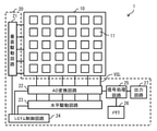
- FIG. 1 shows an example of a schematic configuration of a solid-state image sensor 1 according to an embodiment of the present disclosure.
- the solid-state image sensor 1 is, for example, a camera module including a CMOS (Complementary Metal Oxide Semiconductor) image sensor and a signal processing circuit that processes a signal obtained from the CMOS image sensor.
- the solid-state image sensor 1 includes a pixel array unit 10 provided with a plurality of sensor pixels 11. In the pixel array unit 10, the plurality of sensor pixels 11 are arranged two-dimensionally (in a matrix).
- the sensor pixel 11 is configured to include, for example, a photoelectric conversion element and a pixel circuit.
- the photoelectric conversion element is an element that performs photoelectric conversion to generate an electric charge according to the amount of received light, and is, for example, a photodiode.
- the pixel circuit outputs, for example, a pixel signal based on the electric charge output from the photoelectric conversion element via wiring.
- the pixel array unit 10 generates a plurality of image data at predetermined intervals by imaging.
- the pixel array unit 10 corresponds to a specific example of the "imaging unit" of the present disclosure.
- the pixel array unit 10 has a plurality of sensor pixels 11, a plurality of drive wirings, and a plurality of data output lines VSL.
- the drive wiring is wiring to which a control signal for controlling the output of the electric charge stored in the sensor pixel 11 is applied, and extends in the row direction, for example.
- the plurality of drive wirings are connected to, for example, the output end of the vertical drive circuit 21.
- the data output line VSL is a wiring that outputs a pixel signal (that is, image data) output from each sensor pixel 11 to the peripheral circuit 20, and extends in the column direction, for example.
- the data output line VSL is connected to, for example, the output end of the pixel circuit.
- the solid-state image sensor 1 further includes a peripheral circuit 20 for processing image data.
- the peripheral circuit 20 generates HDR image data based on the image data input from the pixel array unit 10 (hereinafter referred to as “normal image data”) and outputs the HDR image data to the outside.
- the peripheral circuit 20 includes, for example, a vertical drive circuit 21, an AD conversion circuit 22, a horizontal drive circuit 23, a system control circuit 24, a signal processing circuit 25, a memory 26, and an output circuit 27.
- the vertical drive circuit 21 selects, for example, a plurality of sensor pixels 11 in order for each predetermined unit pixel row.
- the “predetermined unit pixel row” refers to a pixel row in which pixels can be selected at the same address.
- the AD conversion circuit 22 performs, for example, Correlated Double Sampling (CDS) processing on the pixel signals output from each sensor pixel 11 in the row selected by the vertical drive circuit 21.
- the AD conversion circuit 22 extracts the signal level of the pixel signal by performing CDS processing, for example, and holds pixel data corresponding to the amount of light received by each sensor pixel 11.
- the AD conversion circuit 22 has, for example, a column signal processing unit for each data output line VSL.
- the column signal processing unit includes, for example, a single slope A / D converter.
- the single slope A / D converter is configured to include, for example, a comparator and a counter circuit.
- the horizontal drive circuit 23 sequentially outputs the pixel data held in the AD conversion circuit 22 to the outside.
- the system control circuit 24 controls, for example, the drive of each block (vertical drive circuit 21, column signal processing circuit 22 and horizontal drive circuit 23) in the peripheral circuit 20.
- the signal processing circuit 25 generates HDR image data based on a plurality of normal image data input from the AD conversion circuit 22.
- the normal image data is image data having a predetermined sensitivity.
- the plurality of ordinary image data input from the AD conversion circuit 22 at predetermined intervals may include a plurality of image data di (1 ⁇ i ⁇ n) having different sensitivities from each other.
- the plurality of ordinary image data input from the AD conversion circuit 22 at predetermined intervals may include, for example, five image data di (1 ⁇ i ⁇ 5) having different sensitivities.
- the difference in sensitivity depends on, for example, the difference in charge accumulation time in the photoelectric conversion element.
- the image data d5 is image data obtained with the longest charge accumulation time among the five image data di.
- the image data d4 is image data obtained with the second longest charge accumulation time among the five image data di.
- the image data d3 is image data obtained with the third longest charge accumulation time among the five image data di.
- the image data d2 is image data obtained with the fourth longest charge accumulation time among the five image data di.
- the image data d1 is image data obtained with the shortest charge accumulation time among the five image data di.
- HDR image data is image data in which the ratio of the minimum brightness and the maximum brightness that can be expressed is larger than that of normal image data. That is, HDR image data is image data having a wider dynamic range than normal image data.
- Dynamic range is the ratio of the minimum and maximum values of an identifiable signal.
- the dynamic range is the ratio of the minimum and maximum brightness that can be expressed.
- the minimum value of the identifiable signal is the luminance level corresponding to the noise level of the solid-state image sensor 1.
- the maximum value of the identifiable signal is the luminance level corresponding to the saturated charge amount of the photoelectric conversion element provided in the solid-state image sensor 1.
- HDR image data is generated by synthesizing at least two image data out of a plurality of image data di obtained at predetermined intervals.
- HDR image data is generated, for example, by synthesizing at least two image data out of five image data di (1 ⁇ i ⁇ 5) obtained at predetermined intervals.
- FIG. 2 shows an example of a functional block of the signal processing circuit 25.
- the signal processing circuit 25 includes, for example, a signal transfer unit 251, a saturation analysis unit 252, and a synthesis unit 253.
- the signal transfer unit 251 stores a plurality of image data di (1 ⁇ i ⁇ n) sequentially input from the AD conversion circuit 22 in time series in the memory 26.
- the signal transfer unit 251 further outputs a plurality of image data di (2 ⁇ i ⁇ n) to the saturation analysis unit 252.
- the saturation analysis unit 252 analyzes the saturation degree ⁇ i (2 ⁇ i ⁇ n) of the image data di each time the image data di (2 ⁇ i ⁇ n) is input from the signal transfer unit 251.
- the saturation analysis unit 252 derives the saturation ⁇ i for each pixel included in the image data di, for example. For example, the saturation analysis unit 252 gives 1 as the saturation ⁇ i to a pixel having a gradation (signal level) exceeding a predetermined threshold value TH_H in the image data di. For example, the saturation analysis unit 252 gives 0 as the saturation ⁇ i to a pixel having a gradation (signal level) below a predetermined threshold value TH_L in the image data di.
- the saturation analysis unit 252 sets the saturation degree ⁇ i to 0 to 1 for a pixel having a gradation (signal level) within a range of a predetermined threshold value TH_L or more and a predetermined threshold value TH_H or less in the image data di. A value between them and proportional to the magnitude of the gradation (signal level) is given.
- the saturation analysis unit 252 stores the derived saturation ⁇ i in the memory 26 in association with the image data di.
- the synthesizing unit 253 reads a plurality of image data di (1 ⁇ i ⁇ n) stored in the memory 26 from the memory 26 at predetermined cycles, and at the same time, a plurality of saturation degrees ⁇ i (2 ⁇ n) stored in the memory 26. i ⁇ n) is read. That is, the compositing unit 253 acquires a plurality of image data di (1 ⁇ i ⁇ n) acquired from the pixel array unit 10 at predetermined cycles by imaging, and also obtains a plurality of image data di (1 ⁇ i ⁇ n). Acquire a plurality of saturation degrees ⁇ i (2 ⁇ i ⁇ n) corresponding to. The compositing unit 253 generates an HDR image based on the acquired plurality of image data di (1 ⁇ i ⁇ n) and a plurality of saturation degrees ⁇ i (2 ⁇ i ⁇ n).
- the compositing unit 253 selects at least two image data as compositing target image data from a plurality of image data di (1 ⁇ i ⁇ n) at predetermined intervals.
- the compositing unit 253 uses the selected compositing target image data as a plurality of saturation degrees corresponding to the plurality of compositing target image data among the plurality of saturation degrees ⁇ i (2 ⁇ i ⁇ n) to create an HDR image.
- the synthesis unit 253 corresponds to a specific example of the "selection unit" and "generation unit" of the present disclosure.
- the synthesizing unit 253 reads, for example, five image data di (1 ⁇ i ⁇ 5) and four saturation degrees ⁇ i (2 ⁇ i ⁇ 5) from the memory 26 at predetermined cycles.
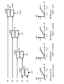
- the synthesis unit 253 has, for example, four synthesis units 253A, 253B, 253C, and 253D, as shown in FIG.
- the compositing unit 253A generates the composite image data D2 by using the image data d1 and d2, the saturation degree ⁇ 2 and the gain G2, for example, as shown in the following formula (1).
- the gain G2 is, for example, a linear relationship between the brightness and the signal level in the composite image data D2 obtained by synthesis when the gain G2 is applied to the signal data of the image data d2 as shown in FIG. It is a value that becomes.
- D2 d1 x ⁇ 2 x G1 + d2 x (1- ⁇ 2) x G2 ... (1)
- the synthesis unit 253B generates the composite image data D3 by using, for example, the composite image data D2, the image data d3, the saturation degree ⁇ 3, and the gain G3, as shown in the following equation (2).
- the gain G3 is, for example, a linear relationship between the brightness and the signal level in the composite image data D3 obtained by synthesis when the gain G3 is applied to the signal data of the image data d3. It is a value that becomes.
- D3 D2 x ⁇ 3 + d3 x (1- ⁇ 3) x G3 ... (2)
- the synthesis unit 253C generates the composite image data D4 by using the composite image data D3, the image data d4, the saturation degree ⁇ 4, and the gain G4, for example, as shown in the following equation (3).
- the gain G4 is, for example, a linear relationship between the brightness and the signal level in the composite image data D4 obtained by synthesis when the gain G4 is applied to the signal data of the image data d4. It is a value that becomes.
- D4 D3 x ⁇ 4 + d4 x (1- ⁇ 4) x G4 ... (3)
- the synthesis unit 253D generates the composite image data D5 by using, for example, the composite image data D4, the image data d5, the saturation degree ⁇ 5, and the gain G5, as shown in the following equation (4).
- the gain G5 is, for example, linear in the composite image data D5 obtained by synthesis when the signal data of the image data d5 is multiplied by the gain G5, as shown in FIG. 4 in the relationship between the brightness and the signal level. It is a value that becomes.
- D5 D4 x ⁇ 5 + d5 x (1- ⁇ 5) ... (4)
- the compositing unit 253 outputs, for example, the compositing image data D5 generated by using the compositing units 253A to 253D to the output circuit 27 as an HDR image.
- the synthesis unit 253 has various HDR modes as shown in FIG. 5, for example.
- a DR (dynamic range) priority mode for synthesizing five image data dis (5-image composite DR priority mode) and a DR priority mode for synthesizing four image data dis (four-image composite DR priority mode).
- SNR priority mode for synthesizing four image data dis (four-image composite SNR priority mode)
- DR priority mode for synthesizing three image data dis (three-image composite DR priority mode)
- three image data dis three image data dis.
- An SNR priority mode for synthesizing (three-sheet synthetic SNR priority mode) is exemplified.
- the compositing unit 253 uses, for example, five image data d1 to d5 as image data to be synthesized in the five-sheet compositing DR priority mode.
- the composition unit 253 uses the four image data d1, d2, d4, and d5 as the image data to be synthesized.
- the composition unit 253 uses the four image data d1, d2, d3, and d4 as the image data to be synthesized.
- the composition unit 253 uses the three image data d1, d4, and d5 as the image data to be synthesized.
- the composition unit 253 uses the three image data d1, d2, and d4 as the image data to be combined.
- the image data d1 not included in the four image data d2, d3, d4, and d5, which are the synthesis targets in the four-sheet composite SNR priority mode is the synthesis target.
- the image data d3 not included in the four image data d1, d2, d4, and d5, which are the synthesis targets in the four-sheet composite DR priority mode is the synthesis target.
- the image data d5 that is not included in the three image data d1, d2, and d4 that are the synthesis targets in the three-sheet composite SNR priority mode is the synthesis target.
- the image data d2 that is not included in the three image data d1, d4, d5 that are the synthesis targets in the three-sheet composite DR priority mode is the synthesis target.
- the compositing unit 253 can also transition from one HDR mode to another HDR mode, for example.
- the compositing unit 253 can, for example, transition from the four-sheet composite DR priority mode to the four-sheet composite SNR priority mode.
- the transition method when transitioning from the 4-sheet composite DR priority mode to the 4-sheet composite SNR priority mode will be described below. First, the mode before the transition will be described, then the mode transition will be described, and finally, the mode after the transition will be described.
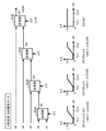
- the compositing unit 253 uses the four selected image data d1, d2, d4, d5 with saturation degrees ⁇ 2, ⁇ 3, ⁇ 4, ⁇ 5 corresponding to the four compositing units 253A, 253B, 253C, and 253D on the low sensitivity side. Synthesize in order from. The compositing unit 253 generates HDR image data in this way.
- the synthesis unit 253B sets the saturation degree ⁇ 3 to 1.0 for all gradations (signal levels) included in the image data d3.
- the compositing unit 253B outputs the composite image data D2 input from the compositing unit 253A to the compositing unit 253C as it is. That is, even if the image data d3 is input to the compositing unit 253B, the compositing unit 253B outputs the composite image data D2 to the compositing unit 253C.
- the same processing as described with reference to FIG. 3 is performed.
- the compositing unit 253 is among the five image data di (1 ⁇ i ⁇ 5) obtained in a predetermined cycle by imaging when the transition from the four-sheet composite DR priority mode to the four-sheet composite SNR priority mode is set. Therefore, four image data d1, d2, d3, and d4 suitable for the four-sheet synthesis SNR priority mode are selected as the synthesis target. That is, the compositing unit 253 includes four images suitable for the four-sheet compositing SNR priority mode, including the image data d3 that does not correspond to the four-sheet compositing DR priority mode, out of the five image data di (1 ⁇ i ⁇ 5). Data d1, d2, d3, d4 are selected as synthesis targets. The four image data d1, d2, d4, and d5 suitable for the four-sheet composite DR priority mode include image data d5 that does not correspond to the four-sheet composite SNR priority mode.
- the compositing unit 253 has a saturation degree ⁇ 3 corresponding to the image data d3 not corresponding to the four-sheet composite DR priority mode and a saturation degree ⁇ 5 corresponding to the image data d5 not corresponding to the four-sheet composite SNR priority mode. Is changed over time to replace the four image data d1, d2, d4, d5 with the four image data d1, d2, d3, d4.
- the compositing unit 253 changes the saturation degree ⁇ 5 corresponding to the image data d5 that does not correspond to the four-sheet compositing SNR priority mode over time in the stage before the mode transition from the four-sheet compositing DR priority mode to the four-sheet compositing SNR priority mode.
- Image data d5 is excluded from the synthesis target.
- the synthesis unit 253 changes the saturation degree ⁇ 3 corresponding to the image data d3 that does not correspond to the 4-sheet synthesis DR priority mode over time in the subsequent stage of the mode transition from the 4-sheet synthesis DR priority mode to the 4-sheet synthesis SNR priority mode. And include the image data d3 in the composition target.
- the compositing unit 253B keeps the saturation degree ⁇ 3 at 1.0 for all gradations (signal levels) included in the image data d3.
- the compositing unit 253B continues to output the composite image data D2 input from the compositing unit 253A to the compositing unit 253C as it is.
- the compositing unit 253D has a value equal to or less than the threshold value TH_H at the saturation degree ⁇ 5 until the saturation degree ⁇ 5 becomes 1.0 at all gradations (signal levels) included in the image data d3. Gradually increase over time.
- the compositing unit 253D gradually reduces the compositing ratio of the image data d5 to the composite image data D4 over time.
- the values within the range of the threshold value TH_L or more and the threshold value TH_H or less at the saturation degree ⁇ 5 are, for example, the slope of the line segment connecting the value at the threshold value TH_L and the value at the threshold value TH_H at the saturation degree ⁇ 5 over time. It may be changed so as to gradually become smaller.
- the values within the range of the threshold value TH_L or more and the threshold value TH_H or less at the saturation degree ⁇ 5 are, for example, the value at the threshold value TH_L and the threshold value TH_H at the saturation degree ⁇ 5 after setting the upper limit value to 1 and the lower limit value to 0.
- the inclination of the line segment connecting the hour value may remain constant, and the offset given to the line segment may be changed so as to gradually increase with time.
- the compositing unit 253D sets the compositing ratio of the image data d5 to the composite image data D4 to zero when the saturation degree ⁇ 5 becomes 1.0. That is, when the saturation degree ⁇ 5 becomes 1.0, the image data d5 is not used for image composition.
- the same processing as that described with reference to FIG. 3 is performed.
- the synthesizing unit 253D keeps the saturation degree ⁇ 5 at 1.0 for all gradations (signal levels) included in the image data d3, for example, as shown in FIG. As a result, the compositing unit 253D continues to output the composite image data D4 input from the compositing unit 253C to the output circuit 27 as it is.
- the synthesizing unit 253B for example, as shown in FIG. 8, the saturation degree ⁇ 3 corresponding to the pixel having the gradation (signal data) less than the threshold value TH_L in the image data d3 becomes 0, and the threshold value TH_L or more in the image data d3.
- the saturation ⁇ 3 corresponding to a pixel having a gradation (signal level) within the range of the threshold value TH_H is a value between 0 and 1, and is a value proportional to the magnitude of the gradation (signal level).
- the value below the threshold value TH_H at the saturation degree ⁇ 3 is gradually reduced over time. That is, the compositing unit 253B gradually increases the compositing ratio of the image data d3 to the composite image data D2 over time.
- the values within the range of the threshold value TH_L or more and the threshold value TH_H or less at the saturation degree ⁇ 3 are, for example, the slope of the line segment connecting the value at the threshold value TH_L and the value at the threshold value TH_H at the saturation degree ⁇ 3 over time. It may be changed so as to gradually increase. Further, the values within the range of the threshold value TH_L or more and the threshold value TH_H or less at the saturation degree ⁇ 3 are, for example, the value at the threshold value TH_L and the threshold value TH_H at the saturation degree ⁇ 3 after setting the upper limit value to 1 and the lower limit value to 0.
- the inclination of the line segment connecting the hour value may remain constant, and the offset given to the line segment may be changed so as to gradually decrease with time.
- the synthesis unit 253B stops the change of the saturation degree ⁇ 3 when the saturation degree ⁇ 3 reaches the above condition. That is, when the saturation degree ⁇ 3 reaches the above condition, the saturation degree ⁇ 3 becomes constant.
- the same processing as described with reference to FIG. 3 is performed.
- the synthesis unit 253D sets the saturation degree ⁇ 5 to 1.0 for all gradations (signal levels) included in the image data d5.
- the compositing unit 253D outputs the composite image data D4 input from the compositing unit 253C to the output circuit 27 as it is. That is, even if the image data d5 is input to the compositing unit 253D, the compositing unit 253D outputs the composite image data D4 to the output circuit 27.
- the synthesizing units 253A, 253B, and 253C the same processing as described with reference to FIG. 3 is performed.
- Patent Documents 1 and 2 disclose HDR technology for synthesizing a plurality of images having different sensitivities to generate one image having a wide dynamic range.
- HDR technology there is a trade-off between expanding the dynamic range and reducing the SNR.
- the number of combined sheets is increased, there is a problem that the amount of data to be processed increases and the power consumption increases.
- At least two image data di selected from a plurality of image data di (1 ⁇ i ⁇ n) having different sensitivities are combined to be more dynamic than the image data di.
- HDR image data with a wide range is generated. This makes it possible to suppress an increase in the amount of data to be processed, for example, by selecting the number of composites and the type of image according to the purpose. As a result, power consumption can be suppressed.
- the circuit scale of the circuit for synthesis (synthesis unit 253) is larger than that when the maximum number of composites is set to n. The increase can be suppressed.
- At least two image data dis are combined in order from the low sensitivity side. This makes it possible to select the number of composites and the type of image according to the purpose, for example, by setting the saturation degree ⁇ i corresponding to the image data di. Further, for example, when performing the mode transition as described above, it is possible to select the number of composites and the type of image according to the purpose only by changing the saturation degree ⁇ i with time.
- the saturation degree ⁇ i of the image data di on the high sensitivity side is calculated, and the calculated saturation degree ⁇ i is used.
- Image composition is performed.
- At least two image data dis which are a part of the plurality of image data dis (1 ⁇ i ⁇ n) acquired from the pixel array unit 10 by imaging at predetermined cycles, are present. Selected as a synthesis target. This makes it possible to select, for example, the number of composites and the type of image according to the purpose.
- the saturation degree ⁇ i is changed over time to be synthesized. Is replaced with a plurality of image data di suitable for the first HDR mode with a plurality of image data di suitable for the second HDR mode.
- the saturation degree ⁇ i is changed over time, the appearance of the image during the mode transition can be gradually changed to the extent that the user cannot visually recognize the change in the image.
- the solid-state image sensor 1 according to the present embodiment can be suitably used for, for example, an application in which a mode transition occurs during moving image shooting (for example, a drive recorder or the like).
- the second HDR mode when transitioning from the first HDR mode to the second HDR mode, it is suitable for the second HDR mode included in the plurality of image data di suitable for the first HDR mode.
- Image data suitable for the first HDR mode which is included in a plurality of image data di suitable for the second HDR mode after the saturation ⁇ i corresponding to the image data di that does not correspond to the image data di changes with time.
- the saturation degree ⁇ i corresponding to the image data di that does not correspond to di over time the synthesis target is from a plurality of image data di suitable for the first HDR mode to a plurality of image data di suitable for the second HDR mode. It is replaced with image data di.
- the solid-state image sensor 1 according to the present embodiment can be suitably used for, for example, an application in which a mode transition occurs during moving image shooting (for example, a drive recorder or the like).
- the combined number is 3 to 5 is exemplified, but the combined number may be 2 or 6 or more.
- the two image data are combined by setting the blend ratio of the two image data using the saturation degree ⁇ i, but the two images are combined by using another method. Data may be combined.
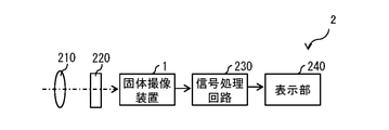
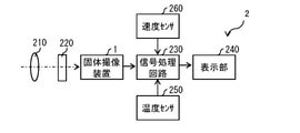
- FIG. 10 shows an example of a schematic configuration of an image pickup system 2 provided with the solid-state image pickup device 1 according to the above embodiment.
- the image pickup system 2 corresponds to a specific example of the "electronic device" of the present disclosure.
- the image pickup system 2 includes, for example, an optical system 210, a shutter mechanism 220, a solid-state image pickup device 1, a signal processing circuit 230, and a display unit 240.
- the optical system 210 forms an image of image light (incident light) from the subject on the image pickup surface of the solid-state image pickup device 1. As a result, the signal charge is accumulated in the solid-state image sensor 1 for a certain period of time.
- the shutter mechanism 220 controls the light irradiation period and the light shielding period to the solid-state image sensor 1 by opening and closing.
- the solid-state imaging device 1 receives image light (incident light) incident from the optical system 210, and outputs image data (HDR image data) corresponding to the received image light (incident light) to the signal processing circuit 230.
- the signal processing circuit 230 processes the image data (HDR image data) input from the solid-state imaging device 1 to generate video data (HDR video data).
- the signal processing circuit 230 further generates a video signal corresponding to the generated video data (HDR video data) and outputs the video signal to the display unit 240.
- the display unit 240 displays a video (HDR video) based on a video signal (HDR video data) input from the signal processing circuit 230.
- the image pickup system 2 may include, for example, a temperature sensor 250 as shown in FIG.
- the temperature sensor 250 measures, for example, the outside air temperature, and outputs the data (temperature data) obtained by the measurement to the signal processing circuit 230.
- the signal processing circuit 230 outputs the temperature data input from the temperature sensor 250 to the solid-state imaging device 1 (signal processing circuit 25).
- the signal processing circuit 25 selects one HDR mode from a plurality of selectable HDR modes using the input temperature data.
- the signal processing circuit 25 shifts to an appropriate HDR mode according to the change. In this case, appropriate HDR image data according to the temperature can be used.
- the imaging system 2 may include, for example, a speed sensor 260 as shown in FIG.
- the speed sensor 260 measures, for example, the speed of a moving body on which the image pickup system 2 is mounted, and outputs the data (speed data) obtained thereby to the signal processing circuit 230.
- the signal processing circuit 230 outputs the speed data input from the speed sensor 260 to the solid-state imaging device 1 (signal processing circuit 25).
- the signal processing circuit 25 selects one HDR mode from a plurality of selectable HDR modes using the input speed data.
- the signal processing circuit 25 shifts to an appropriate HDR mode according to the change. In this case, appropriate HDR image data according to the speed can be used.
- FIG. 13 shows an example of a schematic configuration of a mobile body 3 provided with an image pickup system 2 (for example, the image pickup system 2 shown in FIG. 10) according to the above application example.
- the moving body 3 includes, for example, an image pickup system 2, an ECU (Electronic Control Unit) 4, a temperature sensor 5, and a speed sensor 6.
- the ECU 4 is a device that controls various functions provided in the mobile body 3, such as a transmission and a lane keeping system.
- the temperature sensor 5 measures, for example, the outside air temperature of the moving body 3 and outputs the data (temperature data) obtained by the measurement to the ECU 4.
- the ECU 4 outputs the temperature data input from the temperature sensor 5 to the solid-state image sensor 1 (signal processing circuit 25).
- the signal processing circuit 25 selects one HDR mode from a plurality of selectable HDR modes using the input speed data.
- the signal processing circuit 25 shifts to an appropriate HDR mode according to the change. In this case, the ECU 4 can use appropriate HDR image data according to the speed.
- the speed sensor 6 measures, for example, the speed of the moving body 3 on which the image pickup system 2 is mounted, and outputs the data (speed data) obtained by the measurement to the ECU 4.
- the ECU 4 outputs the speed data input from the speed sensor to the solid-state image sensor 1 (signal processing circuit 25).
- the signal processing circuit 25 selects one HDR mode from a plurality of selectable HDR modes using the input speed data.
- the signal processing circuit 25 shifts to an appropriate HDR mode according to the change. In this case, the ECU 4 can use appropriate HDR image data according to the speed.
- the present disclosure may have the following structure.
- a selection unit that selects at least two image data as image data to be combined from a plurality of image data having different sensitivities.
- a solid body including a generation unit that generates HDR (High Dynamic Range) image data having a wider dynamic range than the image data by synthesizing at least two images to be combined, which are selected by the selection unit.
- Imaging device The solid-state image sensor according to (1), wherein the generation unit synthesizes at least two images to be combined in order from the low sensitivity side.
- the generation unit calculates the saturation degree of the composite target image data on the high-sensitivity side of the two composite target image data included in at least two composite target image data, and calculates the saturation degree.
- the solid-state imaging device wherein the two images to be combined included in at least two image data to be combined are combined by using the image.
- an imaging unit that generates the plurality of image data at predetermined intervals by imaging is further provided.
- the selection unit selects at least two image data, which are a part of the plurality of image data acquired from the image pickup unit at each predetermined cycle, as the image data to be synthesized (1) to.
- the solid-state imaging device according to any one of (3).
- the selection unit selects at least two image data suitable for the first mode from the plurality of image data as the first image data to be combined.
- the selection unit is one or a plurality of image data that do not correspond to the first image data to be synthesized from the plurality of image data. At least two image data suitable for the second mode, including the above, are selected as the second image data to be combined.
- the generation unit changes the saturation degree over time when transitioning from the first mode to the second mode, so that the synthesis target image data is obtained from the first synthesis target image data.
- the solid-state image sensor according to (3) which is replaced with the second image data to be synthesized. (6)
- the generation unit transitions from the first mode to the second mode, the third mode is included in the plurality of first synthesis target image data and does not correspond to the second synthesis target image data.
- a fourth composition target image that is included in the plurality of second composition target image data and does not correspond to the first composition target image data.
- a selection unit that selects at least two image data as image data to be combined from a plurality of image data having different sensitivities.
- HDR High Dynamic Range
- image data is obtained by synthesizing at least two image data to be combined selected from a plurality of image data having different sensitivities. Since HDR image data having a wider dynamic range is generated, for example, an increase in the amount of data to be processed can be suppressed by selecting the number of composites and the type of image according to the purpose. As a result, it is possible to suppress an increase in power consumption.
Landscapes
- Engineering & Computer Science (AREA)
- Multimedia (AREA)
- Signal Processing (AREA)
- Physics & Mathematics (AREA)
- General Physics & Mathematics (AREA)
- Studio Devices (AREA)
- Transforming Light Signals Into Electric Signals (AREA)
Abstract
固体撮像装置は、感度の互いに異なる複数の画像データの中から、少なくとも2枚の画像データを合成対象画像データとして選択する選択部と、選択部で選択された、少なくとも2枚の合成対象画像データを合成することにより、画像データよりもダイナミックレンジの広いHDR画像データを生成する生成部とを備えた。
Description
本開示は、固体撮像装置および電子機器に関する。
感度の互いに異なる複数枚の画像を合成し、ダイナミックレンジの広い1枚の画像を生成するHDR(High Dynamic Range)技術が、例えば、特許文献1,2に開示されている。HDR技術では、ダイナミックレンジの拡大と、SNR(Signal-to-Noise Ratio)の低減とがトレードオフの関係にある。
ところで、HDR技術では、合成枚数を増やすことで、ダイナミックレンジの拡大と、SNRの低減とを同時に満たすことが可能である。しかし、合成枚数を増やすと、処理するデータ量が増え、消費電力が増大するという問題があった。従って、消費電力の増大を抑えることの可能な固体撮像装置およびそれを備えた電子機器を提供することが望ましい。
本開示の一実施の形態に係る固体撮像装置は、感度の互いに異なる複数の画像データの中から、少なくとも2枚の画像データを合成対象画像データとして選択する選択部と、選択部で選択された、少なくとも2枚の合成対象画像データを合成することにより、画像データよりもダイナミックレンジの広いHDR画像データを生成する生成部とを備えている。
本開示の一実施の形態に係る電子機器は、感度の互いに異なる複数の画像データの中から、少なくとも2枚の画像データを合成対象画像データとして選択する選択部と、前記選択部で選択された、少なくとも2枚の前記合成対象画像データを合成することにより、前記画像データよりもダイナミックレンジの広いHDR画像データを生成する生成部とを備えている。
本開示の一実施の形態に係る固体撮像装置および電子機器では、感度の互いに異なる複数の画像データの中から選択された、少なくとも2枚の合成対象画像データを合成することにより、画像データよりもダイナミックレンジの広いHDR画像データが生成される。これにより、例えば、目的に応じた合成枚数や画像の種類を選択することにより、処理するデータ量の増大が抑えられる。
以下、本開示の実施の形態について、図面を参照して詳細に説明する。なお、説明は以下の順序で行う。
1.実施の形態(固体撮像装置)…図1~図9
HDR画像を生成する回路をカメラモジュール内に備えた例
2.変形例(固体撮像装置)
3.適用例(撮像システム)…図10~図12
4.応用例(移動体)…図13
1.実施の形態(固体撮像装置)…図1~図9
HDR画像を生成する回路をカメラモジュール内に備えた例
2.変形例(固体撮像装置)
3.適用例(撮像システム)…図10~図12
4.応用例(移動体)…図13
<1.実施の形態>
[構成]
図1は、本開示の一実施の形態に係る固体撮像装置1の概略構成の一例を表す。固体撮像装置1は、例えば、CMOS(Complementary Metal Oxide Semiconductor)イメージセンサと、CMOSイメージセンサから得られた信号を処理する信号処理回路とを備えたカメラモジュールである。固体撮像装置1は、複数のセンサ画素11が設けられた画素アレイ部10を備えている。画素アレイ部10において、複数のセンサ画素11は、2次元(行列状に)配置されている。
[構成]
図1は、本開示の一実施の形態に係る固体撮像装置1の概略構成の一例を表す。固体撮像装置1は、例えば、CMOS(Complementary Metal Oxide Semiconductor)イメージセンサと、CMOSイメージセンサから得られた信号を処理する信号処理回路とを備えたカメラモジュールである。固体撮像装置1は、複数のセンサ画素11が設けられた画素アレイ部10を備えている。画素アレイ部10において、複数のセンサ画素11は、2次元(行列状に)配置されている。
センサ画素11は、例えば、光電変換素子および画素回路を含んで構成されている。光電変換素子は、光電変換を行って受光量に応じた電荷を発生する素子であり、例えば、フォトダイオードである。画素回路は、たとえば、配線を介して、光電変換素子から出力された電荷に基づく画素信号を出力する。
画素アレイ部10は、撮像により所定の周期ごとに複数の画像データを生成する。画素アレイ部10は、本開示の「撮像部」の一具体例に相当する。画素アレイ部10は、複数のセンサ画素11と、複数の駆動配線と、複数のデータ出力線VSLとを有している。駆動配線は、センサ画素11に蓄積された電荷の出力を制御する制御信号が印加される配線であり、例えば、行方向に延在している。複数の駆動配線は、例えば、垂直駆動回路21の出力端に接続されている。データ出力線VSLは、各センサ画素11から出力された画素信号(つまり、画像データ)を周辺回路20に出力する配線であり、例えば、列方向に延在している。データ出力線VSLは、例えば、画素回路の出力端に接続されている。
固体撮像装置1は、さらに、画像データを処理する周辺回路20を備えている。周辺回路20は、画素アレイ部10から入力された画像データ(以下、「通常の画像データ」と称する)に基づいてHDR画像データを生成し、外部に出力する。周辺回路20は、例えば、垂直駆動回路21、AD変換回路22、水平駆動回路23、システム制御回路24、信号処理回路25、メモリ26および出力回路27を有している。
垂直駆動回路21は、例えば、複数のセンサ画素11を所定の単位画素行ごとに順に選択する。「所定の単位画素行」とは、同一アドレスで画素選択可能な画素行を指している。AD変換回路22は、例えば、垂直駆動回路21によって選択された行の各センサ画素11から出力される画素信号に対して、相関二重サンプリング(Correlated Double Sampling:CDS)処理を施す。AD変換回路22は、例えば、CDS処理を施すことにより、画素信号の信号レベルを抽出し、各センサ画素11の受光量に応じた画素データを保持する。AD変換回路22は、例えば、データ出力線VSLごとにカラム信号処理部を有している。カラム信号処理部は、例えば、シングルスロープA/D変換器を含んでいる。シングルスロープA/D変換器は、例えば、比較器およびカウンタ回路を含んで構成されている。水平駆動回路23は、例えば、AD変換回路22に保持されている画素データを順次、外部に出力する。システム制御回路24は、例えば、周辺回路20内の各ブロック(垂直駆動回路21、カラム信号処理回路22および水平駆動回路23)の駆動を制御する。
信号処理回路25は、AD変換回路22から入力された複数の通常の画像データに基づいて、HDR画像データを生成する。ここで、通常の画像データは、所定の感度の画像データである。所定の周期ごとに、AD変換回路22から入力される複数の通常の画像データには、感度の互いに異なる複数の画像データdi(1≦i≦n)が含まれ得る。所定の周期ごとに、AD変換回路22から入力される複数の通常の画像データには、例えば、感度の互いに異なる5枚の画像データdi(1≦i≦5)が含まれ得る。感度の違いは、例えば、光電変換素子における電荷蓄積時間の違いに依る。
ここで、上述の5枚の画像データdi(1≦i≦5)に着目する。画像データd5は、5枚の画像データdiの中で最も長い電荷蓄積時間で得られた画像データである。画像データd4は、5枚の画像データdiの中で2番目に長い電荷蓄積時間で得られた画像データである。画像データd3は、5枚の画像データdiの中で3番目に長い電荷蓄積時間で得られた画像データである。画像データd2は、5枚の画像データdiの中で4番目に長い電荷蓄積時間で得られた画像データである。画像データd1は、5枚の画像データdiの中で最も短い電荷蓄積時間で得られた画像データである。
HDR画像データは、通常の画像データよりも表現し得る最小輝度と最大輝度の比率が大きい画像データのことである。つまり、HDR画像データは、通常の画像データよりもダイナミックレンジの広い画像データのことである。ダイナミックレンジとは、識別可能な信号の最小値と最大値との比率のことである。換言すれば、ダイナミックレンジとは、表現しうる最小輝度と最大輝度との比率のことである。例えば、識別可能な信号の最小値は、固体撮像装置1のノイズレベルに対応する輝度レベルである。一方、識別可能な信号の最大値は、固体撮像装置1に設けられた光電変換素子の飽和電荷量に対応する輝度レベルである。
HDR画像データは、所定の周期ごとに得られる複数の画像データdiのうち少なくとも2枚の画像データを合成することにより生成される。HDR画像データは、例えば、所定の周期ごとに得られる5枚の画像データdi(1≦i≦5)のうち少なくとも2枚の画像データを合成することにより生成される。
次に、HDR画像データのより具体的な生成方法について説明する。図2は、信号処理回路25の機能ブロックの一例を表したものである。信号処理回路25は、例えば、信号転送部251、飽和度解析部252および合成部253を有している。
信号転送部251は、AD変換回路22から時系列に順次入力された複数の画像データdi(1≦i≦n)をメモリ26に格納する。信号転送部251は、さらに、複数の画像データdi(2≦i≦n)を飽和度解析部252に出力する。
飽和度解析部252は、信号転送部251から画像データdi(2≦i≦n)が入力されるたびに、画像データdiの飽和度αi(2≦i≦n)を解析する。飽和度解析部252は、例えば、画像データdiに含まれる画素ごとに、飽和度αiを導出する。飽和度解析部252は、例えば、画像データdiにおいて所定の閾値TH_Hを超える階調(信号レベル)を有する画素に対して、飽和度αiとして1を与える。飽和度解析部252は、例えば、画像データdiにおいて所定の閾値TH_Lを下回る階調(信号レベル)を有する画素に対して、飽和度αiとして0を与える。飽和度解析部252は、例えば、画像データdiにおいて所定の閾値TH_L以上、所定の閾値TH_H以下の範囲内の階調(信号レベル)を有する画素に対して、飽和度αiとして、0~1の間の値であって、かつ階調(信号レベル)の大きさに比例した値を与える。飽和度解析部252は、導出した飽和度αiを、画像データdiと対応つけてメモリ26に格納する。
合成部253は、所定の周期ごとにメモリ26から、メモリ26に格納された複数の画像データdi(1≦i≦n)を読み出すとともに、メモリ26に格納された複数の飽和度αi(2≦i≦n)を読み出す。つまり、合成部253は、撮像により所定の周期ごとに画素アレイ部10から取得した複数の画像データdi(1≦i≦n)を取得するとともに、複数の画像データdi(1≦i≦n)に対応する複数の飽和度αi(2≦i≦n)を取得する。合成部253は、取得した複数の画像データdi(1≦i≦n)および複数の飽和度αi(2≦i≦n)に基づいて、HDR画像を生成する。
合成部253は、所定の周期ごとに、複数の画像データdi(1≦i≦n)の中から、少なくとも2つの画像データを合成対象画像データとして選択する。合成部253は、選択した複数の合成対象画像データを、複数の飽和度αi(2≦i≦n)のうち、複数の合成対象画像データに対応する複数の飽和度を用いて、HDR画像を生成する。合成部253が、本開示の「選択部」「生成部」の一具体例に相当する。
合成部253は、例えば、所定の周期ごとに、5つの画像データdi(1≦i≦5)と、4つの飽和度αi(2≦i≦5)とをメモリ26から読み出す。合成部253は、例えば、読み出した5つの画像データdi(1≦i≦5)を低感度側から順番に合成する。
次に、低感度側から順番に合成することについて、詳細に説明する。合成部253は、例えば、図3に示したように、4つの合成部253A,253B,253C,253Dを有している。
合成部253Aは、例えば、以下の式(1)に示したように、画像データd1,d2、飽和度α2およびゲインG2を用いて、合成画像データD2を生成する。ゲインG2は、例えば、画像データd2の信号データに対してゲインG2をかけたときに、合成により得られる合成画像データD2において、明るさと信号レベルとの関係が図4に示したような線形となるような値となっている。
D2=d1×α2×G1+d2×(1-α2)×G2…(1)
D2=d1×α2×G1+d2×(1-α2)×G2…(1)
合成部253Bは、例えば、以下の式(2)に示したように、合成画像データD2、画像データd3、飽和度α3およびゲインG3を用いて、合成画像データD3を生成する。ゲインG3は、例えば、画像データd3の信号データに対してゲインG3をかけたときに、合成により得られる合成画像データD3において、明るさと信号レベルとの関係が図4に示したような線形となるような値となっている。
D3=D2×α3+d3×(1-α3)×G3…(2)
D3=D2×α3+d3×(1-α3)×G3…(2)
合成部253Cは、例えば、以下の式(3)に示したように、合成画像データD3、画像データd4、飽和度α4およびゲインG4を用いて、合成画像データD4を生成する。ゲインG4は、例えば、画像データd4の信号データに対してゲインG4をかけたときに、合成により得られる合成画像データD4において、明るさと信号レベルとの関係が図4に示したような線形となるような値となっている。
D4=D3×α4+d4×(1-α4)×G4…(3)
D4=D3×α4+d4×(1-α4)×G4…(3)
合成部253Dは、例えば、以下の式(4)に示したように、合成画像データD4、画像データd5、飽和度α5およびゲインG5を用いて、合成画像データD5を生成する。ゲインG5は、例えば、画像データd5の信号データに対してゲインG5をかけたときに、合成により得られる合成画像データD5において、明るさと信号レベルとの関係が図4に示したような線形となるような値となっている。
D5=D4×α5+d5×(1-α5)…(4)
D5=D4×α5+d5×(1-α5)…(4)
合成部253は、例えば、合成部253A~253Dを用いて生成した合成画像データD5をHDR画像として出力回路27に出力する。
合成部253は、例えば、図5に示したような各種HDRモードを有している。図5には、5枚の画像データdiを合成するDR(ダイナミックレンジ)優先モード(5枚合成DR優先モード)、4枚の画像データdiを合成するDR優先モード(4枚合成DR優先モード)、4枚の画像データdiを合成するSNR優先モード(4枚合成SNR優先モード)、3枚の画像データdiを合成するDR優先モード(3枚合成DR優先モード)および3枚の画像データdiを合成するSNR優先モード(3枚合成SNR優先モード)が例示されている。
合成部253は、例えば、5枚合成DR優先モードでは、5枚の画像データd1~d5を合成対象の画像データとする。合成部253は、例えば、4枚合成DR優先モードでは、4枚の画像データd1,d2,d4,d5を合成対象の画像データとする。合成部253は、例えば、4枚合成SNR優先モードでは、4枚の画像データd1,d2,d3,d4を合成対象の画像データとする。合成部253は、例えば、3枚合成DR優先モードでは、3枚の画像データd1,d4,d5を合成対象の画像データとする。合成部253は、例えば、3枚合成SNR優先モードでは、3枚の画像データd1,d2,d4を合成対象の画像データとする。
ここで、4枚合成DR優先モードでは、4枚合成SNR優先モードにおける合成対象である4枚の画像データd2,d3,d4,d5に含まれていない画像データd1が合成対象となっている。一方、4枚合成SNR優先モードでは、4枚合成DR優先モードにおける合成対象である4枚の画像データd1,d2,d4,d5に含まれていない画像データd3が合成対象となっている。
また、3枚合成DR優先モードでは、3枚合成SNR優先モードにおける合成対象である3枚の画像データd1,d2,d4に含まれていない画像データd5が合成対象となっている。一方、3枚合成SNR優先モードでは、3枚合成DR優先モードにおける合成対象である3枚の画像データd1,d4,d5に含まれていない画像データd2が合成対象となっている。
合成部253は、例えば、あるHDRモードから、別のHDRモードに遷移することも可能となっている。合成部253は、例えば、4枚合成DR優先モードから4枚合成SNR優先モードに遷移することが可能となっている。以下に、4枚合成DR優先モードから4枚合成SNR優先モードに遷移するときの遷移方法について説明する。最初に、遷移前のモードについて説明し、その後、モード遷移について説明し、最後に、遷移後のモードについて説明する。
(4枚合成DR優先モード)
このモードでは、例えば、図6に示したように、撮像により所定の周期で得られた5つの画像データdi(1≦i≦5)のうち、4つの画像データd1,d2,d4,d5が画像合成に使用され、画像データd3だけが画像合成に使用されない。つまり、合成部253は、4枚合成DR優先モードが設定されたとき、撮像により所定の周期で得られた5つの画像データdi(1≦i≦5)の中から、4枚合成DR優先モードに適した4つの画像データd1,d2,d4,d5を合成対象として選択する。合成部253は、選択された4つの画像データd1,d2,d4,d5を、4つの合成部253A,253B,253C,253Dに対応する飽和度α2,α3,α4,α5を用いて低感度側から順番に合成する。合成部253は、このようにして、HDR画像データを生成する。
このモードでは、例えば、図6に示したように、撮像により所定の周期で得られた5つの画像データdi(1≦i≦5)のうち、4つの画像データd1,d2,d4,d5が画像合成に使用され、画像データd3だけが画像合成に使用されない。つまり、合成部253は、4枚合成DR優先モードが設定されたとき、撮像により所定の周期で得られた5つの画像データdi(1≦i≦5)の中から、4枚合成DR優先モードに適した4つの画像データd1,d2,d4,d5を合成対象として選択する。合成部253は、選択された4つの画像データd1,d2,d4,d5を、4つの合成部253A,253B,253C,253Dに対応する飽和度α2,α3,α4,α5を用いて低感度側から順番に合成する。合成部253は、このようにして、HDR画像データを生成する。
このとき、合成部253Bは、飽和度α3を、画像データd3に含まれる全ての階調(信号レベル)において1.0とする。これにより、合成部253Bは、合成部253Aから入力された合成画像データD2をそのまま、合成部253Cに出力する。つまり、画像データd3が合成部253Bに入力されていたとしても、合成部253Bは、合成画像データD2を合成部253Cに出力する。合成部253A,253C,253Dについては、図3を用いて説明した処理と同様の処理を行う。
(モード遷移)
合成部253は、4枚合成DR優先モードから4枚合成SNR優先モードへの遷移が設定されたとき、撮像により所定の周期で得られた5つの画像データdi(1≦i≦5)の中から、4枚合成SNR優先モードに適した4つの画像データd1,d2,d3,d4を合成対象として選択する。つまり、合成部253は、5つの画像データdi(1≦i≦5)の中から、4枚合成DR優先モードに該当しない画像データd3を含む、4枚合成SNR優先モードに適した4つの画像データd1,d2,d3,d4を合成対象として選択する。なお、4枚合成DR優先モードに適した4つの画像データd1,d2,d4,d5には、4枚合成SNR優先モードに該当しない画像データd5が含まれている。
合成部253は、4枚合成DR優先モードから4枚合成SNR優先モードへの遷移が設定されたとき、撮像により所定の周期で得られた5つの画像データdi(1≦i≦5)の中から、4枚合成SNR優先モードに適した4つの画像データd1,d2,d3,d4を合成対象として選択する。つまり、合成部253は、5つの画像データdi(1≦i≦5)の中から、4枚合成DR優先モードに該当しない画像データd3を含む、4枚合成SNR優先モードに適した4つの画像データd1,d2,d3,d4を合成対象として選択する。なお、4枚合成DR優先モードに適した4つの画像データd1,d2,d4,d5には、4枚合成SNR優先モードに該当しない画像データd5が含まれている。
合成部253は、この遷移の際に、4枚合成DR優先モードに該当しない画像データd3に対応する飽和度α3と、4枚合成SNR優先モードに該当しない画像データd5に対応する飽和度α5とを経時的に変化させることにより、合成対象を、4つの画像データd1,d2,d4,d5から4つの画像データd1,d2,d3,d4に置き換える。合成部253は、4枚合成DR優先モードから4枚合成SNR優先モードへのモード遷移の前段において、4枚合成SNR優先モードに該当しない画像データd5に対応する飽和度α5を経時的に変化させ、画像データd5を合成対象から除外する。続いて、合成部253は、4枚合成DR優先モードから4枚合成SNR優先モードへのモード遷移の後段において、4枚合成DR優先モードに該当しない画像データd3に対応する飽和度α3を経時的に変化させ、画像データd3を合成対象に含める。
(モード遷移の前段)
まず、合成部253Bは、例えば、図7に示したように、飽和度α3を、画像データd3に含まれる全ての階調(信号レベル)において1.0のままにしておく。これにより、合成部253Bは、合成部253Aから入力された合成画像データD2をそのまま、合成部253Cに出力し続ける。合成部253Dは、例えば、図7に示したように、飽和度α5が画像データd3に含まれる全ての階調(信号レベル)において1.0となるまで、飽和度α5における閾値TH_H以下の値を経時的に徐々に大きくしていく。つまり、合成部253Dは、合成画像データD4に対する画像データd5の合成割合を経時的に徐々に小さくしていく。このとき、飽和度α5における閾値TH_L以上、閾値TH_H以下の範囲内の値は、例えば、飽和度α5における閾値TH_Lのときの値と閾値TH_Hのときの値とを結ぶ線分の傾きが経時的に徐々に小さくなるように変化してもよい。また、飽和度α5における閾値TH_L以上、閾値TH_H以下の範囲内の値は、例えば、上限値を1、下限値を0としたうえで、飽和度α5における閾値TH_Lのときの値と閾値TH_Hのときの値とを結ぶ線分の傾きが一定のままで、その線分に対して与えるオフセットが経時的に徐々に大きくなるように変化してもよい。合成部253Dは、飽和度α5が1.0になった段階で、合成画像データD4に対する画像データd5の合成割合をゼロにする。つまり、飽和度α5が1.0になると、画像データd5が画像合成に使用されなくなる。なお、合成部253A,253Cについては、図3を用いて説明した処理と同様の処理を行う。
まず、合成部253Bは、例えば、図7に示したように、飽和度α3を、画像データd3に含まれる全ての階調(信号レベル)において1.0のままにしておく。これにより、合成部253Bは、合成部253Aから入力された合成画像データD2をそのまま、合成部253Cに出力し続ける。合成部253Dは、例えば、図7に示したように、飽和度α5が画像データd3に含まれる全ての階調(信号レベル)において1.0となるまで、飽和度α5における閾値TH_H以下の値を経時的に徐々に大きくしていく。つまり、合成部253Dは、合成画像データD4に対する画像データd5の合成割合を経時的に徐々に小さくしていく。このとき、飽和度α5における閾値TH_L以上、閾値TH_H以下の範囲内の値は、例えば、飽和度α5における閾値TH_Lのときの値と閾値TH_Hのときの値とを結ぶ線分の傾きが経時的に徐々に小さくなるように変化してもよい。また、飽和度α5における閾値TH_L以上、閾値TH_H以下の範囲内の値は、例えば、上限値を1、下限値を0としたうえで、飽和度α5における閾値TH_Lのときの値と閾値TH_Hのときの値とを結ぶ線分の傾きが一定のままで、その線分に対して与えるオフセットが経時的に徐々に大きくなるように変化してもよい。合成部253Dは、飽和度α5が1.0になった段階で、合成画像データD4に対する画像データd5の合成割合をゼロにする。つまり、飽和度α5が1.0になると、画像データd5が画像合成に使用されなくなる。なお、合成部253A,253Cについては、図3を用いて説明した処理と同様の処理を行う。
(モード遷移の後段)
続いて、合成部253Dは、例えば、図8に示したように、飽和度α5を、画像データd3に含まれる全ての階調(信号レベル)において1.0のままにしておく。これにより、合成部253Dは、合成部253Cから入力された合成画像データD4をそのまま、出力回路27に出力し続ける。合成部253Bは、例えば、図8に示したように、画像データd3において閾値TH_L未満の階調(信号データ)を有する画素に対応する飽和度α3が0となり、画像データd3において閾値TH_L以上、閾値TH_H以下の範囲内の階調(信号レベル)を有する画素に対応する飽和度α3が0~1の間の値であって、かつ階調(信号レベル)の大きさに比例した値となるまで、飽和度α3における閾値TH_H以下の値を経時的に徐々に小さくしていく。つまり、合成部253Bは、合成画像データD2に対する画像データd3の合成割合を経時的に徐々に大きくしていく。このとき、飽和度α3における閾値TH_L以上、閾値TH_H以下の範囲内の値は、例えば、飽和度α3における閾値TH_Lのときの値と閾値TH_Hのときの値とを結ぶ線分の傾きが経時的に徐々に大きくなるように変化してもよい。また、飽和度α3における閾値TH_L以上、閾値TH_H以下の範囲内の値は、例えば、上限値を1、下限値を0としたうえで、飽和度α3における閾値TH_Lのときの値と閾値TH_Hのときの値とを結ぶ線分の傾きが一定のままで、その線分に対して与えるオフセットが経時的に徐々に小さくなるように変化してもよい。合成部253Bは、飽和度α3が上記の条件に到達した段階で、飽和度α3の変化を停止する。つまり、飽和度α3が上記の条件に到達すると、飽和度α3が一定となる。合成部253A,253Cについては、図3を用いて説明した処理と同様の処理を行う。
続いて、合成部253Dは、例えば、図8に示したように、飽和度α5を、画像データd3に含まれる全ての階調(信号レベル)において1.0のままにしておく。これにより、合成部253Dは、合成部253Cから入力された合成画像データD4をそのまま、出力回路27に出力し続ける。合成部253Bは、例えば、図8に示したように、画像データd3において閾値TH_L未満の階調(信号データ)を有する画素に対応する飽和度α3が0となり、画像データd3において閾値TH_L以上、閾値TH_H以下の範囲内の階調(信号レベル)を有する画素に対応する飽和度α3が0~1の間の値であって、かつ階調(信号レベル)の大きさに比例した値となるまで、飽和度α3における閾値TH_H以下の値を経時的に徐々に小さくしていく。つまり、合成部253Bは、合成画像データD2に対する画像データd3の合成割合を経時的に徐々に大きくしていく。このとき、飽和度α3における閾値TH_L以上、閾値TH_H以下の範囲内の値は、例えば、飽和度α3における閾値TH_Lのときの値と閾値TH_Hのときの値とを結ぶ線分の傾きが経時的に徐々に大きくなるように変化してもよい。また、飽和度α3における閾値TH_L以上、閾値TH_H以下の範囲内の値は、例えば、上限値を1、下限値を0としたうえで、飽和度α3における閾値TH_Lのときの値と閾値TH_Hのときの値とを結ぶ線分の傾きが一定のままで、その線分に対して与えるオフセットが経時的に徐々に小さくなるように変化してもよい。合成部253Bは、飽和度α3が上記の条件に到達した段階で、飽和度α3の変化を停止する。つまり、飽和度α3が上記の条件に到達すると、飽和度α3が一定となる。合成部253A,253Cについては、図3を用いて説明した処理と同様の処理を行う。
(4枚合成SNR優先モード)
このモードでは、例えば、図9に示したように、撮像により所定の周期で得られた5つの画像データdi(1≦i≦5)のうち、4つの画像データd1,d2,d3,d4を、4つの合成部253A,253B,253C,253Dに対応する飽和度α2,α3,α4,α5を用いて低感度側から順番に合成する。合成部253は、このようにして、HDR画像データを生成する。
このモードでは、例えば、図9に示したように、撮像により所定の周期で得られた5つの画像データdi(1≦i≦5)のうち、4つの画像データd1,d2,d3,d4を、4つの合成部253A,253B,253C,253Dに対応する飽和度α2,α3,α4,α5を用いて低感度側から順番に合成する。合成部253は、このようにして、HDR画像データを生成する。
このとき、合成部253Dは、飽和度α5を、画像データd5に含まれる全ての階調(信号レベル)において1.0とする。これにより、合成部253Dは、合成部253Cから入力された合成画像データD4をそのまま、出力回路27に出力する。つまり、画像データd5が合成部253Dに入力されていたとしても、合成部253Dは、合成画像データD4を出力回路27に出力する。合成部253A,253B,253Cについては、図3を用いて説明した処理と同様の処理を行う。
[効果]
次に、本実施の形態に係る固体撮像装置1の効果について説明する。
次に、本実施の形態に係る固体撮像装置1の効果について説明する。
感度の互いに異なる複数枚の画像を合成し、ダイナミックレンジの広い1枚の画像を生成するHDR技術が、例えば、特許文献1,2に開示されている。HDR技術では、ダイナミックレンジの拡大と、SNRの低減とがトレードオフの関係にある。ところで、HDR技術では、合成枚数を増やすことで、ダイナミックレンジの拡大と、SNRの低減とを同時に満たすことが可能である。しかし、合成枚数を増やすと、処理するデータ量が増え、消費電力が増大するという問題があった。
一方、本実施の形態では、感度の互いに異なる複数の画像データdi(1≦i≦n)の中から選択された、少なくとも2枚の画像データdiを合成することにより、画像データdiよりもダイナミックレンジの広いHDR画像データが生成される。これにより、例えば、目的に応じた合成枚数や画像の種類を選択することにより、処理するデータ量の増大を抑えることができる。その結果、消費電力を抑制することができる。また、最大合成枚数がnよりも小さい枚数に設定されている場合には、最大合成枚数がn枚に設定されている場合と比べて、合成のための回路(合成部253)の回路規模の増大を抑えることができる。
また、本実施の形態では、少なくとも2枚の画像データdiが低感度側から順番に合成される。これにより、例えば、画像データdiに対応する飽和度αiを設定することにより、目的に応じた合成枚数や画像の種類を選択することが可能となる。また、例えば、上述したようなモード遷移を行う際に、飽和度αiを経時的に変化させるだけで、目的に応じた合成枚数や画像の種類を選択することができる。
また、本実施の形態では、少なくとも2枚の画像データdiに含まれる2枚の画像データdiのうち、高感度側の画像データdiの飽和度αiが算出され、算出された飽和度αiを用いて、画像合成が行われる。これにより、例えば、画像データdiに対応する飽和度αiを設定することにより、目的に応じた合成枚数や画像の種類を選択することができる。また、例えば、上述したようなモード遷移を行う際に、飽和度αiを経時的に変化させるだけで、目的に応じた合成枚数や画像の種類を選択することができる。
また、本実施の形態では、撮像により所定の周期ごとに画素アレイ部10から取得した複数の画像データdi(1≦i≦n)の中の一部である、少なくとも2枚の画像データdiが合成対象として選択される。これにより、例えば、目的に応じた合成枚数や画像の種類を選択することができる。
また、本実施の形態では、あるHDRモード(第1のHDRモード)から別のHDRモード(第2のHDRモード)へ遷移する際に、飽和度αiを経時的に変化させることにより、合成対象が、第1のHDRモードに適した複数の画像データdiから、第2のHDRモードに適した複数の画像データdiに置き換えられる。このように、飽和度αiを経時的に変化させた場合、モード遷移中の画像の見た目を、ユーザが画像の変化を視認できない程度に徐々に変化させることができる。その結果、例えば、動画撮影中にモード遷移が発生するような用途(例えば、ドライブレコーダなど)に、本実施の形態に係る固体撮像装置1を好適に用いることができる。
また、本実施の形態では、第1のHDRモードから第2のHDRモードへ遷移する際に、第1のHDRモードに適した複数の画像データdiに含まれる、第2のHDRモードに適した画像データdiに該当しない画像データdiに対応する飽和度αiが経時的に変化した後、第2のHDRモードに適した複数の画像データdiに含まれる、第1のHDRモードに適した画像データdiに該当しない画像データdiに対応する飽和度αiが経時的に変化することにより、合成対象が、第1のHDRモードに適した複数の画像データdiから第2のHDRモードに適した複数の画像データdiに置き換えられる。このように、飽和度αiを経時的に変化させた場合、モード遷移中の画像の見た目を、ユーザが画像の変化を視認できない程度に徐々に変化させることができる。その結果、例えば、動画撮影中にモード遷移が発生するような用途(例えば、ドライブレコーダなど)に、本実施の形態に係る固体撮像装置1を好適に用いることができる。
<2.変形例>
次に、上記実施の形態に係る固体撮像装置1の変形例について説明する。
次に、上記実施の形態に係る固体撮像装置1の変形例について説明する。
上記実施の形態では、合成枚数が3枚~5枚となっている場合が例示されていたが、合成枚数が2枚、または6枚以上となっていてもよい。また、上記実施の形態では、飽和度αiを用いて2枚の画像データのブレンド率を設定することにより、2枚の画像データを合成していたが、他の方法を用いて2枚の画像データを合成してもよい。
<3.適用例>
次に、上記実施の形態に係る固体撮像装置1の適用例について説明する。
次に、上記実施の形態に係る固体撮像装置1の適用例について説明する。
図10は、上記実施の形態に係る固体撮像装置1を備えた撮像システム2の概略構成の一例を表したものである。撮像システム2は、本開示の「電子機器」の一具体例に相当する。撮像システム2は、例えば、光学系210と、シャッタ機構220と、固体撮像装置1と、信号処理回路230と、表示部240とを備えている。
光学系210は、被写体からの像光(入射光)を固体撮像装置1の撮像面上に結像させる。これにより、固体撮像装置1内に、一定期間、信号電荷が蓄積される。シャッタ機構220は、開閉することにより、固体撮像装置1への光照射期間及び遮光期間を制御する。固体撮像装置1は、光学系210から入射された像光(入射光)を受光し、受光した像光(入射光)に応じた画像データ(HDR画像データ)を信号処理回路230に出力する。信号処理回路230は、固体撮像装置1から入力された画像データ(HDR画像データ)を処理して、映像データ(HDR映像データ)を生成する。信号処理回路230は、さらに、生成した映像データ(HDR映像データ)に対応する映像信号を生成し、表示部240に出力する。表示部240は、信号処理回路230から入力された映像信号(HDR映像データ)に基づく映像(HDR映像)を表示する。
なお、本適用例において、撮像システム2は、例えば、図11に示したように、温度センサ250を備えていてもよい。温度センサ250は、例えば、外気温を計測し、それにより得られたデータ(温度データ)を信号処理回路230に出力する。信号処理回路230は、温度センサ250から入力された温度データを固体撮像装置1(信号処理回路25)に出力する。信号処理回路25は、信号処理回路230から温度データが入力されると、入力された温度データを用いて、選択可能な複数のHDRモードの中から1つのHDRモードを選択する。信号処理回路25は、温度データにおいて、上昇したり下降したりするなどの変化が生じた場合、その変化に応じて適切なHDRモードに変移する。このようにした場合には、温度に応じた適切なHDR画像データを利用することができる。
また、本適用例において、撮像システム2は、例えば、図12に示したように、速度センサ260を備えていてもよい。速度センサ260は、例えば、撮像システム2が搭載された移動体の速度を計測し、それにより得られたデータ(速度データ)を信号処理回路230に出力する。信号処理回路230は、速度センサ260から入力された速度データを固体撮像装置1(信号処理回路25)に出力する。信号処理回路25は、信号処理回路230から速度データが入力されると、入力された速度データを用いて、選択可能な複数のHDRモードの中から1つのHDRモードを選択する。信号処理回路25は、速度データにおいて、上昇したり下降したりするなどの変化が生じた場合、その変化に応じて適切なHDRモードに変移する。このようにした場合には、速度に応じた適切なHDR画像データを利用することができる。
<4.応用例>
次に、上記適用例に係る撮像システム2の応用例について説明する。
次に、上記適用例に係る撮像システム2の応用例について説明する。
図13は、上記適用例に係る撮像システム2(例えば、図10に記載の撮像システム2)を備えた移動体3の概略構成の一例を表したものである。移動体3は、例えば、撮像システム2と、ECU(Electronic Control Unit)4と、温度センサ5と、速度センサ6とを備えている。ECU4は、例えば、トランスミッションや車線維持システムなど、移動体3に設けられた各種機能を制御する装置である。
温度センサ5は、例えば、移動体3の外気温を計測し、それにより得られたデータ(温度データ)をECU4に出力する。ECU4は、温度センサ5から入力された温度データを固体撮像装置1(信号処理回路25)に出力する。信号処理回路25は、ECU4から速度データが入力されると、入力された速度データを用いて、選択可能な複数のHDRモードの中から1つのHDRモードを選択する。信号処理回路25は、速度データにおいて、上昇したり下降したりするなどの変化が生じた場合、その変化に応じて適切なHDRモードに変移する。このようにした場合には、速度に応じた適切なHDR画像データをECU4で利用することができる。
速度センサ6は、例えば、撮像システム2が搭載された移動体3の速度を計測し、それにより得られたデータ(速度データ)をECU4に出力する。ECU4は、速度センサから入力された速度データを固体撮像装置1(信号処理回路25)に出力する。信号処理回路25は、ECU4から速度データが入力されると、入力された速度データを用いて、選択可能な複数のHDRモードの中から1つのHDRモードを選択する。信号処理回路25は、速度データにおいて、上昇したり下降したりするなどの変化が生じた場合、その変化に応じて適切なHDRモードに変移する。このようにした場合には、速度に応じた適切なHDR画像データをECU4で利用することができる。
以上、実施の形態、適用例および応用例を挙げて本開示を説明したが、本開示は上記実施の形態等に限定されるものではなく、種々変形が可能である。なお、本明細書中に記載された効果は、あくまで例示である。本開示の効果は、本明細書中に記載された効果に限定されるものではない。本開示が、本明細書中に記載された効果以外の効果を持っていてもよい。
また、例えば、本開示は以下のような構成を取ることができる。
(1)
感度の互いに異なる複数の画像データの中から、少なくとも2枚の画像データを合成対象画像データとして選択する選択部と、
前記選択部で選択された、少なくとも2枚の前記合成対象画像データを合成することにより、前記画像データよりもダイナミックレンジの広いHDR(High Dynamic Range)画像データを生成する生成部と
を備えた
固体撮像装置。
(2)
前記生成部は、少なくとも2枚の前記合成対象画像データを低感度側から順番に合成する
(1)に記載の固体撮像装置。
(3)
前記生成部は、少なくとも2枚の前記合成対象画像データに含まれる2枚の前記合成対象画像データのうち、高感度側の前記合成対象画像データの飽和度を算出し、算出した前記飽和度を用いて、少なくとも2枚の前記合成対象画像データに含まれる2枚の前記合成対象画像データの合成を行う
(2)に記載の固体撮像装置。
(4)
撮像により所定の周期ごとに前記複数の画像データを生成する撮像部を更に備え、
前記選択部は、前記所定の周期ごとに前記撮像部から取得した前記複数の画像データの中の一部である、前記少なくとも2枚の画像データを前記合成対象画像データとして選択する
(1)ないし(3)のいずれか1つに記載の固体撮像装置。
(5)
前記選択部は、第1のモードが設定されたとき、前記複数の画像データの中から、前記第1のモードに適した少なくとも2枚の画像データを第1の合成対象画像データとして選択し、
前記選択部は、前記第1のモードから第2のモードへの遷移が設定されたとき、前記複数の画像データの中から、前記第1の合成対象画像データに該当しない1または複数の画像データを含む、前記第2のモードに適した少なくとも2枚の画像データを第2の合成対象画像データとして選択し、
前記生成部は、前記第1のモードから前記第2のモードへ遷移する際に、前記飽和度を経時的に変化させることにより、前記合成対象画像データを前記第1の合成対象画像データから前記第2の合成対象画像データに置き換える
(3)に記載の固体撮像装置。
(6)
前記生成部は、前記第1のモードから前記第2のモードへ遷移する際に、複数の前記第1の合成対象画像データに含まれる、前記第2の合成対象画像データに該当しない第3の合成対象画像データに対応する前記飽和度を経時的に変化させた後、複数の前記第2の合成対象画像データに含まれる、前記第1の合成対象画像データに該当しない第4の合成対象画像データに対応する前記飽和度を経時的に変化させることにより、前記合成対象画像データを前記第1の合成対象画像データから前記第2の合成対象画像データに置き換える
(5)に記載の固体撮像装置。
(7)
感度の互いに異なる複数の画像データの中から、少なくとも2枚の画像データを合成対象画像データとして選択する選択部と、
前記選択部で選択された、少なくとも2枚の前記合成対象画像データを合成することにより、前記画像データよりもダイナミックレンジの広いHDR(High Dynamic Range)画像データを生成する生成部と
を備えた
電子機器。
(1)
感度の互いに異なる複数の画像データの中から、少なくとも2枚の画像データを合成対象画像データとして選択する選択部と、
前記選択部で選択された、少なくとも2枚の前記合成対象画像データを合成することにより、前記画像データよりもダイナミックレンジの広いHDR(High Dynamic Range)画像データを生成する生成部と
を備えた
固体撮像装置。
(2)
前記生成部は、少なくとも2枚の前記合成対象画像データを低感度側から順番に合成する
(1)に記載の固体撮像装置。
(3)
前記生成部は、少なくとも2枚の前記合成対象画像データに含まれる2枚の前記合成対象画像データのうち、高感度側の前記合成対象画像データの飽和度を算出し、算出した前記飽和度を用いて、少なくとも2枚の前記合成対象画像データに含まれる2枚の前記合成対象画像データの合成を行う
(2)に記載の固体撮像装置。
(4)
撮像により所定の周期ごとに前記複数の画像データを生成する撮像部を更に備え、
前記選択部は、前記所定の周期ごとに前記撮像部から取得した前記複数の画像データの中の一部である、前記少なくとも2枚の画像データを前記合成対象画像データとして選択する
(1)ないし(3)のいずれか1つに記載の固体撮像装置。
(5)
前記選択部は、第1のモードが設定されたとき、前記複数の画像データの中から、前記第1のモードに適した少なくとも2枚の画像データを第1の合成対象画像データとして選択し、
前記選択部は、前記第1のモードから第2のモードへの遷移が設定されたとき、前記複数の画像データの中から、前記第1の合成対象画像データに該当しない1または複数の画像データを含む、前記第2のモードに適した少なくとも2枚の画像データを第2の合成対象画像データとして選択し、
前記生成部は、前記第1のモードから前記第2のモードへ遷移する際に、前記飽和度を経時的に変化させることにより、前記合成対象画像データを前記第1の合成対象画像データから前記第2の合成対象画像データに置き換える
(3)に記載の固体撮像装置。
(6)
前記生成部は、前記第1のモードから前記第2のモードへ遷移する際に、複数の前記第1の合成対象画像データに含まれる、前記第2の合成対象画像データに該当しない第3の合成対象画像データに対応する前記飽和度を経時的に変化させた後、複数の前記第2の合成対象画像データに含まれる、前記第1の合成対象画像データに該当しない第4の合成対象画像データに対応する前記飽和度を経時的に変化させることにより、前記合成対象画像データを前記第1の合成対象画像データから前記第2の合成対象画像データに置き換える
(5)に記載の固体撮像装置。
(7)
感度の互いに異なる複数の画像データの中から、少なくとも2枚の画像データを合成対象画像データとして選択する選択部と、
前記選択部で選択された、少なくとも2枚の前記合成対象画像データを合成することにより、前記画像データよりもダイナミックレンジの広いHDR(High Dynamic Range)画像データを生成する生成部と
を備えた
電子機器。
本開示の一実施の形態に係る固体撮像装置および電子機器によれば、感度の互いに異なる複数の画像データの中から選択された、少なくとも2枚の合成対象画像データを合成することにより、画像データよりもダイナミックレンジの広いHDR画像データを生成するようにしたので、例えば、目的に応じた合成枚数や画像の種類を選択することにより、処理するデータ量の増大を抑えることができる。その結果、消費電力の増大を抑えることができる。
本出願は、日本国特許庁において2020年7月14日に出願された日本特許出願番号第2020-120875号を基礎として優先権を主張するものであり、この出願のすべての内容を参照によって本出願に援用する。
当業者であれば、設計上の要件や他の要因に応じて、種々の修正、コンビネーション、サブコンビネーション、および変更を想到し得るが、それらは添付の請求の範囲やその均等物の範囲に含まれるものであることが理解される。
Claims (7)
- 感度の互いに異なる複数の画像データの中から、少なくとも2枚の画像データを合成対象画像データとして選択する選択部と、
前記選択部で選択された、少なくとも2枚の前記合成対象画像データを合成することにより、前記画像データよりもダイナミックレンジの広いHDR(High Dynamic Range)画像データを生成する生成部と
を備えた
固体撮像装置。 - 前記生成部は、少なくとも2枚の前記合成対象画像データを低感度側から順番に合成する
請求項1に記載の固体撮像装置。 - 前記生成部は、少なくとも2枚の前記合成対象画像データに含まれる2枚の前記合成対象画像データのうち、高感度側の前記合成対象画像データの飽和度を算出し、算出した前記飽和度を用いて、少なくとも2枚の前記合成対象画像データに含まれる2枚の前記合成対象画像データの合成を行う
請求項2に記載の固体撮像装置。 - 撮像により所定の周期ごとに前記複数の画像データを生成する撮像部を更に備え、
前記選択部は、前記所定の周期ごとに前記撮像部から取得した前記複数の画像データの中の一部である、前記少なくとも2枚の画像データを前記合成対象画像データとして選択する
請求項1に記載の固体撮像装置。 - 前記選択部は、第1のモードが設定されたとき、前記複数の画像データの中から、前記第1のモードに適した少なくとも2枚の画像データを第1の合成対象画像データとして選択し、
前記選択部は、前記第1のモードから第2のモードへの遷移が設定されたとき、前記複数の画像データの中から、前記第1の合成対象画像データに該当しない1または複数の画像データを含む、前記第2のモードに適した少なくとも2枚の画像データを第2の合成対象画像データとして選択し、
前記生成部は、前記第1のモードから前記第2のモードへ遷移する際に、前記飽和度を経時的に変化させることにより、前記合成対象画像データを前記第1の合成対象画像データから前記第2の合成対象画像データに置き換える
請求項3に記載の固体撮像装置。 - 前記生成部は、前記第1のモードから前記第2のモードへ遷移する際に、複数の前記第1の合成対象画像データに含まれる、前記第2の合成対象画像データに該当しない第3の合成対象画像データに対応する前記飽和度を経時的に変化させた後、複数の前記第2の合成対象画像データに含まれる、前記第1の合成対象画像データに該当しない第4の合成対象画像データに対応する前記飽和度を経時的に変化させることにより、前記合成対象画像データを前記第1の合成対象画像データから前記第2の合成対象画像データに置き換える
請求項5に記載の固体撮像装置。 - 感度の互いに異なる複数の画像データの中から、少なくとも2枚の画像データを合成対象画像データとして選択する選択部と、
前記選択部で選択された、少なくとも2枚の前記合成対象画像データを合成することにより、前記画像データよりもダイナミックレンジの広いHDR(High Dynamic Range)画像データを生成する生成部と
を備えた
電子機器。
Applications Claiming Priority (2)
| Application Number | Priority Date | Filing Date | Title |
|---|---|---|---|
| JP2020120875 | 2020-07-14 | ||
| JP2020-120875 | 2020-07-14 |
Publications (1)
| Publication Number | Publication Date |
|---|---|
| WO2022014250A1 true WO2022014250A1 (ja) | 2022-01-20 |
Family
ID=79555497
Family Applications (1)
| Application Number | Title | Priority Date | Filing Date |
|---|---|---|---|
| PCT/JP2021/023072 Ceased WO2022014250A1 (ja) | 2020-07-14 | 2021-06-17 | 固体撮像装置および電子機器 |
Country Status (1)
| Country | Link |
|---|---|
| WO (1) | WO2022014250A1 (ja) |
Citations (5)
| Publication number | Priority date | Publication date | Assignee | Title |
|---|---|---|---|---|
| JP2010093679A (ja) * | 2008-10-10 | 2010-04-22 | Fujifilm Corp | 撮像装置及び撮像制御方法 |
| JP2011091584A (ja) * | 2009-10-21 | 2011-05-06 | Seiko Epson Corp | 撮像装置、撮像方法及び電子機器 |
| JP2014155000A (ja) * | 2013-02-07 | 2014-08-25 | Canon Inc | 画像処理装置、その制御方法、および制御プログラム |
| JP2015019281A (ja) * | 2013-07-11 | 2015-01-29 | キヤノン株式会社 | 撮像装置、制御方法及びそのプログラム |
| JP2019082768A (ja) * | 2017-10-27 | 2019-05-30 | 株式会社リコー | 画像処理装置、表示装置、画像処理方法、プログラム |
-
2021
- 2021-06-17 WO PCT/JP2021/023072 patent/WO2022014250A1/ja not_active Ceased
Patent Citations (5)
| Publication number | Priority date | Publication date | Assignee | Title |
|---|---|---|---|---|
| JP2010093679A (ja) * | 2008-10-10 | 2010-04-22 | Fujifilm Corp | 撮像装置及び撮像制御方法 |
| JP2011091584A (ja) * | 2009-10-21 | 2011-05-06 | Seiko Epson Corp | 撮像装置、撮像方法及び電子機器 |
| JP2014155000A (ja) * | 2013-02-07 | 2014-08-25 | Canon Inc | 画像処理装置、その制御方法、および制御プログラム |
| JP2015019281A (ja) * | 2013-07-11 | 2015-01-29 | キヤノン株式会社 | 撮像装置、制御方法及びそのプログラム |
| JP2019082768A (ja) * | 2017-10-27 | 2019-05-30 | 株式会社リコー | 画像処理装置、表示装置、画像処理方法、プログラム |
Similar Documents
| Publication | Publication Date | Title |
|---|---|---|
| JP6969539B2 (ja) | 固体撮像素子、固体撮像素子の駆動方法、及び、電子機器 | |
| JP5085140B2 (ja) | 固体撮像装置 | |
| JP4609428B2 (ja) | 固体撮像装置、固体撮像装置の駆動方法および撮像装置 | |
| KR101000627B1 (ko) | 반도체 장치 제어 방법, 신호 처리 방법, 반도체 장치 및전자 기기 | |
| CN114600447B (zh) | 摄像元件、光检测元件和电子设备 | |
| US8456557B2 (en) | Dynamic range extension for CMOS image sensors for mobile applications | |
| JP2006311240A (ja) | 撮像装置 | |
| WO2012063634A1 (ja) | 画像処理装置、撮像装置、および画像処理方法、並びにプログラム | |
| WO2004110057A1 (ja) | 広ダイナミックレンジイメージセンサ | |
| JP2010520707A (ja) | 画像センサのダイナミックレンジを向上及び制御する方法及び装置 | |
| CN102740005B (zh) | 固体摄像器件及其驱动方法和电子装置 | |
| US20120195502A1 (en) | Dynamic range extension for cmos image sensors for mobile applications | |
| CN108432238B (zh) | 固体摄像装置、固体摄像装置的驱动方法以及电子设备 | |
| US20140218577A1 (en) | Solid-state imaging device and camera module | |
| JP2019161577A (ja) | 撮像装置、画素補正処理回路、及び、画素補正処理方法 | |
| KR102726360B1 (ko) | 영상 처리 장치 및 방법 | |
| JP7204480B2 (ja) | 撮像装置、撮像システム、移動体及び撮像装置の制御方法 | |
| JP2016208402A (ja) | 固体撮像素子およびその駆動方法、並びに電子機器 | |
| JP2009239398A (ja) | 撮像装置 | |
| JP2016058877A (ja) | 撮像装置及びその制御方法 | |
| JP2019140696A (ja) | 固体撮像装置 | |
| JP2010193524A (ja) | 固体撮像装置および固体撮像装置の駆動方法 | |
| CN108432239B (zh) | 固体摄像装置、固体摄像装置的驱动方法以及电子设备 | |
| JP2017038311A (ja) | 固体撮像装置 | |
| WO2022113917A1 (ja) | 撮像素子、撮像方法および撮像装置 |
Legal Events
| Date | Code | Title | Description |
|---|---|---|---|
| 121 | Ep: the epo has been informed by wipo that ep was designated in this application |
Ref document number: 21841511 Country of ref document: EP Kind code of ref document: A1 |
|
| NENP | Non-entry into the national phase |
Ref country code: DE |
|
| 122 | Ep: pct application non-entry in european phase |
Ref document number: 21841511 Country of ref document: EP Kind code of ref document: A1 |
|
| NENP | Non-entry into the national phase |
Ref country code: JP |