WO2022014185A1 - 水素システムおよび水素システムの運転方法 - Google Patents
水素システムおよび水素システムの運転方法 Download PDFInfo
- Publication number
- WO2022014185A1 WO2022014185A1 PCT/JP2021/021044 JP2021021044W WO2022014185A1 WO 2022014185 A1 WO2022014185 A1 WO 2022014185A1 JP 2021021044 W JP2021021044 W JP 2021021044W WO 2022014185 A1 WO2022014185 A1 WO 2022014185A1
- Authority
- WO
- WIPO (PCT)
- Prior art keywords
- hydrogen
- anode
- voltage
- cathode
- hydrogen system
- Prior art date
- Legal status (The legal status is an assumption and is not a legal conclusion. Google has not performed a legal analysis and makes no representation as to the accuracy of the status listed.)
- Ceased
Links
Images









Classifications
-
- C—CHEMISTRY; METALLURGY
- C25—ELECTROLYTIC OR ELECTROPHORETIC PROCESSES; APPARATUS THEREFOR
- C25B—ELECTROLYTIC OR ELECTROPHORETIC PROCESSES FOR THE PRODUCTION OF COMPOUNDS OR NON-METALS; APPARATUS THEREFOR
- C25B15/00—Operating or servicing cells
- C25B15/02—Process control or regulation
-
- C—CHEMISTRY; METALLURGY
- C01—INORGANIC CHEMISTRY
- C01B—NON-METALLIC ELEMENTS; COMPOUNDS THEREOF; METALLOIDS OR COMPOUNDS THEREOF NOT COVERED BY SUBCLASS C01C
- C01B3/00—Hydrogen; Gaseous mixtures containing hydrogen; Separation of hydrogen from mixtures containing it; Purification of hydrogen; Reversible storage of hydrogen
-
- C—CHEMISTRY; METALLURGY
- C25—ELECTROLYTIC OR ELECTROPHORETIC PROCESSES; APPARATUS THEREFOR
- C25B—ELECTROLYTIC OR ELECTROPHORETIC PROCESSES FOR THE PRODUCTION OF COMPOUNDS OR NON-METALS; APPARATUS THEREFOR
- C25B1/00—Electrolytic production of inorganic compounds or non-metals
- C25B1/01—Products
- C25B1/02—Hydrogen or oxygen
-
- C—CHEMISTRY; METALLURGY
- C25—ELECTROLYTIC OR ELECTROPHORETIC PROCESSES; APPARATUS THEREFOR
- C25B—ELECTROLYTIC OR ELECTROPHORETIC PROCESSES FOR THE PRODUCTION OF COMPOUNDS OR NON-METALS; APPARATUS THEREFOR
- C25B1/00—Electrolytic production of inorganic compounds or non-metals
- C25B1/01—Products
- C25B1/02—Hydrogen or oxygen
- C25B1/04—Hydrogen or oxygen by electrolysis of water
-
- C—CHEMISTRY; METALLURGY
- C25—ELECTROLYTIC OR ELECTROPHORETIC PROCESSES; APPARATUS THEREFOR
- C25B—ELECTROLYTIC OR ELECTROPHORETIC PROCESSES FOR THE PRODUCTION OF COMPOUNDS OR NON-METALS; APPARATUS THEREFOR
- C25B15/00—Operating or servicing cells
-
- C—CHEMISTRY; METALLURGY
- C25—ELECTROLYTIC OR ELECTROPHORETIC PROCESSES; APPARATUS THEREFOR
- C25B—ELECTROLYTIC OR ELECTROPHORETIC PROCESSES FOR THE PRODUCTION OF COMPOUNDS OR NON-METALS; APPARATUS THEREFOR
- C25B9/00—Cells or assemblies of cells; Constructional parts of cells; Assemblies of constructional parts, e.g. electrode-diaphragm assemblies; Process-related cell features
- C25B9/70—Assemblies comprising two or more cells
- C25B9/73—Assemblies comprising two or more cells of the filter-press type
-
- C—CHEMISTRY; METALLURGY
- C25—ELECTROLYTIC OR ELECTROPHORETIC PROCESSES; APPARATUS THEREFOR
- C25B—ELECTROLYTIC OR ELECTROPHORETIC PROCESSES FOR THE PRODUCTION OF COMPOUNDS OR NON-METALS; APPARATUS THEREFOR
- C25B9/00—Cells or assemblies of cells; Constructional parts of cells; Assemblies of constructional parts, e.g. electrode-diaphragm assemblies; Process-related cell features
- C25B9/70—Assemblies comprising two or more cells
- C25B9/73—Assemblies comprising two or more cells of the filter-press type
- C25B9/75—Assemblies comprising two or more cells of the filter-press type having bipolar electrodes
-
- C—CHEMISTRY; METALLURGY
- C25—ELECTROLYTIC OR ELECTROPHORETIC PROCESSES; APPARATUS THEREFOR
- C25B—ELECTROLYTIC OR ELECTROPHORETIC PROCESSES FOR THE PRODUCTION OF COMPOUNDS OR NON-METALS; APPARATUS THEREFOR
- C25B9/00—Cells or assemblies of cells; Constructional parts of cells; Assemblies of constructional parts, e.g. electrode-diaphragm assemblies; Process-related cell features
- C25B9/70—Assemblies comprising two or more cells
- C25B9/73—Assemblies comprising two or more cells of the filter-press type
- C25B9/77—Assemblies comprising two or more cells of the filter-press type having diaphragms
-
- H—ELECTRICITY
- H01—ELECTRIC ELEMENTS
- H01M—PROCESSES OR MEANS, e.g. BATTERIES, FOR THE DIRECT CONVERSION OF CHEMICAL ENERGY INTO ELECTRICAL ENERGY
- H01M8/00—Fuel cells; Manufacture thereof
- H01M8/04—Auxiliary arrangements, e.g. for control of pressure or for circulation of fluids
- H01M8/04082—Arrangements for control of reactant parameters, e.g. pressure or concentration
- H01M8/04089—Arrangements for control of reactant parameters, e.g. pressure or concentration of gaseous reactants
- H01M8/04097—Arrangements for control of reactant parameters, e.g. pressure or concentration of gaseous reactants with recycling of the reactants
-
- H—ELECTRICITY
- H01—ELECTRIC ELEMENTS
- H01M—PROCESSES OR MEANS, e.g. BATTERIES, FOR THE DIRECT CONVERSION OF CHEMICAL ENERGY INTO ELECTRICAL ENERGY
- H01M8/00—Fuel cells; Manufacture thereof
- H01M8/04—Auxiliary arrangements, e.g. for control of pressure or for circulation of fluids
- H01M8/04082—Arrangements for control of reactant parameters, e.g. pressure or concentration
- H01M8/04201—Reactant storage and supply, e.g. means for feeding, pipes
-
- H—ELECTRICITY
- H01—ELECTRIC ELEMENTS
- H01M—PROCESSES OR MEANS, e.g. BATTERIES, FOR THE DIRECT CONVERSION OF CHEMICAL ENERGY INTO ELECTRICAL ENERGY
- H01M8/00—Fuel cells; Manufacture thereof
- H01M8/04—Auxiliary arrangements, e.g. for control of pressure or for circulation of fluids
- H01M8/04223—Auxiliary arrangements, e.g. for control of pressure or for circulation of fluids during start-up or shut-down; Depolarisation or activation, e.g. purging; Means for short-circuiting defective fuel cells
- H01M8/04231—Purging of the reactants
-
- H—ELECTRICITY
- H01—ELECTRIC ELEMENTS
- H01M—PROCESSES OR MEANS, e.g. BATTERIES, FOR THE DIRECT CONVERSION OF CHEMICAL ENERGY INTO ELECTRICAL ENERGY
- H01M8/00—Fuel cells; Manufacture thereof
- H01M8/04—Auxiliary arrangements, e.g. for control of pressure or for circulation of fluids
- H01M8/04298—Processes for controlling fuel cells or fuel cell systems
- H01M8/04694—Processes for controlling fuel cells or fuel cell systems characterised by variables to be controlled
- H01M8/04746—Pressure; Flow
- H01M8/04753—Pressure; Flow of fuel cell reactants
-
- C—CHEMISTRY; METALLURGY
- C25—ELECTROLYTIC OR ELECTROPHORETIC PROCESSES; APPARATUS THEREFOR
- C25B—ELECTROLYTIC OR ELECTROPHORETIC PROCESSES FOR THE PRODUCTION OF COMPOUNDS OR NON-METALS; APPARATUS THEREFOR
- C25B11/00—Electrodes; Manufacture thereof not otherwise provided for
- C25B11/04—Electrodes; Manufacture thereof not otherwise provided for characterised by the material
- C25B11/042—Electrodes formed of a single material
-
- F—MECHANICAL ENGINEERING; LIGHTING; HEATING; WEAPONS; BLASTING
- F04—POSITIVE - DISPLACEMENT MACHINES FOR LIQUIDS; PUMPS FOR LIQUIDS OR ELASTIC FLUIDS
- F04B—POSITIVE-DISPLACEMENT MACHINES FOR LIQUIDS; PUMPS
- F04B35/00—Piston pumps specially adapted for elastic fluids and characterised by the driving means to their working members, or by combination with, or adaptation to, specific driving engines or motors, not otherwise provided for
- F04B35/04—Piston pumps specially adapted for elastic fluids and characterised by the driving means to their working members, or by combination with, or adaptation to, specific driving engines or motors, not otherwise provided for the means being electric
-
- F—MECHANICAL ENGINEERING; LIGHTING; HEATING; WEAPONS; BLASTING
- F04—POSITIVE - DISPLACEMENT MACHINES FOR LIQUIDS; PUMPS FOR LIQUIDS OR ELASTIC FLUIDS
- F04B—POSITIVE-DISPLACEMENT MACHINES FOR LIQUIDS; PUMPS
- F04B37/00—Pumps having pertinent characteristics not provided for in, or of interest apart from, groups F04B25/00 - F04B35/00
-
- Y—GENERAL TAGGING OF NEW TECHNOLOGICAL DEVELOPMENTS; GENERAL TAGGING OF CROSS-SECTIONAL TECHNOLOGIES SPANNING OVER SEVERAL SECTIONS OF THE IPC; TECHNICAL SUBJECTS COVERED BY FORMER USPC CROSS-REFERENCE ART COLLECTIONS [XRACs] AND DIGESTS
- Y02—TECHNOLOGIES OR APPLICATIONS FOR MITIGATION OR ADAPTATION AGAINST CLIMATE CHANGE
- Y02E—REDUCTION OF GREENHOUSE GAS [GHG] EMISSIONS, RELATED TO ENERGY GENERATION, TRANSMISSION OR DISTRIBUTION
- Y02E60/00—Enabling technologies; Technologies with a potential or indirect contribution to GHG emissions mitigation
- Y02E60/30—Hydrogen technology
- Y02E60/32—Hydrogen storage
-
- Y—GENERAL TAGGING OF NEW TECHNOLOGICAL DEVELOPMENTS; GENERAL TAGGING OF CROSS-SECTIONAL TECHNOLOGIES SPANNING OVER SEVERAL SECTIONS OF THE IPC; TECHNICAL SUBJECTS COVERED BY FORMER USPC CROSS-REFERENCE ART COLLECTIONS [XRACs] AND DIGESTS
- Y02—TECHNOLOGIES OR APPLICATIONS FOR MITIGATION OR ADAPTATION AGAINST CLIMATE CHANGE
- Y02E—REDUCTION OF GREENHOUSE GAS [GHG] EMISSIONS, RELATED TO ENERGY GENERATION, TRANSMISSION OR DISTRIBUTION
- Y02E60/00—Enabling technologies; Technologies with a potential or indirect contribution to GHG emissions mitigation
- Y02E60/30—Hydrogen technology
- Y02E60/50—Fuel cells
Definitions
- This disclosure relates to a hydrogen system and a method of operating a hydrogen system.
- Patent Document 1 and Patent Document 2 as an example of an apparatus for producing and compressing hydrogen, a water electrolyzer in which a laminate of an electrolyte membrane, an anode, a cathode, and a separator is sandwiched between end plates and fastened is described. Proposed.
- the laminate of the anode, the electrolyte membrane and the cathode is referred to as a membrane electrode assembly (hereinafter referred to as MEA: Membrane Electrode Assembly).
- MEA Membrane Electrode Assembly
- Patent Document 3 proposes an electrochemical hydrogen pump including MEA.
- Patent Document 1 a method for suppressing corrosion of the cathode separator is studied.
- Patent Document 2 studies improving the energy efficiency of a system by maintaining the porosity of a titanium powder sintered body within a desired range.
- the hydrogen system of one aspect of the present disclosure includes an electrolyte membrane, an anode catalyst layer provided on one main surface of the electrolyte membrane, and a cathode catalyst layer provided on the other main surface of the electrolyte membrane.
- At least one cell including an anode gas diffusion layer provided on the anode catalyst layer and containing a porous sheet containing a metal, and a cathode gas diffusion layer provided on the cathode catalyst layer, and the anode catalyst layer and A voltage applicator that applies a voltage between the cathode catalyst layers is provided, and by applying a voltage by the voltage applicator, hydrogen in the hydrogen-containing gas supplied to the anode is cathodeed through the electrolyte membrane. It is provided with a compressor that is moved to the anode to generate compressed hydrogen, and a controller that applies a voltage by the voltage applicator after stopping or starting.
- One aspect of the present disclosure is a method of operating a hydrogen system, wherein a voltage is applied between an anode and a cathode including an anode gas diffusion layer containing a porous sheet containing a metal, which is provided with an electrolyte membrane interposed therebetween. It is provided with a step of moving hydrogen in the hydrogen-containing gas supplied to the cathode to the cathode to generate compressed hydrogen, and a step of applying a voltage between the anode and the cathode at the time of stopping or starting.
- the hydrogen system of one aspect of the present disclosure and the operation method of the hydrogen system can exert an effect that deterioration of the electrolyte membrane can be suppressed as compared with the conventional case.
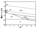
- FIG. 1 is a potential-pH diagram of titanium (Ti).
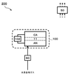
- FIG. 2 is a diagram showing an example of the hydrogen system of the first embodiment.
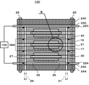
- FIG. 3A is a diagram showing an example of an electrochemical hydrogen pump of the hydrogen system of the first embodiment.
- FIG. 3B is an enlarged view of a portion B of the electrochemical hydrogen pump of FIG. 3A.
- FIG. 4A is a diagram showing an example of an electrochemical hydrogen pump of the hydrogen system of the first embodiment.
- FIG. 4B is an enlarged view of a portion B of the electrochemical hydrogen pump of FIG. 4A.
- FIG. 5 is a pH-potential diagram of titanium (Ti) prepared based on a verification experiment.
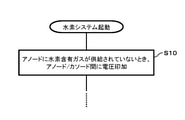
- FIG. 6 is a flowchart showing an example of the operation of the hydrogen system of the first embodiment.
- FIG. 6 is a flowchart showing an example of the operation of the hydrogen system of the first embodiment.
- FIG. 7A is a flowchart showing an example of the operation of the hydrogen system of the first embodiment of the first embodiment.
- FIG. 7B is a flowchart showing an example of the operation of the hydrogen system of the second embodiment of the first embodiment.
- FIG. 8 is a diagram showing an example of the hydrogen system of the second embodiment.
- FIG. 9 is a diagram showing an example of the hydrogen system of the third embodiment.
- FIG. 10 is a flowchart showing an example of the operation of the hydrogen system of the third embodiment.
- FIG. 11 is a flowchart showing an example of the operation of the hydrogen system of the first embodiment of the fourth embodiment.
- FIG. 12 is a flowchart showing an example of the operation of the hydrogen system of the second embodiment of the fourth embodiment.
- FIG. 13 is a flowchart showing an example of the operation of the hydrogen system according to the third embodiment of the fourth embodiment.
- FIG. 14 is a flowchart showing an example of the operation of the hydrogen system of the first embodiment of the fifth embodiment.
- FIG. 15 is a flowchart showing an example of the operation of the hydrogen system of the second embodiment of the fifth embodiment.
- Patent Document 2 proposes titanium as an example of an electrode material for an anode to which a positive potential is given. The reason for this is that when the titanium potential is a positive potential, a dense thin film of TiO 2 is formed on titanium. As a result, the anode has high corrosion resistance.
- the anode potential when a voltage is not applied between the anode and the cathode, the anode potential may become a negative potential due to the hydrogen partial pressure of each of the anode and the cathode of the compressor.
- the amount of outside air entering the cathode may be larger than the amount of outside air entering the anode. ..
- the hydrogen partial pressure of the anode becomes higher than the hydrogen partial pressure of the cathode, so that the anode potential may become a negative potential.
- titanium ions may modify the sulfonic acid groups in the electrolyte membrane by elution of titanium into water. This can irreversibly reduce the proton conductivity of the electrolyte membrane.
- titanium surface is coated with a noble metal that does not easily elute into water in an acidic state by using plating or a CVD coat, it is difficult to completely coat the titanium surface with the noble metal. it is conceivable that. If pinholes are present in this film, titanium may be eluted into water through the pinholes, and titanium ions may be ion-exchanged with the sulfonic acid groups in the electrolyte membrane to promote deterioration of the electrolyte membrane. There is.
- anode gas diffusion layer is made of an electrode material containing a metal other than titanium. Specific examples of such an electrode material will be described in the embodiments.
- the hydrogen system of the first aspect of the present disclosure includes an electrolyte membrane, an anode catalyst layer provided on one main surface of the electrolyte membrane, a cathode catalyst layer provided on the other main surface of the electrolyte membrane, and an anode catalyst. Between the anode catalyst layer and the cathode catalyst layer and at least one cell including an anodic gas diffusion layer provided on the layer and containing a porous sheet containing a metal and a cathode gas diffusion layer provided on the cathode catalyst layer.
- a voltage applicator that applies a voltage to the anode is provided, and by applying a voltage with the voltage applicator, hydrogen in the hydrogen-containing gas supplied to the anode is moved to the cathode via the electrolyte membrane, and compressed hydrogen is produced. It includes a compressor for generating and a controller for applying the above voltage by a voltage applicator after stopping or starting.
- the hydrogen system of this embodiment can suppress deterioration of the electrolyte membrane as compared with the conventional case.
- the hydrogen system of this embodiment is compared with the case where such voltage control is not performed by applying a voltage between the anode catalyst layer and the cathode catalyst layer by a voltage adapter at a timely time after stopping or starting. Therefore, it becomes difficult for the anode potential of the compressor to become a negative potential. Then, the hydrogen system of this embodiment can suppress the elution of the metal contained in the porous sheet into water. As a result, the hydrogen system of this embodiment can reduce the possibility of metal ions modifying the sulfonic acid groups in the electrolyte membrane, so that deterioration of the electrolyte membrane is suppressed as compared with the conventional case.
- the hydrogen partial pressure of the anode may be higher than the hydrogen partial pressure of the cathode.
- the hydrogen partial pressure of the anode may be higher than the hydrogen partial pressure of the cathode.
- the controller may apply the above voltage by the voltage applyer.
- the supply of the hydrogen-containing gas to the anode is stopped, and then the above voltage is applied by the voltage applyer, so that the metal ion can be compared with the case where the voltage control is not performed. Elution is suppressed, and as a result, metal ions are suppressed from ion exchange with the protons of the sulfonic acid group in the electrolyte membrane. As a result, the electrolyte membrane is less likely to deteriorate.
- the controller in the hydrogen system of the third aspect of the present disclosure, after the cathode off gas is discharged from the cathode to a discharge destination different from the hydrogen demander, the controller applies the above voltage by the voltage applyer. May be good.
- the hydrogen partial pressure of the anode may become higher than the hydrogen partial pressure of the cathode.
- the cathode off gas is discharged from the cathode to a discharge destination different from that of the hydrogen demander, and then the amount of outside air mixed into the cathode from the outside becomes larger than the amount of outside air mixed into the anode from the outside, the hydrogen partial pressure of the anode becomes the cathode. It may be higher than the partial pressure of hydrogen in.
- the metal ions contained in the anode gas diffusion layer are eluted, and the metal ions may be ion-exchanged with the protons of the sulfonic acid groups in the electrolyte membrane. As a result, the electrolyte membrane may deteriorate.
- the cathode off gas when the cathode off gas is discharged from the cathode to a discharge destination different from that of the hydrogen demand body after the shutdown, and then the voltage is applied by the voltage adapter to perform such voltage control.
- the voltage is applied by the voltage adapter to perform such voltage control.
- elution of metal ions is suppressed, and as a result, ion exchange of metal ions with the protons of the sulfonic acid group in the electrolyte membrane is suppressed.
- the electrolyte membrane is less likely to deteriorate.
- the hydrogen system of the fourth aspect of the present disclosure may contain titanium in the hydrogen system of any one of the first to third aspects.
- the porous sheet is made of titanium, so that a dense thin film of TIO 2 is formed on titanium when the titanium potential is positive.
- the hydrogen system of this embodiment can obtain an anode gas diffusion layer having high corrosion resistance in an acidic environment.
- the hydrogen system of the fifth aspect of the present disclosure is the hydrogen system of any one of the first to the fourth aspects, in which the controller applies a voltage smaller than the maximum voltage applied during operation after the stop. It may be applied by.
- the hydrogen system of this embodiment is the maximum voltage applied during operation as the voltage applied between the anode catalyst layer and the cathode catalyst layer in order to suppress the deterioration of the electrolyte film after the shutdown.
- maximum voltage By selecting a voltage smaller than (hereinafter, maximum voltage), it is possible to reduce the power consumed by the voltage applyer as compared with the case where the maximum voltage is applied between the two after stopping.
- the cathode pressure reaches the supply pressure of compressed hydrogen to the hydrogen consumer after the controller is stopped.
- a voltage smaller than the applied voltage at the time may be applied by the voltage applicator.
- the cathode pressure is the voltage applied between the anode catalyst layer and the cathode catalyst layer in order to suppress the deterioration of the electrolyte film after the shutdown, and the cathode pressure is the compressed hydrogen to the hydrogen demander.
- an electrochemical compressor when a voltage for suppressing deterioration of the electrolyte membrane is applied between the anode catalyst layer and the cathode catalyst layer after stopping, hydrogen moves from the anode to the cathode through the electrolyte membrane. do. Then, as the amount of hydrogen present in the anode decreases, the pressure in the anode decreases, so that the anode may become negative pressure. If air enters the anode from the outside due to the negative pressure of the anode, the cell of the compressor may deteriorate.
- the hydrogen system of the seventh aspect of the present disclosure includes a flow rate regulator for adjusting the flow rate of the hydrogen-containing gas supplied to the anode in any one of the hydrogen systems of the first aspect to the sixth aspect, and after stopping.
- the controller controls the flow regulator to supply the anode with the hydrogen-containing gas at a flow rate smaller than the flow rate of the hydrogen-containing gas supplied to the anode during operation. You may.
- the hydrogen system of this embodiment when a voltage is applied between the anode catalyst layer and the cathode catalyst layer in order to suppress deterioration of the electrolyte membrane after shutdown, hydrogen is applied from the anode to the cathode through the electrolyte membrane. Even if it moves, the hydrogen-containing gas can be charged to the anode by using the flow rate regulator. Then, the possibility that the anode becomes negative pressure after stopping is reduced.
- the flow rate of the hydrogen-containing gas input to the anode is adjusted to the anode during operation. It can be made smaller than the flow rate of the hydrogen-containing gas supplied to.
- the hydrogen system of the eighth aspect of the present disclosure includes a flow rate regulator for adjusting the flow rate of the hydrogen-containing gas supplied to the anode in any one of the hydrogen systems of the first to sixth aspects, and applies a voltage after stopping.
- the controller controls the flow regulator and does not have to supply the hydrogen-containing gas to the anode.
- the hydrogen system of the present embodiment can reduce the consumption of the hydrogen-containing gas from the hydrogen-containing gas source as compared with the hydrogen system of the seventh aspect.
- the supply source of the hydrogen-containing gas include a hydrogen tank, a hydrogen infrastructure, and a water electrolyzer.
- the hydrogen system of the ninth aspect of the present disclosure corresponds to the amount of hydrogen returning from the cathode to the anode via the electrolyte membrane after the controller is stopped in any one of the hydrogen systems of the first to the eighth aspects.
- the voltage required to transfer the amount of hydrogen from the anode to the cathode may be applied by a voltage applyer.
- the voltage applied between the anode catalyst layer and the cathode catalyst layer in order to suppress the deterioration of the electrolyte membrane is passed through the electrolyte membrane by the differential pressure between the cathode and the anode.
- the hydrogen system of the tenth aspect of the present disclosure comprises a first flow path for supplying the cathode off gas discharged from the cathode of the compressor to the anode in any one of the hydrogen systems of the first aspect to the ninth aspect.
- a first on-off valve provided in the first flow path, a second on-flow path through which the anode off gas discharged from the anode of the compressor flows, and a second on-off valve provided in the second flow path are provided and stopped.
- the controller may open the first on-off valve and close the second on-off valve before or when the voltage is applied later by the voltage applyer.
- the hydrogen system of this embodiment is present in the cathode off gas existing in the cathode of the compressor and the anode of the compressor via the first flow path by opening the first on-off valve after stopping. It can be mixed with the anodic gas to be used. Then, even if the amount of outside air entering the cathode is larger than the amount of outside air entering the anode after the system is stopped and after the gas existing in the cathode is released, the hydrogen partial pressure of the anode and the hydrogen partial pressure of the cathode are then increased. The difference is reduced.
- the first on-off valve is opened, the second on-off valve is closed, and a voltage is applied between the anode catalyst layer and the cathode catalyst layer by the voltage applyer to compress the hydrogen system. Since the gas present in each of the anode and cathode of the machine circulates in the compressor and in the first flow path, the difference in hydrogen partial pressure between the anode and cathode is further reduced.
- the anode potential is less likely to become a negative potential, so that deterioration of the electrolyte membrane is suppressed. Further, in the hydrogen system of this embodiment, the difference in dryness and humidity between the main surface region on the anode side and the main surface region on the cathode side in the electrolyte membrane is rapidly reduced, so that mechanical deterioration of the electrolyte membrane is suppressed.
- the controller applies a voltage of 1/10 or less of the maximum voltage applied during operation after stopping. It may be applied by a voltage applyer.
- a voltage of 1/10 or less of the maximum voltage is selected as the voltage applied between the anode catalyst layer and the cathode catalyst layer in order to suppress the deterioration of the electrolyte film after the shutdown.
- the hydrogen system of the twelfth aspect of the present disclosure is the hydrogen system of any one of the first to tenth aspects, in which the controller applies a voltage of 0.1 V or less per cell by a voltage applyer after the controller is stopped. You may.
- a voltage of 0.1 V or less per cell is selected as the voltage applied between the anode catalyst layer and the cathode catalyst layer in order to suppress the deterioration of the electrolyte film after the shutdown.
- the hydrogen system of the thirteenth aspect of the present disclosure is the case where the voltage applied by the voltage adapter after the stop is not applied by the voltage adapter after the stop in any one of the hydrogen systems of the first to the twelfth aspects. It may be a voltage required to make the anode potential of the compressor assumed to be 0 V or more.
- the voltage applied between the anode catalyst layer and the cathode catalyst layer in order to suppress the deterioration of the electrolyte film after the shutdown is the voltage between them by the voltage adapter after the shutdown.
- FIG. 1 shows the calculation results of a general “titanium pH-potential diagram” in water at 25 ° C., assuming that the activity of Ti 3+ is 1 ⁇ 10 -6 mol / L. It's just doing. Therefore, the present disclosers can apply a voltage between the anode and the cathode at an appropriate timing when the hydrogen system is started, based on the calculation result of the general “titanium pH-potential diagram” shown in FIG. I thought it was difficult. The process leading to this determination will be described in the verification experiment of the embodiment.
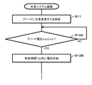
- the controller applies the above voltage by the voltage adapter when the hydrogen-containing gas is not supplied to the anode at the time of starting. May be good.
- the hydrogen system of this embodiment can suppress deterioration of the electrolyte membrane as compared with the conventional case.
- the hydrogen partial pressure of the anode may be higher than the hydrogen partial pressure of the cathode.
- the hydrogen partial pressure at the anode may be higher than the hydrogen partial pressure at the cathode.
- the metal ions contained in the anode gas diffusion layer are eluted, and the metal ions may be ion-exchanged with the protons of the sulfonic acid groups in the electrolyte membrane. As a result, the electrolyte membrane may deteriorate.
- the hydrogen-containing gas when the hydrogen-containing gas is not supplied to the anode at the time of starting, the above voltage is applied by the voltage applicator, so that the metal ion can be compared with the case where the voltage control is not performed. Elution is suppressed, and as a result, metal ions are suppressed from ion exchange with the protons of the sulfonic acid group in the electrolyte membrane. As a result, the electrolyte membrane is less likely to deteriorate.
- the controller may apply the voltage by the voltage applicator when the potential is higher than the predetermined potential or within the predetermined time after the potential becomes lower than the predetermined potential.
- the hydrogen system of this embodiment can suppress deterioration of the electrolyte membrane as compared with the conventional case. Specifically, if the amount of outside air mixed into the cathode increases after the hydrogen system is stopped, if a hydrogen-containing gas is supplied to the anode at startup, the hydrogen content of the anode will increase over time.
- the pressure can be higher than the hydrogen partial pressure of the cathode. Therefore, when the potential of the anode is larger than the potential at which the metal ions are eluted, in other words, before the potential of the anode is equal to or lower than the potential at which the metal ions are eluted, the voltage is applied by the voltage adapter.
- the above voltage is applied by the voltage adapter within a predetermined time after the potential of the anode becomes equal to or lower than the potential at which the metal ion elutes.
- the voltage it is possible to shorten the period during which the potential of the anode is equal to or lower than the potential at which the metal ion elutes, as compared with the case where such voltage control is not performed. As a result, the progress of deterioration of the electrolyte membrane is appropriately suppressed.
- the metal in any one of the 1st aspect, the 14th aspect and the 15th aspect, the metal may contain titanium.
- the porous sheet is made of titanium, so that a dense thin film of TIO 2 is formed on titanium when the titanium potential is positive.
- the hydrogen system of this embodiment can obtain an anode gas diffusion layer having high corrosion resistance in an acidic environment.
- nitrogen or air is applied to the cathode before the voltage is applied by the voltage applyer. It may be filled.
- the hydrogen partial pressure of the anode may be higher than the hydrogen partial pressure of the cathode. Then, the metal ions contained in the anode gas diffusion layer are eluted, and the metal ions may be ion-exchanged with the protons of the sulfonic acid groups in the electrolyte membrane. As a result, the electrolyte membrane may deteriorate.
- the above voltage is applied by a voltage applyer. Then, the elution of the metal ion is suppressed as compared with the case where such voltage control is not performed, and as a result, the ion exchange of the metal ion with the proton of the sulfonic acid group in the electrolyte membrane is suppressed. As a result, the electrolyte membrane is less likely to deteriorate.
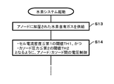
- the controller controls the current density flowing through the cell to compress the operation.
- the voltage applyer may be controlled so that it is maintained below the first threshold value, which is smaller than the target current density at the time, and below the second threshold value, which is smaller than the target pressure during the compression operation.
- the electrolyte membrane When the electrolyte membrane is dry when the hydrogen system is activated, the electrolyte membrane is localized when the current density flowing through the cell exceeds the first threshold without increasing the water content of the electrolyte membrane to an appropriate value.
- the electrolyte membrane may become hot and deteriorate in the dry part.
- the electrolyte membrane when the electrolyte membrane is dry when the hydrogen system is activated, if the cathode pressure exceeds the second threshold value without increasing the water content of the electrolyte membrane to an appropriate value, the electrolyte membrane is ruptured. May occur.
- the hydrogen system of this embodiment operates in the hydrogen-containing gas while maintaining the current density flowing through the cell and the pressure of the cathode below the first threshold value and below the second threshold value, respectively, at the time of starting.
- the 19th aspect hydrogen system of the present disclosure is a voltage applyer in the 18th aspect hydrogen system in order to keep the current density flowing through the cell below the first threshold value and the cathode pressure below the second threshold value.
- the controller may increase the applied voltage of the voltage applicator so that at least one of the current density flowing through the cell and the pressure of the cathode increases.
- the increase in the water content of the electrolyte membrane can be confirmed, for example, by the decrease in the applied voltage of the voltage applyer. Therefore, in the operation of maintaining the current density flowing through the cell and the pressure of the cathode below the first threshold value and below the second threshold value, respectively, in the hydrogen system of this embodiment, when the voltage applied by the voltage applyer decreases, The voltage applied to the voltage adapter is increased so that at least one of the current density flowing through the cell and the pressure of the cathode increases. Thereby, the hydrogen system of this embodiment can increase at least one of the current density flowing through the cell and the pressure of the cathode in a timely manner as the water content of the electrolyte membrane increases.
- the method of operating the hydrogen system according to the twentieth aspect of the present disclosure is to apply a voltage between the anode and the cathode, which include an anode gas diffusion layer containing a porous sheet containing a metal, which is provided with an electrolyte membrane interposed therebetween. It is provided with a step of moving hydrogen in the hydrogen-containing gas supplied to the cathode to the cathode to generate compressed hydrogen, and a step of applying a voltage between the anode and the cathode at the time of stopping or starting.
- the operation method of the hydrogen system of this embodiment can suppress the deterioration of the electrolyte membrane as compared with the conventional method. Since the details of the action and effect of the operation method of the hydrogen system of this embodiment are the same as those of the above-mentioned hydrogen system, the description thereof will be omitted.
- the method for operating the hydrogen system according to the 21st aspect of the present disclosure is the method for operating the hydrogen system according to the 20th aspect, even if a voltage is applied between the anode and the cathode after the supply of the hydrogen-containing gas to the anode is stopped. good.
- the method for operating the hydrogen system according to the 22nd aspect of the present disclosure is the method for operating the hydrogen system according to the 20th aspect, in which the cathode off gas is discharged from the cathode to a discharge destination different from the hydrogen demander, and then a voltage is applied between the anode and the cathode. It may be applied.
- the method of operating the hydrogen system according to the 23rd aspect of the present disclosure is the method of operating the hydrogen system according to the 20th aspect, in which a voltage is applied between the anode and the cathode when the hydrogen-containing gas is not supplied to the anode at the time of starting. You may.
- the potential of the anode is included in the anode gas diffusion layer.
- a voltage may be applied between the anode and the cathode when the potential at which the metal ions elute is greater than the predetermined potential or within a predetermined time after the potential falls below the predetermined potential.
- FIG. 2 is a diagram showing an example of the hydrogen system of the first embodiment.
- the hydrogen system 200 of the present embodiment includes an electrochemical hydrogen pump 100 and a controller 50.
- the electrochemical hydrogen pump 100 applies a voltage between the anode catalyst layer 13 and the cathode catalyst layer 12 (see FIGS. 3B and 4B) by the voltage applicator 102 in the hydrogen-containing gas supplied to the anode AN. It is a device that transfers hydrogen to the cathode CA via the electrolyte membrane 11 to generate compressed hydrogen.
- the electrochemical hydrogen pump 100 may include a stack in which a plurality of MEAs (cells) are stacked. The detailed configuration of the electrochemical hydrogen pump 100 will be described later.
- Examples of the hydrogen-containing gas include a low-pressure reformed gas generated by a reforming reaction such as methane gas, and a low-pressure hydrogen gas containing water vapor generated by electrolysis of water.
- the controller 50 applies a voltage between the anode catalyst layer 13 and the cathode catalyst layer 12 by the voltage applicator 102 after stopping or starting.
- the controller 50 may control the overall operation of the hydrogen system 200.
- the "stop" of the hydrogen system 200 means the stop of the compression operation for supplying the compressed hydrogen generated by the cathode CA from the cathode CA of the electrochemical hydrogen pump 100 to the hydrogen demanding body.
- hydrogen demanders include hydrogen reservoirs, fuel cells, and hydrogen infrastructure piping.
- the hydrogen reservoir include a dispenser installed in a hydrogen station, a hydrogen tank, and the like.
- "at startup” of the hydrogen system 200 means that the operation of auxiliary equipment such as valves and pumps provided in the hydrogen system 200 is started, and the current flowing through the electrochemical cell 100B of the electrochemical hydrogen pump 100 is the hydrogen system. It refers to the operation until the target current is reached during the compression operation of 200.
- "During the compressed operation” means that the operation for supplying the compressed hydrogen generated by the cathode CA from the cathode CA of the electrochemical hydrogen pump 100 to the hydrogen demanding body is in operation.
- the "startup" of the hydrogen system 200 may be started at the timing when an appropriate start signal is input to the controller 50. Specifically, for example, when an operator makes a start request via an input device (not shown), a start signal is input to the controller 50.
- the input device may be provided in the hydrogen system 200, or may be an external input device (for example, a mobile terminal such as a smartphone) not provided in the hydrogen system 200. Further, when the "startup" of the hydrogen system 200 is completed, the supply (compression operation) of the compressed hydrogen generated by the cathode CA to the hydrogen demander may be started in a timely manner.
- the controller 50 includes, for example, an arithmetic circuit and a storage circuit for storing a control program.
- Examples of the arithmetic circuit include an MPU and a CPU.
- Examples of the storage circuit include a memory and the like.
- the controller 50 may be composed of a single controller that performs centralized control, or may be composed of a plurality of controllers that perform distributed control in cooperation with each other.
- FIG. 3A and 4A are diagrams showing an example of an electrochemical hydrogen pump of the hydrogen system of the first embodiment.
- FIG. 3B is an enlarged view of a portion B of the electrochemical hydrogen pump of FIG. 3A.
- FIG. 4B is an enlarged view of a portion B of the electrochemical hydrogen pump of FIG. 4A.
- FIG. 3A shows a vertical cross section of the electrochemical hydrogen pump 100 including a straight line passing through the center of the electrochemical hydrogen pump 100 and the center of the cathode gas lead-out manifold 28 in a plan view.
- FIG. 4A shows the vertical direction of the electrochemical hydrogen pump 100 including a straight line passing through the center of the electrochemical hydrogen pump 100, the center of the anode gas introduction manifold 27, and the center of the anode gas lead-out manifold 30 in a plan view.
- a cross section is shown.
- the electrochemical hydrogen pump 100 includes at least one electrochemical cell 100B.
- the electrochemical cell 100B includes an electrolyte membrane 11, an anode AN, and a cathode CA, and in the hydrogen pump unit 100A, the electrolyte membrane 11, the anode catalyst layer 13, and the cathode catalyst layer are included.
- the anode gas diffusion layer 15, the cathode gas diffusion layer 14, the anode separator 17, and the cathode separator 16 are laminated.
- the number of hydrogen pump units 100A is not limited to this. That is, the number of hydrogen pump units 100A can be set to an appropriate number based on operating conditions such as the amount of hydrogen compressed by the electrochemical hydrogen pump 100.
- the anode AN is provided on one main surface of the electrolyte membrane 11.
- the anode AN is an electrode including an anode catalyst layer 13 and an anode gas diffusion layer 15.
- an annular seal member 43 is provided so as to surround the periphery of the anode catalyst layer 13, and the anode catalyst layer 13 is appropriately sealed by the seal member 43.
- the cathode CA is provided on the other main surface of the electrolyte membrane 11.
- the cathode CA is an electrode including a cathode catalyst layer 12 and a cathode gas diffusion layer 14.
- an annular seal member 42 is provided so as to surround the periphery of the cathode catalyst layer 12, and the cathode catalyst layer 12 is appropriately sealed by the seal member 42.
- the electrolyte membrane 11 is sandwiched between the anode AN and the cathode CA so as to be in contact with each of the anode catalyst layer 13 and the cathode catalyst layer 12.
- the electrolyte membrane 11 may have any structure as long as it has proton conductivity.
- examples of the electrolyte membrane 11 include a sulfonic acid-modified fluoropolymer electrolyte membrane, a hydrocarbon-based electrolyte membrane, and the like.
- the electrolyte membrane 11 for example, Nafion (registered trademark, manufactured by DuPont), Aciplex (registered trademark, manufactured by Asahi Kasei Corporation) and the like can be used, but the electrolyte membrane 11 is not limited thereto.
- the anode catalyst layer 13 is provided on one main surface of the electrolyte membrane 11.
- the anode catalyst layer 13 contains, but is not limited to, carbon capable of supporting a catalyst metal (for example, platinum) in a dispersed state.
- the cathode catalyst layer 12 is provided on the other main surface of the electrolyte membrane 11.
- the cathode catalyst layer 12 contains, but is not limited to, carbon capable of supporting a catalyst metal (for example, platinum) in a dispersed state.
- the method for preparing the catalyst for both the cathode catalyst layer 12 and the anode catalyst layer 13 various methods can be mentioned, but the method is not particularly limited.
- examples of the carbon-based powder include powders such as graphite, carbon black, and conductive activated carbon.
- the method of supporting platinum or other catalytic metal on the carbon carrier is not particularly limited.
- a method such as powder mixing or liquid phase mixing may be used.
- Examples of the latter liquid phase mixing include a method in which a carrier such as carbon is dispersed in a colloidal liquid as a catalyst component and adsorbed.
- the supported state of the catalyst metal such as platinum on the carbon carrier is not particularly limited.
- the catalyst metal may be atomized and supported on a carrier with high dispersion.
- the cathode gas diffusion layer 14 is provided on the cathode catalyst layer 12.
- the cathode gas diffusion layer is made of a porous material and has conductivity and gas diffusivity. It is desirable that the cathode gas diffusion layer has elasticity so as to appropriately follow the displacement and deformation of the constituent members generated by the differential pressure between the cathode CA and the anode AN during the operation of the electrochemical hydrogen pump 100.
- As the base material of the cathode gas diffusion layer for example, a carbon fiber sintered body or the like can be used, but the substrate is not limited thereto.
- the anode gas diffusion layer 15 is provided on the anode catalyst layer 13 and includes a porous sheet 15S containing a metal. That is, the porous sheet 15S is made of a metal material and has conductivity and gas diffusivity. Further, it is desirable that the porous sheet 15S has a rigidity sufficient to withstand the pressing of the electrolyte membrane 11 due to the above-mentioned differential pressure when the electrochemical hydrogen pump 100 is operated.
- titanium can be used as the material of the porous sheet 15S, but the material is not limited thereto.
- a metal material such as chromium, nickel, tungsten, tantalum, iron, and manganese can also be used.
- a dense thin film of TiO 2 is formed on titanium when the titanium potential is positive.
- the hydrogen system 200 of the present embodiment can obtain the anode gas diffusion layer 15 having high corrosion resistance in an acidic environment.
- the anode gas diffusion layer 15 may be laminated with two or more types of porous sheets.
- the layers of the porous sheet may be joined by diffusion joining or the like.
- the porous sheet on the electrolyte membrane 11 side of the anode gas diffusion layer 15 may be made of titanium
- the porous sheet on the anode separator 17 side may be made of stainless steel or the like.
- the porous sheet on the electrolyte membrane 11 side is made of titanium, the anode gas diffusion layer 15 having high corrosion resistance can be obtained in an acidic environment as described above.
- anode gas diffusion layer 15 is provided with a conductive coating on at least both main surfaces of the porous sheet 15S in order to secure desired conductivity between the anode catalyst layer 13 and the anode separator 17.
- both main surfaces of the porous sheet 15S may be covered with a highly conductive sheet-like coating film by plating or CVD coating, or the surface of the electrode particles constituting the porous sheet 15S.
- it may be covered with a highly conductive coating film.
- a coating film examples include, but are not limited to, a platinum-plated film having a low resistance.
- a platinum-plated film having a low resistance examples include, but are not limited to, a platinum-plated film having a low resistance.
- other noble metals such as gold and ruthenium, diamond-like carbon, metal carbides, metal nitrides and the like can also be used.
- the thickness of the coating film may be set to 1/100 or less of the thickness of the porous sheet 15S.
- the thickness of such a coating film can be measured by, for example, fluorescent X-ray analysis.
- the anode separator 17 is a member provided on the anode gas diffusion layer 15 of the anode AN.
- the cathode separator 16 is a member provided on the cathode gas diffusion layer 14 of the cathode CA.
- a recess is provided in the central portion of each of the cathode separator 16 and the anode separator 17.
- a cathode gas diffusion layer 14 and an anode gas diffusion layer 15 are housed in each of these recesses.
- the hydrogen pump unit 100A is formed by sandwiching the above-mentioned electrochemical cell 100B between the cathode separator 16 and the anode separator 17.
- the main surface of the cathode separator 16 in contact with the cathode gas diffusion layer 14 is formed of a flat surface without providing a cathode gas flow path.
- the contact area between the cathode gas diffusion layer 14 and the cathode separator 16 can be increased as compared with the case where the cathode gas flow path is provided on the main surface of the cathode separator 16.
- the electrochemical hydrogen pump 100 can reduce the contact resistance between the cathode gas diffusion layer 14 and the cathode separator 16.
- a serpentine-shaped anode gas flow path including a plurality of U-shaped folded portions and a plurality of linear portions. 33 is provided on the main surface of the anode separator 17 in contact with the porous sheet 15S.
- the straight line portion of the anode gas flow path 33 extends in the direction perpendicular to the paper surface of FIG. 4A.
- an anode gas flow path 33 is an example and is not limited to this example.
- the anode gas flow path may be composed of a plurality of linear flow paths.
- annular and flat plate-shaped insulator 21 provided so as to surround the periphery of the electrochemical cell 100B is sandwiched between the conductive cathode separator 16 and the anode separator 17. This prevents a short circuit between the cathode separator 16 and the anode separator 17.
- the electrochemical hydrogen pump 100 includes a first end plate and a second end plate provided on both ends in the stacking direction in the hydrogen pump unit 100A, and the hydrogen pump unit 100A, the first end plate and the second end plate. 25 is provided with a fastener 25 for fastening the two in the stacking direction.
- the cathode end plate 24C and the anode end plate 24A correspond to the above-mentioned first end plate and second end plate, respectively. That is, the anode end plate 24A is an end plate provided on the anode separator 17 located at one end in the stacking direction in which the members of the hydrogen pump unit 100A are laminated. Further, the cathode end plate 24C is an end plate provided on the cathode separator 16 located at the other end in the stacking direction in which the members of the hydrogen pump unit 100A are laminated.
- the fastener 25 may have any configuration as long as the hydrogen pump unit 100A, the cathode end plate 24C and the anode end plate 24A can be fastened in the stacking direction.
- the fastener 25 may be a bolt, a nut with a disc spring, or the like.
- the cathode gas lead-out manifold 28 has a through hole provided in each member of the three hydrogen pump units 100A and the cathode end plate 24C, and a non-through hole provided in the anode end plate 24A. It is composed of a series. Further, the cathode end plate 24C is provided with a cathode gas lead-out path 26.
- the cathode gas lead-out path 26 may be composed of a pipe through which the cathode off gas discharged from the cathode CA flows. The cathode gas lead-out path 26 communicates with the cathode gas lead-out manifold 28.
- the cathode gas lead-out manifold 28 communicates with each cathode CA of the hydrogen pump unit 100A via each of the cathode gas passage paths 34.
- the compressed hydrogen generated in each cathode CA of the hydrogen pump unit 100A passes through each of the cathode gas passage paths 34 and then joins in the cathode gas lead-out manifold 28. Then, the merged compressed hydrogen is guided to the cathode gas derivation path 26.
- each cathode CA of the hydrogen pump unit 100A communicates with each other via the respective cathode gas passage path 34 and the cathode gas lead-out manifold 28 of the hydrogen pump unit 100A.
- An O-ring is placed between the cathode separator 16 and the anode separator 17, between the cathode separator 16 and the cathode feeding plate 22C, and between the anode separator 17 and the anode feeding plate 22A so as to surround the cathode gas lead-out manifold 28 in a plan view.
- An annular sealing member 40 such as the above is provided, and the cathode gas lead-out manifold 28 is appropriately sealed by the sealing member 40.
- the anode end plate 24A is provided with an anode gas introduction path 29.
- the anode gas introduction path 29 may be composed of a pipe through which a hydrogen-containing gas supplied to the anode AN flows.
- the anode gas introduction path 29 communicates with the cylindrical anode gas introduction manifold 27.
- the anode gas introduction manifold 27 is composed of each member of the three hydrogen pump units 100A and a series of through holes provided in the anode end plate 24A.
- the anode gas introduction manifold 27 communicates with one end of each anode gas flow path 33 of the hydrogen pump unit 100A via each of the first anode gas passage path 35.
- the hydrogen-containing gas supplied from the anode gas introduction path 29 to the anode gas introduction manifold 27 is distributed to each of the hydrogen pump units 100A through the first anode gas passage paths 35 of the hydrogen pump unit 100A. Then, while the distributed hydrogen-containing gas passes through the anode gas flow path 33, the hydrogen-containing gas is supplied from the anode gas diffusion layer 15 to the anode catalyst layer 13.
- the anode end plate 24A is provided with an anode gas lead-out path 31.
- the anode gas lead-out path 31 may be composed of a pipe through which a hydrogen-containing gas discharged from the anode AN flows.
- the anode gas lead-out path 31 communicates with the cylindrical anode gas lead-out manifold 30.
- the anode gas lead-out manifold 30 is composed of each member of the three hydrogen pump units 100A and a series of through holes provided in the anode end plate 24A.
- the anode gas lead-out manifold 30 communicates with the other end of each anode gas flow path 33 of the hydrogen pump unit 100A via each of the second anode gas passage paths 36.
- the hydrogen-containing gas that has passed through the respective anode gas flow paths 33 of the hydrogen pump unit 100A is supplied to the anode gas lead-out manifold 30 through each of the second anode gas passage paths 36, and is merged there. Then, the merged hydrogen-containing gas is guided to the anode gas lead-out path 31.
- An anode gas introduction manifold 27 and an anode gas lead-out manifold 30 are provided between the cathode separator 16 and the anode separator 17, between the cathode separator 16 and the cathode feeding plate 22C, and between the anode separator 17 and the anode feeding plate 22A in a plan view.
- An annular sealing member 40 such as an O-ring is provided so as to surround the anode gas introduction manifold 27 and the anode gas lead-out manifold 30 are appropriately sealed by the sealing member 40.
- the electrochemical hydrogen pump 100 includes a voltage adapter 102.
- the voltage applyer 102 is a device that applies a voltage between the anode catalyst layer 13 and the cathode catalyst layer 12. Specifically, the high potential of the voltage applicator 102 is applied to the anode catalyst layer 13, and the low potential of the voltage applicator 102 is applied to the cathode catalyst layer 12.
- the voltage adapter 102 may have any configuration as long as a voltage can be applied between the anode catalyst layer 13 and the cathode catalyst layer 12.
- the voltage applyer 102 may be a device that adjusts the voltage applied between the anode catalyst layer 13 and the cathode catalyst layer 12.
- the voltage adapter 102 includes a DC / DC converter when connected to a DC power source such as a battery, a solar cell, or a fuel cell, and AC when connected to an AC power source such as a commercial power source. It is equipped with a / DC converter.
- the voltage applyer 102 has, for example, a voltage applied between the anode catalyst layer 13 and the cathode catalyst layer 12, the anode catalyst layer 13 and the like so that the electric power supplied to the hydrogen pump unit 100A becomes a predetermined set value. It may be a power supply type power source in which the current flowing between the cathode catalyst layers 12 is adjusted.
- the terminal on the low potential side of the voltage adapter 102 is connected to the cathode feeding plate 22C, and the terminal on the high potential side of the voltage adapter 102 is connected to the anode feeding plate 22A.
- the cathode feeding plate 22C is electrically connected to the cathode separator 16 located at the other end in the stacking direction, and is arranged with the cathode end plate 24C via the cathode insulating plate 23C.
- the anode feeding plate 22A is electrically connected to the anode separator 17 located at one end in the above-mentioned stacking direction, and is arranged with the anode end plate 24A via the anode insulating plate 23A.
- the hydrogen system 200 is provided with, for example, a temperature detector that detects the temperature of the electrochemical hydrogen pump 100, a pressure detector that detects the pressure of hydrogen compressed by the cathode CA of the electrochemical hydrogen pump 100, and the like. There is.
- the hydrogen system 200 is provided with valves and the like for opening and closing these paths at appropriate positions of the anode gas introduction path 29, the anode gas lead-out path 31 and the cathode gas lead-out path 26.
- the above-mentioned configuration of the electrochemical hydrogen pump 100 and the configuration of the hydrogen system 200 are examples, and are not limited to this example.
- the electrochemical hydrogen pump 100 does not provide the anode gas lead-out manifold 30 and the anode gas lead-out path 31, and all of the hydrogen (H 2 ) in the hydrogen-containing gas supplied to the anode AN through the anode gas introduction manifold 27 is the cathode.
- a dead-end structure that compresses with CA may be adopted.
- FIG. 1 shows the calculated values of a typical titanium pH-potential diagram in water at 25 ° C., assuming that the activity of Ti 3+ is 1 ⁇ 10 -6 mol / L. Not too much.
- the cell temperature of the electrochemical hydrogen pump 100 is generally maintained at a high temperature of about 50 ° C to 80 ° C. Further, in the anode AN of the electrochemical hydrogen pump 100, a hydrogen-containing gas in a highly humidified state is distributed. Therefore, it is difficult to accurately grasp the stable region of titanium ions corresponding to the above-mentioned usage environment of the electrochemical hydrogen pump 100 from FIG.
- the titanium potential with respect to the reference electrode is about ⁇ 0.10 V and about ⁇ 0.10 V at a temperature of about 50 ° C. to about 80 ° C. and a pH of 0.05.
- a verification experiment was conducted to confirm the presence or absence of titanium ion elution in each case of -0.42 V.
- E E 0 -2.303 ⁇ RT / zF ⁇ (log [Ti 3+ ] + 2log [H 2 O] -4 log [ H + ] -log [TiO 2 ]) ...
- E 0 is the standard redox potential
- R is the gas constant
- T is the absolute temperature
- z is the measured ionic charge
- F is the Faraday constant.
- FIG. 6 is a flowchart showing an example of the operation of the hydrogen system of the first embodiment.
- the following operations may be performed, for example, by the arithmetic circuit of the controller 50 reading a control program from the storage circuit of the controller 50. However, it is not always essential to perform the following operations on the controller 50. The operator may perform some of the operations. In the following example, the case where the operation is controlled by the controller 50 will be described.
- step S1 a low-pressure hydrogen-containing gas is supplied to the anode AN of the electrochemical hydrogen pump 100, and the voltage of the voltage applyr 102 is between the anode catalyst layer 13 and the cathode catalyst layer 12 of the electrochemical hydrogen pump 100. Is applied to. Then, in the anode catalyst layer 13 of the anode AN, hydrogen molecules are separated into protons and electrons (formula (2)). Protons conduct in the electrolyte membrane 11 and move to the cathode catalyst layer 12. The electrons move to the cathode catalyst layer 12 via the voltage adapter 102.
- compressed hydrogen generated by the cathode CA of the electrochemical hydrogen pump 100 is supplied to the hydrogen demander through the cathode gas lead-out path 26, the back pressure valve provided in the cathode gas lead-out path 26 is adjusted.
- Compressed hydrogen (H 2 ) can be generated at the cathode CA by increasing the pressure loss of the cathode gas lead-out path 26 using a valve or the like.
- increasing the pressure loss of the cathode gas lead-out path 26 corresponds to reducing the opening degree of the back pressure valve and the adjusting valve provided in the cathode gas lead-out path 26.
- the compression operation for supplying the compressed hydrogen generated by the cathode CA from the cathode CA of the electrochemical hydrogen pump 100 to the hydrogen demander (hereinafter referred to as the compression operation of the hydrogen system 200) is performed by, for example, the following procedure. Will be done.
- Compressed hydrogen generated by the cathode CA of the electrochemical hydrogen pump 100 is discharged from the cathode CA to the outside of the electrochemical hydrogen pump 100 through the cathode gas lead-out path 26.
- compressed hydrogen flowing through the cathode gas derivation path 26 may be supplied to a hydrogen reservoir, which is an example of a hydrogen demander, after removing water and impurities, and temporarily stored in the hydrogen reservoir. ..
- the compressed hydrogen stored in the hydrogen reservoir may be supplied to a fuel cell, which is an example of a hydrogen demander, in a timely manner.
- the compressed hydrogen generated by the cathode CA may be directly supplied to the fuel cell without going through the hydrogen reservoir.
- step S2 after the compression operation of the hydrogen system 200 is stopped or when the hydrogen system 200 is started, the operation of applying the voltage of the voltage adapter 102 between the anode AN and the cathode CA of the electrochemical hydrogen pump 100 is performed. Will be done.
- the above-mentioned stop of the compression operation of the hydrogen system 200 and the start of the hydrogen system 200 may be performed by the following procedure (timing and method) as an example.
- the compression operation of the hydrogen system 200 is performed until the amount of hydrogen in the hydrogen reservoir is full. Will be. However, once the amount of hydrogen in the hydrogen reservoir is full, until the capacity of the hydrogen reservoir becomes empty (for example, until the supply of hydrogen from the hydrogen reservoir to the outside of the hydrogen reservoir is started). Alternatively, it is necessary to stop the compression operation of the hydrogen system 200 until it is connected to another hydrogen reservoir having free capacity. After that, when the amount of hydrogen in the hydrogen storage machine falls below a predetermined amount, it is necessary to start the hydrogen system 200.
- the controller 50 receives a signal from the pressure gauge provided in the hydrogen reservoir that the amount of hydrogen in the hydrogen reservoir is full, it is between the anode catalyst layer 13 and the cathode catalyst layer 12. A command is issued from the controller 50 to the voltage applyr 102 so as to reduce the flowing current.
- the current flowing between the anode catalyst layer 13 and the cathode catalyst layer 12 when the compression operation of the hydrogen system 200 is stopped is the pressure of the compressed hydrogen existing in the cathode CA and the difference between the cathode CA and the anode AN. It may be set to an appropriate value depending on the amount of hydrogen transferred from the cathode CA to the anode AN via the electrolyte membrane 11 due to the pressure.
- the pressure of compressed hydrogen existing in the cathode CA is adjusted by adjusting the above current according to the amount of hydrogen moving from the cathode CA to the anode AN through the electrolyte membrane 11 due to the differential pressure between the cathode CA and the anode AN. Can be maintained at a predetermined value. This current may be 1/10 or less of the current flowing between the anode catalyst layer 13 and the cathode catalyst layer 12 during operation.
- the flow rate of the hydrogen-containing gas supplied to the anode AN by using the flow rate adjuster is adjusted according to the current flowing between the anode catalyst layer 13 and the cathode catalyst layer 12 when the compression operation of the hydrogen system 200 is stopped. It is reduced to an appropriate amount. Details will be described in the second embodiment.
- the compression operation of the hydrogen system 200 is stopped.
- the above procedure for stopping the compression operation is an example and is not limited to this example.
- the supply of the hydrogen-containing gas to the anode AN may be stopped and the voltage application between the anode catalyst layer 13 and the cathode catalyst layer 12 may be stopped at a timely time after the compression operation of the hydrogen system 200 is stopped. .. Then, hydrogen moves from the cathode CA to the anode AN through the electrolyte membrane 11 due to the differential pressure between the cathode CA and the anode AN, so that the above differential pressure becomes smaller with the passage of time.
- the applied voltage may be increased until the current flowing through the electrochemical cell 100B reaches the target current during the compression operation of the hydrogen system 200, or the current flowing through the electrochemical cell 100B may be increased.
- the applied voltage may be increased until the target current is reached.
- this current is applied to the electrolyte membrane 11 by the pressure of the compressed hydrogen existing in the cathode CA, in other words, the differential pressure between the cathode CA and the anode AN.
- It may be set to an appropriate value depending on the amount of hydrogen transferred from the cathode CA to the anode AN via the cathode.
- the above current is adjusted so that the amount of hydrogen equal to or greater than the amount of hydrogen transferred from the cathode CA to the anode AN through the electrolyte membrane 11 due to the differential pressure between the cathode CA and the anode AN is transferred from the anode AN to the cathode CA.
- the pressure of the compressed hydrogen existing in the cathode CA can be maintained at a predetermined value.
- the electrolyte is generated by the water in the hydrogen-containing gas.
- the water content of the film 11 can be increased.
- the increase in the water content of the electrolyte membrane 11 may be confirmed by any method. For example, it may be confirmed by a decrease in the applied voltage, or it may be confirmed by a low current or the duration of the start-up operation for maintaining the cathode at a low voltage. The details of the operation of maintaining the current flowing through the electrochemical cell 100B at a low current will be described in the fifth embodiment.
- the operation method of the hydrogen system 200 and the hydrogen system 200 of the present embodiment can suppress the deterioration of the electrolyte membrane 11 as compared with the conventional method.
- the anode catalyst layer 13 and the anode catalyst layer 13 and the hydrogen system 200 are operated by the voltage adapter 102 after the compression operation of the hydrogen system 200 is stopped or when the hydrogen system 200 is started in a timely manner.
- the anode potential of the electrochemical hydrogen pump 100 is less likely to become a negative potential as compared with the case where such voltage control is not performed.
- the method of operating the hydrogen system 200 and the hydrogen system 200 of the present embodiment can suppress the elution of the metal contained in the porous sheet 15S into water.
- the method of operating the hydrogen system 200 or the hydrogen system 200 of the present embodiment can reduce the possibility that the sulfonic acid group in the electrolyte membrane 11 is modified by metal ions, so that the electrolyte membrane 11 can be compared with the conventional method. Deterioration is suppressed.
- the hydrogen partial pressure of the anode may be higher than the hydrogen partial pressure of the cathode.
- the hydrogen partial pressure of the anode AN may be higher than the hydrogen partial pressure of the cathode CA.
- the metal is compared with the case where the voltage control is not performed by applying the above voltage by the voltage adapter 102 after the stoppage or the start-up time. Elution of ions is suppressed, and as a result, ion exchange with the protons of the sulfonic acid group in the electrolyte membrane 11 is suppressed. As a result, the electrolyte membrane 11 is less likely to deteriorate.
- the hydrogen system 200 of this embodiment is the same as the hydrogen system 200 of the first embodiment except for the control contents of the controller 50 described below.
- the controller 50 applies a voltage between the anode catalyst layer 13 and the cathode catalyst layer 12 by the voltage applicator 102. ..
- FIG. 7A is a flowchart showing an example of the operation of the hydrogen system of the first embodiment of the first embodiment.
- the following operation may be performed, for example, by the arithmetic circuit of the controller 50 reading a control program from the storage circuit of the controller 50. However, it is not always essential to perform the following operations on the controller 50. The operator may perform some of the operations. In the following example, the case where the operation is controlled by the controller 50 will be described.
- step S1 in FIG. 7A is the same as step S1 in FIG. 6, the description thereof will be omitted.
- step S2A after the compression operation of the hydrogen system 200 is stopped, the supply of the hydrogen-containing gas to the anode AN is stopped, and then the voltage of the voltage adapter 102 is applied between the anode AN and the cathode CA of the electrochemical hydrogen pump 100. Action is performed.
- step S2A since the specific procedure of the operation of step S2A is the same as that of step S2 of FIG. 6, the description thereof will be omitted.
- the hydrogen partial pressure of the anode AN may be higher than the hydrogen partial pressure of the cathode CA.
- the hydrogen partial pressure of the anode AN becomes higher than the hydrogen partial pressure of the cathode CA.
- the metal ions contained in the anode gas diffusion layer 15 are eluted, and the metal ions may be ion-exchanged with the protons of the sulfonic acid groups in the electrolyte membrane 11. As a result, the electrolyte membrane 11 may deteriorate.
- the metal ions are eluted by applying the above voltage by the voltage applyer 102 after the stop, as compared with the case where such voltage control is not performed.
- the ion exchange of metal ions with the protons of the sulfonic acid group in the electrolyte membrane 11 is suppressed.
- the electrolyte membrane 11 is less likely to deteriorate.
- the operation method of the hydrogen system 200 and the hydrogen system 200 of this embodiment may be the same as that of the first embodiment except for the above-mentioned features.
- the hydrogen system 200 of this embodiment is the same as the hydrogen system 200 of the first embodiment except for the control contents of the controller 50 described below.
- the cathode off gas is discharged from the cathode CA to a discharge destination different from the hydrogen demander, and then the controller 50 is connected between the anode catalyst layer 13 and the cathode catalyst layer 12 by the voltage adapter 102. Apply voltage.
- the anode AN or the outside of the hydrogen system 200 can be exemplified.
- the outside of the hydrogen system 200 for example, the atmosphere can be mentioned.
- FIG. 7B is a flowchart showing an example of the operation of the hydrogen system of the second embodiment of the first embodiment.
- the following operation may be performed, for example, by the arithmetic circuit of the controller 50 reading a control program from the storage circuit of the controller 50. However, it is not always essential to perform the following operations on the controller 50. The operator may perform some of the operations. In the following example, the case where the operation is controlled by the controller 50 will be described.
- step S1 in FIG. 7B is the same as step S1 in FIG. 6, the description thereof will be omitted.
- step S2B after the compression operation of the hydrogen system 200 is stopped, the cathode off gas is discharged from the cathode CA to a discharge destination different from the hydrogen demander, and then the voltage of the voltage adapter 102 is applied to the anode AN and the cathode of the electrochemical hydrogen pump 100.
- the operation of applying during CA is performed.
- the specific procedure of the operation of step S2B is the same as that of step S2 of FIG. 6, the description thereof will be omitted.
- the hydrogen partial pressure of the anode AN may be higher than the hydrogen partial pressure of the cathode CA after the cathode off gas is discharged from the cathode CA to a discharge destination different from the hydrogen demander.
- the hydrogen partial pressure of the anode AN becomes higher than the hydrogen partial pressure of the cathode CA. Can also be high.
- the metal ions contained in the anode gas diffusion layer 15 are eluted, and the metal ions may be ion-exchanged with the protons of the sulfonic acid groups in the electrolyte membrane 11. As a result, the electrolyte membrane 11 may deteriorate.
- the cathode off gas is discharged from the cathode CA to a discharge destination different from the hydrogen demand body, and then the above voltage is applied by the voltage adapter 102.
- the voltage adapter 102 As a result, elution of metal ions is suppressed as compared with the case where such voltage control is not performed, and as a result, ion exchange of metal ions with the protons of the sulfonic acid group in the electrolyte membrane 11 is suppressed. As a result, the electrolyte membrane 11 is less likely to deteriorate.
- the operation method of the hydrogen system 200 and the hydrogen system 200 of this embodiment may be the same as that of the first embodiment of the first embodiment or the first embodiment except for the above-mentioned features.
- the hydrogen system 200 of this embodiment is the same as the hydrogen system 200 of the first embodiment except for the control contents of the controller 50 described below.
- the controller 50 is smaller than the maximum voltage (hereinafter referred to as the maximum voltage) applied between the anode catalyst layer 13 and the cathode catalyst layer 12 during the operation after the compression operation of the hydrogen system 200 is stopped.
- the voltage is applied by the voltage applicator 102.
- the controller 50 may apply a voltage of 1/10 or less of the maximum voltage between the anode catalyst layer 13 and the cathode catalyst layer 12 by the voltage adapter 102 after the compression operation of the hydrogen system 200 is stopped. ..
- the hydrogen system 200 of the present embodiment has the maximum voltage applied between the anode catalyst layer 13 and the cathode catalyst layer 12 in order to suppress the deterioration of the electrolyte film 11 after the compression operation of the hydrogen system 200 is stopped.
- a voltage smaller than the voltage it is possible to reduce the power consumed by the voltage adapter 102 as compared with the case where the maximum voltage is applied between the two after the compression operation of the hydrogen system 200 is stopped.
- the hydrogen system 200 of the present embodiment has a maximum voltage as a voltage applied between the anode catalyst layer 13 and the cathode catalyst layer 12 in order to suppress deterioration of the electrolyte film 11 after the compression operation of the hydrogen system 200 is stopped.
- the power consumed by the voltage applyer 102 can be reduced as compared with the case where a voltage exceeding 1/10 of the maximum voltage is applied between the two.
- the hydrogen system 200 of this embodiment may be the same as the hydrogen system 200 of any of the first embodiment and the first embodiment-the second embodiment except for the above-mentioned features.
- the hydrogen system 200 of this embodiment is the same as the hydrogen system 200 of the first embodiment except for the control contents of the controller 50 described below.
- the internal pressure of the cathode CA (hereinafter referred to as the cathode pressure) between the anode catalyst layer 13 and the cathode catalyst layer 12 becomes the supply pressure of compressed hydrogen to the hydrogen demander.
- a voltage smaller than the applied voltage at the time of reaching is applied by the voltage applicator 102.
- the supply pressure is exemplified by 40 MPa, 80 MPa and the like.
- the hydrogen system 200 of the present embodiment has a cathode as a voltage applied between the anode catalyst layer 13 and the cathode catalyst layer 12 in order to suppress deterioration of the electrolyte film 11 after the compression operation of the hydrogen system 200 is stopped.
- a voltage smaller than the applied voltage when the pressure reaches the supply pressure of the compressed hydrogen to the hydrogen demanding body such an applied voltage is applied between the two after the compression operation of the hydrogen system 200 is stopped. It is possible to reduce the power consumed by the voltage applyer 102 as compared with the case where the voltage is applied.
- the hydrogen system 200 of this embodiment may be the same as the hydrogen system 200 of any of the first embodiment and the first embodiment to the third embodiment except for the above-mentioned features.
- the hydrogen system 200 of this embodiment is the same as the hydrogen system 200 of the first embodiment except for the control contents of the controller 50 described below.
- the controller 50 transfers an amount of hydrogen between the anode catalyst layer 13 and the cathode catalyst layer 12 corresponding to the amount of hydrogen returned from the cathode CA to the anode AN via the electrolyte membrane 11.
- the voltage required for moving from the anode AN to the cathode CA is applied by the voltage applicator 102.
- the voltage applied between the anode catalyst layer 13 and the cathode catalyst layer 12 in order to suppress the deterioration of the electrolyte film 11 is applied to the cathode.
- the electrochemical hydrogen can be obtained after the compression operation of the hydrogen system 200 is stopped.
- the pressure of the compressed hydrogen present in the cathode CA of the pump 100 can be maintained at a desired value.
- the hydrogen system 200 of this embodiment may be the same as any of the first embodiment and the first embodiment to the fourth embodiment except for the above-mentioned features.
- the hydrogen system 200 of this embodiment is the same as the hydrogen system 200 of the first embodiment except for the control contents of the controller 50 described below.
- the controller 50 applies a voltage of 0.1 V or less per cell between the anode catalyst layer 13 and the cathode catalyst layer 12 by the voltage applicator 102.
- the “1 cell” refers to a single electrochemical cell 100B in the examples shown in FIGS. 3B and 4B.
- the hydrogen system 200 of the present embodiment has 1 as the voltage applied between the anode catalyst layer 13 and the cathode catalyst layer 12 in order to suppress the deterioration of the electrolyte film 11 after the compression operation of the hydrogen system 200 is stopped.
- the voltage adapter 102 consumes more than 0.1 V per cell after the compression operation of the hydrogen system 200 is stopped. The power generated can be reduced.
- the hydrogen system 200 of this embodiment may be the same as the hydrogen system 200 of any of the first embodiment and the first embodiment-5th embodiment except for the above-mentioned features.
- the hydrogen system 200 of this embodiment is the same as the hydrogen system 200 of the first embodiment except for the voltage applied between the anode catalyst layer 13 and the cathode catalyst layer 12 described below.
- the voltage applied between the anode catalyst layer 13 and the cathode catalyst layer 12 by the voltage adapter 102 after the compression operation of the hydrogen system 200 is stopped is measured by the voltage adapter 102 after the compression operation of the hydrogen system 200 is stopped. It is a voltage required to make the anode potential of the electrochemical hydrogen pump 100 assumed to be 0 V or more when no voltage is applied between them.
- the hydrogen system 200 of the present embodiment uses hydrogen as the voltage applied between the anode catalyst layer 13 and the cathode catalyst layer 12 in order to suppress the deterioration of the electrolyte film 11 after the compression operation of the hydrogen system 200 is stopped.
- the voltage required to bring the anode potential of the electrochemical hydrogen pump 100 to 0V or higher which is assumed when no voltage is applied between them by the voltage adapter 102 after the compression operation of the system 200 is stopped.
- the anode potential is less likely to become negative than when a voltage lower than the required voltage is applied between the two, so that the metallic water contained in the porous sheet 15S is water. Elution to can be suppressed. That is, the deterioration of the electrolyte membrane 11 can be further suppressed.
- the hydrogen system 200 of this embodiment may be the same as any of the first embodiment and the first embodiment-6th embodiment except for the above-mentioned features.
- FIG. 8 is a diagram showing an example of the hydrogen system of the second embodiment.
- the hydrogen system 200 of the present embodiment includes an electrochemical hydrogen pump 100, a flow rate regulator 60, and a controller 50. Since the electrochemical hydrogen pump 100 is the same as that of the first embodiment, the description thereof will be omitted.
- the flow rate regulator 60 is a device that adjusts the flow rate of the hydrogen-containing gas supplied to the anode AN.
- the flow rate regulator 60 may have any configuration as long as the flow rate of the hydrogen-containing gas can be adjusted.
- the flow rate regulator 60 may be provided in the anode gas introduction path 29 of FIG. 4A.
- a flow rate adjusting device including a flow rate adjusting valve, a mass flow controller, a booster, or the like can be exemplified.
- the flow rate regulator 60 may include a flow meter together with the above flow rate adjusting device.
- the controller 50 controls and operates the flow regulator 60.
- the hydrogen-containing gas is supplied to the anode AN at a flow rate smaller than the flow rate of the hydrogen-containing gas supplied to the anode AN.
- the electrochemical hydrogen pump 100 when a voltage for suppressing deterioration of the electrolyte membrane 11 is applied between the anode catalyst layer 13 and the cathode catalyst layer 12 after the compression operation of the hydrogen system 200 is stopped, the electrolyte membrane 11 is used. Hydrogen moves from the anode AN to the cathode CA via the anode. Then, as the amount of hydrogen present in the anode AN decreases, the pressure in the anode AN decreases, so that the anode AN may become negative pressure. If air enters the anode AN from the outside due to the negative pressure of the anode AN, the electrochemical cell 100B of the electrochemical hydrogen pump 100 may deteriorate.
- the flow rate regulator 60 is controlled by the controller 50 as described above.
- the hydrogen system 200 of the present embodiment after the compression operation of the hydrogen system 200 is stopped, when a voltage is applied between the anode catalyst layer 13 and the cathode catalyst layer 12 in order to suppress deterioration of the electrolyte film 11. Even if hydrogen moves from the anode AN to the cathode CA via the electrolyte membrane 11, the hydrogen-containing gas can be charged into the anode AN by using the flow rate regulator 60. Then, after the compression operation of the hydrogen system 200 is stopped, the possibility that the anode AN becomes negative pressure is reduced.
- the compressed hydrogen generated by the cathode CA is not supplied from the cathode CA to the hydrogen demander, so that the hydrogen charged into the anode AN
- the flow rate of the contained gas can be made smaller than the flow rate of the hydrogen-containing gas supplied to the anode AN during operation.
- the hydrogen system 200 of the present embodiment may be the same as the hydrogen system 200 of any of the first embodiment and the first embodiment-7th embodiment except for the above-mentioned features.
- the hydrogen system 200 of this modification is the same as the hydrogen system 200 of the second embodiment except for the control contents of the controller 50 described below.
- the controller 50 controls the flow regulator 60 and the anode. Do not supply hydrogen-containing gas to AN.
- the hydrogen system 200 of the present modification can reduce the consumption of the hydrogen-containing gas from the hydrogen-containing gas supply source as compared with the hydrogen system 200 of the second embodiment.
- the supply source of the hydrogen-containing gas include a hydrogen tank, a hydrogen infrastructure, and a water electrolyzer.
- the hydrogen system 200 of this modification may be the same as any one of the first embodiment, the first embodiment-7th embodiment, and the second embodiment except for the above-mentioned features.
- FIG. 9 is a diagram showing an example of the hydrogen system of the third embodiment.
- the hydrogen system 200 of the present embodiment includes an electrochemical hydrogen pump 100, a first flow path 71, a second flow path 72, a first on-off valve 81, and a second on-off valve 82. , And a controller 50. Since the electrochemical hydrogen pump 100 is the same as that of the first embodiment, the description thereof will be omitted.
- the first flow path 71 is a flow path for supplying the cathode off gas discharged from the cathode CA of the electrochemical hydrogen pump 100 to the anode AN. It should be noted that such a cathode off gas is a gas containing compressed hydrogen generated by the cathode CA.
- the upstream end of the first flow path 71 may be connected to any location as long as it communicates with the cathode CA of the electrochemical hydrogen pump 100.
- the first flow path 71 may be extended so as to branch off from the cathode gas lead-out path 26 of FIG. 3A, or communicate with a cathode gas lead-out manifold separate from the cathode gas lead-out manifold 28 of FIG. 3A. It may be stretched to.
- the first flow path 71 is configured as in the former case, it is possible to consolidate the points for discharging gas from the cathode CA in the electrochemical hydrogen pump 100.
- the downstream end of the first flow path 71 may be connected to any location as long as it communicates with the anode AN of the electrochemical hydrogen pump 100.
- the first flow path 71 may be extended so as to be connected to the anode gas introduction path 29 of FIG. 4A, or may communicate with the anode gas introduction manifold separate from the anode gas introduction manifold 27 of FIG. 4A. It may be stretched to.
- the locations for introducing gas into the anode AN can be integrated in the electrochemical hydrogen pump 100.
- the second flow path 72 is a flow path through which the anode off gas discharged from the anode AN of the electrochemical hydrogen pump 100 flows.
- the anode off gas is a gas containing a hydrogen-containing gas that has passed through the anode gas flow path 33.
- the upstream end of the second flow path 72 may be connected to any location as long as it communicates with the anode AN of the electrochemical hydrogen pump 100.
- the second flow path 72 may be extended so as to be connected to the anode gas lead-out path 31 of FIG. 4A.
- the downstream end of the second flow path 72 may be connected to an appropriate device outside the hydrogen system 200, or may be connected to a flow path through which the hydrogen-containing gas supplied to the anode AN flows. In the latter case, in the electrochemical hydrogen pump 100, the anode off gas discharged from the anode AN can be recycled.
- the first on-off valve 81 is a valve provided in the first flow path 71.
- the first on-off valve 81 may have any configuration as long as it can open and close the first flow path 71.
- a drive valve or a solenoid valve driven by nitrogen gas or the like can be used, but the first on-off valve 81 is not limited thereto.
- the second on-off valve 82 is a valve provided in the second flow path 72.
- the second on-off valve 82 may have any configuration as long as it can open and close the second flow path 72.
- a drive valve or a solenoid valve driven by nitrogen gas or the like can be used, but the second on-off valve 82 is not limited thereto.
- the controller 50 closes the first on-off valve 81 and opens the second on-off valve 82. Then, after the compression operation of the hydrogen system 200 is stopped, the controller 50 receives the voltage between the anode catalyst layer 13 and the cathode catalyst layer 12 before the voltage is applied by the voltage adapter 102 or when the voltage is applied. The first on-off valve 81 is opened, and the second on-off valve 82 is closed.
- FIG. 10 is a flowchart showing an example of the operation of the hydrogen system of the third embodiment.
- the following operation may be performed, for example, by the arithmetic circuit of the controller 50 reading a control program from the storage circuit of the controller 50. However, it is not always essential to perform the following operations on the controller 50. The operator may perform some of the operations. In the following example, the case where the operation is controlled by the controller 50 will be described.
- step S1 in FIG. 10 is the same as step S1 in FIG. 6, the description thereof will be omitted.
- step S3 after the compression operation of the hydrogen system 200 is stopped, the first on-off valve 81 is opened and the second on-off valve 81 is opened before the voltage is applied between the anode AN and the cathode CA or when the voltage is applied.
- the operation of closing the on-off valve 82 is performed.
- the first on-off valve 81 is opened, so that electricity is supplied via the first flow path 71.
- the cathode off gas existing in the cathode CA of the chemical hydrogen pump 100 and the anode gas existing in the anode AN of the electrochemical hydrogen pump 100 can be mixed. Then, even if the amount of outside air invading the cathode CA is larger than the amount of outside air invading the anode AN after the hydrogen system 200 is stopped and after the gas existing in the cathode CA is released, the hydrogen content of the anode AN is increased. The difference between the pressure and the hydrogen partial pressure of the cathode CA is reduced.
- the first on-off valve 81 is opened, the second on-off valve 82 is closed, and the anode catalyst layer 13 and the cathode catalyst are provided by the voltage adapter 102.
- the gas existing in each of the anode AN and the cathode CA circulates in the electrochemical hydrogen pump 100 and in the first flow path 71, so that each of the anode AN and the cathode CA is used.
- the difference in the partial pressure of hydrogen is even smaller.
- the anode potential of the electrochemical hydrogen pump 100 is less likely to become a negative potential, so that deterioration of the electrolyte membrane 11 is suppressed.
- the difference in dryness and humidity between the main surface region on the anode AN side and the main surface region on the cathode CA side in the electrolyte membrane 11 is rapidly reduced, so that the mechanical membrane 11 of the electrolyte membrane 11 is mechanical. Deterioration is suppressed.
- the hydrogen system 200 of the present embodiment has any of the first embodiment, the first embodiment-7th embodiment, the second embodiment, and the modified examples of the second embodiment, except for the above-mentioned features. It may be similar.
- FIG. 11 is a flowchart showing an example of the operation of the hydrogen system of the first embodiment of the fourth embodiment.
- the following operation may be performed, for example, by the arithmetic circuit of the controller 50 reading a control program from the storage circuit of the controller 50. However, it is not always essential to perform the following operations on the controller 50. The operator may perform some of the operations. In the following example, the case where the operation is controlled by the controller 50 will be described.
- step S10 when the hydrogen-containing gas is not supplied to the anode AN, the operation of applying the voltage of the voltage adapter 102 between the anode AN and the cathode CA of the electrochemical hydrogen pump 100 is performed. Will be.
- the hydrogen partial pressure of the anode AN may be higher than the hydrogen partial pressure of the cathode CA.
- the hydrogen partial pressure of the anode AN becomes higher than the hydrogen partial pressure of the cathode CA.
- the metal ions contained in the anode gas diffusion layer 15 are eluted, and the metal ions may be ion-exchanged with the protons of the sulfonic acid groups in the electrolyte membrane 11. As a result, the electrolyte membrane 11 may deteriorate.
- the voltage is controlled by applying the above voltage by the voltage adapter 102. Elution of metal ions is suppressed, and as a result, ion exchange of metal ions with the protons of the sulfonic acid group in the electrolyte membrane 11 is suppressed as compared with the case where the above is not performed. As a result, the electrolyte membrane 11 is less likely to deteriorate.
- the hydrogen system 200 and the operation method of the hydrogen system 200 of this embodiment are the first embodiment, the first embodiment-7th embodiment, the second embodiment, and the second embodiment of the first embodiment. It may be the same as any one of the modification of the above and the third embodiment.
- FIG. 12 is a flowchart showing an example of the operation of the hydrogen system of the second embodiment of the fourth embodiment.
- the following operation may be performed, for example, by the arithmetic circuit of the controller 50 reading a control program from the storage circuit of the controller 50. However, it is not always essential to perform the following operations on the controller 50. The operator may perform some of the operations. In the following example, the case where the operation is controlled by the controller 50 will be described.
- step S11 When the hydrogen system 200 is started, the supply of the hydrogen-containing gas to the anode AN is started in step S11.
- step S12 when the potential Va of the anode AN is larger than the potential Vs at which the metal ions contained in the anode gas diffusion layer 15 elute, a voltage is generated between the anode catalyst layer 13 and the cathode catalyst layer 12. Applied.
- the “potential Vs” is set to an appropriate potential at which ions of the metal may be eluted, based on the type of metal contained in the anode gas diffusion layer 15 and the operating conditions of the electrochemical cell 100B. be able to.
- the “potential Vs” may be set to about ⁇ 0.05 V, which makes it difficult for titanium ions to elute, based on the results of the above verification experiment, but the present invention is not limited to this.
- the "potential Vs" should be set to a value at which the amount of elution of titanium ions is suppressed to such a level. You can also.
- the potential Va of the anode AN is set.
- An operation is performed in which a voltage is applied between the anode catalyst layer 13 and the cathode catalyst layer 12 before the potential becomes Vs or less.
- the operation method of the hydrogen system 200 and the hydrogen system 200 of this embodiment can suppress the deterioration of the electrolyte membrane 11 as compared with the conventional method.
- the anode AN becomes The hydrogen partial pressure may be higher than the hydrogen partial pressure of the cathode CA. Therefore, when the potential Va of the anode AN is larger than the potential Vs at which the metal ions are eluted, in other words, the voltage before the potential Va of the anode AN becomes equal to or less than the potential Va at which the metal ions are eluted.
- the problem of fuel withering in the anode AN can be alleviated by supplying the hydrogen-containing gas to the anode AN at the time of starting. This appropriately suppresses ion elution of the cell material (for example, stainless steel).
- the hydrogen system 200 and the operation method of the hydrogen system 200 of this embodiment are the first embodiment, the first embodiment-7th embodiment, the second embodiment, and the second embodiment of the first embodiment. The same may be applied to the first embodiment of the third embodiment and the fourth embodiment.
- the controller 50 applies a voltage between the anode catalyst layer 13 and the cathode catalyst layer 12 by the voltage applicator 102.
- FIG. 13 is a flowchart showing an example of the operation of the hydrogen system of the third embodiment of the fourth embodiment.
- the following operation may be performed, for example, by the arithmetic circuit of the controller 50 reading a control program from the storage circuit of the controller 50. However, it is not always essential to perform the following operations on the controller 50. The operator may perform some of the operations. In the following example, the case where the operation is controlled by the controller 50 will be described.
- step S11 When the hydrogen system 200 is started, the supply of the hydrogen-containing gas to the anode AN is started in step S11.
- step S12A it is determined whether or not the potential Va of the anode AN is equal to or less than the potential Vs at which the metal ions contained in the anode gas diffusion layer 15 elute. Since the "potential Vs" is the same as that of the first embodiment, the description thereof will be omitted.
- step S12A when the potential Va of the anode AN is not equal to or less than the potential Vs (when "No" in step S2A), the state as it is is continued.
- step S12A When the potential Va of the anode AN becomes equal to or lower than the potential Vs in step S12A (in the case of “Yes” in step S12A), the process proceeds to the next step, and in step S12B, the anode catalyst layer 13 and the cathode catalyst layer are within a predetermined time T. A voltage is applied between the twelve.
- the "predetermined time T" can be set based on the elution amount of the metal ion that exchanges ions with the proton of the sulfonic acid group in the electrolyte membrane 11.
- the value obtained by dividing the amount of metal ion exchange allowed in the electrolyte membrane 11 by the total number of start / stop times (for example, 3000 times) assumed in the hydrogen system 200 is the elution of metal ions in one start / stop of the hydrogen system 200.
- the allowable amount of metal ion elution corresponds to the allowable amount of metal ion elution.
- the relationship between the cumulative amount of metal ion elution after the start of metal ion elution and the elapsed time after the potential Vs or less when the hydrogen-containing gas is supplied to the anode at the time of start-up is experimental.
- the time during which the cumulative amount is equal to or less than the allowable amount of metal ion elution can be set as the "predetermined time T".
- the "predetermined time T" can be set to, for example, about 60 seconds, but the present invention is not limited to this.
- the operation method of the hydrogen system 200 and the hydrogen system 200 of this embodiment can suppress the deterioration of the electrolyte membrane 11 as compared with the conventional method. Specifically, when the amount of outside air mixed in the cathode CA from the outside increases after the hydrogen system 200 is stopped, when the hydrogen-containing gas is supplied to the anode AN at the time of starting, the anode AN becomes The hydrogen partial pressure may be higher than the hydrogen partial pressure of the cathode CA.
- the potential Va of the anode AN becomes equal to or less than the potential Vs within a predetermined time T.
- the problem of fuel withering in the anode AN can be alleviated by supplying the hydrogen-containing gas to the anode AN at the time of starting. This appropriately suppresses ion elution of the cell material (for example, stainless steel).
- the hydrogen system 200 and the operation method of the hydrogen system 200 of this embodiment are the first embodiment, the first embodiment-7th embodiment, the second embodiment, and the second embodiment of the first embodiment. It may be the same as any one of the first embodiment-second embodiment of the modification, the third embodiment and the fourth embodiment.
- the cathode CA may be purged with nitrogen or air before or when the hydrogen-containing gas is supplied to the anode AN at the start of the hydrogen system 200. Then, the cathode CA is filled with nitrogen or air before the voltage is applied between the anode catalyst layer 13 and the cathode catalyst layer 12 by the voltage adapter 102.
- the above purging operation is performed, for example, for the purpose of introducing nitrogen or air into the electrochemical cell 100B so that flammable hydrogen does not remain in the cathode CA after the hydrogen system 200 is stopped.
- the hydrogen partial pressure of the anode AN becomes higher than the hydrogen partial pressure of the cathode CA when the supply of the hydrogen-containing gas is started at the time of startup. ..
- the anode catalyst layer 13 and the cathode are supplied by the voltage adapter 102.
- a voltage is applied between the catalyst layers 12. Then, the ion exchange of the metal ion with the proton of the sulfonic acid group in the electrolyte membrane 11 is suppressed as compared with the case where such voltage control is not performed. As a result, the electrolyte membrane 11 is less likely to deteriorate.
- the start of application of the voltage is controlled in the same manner as in the first embodiment or the second embodiment.
- the applied voltage may be increased so that the current flowing through the electrochemical cell 100B reaches the target current during the compression operation of the hydrogen system 200, as in the first embodiment.
- the operation of maintaining the current flowing through the electrochemical cell 100B at a low current is performed until the water content of the electrolyte membrane 11 increases, and then the electrolyte membrane 11 is operated.
- the applied voltage may be increased so that the current flowing through the electrochemical cell 100B increases until the target current is reached.
- the hydrogen system 200 of this modification has the first embodiment, the first embodiment-7th embodiment, the second embodiment, the second embodiment modification, and the third embodiment. It may be the same as any one of the 1st embodiment-3rd embodiment of the embodiment and the 4th embodiment.
- the device configurations of the hydrogen system 200 and the electrochemical hydrogen pump 100 and the control contents of the controller 50 of the hydrogen system 200 in the first embodiment and the second embodiment of the present embodiment are the same except for the matters described below. It is the same as the hydrogen system 200 of 1 embodiment.
- the controller 50 determines that the current density flowing through the electrochemical cell 100B is the target current density during the compression operation of the hydrogen system 200.
- the voltage adapter 102 is controlled so that the pressure of the cathode CA is maintained below the target pressure during the compression operation of the hydrogen system 200 and below the second threshold value TH2, which is smaller than the first threshold value TH1.
- FIG. 14 is a flowchart showing an example of the operation of the hydrogen system of the first embodiment of the fifth embodiment.
- the following operation may be performed, for example, by the arithmetic circuit of the controller 50 reading a control program from the storage circuit of the controller 50. However, it is not always essential to perform the following operations on the controller 50. The operator may perform some of the operations. In the following example, the case where the operation is controlled by the controller 50 will be described.
- the hydrogen-containing gas humidified by an appropriate humidifier is supplied to the anode AN in step S13.
- This hydrogen-containing gas may be humidified by, for example, a humidifier provided in the anode gas introduction path 29 communicating with the anode AN.
- the humidifier include, but are not limited to, a bubbler.
- step S14 the current density flowing through the electrochemical cell 100B is equal to or less than the first threshold value TH1 which is smaller than the target current density during the compression operation of the hydrogen system 200, and the pressure of the cathode CA is the pressure of the hydrogen system 200.
- the voltage applicator 102 is controlled so as to maintain the second threshold value TH2 or less, which is smaller than the target pressure during the compression operation.
- the first threshold value TH1 needs to be set to an appropriate value that makes it difficult for the electrolyte membrane 11 to locally rise in temperature, based on the configuration of the hydrogen system 200, the conditions of the compression operation, and the like.
- the first threshold value TH1 may be, for example, about 1/10 of the target current density of the hydrogen system 200, but is not limited thereto.
- the second threshold value TH2 needs to be set to an appropriate value at which the electrolyte membrane 11 is less likely to break, based on the configuration of the hydrogen system 200, the conditions of the compression operation, and the like.
- the second threshold value TH2 may be, for example, an appropriate value of less than about 1 MPa, but is not limited thereto.
- the durability of the electrolyte membrane 11 is ensured even if the electrolyte membrane 11 dries, and the hydrogen-containing gas becomes "high pressure gas" in the High Pressure Gas Safety Act. Not applicable.
- the electrolyte membrane 11 is often dried when the hydrogen system 200 is started.
- the current density flowing through the electrochemical cell 100B exceeds the first threshold value TH1 without increasing the water content of the electrolyte membrane 11 to an appropriate value, in the portion where the electrolyte membrane 11 is locally dried.
- the electrolyte membrane 11 may become hot and deteriorate.
- the pressure of the cathode CA exceeds the second threshold value TH2 without increasing the water content of the electrolyte membrane 11 to an appropriate value, the electrolyte membrane 11 may break.
- the hydrogen system 200 of the present embodiment operates to maintain the current density flowing through the electrochemical cell 100B and the pressure of the cathode CA at the first threshold value TH1 or less and the second threshold value TH2 or less, respectively, at the time of starting. While doing so, the water content of the electrolyte membrane 11 is raised to an appropriate value by the water in the hydrogen-containing gas, so that the above possibility can be reduced. As a result, the hydrogen system 200 of the present embodiment can perform an aging operation while suppressing deterioration of the electrolyte membrane 11 in, for example, shipping inspection and maintenance of the hydrogen system 200.
- the hydrogen system 200 of this embodiment has the first embodiment, the first embodiment-7th embodiment, the second embodiment, the modified example of the second embodiment, and the third embodiment. It may be the same as any one of the first embodiment-3rd embodiment and the modification of the 4th embodiment.
- the controller 50 Increases the applied voltage of the voltage adapter 102 so that at least one of the current density flowing through the electrochemical cell 100B and the pressure of the cathode CA increases.
- FIG. 15 is a flowchart showing an example of the operation of the hydrogen system of the second embodiment of the fifth embodiment.
- the following operation may be performed, for example, by the arithmetic circuit of the controller 50 reading a control program from the storage circuit of the controller 50. However, it is not always essential to perform the following operations on the controller 50. The operator may perform some of the operations. In the following example, the case where the operation is controlled by the controller 50 will be described.
- step S13 and step S14 in FIG. 15 are the same as steps S13 and S14 in FIG. 14, the description thereof will be omitted.
- step S14 it is determined in step S15 whether or not the applied voltage between the anode catalyst layer 13 and the cathode catalyst layer 12 has decreased.
- step S15 If the applied voltage in step S15 does not decrease (when "No" in step S15), the operation of step S14 is continued as it is.
- step S15 When the applied voltage in step S15 decreases (in the case of "Yes” in step S15), the process proceeds to the next step, and in step S16, the applied voltage between the anode catalyst layer 13 and the cathode catalyst layer 12 is increased.
- step S16 It is desirable that the operation timing of increasing the applied voltage in step S16 be executed in a timely manner as the water content of the electrolyte membrane 11 increases.
- the operation of increasing the applied voltage in step S16 may be executed at the timing when the applied voltage in step S15 reaches (decreases), for example, about 0.3V.
- the hydrogen system 200 of the present embodiment maintains the current density flowing through the electrochemical cell 100B and the pressure of the cathode CA at the first threshold value TH1 or less and the second threshold value TH2 or less, respectively.
- the voltage applied by the voltage adapter 102 decreases, the voltage applied to the voltage adapter 102 is increased so that at least one of the current density flowing through the electrochemical cell 100B and the pressure of the cathode CA increases.
- the hydrogen system 200 of the present embodiment can increase at least one of the current density flowing through the electrochemical cell 100B and the pressure of the cathode CA in a timely manner as the water content of the electrolyte membrane 11 increases.
- the hydrogen system 200 of this embodiment has the first embodiment, the first embodiment-7th embodiment, the second embodiment, the modified example of the second embodiment, and the third embodiment. It may be the same as any one of the embodiment, the modified example of the fourth embodiment and the first embodiment of the fifth embodiment.
- One aspect of the present disclosure can be used for a hydrogen system capable of suppressing deterioration of the electrolyte membrane as compared with the conventional case.
- Electrolyte film 12 Cathode catalyst layer 13: Cathode catalyst layer 14: Cathode gas diffusion layer 15: Cathode gas diffusion layer 15S: Porous sheet 16: Cathode separator 17: Cathode separator 21: Insulator 22A: Anode feeding plate 22C: Cathode feeding plate 23A: Cathode insulating plate 23C: Cathode insulating plate 24A: Cathode end plate 24C: Cathode end plate 25: Fastener 26: Cathode gas lead-out path 27: Cathode gas introduction manifold 28: Cathode gas lead-out manifold 29: Anodic gas introduction Path 30: Anodic gas derivation manifold 31: Anodic gas derivation path 33: Cathode gas flow path 34: Cathode gas passage path 35: First anode gas passage path 36: Second anode gas passage path 40: Seal member 42: Seal member 43 : Seal member 50: Controller 60: Flow regulator 71: First
Landscapes
- Chemical & Material Sciences (AREA)
- Engineering & Computer Science (AREA)
- Chemical Kinetics & Catalysis (AREA)
- Electrochemistry (AREA)
- Organic Chemistry (AREA)
- Materials Engineering (AREA)
- Metallurgy (AREA)
- Sustainable Development (AREA)
- Life Sciences & Earth Sciences (AREA)
- Manufacturing & Machinery (AREA)
- Sustainable Energy (AREA)
- General Chemical & Material Sciences (AREA)
- Inorganic Chemistry (AREA)
- Automation & Control Theory (AREA)
- Combustion & Propulsion (AREA)
- Electrolytic Production Of Non-Metals, Compounds, Apparatuses Therefor (AREA)
- Fuel Cell (AREA)
- Electrodes For Compound Or Non-Metal Manufacture (AREA)
- Hydrogen, Water And Hydrids (AREA)
Priority Applications (5)
| Application Number | Priority Date | Filing Date | Title |
|---|---|---|---|
| CN202180048042.0A CN115867510A (zh) | 2020-07-14 | 2021-06-02 | 氢系统和氢系统的运行方法 |
| EP21840432.5A EP4183895A4 (en) | 2020-07-14 | 2021-06-02 | HYDROGEN SYSTEM AND METHOD FOR OPERATING THE HYDROGEN SYSTEM |
| JP2022502971A JP7138312B2 (ja) | 2020-07-14 | 2021-06-02 | 水素システムおよび水素システムの運転方法 |
| JP2022133165A JP2022168321A (ja) | 2020-07-14 | 2022-08-24 | 水素システムおよび水素システムの運転方法 |
| US18/065,654 US20230122705A1 (en) | 2020-07-14 | 2022-12-14 | Hydrogen system and method of operating hydrogen system |
Applications Claiming Priority (6)
| Application Number | Priority Date | Filing Date | Title |
|---|---|---|---|
| JP2020120775 | 2020-07-14 | ||
| JP2020-120775 | 2020-07-14 | ||
| JP2021071647 | 2021-04-21 | ||
| JP2021-071647 | 2021-04-21 | ||
| JP2021-085496 | 2021-05-20 | ||
| JP2021085496 | 2021-05-20 |
Related Child Applications (1)
| Application Number | Title | Priority Date | Filing Date |
|---|---|---|---|
| US18/065,654 Continuation US20230122705A1 (en) | 2020-07-14 | 2022-12-14 | Hydrogen system and method of operating hydrogen system |
Publications (1)
| Publication Number | Publication Date |
|---|---|
| WO2022014185A1 true WO2022014185A1 (ja) | 2022-01-20 |
Family
ID=79555155
Family Applications (1)
| Application Number | Title | Priority Date | Filing Date |
|---|---|---|---|
| PCT/JP2021/021044 Ceased WO2022014185A1 (ja) | 2020-07-14 | 2021-06-02 | 水素システムおよび水素システムの運転方法 |
Country Status (5)
| Country | Link |
|---|---|
| US (1) | US20230122705A1 (https=) |
| EP (1) | EP4183895A4 (https=) |
| JP (2) | JP7138312B2 (https=) |
| CN (1) | CN115867510A (https=) |
| WO (1) | WO2022014185A1 (https=) |
Cited By (2)
| Publication number | Priority date | Publication date | Assignee | Title |
|---|---|---|---|---|
| JP7657883B1 (ja) | 2023-10-13 | 2025-04-07 | 三菱重工業株式会社 | 水素生成システム及びその制御方法 |
| EP4534725A4 (en) * | 2022-06-02 | 2025-12-24 | Panasonic Ip Man Co Ltd | COMPRESSION DEVICE, METHOD OF OPERATING A COMPRESSION DEVICE, AND METHOD OF MANUFACTURED A COMPRESSION DEVICE |
Families Citing this family (1)
| Publication number | Priority date | Publication date | Assignee | Title |
|---|---|---|---|---|
| CN113692458A (zh) * | 2020-03-13 | 2021-11-23 | 松下知识产权经营株式会社 | 氢气系统和氢气系统的运行方法 |
Citations (4)
| Publication number | Priority date | Publication date | Assignee | Title |
|---|---|---|---|---|
| WO2008019300A2 (en) * | 2006-08-04 | 2008-02-14 | H2 Pump Llc | Electrochemical hydrogen pump with standby mode |
| JP4165655B2 (ja) | 2005-02-25 | 2008-10-15 | 本田技研工業株式会社 | 電解装置、電気化学反応型膜装置及び多孔質導電体 |
| JP5095670B2 (ja) | 2009-04-22 | 2012-12-12 | 本田技研工業株式会社 | 電解装置 |
| JP2019206749A (ja) | 2018-05-24 | 2019-12-05 | パナソニックIpマネジメント株式会社 | 水素供給システムおよび水素供給システムの運転方法 |
Family Cites Families (8)
| Publication number | Priority date | Publication date | Assignee | Title |
|---|---|---|---|---|
| JP2011098872A (ja) * | 2009-11-09 | 2011-05-19 | Honda Motor Co Ltd | 燃料電池システム |
| JP6902705B2 (ja) * | 2016-12-13 | 2021-07-14 | パナソニックIpマネジメント株式会社 | 電気化学式水素圧縮装置 |
| JP6926782B2 (ja) * | 2017-07-28 | 2021-08-25 | 東ソー株式会社 | 水素発生用電極及びその製造方法並びに水素発生用電極を用いた電気分解方法 |
| JP6979626B2 (ja) * | 2017-08-04 | 2021-12-15 | パナソニックIpマネジメント株式会社 | 水素供給システム |
| US11549187B2 (en) * | 2018-10-18 | 2023-01-10 | Panasonic Intellectual Property Management Co., Ltd. | Electrochemical hydrogen pump |
| CN111417746B9 (zh) * | 2018-11-05 | 2024-07-05 | 松下知识产权经营株式会社 | 电化学式氢压缩装置和电化学式氢压缩装置的运行方法 |
| JP2020090691A (ja) * | 2018-12-03 | 2020-06-11 | パナソニックIpマネジメント株式会社 | 水素生成システムとその運転方法 |
| CN109841876B (zh) * | 2019-02-01 | 2020-01-21 | 清华大学 | 燃料电池反极电流抑制方法、装置、计算机设备和储存介质 |
-
2021
- 2021-06-02 JP JP2022502971A patent/JP7138312B2/ja active Active
- 2021-06-02 CN CN202180048042.0A patent/CN115867510A/zh active Pending
- 2021-06-02 WO PCT/JP2021/021044 patent/WO2022014185A1/ja not_active Ceased
- 2021-06-02 EP EP21840432.5A patent/EP4183895A4/en not_active Withdrawn
-
2022
- 2022-08-24 JP JP2022133165A patent/JP2022168321A/ja active Pending
- 2022-12-14 US US18/065,654 patent/US20230122705A1/en active Pending
Patent Citations (4)
| Publication number | Priority date | Publication date | Assignee | Title |
|---|---|---|---|---|
| JP4165655B2 (ja) | 2005-02-25 | 2008-10-15 | 本田技研工業株式会社 | 電解装置、電気化学反応型膜装置及び多孔質導電体 |
| WO2008019300A2 (en) * | 2006-08-04 | 2008-02-14 | H2 Pump Llc | Electrochemical hydrogen pump with standby mode |
| JP5095670B2 (ja) | 2009-04-22 | 2012-12-12 | 本田技研工業株式会社 | 電解装置 |
| JP2019206749A (ja) | 2018-05-24 | 2019-12-05 | パナソニックIpマネジメント株式会社 | 水素供給システムおよび水素供給システムの運転方法 |
Non-Patent Citations (1)
| Title |
|---|
| See also references of EP4183895A4 |
Cited By (3)
| Publication number | Priority date | Publication date | Assignee | Title |
|---|---|---|---|---|
| EP4534725A4 (en) * | 2022-06-02 | 2025-12-24 | Panasonic Ip Man Co Ltd | COMPRESSION DEVICE, METHOD OF OPERATING A COMPRESSION DEVICE, AND METHOD OF MANUFACTURED A COMPRESSION DEVICE |
| JP7657883B1 (ja) | 2023-10-13 | 2025-04-07 | 三菱重工業株式会社 | 水素生成システム及びその制御方法 |
| JP2025067514A (ja) * | 2023-10-13 | 2025-04-24 | 三菱重工業株式会社 | 水素生成システム及びその制御方法 |
Also Published As
| Publication number | Publication date |
|---|---|
| CN115867510A (zh) | 2023-03-28 |
| JP2022168321A (ja) | 2022-11-07 |
| JPWO2022014185A1 (https=) | 2022-01-20 |
| JP7138312B2 (ja) | 2022-09-16 |
| EP4183895A1 (en) | 2023-05-24 |
| EP4183895A4 (en) | 2024-10-02 |
| US20230122705A1 (en) | 2023-04-20 |
Similar Documents
| Publication | Publication Date | Title |
|---|---|---|
| JP7209221B2 (ja) | 電気化学式水素ポンプ | |
| JP6979626B2 (ja) | 水素供給システム | |
| JP2019210205A (ja) | 水素供給システムおよび水素供給システムの運転方法 | |
| CN110528012A (zh) | 氢供给系统和氢供给系统的运转方法 | |
| US20230122705A1 (en) | Hydrogen system and method of operating hydrogen system | |
| JP6719075B1 (ja) | 電気化学式水素ポンプ | |
| JP6868800B2 (ja) | 電気化学式水素ポンプ | |
| CN110344072A (zh) | 氢气供给系统 | |
| CN110670088A (zh) | 电化学式氢气泵 | |
| US20240060190A1 (en) | Electrochemical cell for hydrogen pump and compression apparatus | |
| US20210323817A1 (en) | Hydrogen system and method of operating hydrogen system | |
| WO2021111774A1 (ja) | 電気化学デバイス | |
| WO2020250508A1 (ja) | 電気化学式水素ポンプ | |
| JP7002045B1 (ja) | 圧縮機および圧縮機の制御方法 | |
| WO2022118490A1 (ja) | 水素システムおよび水素システムの運転方法 | |
| EP4123058A1 (en) | Hydrogen system and hydrogen system operation method | |
| US20230279570A1 (en) | Hydrogen system and method for operating hydrogen system | |
| WO2023233842A1 (ja) | 圧縮装置、圧縮装置の運転方法および圧縮装置の製造方法 | |
| JP6975922B1 (ja) | 水素システムおよび水素システムの運転方法 | |
| US12148935B2 (en) | Electrochemical device | |
| CN116710398A (zh) | 氢系统和氢系统的运转方法 | |
| WO2022149301A1 (ja) | 圧縮機および圧縮機の制御方法 |
Legal Events
| Date | Code | Title | Description |
|---|---|---|---|
| ENP | Entry into the national phase |
Ref document number: 2022502971 Country of ref document: JP Kind code of ref document: A |
|
| 121 | Ep: the epo has been informed by wipo that ep was designated in this application |
Ref document number: 21840432 Country of ref document: EP Kind code of ref document: A1 |
|
| NENP | Non-entry into the national phase |
Ref country code: DE |
|
| ENP | Entry into the national phase |
Ref document number: 2021840432 Country of ref document: EP Effective date: 20230214 |
|
| WWW | Wipo information: withdrawn in national office |
Ref document number: 2021840432 Country of ref document: EP |