WO2022014162A1 - 保全計画策定支援システムおよび保全計画策定支援方法 - Google Patents
保全計画策定支援システムおよび保全計画策定支援方法 Download PDFInfo
- Publication number
- WO2022014162A1 WO2022014162A1 PCT/JP2021/019547 JP2021019547W WO2022014162A1 WO 2022014162 A1 WO2022014162 A1 WO 2022014162A1 JP 2021019547 W JP2021019547 W JP 2021019547W WO 2022014162 A1 WO2022014162 A1 WO 2022014162A1
- Authority
- WO
- WIPO (PCT)
- Prior art keywords
- inspection
- information
- cycle
- maintenance plan
- points
- Prior art date
- Legal status (The legal status is an assumption and is not a legal conclusion. Google has not performed a legal analysis and makes no representation as to the accuracy of the status listed.)
- Ceased
Links
Images











Classifications
-
- G—PHYSICS
- G05—CONTROLLING; REGULATING
- G05B—CONTROL OR REGULATING SYSTEMS IN GENERAL; FUNCTIONAL ELEMENTS OF SUCH SYSTEMS; MONITORING OR TESTING ARRANGEMENTS FOR SUCH SYSTEMS OR ELEMENTS
- G05B23/00—Testing or monitoring of control systems or parts thereof
- G05B23/02—Electric testing or monitoring
-
- G—PHYSICS
- G06—COMPUTING OR CALCULATING; COUNTING
- G06Q—INFORMATION AND COMMUNICATION TECHNOLOGY [ICT] SPECIALLY ADAPTED FOR ADMINISTRATIVE, COMMERCIAL, FINANCIAL, MANAGERIAL OR SUPERVISORY PURPOSES; SYSTEMS OR METHODS SPECIALLY ADAPTED FOR ADMINISTRATIVE, COMMERCIAL, FINANCIAL, MANAGERIAL OR SUPERVISORY PURPOSES, NOT OTHERWISE PROVIDED FOR
- G06Q10/00—Administration; Management
Definitions
- the present invention relates to a maintenance plan formulation support system and a maintenance plan formulation support method that support the formulation of a maintenance plan for industrial machinery.
- Patent Document 1 discloses a management system for formulating a maintenance plan for preventing breakdown of work machines.
- This management system periodically receives the operation data of the work machine and records it in the operation database, predicts the failure by comparing the reference value database for predicting the failure with the operation database, and predicts the failure. Based on the results, we have formulated a maintenance plan that shows what kind of maintenance should be done at what time to prevent breakdowns. According to this management system, since the automatic failure prediction is utilized, it is possible to formulate an appropriate maintenance plan even if the service personnel engaged in the maintenance work are not sufficiently skilled.
- the present invention has been made in view of the above circumstances, and its main purpose is to be able to formulate an appropriate maintenance plan regardless of the skill level of the person in charge based on the inspection cycle of the inspection points. It is to provide a maintenance plan formulation support system and a maintenance plan formulation support method.
- the maintenance plan formulation support system and the maintenance plan formulation support method according to the present invention acquire inspection cycle information that defines the inspection cycle for each inspection location, and based on the acquired inspection cycle information, perform inspection in the next inspection.
- the inspection points to be inspected are specified, and the maintenance plan reference information including the specified inspection points is output. According to the present invention, it is possible to formulate an appropriate maintenance plan regardless of the skill level of the person in charge.
- FIG. 1 It is a figure which shows the configuration example of the maintenance plan formulation support system which concerns on embodiment. It is a block diagram which shows the configuration example of the maintenance work support system which concerns on embodiment. It is a figure which shows the example of a database. It is a figure which shows the example of the "delivery equipment machine information" management DB for each customer. It is a figure which shows the example of the "unit composition information” management DB for each delivery equipment machine. It is a figure which shows the example of the "main part information" master management DB for each unit. It is a figure which shows the example of the "inspection place information" master management DB for each unit / main part. It is a figure which shows the example of the "evaluation item information" master management DB for each inspection place.
- the maintenance plan formulation support system is a system for supporting the formulation of maintenance plans for industrial machines such as production machines.
- Industrial machines are, for example, manufacturing and production equipment such as process gas compressors and chemical plants as energy power sources in production activities of manufacturers, etc., and are generally non-general-purpose, uniform, and therefore expensive. ..
- maintenance work is indispensable in order to maintain their performance for a long period of time. In this maintenance work, the machine is disassembled and dismantled after the plant is stopped regularly, and functional inspection work and repair work for functional restoration are performed.
- the formulation of a maintenance plan that contributes to the minimization of production loss and maintenance cost is supported by using the standard inspection cycle set for each inspection point of the components and parts of industrial machinery.
- the configuration of the present embodiment will be organized and described.
- FIG. 1 is a schematic diagram showing the configuration of the server and the connection destination.
- the server 1 can access the database 2.
- the database 2 may be provided inside the server 1 or may be provided outside the server 1 and accessed via a communication network.
- the server 1 is connected to a plurality of terminals 3 so as to be able to communicate with each other via a computer network such as an in-house LAN.
- the terminal 3 is, for example, a computer such as a personal computer or a tablet terminal, and is used by a person in charge of a manufacturer of an industrial machine or the like.
- the server 1 has started, for example, an HTTP daemon, and when it receives a processing request (HTTP request) transmitted from the terminal 3 via a browser, it returns a processing result (HTTP response) corresponding to the processing request to the terminal 3. ..
- HTTP request a processing request
- HTTP response a processing result
- the server 1 transmits the page data described in the web page description language to the terminal 3 as a processing result, and the terminal 3 outputs a page image representing the page data received from the server 1 to the display unit of the own machine. ..
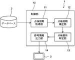
- FIG. 2 is a block diagram showing a configuration example of the server 1.
- the control unit 10 of the server 1 is a computer including a CPU (Central Processing Unit), a RAM (Random Access Memory), a ROM (Read Only Memory), a non-volatile memory, an input / output interface, and the like.
- the CPU of the control unit 10 executes information processing according to a program loaded into the RAM from the ROM or the non-volatile memory.
- the control unit 10 includes an inspection cycle acquisition unit 11, an inspection cycle correction unit 12, an inspection location specifying unit 13, and a reference information output unit 14. These functional units are realized by the CPU of the control unit 10 executing information processing according to a program loaded from the ROM or the non-volatile memory into the RAM.
- the program may be supplied via an information storage medium such as an optical disk or a memory card, or may be supplied via a communication network such as the Internet.
- FIG. 3 is a diagram showing an example of the database 2.
- Database 2 includes "delivery equipment machine information” management DB21 for each customer, "unit configuration information” management DB22 for each delivery equipment machine, “main part information” master management DB23 for each unit, and “inspection part information” master management for each unit / main part.
- DB24, "evaluation item information” master management DB25 by inspection location, “treatment content information” master management DB26 by inspection location, “inspection record information” management DB27 by delivery equipment machine / unit, and “inspection plan information” by delivery equipment machine / unit Includes management DB 28.
- the delivery equipment machine which is an industrial machine delivered to each customer, is composed of one or more units. This unit is composed of one or more major parts. One or more inspection points are defined for each of the main parts. As will be described later, various information regarding these delivered equipment machines, units, main parts and inspection points are stored in the database 2.
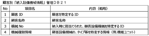
- the “delivery equipment machine information” management DB 21 for each customer is a database for managing information about the delivery equipment machine for each customer, and is a “customer ID”, “customer name”, “machine No.” and Includes “machine type information”.
- the “unit configuration information” management DB 22 for each delivered machine / equipment is a database for managing information related to the unit configuration for each delivered machine / equipment, and is a “customer ID”, “machine No.”, and “unit ID”. , "Unit name” and "Start of operation information" are included.
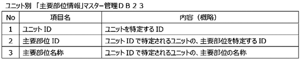
- the "main part information" master management DB23 for each unit is a database for managing information about the main part for each unit, and is a "unit ID”, "main part ID”, and "main part name”. Includes.
- the "inspection point information" master management DB24 for each unit / main part is a database for managing information about the inspection part for each main part of each unit, and is a "main part ID” and “inspection place”. Includes “ID”, "inspection location name” and "standard inspection cycle”.
- the standard inspection cycle is an inspection cycle defined for each inspection location based on the design specifications at the time of initial delivery of the equipment. This standard inspection cycle is subject to change due to post-delivery enhancements.
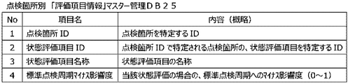
- the “evaluation item information” master management DB 25 for each inspection location is a database for managing information related to evaluation items for each inspection location, and is a database for managing information regarding evaluation items for each inspection location, such as “inspection location ID”, “state evaluation item ID”, and “state evaluation item ID”. Includes “status evaluation item name” and "standard inspection cycle negative impact”.
- condition evaluation items are condition evaluation indexes at the time of disassembly, which are set for each inspection point.
- the degree of influence on the standard inspection cycle of the inspection point (standard inspection cycle minus the degree of influence) is set.
- this influence degree value is for shortening the inspection cycle in the maintenance plan from the standard inspection cycle.
- FIG. 9 shows an example of the above state evaluation items.
- five state evaluation items are set, and the standard inspection cycle negative influence degree is set in the range of 0 to 1 for each state evaluation item.
- the state evaluation items from ID1 to ID5 are set in order from the one with the best state at the time of inspection, the standard inspection cycle of the state evaluation item of ID1 has the smallest negative influence, and the state of ID5.
- the standard inspection cycle of evaluation items has the largest negative impact. Standard inspection cycle The larger the negative impact value, that is, the poorer the condition at the time of inspection, the shorter the inspection cycle.
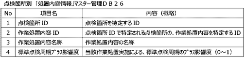
- the “treatment content information” master management DB 26 for each inspection location is a database for managing information regarding the treatment content for each inspection location, and is a database for managing information regarding the treatment content, such as “inspection location ID”, “work treatment content ID”, and “work treatment content ID”. Includes “Name of work procedure” and "Standard inspection cycle plus degree of impact”.
- the above work procedure contents are the assembly work contents after disassembly set for each inspection point.
- the degree of influence on the standard inspection cycle of the inspection point (standard inspection cycle plus degree of influence) is set.
- this degree of influence value is for extending the inspection cycle in the maintenance plan from the standard inspection cycle.
- FIG. 11 shows an example of the above work procedure contents.
- the standard inspection cycle plus the influence degree is set in the range of 0 to 1 for each work treatment content.
- the work treatment contents from ID1 to ID5 are set in order from the one with the slightest recovery mode, the standard inspection cycle plus the influence degree of the work treatment contents of ID1 is the smallest, and the state of ID5.
- the standard inspection cycle of the evaluation item plus the degree of influence is the largest. The larger the value of the standard inspection cycle plus the degree of influence, that is, the more serious the mode of restoration, the longer the inspection cycle will be.
- the “inspection record information” management DB 27 for each delivered equipment machine / unit is a database for managing information related to inspection records for each unit of each delivered equipment machine, and has “construction date” and “construction implementation date”. It includes “machine No.”, "unit ID”, “main part ID”, “inspection point ID”, “state evaluation result”, "work treatment content” and “work memorandum”.
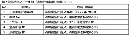
- the “inspection plan information” management DB 28 for each delivered equipment machine / unit is a database for managing information on an inspection plan (maintenance plan) for each unit of each delivered equipment machine, and is a “construction implementation plan”. Includes “year / month”, “machine No.”, “unit ID”, “main part ID” and “inspection point ID”.
- the server 1 operates in two modes: (1) normal mode and (2) inspection result reflection mode.
- the inspection points to be inspected are specified by using them as they are without correcting the standard inspection cycle defined in the database 2.
- the inspection result reflection mode the inspection points to be inspected are specified after the standard inspection cycle is corrected based on the past inspection results.
- each mode will be described separately.
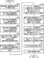
- FIG. 14 is a flowchart showing a processing procedure executed by the control unit 10 of the server 1 in the normal mode. Prior to this process, it is assumed that the terminal 3 is accessing the server 1 by an operation by the person in charge. As a result, the server 1 is in a state where it can accept the request from the terminal 3.
- control unit 10 first identifies the customer selected by the terminal 3, and then searches the customer-specific “delivery equipment machine information” management DB 21 to provide customer information (customer ID and customer). (Name) and the machine information (machine No. and machine type information) of the equipment delivered to the customer are acquired, and the acquired information is transmitted to the terminal 3 side (S101).
- the machine No. of the machine information of the equipment to be maintained is selected from the machine information received from the server 1.
- the control unit 10 searches the "unit configuration information" management DB 22 for each delivered equipment machine using the customer ID and the selected machine No. as keys, and extracts the unit configuration information of the equipment machine to be maintained (S102).
- This unit configuration information includes operation start time information (operation start date) X for each unit.
- control unit 10 searches the "main part information" master management DB 23 for each unit using the unit ID included in the extracted unit configuration information as a key, and the main part information for each unit configuration information of the equipment to be maintained. Is extracted (S103).
- control unit 10 searches the unit / main part-specific "inspection point information" master management DB 24 using the main part ID included in the extracted main part information as a key, and searches for the unit / main part of the equipment to be maintained.
- This inspection point information includes the standard inspection cycle (months) Y for each inspection point.
- the process of step S104 corresponds to the process of the inspection cycle acquisition unit 11.
- control unit 10 searches the "inspection record information" management DB 27 for each delivered equipment machine / unit using the selected machine No. as a key, and finds the latest for each unit / inspection part / inspection part of the equipment machine to be maintained.
- the inspection record information of (S105) is extracted. This inspection record information includes the construction date Z.
- control unit 10 executes the sub-process A to calculate the next inspection time candidate T (l [n, m]) for each inspection location of the unit / main part of the equipment to be maintained (S106). ..
- the content of this sub-process A will be described with reference to FIG.
- the control unit 10 first determines whether or not the latest inspection record information exists for the inspection location (S201). If it is determined that it exists here (YES in S201), the control unit 10 calculates the next inspection time candidate T (l [n, m]) by the following equation 1 (S202). On the other hand, when it is determined that it does not exist (NO in S201), the control unit 10 calculates the next inspection time candidate T (l [n, m]) by the following equation 2 (S203).
- n indicates a unit
- m indicates a main part of the unit n
- l [n, m] indicates an inspection point of the main part m of the unit n.
- X is the operation start date X extracted in step S102
- Y is the standard inspection cycle Y extracted in step S104
- Z is the construction implementation date Z extracted in step S105.
- control unit 10 has the most recent T1 and the second most recent inspection time candidate T (l [n, m]) for each inspection location of the unit / main part calculated. Extract T2 (S107).
- control unit 10 executes the sub-process B to extract the inspection points to be inspected at the time points T1 and T2 from the unit / main part-specific "inspection point information" master management DB 24 (S108).
- the content of this sub-process B will be described with reference to FIG.
- the control unit 10 first acquires the next inspection time candidate T (l [n, m]) for each inspection location of the unit / main part calculated by the sub-process A (S301), which is It is determined whether or not it is the same as the time point T1 (S302).
- step S302 If it is determined in step S302 that they are the same (YES in S302), the control unit 10 searches the "inspection location information" master management DB 24 for each unit / main portion using the inspection location ID as a key, and searches for the inspection location next time.
- the process of step S303 corresponds to the process of the inspection location specifying unit 13. If it is determined in step S302 that they are not the same (NO in S302), the process of step S303 is not executed.
- control unit 10 determines whether or not the inspection points of all the units / main parts have been processed (S304), and when it is determined that there are inspection points that have not been processed yet (NO in S304). Returning to step S301, on the other hand, if it is determined that all the inspection points have been processed (YES in S304), the process proceeds to step S305.
- control unit 10 acquires the next inspection time candidate T (l [n, m]) for each inspection location of the unit / main part (S305), and is it the same as the time point T2? It is determined whether or not (S306).
- step S306 When it is determined in step S306 that they are the same (YES in S306), the control unit 10 searches the "inspection location information" master management DB 24 for each unit / main portion using the inspection location ID as a key, and repeats the inspection locations one after another. Set as an inspection item (S307).
- the process of step S307 corresponds to the process of the inspection location specifying unit 13. If it is determined in step S306 that they are not the same (NO in S306), the process of step S307 is not executed.
- control unit 10 determines whether or not the inspection points of all the units / main parts have been processed (S308), and when it is determined that there are inspection points that have not been processed yet (NO in S308). Returning to step S305, on the other hand, if it is determined that all the inspection points have been processed (YES in S308), the sub-processing B is terminated.
- control unit 10 transmits maintenance plan reference information including information on the inspection points extracted as described above to the terminal 3 side (S109).
- the process of step S109 corresponds to the process of the reference information output unit 14.
- this maintenance plan reference information also includes information on other inspection points of the main parts related to the above-extracted inspection points, that is, inspection points of the inspection points of the main parts that were not extracted by sub-processing B. include.
- the maintenance plan reference information received from the server 1 is displayed on the display unit.
- the person in charge decides the inspection plan with reference to the maintenance plan reference information, and instructs the terminal 3 to register the inspection plan.
- the terminal 3 transmits the instruction to the server 1.
- the control unit 10 of the server 1 stores the inspection plan information in the "inspection plan information" management DB 28 for each delivered equipment machine / unit according to the instruction (S110).
- a machine type display column 41 for identifying a customer and an equipment machine, a mode display column 42 for selecting an operation mode, and a unit constituting an equipment machine to be maintained are displayed.
- a unit display column 43 for displaying the presence / absence of the next plan, a next plan display column 44 for displaying the presence / absence of the next plan, and a next-time plan display column 45 for displaying the presence / absence of the next-time plan are provided.
- the machine type display column 41 is created based on the customer-specific "delivery equipment machine information" management DB 21 or the like.
- the unit name of the unit constituting the equipment machine specified by the machine type display column 41 is displayed in the unit display column 43.
- the presence or absence of the next plan for each of these units is displayed in the next plan display column 44, and the presence or absence of the next plan is displayed in the next plan display column 45.
- the unit set as the next inspection item by step S303 in the above sub-process B is considered to have the next inspection item
- the unit set as the next inspection item by step S307 is also considered to have the next inspection item.
- the presence / absence of a black circle indicates the presence / absence of a plan.
- the person in charge selects a desired one from those that are said to have a plan in the next plan display column 44 and the next plan display column 45 with reference to the screen example (1).
- the screen example (2) shown in FIG. 18 is displayed.
- the explanation will be continued assuming that the next plan for unit A has been selected.
- the main part names of the main parts constituting the selected unit (here, unit A) are displayed.
- a main part display column 46 is provided for this purpose.
- the next plan display column 44 and the next plan display column 45 the presence or absence of a plan for those main parts is displayed.
- the main part set as the next inspection item by step S303 in the above sub-process B has the next plan
- the main part set as the next inspection item by step S307 also has the next plan.
- the person in charge selects a desired one from those that are said to have a plan in the next plan display column 44 and the next plan display column 45 with reference to the screen example (2).
- the screen example (3) shown in FIG. 19 is displayed.
- the description will be continued assuming that the main part round 6 of the unit A is selected.
- the inspection candidate display column 47 for displaying information on the inspection points that are candidates for inspection work among the inspection points of the selected main parts and the inspection
- An inspection non-candidate display column 48 is provided for displaying information on inspection points that are not candidates for work.
- These inspection candidate display columns 47 and 48 are created based on the "inspection record information" management DB 27 for each delivered equipment machine / unit.
- the screen example (3) is provided with a previous plan reference button 49 for referencing the previous inspection plan and an inspection plan registration button 50 for registering the next inspection plan.
- the inspection candidate display column 47 the inspection location name of the inspection location that is a candidate for inspection work, the inspection content last performed, the implementation time, the state evaluation result and the treatment content at that time, and the memorandum are displayed. ing. In the inspection non-candidate display column 48, similar information about inspection points that are not candidates for inspection work is displayed.
- the person in charge confirms the information regarding the inspection location displayed in the inspection candidate display column 47 with reference to the screen example (3).
- the inspection points that should be inspected by the control unit 10 based on the standard inspection cycle that is, the inspection points that are expected to be inspected in the next inspection plan are shown.
- the person in charge sets this inspection point as an inspection target in the next inspection plan unless there is a particular problem. This setting is made by pressing the inspection plan registration button 50.
- the person in charge also confirms the information on the inspection location displayed in the inspection non-candidate display column 48 by referring to the screen example (3).
- the inspection points are not supposed to be inspected based on the standard inspection cycle, the inspection points that are the same as the inspection points that should be inspected are shown.
- the person in charge determines whether or not the inspection points displayed in the inspection non-candidate display column 48 should be inspected together with the inspection points displayed in the inspection candidate display column 47. do.
- various information displayed in the inspection candidate display column 47 is utilized as reference information.
- the person in charge also sets the inspection location displayed in the inspection non-candidate display column 48 as the inspection target in the next inspection plan. This setting is made by pressing the inspection plan registration button 50.
- the person in charge presses the previous plan reference button 49 in the screen example (3) as necessary. In this case, information indicating the contents of the previous inspection plan is displayed on the display unit. The information is created based on the "inspection plan information" management DB 28 for each delivered equipment / machine / unit. The person in charge determines whether or not to set the inspection point displayed in the screen example (3) as the inspection target in the next inspection plan, referring to the contents of the previous inspection plan.
- FIG. 20 is a flowchart showing a processing procedure executed by the control unit 10 of the server 1 in the inspection result reflection mode. Since steps S401 to S407 shown in FIG. 20 are the same as steps S101 to S407 of the processing procedure in the normal mode shown in FIG. 14, the description thereof will be omitted. Hereinafter, the processing after step S408 will be described.
- the control unit 10 executes the sub-process C to calculate the next inspection time candidate T'(l [n, m]) after correction for each inspection location of the unit / main part of the equipment to be maintained (S408). ..
- the content of this sub-process C will be described with reference to FIG. 21.
- the control unit 10 first determines whether or not the latest inspection record information exists for the inspection location (S501). If it is determined that it exists here (YES in S501), the control unit 10 searches the "evaluation item information" master management DB 25 for each inspection location in the state evaluation result (state evaluation item ID) of the latest inspection record information, and standardizes it.
- the inspection cycle negative influence degree ⁇ is acquired (S502).
- control unit 10 searches the "treatment content information" master management DB 26 for each inspection location using the work procedure content (work procedure content ID) of the latest inspection record information, and acquires the standard inspection cycle plus the degree of influence ⁇ ( S503).
- the control unit 10 calculates the standard inspection cycle (number of days conversion value) Y'of the standard inspection cycle (months) Y for each inspection location by the following formula 3, and determines the two standard inspection cycle influence degrees ⁇ and ⁇ .
- the corrected standard inspection cycle (monthly conversion value) Y'''' converted to the reverse month is calculated by the following formula 5. (S504).
- This correction is a process for preventing the inspection cycle from being extended more than necessary by correcting the standard inspection cycle. For example, even if restoration is performed by replacement in the past, the inspection cycle will not be doubled, but if the above equation 4 is used as it is, the inspection cycle may be doubled. By introducing the above ⁇ , it becomes possible to set the upper limit of the extension of the inspection cycle.
- control unit 10 is the most recent T1'and the second from the calculated next inspection time candidate T'(l [n, m]) after correction for each inspection point of the unit / main part.
- the most recent T2' is extracted (S409).
- control unit 10 executes the sub-process D and extracts the inspection points to be inspected at the time points T1'and T2' from the unit / main part-specific "inspection point information" master management DB 24 (S410).
- the content of this sub-process D will be described with reference to FIG. 22.
- the control unit 10 first acquires the next inspection time candidate T (l [n, m]) for each inspection location of the unit / main part calculated by the sub-process A (S601). Next, the control unit 10 determines whether or not the time point T'1 is ahead of the time point T1 (S602).
- step S602 When it is determined in step S602 that it is not the first (NO in S602), the control unit 10 determines whether or not the acquired T (l [n, m]) is the same as the time point T'1 (S603). .. If it is determined that they are the same (YES in S603), the control unit 10 proceeds to step S605 described later.
- step S602 When it is determined in step S602 that the time point T'1 is ahead of the time point T1 (YES in S602), the control unit 10 has T (l [n, m]) equal to or higher than the time point T'1. It is determined whether it is later and equal to or earlier than the time point T1 (S604). When it is determined that the condition is satisfied (YES in S604), the control unit 10 proceeds to step S605 described later.
- step S605 the control unit 10 searches the "inspection location information" master management DB 24 for each unit / main portion using the inspection location ID as a key, and sets the inspection location as the next inspection item (S605).
- the process of step S605 corresponds to the process of the inspection location specifying unit 13. If NO is determined in step S603 or S604, the process of step S605 is not executed.
- control unit 10 determines whether or not the inspection points of all the units / main parts have been processed (S606), and if it is determined that there are inspection points that have not been processed yet (NO in S606), Returning to step S601, on the other hand, if it is determined that all the inspection points have been processed (YES in S606), the process proceeds to step S607.
- control unit 10 acquires the next inspection time candidate T (l [n, m]) for each inspection location of the unit / main part (S607), and the time point T'2 is higher than the time point T2. It is determined whether or not it is ahead (S608).
- step S608 When it is determined in step S608 that it is not the first (NO in S608), the control unit 10 determines whether or not the acquired T (l [n, m]) is the same as the time point T'2 (S609). .. If it is determined that they are the same (YES in S609), the control unit 10 proceeds to step S611 described later.
- step S608 When it is determined in step S608 that the time point T'2 is ahead of the time point T2 (YES in S608), the control unit 10 has T (l [n, m]) equal to or higher than the time point T'2. It is determined whether it is later and equal to or earlier than the time point T2 (S610). When it is determined that the condition is satisfied (YES in S610), the control unit 10 proceeds to step S611 described later.
- step S611 the control unit 10 searches the "inspection location information" master management DB 24 for each unit / main portion using the inspection location ID as a key, and sets the inspection location as an inspection item one after another (S611).
- the process of step S611 corresponds to the process of the inspection location specifying unit 13. If NO is determined in step S609 or S610, the process of step S611 is not executed.
- control unit 10 determines whether or not the inspection points of all the units / main parts have been processed (S612), and when it is determined that there are inspection points that have not been processed yet (NO in S612). Returning to step S607, if it is determined that all the inspection points have been processed (YES in S612), the sub-processing D is terminated.
- the control unit 10 transmits maintenance plan reference information including information on the inspection points extracted as described above to the terminal 3 side (S411).
- the process of step S411 corresponds to the process of the reference information output unit 14.
- this maintenance plan reference information is extracted by the sub-process D among the inspection points of the main parts related to the above-extracted inspection points, that is, the inspection points of the main parts. It also contains information about inspection points that were not done.
- the maintenance plan reference information received from the server 1 is displayed on the display unit.
- the person in charge decides the inspection plan with reference to the maintenance plan reference information, and instructs the terminal 3 to register the inspection plan.
- the terminal 3 transmits the instruction to the server 1.
- the control unit 10 of the server 1 stores the inspection plan information in the "inspection plan information" management DB 28 for each delivered equipment machine / unit according to the instruction (S412).
- the maintenance plan reference information is displayed on the display unit of the terminal 3 as in the case of the normal mode. That is, the same screens as those of the screen examples (1) to (3) shown in FIGS. 17 to 19 are displayed on the display unit. However, the mode display column 42 of the screen examples (1) and (2) indicates that the inspection result reflection mode is selected.
- the inspection points to be inspected are automatically specified based on the standard inspection cycle of the inspection points. This makes it possible to formulate an appropriate maintenance plan even when the skill level of the person in charge is low.
- the inspection location is specified based on the standard inspection cycle that is appropriately corrected according to the past inspection results, so that a more appropriate maintenance plan can be formulated.
- the person in charge can formulate an appropriate maintenance plan after considering the next inspection candidate, such as excluding the inspection points that are candidates in the next inspection plan from the inspection target of the next inspection plan. can.
- the function of the server 1 is realized by a single computer, but the function of the server 1 may be realized by, for example, a distributed system by a plurality of computers.
- the standard inspection cycle is corrected by using the negative influence degree and the positive influence degree of the standard inspection cycle, but the correction may be performed by using only one of them.
- the standard inspection cycle minus the influence degree is set using the state evaluation item, and the standard inspection cycle plus the influence degree is set using the work treatment content, but the limitation is limited to this. is not it.
- the standard inspection cycle negative impact and / or positive impact may be set using other information about past inspection results for each inspection location (time required for work, difficulty of work, etc.).
- One aspect of the maintenance plan formulation support system is a maintenance plan formulation support system for supporting the formulation of a maintenance plan for an industrial machine, and the industrial machine is composed of one or a plurality of main parts.
- One or more inspection points are defined for each of the main parts, including a plurality of units, and an inspection cycle acquisition unit that acquires inspection cycle information that defines the inspection cycle for each inspection point, and the acquired inspection cycle. Based on the information, it is provided with an inspection point specifying unit that specifies the inspection points to be inspected in the next inspection, and a reference information output section that outputs maintenance plan reference information including the specified inspection points.
- an inspection result acquisition unit that acquires inspection result information indicating past inspection results for each inspection location, and an inspection cycle that corrects the inspection cycle specified in the inspection cycle information based on the acquired inspection result information.
- a correction unit may be further provided, and the inspection location specifying unit may specify the inspection location to be inspected based on the inspection cycle after correction.
- the inspection result information includes an evaluation value of the state of each inspection point after the past inspection
- the inspection cycle correction unit is the state of each inspection point included in the inspection result information.
- the inspection cycle specified in the inspection cycle information may be shortened according to the evaluation value.
- the inspection result information includes the past work contents of each inspection point
- the inspection cycle correction unit corresponds to the past work contents of each inspection point included in the inspection result information.
- the inspection cycle specified in the inspection cycle information may be extended.
- the inspection point specifying unit specifies the inspection points to be inspected in the next inspection in addition to the next inspection
- the reference information output unit specifies the specified inspection points in the next inspection and the next inspection.
- the maintenance plan reference information shown separately may be output.
- the reference information output unit may output the maintenance plan reference information including other inspection points of the main parts related to the inspection points in addition to the inspection points to be inspected in the next inspection. good.
- One aspect of the maintenance plan formulation support method is a maintenance plan formulation support method for supporting the formulation of a maintenance plan for an industrial machine, wherein the industrial machine is composed of one or a plurality of main parts.
- One or more inspection points are defined for each of the main parts including a plurality of units, and inspection cycle information that defines the inspection cycle is acquired for each inspection point, and based on the acquired inspection cycle information, the inspection cycle information is acquired. Specify the inspection points to be inspected in the next inspection, and output the maintenance plan reference information including the specified inspection points.
Landscapes
- Engineering & Computer Science (AREA)
- Business, Economics & Management (AREA)
- General Physics & Mathematics (AREA)
- Physics & Mathematics (AREA)
- Marketing (AREA)
- Economics (AREA)
- Entrepreneurship & Innovation (AREA)
- Human Resources & Organizations (AREA)
- Automation & Control Theory (AREA)
- Operations Research (AREA)
- Quality & Reliability (AREA)
- Strategic Management (AREA)
- Tourism & Hospitality (AREA)
- General Business, Economics & Management (AREA)
- Theoretical Computer Science (AREA)
- Management, Administration, Business Operations System, And Electronic Commerce (AREA)
Abstract
Description
本実施形態にかかる保全計画策定支援システムは、生産用機械等の産業用機械の保全計画の策定を支援するためのシステムである。
本実施の形態において、保全計画策定支援システムは、1台のサーバで実現されている。図1は、そのサーバおよび接続先の構成を示す模式図である。サーバ1は、データベース2にアクセス可能である。なお、データベース2は、サーバ1の内部に設けられてもよいし、サーバ1の外部に設けられ、通信ネットワークを介してアクセスされてもよい。
図3は、データベース2の例を示す図である。データベース2は、顧客別「納入設備機械情報」管理DB21、納入設備機械別「ユニット構成情報」管理DB22、ユニット別「主要部位情報」マスター管理DB23、ユニット/主要部位別「点検箇所情報」マスター管理DB24、点検箇所別「評価項目情報」マスター管理DB25、点検箇所別「処置内容情報」マスター管理DB26、納入設備機械/ユニット別「点検記録情報」管理DB27および納入設備機械/ユニット別「点検計画情報」管理DB28を含んでいる。
次に、上述したように構成された保全計画策定支援システム(サーバ1)の動作について説明する。サーバ1は、(1)通常モードおよび(2)点検結果反映モードの2つのモードで動作する。このうち、通常モードでは、データベース2で規定された標準点検周期を補正することなくそのまま用いて、点検すべき点検箇所が特定される。他方、点検結果反映モードでは、過去の点検結果に基づいて標準点検周期が補正された上で、点検すべき点検箇所が特定される。以下、各モードに分けて説明する。
図14は、通常モードにおけるサーバ1の制御部10が実行する処理手順を示すフローチャートである。なお、この処理に先立って、担当者による操作によって端末3がサーバ1にアクセスしているものとする。これにより、サーバ1は、端末3からのリクエストを受付可能な状態にある。
式1;T(l[n,m])=Z(l[n,m])+Y(l[n,m])
式2;T(l[n,m])=X(n)+Y(l[n,m])
ただし、nは、ユニット、mは、ユニットnの主要部位、l[n,m]は、ユニットnの主要部位mの点検箇所を示している。Xは、ステップS102で抽出された稼働開始年月Xであり、Yは、ステップS104で抽出された標準点検周期Yであり、Zは、ステップS105で抽出された工事実施年月Zである。
次に、点検結果反映モードにおけるシステム1の動作について説明する。上述したとおり、点検結果反映モードでは、過去の点検結果に基づいて標準点検周期が補正された上で、点検すべき点検箇所が特定される。
式3;Y'=Y×30
式4;Y''=Y'×(1-α+β)
式5;Y'''=(Y''÷30)の整数値
式6;T’(l[n,m])=Z(l[n,m])+Y'''(l[n,m])
式7;T'(l[n,m])=X(n)+Y(l[n,m])
Claims (7)
- 産業用機械の保全計画の策定を支援するための保全計画策定支援システムであって、
前記産業用機械は、1または複数の主要部位で構成される1または複数のユニットを含み、前記主要部位ごとに1または複数の点検箇所が定められており、
前記点検箇所ごとに点検周期を規定する点検周期情報を取得する点検周期取得部と、
取得した前記点検周期情報に基づいて、次回の点検において点検すべき点検箇所を特定する点検箇所特定部と、
特定した点検箇所を含む保全計画参考情報を出力する参考情報出力部とを備える、
保全計画策定支援システム。 - 点検箇所ごとの過去の点検結果を示す点検結果情報を取得する点検結果取得部と、
取得した点検結果情報に基づいて、前記点検周期情報で規定される点検周期を補正する点検周期補正部とをさらに備え、
前記点検箇所特定部は、補正後の点検周期に基づいて、前記点検すべき点検箇所を特定する、
請求項1に記載の保全計画策定支援システム。 - 前記点検結果情報には、過去の点検後における各点検箇所の状態の評価値が含まれており、
前記点検周期補正部は、前記点検結果情報に含まれる各点検箇所の状態の評価値に応じて、前記点検周期情報で規定される点検周期を短縮する、
請求項2に記載の保全計画策定支援システム。 - 前記点検結果情報には、各点検箇所の過去の作業内容が含まれており、
前記点検周期補正部は、前記点検結果情報に含まれる各点検箇所の過去の作業内容に応じて、前記点検周期情報で規定される点検周期を延長する、
請求項2に記載の保全計画策定支援システム。 - 前記点検箇所特定部は、次回の点検に加えて、次々回の点検において点検すべき点検箇所を特定し、
前記参考情報出力部は、特定した点検箇所を次回の点検および次々回の点検の別に分けて示す前記保全計画参考情報を出力する、
請求項1に記載の保全計画策定支援システム。 - 前記参考情報出力部は、次回の点検において点検すべき点検箇所に加えて、当該点検箇所にかかる主要部位の他の点検箇所を含む前記保全計画参考情報を出力する、
請求項1に記載の保全計画策定支援システム。 - 産業用機械の保全計画の策定を支援するための保全計画策定支援方法であって、
前記産業用機械は、1または複数の主要部位で構成される1または複数のユニットを含み、前記主要部位ごとに1または複数の点検箇所が定められており、
前記点検箇所ごとに点検周期を規定する点検周期情報を取得し、
取得した前記点検周期情報に基づいて、次回の点検において点検すべき点検箇所を特定し、
特定した点検箇所を含む保全計画参考情報を出力する、
保全計画策定支援方法。
Priority Applications (1)
| Application Number | Priority Date | Filing Date | Title |
|---|---|---|---|
| SA523442119A SA523442119B1 (ar) | 2020-07-17 | 2023-01-10 | نظام لدعم صياغة خطة صيانة وطريقة لدعم صياغة خطة صيانة |
Applications Claiming Priority (2)
| Application Number | Priority Date | Filing Date | Title |
|---|---|---|---|
| JP2020122951A JP7441747B2 (ja) | 2020-07-17 | 2020-07-17 | 保全計画策定支援システム及び保全計画策定支援方法 |
| JP2020-122951 | 2020-07-17 |
Publications (1)
| Publication Number | Publication Date |
|---|---|
| WO2022014162A1 true WO2022014162A1 (ja) | 2022-01-20 |
Family
ID=79555138
Family Applications (1)
| Application Number | Title | Priority Date | Filing Date |
|---|---|---|---|
| PCT/JP2021/019547 Ceased WO2022014162A1 (ja) | 2020-07-17 | 2021-05-24 | 保全計画策定支援システムおよび保全計画策定支援方法 |
Country Status (3)
| Country | Link |
|---|---|
| JP (1) | JP7441747B2 (ja) |
| SA (1) | SA523442119B1 (ja) |
| WO (1) | WO2022014162A1 (ja) |
Citations (4)
| Publication number | Priority date | Publication date | Assignee | Title |
|---|---|---|---|---|
| JP2002244707A (ja) * | 2001-02-14 | 2002-08-30 | Okuma Corp | 機械保守管理システム及び機械保守管理方法 |
| JP2003119831A (ja) * | 2001-10-18 | 2003-04-23 | Komatsu Ltd | メンテナンス計画作成システム、メンテナンス計画作成方法、およびこの方法をコンピュータに実行させるプログラム |
| JP2009043205A (ja) * | 2007-08-13 | 2009-02-26 | Chugoku Electric Power Co Inc:The | 検査要領書作成システム |
| JP2015088045A (ja) * | 2013-10-31 | 2015-05-07 | Necフィールディング株式会社 | スケジューリング装置、スケジューリングシステム、スケジューリング方法、及びプログラム |
-
2020
- 2020-07-17 JP JP2020122951A patent/JP7441747B2/ja active Active
-
2021
- 2021-05-24 WO PCT/JP2021/019547 patent/WO2022014162A1/ja not_active Ceased
-
2023
- 2023-01-10 SA SA523442119A patent/SA523442119B1/ar unknown
Patent Citations (4)
| Publication number | Priority date | Publication date | Assignee | Title |
|---|---|---|---|---|
| JP2002244707A (ja) * | 2001-02-14 | 2002-08-30 | Okuma Corp | 機械保守管理システム及び機械保守管理方法 |
| JP2003119831A (ja) * | 2001-10-18 | 2003-04-23 | Komatsu Ltd | メンテナンス計画作成システム、メンテナンス計画作成方法、およびこの方法をコンピュータに実行させるプログラム |
| JP2009043205A (ja) * | 2007-08-13 | 2009-02-26 | Chugoku Electric Power Co Inc:The | 検査要領書作成システム |
| JP2015088045A (ja) * | 2013-10-31 | 2015-05-07 | Necフィールディング株式会社 | スケジューリング装置、スケジューリングシステム、スケジューリング方法、及びプログラム |
Also Published As
| Publication number | Publication date |
|---|---|
| JP7441747B2 (ja) | 2024-03-01 |
| JP2022019229A (ja) | 2022-01-27 |
| SA523442119B1 (ar) | 2024-11-21 |
Similar Documents
| Publication | Publication Date | Title |
|---|---|---|
| US6122622A (en) | Computer aided system for compliance with chemical control laws | |
| US7698013B2 (en) | Parts production management system and parts production management method | |
| JP6702180B2 (ja) | 保全管理装置、保全管理方法、保全管理プログラム及び記録媒体 | |
| EP2227991A1 (en) | Shelf label display control device and shelf label display control method, and electronic shelf label system | |
| JP5479598B2 (ja) | 携帯端末管理サーバ、および携帯端末管理プログラム | |
| WO2013154164A1 (ja) | スケジューリング装置、スケジューリング方法およびコンピュータプログラム | |
| US7427014B2 (en) | Shelf tag, shelf tag manufacturing system, method and program for manufacturing shelf tag and storage medium | |
| US20030069656A1 (en) | Part selection aiding system | |
| Han et al. | Production planning for hybrid remanufacturing and manufacturing system with component recovery | |
| US10528588B2 (en) | Platform system, data conversion method and computer-readable non-transitory medium | |
| US6816861B2 (en) | CAD information management system and CAD information management method | |
| JP7441747B2 (ja) | 保全計画策定支援システム及び保全計画策定支援方法 | |
| JP2004272819A (ja) | ネット販売管理装置およびネット販売支援装置並びにプログラム | |
| WO2022014163A1 (ja) | 保全業務支援システムおよび保全業務支援方法 | |
| JP2015079460A (ja) | 情報処理装置およびプログラム | |
| JP2022191601A (ja) | 保全業務支援装置、保全業務支援方法及びプログラム | |
| JP2012033139A (ja) | 製品案内システム及び方法並びにコンピュータのプログラム及び記録媒体 | |
| JP2020086862A (ja) | データ生成装置、データ生成方法、データ生成プログラム、及び記録媒体 | |
| JP4580112B2 (ja) | 部品情報管理装置および部品情報管理システム | |
| CN114118903B (zh) | 一种物料生产信息的选取方法、系统、装置及存储介质 | |
| JP7052827B2 (ja) | 配置計画装置、配置計画方法及びプログラム | |
| JP2022025192A (ja) | 管理システム、及び管理プログラム | |
| JP7584363B2 (ja) | セット品処理装置、セット品処理方法、及びセット品処理プログラム | |
| JP7489082B2 (ja) | 受注商品特定支援システム | |
| US20020059409A1 (en) | Turn-around time information management system, storage medium, and turn-around time information management method |
Legal Events
| Date | Code | Title | Description |
|---|---|---|---|
| 121 | Ep: the epo has been informed by wipo that ep was designated in this application |
Ref document number: 21841584 Country of ref document: EP Kind code of ref document: A1 |
|
| NENP | Non-entry into the national phase |
Ref country code: DE |
|
| 122 | Ep: pct application non-entry in european phase |
Ref document number: 21841584 Country of ref document: EP Kind code of ref document: A1 |
|
| WWE | Wipo information: entry into national phase |
Ref document number: 523442119 Country of ref document: SA |
|
| WWE | Wipo information: entry into national phase |
Ref document number: 523442119 Country of ref document: SA |
|
| WWG | Wipo information: grant in national office |
Ref document number: 523442119 Country of ref document: SA |