WO2022014093A1 - 通信中継装置およびコンピュータプログラムを記憶した記憶媒体 - Google Patents
通信中継装置およびコンピュータプログラムを記憶した記憶媒体 Download PDFInfo
- Publication number
- WO2022014093A1 WO2022014093A1 PCT/JP2021/009615 JP2021009615W WO2022014093A1 WO 2022014093 A1 WO2022014093 A1 WO 2022014093A1 JP 2021009615 W JP2021009615 W JP 2021009615W WO 2022014093 A1 WO2022014093 A1 WO 2022014093A1
- Authority
- WO
- WIPO (PCT)
- Prior art keywords
- unit
- mobile station
- communication
- slave
- signal
- Prior art date
- Legal status (The legal status is an assumption and is not a legal conclusion. Google has not performed a legal analysis and makes no representation as to the accuracy of the status listed.)
- Ceased
Links
Images




Classifications
-
- H—ELECTRICITY
- H04—ELECTRIC COMMUNICATION TECHNIQUE
- H04W—WIRELESS COMMUNICATION NETWORKS
- H04W16/00—Network planning, e.g. coverage or traffic planning tools; Network deployment, e.g. resource partitioning or cells structures
- H04W16/24—Cell structures
- H04W16/26—Cell enhancers or enhancement, e.g. for tunnels, building shadow
-
- H—ELECTRICITY
- H04—ELECTRIC COMMUNICATION TECHNIQUE
- H04B—TRANSMISSION
- H04B7/00—Radio transmission systems, i.e. using radiation field
- H04B7/02—Diversity systems; Multi-antenna system, i.e. transmission or reception using multiple antennas
- H04B7/04—Diversity systems; Multi-antenna system, i.e. transmission or reception using multiple antennas using two or more spaced independent antennas
- H04B7/0413—MIMO systems
-
- H—ELECTRICITY
- H04—ELECTRIC COMMUNICATION TECHNIQUE
- H04B—TRANSMISSION
- H04B7/00—Radio transmission systems, i.e. using radiation field
- H04B7/14—Relay systems
- H04B7/15—Active relay systems
- H04B7/155—Ground-based stations
-
- H—ELECTRICITY
- H04—ELECTRIC COMMUNICATION TECHNIQUE
- H04B—TRANSMISSION
- H04B7/00—Radio transmission systems, i.e. using radiation field
- H04B7/14—Relay systems
- H04B7/15—Active relay systems
- H04B7/204—Multiple access
-
- H—ELECTRICITY
- H04—ELECTRIC COMMUNICATION TECHNIQUE
- H04W—WIRELESS COMMUNICATION NETWORKS
- H04W16/00—Network planning, e.g. coverage or traffic planning tools; Network deployment, e.g. resource partitioning or cells structures
- H04W16/24—Cell structures
- H04W16/28—Cell structures using beam steering
-
- H—ELECTRICITY
- H04—ELECTRIC COMMUNICATION TECHNIQUE
- H04W—WIRELESS COMMUNICATION NETWORKS
- H04W72/00—Local resource management
- H04W72/04—Wireless resource allocation
-
- H—ELECTRICITY
- H04—ELECTRIC COMMUNICATION TECHNIQUE
- H04B—TRANSMISSION
- H04B7/00—Radio transmission systems, i.e. using radiation field
- H04B7/02—Diversity systems; Multi-antenna system, i.e. transmission or reception using multiple antennas
- H04B7/022—Site diversity; Macro-diversity
- H04B7/026—Co-operative diversity, e.g. using fixed or mobile stations as relays
-
- H—ELECTRICITY
- H04—ELECTRIC COMMUNICATION TECHNIQUE
- H04W—WIRELESS COMMUNICATION NETWORKS
- H04W88/00—Devices specially adapted for wireless communication networks, e.g. terminals, base stations or access point devices
- H04W88/02—Terminal devices
- H04W88/04—Terminal devices adapted for relaying to or from another terminal or user
-
- H—ELECTRICITY
- H04—ELECTRIC COMMUNICATION TECHNIQUE
- H04W—WIRELESS COMMUNICATION NETWORKS
- H04W88/00—Devices specially adapted for wireless communication networks, e.g. terminals, base stations or access point devices
- H04W88/08—Access point devices
- H04W88/085—Access point devices with remote components
Definitions
- An embodiment of the present invention relates to a communication relay device and a storage medium for storing a computer program.
- Beamforming is one of the technologies that attracts attention in 5G (5th generation mobile communication system). This is a function that realizes expansion of coverage and expansion of cell capacity by simultaneous communication with multiple users by coordinating multiple antenna elements on one antenna and forming a beam of radio waves in any direction. Generally, it is realized by combining with a super-multi-element antenna (Massive MIMO).
- Mass MIMO super-multi-element antenna
- the DAS system relays between the mobile station and the base station, and consists of a master unit and a plurality of distributed slave units.
- the master unit distributes the signal of one base station to a plurality of slave units, and each slave unit outputs the same downlink signal from each antenna to construct an area as one cell.
- An object to be solved by the present invention is to provide a communication relay device capable of improving the communication quality with a mobile station and a storage medium for storing a computer program.
- the communication relay device of the embodiment includes a detection unit and a control unit.
- the detection unit detects a mobile station located in the cover area formed by a plurality of slave units.
- the control unit controls the communication resources used by the slave unit for communication with the mobile station for a plurality of slave units based on the detection result of the detection unit.
- FIG. 1 is a diagram showing a mobile communication system including a communication relay system.
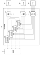
- FIG. 2 is a diagram showing a configuration example of the master unit shown in FIG.
- FIG. 3 is a diagram showing a configuration example of the UL signal processing unit shown in FIG. 2.
- FIG. 4 is a diagram showing a configuration example of the UL MUX SW shown in FIG.
- FIG. 5 is a diagram showing a configuration example of the DL signal processing unit shown in FIG.
- FIG. 6 is a diagram showing a configuration example of the DL MUX SW shown in FIG.
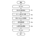
- FIG. 7 is a flowchart for explaining the processing of the master unit shown in FIG.
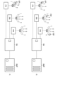
- FIG. 8 is a diagram for explaining an operation example of the distributed antenna system.
- FIG. 1 shows a part of a 5th generation mobile communication system, so-called 5G.
- This mobile communication system includes a 5G core network 5GC (5th Generation Core network) and a radio access network NR (New radio).
- 5GC 5th Generation Core network
- NR New radio
- the example of FIG. 1 shows a case where the radio access network NR includes a communication relay system.
- the 5G core network 5GC controls the radio access network NR, bundles traffic, and exchanges with an external network (Internet IN, external telephone network EN, etc.), and includes a core device C as the center thereof.
- the core device C performs, for example, authentication / security management, session management, policy control, packet transfer, and the like.
- the radio access network NR includes a plurality of base station devices (for example, gNB (gNodeB) 1 and gNB 2 in FIG. 1).
- the base station devices gNB1 and gNB2 are controlled by the core device C, and each form a wireless communication area (so-called cell) capable of communicating with the mobile station UE (User Equipment).
- the base station device gNB1 wirelessly communicates with the mobile station UE through the antenna device AN provided on the roof of the building or a dedicated steel tower, and connects the mobile station UE to the 5G core network 5GC through the core device C. .. Further, the base station device gNB1 performs beamforming by massive MIMO (Massive MIMO) that controls the phase of signals in a large number of antenna elements on the antenna device AN, and contributes to an increase in communication capacity and the like.
- massive MIMO massive MIMO
- the base station device gNB2 has the same function as the base station device gNB1, but wirelessly communicates with the mobile station UE through the distributed antenna system DAS instead of the antenna device AN, and the mobile station UE communicates wirelessly with the mobile station UE through the core device C. Connect to.
- the distributed antenna system DAS is an emergency location for the antenna device AN in special locations (for example, inside buildings, underground streets, other structures, depopulated or overcrowded areas, areas where tower construction is difficult or restricted, event venues, etc.).
- Etc. which is used to form a relatively small wireless communication area compared to the antenna device AN, and as shown in FIG. 1, the master unit MU (MasterUnit) and the slave unit RU (RemoteUnit). It is equipped with 1 to RU3 and antennas AN1 to AN3.
- the master unit MU controls each part of the distributed antenna system DAS in an integrated manner, and communicates the mobile station UE with the base station device gNB2 via the antennas (AN1 to AN3) and the slave units (RU1 to RU3). It plays a role as a communication relay device that enables it.
- the master unit MU When the master unit MU is connected to the slave units RU1 to RU3 by optical communication lines, the master unit MU may also be generally referred to as an optical repeater.
- the antennas AN1 to AN3 are connected to the corresponding slave units RU1 to RU3 on a one-to-one basis, and each consists of a large number of antenna elements, and the directivity is controlled (beamforming) by adjusting the phase of the transmitted RF signal and / or the received RF signal. ) Corresponds to Massive MIMO.
- each antenna AN1 to AN3 will be described as performing beamforming for forming a maximum of four beams in an arbitrary direction at the same time, and will be described in detail later.
- the MU will also be described as processing (relaying) up to four streams at the same time corresponding to the above four beams.
- the maximum number is not limited to 4, but may be 3 or less or 5 or more. Further, the number of beams formed by each of the antennas AN1 to AN3 is not fixed, and may be dynamically changed by varying the number of antenna elements to be used.
- the slave units RU1 to RU3 are connected to the corresponding antennas AN1 to AN3 on a one-to-one basis, and can be connected to the master unit MU via an optical communication line. Further, the slave units RU1 to RU3 can perform beamforming by phase adjustment for the corresponding antennas AN1 to AN3, respectively, and detect the direction in which the mobile station UE exists by measuring the reception intensity and beamforming. You can (search).
- the slave units RU1 to RU3 perform phase adjustment (beamforming) for each RF signal obtained by the corresponding antennas AN1 to AN3, and correspond to a maximum of four beams, respectively. To obtain the received RF signal.
- the beamforming in the slave units RU1 to RU3 out of a maximum of four beams, a beam corresponding to the number of streams assigned to each mobile station UE by the master unit MU is formed toward the mobile station UE.
- the slave units RU1 to RU3 down-convert the received RF signals corresponding to each beam and simultaneously demodulate the received RF signals corresponding to a maximum of four beams into four received signals. Then, the slave units RU1 to RU3 serially bundle the demodulated received signals, convert the electric signal into an optical signal (modulate the optical carrier wave), and transmit the demodulated signal to the master unit MU through the optical communication line.
- the stream included in the received signal is referred to as a UL stream signal.
- the slave units RU1 to RU3 convert the optical signal transmitted from the master unit MU through the optical communication line into an electric signal, and simultaneously correspond to a maximum of four streams (hereinafter, DL). Demodulate to a stream signal).
- the slave units RU1 to RU3 generate a transmission RF signal whose carrier wave is modulated by using the DL stream signal, output the transmission RF signal to the connected antennas AN1 to AN3, and radiate it into space.
- the slave units RU1 to RU3 can perform beamforming to form a maximum of four beams at the same time, and form a beam for each DL stream signal for transmission. That is, when four DL stream signals are obtained by demodulation, the slave units RU1 to RU3 form four beams, and each beam transmits one DL stream signal.
- FIG. 2 shows a configuration example of the master unit MU. That is, the master unit MU includes ports P1 to P3, a transmission unit 10, a UL (Up Link) signal processing unit 20, a DL (Down Link) signal processing unit 30, and a control unit 100.
- the ports P1 to P3 correspond to the slave units RU1 to RU3, respectively, and can be connected to the optical communication line on a one-to-one basis, and are connected to the UL signal processing unit 20 and the DL signal processing unit 30.
- Uplink Ports P1 to P3 convert optical signals sent from the corresponding slave units RU1 to RU3 into electrical signals, and demodulate up to four received signals corresponding to the beams (slave units RU1 to RU3). It is demodulated to the received signal of each beam) and output in parallel. Each demodulated received signal is output to the UL signal processing unit 20.
- the ports P1 to P3 function as an information acquisition unit that acquires information sent from the slave units RU1 to RU3 from each received signal, monitors each demodulated received signal, and is a mobile station included in the received signal. It detects a communication start request (PRACH) from the UE and detects a stream ID assigned to each received signal (UL stream signal). Further, the ports P1 to P3 function as a position detection unit, and detect the presence of the mobile station UE located in the cover area formed by the slave units RU1 to RU3 from the detection results and the like. These detection results are notified to the control unit 100.
- PRACH communication start request
- UL stream signal UL stream signal
- up to four DL stream signals are simultaneously input from the DL signal processing unit 30 to the ports P1 to P3. Then, the ports P1 to P3 serially bundle the input DL stream signals, convert the electric signal into an optical signal (modulation of the optical carrier wave), and connect the corresponding slave units RU1 to RU3 through the optical communication line. To transmit.
- the transmission unit 10 accommodates a communication line connected to the base station device gNB2, and communicates with the base station device gNB2 through this communication line. Specifically, regarding the uplink, the transmission unit 10 transmits UL signals (up to four at the same time) input from the UL signal processing unit 20 to the base station device gNB2. On the other hand, regarding the downlink, the transmission unit 10 receives DL signals (up to four at the same time) transmitted from the base station device gNB2 through the communication line and outputs them to the DL signal processing unit 30.
- the UL signal processing unit 20 performs signal addition processing for selectively adding the received signals of each beam input from ports P1 to P3 under the control of the control unit 100, and outputs the UL signal to the transmission unit 10.
- the signal addition process will be described in detail later.
- the DL signal processing unit 30 performs signal distribution processing for selectively distributing and outputting the DL signal input from the transmission unit 10 to the ports P1 to P3 under the control of the control unit 100.
- the signal distribution process will be described in detail later.
- the control unit 100 is a control center that collectively controls each unit of the master unit MU, and executes a memory (not shown) for storing a control program and control data, and processing based on the control program and the control data. It is equipped with a processor (not shown), which realizes various control functions.
- the control program may be provided by a storage medium other than the memory. The details of the control will be described in detail in the description of the operation described later.
- the UL signal processing unit 20 includes uplink multiplexer switches (UL MUX SW) 211 to 213 and addition processing units 221 to 224.
- UL MUX SW uplink multiplexer switches
- UL MUX SW211 to 213 have a one-to-one correspondence with ports P1 to P3, respectively, and up to four received signals output from ports P1 to P3 are input, and these signals are input to UL from the control unit 100. Output is selectively multiplexed according to the switching signals ⁇ , ⁇ , and ⁇ .
- the UL MUX SW211 includes a switching control unit 2110, multiplexing 2111 to 2114, and an output switch 2115.
- the multiplexed devices 2111 to 2114 each have four input terminals, and a maximum of four received signals output from the port P1 are input. Then, according to the instruction from the switching control unit 2110, the input received signal is selectively multiplexed and output to the output switch 2115 as the multiplexed reception signal.
- the output switch 2115 includes four independent switches corresponding to the multiplexing 2111 to 2114, and the multiplexing reception signal is input to each switch from the corresponding multiplexing 2111 to 2114. Then, according to the instruction from the switching control unit 2110, the multiplexed reception signal is output from the output end of the switch. This output end is the output end of UL MUX SW211.
- the switching control unit 2110 controls the multiplexing 2111 to 2114 and the output switch 2115 according to the UL switching signal ⁇ from the control unit 100, and controls multiplexing and output. That is, by the control according to the UL switching signal ⁇ , a maximum of four received signals output from the port P1 are selectively multiplexed, and the output and output destination of the multiplexed received signal are controlled.
- the addition processing units 221 to 224 each have three input ends, and are connected to one of the four output ends of UL MUX SW211 to 213, respectively, and the multiplexed reception signal is connected to the three input ends. Entered. Then, the addition processing units 221 to 224 add (synthesize) up to three multiplexed reception signals, and output the added multiplexed reception signals to the transmission unit 10 as UL signals.
- the DL signal processing unit 30 includes downlink multiplexer switches (DL MUX SW) 311 to 313.
- DL MUX SW downlink multiplexer switches
- the DL MUX SW311 to 313 have a one-to-one correspondence with the ports P1 to P3, respectively, and a maximum of four DL signals output from the transmission unit 10 are input, and these DL signals are input from the control unit 100. It is selectively multiplexed according to the switching signals ⁇ , ⁇ , and ⁇ and output to the corresponding ports P1 to P3.
- the DL MUX SW311 to 313 can also be output without multiplexing.
- the DL MUX SW311 includes a switching control unit 3110 and multiplexing units 3111 to 3114.
- the multiplexing devices 3111 to 3114 each have four input ends, and a maximum of four DL signals output from the transmission unit 10 are distributed and input to each. Then, according to the instruction from the switching control unit 2110, the multiplexing devices 3111 to 3114 selectively multiplex the input DL signal and output it as one signal. Further, the multiplexing devices 3111 to 3114 each have a one-to-one correspondence with any of the four input terminals of the port P1, and output the signal obtained by the multiplexing to the input terminal of the corresponding port P1. ..
- the switching control unit 3110 controls the multiplexing units 3111 to 3114 according to the DL switching signal ⁇ from the control unit 100, and controls multiplexing and output. That is, a maximum of four DL signals can be selectively multiplexed by the control of the switching control unit 3110 according to the DL switching signal ⁇ , and can be output to any or all of the four input ends of the port P1.
- FIG. 7 is a flowchart for explaining the control flow of the control unit 100 of the master unit MU.
- the control unit 100 executes the process shown in FIG. 7, monitors the detection results notified from the ports P1 to P3, and communicates through the slave units RU1 to RU3.
- Monitor communication start, communication in progress, communication end. That is, the control unit 100 receives a communication start request from the mobile station UE existing in the cover area formed by each slave unit RU1 to RU3, or ends the communication session performed by the mobile station UE in the same cover area. Monitor and wait for.
- the communication start request is received by the antenna AN1 and the slave unit RU1, and the port of the master unit MU is received through the optical communication line.
- the communication start request arrives at P1.
- a signal such as PRACH (Physical Random Access Channel) can be considered.
- the port P1 to which the communication start request has arrived detects the occurrence of the communication start request and notifies the control unit 100 to that effect. On the other hand, the control unit 100 recognizes that the port that has given the above notification is P1, and proceeds to step 701.
- the slave unit RU2 (or RU3) is also notified from the port P2 (or P3) by the same operation, and the control unit 100 Recognizes that there was a notification from P2 (or P3).
- the master unit MU distributes and outputs the DL signal from the base station device gNB2 to the slave units RU1 to RU3 for the downlink stream. Further, the slave units RU1 to RU3 in the initial state form a beam in the same direction according to the same algorithm and transmit the DL signal. However, as an initial setting, it is possible to make different settings for the slave units RU1 to RU3 so as to form a beam in a predetermined direction.
- step 701 the control unit 100 acquires detection results from all ports P1 to P3, counts the number of mobile station UEs in communication from the detection results for each slave unit RU1 to RU3, and proceeds to step 702.
- the ports P1 to P3 and the control unit 100 monitor the PRACH transmitted from the mobile station UE to the base station device gNB2, and the number is monitored by the mobile station.
- the UEs may be distinguished and counted for each slave unit RU1 to RU3.
- step 702 the control unit 100 executes the stream allocation process and proceeds to step 703. Specifically, the control unit 100 allocates streams ID1 to ID4 to the mobile station UE that has made the communication start request and the mobile station UE that is already communicating according to a predetermined stream allocation algorithm, and steps. Move to 703. The stream ID to be assigned to the mobile station UE during communication will be reviewed, but it may not be changed.
- the above stream allocation algorithm may consider various factors. For example, the number of streams that can be processed by the master unit MU (4 in this example) and the number of slave units accommodated by the master unit MU (this example). Then, 3 of RU1 to RU3), the number of mobile station UEs existing in the cover area of each slave unit RU1 to RU3 (for example, the number of PRACH recognized by the control unit 100), the master unit MU and each slave unit RU1.
- the stream ID to be assigned to each mobile station UE is determined based on the type of communication used by the UE, the communication capability of the mobile station UE, and the like.
- the information about the master unit MU and the slave units RU1 to RU3 may be stored in advance in the storage unit (not shown) of the master unit MU. Further, the information about the slave units RU1 to RU3 and the mobile station UE may be dynamically acquired from the slave units RU1 to RU3 and the mobile station UE by the control unit 100 through the ports P1 to P3.
- step 703 the control unit 100 notifies each slave unit RU1 to RU3 of the stream ID assigned to the mobile station UE in step 702, and proceeds to step 704. Specifically, the control unit 100 notifies each slave unit RU1 to RU3 in association with, for example, the identification information of the mobile station UE and the assigned stream ID.
- each of the handset units RU1 to RU3 that received the notification secures communication resources according to the number of stream IDs notified for each mobile station UE, and with each mobile station UE according to a predetermined procedure. Establish a communication link between them.
- step 704 the control unit 100 performs signal addition processing on the four signals output from each of the ports P1 to P3 based on the stream ID assigned to the mobile station UE in step 702, whereby the four ULs are performed. A signal is generated and the process proceeds to step 705.
- control unit 100 corresponds to the assigned stream ID among the four signals output from each of the ports P1 to P3 based on the stream ID assigned to the mobile station UE in step 702.
- the UL switching signals ⁇ , ⁇ , and ⁇ for adding signals are generated to control the signal addition processing of the UL signal processing unit 20.
- step 705 the control unit 100 controls the UL signal processing unit 20 and the transmission unit 10 to transmit the four UL signals obtained by the signal addition processing of the UL signal processing unit 20 to the base station apparatus gNB2 by the transmission unit 10. It starts to transmit and ends the process.
- control unit 100 starts the process shown in FIG. 7 again, monitors the detection result notified from the ports P1 to P3, and communicates (communication start, communication in progress, communication end) for each slave unit RU1 to RU3. To monitor.
- a communication start request is generated from the mobile station UE existing in the cover area formed by each slave unit RU1 to RU3, or when the communication session performed by the mobile station UE in the same cover area ends, the control unit 100 Again executes the processing after step 701.
- control unit 100 recognizes that the mobile station UE1 exists only in the cover area of the slave unit RU1 from the detection results of the ports P1 to P3 obtained in step 701, and uses the stream allocation algorithm of step 702. , For example, all four streams ID1 to ID4 are assigned to the slave unit RU1, and 0 streams are assigned to the remaining slave units RU2 and RU3.
- the slave unit RU1 notifies the mobile station UE1 that the streams ID1 to ID4 are assigned in step 703, secures communication resources for the four streams (UL stream signals), and performs the predetermined procedure. Therefore, a communication link for communicating with the mobile station UE1 in four streams is established. More specifically, in order to receive the four UL stream signals, the slave unit RU1 transmits all four beams that can be formed by the antenna AN1, that is, the beams corresponding to the streams ID1 to ID4 of the mobile station UE1. Form in the direction.
- the control unit 100 assigns the streams ID1 to ID4 assigned to the mobile station UE1 in step 702, so that the streams assigned to the slave unit RU1 are ID1 to ID4, and the remaining slave units RU2 and RU3. Recognizes that the number of streams assigned to is 0, and generates UL switching signals ⁇ , ⁇ , and ⁇ for adding signals corresponding to the assigned stream IDs.
- the UL switching signal ⁇ is an instruction to the UL MUX SW211 to output four signals corresponding to the four beams of the slave unit RU1 input from the port P1 to the corresponding addition processing units 221 to 224. It is a signal of.
- the UL switching signal ⁇ outputs a part or all of the four signals corresponding to the four beams of the slave unit RU2 input from the port P2 to the UL MUX SW212 to the addition processing units 221-224. It is a signal of instruction not to let.
- the UL switching signal ⁇ is input to the UL MUX SW213 from the port P3, and a part or all of the four signals corresponding to the four beams of the slave unit RU3 are added to the addition processing units 221-224. This is an instruction signal not to be output.
- the addition processing units 221 to 224 add the signals of the four streams ID1 to ID4 of the slave unit RU1 input from the port P1 with little or no signal from the other slave units RU2 and Ru3. , Each is output to the transmission unit 10. In this way, the addition processing units 221 to 224 suppress the addition of signals that are not expected to be used for communication to the signals that are actually used for communication.
- one mobile station UE (UE1, UE2, UE3) exists in each coverage area of the slave units RU1 to RU3.
- the mobile stations UE2 and UE3 have moved to the respective cover areas of the slave units RU2 and RU3 from the state shown in FIG. 7A (only the mobile station UE1 exists) (or originally, the slave units RU2) (or originally, the slave units RU2). It may be considered that the mobile stations UE2 and UE3 existing in each cover area of the RU 3 make a communication start request from a state in which communication is not performed.
- the control unit 100 has one mobile station UE (UE1, UE2, UE3) in each cover area of the slave units RU1 to RU3 from the detection results of the ports P1 to P3 obtained in step 701. Recognize that each of the three mobile stations requires communication. Then, the control unit 100 assigns, for example, two stream IDs 1 and ID 2 to the slave unit RU1 by the stream allocation algorithm of step 702, and one stream ID 3 and ID 4 to the remaining slave units RU2 and RU3, respectively. To assign.
- the reason why the number of streams allocated to the slave unit RU1 is larger than that of the slave units RU2 and RU3 is, for example, (1) when the mobile station UE1 is already communicating before the mobile stations UE2 and UE3. (2) When the mobile station UE1 is better (or worse) than the mobile station UE2 or UE3 in the wireless transmission line environment, (3) the communication type is the mobile station UE1 rather than the mobile station UE2 or UE3. If more resources are required, (4) if mobile station UE1 is a device that has priority over mobile stations UE2 and UE3 (administrator, user of special service, etc.), (5) move.
- the station UE1 is a device having higher communication performance than the mobile stations UE2 and UE3 (for example, the mobile stations UE2 and UE3 do not have the ability to use two streams). It is conceivable to weight these conditions with priority and execute the stream allocation process of step 702.
- the slave unit RU1 notifies that the mobile station UE1 is assigned the stream ID 1 and ID 2 in step 703, secures communication resources for the two streams (UL stream signals), and follows a predetermined procedure.
- a communication link for communicating with two streams is established with the mobile station UE1. More specifically, in order to receive the two UL stream signals, the slave unit RU1 has two beams out of the four beams that can be formed by the antenna AN1, that is, the beams corresponding to the streams ID1 and ID2, respectively. Is formed toward the mobile station UE1.
- the slave unit RU2 notifies that the mobile station UE2 is assigned the stream ID 3 in step 703, secures a communication resource for one stream (UL stream signal), and moves according to a predetermined procedure.
- a communication link for communicating with one stream is established with the station UE2. More specifically, in order to receive one UL stream signal, the slave unit RU2 sets one of the four beams that can be formed by the antenna AN2, that is, the beam corresponding to the stream ID 3 as a mobile station. It is formed toward the direction of UE2.
- the slave unit RU3 notifies that the mobile station UE3 is assigned the stream ID 4 in step 703, secures a communication resource for one stream (UL stream signal), and moves according to a predetermined procedure.
- a communication link for communicating with one stream is established with the station UE3. More specifically, in order to receive one UL stream signal, the slave unit RU3 sets one of the four beams that can be formed by the antenna AN3, that is, the beam corresponding to the stream ID 4, as a mobile station. It is formed toward the direction of UE3.
- the control unit 100 assigns two streams ID1 and ID2 to the mobile station UE1 in step 702, and assigns one stream ID3 and ID4 to the mobile stations UE2 and UE3, respectively. Based on this, UL switching signals ⁇ , ⁇ , and ⁇ are generated.
- the UL switching signal ⁇ adds the signals corresponding to the streams ID1 and ID2 among the four signals corresponding to the four beams of the slave unit RU1 input from the port P1 to the UL MUX SW211. This is an instruction signal to be output to the processing units 221,222.
- the UL switching signal ⁇ is always added to the UL MUX SW212 for the signal corresponding to the stream ID 3 among the four signals corresponding to the four beams of the slave unit RU2 input from the port P2.
- the remaining three signals are output to the unit 223, and some or all of them are instruction signals not to be output to the addition processing units 221 to 224.
- the UL switching signal ⁇ is always added to the UL MUX SW213 for the signal corresponding to the stream ID 4 among the four signals corresponding to the four beams of the slave unit RU3 input from the port P3.
- the remaining three signals are output to the processing unit 223, and some or all of them are instruction signals not to be output to the addition processing units 221 to 224. That is, the UL switching signals ⁇ , ⁇ , and ⁇ are signals including an instruction not to output a part or all of the signals not used for communication to the addition processing units 221 to 224.
- the addition processing units 221,222 add the signals of the two streams ID1 and ID2 of the slave unit RU1 input from the port P1 with little or no signal from the other slave units RU2 and RU3. , Each is output to the transmission unit 10.
- the addition processing unit 223 adds the signal of one stream ID 3 of the slave unit RU2 input from the port P2 to the transmission unit 10 with almost or no signal from the other slave units RU1 and RU3. Output.
- the addition processing unit 224 adds the signal of one stream ID 4 of the slave unit RU3 input from the port P3 to the transmission unit 10 with almost or no signal from the other slave units RU1 and RU2. Output. That is, the addition processing units 221 to 224 suppress the addition of signals that are not used for communication (signals for which communication is not expected) to the signals that are actually used for communication.
- the necessary stream allocation is autonomously performed for each slave unit, and each slave unit is assigned a stream. Beamforming is performed autonomously.
- the communication relay system having the above configuration, since the communication resources are allocated to each slave unit according to the existence of the mobile station, the communication resources in the distributed antenna system DAS can be efficiently used. As a result, it contributes to the improvement of communication quality.
- the received signals from the slave units RU1 to RU3 are added (synthesized) and transmitted to the base station device gNB2.
- some or all of the signals that are not used for communication are not added.
- the present invention is not limited to the above embodiment as it is, and at the implementation stage, the components can be modified and embodied within a range that does not deviate from the gist thereof. Further, various inventions can be formed by appropriately combining a plurality of components disclosed in the above embodiments. Further, for example, a configuration in which some components are deleted from all the components shown in the embodiment can be considered. Further, the components described in different embodiments may be combined as appropriate.
- the base station device gNB2 is directly connected to the distributed antenna system DAS has been described as an example, but the number of distributions is increased between the base station device gNB2 and the distributed antenna system DAS.
- a repeater for this purpose may be provided to connect a plurality of distributed antenna systems DAS to the base station device gNB2.
- the control unit 100 of the master unit MU determines the stream to be assigned to each slave unit RU1 to RU3, but the present invention is not limited to this.
- the control unit provided in the slave units RU1 to RU3 determines the number of streams used by the control unit based on the number of mobile station UEs existing in its own coverage area, the number of empty streams notified from the master unit MU, and the like. You may decide.
- the repeater described above may perform the same processing as that of the control unit 100, and the repeater may allocate a stream to each distributed antenna system DAS.
- the master unit MU distributes and outputs the DL signal from the base station device gNB2 to the slave units RU1 to RU3 for the downlink stream.
- the master unit MU selectively selects a maximum of four DL signals sent from the base station device gNB2 according to the DL switching signals ⁇ , ⁇ , and ⁇ from the control unit 100. It has a function to output to ports P1 to P3 of.
- the same number of slave units (RU1 to RU3) to which the uplink stream is assigned is referred to with reference to the result of this allocation.
- a downlink stream may be assigned so that the slave units RU1 to RU3 can transmit the downlink stream accordingly.
Landscapes
- Engineering & Computer Science (AREA)
- Computer Networks & Wireless Communication (AREA)
- Signal Processing (AREA)
- Mobile Radio Communication Systems (AREA)
- Radio Relay Systems (AREA)
Abstract
Description
図1は、第5世代移動通信システム、いわゆる5Gの一部を示すものである。この移動通信システムは、5Gコアネットワーク5GC(5th Generation Core network)と、無線アクセスネットワークNR(New radio)を備える。図1の例では、無線アクセスネットワークNRに、通信中継システムを含む場合を示している。
ポートP1~P3は、それぞれ子機RU1~RU3に対応し、1対1で光通信回線に対し接続可能とするものであるとともに、UL信号処理部20とDL信号処理部30に接続される。
UL信号処理部20は、アップリンク・マルチプレクサ・スイッチ(UL MUX SW)211~213と、加算処理部221~224とを備える。
UL MUX SW211は、切替制御部2110、多重化器2111~2114、出力用スイッチ2115を備える。
DL信号処理部30は、ダウンリンク・マルチプレクサ・スイッチ(DL MUX SW)311~313を備える。
DL MUX SW311は、切替制御部3110、多重化器3111~3114を備える。
図8(a)に示すように、子機RU1~RU3のうち、子機RU1のカバーエリアにのみ通信を求める移動局UE1が存在する場合、すなわち、移動局UE1から通信開始要求が送信され、他の子機RU2、RU3のカバーエリアには移動局が存在しない場合を考える。
この例では、子機RU1~RU3の各カバーエリアに、それぞれ1つの移動局UE(UE1、UE2、UE3)が存在する。あるいは、図7(a)に示した状態(移動局UE1のみが存在)から、子機RU2、RU3の各カバーエリアにそれぞれ移動局UE2、UE3が移動してきた場合(あるいは、もともと子機RU2、RU3の各カバーエリアにそれぞれ存在した移動局UE2、UE3が、通信を行っていない状態から通信開始要求を行った場合)と考えてもよい。
すなわち、UL切替信号α、β、γは、通信に使用されていない信号の一部または全部を加算処理部221~224に出力させない指示を含む信号である。
すなわち、加算処理部221~224では、実際に通信に利用される信号に、通信に使用されていない信号(通信が予期されていない信号)が加算されることが抑制されている。
その他、この発明の要旨を逸脱しない範囲で種々の変形を施しても同様に実施可能であることはいうまでもない。
Claims (6)
- 移動局と無線通信する複数の子機が接続可能であり、前記移動局から前記子機を通じて送信された信号を基地局に伝送する通信中継装置において、
前記子機の形成するカバーエリア内に位置する移動局を検出する検出部と、
この検出部の検出結果に基づいて、前記子機に対して、前記子機が前記移動局との通信に用いる通信リソースを制御する制御部と、
を具備した通信中継装置。 - さらに、前記子機から情報を取得する取得部を備え、
前記制御部は、前記取得部が取得した情報と、前記検出部の検出結果に基づいて、前記複数の子機に対して、前記子機が前記移動局との通信に用いる通信リソースを制御する、請求項1に記載の通信中継装置。 - 移動局と無線通信する複数の子機が接続可能であり、前記移動局から前記子機を通じて送信された信号を基地局に伝送する通信中継装置において、
前記複数の子機からそれぞれ送信される信号を受信する受信部と、
この受信部が受信した信号を加算して、前記基地局に伝送する信号を生成する加算部と、
前記受信部が受信した信号のうち、通信に使用されていない信号を前記加算部が加算しないように制御する制御部と、
を具備した通信中継装置。 - さらに、前記子機から情報を取得する取得部を備え、
前記制御部は、前記取得部が取得した情報に基づいて、前記受信部が受信した信号のうち、通信に使用されていない信号を前記加算部が加算しないように制御する、請求項3に記載の通信中継装置。 - 移動局と無線通信する複数の子機が接続可能であり、前記移動局から前記子機を通じて送信された信号を基地局に伝送する通信中継装置で用いられるコンピュータを、
前記子機の形成するカバーエリア内に位置する移動局を検出する検出部と、
この検出部の検出結果に基づいて、前記子機に対して、前記子機が前記移動局との通信に用いる通信リソースを制御する制御部と、
して機能させるコンピュータプログラムを記憶した記憶媒体。 - 移動局と無線通信する子機が複数接続可能であり、前記移動局から前記子機を通じて送信された信号を基地局に伝送する通信中継装置で用いられるコンピュータを、
複数の子機からそれぞれ送信される信号を受信する受信部と、
この受信部が受信した信号を加算して、前記基地局に伝送する信号を生成する加算部と、
前記受信部が受信した信号のうち、通信に使用されていない信号を前記加算部が加算しないように制御する制御部と、
して機能させるコンピュータプログラムを記憶した記憶媒体。
Priority Applications (2)
| Application Number | Priority Date | Filing Date | Title |
|---|---|---|---|
| GB2300508.5A GB2612220B (en) | 2020-07-13 | 2021-03-10 | Communication relay device and recording medium in which computer program is stored |
| US18/153,983 US12250031B2 (en) | 2020-07-13 | 2023-01-12 | Communication relay apparatus and storage medium storing computer program |
Applications Claiming Priority (2)
| Application Number | Priority Date | Filing Date | Title |
|---|---|---|---|
| JP2020120027A JP7630242B2 (ja) | 2020-07-13 | 2020-07-13 | 通信中継装置およびコンピュータプログラム |
| JP2020-120027 | 2020-07-13 |
Related Child Applications (1)
| Application Number | Title | Priority Date | Filing Date |
|---|---|---|---|
| US18/153,983 Continuation US12250031B2 (en) | 2020-07-13 | 2023-01-12 | Communication relay apparatus and storage medium storing computer program |
Publications (1)
| Publication Number | Publication Date |
|---|---|
| WO2022014093A1 true WO2022014093A1 (ja) | 2022-01-20 |
Family
ID=79554697
Family Applications (1)
| Application Number | Title | Priority Date | Filing Date |
|---|---|---|---|
| PCT/JP2021/009615 Ceased WO2022014093A1 (ja) | 2020-07-13 | 2021-03-10 | 通信中継装置およびコンピュータプログラムを記憶した記憶媒体 |
Country Status (4)
| Country | Link |
|---|---|
| US (1) | US12250031B2 (ja) |
| JP (2) | JP7630242B2 (ja) |
| GB (1) | GB2612220B (ja) |
| WO (1) | WO2022014093A1 (ja) |
Families Citing this family (1)
| Publication number | Priority date | Publication date | Assignee | Title |
|---|---|---|---|---|
| EP4236568B1 (en) | 2018-02-22 | 2026-05-06 | KDDI Corporation | Optimizing relayed communication when a segment is disconnected |
Citations (2)
| Publication number | Priority date | Publication date | Assignee | Title |
|---|---|---|---|---|
| JP2014500635A (ja) * | 2010-08-17 | 2014-01-09 | ダリ システムズ カンパニー リミテッド | 遠隔で再構成可能な分散型アンテナシステム及び分散型アンテナ方法 |
| JP2020077973A (ja) * | 2018-11-07 | 2020-05-21 | 日本電信電話株式会社 | 中継装置、中継方法及び中継プログラム |
Family Cites Families (11)
| Publication number | Priority date | Publication date | Assignee | Title |
|---|---|---|---|---|
| JP3940490B2 (ja) | 1998-03-13 | 2007-07-04 | 株式会社東芝 | 分散アンテナシステム |
| JP2006094157A (ja) * | 2004-09-24 | 2006-04-06 | Hitachi Kokusai Electric Inc | 光信号伝送システムの親局装置 |
| JP5445152B2 (ja) | 2010-01-14 | 2014-03-19 | 富士通株式会社 | 無線通信装置、リモート局装置、基地局装置 |
| US9374677B2 (en) * | 2010-03-01 | 2016-06-21 | Commscope Technologies Llc | System and method for location of mobile devices in confined environments |
| KR102136940B1 (ko) | 2010-09-14 | 2020-07-23 | 달리 시스템즈 씨오. 엘티디. | 원격으로 재구성가능한 분산 안테나 시스템 및 방법 |
| JP5825399B2 (ja) | 2014-06-09 | 2015-12-02 | 富士通株式会社 | 無線通信システムにおける、伝送制御方法、送信装置、及び、受信装置 |
| EP3400656B1 (en) | 2016-01-08 | 2022-07-20 | Blue Danube Systems, Inc. | Antenna mapping and diversity |
| JP6567438B2 (ja) | 2016-01-29 | 2019-08-28 | 株式会社東芝 | 通信中継システム、制御方法及びプログラム |
| US10742305B2 (en) * | 2017-04-07 | 2020-08-11 | Commscope Technologies Llc | Output muting are active repeater systems |
| US11297689B2 (en) * | 2019-05-20 | 2022-04-05 | Andrew Wireless Systems Gmbh | Systems and methods for uplink noise suppression for a distributed antenna system |
| US10693528B1 (en) * | 2019-06-14 | 2020-06-23 | Corning Reaserch & Development Corporation | Antenna array sharing in a multi-operator radio node in a communications system |
-
2020
- 2020-07-13 JP JP2020120027A patent/JP7630242B2/ja active Active
-
2021
- 2021-03-10 WO PCT/JP2021/009615 patent/WO2022014093A1/ja not_active Ceased
- 2021-03-10 GB GB2300508.5A patent/GB2612220B/en active Active
-
2023
- 2023-01-12 US US18/153,983 patent/US12250031B2/en active Active
-
2025
- 2025-01-24 JP JP2025010757A patent/JP7834904B2/ja active Active
Patent Citations (2)
| Publication number | Priority date | Publication date | Assignee | Title |
|---|---|---|---|---|
| JP2014500635A (ja) * | 2010-08-17 | 2014-01-09 | ダリ システムズ カンパニー リミテッド | 遠隔で再構成可能な分散型アンテナシステム及び分散型アンテナ方法 |
| JP2020077973A (ja) * | 2018-11-07 | 2020-05-21 | 日本電信電話株式会社 | 中継装置、中継方法及び中継プログラム |
Also Published As
| Publication number | Publication date |
|---|---|
| US20230308138A1 (en) | 2023-09-28 |
| JP7630242B2 (ja) | 2025-02-17 |
| GB2612220B (en) | 2025-09-03 |
| GB2612220A8 (en) | 2025-07-16 |
| US12250031B2 (en) | 2025-03-11 |
| GB2612220A (en) | 2023-04-26 |
| JP2022016998A (ja) | 2022-01-25 |
| JP2025061804A (ja) | 2025-04-11 |
| JP7834904B2 (ja) | 2026-03-24 |
| GB202300508D0 (en) | 2023-03-01 |
Similar Documents
| Publication | Publication Date | Title |
|---|---|---|
| KR102110455B1 (ko) | SUDA(Shared User Equipment-side Distributed Antenna, 사용자 단말기 측 공유 분산 안테나) 시스템 제어장치 | |
| KR101075964B1 (ko) | 통신 시스템에서 다중 링크 중계 장치 및 방법 | |
| TW202044909A (zh) | 基於行動設備中繼的覆蓋範圍擴展方法 | |
| KR20170045279A (ko) | Sudac, 사용자 장비, 기지국 및 sudac 시스템 | |
| US20130012224A1 (en) | Method and device for reducing interference among femtocells in an access device of a femtocell | |
| US20240107564A1 (en) | Communication relay system and radio device | |
| WO2020020319A1 (zh) | 一种拓展于5g网络的小区组网结构 | |
| WO2017204790A1 (en) | Connection establishment in a 5g radio access network | |
| JP7150315B2 (ja) | 無線通信システム、及び基地局 | |
| JP7834904B2 (ja) | 通信中継装置およびプログラム | |
| US9794040B2 (en) | Pilot signal resource allocation for a cellular MIMO system | |
| JP2013535910A (ja) | 携帯電話通信ネットワークにおける双方向通信方法および通信ネットワーク | |
| JP4177647B2 (ja) | 無線通信装置 | |
| US20200059275A1 (en) | Terminal, base station, wireless communication system, and method of acquiring channel state information | |
| KR102191368B1 (ko) | 무선 프론트홀 지원을 위한 ccc 기반 무선 액세스 네트워크 가상화 시스템 및 제어 방법 | |
| JP2008205904A (ja) | 通信装置および通信システム | |
| US12513536B2 (en) | Communication relay apparatus and storage medium storing computer program | |
| WO2024166765A1 (ja) | 通信中継システム、通信中継方法及びプログラム | |
| EP3755063B1 (en) | Wireless communication system and wireless communication method | |
| EP4044728A1 (en) | Resource allocation method and device, communication system and storage medium | |
| KR101434526B1 (ko) | 무선통신 시스템의 릴레이 중계기에서 간섭 정보를 이용한공간 다중화 장치 및 방법 | |
| KR20100018776A (ko) | 이동통신 서비스 시스템 및 방법 | |
| JP2008135865A (ja) | 通信システム、基地局、端末及び通信方法 | |
| JP2006191694A (ja) | 基地局送受信装置 |
Legal Events
| Date | Code | Title | Description |
|---|---|---|---|
| 121 | Ep: the epo has been informed by wipo that ep was designated in this application |
Ref document number: 21841191 Country of ref document: EP Kind code of ref document: A1 |
|
| ENP | Entry into the national phase |
Ref document number: 202300508 Country of ref document: GB Kind code of ref document: A Free format text: PCT FILING DATE = 20210310 |
|
| WWE | Wipo information: entry into national phase |
Ref document number: 2300508.5 Country of ref document: GB |
|
| NENP | Non-entry into the national phase |
Ref country code: DE |
|
| WWP | Wipo information: published in national office |
Ref document number: 2300508.5 Country of ref document: GB |
|
| 122 | Ep: pct application non-entry in european phase |
Ref document number: 21841191 Country of ref document: EP Kind code of ref document: A1 |
|
| WWG | Wipo information: grant in national office |
Ref document number: 2300508.5 Country of ref document: GB |