WO2022014021A1 - エンジンの吸気装置 - Google Patents
エンジンの吸気装置 Download PDFInfo
- Publication number
- WO2022014021A1 WO2022014021A1 PCT/JP2020/027724 JP2020027724W WO2022014021A1 WO 2022014021 A1 WO2022014021 A1 WO 2022014021A1 JP 2020027724 W JP2020027724 W JP 2020027724W WO 2022014021 A1 WO2022014021 A1 WO 2022014021A1
- Authority
- WO
- WIPO (PCT)
- Prior art keywords
- throttle
- engine
- throttle body
- shaft
- intake
- Prior art date
- Legal status (The legal status is an assumption and is not a legal conclusion. Google has not performed a legal analysis and makes no representation as to the accuracy of the status listed.)
- Ceased
Links
Images






Classifications
-
- F—MECHANICAL ENGINEERING; LIGHTING; HEATING; WEAPONS; BLASTING
- F02—COMBUSTION ENGINES; HOT-GAS OR COMBUSTION-PRODUCT ENGINE PLANTS
- F02D—CONTROLLING COMBUSTION ENGINES
- F02D11/00—Arrangements for, or adaptations to, non-automatic engine control initiation means, e.g. operator initiated
- F02D11/06—Arrangements for, or adaptations to, non-automatic engine control initiation means, e.g. operator initiated characterised by non-mechanical control linkages, e.g. fluid control linkages or by control linkages with power drive or assistance
- F02D11/10—Arrangements for, or adaptations to, non-automatic engine control initiation means, e.g. operator initiated characterised by non-mechanical control linkages, e.g. fluid control linkages or by control linkages with power drive or assistance of the electric type
-
- F—MECHANICAL ENGINEERING; LIGHTING; HEATING; WEAPONS; BLASTING
- F02—COMBUSTION ENGINES; HOT-GAS OR COMBUSTION-PRODUCT ENGINE PLANTS
- F02D—CONTROLLING COMBUSTION ENGINES
- F02D9/00—Controlling engines by throttling air or fuel-and-air induction conduits or exhaust conduits
- F02D9/08—Throttle valves specially adapted therefor; Arrangements of such valves in conduits
- F02D9/10—Throttle valves specially adapted therefor; Arrangements of such valves in conduits having pivotally-mounted flaps
-
- F—MECHANICAL ENGINEERING; LIGHTING; HEATING; WEAPONS; BLASTING
- F02—COMBUSTION ENGINES; HOT-GAS OR COMBUSTION-PRODUCT ENGINE PLANTS
- F02M—SUPPLYING COMBUSTION ENGINES IN GENERAL WITH COMBUSTIBLE MIXTURES OR CONSTITUENTS THEREOF
- F02M35/00—Combustion-air cleaners, air intakes, intake silencers, or induction systems specially adapted for, or arranged on, internal-combustion engines
- F02M35/02—Air cleaners
- F02M35/04—Air cleaners specially arranged with respect to engine, to intake system or specially adapted to vehicle; Mounting thereon ; Combinations with other devices
-
- F—MECHANICAL ENGINEERING; LIGHTING; HEATING; WEAPONS; BLASTING
- F02—COMBUSTION ENGINES; HOT-GAS OR COMBUSTION-PRODUCT ENGINE PLANTS
- F02M—SUPPLYING COMBUSTION ENGINES IN GENERAL WITH COMBUSTIBLE MIXTURES OR CONSTITUENTS THEREOF
- F02M35/00—Combustion-air cleaners, air intakes, intake silencers, or induction systems specially adapted for, or arranged on, internal-combustion engines
- F02M35/10—Air intakes; Induction systems
- F02M35/104—Intake manifolds
Definitions
- the present invention relates to an engine intake device.
- the intake device of this type of engine comprises a throttle body connected to the intake pipe of the engine to adjust the flow rate of intake air, and an air cleaner box connected to the throttle body to filter the intake air, for example, as described in Patent Document 1.
- an intake device that drives the valve body of the throttle body with a motor has also been proposed.
- the throttle body 102 of the intake device 101 is configured by connecting a pair of left and right throttle bodies 5 and 6 with the gear case 13 interposed therebetween, and one side portion 13a of the gear case 13 is the throttle body 102. It protrudes forward from.
- a motor 16 is fixed to the second fixed surface 15 of one side portion 13a of the gear case 13, and the driving force of the output shaft 16a is transmitted to the throttle shaft 8 via a gear train (not shown) in the gear case 13, and each valve.
- the body 9 is designed to open and close.
- the power supply connector 19 of the motor 16 is fixed to the first fixed surface 14 of the one side portion 13a, and the vehicle body side connector 21 extended from the control device (not shown) is connected to the power supply connector 19.
- an injector 22 is fixed to the rear of the outer surface of the throttle body 102 corresponding to each cylinder.
- the air cleaner box 4 has a box shape extended forward from the connection point with the throttle body 102, and the lower surface of the expanded portion is an engine facing surface facing the engine 1 located below at a predetermined interval. It is said to be 4a.
- the side on which the air cleaner box 4 is expanded is referred to as an expansion side, and the side opposite to the expanded side is referred to as a non-expansion side.
- the intake air introduced into the air cleaner box 4 from the outside is filtered by the element 28 and introduced into the cylinder of each cylinder of the engine 1 via the throttle body 102.
- the volume of the air cleaner box 4 greatly affects the engine performance, and it is desirable to set the engine facing surface 4a at a position close to the engine 1 as one of the measures for increasing the capacity.
- the engine facing surface 4a has a relief portion 30 for preventing interference with one side portion 13a of the gear case 13, a relief portion 31 for preventing interference with the motor 16, and a power supply.
- a relief portion 103 is formed to prevent interference with the connector 19.
- an intake device in addition to the intake device 101, there is also an intake device (not shown) in which the positional relationship between the motor 16 and the injector 22 is reversed with reference to the throttle body 102.
- the motor 16 and the power feeding connector 19 are arranged on the anti-expansion side of the air cleaner box 4, interference with those members 13a, 16 and 19 is prevented. It is no longer necessary to form the relief portions 30, 31, and 103 on the engine facing surface 4a.
- a member other than the intake device 101 such as a vehicle body frame, may be arranged adjacent to the air cleaner box 4, and auxiliary equipment may be mounted on the engine 1. It may be done. Therefore, in such a case, it is necessary to prevent interference with another member adjacent to the air cleaner box 4 or to prevent interference with auxiliary equipment.
- the present invention has been made to solve such a problem, and the purpose of the present invention is to extend the air cleaner box to the side with respect to the throttle body, and to drive the valve body to open and close the motor and the power supply connector.
- the intake of the engine can be arranged with the power supply connector without causing any harmful effects due to interference with surrounding members, regardless of whether the is arranged on the expansion side or the non-expansion side. Will provide the device.
- a valve body is arranged in the throttle bore and supported by a throttle shaft so as to be openable and closable, and one end of the throttle bore is connected to the intake pipe of the engine. It is connected to the throttle body and the other end of the throttle bore of the throttle body, and is expanded toward the side orthogonal to the axis of the throttle shaft to form a box shape with an engine facing surface facing the engine side, and is formed inside.
- An air cleaner box that filters the intake air from the outside through the intake flow passage and the element and guides it to the throttle bore, and a gear train that is provided adjacent to the throttle body in the axial direction of the throttle shaft and accommodates the gear train inside.
- the power supply connector is on the engine side of the other end of the throttle body in the axial direction of the throttle bore. It is characterized in that it is arranged in (claim 1).
- first fixing surface and the second fixing surface of the gear case project to the expansion side of the air cleaner box as one side portion (claim 2).
- first fixed surface and the second fixed surface of the gear case project to the side opposite to the expansion side of the air cleaner box (claim 3).
- the output shaft of the motor is located closer to the engine than the other end of the throttle body in the axial direction of the throttle bore, and the power supply connector is closer to the engine than the output shaft of the motor in the axial direction of the throttle bore. It is preferable that it is arranged in (claim 4).
- the power feeding connector is arranged on the side opposite to the engine from the axis of the throttle shaft (claim 5). As another aspect, it is preferable that the power feeding connector is arranged on the side opposite to the engine from one end of the throttle body in the axial direction of the throttle bore (claim 6).
- the power feeding connector is arranged on the side opposite to the engine axis in the axial direction of the throttle bore (claim 7). Further, the above configuration is most suitable for a mode in which the injector is fixed to one side orthogonal to the axis of the throttle shaft on the outer surface of the throttle body (claim 8).
- the air cleaner box is expanded laterally with respect to the throttle body, and the power supply connector is arranged on either the expansion side or the non-expansion side together with the motor for opening and closing the valve body. Even in this case, the power feeding connector can be arranged without causing an adverse effect due to interference with surrounding members.
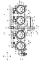
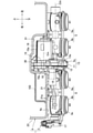
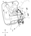
- FIG. 2 is a sectional view taken along line IV-IV of FIG. 2 showing an arrangement of a power feeding connector and an injector with respect to the throttle body.
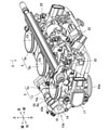
- FIG. 4 shows the relief part formed on the engine facing surface of an air cleaner box.
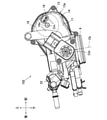
- FIG. 4 shows the throttle body of the intake device of the engine of 2nd Embodiment.
- FIG. 6 is a view taken along the line C of FIG. 6 when the throttle body is viewed from the air cleaner box side. It is a D arrow view of FIG. 7 which shows the arrangement of the power supply connector on the 1st fixed surface of a throttle body.
- FIG. 7 is a sectional view taken along line IX-IX of FIG. 7 showing an arrangement of a power feeding connector and an injector with respect to the throttle body.
- FIG. 3 which shows the arrangement of the power supply connector of the intake device of the engine of Patent Document 1.
- FIG. It is sectional drawing corresponding to FIG. 4 which shows the arrangement of the power supply connector and the injector with respect to a throttle body.
- FIG. 5 which shows the relief part formed on the engine facing surface of an air cleaner box.
- the present invention is embodied in an intake device for a four-cylinder engine mounted on a motorcycle.
- An engine is mounted on the body of a motorcycle as a power source for traveling, and an intake device is attached to the engine in the posture shown in FIG.
- the front and rear, left and right, and top and bottom are expressed with the vehicle body as the main body.
- the intake device 2 is composed of a throttle body 3 connected to the intake pipe 1a of the engine 1 to adjust the flow rate of the intake air, and an air cleaner box 4 connected to the throttle body 3 to filter the intake air.
- the throttle body 3 will be described.
- the throttle body 3 is formed by fastening the left throttle body 5 and the right throttle body 6, for example, brackets 5d extending from the throttle bodies 5 and 6 shown in FIG. It is fastened by a bolt 7 via 6d.
- the throttle bodies 5 and 6 are formed with throttle bores 5a, 5b, 6a, 6b having a substantially cylindrical shape corresponding to each cylinder of the engine 1.
- the left throttle body 5 is integrally formed with a # 1 throttle bore 5a communicating with the # 1 cylinder of the engine 1 and a # 2 throttle bore 5b communicating with the # 2 cylinder.
- the right throttle body 6 is integrally formed with a # 3 throttle bore 6a communicating with the # 3 cylinder of the engine 1 and a # 4 throttle bore 6b communicating with the # 4 cylinder.
- the throttle body 3 is arranged directly above the engine 1, and its lower end 3a is connected to the intake pipe 1a of the engine 1 by a bolt (not shown).
- each throttle bore 5a, 5b, 6a, 6b opens upward in parallel in the left-right direction, and the axis Cb forms an angle ⁇ with respect to the vertical line L, whereby the throttle body 3 Is kept tilted backwards.
- the throttle shaft 8 is rotatably supported on the left and right throttle bodies 5 and 6 through the throttle bores 5a, 5b, 6a, 6b.
- a valve body 9 is fixed to the throttle shaft 8 by a screw 10, and each valve body 9 is opened and closed as the throttle shaft 8 rotates.
- a case portion 5c having a concave shape on the right side is integrally formed at the right end of the left throttle body 5, and a case member 11 having a concave shape on the left side is interposed between the case portion 5c and the left end of the right throttle body 6. It is dressed up.
- the case portion 5c and the case member 11 are connected by a plurality of screws 12, whereby a gear case 13 is provided between the left throttle body 5 and the right throttle body 6.
- the gear case 13 has a positional relationship adjacent to the left throttle body 5 and the right throttle body 6 in the axis Cth direction of the throttle shaft 8, respectively, and one side portion 13a thereof protrudes forward.
- a first fixed surface 14 facing to the right along the axis Cth of the throttle shaft 8 and a second fixed surface 15 facing to the left along the axis Cth are formed on one side portion 13a of the gear case 13.
- a motor 16 is fixed to the second fixed surface 15, and its output shaft 16a projects into the gear case 13 along the axis Cth direction of the throttle shaft 8.
- the motor 16 is housed in a cylindrical motor housing portion 15a integrally formed on the second fixed surface 15.
- a gear train is housed in the gear case 13, and when the motor 16 is operated, the driving force of the output shaft 16a is transmitted to the throttle shaft 8 via the gear train.
- the valve body 9 is opened and closed with the rotation of the throttle shaft 8, and the flow rate of the intake air flowing through the throttle bores 5a, 5b, 6a, 6b is adjusted during the operation of the engine 1.
- the throttle opening at this time is detected by the throttle sensor 17 fixed to the left end of the right throttle body 6.
- a power supply connector 19 is fixed to the first fixed surface 14 of the gear case 13 to the right side along the axis Cth of the throttle shaft 8, in other words, to the right throttle body 6 side. It stands out.
- the power feeding connector 19 is located on the front side of the throttle bore 6a of the # 3 cylinder with its tip opened toward the right side.
- a pair of terminals 20 of the motor 16 are arranged in the gear case 13 with the output shaft 16a interposed therebetween, and although not shown, the power feeding connector 19 is electrically connected to each terminal 20 via wiring.
- the vehicle body side connector 21 extended from a control device (not shown) via the harness 21a is connected to the power supply connector 19.
- DC power is supplied from the control device to the motor 16 via the power supply connector 19 and each terminal 20 in response to the driver's throttle operation or the like, whereby the motor 16 operates and described above.
- the intake air flow rate is adjusted as described above.
- Injectors 22 are fixed behind the outer surfaces of the throttle bores 5a, 5b, 6a, 6b, respectively. During the operation of the engine 1, fuel is injected from each injector 22 into the intake air flowing through the throttle bores 5a, 5b, 6a, 6b, and is supplied as an air-fuel mixture into each cylinder of the engine 1.
- the air cleaner box 4 is composed of a box main body 23 that opens upward and a removable lid 24 that closes the opening of the box main body 23, and has a box shape as a whole.
- the air cleaner box 4 is arranged directly above the throttle body 3 and is connected to the upper end 3b of the throttle body 3 by a plurality of bolts (not shown).
- the throttle bores 5a, 5b, 6a, 6b are opened in the air cleaner box 4 and the base ends of the funnels 25 are connected to each other, and the tips of the funnels 25 are widened upward in the air cleaner box 4.
- the air cleaner box 4 is expanded forward from the position of the funnel 25, and the lower surface of the expanded portion faces the engine 1 side at a predetermined interval, and is hereinafter referred to as an engine facing surface 4a.
- the lower end 3a of the throttle body 3 corresponds to one end of the throttle body of the present invention
- the upper end 3b of the throttle body 3 corresponds to the other end of the throttle body of the present invention.
- the expansion side of the air cleaner box 4 corresponds to the other side orthogonal to the axis of the throttle shaft of the present invention
- the anti-expansion side of the air cleaner box 4 corresponds to one side orthogonal to the axis of the throttle shaft of the present invention. Equivalent to.
- intake intake ports 26 are formed on the left and right sides of the frontmost portion of the engine facing surface 4a in the air cleaner box 4, and the inside of the air cleaner box 4 communicates with the outside through each intake intake port 26.
- a partition wall 27 is erected in the vicinity of the funnel 25 on the engine facing surface 4a and extends in the left-right direction, and is between the upper end of the partition wall 27 and the leading edge of the opening of the box body 23. Is provided with an element 28 for filtration.
- the element 28 divides the inside of the air cleaner box 4 into an upstream side and a downstream side in the intake flow direction.
- an intake air flow passage 29 communicating from each intake intake port 26 to the throttle body 3 via the element 28 and the funnel 25 is formed.
- the intake negative pressure generated in the cylinder of each cylinder causes an intake flow in the air cleaner box 4 along the intake flow passage 29 as shown by an arrow in FIG. .. Therefore, the intake air introduced from each intake intake port 26 is guided upward in the air cleaner box 4 and is filtered for dust and the like when passing through the element 28, and then folded downward just below the lid 24. It is divided into each funnel 25 and introduced into the cylinder of each cylinder of the engine 1 via the throttle bores 5a, 5b, 6a, 6b of the throttle body 3.
- the present inventor paid attention to the conventional arrangement of the power feeding connector 19. Since the pair of terminals 20 connected to the power supply connector 19 are arranged so as to sandwich the output shaft 16a of the motor 16, for example, in the intake device 101 of Patent Document 1, the output shaft 16a is as shown in FIG.
- the power supply connector 19 is arranged in the vicinity of the engine, and as a result, it becomes necessary to form a relief portion 103 on the engine facing surface 4a in order to prevent interference with the power supply connector 19.
- the power supply connector 19 does not necessarily have to be arranged in the vicinity of the terminal 20, and the position of the gear case 13 on the first fixed surface 14 can be arbitrarily changed by electrically connecting to each other via wiring. Depending on the position, the relief portion 103 of the engine facing surface 4a can be eliminated.
- the engine facing surface 4a in order to increase the volume of the air cleaner box 4, it is effective to bring the engine facing surface 4a closer to the engine 1 side, that is, to position it downward, and the limit of access is the throttle bores 5a, 5b.
- the upper end 3b of the throttle body 3 serves as a rough guide in the direction of the axis Cb of 6, 6a and 6b. This is because the air cleaner box 4 is connected to the upper end 3b of the throttle body 3, so that it is difficult to set the position of the engine facing surface 4a below the air cleaner box 4. Further, if the total length of the throttle body 3 is shortened separately, the engine facing surface 4a can be brought closer to the engine 1 side by that amount.
- the power supply connector 19 is provided on the first fixed surface 14 with the upper end 3b of the throttle body 3 as the upper limit position. If arranged, it is not necessary to form the relief portion 103 for preventing interference with the engine facing surface 4a as shown by the two-dot chain line in FIG.
- the output shaft 16a of the motor 16 is located closer to the engine 1 than the upper end 3b of the throttle body 3. In that case, there is room for the engine facing surface 4a to be closer to the engine 1 side.
- the output shaft 16a of the motor 16 is located closer to the engine 1 than the upper end 3b of the throttle body 3, and the engine facing surface 4a is inclined forward and diagonally downward from the upper end 3b of the throttle body 3. ..
- the output shaft 16a of the motor 16 can be used as an index for preventing interference with the engine facing surface 4a, and as shown in the region L2 in FIG. 4, power is supplied with the axis Cm of the output shaft 16a as the upper limit position. If the connector 19 is arranged, it is not necessary to form a relief portion 103 for preventing interference with the engine facing surface 4a.
- the lower limit position of the power supply connector 19 capable of preventing interference with the engine 1 differs depending on the shape of the upper part of the engine 1.
- the upper end of the engine 1 is located below the axis Cth of the throttle shaft 8 as shown in FIG. 4, power is supplied with the axis Cth of the throttle shaft 8 as the lower limit position as shown in the region L3. If the connector 19 is provided, interference with the engine 1 can be prevented.
- the power supply connector 19 is arranged on the engine 1 side of the axis Cm of the output shaft 16a and on the side opposite to the engine 1 of the throttle shaft 8 axis Cth. ..
- the power supply connector 19 is arranged with the upper end 3b of the throttle body 3 as the upper limit position. May be good.
- the power feeding connector 19 may be arranged with the lower end 3a of the throttle body 3 as the lower limit position. Further, the position of the power feeding connector 19 may be set based only on the upper limit position without considering the lower limit position.
- a relief portion 30 for preventing interference with one side portion 13a of the gear case 13 and a relief portion 31 for preventing interference with the motor 16 are provided on the engine facing surface 4a.
- relief portions for preventing interference with the brackets 5d and 6d of the left and right throttle bodies 5 and 6 are also formed, but for preventing interference with the power feeding connector 19.
- the relief portion for example, the relief portion 103 of Patent Document 1 shown in FIG. 11 is not formed. Therefore, the volume of the air cleaner box 4 can be increased by the amount corresponding to the volume of the relief portion 103 shown by cross-hatching in FIGS. 4 and 5, and good engine performance can be realized.
- the adverse effect of the vibration of the engine 1 can be reduced. That is, the vibration of the engine 1 during operation extends to the surrounding members, but the amplitude of the vibration increases as the distance from the engine 1 which is the source of vibration increases.
- the harness 21a extends from the vehicle body side connector 21 connected to the power feeding connector 19 to the control device, but the harness 21a always shakes greatly and causes disconnection. Further, at the connection points between the connectors 19 and 21, wear progresses due to the rubbing of the contacts.
- the power supply connector 19 of the present embodiment shown in FIG. 4 is arranged at a position closer to the engine 1, and thus is transmitted from the engine 1. The amplitude of the resulting vibration is reduced. Therefore, there is an advantage that the trouble caused by the engine vibration as described above can be avoided in advance.
- the position of the power feeding connector 19 on the first fixed surface 14 of the gear case 13 is simply changed. Therefore, since it is not necessary to add a new member, it can be carried out without increasing the manufacturing cost, and since no new work is generated when the intake device 2 is assembled, it is possible to prevent the assembly work from becoming complicated. ..
- the lower end 43a of the throttle body 43 is connected to the intake pipe 1a of the engine 1, the air cleaner box 4 is connected to the upper end 43b of the throttle body 43, and the lower surface of the extension portion to the front thereof is the engine facing surface 4a. It is the same as the first embodiment. Therefore, in the present embodiment, the lower end 43a of the throttle body 43 corresponds to one end of the throttle body of the present invention, and the upper end 43b of the throttle body 43 corresponds to the other end of the throttle body of the present invention.
- the injectors 22 are fixed in front of the outer surfaces of the throttle bores 5a, 5b, 6a corresponding to the expansion side of the air cleaner box 4, respectively.
- the one side portion 13a of the gear case 13 protrudes rearward corresponding to the non-expanding side from the throttle body 43, the power supply connector 19 is fixed to the first fixed surface 14 of the one side portion 13a, and the motor is fixed to the second fixed surface 15. 16 is fixed.
- the injectors 22 of each cylinder are arranged between the engine facing surface 4a and the engine 41, and a relief portion 44 for preventing interference with the injector 22 is formed on the engine facing surface 4a.
- the expansion side of the air cleaner box 4 corresponds to one side orthogonal to the axis of the throttle shaft of the present invention
- the non-expansion side of the air cleaner box 4 corresponds to the other side orthogonal to the axis of the throttle shaft of the present invention. Equivalent to.
- one side portion 13a of the gear case 13, the motor 16 and the power feeding connector 19 are arranged behind the outer surface of the throttle body 43.
- another member 45 for example, a vehicle body frame or the like may be arranged adjacent to the air cleaner box 4 on the opposite side of these members 13a, 16 and 19 from the engine 41, that is, above. It can be considered that the lower end of the separate member 45 in such an arrangement does not extend to the throttle body 43 located below the air cleaner box 4. Therefore, as shown in the region L4 in FIG. 9, if the power feeding connector 19 is arranged with the upper end 43b of the throttle body 43 as the upper limit position, it is possible to prevent interference with another member 45 such as a vehicle body frame and the other member.
- the power supply connector 19 is separated from the 45 to form a sufficient space around it.
- an auxiliary machine 46 mounted on the engine 41 may be arranged on one side 13a of the gear case 13, the motor 16 and the engine 41 side of the power feeding connector 19, that is, below. It can be considered that the upper end of the auxiliary equipment 46 in such an arrangement does not extend to the throttle body 43 located above the engine 41. Therefore, as shown in the region L5 in FIG. 9, if the power feeding connector 19 is arranged with the lower end 43a of the throttle body 43 as the lower limit position, interference with the auxiliary equipment 46 can be prevented and the auxiliary equipment 46 can be provided. On the other hand, the power feeding connectors 19 are separated from each other to form a sufficient space around them. In the present embodiment, the lower end 43a of the throttle body 43 corresponds to the end portion of the throttle body of the present invention on the engine side.
- the upper end thereof may be located above the lower end 43a of the throttle body 43.
- the throttle shaft 8 located in the middle of the throttle body 43 is not reached, and in that case, as shown by the region L6 in FIG. 9, the axis Cth of the throttle shaft 8 is set as the lower limit position.
- the power supply connector 19 can also be arranged.
- the power supply connector 19 is arranged on the engine 41 side of the upper end 43b of the throttle body 43 and on the side opposite to the engine 41 of the axis Cth of the throttle shaft 8. .
- the connector 19 may be arranged.
- the power supply connector 19 By arranging the power supply connector 19 as described above, not only can the interference between the power supply connector 19 and the separate member 45 such as the vehicle body frame located on the upper side or the auxiliary machinery 46 or the like located on the lower side can be prevented, but also the power supply connector 19 can be prevented. Sufficient space can be secured around the. Therefore, in the assembling work of the intake device 42, the vehicle body side connector 21 can be gripped and easily connected to the power feeding connector 19, and the work efficiency can be improved.
- the intake devices 2 and 42 of the 4-cylinder engine 1 or the 3-cylinder engine 41 mounted on the motorcycle are embodied, but the application and specifications of the target engine are not limited to this.
- it may be embodied as an intake device of an engine mounted on an ATV (All Terrain Vehicle), or specifications such as the number of cylinders of the engine may be changed.
- the posture of the throttle body 3 is not limited to the posture tilted backward in the above embodiment, but may be changed to various postures.
- the power supply connector 19 on the first fixed surface 14 of the gear case 13 is opened to the right side along the axis Cth of the throttle shaft 8, but the opening direction of the power supply connector 19 is limited to this. is not it.
- the power feeding connector 19 may be opened in front of the throttle body 3 away from the throttle body 3.
Landscapes
- Engineering & Computer Science (AREA)
- Chemical & Material Sciences (AREA)
- Combustion & Propulsion (AREA)
- Mechanical Engineering (AREA)
- General Engineering & Computer Science (AREA)
- Control Of Throttle Valves Provided In The Intake System Or In The Exhaust System (AREA)
Abstract
スロットルボア(5a,5b,6a,6b)内で弁体9がスロットル軸(8)により開閉可能に支持され、一端(3a)がエンジン(1)の吸気管(1a)に連結されるスロットルボディ(3)と、スロットルボア(5a,5b,6a,6b)の他端(3b)に連結されて、スロットル軸(8)の軸線(Cth)と直交する側方に拡張されてエンジン対向面(4a)を有するエアクリーナボックス(4)と、軸線(Cth)と直交するスロットルボディ(3)の一側方に固定されたインジェクタ(22)と、ギヤ列を収容し、一側部(13a)がスロットル軸(8)の軸線(Cth)と直交する他側方に突出して第1及び第2固定面(14,15)が形成されたギヤケース(13)と、第1固定面(14)に固定された給電用コネクタ(19)と、第2固定面(15)に固定され、出力軸(16a)の駆動力をギヤ列を介してスロットル軸(8)に伝達するモータ(16)と、を備えたエンジン(1)の吸気装置(2)において、給電用コネクタ(19)が、スロットルボアの軸線(Cb)方向でスロットルボディ(3)の他端(3b)よりもエンジン(1)側に配設されている。
Description
本発明は、エンジンの吸気装置に関する。
この種のエンジンの吸気装置は、エンジンの吸気管に連結されて吸気の流量を調整するスロットルボディ、及びスロットルボディに連結されて吸気を濾過するエアクリーナボックスからなり、例えば特許文献1に記載のように、スロットルボディの弁体をモータで駆動する吸気装置も提案されている。図10~12に示すように、この吸気装置101のスロットルボディ102は、ギヤケース13を挟んで左右一対のスロットルボディ5,6を連結して構成され、ギヤケース13の一側部13aはスロットルボディ102から前方に突出している。
ギヤケース13の一側部13aの第2固定面15にはモータ16が固定され、その出力軸16aの駆動力がギヤケース13内の図示しないギヤ列を介してスロットル軸8に伝達されて、各弁体9を開閉駆動するようになっている。一側部13aの第1固定面14にはモータ16の給電用コネクタ19が固定され、給電用コネクタ19には図示しない制御装置から延設された車体側コネクタ21が接続される。また、スロットルボディ102の外側面の後方には各気筒に対応してインジェクタ22が固定されている。
一方、エアクリーナボックス4はスロットルボディ102との連結箇所から前方に拡張された箱状をなし、拡張部分の下面は、下方に位置するエンジン1に対して所定間隔をおいて相対向するエンジン対向面4aとされている。なお、以下の説明では、エアクリーナボックス4が拡張された側を拡張側と称し、それとは反対側を反拡張側と称する。エンジン1の運転中には、外部からエアクリーナボックス4内に導入された吸気がエレメント28により濾過され、スロットルボディ102を経てエンジン1の各気筒の筒内に導入される。
ところで、エアクリーナボックス4の容積はエンジン性能に大きく影響し、容量増加のための対策の一つとして、エンジン対向面4aをエンジン1に接近した位置に設定することが望ましい。しかしながら、エンジン対向面4aとエンジン1との間には、スロットルボディ102に取り付けられたギヤケース13の一側部13a、モータ16及び給電用コネクタ19が配設されている。このためエンジン対向面4aには、図11,12に示すようにギヤケース13の一側部13aとの干渉防止のための逃げ部30、モータ16との干渉防止のための逃げ部31、及び給電用コネクタ19との干渉防止のための逃げ部103が形成されている。
また上記吸気装置101とは別に、図示はしないがスロットルボディ102を基準としてモータ16とインジェクタ22との位置関係を逆転させた吸気装置も存在する。この場合には、エアクリーナボックス4の反拡張側にギヤケース13の一側部13a、モータ16及び給電用コネクタ19が配設されるため、それらの部材13a,16,19との干渉防止のための逃げ部30,31,103をエンジン対向面4aに形成する必要はなくなる。しかしながら、エアクリーナボックス4の反拡張側には、エアクリーナボックス4に隣接して吸気装置101とは別の部材、例えば車体フレーム等が配設される場合があり、またエンジン1に補機類が装着される場合もある。従って、このような場合には、エアクリーナボックス4に隣接する別部材との干渉防止、或いは補機類との干渉防止を図る必要が生じる。
以上のように、エアクリーナボックス4の拡張側と反拡張側との何れにモータ16を配設した場合でも、配設した側ではモータ16のみならず、ギヤケース13の一側部13aや給電用コネクタ19についても他の部材との干渉防止を講じる必要がある。特に給電用コネクタ19については、それ自体は小型であるものの、周囲に車体側コネクタ21を把持して接続操作できるスペースが必要である。
このため、エアクリーナボックス4の拡張側に給電用コネクタ19が配設されている場合には、エンジン対向面4aに大きな逃げ部103が形成され、結果としてエアクリーナボックス4の容積が減少してしまう上に、給電用コネクタ19を包囲する逃げ部103に妨げられて、車体側コネクタ21の接続操作が行い難くなる。また、反拡張側に給電用コネクタ19が配設されている場合には、エアクリーナボックス4に隣接する車体フレーム等の別部材やエンジン1の補機類等に妨げられて、車体側コネクタ21の接続操作が行い難くなる。従って、何れの場合も従来から抜本的な対策が要望されていた。
本発明はこのような問題点を解決するためになされたもので、その目的とするところは、スロットルボディに対してエアクリーナボックスが側方に拡張され、弁体を開閉駆動するモータと共に給電用コネクタが拡張側と反拡張側との何れに配設されている場合であっても、周囲の部材との干渉に起因する弊害を発生することなく給電用コネクタを配設することができるエンジンの吸気装置を提供することになる。
上記の目的を達成するため、本発明のエンジンの吸気装置は、スロットルボア内に弁体が配設されてスロットル軸により開閉可能に支持され、スロットルボアの一端がエンジンの吸気管に連結されるスロットルボディと、スロットルボディのスロットルボアの他端に連結されて、スロットル軸の軸線と直交する側方に向けて拡張されてエンジン側に面したエンジン対向面を有する箱状をなし、内部に形成された吸気流通路及びエレメントを経て外部からの吸気を濾過してスロットルボアに案内するエアクリーナボックスと、スロットルボディに対してスロットル軸の軸線方向に隣接して設けられて内部にギヤ列が収容され、一側部がスロットル軸の軸線と直交する他側方に突出してスロットル軸の軸線方向に面する第1固定面及び第2固定面が形成されたギヤケースと、ギヤケースの第1固定面に固定されてスロットル軸の軸線に沿ってスロットルボディ側へと突出し、制御装置からの車体側コネクタが接続される給電用コネクタと、ギヤケースの第2固定面に固定されて給電用コネクタを経た給電により作動し、出力軸の駆動力をギヤ列を介してスロットル軸に伝達するモータと、を備えたエンジンの吸気装置において、給電用コネクタが、スロットルボアの軸線方向においてスロットルボディの他端よりもエンジン側に配設されていることを特徴とする(請求項1)。
また別の態様として、ギヤケースの第1固定面及び第2固定面が、一側部としてエアクリーナボックスの拡張側に突出していることが好ましい(請求項2)。
また別の態様として、ギヤケースの第1固定面及び第2固定面が、エアクリーナボックスの拡張側とは反対側に突出していることが好ましい(請求項3)。
また別の態様として、ギヤケースの第1固定面及び第2固定面が、エアクリーナボックスの拡張側とは反対側に突出していることが好ましい(請求項3)。
また別の態様として、モータの出力軸が、スロットルボアの軸線方向においてスロットルボディの他端よりもエンジン側に位置し、給電用コネクタが、スロットルボアの軸線方向においてモータの出力軸よりもエンジン側に配設されていることが好ましい(請求項4)。
また別の態様として、給電用コネクタが、スロットル軸の軸線よりもエンジンとは反対側に配設されていることが好ましい(請求項5)。
また別の態様として、給電用コネクタが、スロットルボアの軸線方向においてスロットルボディの一端よりもエンジンとは反対側に配設されていることが好ましい(請求項6)。
また別の態様として、給電用コネクタが、スロットルボアの軸線方向においてスロットルボディの一端よりもエンジンとは反対側に配設されていることが好ましい(請求項6)。
また別の態様として、給電用コネクタが、スロットルボアの軸線方向においてスロットル軸の軸線よりもエンジンとは反対側に配設されていることが好ましい(請求項7)。
また、上記構成は、インジェクタがスロットルボディの外側面のスロットル軸の軸線と直交する一側方に固定される態様に最適である(請求項8)。
また、上記構成は、インジェクタがスロットルボディの外側面のスロットル軸の軸線と直交する一側方に固定される態様に最適である(請求項8)。
本発明のエンジンの吸気装置によれば、スロットルボディに対してエアクリーナボックスが側方に拡張され、弁体を開閉駆動するモータと共に給電用コネクタが拡張側と反拡張側との何れに配設されている場合であっても、周囲の部材との干渉に起因する弊害を発生することなく給電用コネクタを配設することができる。
[第1実施形態]
以下、本発明を自動二輪車に搭載される4気筒エンジン用の吸気装置に具体化した第1実施形態を説明する。
自動二輪車の車体には走行用動力源としてエンジンが搭載され、吸気装置は図4に示す姿勢でエンジンに取り付けられている。以下の説明では、車体を主体として前後、左右及び上下を表現する。
全体として吸気装置2は、エンジン1の吸気管1aに連結されて吸気の流量を調整するスロットルボディ3、及びスロットルボディ3に連結されて吸気を濾過するエアクリーナボックス4から構成されており、まず、スロットルボディ3について説明する。
以下、本発明を自動二輪車に搭載される4気筒エンジン用の吸気装置に具体化した第1実施形態を説明する。
自動二輪車の車体には走行用動力源としてエンジンが搭載され、吸気装置は図4に示す姿勢でエンジンに取り付けられている。以下の説明では、車体を主体として前後、左右及び上下を表現する。
全体として吸気装置2は、エンジン1の吸気管1aに連結されて吸気の流量を調整するスロットルボディ3、及びスロットルボディ3に連結されて吸気を濾過するエアクリーナボックス4から構成されており、まず、スロットルボディ3について説明する。
図1,2,4に示すように、スロットルボディ3は左側スロットルボディ5と右側スロットルボディ6とを締結してなり、例えば図1に示す各スロットルボディ5,6から延設されたブラケット5d,6dを介してボルト7により締結されている。各スロットルボディ5,6には、エンジン1の各気筒に対応して略円筒状をなすスロットルボア5a,5b,6a,6bが形成されている。
詳しくは、左側スロットルボディ5には、エンジン1の#1気筒と連通する#1スロットルボア5a及び#2気筒と連通する#2スロットルボア5bが一体形成されている。右側スロットルボディ6には、エンジン1の#3気筒と連通する#3スロットルボア6a及び#4気筒と連通する#4スロットルボア6bが一体形成されている。スロットルボディ3はエンジン1の直上に配設されて、その下端3aがエンジン1の吸気管1aに図示しないボルトで連結されている。図4に示すように、各スロットルボア5a,5b,6a,6bは左右方向に並列してそれぞれ上方に開口し、その軸線Cbが鉛直線Lに対して角度αをなすことにより、スロットルボディ3は後方に傾斜した姿勢に保たれている。
左側及び右側スロットルボディ5,6には、各スロットルボア5a,5b,6a,6bを貫通してスロットル軸8が回動可能に軸支されている。各スロットルボア5a,5b,6a,6b内においてスロットル軸8には弁体9がビス10により固定され、スロットル軸8の回動に伴って各弁体9が開閉されるようになっている。左側スロットルボディ5の右端には右側方に凹状をなすケース部5cが一体形成され、このケース部5cと右側スロットルボディ6の左端との間には、左側方に凹状をなすケース部材11が介装されている。ケース部5cとケース部材11とは複数のビス12により結合され、これにより左側スロットルボディ5及び右側スロットルボディ6の間にギヤケース13が設けられている。結果としてギヤケース13は、左側スロットルボディ5及び右側スロットルボディ6に対してそれぞれスロットル軸8の軸線Cth方向に隣接する位置関係となり、その一側部13aが前方に突出している。
ギヤケース13の一側部13aには、スロットル軸8の軸線Cthに沿って右側方に面した第1固定面14と、同じく軸線Cthに沿って左側方に面した第2固定面15とが形成されている。第2固定面15にはモータ16が固定され、その出力軸16aはスロットル軸8の軸線Cth方向に沿ってギヤケース13内に突出している。なおモータ16は、第2固定面15に一体形成された円筒状のモータ収容部15a内に収容されている。図示はしないがギヤケース13内にはギヤ列が収容され、モータ16が作動すると、出力軸16aの駆動力がギヤ列を介してスロットル軸8に伝達される。このスロットル軸8の回動に伴って弁体9が開閉され、エンジン1の運転中には各スロットルボア5a,5b,6a,6b内を流通する吸気の流量が調整される。このときのスロットル開度は、右側スロットルボディ6の左端に固定されたスロットルセンサ17により検出される。
図2,3,5に示すように、ギヤケース13の第1固定面14には給電用コネクタ19が固定されて、スロットル軸8の軸線Cthに沿って右側方、換言すると右側スロットルボディ6側へと突出している。結果として給電用コネクタ19は、その先端を右側方に向けて開口させた姿勢で#3気筒のスロットルボア6aの前側に位置している。ギヤケース13内にはモータ16の一対の端子20が出力軸16aを挟んで配設され、図示はしないが給電用コネクタ19は配線を介して各端子20と電気的に接続されている。車体への吸気装置2の搭載状態において、給電用コネクタ19には図示しない制御装置からハーネス21aを介して延設された車体側コネクタ21が接続される。エンジン1の運転中には、運転者のスロットル操作等に応じて制御装置から給電用コネクタ19及び各端子20を介してモータ16に直流電力が供給され、これによりモータ16が作動して上記のような吸気流量の調整が行われる。
各スロットルボア5a,5b,6a,6bの外側面の後方には、それぞれインジェクタ22が固定されている。エンジン1の運転中には、スロットルボア5a,5b,6a,6b内を流通する吸気中に各インジェクタ22から燃料が噴射され、混合気としてエンジン1の各筒内に供給される。
次いで、エアクリーナボックス4について説明する。
図4,5に示すようにエアクリーナボックス4は、上方に開口するボックス本体23、及びボックス本体23の開口部を閉鎖する脱着可能な蓋体24から構成され、全体として箱状をなしている。エアクリーナボックス4はスロットルボディ3の直上に配設されて、図示しない複数のボルトでスロットルボディ3の上端3bに連結されている。各スロットルボア5a,5b,6a,6bはエアクリーナボックス4内に開口してファンネル25の基端がそれぞれ連結され、各ファンネル25の先端はエアクリーナボックス4内で上方に向けて拡開している。このファンネル25の位置からエアクリーナボックス4は前方に向けて拡張され、拡張部分の下面は所定間隔をおいてエンジン1側に面しており、以下、エンジン対向面4aと称する。
本実施形態では、スロットルボディ3の下端3aが本発明のスロットルボディの一端に相当し、スロットルボディ3の上端3bが本発明のスロットルボディの他端に相当する。また本実施形態では、エアクリーナボックス4の拡張側が本発明のスロットル軸の軸線と直交する他側方に相当し、エアクリーナボックス4の反拡張側が本発明のスロットル軸の軸線と直交する一側方に相当する。
図4,5に示すようにエアクリーナボックス4は、上方に開口するボックス本体23、及びボックス本体23の開口部を閉鎖する脱着可能な蓋体24から構成され、全体として箱状をなしている。エアクリーナボックス4はスロットルボディ3の直上に配設されて、図示しない複数のボルトでスロットルボディ3の上端3bに連結されている。各スロットルボア5a,5b,6a,6bはエアクリーナボックス4内に開口してファンネル25の基端がそれぞれ連結され、各ファンネル25の先端はエアクリーナボックス4内で上方に向けて拡開している。このファンネル25の位置からエアクリーナボックス4は前方に向けて拡張され、拡張部分の下面は所定間隔をおいてエンジン1側に面しており、以下、エンジン対向面4aと称する。
本実施形態では、スロットルボディ3の下端3aが本発明のスロットルボディの一端に相当し、スロットルボディ3の上端3bが本発明のスロットルボディの他端に相当する。また本実施形態では、エアクリーナボックス4の拡張側が本発明のスロットル軸の軸線と直交する他側方に相当し、エアクリーナボックス4の反拡張側が本発明のスロットル軸の軸線と直交する一側方に相当する。
図4に示すように、エアクリーナボックス4内においてエンジン対向面4aの最前部の左右にはそれぞれ吸気導入口26が形成され、各吸気導入口26を介してエアクリーナボックス4内が外部と連通している。エアクリーナボックス4内において、エンジン対向面4a上のファンネル25の近傍には隔壁27が立設されて左右方向に延設され、この隔壁27の上端とボックス本体23の開口部の前縁との間には濾過用のエレメント28が配設されている。このエレメント28により、エアクリーナボックス4内は吸気流通方向の上流側と下流側とに区画されている。
結果としてエアクリーナボックス4内には、各吸気導入口26からエレメント28及びファンネル25を経てスロットルボディ3へと連通する吸気流通路29が形成されている。エンジン1の運転中には、各気筒の筒内で発生した吸気負圧により、エアクリーナボックス4内には図4中に矢印で示すような吸気流通路29に沿った吸気の流れが生起される。このため各吸気導入口26から導入された吸気は、エアクリーナボックス4内を上方に案内されてエレメント28を通過する際に粉塵等が濾過され、その後に蓋体24の直下で下方に折り返されて各ファンネル25に分流し、スロットルボディ3の各スロットルボア5a,5b,6a,6bを経てエンジン1の各気筒の筒内に導入される。
ところで、エアクリーナボックス4のエンジン対向面4aとエンジン1との間には、スロットルボディ3に取り付けられたギヤケース13の一側部13a、モータ16及び給電用コネクタ19等の部材が配設されているため、干渉防止のための逃げ部をエンジン対向面4aに形成する必要がある。特許文献1の吸気装置101では、これら全ての部材に対応してエンジン対向面4aに逃げ部30,31,103を形成しているため、エアクリーナボックス4の容積が大きく減少してエンジン性能に悪影響を及ぼすという問題があった。
このような不具合を鑑みて本発明者は、従来からの給電用コネクタ19の配置に着目した。給電用コネクタ19と接続される一対の端子20はモータ16の出力軸16aを挟んで配設されていることから、例えば特許文献1の吸気装置101等では、図11に示すように出力軸16aの近傍に給電用コネクタ19が配設され、結果として給電用コネクタ19との干渉防止のためにエンジン対向面4aに逃げ部103を形成する必要が生じた。しかしながら、給電用コネクタ19は必ずしも端子20の近傍に配設する必要はなく、互いに配線を介して電気的に接続することで、ギヤケース13の第1固定面14上の位置を任意に変更可能であり、その位置によってはエンジン対向面4aの逃げ部103を不要とすることができる。
一方で、エアクリーナボックス4の容積を拡大するには、そのエンジン対向面4aをエンジン1側に接近させること、即ち下方に位置させることが効果的であり、接近の限界は、スロットルボア5a,5b,6a,6bの軸線Cb方向においてスロットルボディ3の上端3bが凡その目安となる。スロットルボディ3の上端3bにエアクリーナボックス4が連結されているため、それよりも下側にエンジン対向面4aの位置を設定し難いためである。また、これとは別にスロットルボディ3の全長を短縮すれば、その分だけエンジン対向面4aをエンジン1側に接近可能となる。
そこで、スロットルボディ3の全長を短縮した上で、スロットルボア5a,5b,6a,6bの軸線Cb方向においてスロットルボディ3の上端3b付近にエンジン対向面4aの位置を設定することが、エアクリーナボックス4の容積の点で望ましい。このためスロットルボア5a,5b,6a,6bの軸線Cb方向において、図4中に領域L1で示すように、スロットルボディ3の上端3bを上限位置として第1固定面14上に給電用コネクタ19を配設すれば、図4に二点鎖線で示すようなエンジン対向面4aへの干渉防止のための逃げ部103の形成が不要となる。
また、このようにエンジン対向面4aのエンジン1への接近限界の目安はスロットルボディ3の上端3bであるものの、モータ16の出力軸16aがスロットルボディ3の上端3bよりもエンジン1側に位置する場合には、エンジン対向面4aをよりエンジン1側に接近させる余地が生まれる。例えば図4では、モータ16の出力軸16aがスロットルボディ3の上端3bよりもエンジン1側に位置しており、エンジン対向面4aはスロットルボディ3の上端3bから前方斜め下方に傾斜配置されている。モータ16の出力軸16aへの逃げ部の形成によるモータ16との干渉防止には限界があるが、図4に示すようにモータ16の約半分程度であれば逃げ部内に配設でき、結果としてエンジン対向面4aはモータ16の出力軸16aの近傍に位置する。従って、この場合にはエンジン対向面4aとの干渉防止の指標としてモータ16の出力軸16aを利用でき、図4中に領域L2で示すように、出力軸16aの軸線Cmを上限位置として給電用コネクタ19を配設すれば、エンジン対向面4aへの干渉防止のための逃げ部103の形成が不要となる。
一方、エンジン対向面4aの下方にはエンジン1が位置するため、エンジン1との干渉を防止して給電用コネクタ19を配設する必要が生じる場合もある。エンジン1との干渉防止が可能な給電用コネクタ19の下限位置は、エンジン1の上部の形状によって相違する。本実施形態では、図4に示すようにエンジン1の上端がスロットル軸8の軸線Cthよりも下方に位置しているため、領域L3で示すように、スロットル軸8の軸線Cthを下限位置として給電用コネクタ19を配設すれば、エンジン1への干渉を防止できる。
このような観点に基づき、本実施形態では出力軸16aの軸線Cmよりもエンジン1側で、且つスロットル軸8の軸線Cthよりもエンジン1とは反対側に給電用コネクタ19を配設している。但し、例えばモータ16の出力軸16aがスロットルボディ3の上端3bよりもエンジン1とは反対側に位置する場合には、スロットルボディ3の上端3bを上限位置として給電用コネクタ19を配設してもよい。また、例えばエンジン1の上端がスロットルボディ3の下端3aよりも下方に位置している場合には、スロットルボディ3の下端3aを下限位置として給電用コネクタ19を配設してもよい。さらに下限位置については考慮することなく、上限位置だけに基づき給電用コネクタ19の位置を設定してもよい。
以上の給電用コネクタ19の配置により、エアクリーナボックス4のエンジン対向面4aに逃げ部103を形成しなくても給電用コネクタ19との干渉を防止できる。結果として本実施形態では、図5に示すように、エンジン対向面4aにギヤケース13の一側部13aとの干渉防止のための逃げ部30、及びモータ16との干渉防止のための逃げ部31が形成され、さらに図示はしないが、左側及び右側スロットルボディ5,6のブラケット5d,6dとの干渉防止のための逃げ部も形成されているが、給電用コネクタ19との干渉防止のための逃げ部、例えば図11に示す特許文献1の逃げ部103等は形成されていない。従って、図4,5中にクロスハッチングで示す逃げ部103の容積に相当する分だけ、エアクリーナボックス4の容積を増加でき、良好なエンジン性能を実現することができる。
また、図11に示す特許文献1のように、エンジン対向面4aの逃げ部103内に給電用コネクタ19が配設されている場合、給電用コネクタ19を包囲する逃げ部103に妨げられて車体側コネクタ21の接続操作が行い難くなる。しかし本実施形態では、給電用コネクタ19が逃げ部103に包囲されないだけでなく、その周囲に車体側コネクタ21を把持して接続操作できる十分なスペースが形成されている。従って、車体側コネクタ21を給電用コネクタ19に容易に接続でき、その作業効率を向上できるという別の利点も得られる。
加えて、本実施形態の給電用コネクタ19の配置によれば、エンジン1の振動による悪影響を軽減できる。即ち、運転中のエンジン1の振動は周囲の部材に及ぶが、起振源であるエンジン1から離間するほど振動の振幅が増大する。例えば図5に示すように、給電用コネクタ19に接続された車体側コネクタ21からはハーネス21aが制御装置へと延設されているが、このハーネス21aが常に大きく揺れて断線の要因になる。またコネクタ19,21同士の接続箇所では、接点の擦れ合いにより摩耗が進行する。図11に示す特許文献1の給電用コネクタ19の位置に比較して、図4に示す本実施形態の給電用コネクタ19はよりエンジン1に接近した位置に配設されるため、エンジン1から伝達される振動の振幅が縮小する。従って、上記のようなエンジン振動に起因するトラブルを未然に回避できるという利点も得られる。
しかも、これらの種々の作用効果を達成するための具体的な対策としては、単にギヤケース13の第1固定面14上での給電用コネクタ19の位置を変更するだけである。従って、新たな部材の追加を要しないため製造コストアップせずに実施でき、また、吸気装置2の組付時に新たな作業が発生しないため組付作業の煩雑化を未然に防止することができる。
[第2実施形態]
次に、本発明を3気筒エンジン41に装着される別の吸気装置42に具体化した第2実施形態を説明する。
第1実施形態の吸気装置2との主要な相違点は、3気筒エンジン41への適用に伴って、スロットルボディ43の右側スロットルボディ6が#3気筒に対応する単一のスロットルボア6aを有すること、及びスロットルボディ3を基準としたモータ16とインジェクタ22との位置関係を逆転させたことにある。従って、共通する構成の箇所には同一部材番号を付して説明を省略し、相違点を重点的に説明する。
次に、本発明を3気筒エンジン41に装着される別の吸気装置42に具体化した第2実施形態を説明する。
第1実施形態の吸気装置2との主要な相違点は、3気筒エンジン41への適用に伴って、スロットルボディ43の右側スロットルボディ6が#3気筒に対応する単一のスロットルボア6aを有すること、及びスロットルボディ3を基準としたモータ16とインジェクタ22との位置関係を逆転させたことにある。従って、共通する構成の箇所には同一部材番号を付して説明を省略し、相違点を重点的に説明する。
エンジン1の吸気管1aにスロットルボディ43の下端43aが連結され、スロットルボディ43の上端43bにエアクリーナボックス4が連結され、その前方への拡張部分の下面がエンジン対向面4aとされている点は第1実施形態と同様である。従って本実施形態では、スロットルボディ43の下端43aが本発明のスロットルボディの一端に相当し、スロットルボディ43の上端43bが本発明のスロットルボディの他端に相当する。
そして本実施形態では、エアクリーナボックス4の拡張側に相当する各スロットルボア5a,5b,6aの外側面の前方に、それぞれインジェクタ22が固定されている。またギヤケース13の一側部13aは、スロットルボディ43から反拡張側に相当する後方に突出し、一側部13aの第1固定面14に給電用コネクタ19が固定され、第2固定面15にモータ16が固定されている。結果として、エンジン対向面4aとエンジン41との間には各気筒のインジェクタ22が配設され、エンジン対向面4aにはインジェクタ22との干渉を防止するための逃げ部44が形成されている。従って本実施形態では、エアクリーナボックス4の拡張側が本発明のスロットル軸の軸線と直交する一側方に相当し、エアクリーナボックス4の反拡張側が本発明のスロットル軸の軸線と直交する他側方に相当する。
そして本実施形態では、エアクリーナボックス4の拡張側に相当する各スロットルボア5a,5b,6aの外側面の前方に、それぞれインジェクタ22が固定されている。またギヤケース13の一側部13aは、スロットルボディ43から反拡張側に相当する後方に突出し、一側部13aの第1固定面14に給電用コネクタ19が固定され、第2固定面15にモータ16が固定されている。結果として、エンジン対向面4aとエンジン41との間には各気筒のインジェクタ22が配設され、エンジン対向面4aにはインジェクタ22との干渉を防止するための逃げ部44が形成されている。従って本実施形態では、エアクリーナボックス4の拡張側が本発明のスロットル軸の軸線と直交する一側方に相当し、エアクリーナボックス4の反拡張側が本発明のスロットル軸の軸線と直交する他側方に相当する。
一方、スロットルボディ43の外側面の後方には、ギヤケース13の一側部13a、モータ16及び給電用コネクタ19が配設されている。そして、これらの部材13a,16,19のエンジン41とは反対側、即ち上方にはエアクリーナボックス4に隣接して別部材45、例えば車体フレーム等が配設される場合がある。このような配置の別部材45の下端は、エアクリーナボックス4の下側に位置するスロットルボディ43までは及んでいないと見なせる。従って図9中に領域L4で示すように、スロットルボディ43の上端43bを上限位置として給電用コネクタ19を配設すれば、車体フレーム等の別部材45との干渉を防止できる上に、別部材45に対して給電用コネクタ19が離間して周囲に十分なスペースが形成される。
また、ギヤケース13の一側部13a、モータ16及び給電用コネクタ19のエンジン41側、即ち下方にはエンジン41に装着された補機類46が配設される場合がある。このような配置の補機類46の上端は、エンジン41の上側に位置するスロットルボディ43までは及んでいないと見なせる。従って図9中に領域L5で示すように、スロットルボディ43の下端43aを下限位置として給電用コネクタ19を配設すれば、補機類46との干渉を防止できる上に、補機類46に対して給電用コネクタ19が離間して周囲に十分なスペースが形成される。本実施形態では、このスロットルボディ43の下端43aが本発明のスロットルボディのエンジン側の端部に相当する。
また、補機類46の種類や取付構造によっては、その上端がスロットルボディ43の下端43aよりも上方に位置する場合もあり得る。しかし、その場合でもスロットルボディ43の中間に位置するスロットル軸8までは及んでいないと見なせ、その場合には図9中に領域L6で示すように、スロットル軸8の軸線Cthを下限位置として給電用コネクタ19を配設することもできる。
このような観点に基づき、本実施形態ではスロットルボディ43の上端43bよりもエンジン41側で、且つスロットル軸8の軸線Cthよりもエンジン41とは反対側に給電用コネクタ19を配設している。但し、例えば補機類46の上端がスロットルボディ43の下端43aよりもエンジン41側に位置している場合には、それに合わせてスロットルボディ43の下端43aよりもエンジン41とは反対側に給電用コネクタ19を配設してもよい。
以上の給電用コネクタ19の配置により、上側に位置する車体フレーム等の別部材45或いは下側に位置する補機類46等と給電用コネクタ19との干渉を防止できるばかりか、給電用コネクタ19の周囲に十分なスペースを確保できる。従って吸気装置42の組付作業では、車体側コネクタ21を把持して給電用コネクタ19に容易に接続でき、その作業効率を向上することができる。
本発明の態様はこの実施形態に限定されるものではない。上記実施形態では、自動二輪車に搭載された4気筒エンジン1または3気筒エンジン41の吸気装置2,42に具体化したが、対象となるエンジンの用途や仕様についてはこれに限るものではない。例えば、ATV(All Terrain Vehicle)に搭載されるエンジンの吸気装置として具体化してもよいし、エンジンの気筒数等の仕様を変更してもよい。またスロットルボディ3の姿勢についても、上記実施形態では後方に傾斜した姿勢としたが、これに限るものではなく、種々の姿勢に変更してもよい。
また上記実施形態では、ギヤケース13の第1固定面14上の給電用コネクタ19をスロットル軸8の軸線Cthに沿って右側方に開口させたが、給電用コネクタ19の開口方向はこれに限るものではない。例えば第1実施形態において、スロットルボディ3から離間する前方に給電用コネクタ19を開口させてもよい。
1,41 エンジン
1a,41a 吸気管
2,42 吸気装置
3,43 スロットルボディ
3a,43a 下端(一端)
3b,43b 上端(他端)
4 エアクリーナボックス
4a エンジン対向面
5a,5b,6a,6b スロットルボア
8 スロットル軸
9 弁体
13 ギヤケース
13a 一側部
14 第1固定面
15 第2固定面
16 モータ
16a 出力軸
19 給電用コネクタ
21 車体側コネクタ
22 インジェクタ
28 エレメント
29 吸気流通路
1a,41a 吸気管
2,42 吸気装置
3,43 スロットルボディ
3a,43a 下端(一端)
3b,43b 上端(他端)
4 エアクリーナボックス
4a エンジン対向面
5a,5b,6a,6b スロットルボア
8 スロットル軸
9 弁体
13 ギヤケース
13a 一側部
14 第1固定面
15 第2固定面
16 モータ
16a 出力軸
19 給電用コネクタ
21 車体側コネクタ
22 インジェクタ
28 エレメント
29 吸気流通路
Claims (8)
- スロットルボア内に弁体が配設されてスロットル軸により開閉可能に支持され、一端がエンジンの吸気管に連結されるスロットルボディと、
前記スロットルボディの他端に連結されて、前記スロットル軸の軸線と直交する側方に向けて拡張されて前記エンジン側に面したエンジン対向面を有する箱状をなし、内部に形成された吸気流通路及びエレメントを経て外部からの吸気を濾過して前記スロットルボアに案内するエアクリーナボックスと、
前記スロットルボディに対して前記スロットル軸の軸線方向に隣接して設けられて内部にギヤ列が収容され、一側部が前記スロットル軸の軸線と直交する他側方に突出して前記スロットル軸の軸線方向に面する第1固定面及び第2固定面が形成されたギヤケースと、
前記ギヤケースの第1固定面に固定されて前記スロットル軸の軸線に沿って前記スロットルボディ側へと突出し、制御装置からの車体側コネクタが接続される給電用コネクタと、 前記ギヤケースの第2固定面に固定されて前記給電用コネクタを経た給電により作動し、出力軸の駆動力を前記ギヤ列を介して前記スロットル軸に伝達するモータと、
を備えたエンジンの吸気装置において、
前記給電用コネクタは、前記スロットルボアの軸線方向において前記スロットルボディの他端よりも前記エンジン側に配設されている
ことを特徴とするエンジンの吸気装置。 - 前記ギヤケースの第1固定面及び第2固定面は、前記一側部として前記エアクリーナボックスの拡張側に突出している
ことを特徴とする請求項1に記載のエンジンの吸気装置。 - 前記ギヤケースの第1固定面及び第2固定面は、前記エアクリーナボックスの拡張側とは反対側に突出している
ことを特徴とする請求項1に記載のエンジンの吸気装置。 - 前記モータの出力軸は、前記スロットルボアの軸線方向において前記スロットルボディの他端よりも前記エンジン側に位置し、
前記給電用コネクタは、前記スロットルボアの軸線方向において前記モータの出力軸よりも前記エンジン側に配設されている
ことを特徴とする請求項2に記載のエンジンの吸気装置。 - 前記給電用コネクタは、前記スロットル軸の軸線よりも前記エンジンとは反対側に配設されている
ことを特徴とする請求項2または4に記載のエンジンの吸気装置。 - 前記給電用コネクタは、前記スロットルボアの軸線方向において前記スロットルボディの一端よりも前記エンジンとは反対側に配設されている
ことを特徴とする請求項3に記載のエンジンの吸気装置。 - 前記給電用コネクタは、前記スロットルボアの軸線方向において前記スロットル軸の軸線よりも前記エンジンとは反対側に配設されている
ことを特徴とする請求項3に記載のエンジンの吸気装置。 - 前記スロットルボディの外側面の前記スロットル軸の軸線と直交する一側方に固定され、前記スロットルボア内に燃料を噴射するインジェクタを有する
ことを特徴とする請求項1乃至7の何れか1項に記載のエンジンの吸気装置。
Priority Applications (2)
| Application Number | Priority Date | Filing Date | Title |
|---|---|---|---|
| PCT/JP2020/027724 WO2022014021A1 (ja) | 2020-07-16 | 2020-07-16 | エンジンの吸気装置 |
| JP2022536077A JPWO2022014021A1 (ja) | 2020-07-16 | 2020-07-16 |
Applications Claiming Priority (1)
| Application Number | Priority Date | Filing Date | Title |
|---|---|---|---|
| PCT/JP2020/027724 WO2022014021A1 (ja) | 2020-07-16 | 2020-07-16 | エンジンの吸気装置 |
Publications (1)
| Publication Number | Publication Date |
|---|---|
| WO2022014021A1 true WO2022014021A1 (ja) | 2022-01-20 |
Family
ID=79554590
Family Applications (1)
| Application Number | Title | Priority Date | Filing Date |
|---|---|---|---|
| PCT/JP2020/027724 Ceased WO2022014021A1 (ja) | 2020-07-16 | 2020-07-16 | エンジンの吸気装置 |
Country Status (2)
| Country | Link |
|---|---|
| JP (1) | JPWO2022014021A1 (ja) |
| WO (1) | WO2022014021A1 (ja) |
Citations (2)
| Publication number | Priority date | Publication date | Assignee | Title |
|---|---|---|---|---|
| JP2010007535A (ja) * | 2008-06-26 | 2010-01-14 | Honda Motor Co Ltd | スロットル弁装置を備える内燃機関 |
| JP2019056323A (ja) * | 2017-09-21 | 2019-04-11 | スズキ株式会社 | 内燃機関の吸気系統 |
Family Cites Families (3)
| Publication number | Priority date | Publication date | Assignee | Title |
|---|---|---|---|---|
| JP5419758B2 (ja) * | 2010-03-10 | 2014-02-19 | 本田技研工業株式会社 | 自動二輪車の吸気装置 |
| WO2018061183A1 (ja) * | 2016-09-30 | 2018-04-05 | 本田技研工業株式会社 | 車両用内燃機関の吸気部品取付け構造 |
| JP6673994B2 (ja) * | 2018-08-24 | 2020-04-01 | 本田技研工業株式会社 | エンジン |
-
2020
- 2020-07-16 WO PCT/JP2020/027724 patent/WO2022014021A1/ja not_active Ceased
- 2020-07-16 JP JP2022536077A patent/JPWO2022014021A1/ja active Pending
Patent Citations (2)
| Publication number | Priority date | Publication date | Assignee | Title |
|---|---|---|---|---|
| JP2010007535A (ja) * | 2008-06-26 | 2010-01-14 | Honda Motor Co Ltd | スロットル弁装置を備える内燃機関 |
| JP2019056323A (ja) * | 2017-09-21 | 2019-04-11 | スズキ株式会社 | 内燃機関の吸気系統 |
Also Published As
| Publication number | Publication date |
|---|---|
| JPWO2022014021A1 (ja) | 2022-01-20 |
Similar Documents
| Publication | Publication Date | Title |
|---|---|---|
| US7066135B2 (en) | Intake system for a vehicle engine | |
| US9284927B2 (en) | Motorcycle with turbocharger | |
| US7100575B2 (en) | Engine fuel injection apparatus | |
| CA2673402C (en) | Intake structure of vehicle | |
| US7219657B2 (en) | Fuel routing structure for a V-type engine | |
| WO2011077898A1 (ja) | 過給機付き自動二輪車 | |
| EP1992812B1 (en) | Motorcycle | |
| JP4609911B2 (ja) | 自動二輪車のエンジンのスロットル制御装置 | |
| JP4544603B2 (ja) | 自動二輪車のエンジンのスロットル制御装置 | |
| JPH04269372A (ja) | 自動二輪車用4サイクルエンジンの吸気装置 | |
| EP1681459B1 (en) | Fuel supply device, vehicle, and fuel supply device assembling method | |
| US20190085799A1 (en) | Intake system of internal combustion engine | |
| EP2530285B1 (en) | Intake structure of motorcycle | |
| US8042521B2 (en) | Engine unit and vehicle provided with the same | |
| JP4351584B2 (ja) | 自動二輪車の吸気装置 | |
| JP5380337B2 (ja) | 小型車両におけるスロットルボディへの配線構造 | |
| US5887673A (en) | Motorcycle | |
| JP4753745B2 (ja) | 自動二輪車の吸気構造 | |
| JP6865078B2 (ja) | 内燃機関のシリンダヘッド | |
| JP3940144B2 (ja) | 自動二輪車の燃料系配置構造 | |
| JP2917043B2 (ja) | エンジンの吸気装置 | |
| JP5513943B2 (ja) | パワーユニットの吸気系構造 | |
| JP5004098B2 (ja) | 鞍乗り型車両の吸気構造 | |
| JP2006096311A (ja) | 自動二輪車のエアクリーナ | |
| US11002232B2 (en) | V-engine air intake structure |
Legal Events
| Date | Code | Title | Description |
|---|---|---|---|
| 121 | Ep: the epo has been informed by wipo that ep was designated in this application |
Ref document number: 20945051 Country of ref document: EP Kind code of ref document: A1 |
|
| ENP | Entry into the national phase |
Ref document number: 2022536077 Country of ref document: JP Kind code of ref document: A |
|
| NENP | Non-entry into the national phase |
Ref country code: DE |
|
| 122 | Ep: pct application non-entry in european phase |
Ref document number: 20945051 Country of ref document: EP Kind code of ref document: A1 |