WO2022013916A1 - 送信側伝送装置、受信側伝送装置、送信側伝送装置の冗長化方法、受信側伝送装置の冗長化方法、プログラム、及び伝送装置 - Google Patents
送信側伝送装置、受信側伝送装置、送信側伝送装置の冗長化方法、受信側伝送装置の冗長化方法、プログラム、及び伝送装置 Download PDFInfo
- Publication number
- WO2022013916A1 WO2022013916A1 PCT/JP2020/027249 JP2020027249W WO2022013916A1 WO 2022013916 A1 WO2022013916 A1 WO 2022013916A1 JP 2020027249 W JP2020027249 W JP 2020027249W WO 2022013916 A1 WO2022013916 A1 WO 2022013916A1
- Authority
- WO
- WIPO (PCT)
- Prior art keywords
- transmitter
- signal
- receiver
- input
- switch
- Prior art date
- Legal status (The legal status is an assumption and is not a legal conclusion. Google has not performed a legal analysis and makes no representation as to the accuracy of the status listed.)
- Ceased
Links
Images





Classifications
-
- H—ELECTRICITY
- H04—ELECTRIC COMMUNICATION TECHNIQUE
- H04L—TRANSMISSION OF DIGITAL INFORMATION, e.g. TELEGRAPHIC COMMUNICATION
- H04L1/00—Arrangements for detecting or preventing errors in the information received
- H04L1/22—Arrangements for detecting or preventing errors in the information received using redundant apparatus to increase reliability
-
- G—PHYSICS
- G06—COMPUTING OR CALCULATING; COUNTING
- G06F—ELECTRIC DIGITAL DATA PROCESSING
- G06F11/00—Error detection; Error correction; Monitoring
- G06F11/07—Responding to the occurrence of a fault, e.g. fault tolerance
- G06F11/14—Error detection or correction of the data by redundancy in operations
- G06F11/1402—Saving, restoring, recovering or retrying
- G06F11/1415—Saving, restoring, recovering or retrying at system level
- G06F11/142—Reconfiguring to eliminate the error
- G06F11/1423—Reconfiguring to eliminate the error by reconfiguration of paths
-
- G—PHYSICS
- G06—COMPUTING OR CALCULATING; COUNTING
- G06F—ELECTRIC DIGITAL DATA PROCESSING
- G06F11/00—Error detection; Error correction; Monitoring
- G06F11/07—Responding to the occurrence of a fault, e.g. fault tolerance
- G06F11/14—Error detection or correction of the data by redundancy in operations
- G06F11/1402—Saving, restoring, recovering or retrying
- G06F11/1415—Saving, restoring, recovering or retrying at system level
- G06F11/1443—Transmit or communication errors
Definitions
- the present invention relates to a transmission side transmission device, a reception side transmission device, a transmission side transmission device redundancy method, a reception side transmission device redundancy method, a program, and a transmission device.
- a chassis-type configuration in which a monitoring control unit and a switch (SW: Switch) unit are made redundant has been common, but in recent years, data center traffic has rapidly increased.
- This box-type electric multiplexing transmission device (hereinafter referred to as a BOX-type electric multiplexing transmission device) has a chassis-type configuration in which the monitoring control unit and the SW unit are not redundant in order to save space and reduce costs.
- the reliability is inferior at the time of failure or failure. Therefore, an MC-LAG (Multi-Chassis Link-AGgregation) configuration is applied in order to improve the reliability of the BOX type electric multiplex transmission device.
- MC-LAG Multi-Chassis Link-AGgregation
- signals from client devices are transmitted to layer 1 and layer 2 logical paths (for example, OTN (Optical Transport Network), VLAN (Virtual Local Area Network)).
- layer 1 and layer 2 logical paths for example, OTN (Optical Transport Network), VLAN (Virtual Local Area Network)
- MPLS Multi-Protocol Label Switching, etc.
- the present invention has been made in view of such a point, and it is an object of the present invention to effectively utilize the path resource of the relay band while ensuring the same redundancy as the conventional one.
- the transmission side transmission device is A transmitting side transmission device including a first transmitter having a first switch and a second transmitter having a second switch.
- the first switch of the first transmitter is It has a first selector that selects and outputs either the input first main signal or the duplicate signal of the second main signal input from the second transmitter.
- the second switch of the second transmitter is It has a second selector that selects and outputs either the input second main signal or the duplicate signal of the first main signal input from the first transmitter.
- the second transmitter is The input second main signal is duplicated, and the duplicate signal of the second main signal is output to the first transmitter.
- the first transmitter is The duplicate signal of the second main signal input from the second transmitter is selected and output by the first selector, and is output.
- the second transmitter detects a failure in the first switch,
- the second transmitter is The second main signal that has been input is selected and output by the second selector.
- the transmission device when a failure occurs in the section between the first transmitter and the first receiver, the flow of the route switching process executed by the first receiver and the second receiver.
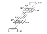
- FIG. 10A is an explanatory diagram of an electric multiplex transmission device showing a configuration of path protection by facing a conventional box type switch (the above-mentioned BOX type electric multiplex transmission device).
- the router 10P in the conventional electric multiplex transmission device, the router 10P, the first transmitter 20P (BOX type electric multiplex transmission device) having the first switch 21P, and the first switch 121P are included.
- the receiver 120P BOX type electric multiplex transmission device of 1 and the router 110P are provided.
- the router 10P is connected to the first transmitter 20P by link aggregation (LAG: Link AGgregation), and the router 110P is connected to the first receiver 120P by link aggregation. Further, the first transmitter 20P and the first receiver 120P are connected by two paths to form path protection.
- LAG Link AGgregation
- the first switch 21P and the first switch 121P are not redundant, for example, the first switch 21P or the first switch 121P When a failure occurs in any of the above, it becomes a single point of failure (SPOF: Single Point Of Failure). In this case, the entire electric multiplex transmission device fails, and the router 10P and the router 110P cannot communicate with each other.
- SPOF Single Point Of Failure
- FIG. 10B is an explanatory diagram of an electric multiplex transmission device to which an MC (Multi-Chassis) -LAG configuration is applied to the configuration shown in FIG. 10A.
- the same components as those in FIG. 10A are designated by the same reference numerals, and the description thereof will be omitted as appropriate.
- the electric multiplex transmission device adopting the MC-LAG configuration includes a router 10P, a first transmitter 20P, a second transmitter 30P having a second switch 31P, and a first transmitter. It is configured to include a receiver 120P, a second receiver 130P having a second switch 131P, and a router 110P.
- the first transmitter 20P and the second transmitter 30P are connected, and are connected to the router 10P by MC-LAG.
- the first receiver 120P and the second receiver 130P are connected, and are connected to the router 110P by MC-LAG.
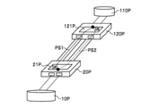
- FIG. 11A is an explanatory diagram of an electric multiplex transmission device to which the current path protection method is applied to the configuration shown in FIG. 10A.
- the first switch 21P and the first switch 121P from the first path PS1 and the second path PS2 constituting one pair of paths, the first path PS1 or the first path PS1 or the first. It is configured to select and switch the path PS2 of 2.
- FIG. 11B is an explanatory diagram of an electric multiplex transmission device to which the MC-LAG configuration is applied to the configuration shown in FIG. 11A.
- the first transmitter 20P and the second transmitter 30P are connected, and the first receiver 120P and the second receiver 130P are connected.
- the current path protection method is applied to the electric multiplex transmission device to which the MC-LAG configuration is applied, two pairs of path protections are provided for each BOX type electric multiplex transmission device facing each other, that is, the first pass PS1 and the first pass. Since the route of the 2nd path PS2 and the route of the 3rd path PS3 and the 4th path PS4 are required, the path resource is doubled as compared with the conventional configuration.
- FIG. 12 is an explanatory diagram showing the problems of the electric multiplex transmission device to which the MC-LAG configuration is applied.
- the electric multiplex transmission apparatus shown in FIG. 11B will be described in detail.
- the same components as those described above are designated by the same reference numerals, and the description thereof will be omitted as appropriate.
- the electric multiplex transmission device 200P shown in FIG. 12 includes a transmission base T and a reception base R.
- the transmission base T and the reception base R are connected by paths 41P and 42P.
- the transmission base T is a facility of a telecommunications carrier in which the transmission side transmission device 40P is installed.
- the transmission base T is provided in the A building.
- the receiving base R is a facility of a telecommunications carrier in which the receiving side transmission device 140P is installed.
- the receiving base R is provided in the B building.
- the transmitting side transmission device 40P includes a first transmitter 20P and a second transmitter 30P.
- the first transmitter 20P is configured to include a first switch 21P.
- the first switch 21P duplicates the signal input from the router 10P at the duplication point C1.
- the first switch 21P replicates (copies) the first main signal at the electrical layer, for example, at the duplication point C1.
- the first switch 21P transmits the signal input from the router 10P to the first receiver 120P via the path 41P, and the duplicated signal at the duplication point C1 is transmitted to the second transmission. Output to the second switch 31P of the machine 30P.
- the second transmitter 30P is configured to include a second switch 31P.
- the second switch 31P duplicates the signal input from the router 10P at the duplication point C2.
- the second switch 31P replicates (copies) the second main signal at the electrical layer, for example, at the duplication point C2.
- the second switch 31P transmits the signal input from the router 10P to the second receiver 130P via the path 42P, and the duplicated signal at the duplication point C2 is transmitted to the first transmission. Output to the first switch 21P of the machine 20P.
- the signal input from the router 10P to the first transmitter 20P is used as the first main signal, and the first main signal is used as the active signal. Further, the signal input from the router 10P to the second transmitter 30P is used as the second main signal, and the second main signal is used as the standby signal. Therefore, in the active state, the second main signal in the standby state is not input to the second transmitter 30P. Further, since the second main signal is a preliminary signal of the first main signal, the first main signal and the second main signal are the same signal.
- the receiving side transmission device 140P includes a first receiver 120P and a second receiver 130P.
- the first receiver 120P is configured to include the first switch 121P.
- the first switch 121P has a first selector 122P.
- the first selector 122P selects and outputs either a signal input from the first transmitter 20P or a signal input from the second receiver 130P. Since the first receiver 120P constitutes the active side, it outputs a signal received from the first transmitter 20P when it is active.
- the second receiver 130P is configured to include a second switch 131P.
- the second switch 131P has a second selector 132P.
- the second selector 132P selects and outputs either the signal input from the second transmitter 30P or the signal input from the first receiver 120P. Since the second receiver 130P constitutes the standby side, it outputs a signal received from the second transmitter 30P during standby.
- each of the path 41P and the path 42P needs to secure the path resource BS1 output from the first transmitter 20P and the path resource BS2 output from the second transmitter 30P.
- the path resource BS2 constituting the standby side is wasted.
- the present invention has been made in view of such a point, and as shown in FIG. 1 described later, the present invention relates to the transmitting side transmission device 40 and the receiving side transmission device 140 between the BOX type electric multiplex transmission devices.
- the transmission side transmission device 40 which is the transmission side SW, is provided with a selector function for selecting a signal
- the reception side transmission device 140 which is the reception side SW, is provided with a copy function for copying the signal.
- the present invention can effectively utilize the path resource of the relay band while ensuring the same redundancy as the conventional one.
- the transmission device 200 including the transmission side transmission device and the reception side transmission device according to the embodiment of the present invention will be described with reference to the drawings.
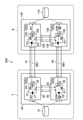
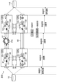
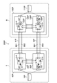
- FIG. 1 is an explanatory diagram showing the configuration of the transmission device 200 according to the present embodiment.
- the same components as those in the comparative example are designated by the same reference numerals, and the description thereof will be omitted as appropriate.
- the transmission device 200 includes a transmission base T and a reception base R.
- the transmission base T and the reception base R are connected by paths 41 and 42.
- the transmission base T is a facility of a telecommunications carrier in which the transmission side transmission device 40 is installed.
- the transmission base T is provided in the A building.
- the receiving base R is a facility of a telecommunications carrier in which the receiving side transmission device 140 is installed.
- the receiving base R is provided in the B building.
- the transmission side transmission device 40 of the transmission base T and the reception side transmission device 140 of the reception base R are box-type switches to which the interface of the switch is fixed.
- the transmission side transmission device 40 and the reception side transmission device 140 configure path protection and secure path resources in the relay band.
- pass protection is configured by the path 41 between the first transmitter 20 and the first receiver 120, and the second transmitter 30 and the second receiver 130. Between, the path 42 constitutes path protection.
- the transmission base T includes a router 10 and a transmission side transmission device 40.
- the router 10 is a device for relaying data exchanges between a plurality of different networks.
- the transmitting side transmission device 40 includes a first transmitter 20 and a second transmitter 30.
- the first transmitter 20 includes a first switch 21 and a CPU (Central Processing Unit) 23.
- the first switch 21 has a first selector 22.
- the first selector 22 selects and outputs either the first main signal input from the router 10 or the duplicate signal of the second main signal input from the second transmitter.
- the first transmitter 20 outputs the signal selected by the first selector 22.
- the signal input from the router 10 to the first transmitter 20 is used as the first main signal.
- the signal input from the router 10 to the second transmitter 30 is used as the second main signal.
- the first main signal is used as an active signal, and the second main signal is used as a standby signal.
- the first switch 21 duplicates the input first main signal at the duplication point C1.
- the first switch 21 replicates (copies) the first main signal at the electrical layer, for example, at the duplication point C1.
- the CPU 23 controls the overall operation of the first transmitter 20, for example, when the first transmitter 20 detects a signal failure, it controls the selection of the signal of the first selector 22.
- the second transmitter 30 includes a second switch 31 and a CPU 33.
- the second switch 31 has a second selector 32.
- the second selector 32 selects and outputs either the input second main signal or the duplicate signal of the first main signal input from the first transmitter.
- the second transmitter 30 outputs the signal selected by the second selector 32.
- the second switch 31 duplicates the input second main signal at the duplication point C2.
- the second switch 31 replicates (copies) the second main signal at the electrical layer, for example, at the duplication point C2.
- the CPU 33 controls the overall operation of the second transmitter 30, for example, when the second transmitter 30 detects a signal failure, it controls the selection of the signal of the second selector 32.
- the second transmitter 30 duplicates the input second main signal and the second main signal is duplicated.
- the duplicate signal of the main signal of 2 is output to the first transmitter 20.
- the first transmitter 20 selects and outputs a duplicate signal of the second main signal input from the second transmitter 30 in the first selector 22.
- the second transmitter 30 When the second transmitter 30 detects a signal failure in the first switch 21, the second transmitter 30 selects and outputs the input second main signal in the second selector 32. do.
- the receiving base R includes a router 110 and a receiving side transmission device 140.
- the router 110 is a device for relaying data exchanges between a plurality of different networks.
- the receiving side transmission device 140 includes a first receiver 120 and a second receiver 130.
- the first receiver 120 includes a first switch 121 and a CPU 123.
- the first switch 121 has a first selector 122.
- the first selector 122 has a first main signal (first received signal) input from the first transmitter 20 and a second main signal (second main signal) input from the second receiver 130. Select and output one of the duplicate signals of the received signal).
- the first receiver 120 outputs the signal selected by the first selector 122.
- the signal received by the first receiver 120 from the first transmitter 20 is used as the first received signal, and the first received signal is used as the active signal.
- the signal received by the second receiver 130 from the second transmitter 30 is used as the second received signal, and the second received signal is used as the standby signal.
- the first switch 121 duplicates the input first received signal at the duplication point C3.
- the first switch 121 duplicates (copies) the first received signal at the electrical layer, for example, at the duplication point C3.
- the CPU 123 controls the overall operation of the first receiver 120. For example, when the first receiver 120 detects a signal failure, it controls the selection of the signal of the first selector 122.
- the second receiver 130 is configured to include a second switch 131 and a CPU 133.
- the second switch 131 has a second selector 132.
- the second selector 132 selects and outputs either the input second received signal or the duplicate signal of the first received signal input from the first receiver 120.
- the second receiver 130 outputs the signal selected by the second selector 132. During standby, the output of the second selector 132 is cut off.
- the second switch 131 duplicates the input second received signal at the duplication point C4.
- the second switch 131 duplicates (copies) the second received signal at the electrical layer, for example, at the duplication point C4.
- the CPU 133 controls the overall operation of the second receiver 130. For example, when the second receiver 130 detects a signal failure, it controls the selection of the signal of the second selector 132.
- the second receiver 130 when the first receiver 120 detects a failure in the first received signal input from the first transmitter 20, the second receiver 130 is from the second transmitter 30.
- the input second received signal is duplicated, and the duplicated signal of the second received signal is output to the first receiver 120.
- the first receiver 120 selects and outputs a duplicate signal of the second received signal input from the second receiver 130 in the first selector 122.
- the second receiver 130 When the second receiver 130 detects a failure in the first switch 121, the second receiver 130 selects and outputs the input second received signal in the second selector 132.
- the first transmitter 20, the second transmitter 30, the first receiver 120, and the second receiver 130 each include the corresponding CPUs 23, 33, 123, 133.
- the present invention is not particularly limited as long as the transmission side transmission device 40 and the reception side transmission device 140 are each provided with a CPU and can detect a signal failure. ..
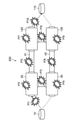
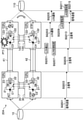
- FIG. 2 is an explanatory diagram showing a failure location in the transmission device 200 according to the present embodiment.
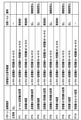
- FIG. 3 is an explanatory diagram showing an example in which the path of the main signal is switched for each failure pattern.
- failure patterns PT1 to PT10 at 10 locations where failures may occur in the route from the router 10 of the transmission device 200 to the router 110 are shown.
- FIG. 3 shows switching of the main signal path for each of the 10 failure patterns PT1 to PT10 corresponding to FIG. 2, and among the 10 failure patterns PT1 to PT10, the failure pattern PT3 is shown. , PT4, PT6, PT8, and PT9 do not need to switch the signal path even if a signal failure occurs.
- the switching sequence occurs because the path through which the main signal passes changes.
- the failure pattern PT1 will be described as Example 1
- the failure pattern PT2 will be described as Example 2
- the failure pattern PT5 will be described as Example 3
- the failure pattern PT7 will be described as Example 4.
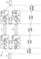
- FIG. 4 is an explanatory diagram showing a state in which the transmission device 200 according to the present embodiment has no faulty part in the signal and is operating normally.
- the transmission device 200 includes a router 10, a first transmitter 20, a second transmitter 30, a path 41, a path 42, a first receiver 120, a second receiver 130, and a router 110. ing.
- the router 10 is connected to the first transmitter 20 and the second transmitter 30 by MC-LAG.
- the first transmitter 20 constitutes the active side
- the second transmitter 30 constitutes the standby side.
- the router 10 transmits the first main signal to the first transmitter 20.
- the second transmitter 30 constitutes the standby side, the input from the router 10 is blocked (SQ501).
- the first switch 21 of the first transmitter 20 inputs the first main signal input from the router 10 to the first selector 22, and at the duplication point C1, duplicates the first main signal.
- the duplicate signal of the first main signal is output to the second selector 32 of the second transmitter 30.
- the first selector 22 of the first transmitter 20 selects the first main signal and outputs it to the first receiver 120.
- the second selector 32 of the second transmitter 30 selects a duplicate signal of the first main signal input from the first switch 21 of the first transmitter 20 to select a second receiver. Output to 130 (SQ503).
- the first main signal output from the first selector 22 is input to the first receiver 120 via the path 41. Further, the duplicate signal of the first main signal output from the second selector 32 is input to the second receiver 130 via the path 42 (SQ505).
- the first switch 121 of the first receiver 120 inputs the first received signal (first main signal) input from the first transmitter 20 to the first selector 122, and the duplication point C3. In, the duplicated signal of the first received signal is duplicated, and the duplicated signal of the first received signal is output to the second receiver 130.
- the second switch 131 of the second receiver 130 inputs the second received signal (duplicate signal of the first main signal) input from the second transmitter 30 to the second selector 132, and also inputs it to the second selector 132.
- the second received signal is duplicated, and the duplicated signal of the second received signal is output to the first receiver 120.
- the first selector 122 of the first receiver 120 selects and outputs the first received signal when it is active. On the other hand, even if the second selector 132 of the second receiver 130 selects the duplicate signal of the first received signal, the output is cut off because it is on the standby side (SQ507).
- the first received signal output from the first receiver 120 is transmitted to the router 110 (SQ509).
- the first main signal transmitted from the router 10 is output from the first selector 122 of the first receiver 120 and transmitted to the router 110.
- Example 1 the failure pattern PT1 shown in FIGS. 2 and 3 will be described.
- the second transmitter 30 duplicates the input second main signal. Then, the duplicated signal of the second main signal is output to the first transmitter 20.
- the first transmitter 20 selects and outputs a duplicate signal of the second main signal input from the second transmitter 30 in the first selector 22.
- FIG. 5 shows that in the transmission device 201 according to the present embodiment, when a failure occurs between the router 10 and the first transmitter 20, the first transmitter 20 and the second transmitter 30 execute. It is a sequence diagram which shows the flow of a route switching process (path protection). The same processing as in FIG. 4 will be omitted as appropriate.
- the first selector 22 and the second selector 22 of the first transmitter 20 are triggered by the failure detection (that is, the failure detection).
- the second selector 32 of the transmitter 30 of the above is switched.
- the failure between the router 10 and the first transmitter 20 is determined by the failure of the signal received by the first transmitter 20. In this case, by detecting the failure of the signal, the failure between the router 10 and the first transmitter 20 can be detected.
- the CPU 23 of the first transmitter 20 detects LOS (Loss of Signal) (SQ001). ..
- the CPU 23 of the first transmitter 20 detects the LOS of the first main signal, it notifies the router 10 that there is a failure by the LOS notification (SQ003), and at the same time, the first transmitter 20 to the second transmitter 20 Notify the transmitter 30 of the failure (SQ005).
- the router 10 When the router 10 receives the LOS notification, it waits for switching the signal transmitted by the router 10 from the first main signal to the second main signal (SQ007). Similarly, the first transmitter 20 and the second transmitter 30 also perform standby for switching the signal transmitted by the router 10 from the first main signal to the second main signal (SQ009).
- the CPU 23 of the first transmitter 20 executes, in the first selector 22, a switching process of switching from the first main signal at the active time to the duplicate signal of the second main signal at the standby time, and at the same time, the second The CPU 33 of the transmitter 30 executes a switching process of switching from the first main signal during active to the second main signal during standby in the second selector 32 (SQ011).
- the CPU 23 of the first transmitter 20 and the CPU 33 of the second transmitter 30 give a switching completion notification (SQ013, SQ015), and the router 10 and the second.
- the transmitter 20 and the second transmitter 30 of 1 execute a switching process of switching from the first main signal at the time of active to the second main signal at the time of standby (SQ017, SQ019).
- the router 10 transmits the second main signal to the second transmitter 30 (SQ021).
- the CPU 33 of the second transmitter 30 When the CPU 33 of the second transmitter 30 receives the second main signal, it duplicates it and outputs the duplicate signal of the second main signal to the first transmitter 20 (SQ023).
- the first selector 22 of the first transmitter 20 outputs a duplicate signal of the second main signal input from the second transmitter 30 to the first receiver 120 via the path 41 (SQ025). ).
- the first receiver 120 inputs the input first received signal (duplicate signal of the second main signal) to the first switch 121, and the first selector 122 of the first receiver 120 sets the first selector 122.
- the first received signal is selected and output (SQ027).
- the first receiver 120 receives the input first received signal, duplicates the input first received signal at the duplication point C3, and duplicates the first received signal into the second. To the receiver 130 of.
- the first receiver 120 transmits the first received signal to the router 110 (SQ029), and ends the route switching process of the failure pattern PT1.
- Example 2 the failure pattern PT2 shown in FIGS. 2 and 3 will be described.
- the second transmitter 30 uses the input second main signal as the second main signal. Select and output in the selector 32 of 2.
- FIG. 6 shows the flow of the route switching process executed by the first transmitter 20 and the second transmitter 30 when a failure occurs in the first transmitter 20 in the transmission device 202 according to the present embodiment. It is a sequence diagram which shows. The same processing as in FIGS. 4 and 5 will be omitted as appropriate.
- the path control is executed by using the failure detection in the own device (transmitting side transmission device 40) as a trigger.
- the CPU 33 of the second transmitter 30 detects the LOS (SQ101).
- the CPU 33 of the second transmitter 30 detects the LOS, it notifies the router 10 that the first transmitter 20 has failed by the LOS notification (SQ103, SQ105), and at the same time, informs the first receiver 120. LOS notification is performed (SQ107).
- the router 10 When the router 10 receives the LOS notification, it waits for switching the signal transmitted by the router 10 from the first main signal to the second main signal (SQ109).
- the CPU 123 of the first receiver 120 When the CPU 123 of the first receiver 120 receives the LOS notification from the second transmitter 30, the CPU 123 switches the selection from the first received signal to the duplicate signal of the second received signal in the first selector 122. (SQ111).
- the CPU 33 of the second transmitter 30 executes a switching process of switching from the first main signal during active to the second main signal during standby in the second selector 32 (SQ113).
- the CPU 33 of the second transmitter 30 notifies the router 10 of the completion of switching (SQ115, SQ117), and the router 10 and the second transmitter 30 are the first main when active.
- the switching process for switching from the signal to the second main signal during standby is executed (SQ119, SQ121).
- the second transmitter 30 When the switching process for switching to the second main signal during standby is completed, the second transmitter 30 notifies that the switching process is completed (SQ123). Note that the notification that this switching process is completed is a process that can be arbitrarily provided depending on the difference in standards and specifications.
- the router 10 When the router 10 receives the notification from the second transmitter 30 that the switching process is completed, the router 10 transmits the second main signal to the second transmitter 30 (SQ125).
- the CPU 33 of the second transmitter 30 selects and outputs the second main signal transmitted from the router 10 in the second selector 32 (SQ127).
- the second transmitter 30 transmits the second main signal to the second receiver 130 via the path 42 (SQ129).
- the second receiver 130 receives the input second received signal (second main signal), duplicates the second received signal at the duplication point C4, and duplicates the second received signal. Output to the first receiver 120.
- the first receiver 120 outputs a duplicate signal of the second received signal input from the second receiver 130 in the first selector 122 (SQ131).
- the first receiver 120 transmits the duplicate signal of the second received signal to the router 110 (SQ133), and ends the route switching process of the failure pattern PT2.
- Example 3 the failure pattern PT5 shown in FIGS. 2 and 3 will be described.
- the second receiver 130 duplicates the input second received signal. Then, the duplicated signal of the second received signal is output to the first receiver 120. The first receiver 120 selects and outputs a duplicate signal of the second received signal input from the second receiver 130 in the first selector 122.
- FIG. 7 shows the first receiver 120 and the second receiver when a failure occurs in the section between the first transmitter 20 and the first receiver 120 in the transmission device 203 according to the present embodiment. It is a sequence diagram which shows the flow of the route switching process executed by 130. The same processing as in FIGS. 4, 5 and 6 will be omitted as appropriate.
- the first receiver 120 when a failure occurs in the section between the first transmitter 20 and the first receiver 120, the first receiver 120 is triggered by the failure detection (fault detection) of the first receiver 120. Switching is executed in the first selector 122 included in the first switch 121 of the receiver 120.
- the first transmitter 20 outputs the first main signal to the first receiver 120
- the second receiver 130 is a duplicate signal of the first main signal. Is output to the second receiver 130 (see SQ503 in FIG. 4).
- the first receiver 120 When a failure occurs in the section between the first transmitter 20 and the first receiver 120, the first receiver 120 cannot receive the first main signal, and the failure detection (failure). Detect).
- the second receiver 130 receives the duplicate signal (second received signal) of the first main signal output from the second transmitter 30 via the path 42 (SQ505). ). Further, the second switch 131 of the second receiver 130 further duplicates the duplicated signal of the first main signal at the duplication point C4, and the duplicated signal of the first main signal is further duplicated. That is, the duplicate signal of the second received signal is output to the first receiver 120.
- the CPU 123 of the first receiver 120 switches the output signal of the first selector 122 from the first received signal (first main signal) to the duplicate signal of the second received signal (SQ203).
- the first switch 121 of the first receiver 120 outputs a duplicate signal of the second received signal input from the second receiver 130 (SQ205).
- the first receiver 120 transmits a duplicate signal of the second received signal output from the first switch 121 to the router 110 (SQ207).
- the first receiver 120 transmits the duplicate signal of the second received signal to the router 110, and ends the route switching process of the failure pattern PT5.
- Example 4 the failure pattern PT7 shown in FIGS. 2 and 3 will be described.
- the second receiver 130 detects a signal failure in the first switch 121 of the first receiver 120
- the second receiver 130 is the second selector.
- the input second received signal is selected and output.
- FIG. 8 is a sequence diagram showing a flow of route switching processing executed by the second receiver 130 when a failure occurs in the first receiver 120 in the transmission device 204 according to the present embodiment. The same processing as in FIGS. 4, 5, 6 and 7 will be omitted as appropriate.
- the second receiver 130 when a failure occurs in the first receiver 120, the second receiver 130 triggers the failure detection of the first receiver 120 to trigger the second selector 132 in the second receiver 130. Perform a switch.
- the first receiver 120 receives the first received signal (first main signal) input from the first transmitter 20 (see SQ505 in FIG. 4).
- the duplicate signal of the first received signal is output to the second receiver 130 (see SQ507 in FIG. 4).
- the second receiver 130 receives the second received signal (duplicate signal of the first main signal) input from the second transmitter 30 (see SQ505 in FIG. 4), and the second received signal. Is output to the first receiver 120 (see SQ507 in FIG. 4).
- the second receiver 130 detects the failure from the duplicate signal of the first received signal input from the first receiver 120.
- the CPU 133 of the second receiver 130 detects LOS from the duplicate signal of the first received signal (SQ301).
- the CPU 133 detects the LOS, the CPU 133 notifies the router 110 of the LOS (SQ303, SQ305).
- the CPU 133 of the second receiver 130 detects the LOS, it performs a switching process of switching the selection from the duplicate signal of the first received signal to the second received signal in the second selector 132 (SQ307).
- the CPU 133 of the second receiver 130 executes a switching process of switching the output signal transmitted to the router 110 from the first receiver 120 to the second receiver 130 (SQ309), and the router 110 sets the router 110.
- a process of switching the signal received from the receiving side transmission device 140 from the first receiver 120 to the second receiver 130 is executed (SQ311).
- the second selector 132 of the second receiver 130 selects and outputs the second received signal (SQ313). Then, the second receiver 130 transmits the second received signal from the second selector 132 to the router 110 (SQ315).
- the control of the transmission side transmission device 40 and the reception side transmission device 140 according to the present embodiment is realized by, for example, a computer 900 as shown in FIG.
- the computer 900 includes a first transmitter 20 having a first switch 21 and a second transmitter 30 having a second switch 31 (see FIG. 1), thereby providing a transmitting side transmission device. 40 is configured. Further, the computer 900 includes a first receiver 120 having a first switch 121 and a second receiver 130 having a second switch 131 (see FIG. 1), whereby the receiving side transmission device 140 Is configured.
- FIG. 9 is a hardware configuration diagram showing an example of a computer 900 that realizes control of the transmission side transmission device 40 and the reception side transmission device 140 according to the present embodiment.
- the computer 900 includes a CPU (Central Processing Unit) 901, a ROM (Read Only Memory) 902, a RAM 903, an HDD (Hard Disk Drive) 904, an input / output I / F (Interface) 905, a communication I / F906, and a media I / F907. Have.
- CPU Central Processing Unit
- ROM Read Only Memory
- HDD Hard Disk Drive
- I / F Interface
- the CPU 901 operates based on the program stored in the ROM 902 or the HDD 904, and realizes the control of the transmission side transmission device 40 and the reception side transmission device 140 shown in FIG.
- the ROM 902 stores a boot program executed by the CPU 901 when the computer 900 is started, a program related to the hardware of the computer 900, and the like.
- the CPU 901 controls an input device 910 such as a mouse and a keyboard and an output device 911 such as a display via the input / output I / F 905.
- the CPU 901 acquires data from the input device 910 and outputs the generated data to the output device 911 via the input / output I / F 905.
- a GPU or the like may be used together with the CPU 901 as the processor.
- the HDD 904 stores a program executed by the CPU 901, data used by the program, and the like.
- the communication I / F906 receives data from another device via a communication network (for example, NW (Network) 920) and outputs the data to the CPU 901, and the communication I / F 906 transfers the data generated by the CPU 901 to another device via the communication network. Send to the device.
- NW Network
- the media I / F907 reads the program or data stored in the recording medium 912 and outputs the program or data to the CPU 901 via the RAM 903.
- the CPU 901 loads the program related to the target processing from the recording medium 912 onto the RAM 903 via the media I / F 907, and executes the loaded program.
- the recording medium 912 is an optical recording medium such as a DVD (Digital Versatile Disc) or PD (Phase change rewritable Disk), a magneto-optical recording medium such as an MO (Magneto Optical disk), a magnetic recording medium, a conductor memory tape medium, a semiconductor memory, or the like. Is.
- the CPU 901 of the computer 900 realizes control of the transmission side transmission device 40 by executing a program loaded on the RAM 903. do.
- the CPU 901 controls the entire transmission side transmission device 40 by one CPU, but like the CPU 23 and the CPU 33 (see FIG. 1), the first transmitter 20 and the second transmitter 20 It may be provided in each of the transmitters 30.
- the CPU 901 of the computer 900 realizes the control of the receiving side transmission device 140 by executing the program loaded on the RAM 903. do.
- the CPU 901 controls the entire receiving side transmission device 140 by one CPU, but like the CPU 123 and the CPU 133 (see FIG. 1), the first receiver 120 and the second receiver 120 and the second. It may be provided in each of the receivers 130 of the above.
- the data in the RAM 903 is stored in the HDD 904.
- the CPU 901 reads the program related to the target processing from the recording medium 912 and executes it.
- the CPU 901 may read a program related to the target processing from another device via the communication network (NW920).
- the transmitting side transmitting device 40 is a transmitting side transmitting device including a first transmitter 20 having a first switch 21 and a second transmitter 30 having a second switch 31.
- the first switch 21 of the first transmitter 20 selects either the input first main signal or the duplicate signal of the second main signal input from the second transmitter 30.
- the second switch 31 of the second transmitter 30 having the first selector 22 to output has the input second main signal and the first main signal input from the first transmitter 20.
- the second transmitter has a second selector 32 that selects and outputs one of the duplicated signals of the above, and when the first transmitter 20 detects a failure in the input first main signal, the second transmitter 30 duplicates the input second main signal, outputs the duplicate signal of the second main signal to the first transmitter 20, and the first transmitter 20 is from the second transmitter 30.
- the second transmitter is used. 30 is characterized in that the input second main signal is selected and output by the second selector 32.
- the second transmitter 30 duplicates the input second main signal and the second main signal is duplicated.
- the duplicate signal of the main signal is output to the first transmitter 20.
- the first transmitter 20 selects and outputs a duplicate signal of the second main signal input from the second transmitter 30 in the first selector 22.
- the second transmitter 30 When the second transmitter 30 detects a signal failure in the first switch 21, the second transmitter 30 selects and outputs the input second main signal in the second selector 32. do.
- the transmission side transmission device 40 can effectively utilize the path resource of the relay band while ensuring the same redundancy as the conventional one.
- the receiving side transmission device 140 is a receiving side transmission device including a first receiver 120 having a first switch 121 and a second receiver 130 having a second switch 131.
- the first switch 121 of the first receiver 120 selects either the input first received signal or the duplicate signal of the second received signal input from the second receiver 130.
- the second switch 131 of the second receiver 130 having the first selector 122 to output has the input second receive signal and the first receive signal input from the first receiver 120.
- the second selector 132 that selects and outputs one of the duplicated signals of the above, and when the first receiver 120 detects a failure in the input first received signal, the second receiver The 130 duplicates the input second received signal, outputs the duplicate signal of the second received signal to the first receiver 120, and the first receiver 120 is from the second receiver 130.
- the second is The receiver 130 is characterized in that the input second received signal is selected and output by the second selector 132.
- the first receiver 120 detects a failure in the first received signal input from the first transmitter 20, the second receiver 130 is input from the second transmitter 30.
- the second received signal is duplicated, and the duplicated signal of the second received signal is output to the first receiver 120.
- the first receiver 120 selects and outputs a duplicate signal of the second received signal input from the second receiver 130 in the first selector 122.
- the second receiver 130 When the second receiver 130 detects a failure in the first switch 121, the second receiver 130 selects and outputs the input second received signal in the second selector 132.
- the receiving side transmission device 140 can effectively utilize the path resource of the relay band while ensuring the same redundancy as the conventional one.
Landscapes
- Engineering & Computer Science (AREA)
- Theoretical Computer Science (AREA)
- Quality & Reliability (AREA)
- Physics & Mathematics (AREA)
- General Engineering & Computer Science (AREA)
- General Physics & Mathematics (AREA)
- Computer Networks & Wireless Communication (AREA)
- Signal Processing (AREA)
- Data Exchanges In Wide-Area Networks (AREA)
Abstract
送信側伝送装置(40)は、第1のスイッチ(21)を有する第1の送信機(20)と、第2のスイッチ(31)を有する第2の送信機(30)とを備える。第1の送信機(20)が、第1の主信号において故障を検出した場合、第2の送信機(30)は、第2の主信号の複製信号を第1の送信機(20)に出力する。第1の送信機(20)は、入力された第2の主信号の複製信号を、第1のセレクタ(22)において選択して出力する。第2の送信機(30)が、第1のスイッチ(21)において故障を検出した場合、第2の送信機(30)は、第2の主信号を選択して出力する。
Description
本発明は、送信側伝送装置、受信側伝送装置、送信側伝送装置の冗長化方法、受信側伝送装置の冗長化方法、プログラム、及び伝送装置に関する。
従来、通信事業者における電気多重伝送装置のシステム構成方法として、監視制御部やスイッチ(SW:Switch)部が冗長化されたシャーシ型構成が一般的であったが、近年データセンタトラヒックの急激な増加に対し、データセンタ事業者への要望に応じるべく、省スペースかつ低コストなボックス型構成の電気多重伝送装置が広く普及している。このボックス型構成の電気多重装置伝送装置(以下、これをBOX型電気多重伝送装置という)は、省スペースかつコスト低減を図るため監視制御部やSW部が冗長化されておらず、シャーシ型構成に対して故障時や障害時において信頼性が劣る。このため、BOX型電気多重伝送装置の信頼性向上を図るためにMC-LAG(Multi-Chassis Link-AGgregation)構成が適用される。
また、従来の電気多重伝送装置においては、ルータ、レイヤ2スイッチ等のクライアント装置からの信号をレイヤ1及びレイヤ2の論理パス(例えば、OTN(Optical Transport Network)、VLAN(Virtual Local Area Network)、MPLS(Multi-Protocol Label Switching)等)にマッピングすることで、論理パス単位での冗長構成(パスプロテクション)を実現し、電気多重伝送装置区間における障害に対し、信頼性の向上を図っている(例えば、非特許文献1参照)。
TTC標準 JT-G8031,"イーサネットリニアプロテクション切替",[online],2011年5月31日制定,一般社団法人 情報通信技術委員会,[令和2年7月1日検索],インターネット<URL:https://www.ttc.or.jp/application/files/9015/5425/7356/JT-G8031v1.pdf>,p.15-21
MC-LAG構成において、従来の電気多重伝送装置で提供されてきたパスプロテクション(path protection)の実現について検討する。例えば、MC-LAG構成において現行のパスプロテクション方式を適用すると、対向するBOX型電気多重伝送装置毎にパスプロテクションが必要となるため(2ペア)、中継帯域のパスリソース(アクティブ及びスタンバイ)が、従来のシャーシ型電気多重伝送装置構成に対して2倍確保する必要がある。
すなわち、対向するBOX型電気多重伝送装置間においてパスプロテクションを構成するため、中継帯域のパスリソースをアクティブとスタンバイのそれぞれについて確保する必要がある。ここで、MC-LAGのトラヒックの振分方式をアクト―スタンバイとすると、この場合、トラフィックは、BOX型電気多重伝送装置間のアクティブ(ACT)側しか信号が流れないため、スタンバイ(STBY)側で確保するパスリソースが無駄になる、という課題がある。
このような点に鑑みて本発明がなされたのであり、本発明は、従来と同様な冗長性を確保しつつ、中継帯域のパスリソースの有効活用を図ることを課題とする。
本発明に係る送信側伝送装置は、
第1のスイッチを有する第1の送信機と、第2のスイッチを有する第2の送信機とを備える送信側伝送装置であって、
前記第1の送信機の前記第1のスイッチは、
入力された第1の主信号と、前記第2の送信機から入力された第2の主信号の複製信号のいずれか一方を選択して出力する第1のセレクタを有し、
前記第2の送信機の前記第2のスイッチは、
入力された第2の主信号と、前記第1の送信機から入力された第1の主信号の複製信号のいずれか一方を選択して出力する第2のセレクタを有し、
前記第1の送信機が、入力された前記第1の主信号において故障を検出した場合、
第1のスイッチを有する第1の送信機と、第2のスイッチを有する第2の送信機とを備える送信側伝送装置であって、
前記第1の送信機の前記第1のスイッチは、
入力された第1の主信号と、前記第2の送信機から入力された第2の主信号の複製信号のいずれか一方を選択して出力する第1のセレクタを有し、
前記第2の送信機の前記第2のスイッチは、
入力された第2の主信号と、前記第1の送信機から入力された第1の主信号の複製信号のいずれか一方を選択して出力する第2のセレクタを有し、
前記第1の送信機が、入力された前記第1の主信号において故障を検出した場合、
前記第2の送信機は、
入力された前記第2の主信号を複製し、当該第2の主信号の複製信号を前記第1の送信機に出力し、
前記第1の送信機は、
前記第2の送信機から入力された前記第2の主信号の複製信号を、前記第1のセレクタにおいて選択して出力し、
前記第2の送信機が、前記第1のスイッチにおいて故障を検出した場合、
前記第2の送信機は、
入力された前記第2の主信号を、前記第2のセレクタにおいて選択して出力する、ことを特徴とする。
入力された前記第2の主信号を複製し、当該第2の主信号の複製信号を前記第1の送信機に出力し、
前記第1の送信機は、
前記第2の送信機から入力された前記第2の主信号の複製信号を、前記第1のセレクタにおいて選択して出力し、
前記第2の送信機が、前記第1のスイッチにおいて故障を検出した場合、
前記第2の送信機は、
入力された前記第2の主信号を、前記第2のセレクタにおいて選択して出力する、ことを特徴とする。
本発明によれば、従来と同様な冗長性を確保しつつ、中継帯域のパスリソースの有効活用を図ることができる。
次に、本発明を実施するための形態について説明する。まず、比較例として、従来技術について説明する。
<比較例>
図10Aは、従来のボックス型スイッチ(上述したBOX型電気多重伝送装置である。)を対向させ、パスプロテクションの構成を示した電気多重伝送装置の説明図である。
図10Aは、従来のボックス型スイッチ(上述したBOX型電気多重伝送装置である。)を対向させ、パスプロテクションの構成を示した電気多重伝送装置の説明図である。
図10Aに示すように、従来の電気多重伝送装置では、ルータ10Pと、第1のスイッチ21Pを有する第1の送信機20P(BOX型電気多重伝送装置)と、第1のスイッチ121Pを有する第1の受信機120P(BOX型電気多重伝送装置)と、ルータ110Pとを備えて構成されている。
従来の電気多重伝送装置は、第1の送信機20Pにルータ10Pがリンクアグリゲーション(LAG:Link AGgregation)により接続されており、第1の受信機120Pにルータ110Pがリンクアグリゲーションにより接続されている。また、第1の送信機20Pと第1の受信機120Pは、2本のパスで接続されており、パスプロテクションを構成している。
ここで、第1の送信機20P及び第1の受信機120Pは、第1のスイッチ21P及び第1のスイッチ121Pが冗長化されていないため、例えば、第1のスイッチ21P又は第1のスイッチ121Pのいずれかに障害が発生すると、単一障害点(SPOF:Single Point Of Failure)になる。この場合、電気多重伝送装置全体が故障となり、ルータ10P及びルータ110Pは、通信をすることができなくなる。
図10Bは、図10Aに示した構成に、MC(Multi-Chassis)-LAG構成を適用した電気多重伝送装置の説明図である。図10Aと同一の構成には、同一の符号を付し、説明を適宜省略する。
図10Bに示すように、MC-LAG構成を採用した電気多重伝送装置は、ルータ10Pと、第1の送信機20Pと、第2のスイッチ31Pを有する第2の送信機30Pと、第1の受信機120Pと、第2のスイッチ131Pを有する第2の受信機130Pと、ルータ110Pとを備えて構成されている。
第1の送信機20Pと第2の送信機30Pは、接続されており、ルータ10PにMC-LAGにより接続されている。同様に、第1の受信機120Pと第2の受信機130Pは、接続されており、ルータ110PにMC-LAGにより接続されている。
図11Aは、図10Aに示した構成に、現行のパスプロテクション方式を適用した電気多重伝送装置の説明図である。
図11Aに示す電気多重伝送装置では、第1のスイッチ21P及び第1のスイッチ121Pにおいて、1ペアの経路を構成する第1のパスPS1と第2のパスPS2から、第1のパスPS1又は第2のパスPS2を選択して切り替える構成になっている。
図11Bは、図11Aに示した構成に、MC-LAG構成を適用した電気多重伝送装置の説明図である。
図11Bに示すように、第1の送信機20Pと第2の送信機30Pは、接続されており、第1の受信機120Pと第2の受信機130Pは、接続されている。この場合、MC-LAG構成を適用した電気多重伝送装置に、現行のパスプロテクション方式を適用すると、対向するBOX型電気多重伝送装置毎にパスプロテクションが2ペア、すなわち、第1のパスPS1及び第2のパスPS2の経路と、第3のパスPS3及び第4のパスPS4の経路とが必要となるため、パスリソースが従来の構成に対して、2倍必要になる。
図12は、MC-LAG構成を適用した電気多重伝送装置の問題点を示した説明図である。図12では、図11Bで示した電気多重伝送装置について、詳述する。なお、上述した構成と同一の構成については同一の符号を付し、説明を適宜、省略する。
図12に示す電気多重伝送装置200Pは、送信拠点Tと、受信拠点Rとを含んで構成されている。送信拠点Tと受信拠点Rは、パス41P,42Pで接続されている。送信拠点Tは、送信側伝送装置40Pが設置された通信事業者の施設である。送信拠点Tは、Aビルに設けられている。一方、受信拠点Rは、受信側伝送装置140Pが設置された通信事業者の施設である。受信拠点Rは、Bビルに設けられている。
送信側伝送装置40Pは、第1の送信機20Pと第2の送信機30Pとを備えて構成されている。第1の送信機20Pは、第1のスイッチ21Pを備えて構成されている。第1のスイッチ21Pは、複製点C1において、ルータ10Pから入力された信号を複製する。第1のスイッチ21Pは、例えば、複製点C1において電気レイヤで第1の主信号を複製(コピー)する。この場合、第1のスイッチ21Pは、ルータ10Pから入力された信号を、パス41Pを介して、第1の受信機120Pに送信するとともに、複製点C1において複製した複製信号を、第2の送信機30Pの第2のスイッチ31Pに出力する。
第2の送信機30Pは、第2のスイッチ31Pを備えて構成されている。第2のスイッチ31Pは、複製点C2において、ルータ10Pから入力された信号を複製する。第2のスイッチ31Pは、例えば、複製点C2において電気レイヤで第2の主信号を複製(コピー)する。この場合、第2のスイッチ31Pは、ルータ10Pから入力された信号を、パス42Pを介して、第2の受信機130Pに送信するとともに、複製点C2において複製した複製信号を、第1の送信機20Pの第1のスイッチ21Pに出力する。
ここでは、第1の送信機20Pにルータ10Pから入力される信号を、第1の主信号とし、第1の主信号をアクティブ時の信号とする。また、第2の送信機30Pにルータ10Pから入力される信号を、第2の主信号とし、第2の主信号をスタンバイ時の信号とする。そのため、アクティブ時において、スタンバイ時の第2の主信号は、第2の送信機30Pに入力されない。また、第2の主信号は、第1の主信号の予備信号であるため、第1の主信号と第2の主信号は、同一の信号である。
一方、受信側伝送装置140Pは、第1の受信機120Pと第2の受信機130Pとを備えて構成されている。
第1の受信機120Pは、第1のスイッチ121Pを備えて構成されている。第1のスイッチ121Pは、第1のセレクタ122Pを有している。
第1のセレクタ122Pは、第1の送信機20Pから入力された信号と、第2の受信機130Pから入力された信号のいずれか一方を選択して出力する。第1の受信機120Pは、アクティブ側を構成するため、アクティブ時に第1の送信機20Pから受信する信号を出力する。
第2の受信機130Pは、第2のスイッチ131Pを備えて構成されている。第2のスイッチ131Pは、第2のセレクタ132Pを有している。
第2のセレクタ132Pは、第2の送信機30Pから入力された信号と、第1の受信機120Pから入力された信号のいずれか一方を選択して出力する。第2の受信機130Pは、スタンバイ側を構成するため、スタンバイ時に第2の送信機30Pから受信する信号を出力する。
この場合、パス41Pとパス42Pのそれぞれは、第1の送信機20Pから出力されるパスリソースBS1と、第2の送信機30Pから出力されるパスリソースBS2とを確保する必要がある。しかしながら、パス41P及びパス42Pのトラヒックは、アクティブ時はパスリソースBS1しか信号が流れないため、スタンバイ側を構成するパスリソースBS2が、無駄になる。
このような点に鑑みて本発明がなされたのであり、本発明は、後記する図1で示すように、BOX型電気多重伝送装置間である送信側伝送装置40と受信側伝送装置140とにおいて、送信側SWである送信側伝送装置40に信号を選択するセレクタ機能を設けるとともに、受信側SWである受信側伝送装置140に信号をコピーするコピー機能とを設ける。
これにより、本発明は、従来と同様な冗長性を確保しつつ、中継帯域のパスリソースの有効活用を図ることができる。
<本実施形態>
以下、本発明の実施形態に係る、送信側伝送装置、及び受信側伝送装置を備える伝送装置200について、図面を参照しながら説明する。
以下、本発明の実施形態に係る、送信側伝送装置、及び受信側伝送装置を備える伝送装置200について、図面を参照しながら説明する。
図1は、本実施形態に係る伝送装置200の構成を示した説明図である。なお、比較例と同一の構成については同一の符号を付し、説明を適宜、省略する。
図1に示すように、伝送装置200は、送信拠点Tと、受信拠点Rとを含んで構成されている。送信拠点Tと受信拠点Rは、パス41,42で接続されている。送信拠点Tは、送信側伝送装置40が設置された通信事業者の施設である。送信拠点Tは、Aビルに設けられている。一方、受信拠点Rは、受信側伝送装置140が設置された通信事業者の施設である。受信拠点Rは、Bビルに設けられている。
送信拠点Tの送信側伝送装置40と、受信拠点Rの受信側伝送装置140は、スイッチのインターフェースが固定されているボックス型スイッチである。伝送装置200において、送信側伝送装置40と受信側伝送装置140は、パスプロテクションを構成し、中継帯域のパスリソースを確保する。具体的には、第1の送信機20と、第1の受信機120との間で、パス41によりパスプロテクションが構成され、また、第2の送信機30と、第2の受信機130との間で、パス42によりパスプロテクションが構成される。
まず、送信拠点Tについて説明する。送信拠点Tは、ルータ10と、送信側伝送装置40とを含んで構成されている。ルータ10は、複数の異なるネットワーク間でデータのやりとりを中継するための装置である。
送信側伝送装置40は、第1の送信機20と、第2の送信機30とを備えて構成されている。第1の送信機20は、第1のスイッチ21、及びCPU(Central Processing Unit)23を備えて構成されている。第1のスイッチ21は、第1のセレクタ22を有している。
第1のセレクタ22は、ルータ10から入力された第1の主信号と、第2の送信機から入力された第2の主信号の複製信号のいずれか一方を選択して出力する。第1の送信機20は、第1のセレクタ22において選択された信号を出力する。ここでは、第1の送信機20にルータ10から入力される信号を、第1の主信号とする。また、第2の送信機30にルータ10から入力される信号を、第2の主信号とする。また、第1の主信号をアクティブ時の信号とし、第2の主信号をスタンバイ時の信号とする。
第1のスイッチ21は、複製点C1において、入力された第1の主信号を複製する。第1のスイッチ21は、例えば、複製点C1において電気レイヤで第1の主信号を複製(コピー)する。
CPU23は、第1の送信機20の全体の動作を制御しており、例えば、第1の送信機20において信号の故障を検出すると、第1のセレクタ22の信号の選択を制御する。
第2の送信機30は、第2のスイッチ31、及びCPU33を備えて構成されている。第2のスイッチ31は、第2のセレクタ32を有している。
第2のセレクタ32は、入力された第2の主信号と、第1の送信機から入力された第1の主信号の複製信号のいずれか一方を選択して出力する。第2の送信機30は、第2のセレクタ32において選択された信号を出力する。
第2のスイッチ31は、複製点C2において、入力された第2の主信号を複製する。第2のスイッチ31は、例えば、複製点C2において電気レイヤで第2の主信号を複製(コピー)する。
CPU33は、第2の送信機30の全体の動作を制御しており、例えば、第2の送信機30において信号の故障を検出すると、第2のセレクタ32の信号の選択を制御する。
本実施形態では、第1の送信機20が、入力された第1の主信号において故障を検出した場合、第2の送信機30は、入力された第2の主信号を複製し、当該第2の主信号の複製信号を第1の送信機20に出力する。第1の送信機20は、第2の送信機30から入力された第2の主信号の複製信号を、第1のセレクタ22において選択して出力する。
第2の送信機30が、第1のスイッチ21において信号の故障を検出した場合、第2の送信機30は、入力された第2の主信号を、第2のセレクタ32において選択して出力する。
次に、受信拠点Rについて説明する。受信拠点Rは、ルータ110と、受信側伝送装置140とを含んで構成されている。ルータ110は、複数の異なるネットワーク間でデータのやりとりを中継するための装置である。
受信側伝送装置140は、第1の受信機120と、第2の受信機130とを備えて構成されている。第1の受信機120は、第1のスイッチ121、及びCPU123を備えて構成されている。第1のスイッチ121は、第1のセレクタ122を有している。
第1のセレクタ122は、第1の送信機20から入力された第1の主信号(第1の受信信号)と、第2の受信機130から入力された第2の主信号(第2の受信信号)の複製信号のいずれか一方を選択して出力する。第1の受信機120は、第1のセレクタ122において選択された信号を出力する。ここでは、第1の受信機120が第1の送信機20から受信する信号を、第1の受信信号とし、第1の受信信号をアクティブ時の信号とする。また、第2の受信機130が第2の送信機30から受信する信号を、第2の受信信号とし、第2の受信信号をスタンバイ時の信号とする。
第1のスイッチ121は、複製点C3において、入力された第1の受信信号を複製する。第1のスイッチ121は、例えば、複製点C3において電気レイヤで第1の受信信号を複製(コピー)する。
CPU123は、第1の受信機120の全体の動作を制御しており、例えば、第1の受信機120において信号の故障を検出すると、第1のセレクタ122の信号の選択を制御する。
第2の受信機130は、第2のスイッチ131、及びCPU133を備えて構成されている。第2のスイッチ131は、第2のセレクタ132を有している。
第2のセレクタ132は、入力された第2の受信信号と、第1の受信機120から入力された第1の受信信号の複製信号のいずれか一方を選択して出力する。第2の受信機130は、第2のセレクタ132において選択された信号を出力する。なお、スタンバイ時は、第2のセレクタ132の出力が遮断される。
第2のスイッチ131は、複製点C4において、入力された第2の受信信号を複製する。第2のスイッチ131は、例えば、複製点C4において電気レイヤで第2の受信信号を複製(コピー)する。
CPU133は、第2の受信機130の全体の動作を制御しており、例えば、第2の受信機130において信号の故障を検出すると、第2のセレクタ132の信号の選択を制御する。
本実施形態では、第1の受信機120が、第1の送信機20から入力された第1の受信信号において故障を検出した場合、第2の受信機130は、第2の送信機30から入力された第2の受信信号を複製し、当該第2の受信信号の複製信号を第1の受信機120に出力する。第1の受信機120は、第2の受信機130から入力された第2の受信信号の複製信号を、第1のセレクタ122において選択して出力する。
第2の受信機130が、第1のスイッチ121において故障を検出した場合、第2の受信機130は、入力された第2の受信信号を、第2のセレクタ132において選択して出力する。
なお、第1の送信機20、第2の送信機30、第1の受信機120、及び第2の受信機130のそれぞれは、対応するCPU23,33,123,133を備えているが、これに限定されるものではなく、送信側伝送装置40、及び受信側伝送装置140のそれぞれにCPUが設けられ、信号の故障を検出することができる態様であれば、特に、限定されるものではない。
<本実施形態の経路切替シーケンス>
次に、本実施形態に係る伝送装置200において、送信側伝送装置40と、受信側伝送装置140のそれぞれが、パスプロテクションを実行する故障パターンについて説明する。
次に、本実施形態に係る伝送装置200において、送信側伝送装置40と、受信側伝送装置140のそれぞれが、パスプロテクションを実行する故障パターンについて説明する。
≪経路切替シーケンスの概要≫
図2は、本実施形態に係る伝送装置200における故障個所を示した説明図である。図3は、故障パターンごとに主信号の経路が切替る例を示した説明図である。
図2は、本実施形態に係る伝送装置200における故障個所を示した説明図である。図3は、故障パターンごとに主信号の経路が切替る例を示した説明図である。
図2に示すように、伝送装置200のルータ10からルータ110の経路において、故障が生じ得る10か所の故障パターンPT1~PT10を示している。
図3では、図2に対応する10か所の故障パターンPT1~PT10について、故障個所ごとに主信号の経路の切替を示しており、10か所の故障パターンPT1~PT10のうち、故障パターンPT3,PT4,PT6,PT8,及びPT9は、信号に故障が発生しても、信号の経路を切り替える必要がない。
一方、故障パターンPT1,PT2,PT5,及びPT7は、主信号が通る経路が変わるため、切替シーケンスが発生する。本実施形態では、故障パターンPT1を実施例1として説明し、故障パターンPT2を実施例2として説明し、故障パターンPT5を実施例3として説明し、故障パターンPT7を実施例4として説明する。
<正常時の動作>
まず、正常時の動作について説明する。また、第1の送信機20及び第2の送信機30が有する第1のセレクタ22及び第2のセレクタ32の初期設定の状態について説明するとともに、第1の受信機120及び第2の受信機130が有する第1のセレクタ122及び第2のセレクタ132の初期設定の状態について説明する。
まず、正常時の動作について説明する。また、第1の送信機20及び第2の送信機30が有する第1のセレクタ22及び第2のセレクタ32の初期設定の状態について説明するとともに、第1の受信機120及び第2の受信機130が有する第1のセレクタ122及び第2のセレクタ132の初期設定の状態について説明する。
図4は、本実施形態に係る伝送装置200において、信号に故障個所がなく、正常に動作している状態を示した説明図である。
伝送装置200は、ルータ10、第1の送信機20、第2の送信機30、パス41、パス42、第1の受信機120、第2の受信機130、及びルータ110を備えて構成されている。
ルータ10は、MC-LAGにより、第1の送信機20及び第2の送信機30に接続されている。第1の送信機20は、アクティブ側を構成し、第2の送信機30は、スタンバイ側を構成している。
図4に示すように、まず、ルータ10は、第1の送信機20に第1の主信号を送信する。一方、第2の送信機30は、スタンバイ側を構成しているため、ルータ10からの入力を遮断する(SQ501)。
第1の送信機20の第1のスイッチ21は、ルータ10から入力された第1の主信号を第1のセレクタ22に入力するとともに、複製点C1において、第1の主信号を複製し、第1の主信号の複製信号を第2の送信機30の第2のセレクタ32に出力する。第1の送信機20の第1のセレクタ22は、第1の主信号を選択して、第1の受信機120に出力する。一方、第2の送信機30の第2のセレクタ32は、第1の送信機20の第1のスイッチ21から入力された第1の主信号の複製信号を選択して、第2の受信機130に出力する(SQ503)。
第1のセレクタ22から出力された第1の主信号は、パス41を介して、第1の受信機120に入力される。また、第2のセレクタ32から出力された第1の主信号の複製信号は、パス42を介して、第2の受信機130に入力される(SQ505)。
第1の受信機120の第1のスイッチ121は、第1の送信機20から入力された第1の受信信号(第1の主信号)を第1のセレクタ122に入力するとともに、複製点C3において、第1の受信信号を複製し、第1の受信信号の複製信号を第2の受信機130に出力する。
第2の受信機130の第2のスイッチ131は、第2の送信機30から入力された第2の受信信号(第1の主信号の複製信号)を第2のセレクタ132に入力するとともに、複製点C4において、第2の受信信号を複製し、第2の受信信号の複製信号を第1の受信機120に出力する。
第1の受信機120の第1のセレクタ122は、アクティブ時は第1の受信信号を選択して出力する。一方、第2の受信機130の第2のセレクタ132は、第1の受信信号の複製信号を選択しても、スタンバイ側であるため出力が遮断される(SQ507)。
第1の受信機120から出力された第1の受信信号は、ルータ110に送信される(SQ509)。
このように、正常時は、ルータ10から送信された第1の主信号は、第1の受信機120の第1のセレクタ122から出力され、ルータ110に送信される。
≪実施例1≫
実施例1では、図2及び図3に示す故障パターンPT1について、説明する。
本発明に係る実施例1は、第1の送信機20が、入力された第1の主信号において故障を検出した場合、第2の送信機30は、入力された第2の主信号を複製し、当該第2の主信号の複製信号を第1の送信機20に出力する。第1の送信機20は、第2の送信機30から入力された第2の主信号の複製信号を、第1のセレクタ22において選択して出力する。
実施例1では、図2及び図3に示す故障パターンPT1について、説明する。
本発明に係る実施例1は、第1の送信機20が、入力された第1の主信号において故障を検出した場合、第2の送信機30は、入力された第2の主信号を複製し、当該第2の主信号の複製信号を第1の送信機20に出力する。第1の送信機20は、第2の送信機30から入力された第2の主信号の複製信号を、第1のセレクタ22において選択して出力する。
図5は、本実施形態に係る伝送装置201において、ルータ10と第1の送信機20との間に障害が発生した場合、第1の送信機20と第2の送信機30とが実行する経路切替処理(パスプロテクション)の流れを示すシーケンス図である。なお、図4と同一の処理については、説明を適宜省略する。
実施例1では、ルータ10と第1の送信機20との間に障害が発生した場合、故障検出(すなわち、障害検出)をトリガとして第1の送信機20の第1のセレクタ22と第2の送信機30の第2のセレクタ32を切り替える。なお、ルータ10と第1の送信機20との間の障害は、第1の送信機20が受信する信号の故障により判断する。この場合、信号の故障を検出することにより、ルータ10と第1の送信機20との間の障害を検出することができる。
図5に示すように、ルータ10と第1の送信機20との間で信号に故障があった場合、第1の送信機20のCPU23は、LOS(Loss of Signal)を検出する(SQ001)。
第1の送信機20のCPU23は、第1の主信号のLOSを検出すると、LOS通知により故障があった旨をルータ10に通知すると同時に(SQ003)、第1の送信機20から第2の送信機30に障害通知を行う(SQ005)。
ルータ10は、LOS通知を受信すると、ルータ10が送信する信号を、第1の主信号から第2の主信号に切り替えるための待機を行う(SQ007)。また、第1の送信機20及び第2の送信機30についても同様に、ルータ10が送信する信号を、第1の主信号から第2の主信号に切り替えるための待機を行う(SQ009)。
一方、第1の送信機20のCPU23は、第1のセレクタ22において、アクティブ時の第1の主信号からスタンバイ時の第2の主信号の複製信号に切り替える切替処理を実行するとともに、第2の送信機30のCPU33は、第2のセレクタ32において、アクティブ時の第1の主信号からスタンバイ時の第2の主信号に切り替える切替処理を実行する(SQ011)。
第1の送信機20のCPU23及び第2の送信機30のCPU33は、第1のセレクタ22及び第2のセレクタ32の切り替えが完了すると切替完了通知を行い(SQ013、SQ015)、ルータ10、第1の送信機20及び第2の送信機30は、アクティブ時の第1の主信号からスタンバイ時の第2の主信号に切り替える切替処理を実行する(SQ017、SQ019)。
ルータ10は、送信信号を第2の主信号に切り替える切替処理が完了すると、第2の主信号を第2の送信機30に送信する(SQ021)。
第2の送信機30のCPU33は、第2の主信号を受信すると複製し、第2の主信号の複製信号を第1の送信機20に出力する(SQ023)。第1の送信機20の第1のセレクタ22は、第2の送信機30から入力された第2の主信号の複製信号を、パス41を介して第1の受信機120に出力する(SQ025)。
第1の受信機120は、入力された第1の受信信号(第2の主信号の複製信号)を第1のスイッチ121に入力し、第1の受信機120の第1のセレクタ122は、第1の受信信号を選択して出力する(SQ027)。
なお、第1の受信機120は、入力された第1の受信信号を受信し、複製点C3において、入力された第1の受信信号を複製し、第1の受信信号の複製信号を第2の受信機130に送信する。
このように、第1の受信機120は、第1の受信信号を、ルータ110に送信し(SQ029)、故障パターンPT1の経路切替処理を終了する。
≪実施例2≫
実施例2では、図2及び図3に示す故障パターンPT2について、説明する。
本発明に係る実施例2は、第1の送信機20が、第1のスイッチ21において信号の故障を検出した場合、第2の送信機30は、入力された第2の主信号を、第2のセレクタ32において選択して出力する。
≪実施例2≫
実施例2では、図2及び図3に示す故障パターンPT2について、説明する。
本発明に係る実施例2は、第1の送信機20が、第1のスイッチ21において信号の故障を検出した場合、第2の送信機30は、入力された第2の主信号を、第2のセレクタ32において選択して出力する。
図6は、本実施形態に係る伝送装置202において、第1の送信機20に故障が発生した場合、第1の送信機20と第2の送信機30とが実行する経路切替処理の流れを示すシーケンス図である。なお、図4及び図5と同一の処理については、説明を適宜省略する。
実施例2では、第1の送信機20に故障が発生した場合、自装置(送信側伝送装置40)での故障検出をトリガとしてパス制御を実行する。
図6に示すように、第1の送信機20に故障があった場合、第2の送信機30のCPU33がLOSを検出する(SQ101)。
第2の送信機30のCPU33は、LOSを検出すると、LOS通知により第1の送信機20に故障があった旨をルータ10に通知すると同時に(SQ103、SQ105)、第1の受信機120にLOS通知を行う(SQ107)。
ルータ10は、LOS通知を受信すると、ルータ10が送信する信号を第1の主信号から第2の主信号に切り替えるための待機を行う(SQ109)。
第1の受信機120のCPU123は、第2の送信機30からLOS通知を受信すると、第1の受信信号から第2の受信信号の複製信号に、第1のセレクタ122において選択を切り替える切替処理を行う(SQ111)。
第2の送信機30のCPU33は、アクティブ時の第1の主信号からスタンバイ時の第2の主信号に、第2のセレクタ32において切り替える切替処理を実行する(SQ113)。
また、第2の送信機30のCPU33は、切替処理が完了すると、ルータ10に切替完了通知を行い(SQ115、SQ117)、ルータ10及び第2の送信機30は、アクティブ時の第1の主信号からスタンバイ時の第2の主信号に切り替える切替処理を実行する(SQ119、SQ121)。
第2の送信機30は、スタンバイ時の第2の主信号に切り替える切替処理が完了すると、切替処理が完了した旨の通知を行う(SQ123)。なお、この切替処理が完了した旨の通知は、規格や仕様の違いにより、任意に設けることができる処理である。
ルータ10は、第2の送信機30から切替処理が完了した旨の通知を受信すると、第2の主信号を第2の送信機30に送信する(SQ125)。
第2の送信機30のCPU33は、ルータ10から送信された第2の主信号を、第2のセレクタ32において選択して出力する(SQ127)。第2の送信機30は、第2の主信号を、パス42を介して、第2の受信機130に送信する(SQ129)。
第2の受信機130は、入力された第2の受信信号(第2の主信号)を受信し、複製点C4において、第2の受信信号を複製し、第2の受信信号の複製信号を第1の受信機120に出力する。第1の受信機120は、第2の受信機130から入力された第2の受信信号の複製信号を、第1のセレクタ122において出力する(SQ131)。
このように、第1の受信機120は、第2の受信信号の複製信号を、ルータ110に送信し(SQ133)、故障パターンPT2の経路切替処理を終了する。
≪実施例3≫
実施例3では、図2及び図3に示す故障パターンPT5について、説明する。
本発明に係る実施例3は、第1の受信機120が、入力された第1の受信信号において故障を検出した場合、第2の受信機130は、入力された第2の受信信号を複製し、当該第2の受信信号の複製信号を第1の受信機120に出力する。第1の受信機120は、第2の受信機130から入力された第2の受信信号の複製信号を、第1のセレクタ122において選択して出力する。
実施例3では、図2及び図3に示す故障パターンPT5について、説明する。
本発明に係る実施例3は、第1の受信機120が、入力された第1の受信信号において故障を検出した場合、第2の受信機130は、入力された第2の受信信号を複製し、当該第2の受信信号の複製信号を第1の受信機120に出力する。第1の受信機120は、第2の受信機130から入力された第2の受信信号の複製信号を、第1のセレクタ122において選択して出力する。
図7は、本実施形態に係る伝送装置203において、第1の送信機20と第1の受信機120の間の区間に障害が発生した場合、第1の受信機120と第2の受信機130が実行する経路切替処理の流れを示すシーケンス図である。なお、図4、図5及び図6と同一の処理については、説明を適宜省略する。
実施例3では、第1の送信機20と第1の受信機120との間の区間に障害が発生した場合、第1の受信機120の故障検出(障害検出)をトリガとして、第1の受信機120の第1のスイッチ121が有する第1のセレクタ122において、切り替えを実行する。
ここで、正常時であれば、第1の送信機20は、第1の主信号を第1の受信機120に出力するとともに、第2の受信機130は、第1の主信号の複製信号を第2の受信機130に出力している(図4のSQ503参照)。
第1の送信機20と第1の受信機120との間の区間に障害が発生した場合、第1の受信機120は、第1の主信号を受信することができず、故障検出(障害検出)を行う。
図7に示すように、第1の送信機20と第1の受信機120との間のパス41に障害が発生した場合、第1の受信機120のCPU123は、受信する第1の主信号からLOSを検出する(SQ201)。
この場合、第2の受信機130は、第2の送信機30から出力された第1の主信号の複製信号(第2の受信信号)を、パス42を介して、受信している(SQ505)。また、第2の受信機130の第2のスイッチ131は、複製点C4において、第1の主信号の複製信号をさらに複製して、当該第1の主信号の複製信号が更に複製された信号、すなわち、第2の受信信号の複製信号を、第1の受信機120に出力している。
これにより、第1の受信機120のCPU123は、第1のセレクタ122の出力信号を、第1の受信信号(第1の主信号)から第2の受信信号の複製信号に切り替える(SQ203)。
第1の受信機120の第1のスイッチ121は、第2の受信機130から入力された第2の受信信号の複製信号を出力する(SQ205)。第1の受信機120は、第1のスイッチ121から出力された第2の受信信号の複製信号をルータ110に送信する(SQ207)。
このように、第1の受信機120は、第2の受信信号の複製信号を、ルータ110に送信し、故障パターンPT5の経路切替処理を終了する。
≪実施例4≫
実施例4では、図2及び図3に示す故障パターンPT7について、説明する。
本発明に係る実施例4は、第2の受信機130が、第1の受信機120の第1のスイッチ121において信号の故障を検出した場合、第2の受信機130は、第2のセレクタ132において、入力された第2の受信信号を選択して出力する。
実施例4では、図2及び図3に示す故障パターンPT7について、説明する。
本発明に係る実施例4は、第2の受信機130が、第1の受信機120の第1のスイッチ121において信号の故障を検出した場合、第2の受信機130は、第2のセレクタ132において、入力された第2の受信信号を選択して出力する。
図8は、本実施形態に係る伝送装置204において、第1の受信機120に故障が発生した場合、第2の受信機130が実行する経路切替処理の流れを示すシーケンス図である。なお、図4、図5、図6及び図7と同一の処理については、説明を適宜省略する。
実施例4では、第1の受信機120に故障が発生した場合、第2の受信機130が第1の受信機120の故障検出をトリガとして、第2の受信機130における第2のセレクタ132の切り替えを実行する。
ここで、正常時であれば、第1の受信機120は、第1の送信機20から入力された第1の受信信号(第1の主信号)を受信するとともに(図4のSQ505参照)、第1の受信信号の複製信号を第2の受信機130に出力する(図4のSQ507参照)。第2の受信機130は、第2の送信機30から入力された第2の受信信号(第1の主信号の複製信号)を受信するとともに(図4のSQ505参照)、第2の受信信号の複製信号を第1の受信機120に出力する(図4のSQ507参照)。
第1の受信機120に故障が発生した場合、第2の受信機130は、第1の受信機120から入力される第1の受信信号の複製信号から、故障検出を行う。
図8に示すように、第1の受信機120に故障があった場合、第2の受信機130のCPU133が、第1の受信信号の複製信号からLOSを検出する(SQ301)。CPU133は、LOSを検出すると、ルータ110にLOS通知を行う(SQ303、SQ305)。
また、第2の受信機130のCPU133は、LOSを検出すると、第1の受信信号の複製信号から第2の受信信号に、第2のセレクタ132において選択を切り替える切替処理を行う(SQ307)。
また、第2の受信機130のCPU133は、ルータ110に送信する出力信号を、第1の受信機120から第2の受信機130に切り替える切替処理を実行するとともに(SQ309)、ルータ110は、受信側伝送装置140から受信する信号を第1の受信機120から第2の受信機130に切り替える処理を実行する(SQ311)。
第2の受信機130の第2のセレクタ132は、切替処理が完了すると、第2の受信信号を選択して出力する(SQ313)。そして、第2の受信機130は、第2のセレクタ132から第2の受信信号をルータ110に送信する(SQ315)。
<ハードウェア構成>
本実施形態に係る送信側伝送装置40、及び受信側伝送装置140の制御は、例えば、図9に示すようなコンピュータ900によって実現される。
本実施形態に係る送信側伝送装置40、及び受信側伝送装置140の制御は、例えば、図9に示すようなコンピュータ900によって実現される。
この場合、コンピュータ900は、第1のスイッチ21を有する第1の送信機20と、第2のスイッチ31を有する第2の送信機30とを備えることにより(図1参照)、送信側伝送装置40が構成される。また、コンピュータ900は、第1のスイッチ121を有する第1の受信機120と、第2のスイッチ131を有する第2の受信機130とを備えることにより(図1参照)、受信側伝送装置140が構成される。
図9は、本実施形態に係る送信側伝送装置40及び受信側伝送装置140の制御を実現するコンピュータ900の一例を示すハードウェア構成図である。
コンピュータ900は、CPU(Central Processing Unit)901、ROM(Read Only Memory)902、RAM903、HDD(Hard Disk Drive)904、入出力I/F(Interface)905、通信I/F906およびメディアI/F907を有する。
CPU901は、ROM902またはHDD904に記憶されたプログラムに基づき作動し、図1に示す送信側伝送装置40、及び受信側伝送装置140の制御を実現する。
ROM902は、コンピュータ900の起動時にCPU901により実行されるブートプログラムや、コンピュータ900のハードウェアに係るプログラム等を記憶する。
CPU901は、入出力I/F905を介して、マウスやキーボード等の入力装置910、および、ディスプレイ等の出力装置911を制御する。CPU901は、入出力I/F905を介して、入力装置910からデータを取得するともに、生成したデータを出力装置911へ出力する。なお、プロセッサとしてCPU901とともに、GPU等を用いても良い。
HDD904は、CPU901により実行されるプログラムおよび当該プログラムによって使用されるデータ等を記憶する。通信I/F906は、通信網(例えば、NW(Network)920)を介して他の装置からデータを受信してCPU901へ出力し、また、CPU901が生成したデータを、通信網を介して他の装置へ送信する。
メディアI/F907は、記録媒体912に格納されたプログラムまたはデータを読み取り、RAM903を介してCPU901へ出力する。CPU901は、目的の処理に係るプログラムを、メディアI/F907を介して記録媒体912からRAM903上にロードし、ロードしたプログラムを実行する。記録媒体912は、DVD(Digital Versatile Disc)、PD(Phase change rewritable Disk)等の光学記録媒体、MO(Magneto Optical disk)等の光磁気記録媒体、磁気記録媒体、導体メモリテープ媒体又は半導体メモリ等である。
例えば、コンピュータ900が本実施形態に係る送信側伝送装置40の一部として機能する場合、コンピュータ900のCPU901は、RAM903上にロードされたプログラムを実行することにより送信側伝送装置40の制御を実現する。なお、CPU901は、1つのCPUで送信側伝送装置40の全体を統括して制御しているが、CPU23、及びCPU33のように(図1参照)、第1の送信機20、及び第2の送信機30のそれぞれに設けられてもよい。
また、コンピュータ900が本実施形態に係る受信側伝送装置140の一部として機能する場合、コンピュータ900のCPU901は、RAM903上にロードされたプログラムを実行することにより受信側伝送装置140の制御を実現する。同様に、CPU901は、1つのCPUで受信側伝送装置140の全体を統括して制御しているが、CPU123、及びCPU133のように(図1参照)、第1の受信機120、及び第2の受信機130のそれぞれに設けられてもよい。
HDD904には、RAM903内のデータが記憶される。CPU901は、目的の処理に係るプログラムを記録媒体912から読み取って実行する。この他、CPU901は、他の装置から通信網(NW920)を介して目的の処理に係るプログラムを読み込んでもよい。
<効果>
以下、本実施形態に係る送信側伝送装置40の効果について説明する。
本発明に係る送信側伝送装置40は、第1のスイッチ21を有する第1の送信機20と、第2のスイッチ31を有する第2の送信機30とを備える送信側伝送装置であって、第1の送信機20の第1のスイッチ21は、入力された第1の主信号と、第2の送信機30から入力された第2の主信号の複製信号のいずれか一方を選択して出力する第1のセレクタ22を有し、第2の送信機30の第2のスイッチ31は、入力された第2の主信号と、第1の送信機20から入力された第1の主信号の複製信号のいずれか一方を選択して出力する第2のセレクタ32を有し、第1の送信機20が、入力された第1の主信号において故障を検出した場合、第2の送信機30は、入力された第2の主信号を複製し、当該第2の主信号の複製信号を第1の送信機20に出力し、第1の送信機20は、第2の送信機30から入力された第2の主信号の複製信号を、第1のセレクタ22において選択して出力し、第2の送信機30が、第1のスイッチ21において故障を検出した場合、第2の送信機30は、入力された第2の主信号を、第2のセレクタ32において選択して出力する、ことを特徴とする。
以下、本実施形態に係る送信側伝送装置40の効果について説明する。
本発明に係る送信側伝送装置40は、第1のスイッチ21を有する第1の送信機20と、第2のスイッチ31を有する第2の送信機30とを備える送信側伝送装置であって、第1の送信機20の第1のスイッチ21は、入力された第1の主信号と、第2の送信機30から入力された第2の主信号の複製信号のいずれか一方を選択して出力する第1のセレクタ22を有し、第2の送信機30の第2のスイッチ31は、入力された第2の主信号と、第1の送信機20から入力された第1の主信号の複製信号のいずれか一方を選択して出力する第2のセレクタ32を有し、第1の送信機20が、入力された第1の主信号において故障を検出した場合、第2の送信機30は、入力された第2の主信号を複製し、当該第2の主信号の複製信号を第1の送信機20に出力し、第1の送信機20は、第2の送信機30から入力された第2の主信号の複製信号を、第1のセレクタ22において選択して出力し、第2の送信機30が、第1のスイッチ21において故障を検出した場合、第2の送信機30は、入力された第2の主信号を、第2のセレクタ32において選択して出力する、ことを特徴とする。
これにより、第1の送信機20が、入力された第1の主信号において故障を検出した場合、第2の送信機30は、入力された第2の主信号を複製し、当該第2の主信号の複製信号を第1の送信機20に出力する。第1の送信機20は、第2の送信機30から入力された第2の主信号の複製信号を、第1のセレクタ22において選択して出力する。
第2の送信機30が、第1のスイッチ21において信号の故障を検出した場合、第2の送信機30は、入力された第2の主信号を、第2のセレクタ32において選択して出力する。
以上説明したように、本実施形態によれば、送信側伝送装置40は、従来と同様な冗長性を確保しつつ、中継帯域のパスリソースの有効活用を図ることができる。
次に、本実施形態に係る受信側伝送装置140の効果について説明する。
本発明に係る受信側伝送装置140は、第1のスイッチ121を有する第1の受信機120と、第2のスイッチ131を有する第2の受信機130とを備える受信側伝送装置であって、第1の受信機120の第1のスイッチ121は、入力された第1の受信信号と、第2の受信機130から入力された第2の受信信号の複製信号のいずれか一方を選択して出力する第1のセレクタ122を有し、第2の受信機130の第2のスイッチ131は、入力された第2の受信信号と、第1の受信機120から入力された第1の受信信号の複製信号のいずれか一方を選択して出力する第2のセレクタ132を有し、第1の受信機120が、入力された第1の受信信号において故障を検出した場合、第2の受信機130は、入力された第2の受信信号を複製し、当該第2の受信信号の複製信号を第1の受信機120に出力し、第1の受信機120は、第2の受信機130から入力された第2の受信信号の複製信号を、第1のセレクタ122において選択して出力し、第2の受信機130が、第1のスイッチ121において信号の故障を検出した場合、第2の受信機130は、入力された第2の受信信号を、第2のセレクタ132において選択して出力する、ことを特徴とする。
本発明に係る受信側伝送装置140は、第1のスイッチ121を有する第1の受信機120と、第2のスイッチ131を有する第2の受信機130とを備える受信側伝送装置であって、第1の受信機120の第1のスイッチ121は、入力された第1の受信信号と、第2の受信機130から入力された第2の受信信号の複製信号のいずれか一方を選択して出力する第1のセレクタ122を有し、第2の受信機130の第2のスイッチ131は、入力された第2の受信信号と、第1の受信機120から入力された第1の受信信号の複製信号のいずれか一方を選択して出力する第2のセレクタ132を有し、第1の受信機120が、入力された第1の受信信号において故障を検出した場合、第2の受信機130は、入力された第2の受信信号を複製し、当該第2の受信信号の複製信号を第1の受信機120に出力し、第1の受信機120は、第2の受信機130から入力された第2の受信信号の複製信号を、第1のセレクタ122において選択して出力し、第2の受信機130が、第1のスイッチ121において信号の故障を検出した場合、第2の受信機130は、入力された第2の受信信号を、第2のセレクタ132において選択して出力する、ことを特徴とする。
これにより、第1の受信機120が、第1の送信機20から入力された第1の受信信号において故障を検出した場合、第2の受信機130は、第2の送信機30から入力された第2の受信信号を複製し、当該第2の受信信号の複製信号を第1の受信機120に出力する。第1の受信機120は、第2の受信機130から入力された第2の受信信号の複製信号を、第1のセレクタ122において選択して出力する。
第2の受信機130が、第1のスイッチ121において故障を検出した場合、第2の受信機130は、入力された第2の受信信号を、第2のセレクタ132において選択して出力する。
以上説明したように、本実施形態によれば、受信側伝送装置140は、従来と同様な冗長性を確保しつつ、中継帯域のパスリソースの有効活用を図ることができる。
なお、本発明は、以上説明した実施形態に限定されるものではなく、多くの変形が本発明の技術的思想内で当分野において通常の知識を有する者により可能である。
10,110 ルータ
20 第1の送信機
21 第1のスイッチ
22 第1のセレクタ
30 第2の送信機
31 第2のスイッチ
32 第2のセレクタ
40 送信側伝送装置
120 第1の受信機
121 第1のスイッチ
122 第1のセレクタ
130 第2の受信機
131 第2のスイッチ
132 第2のセレクタ
140 受信側伝送装置
200 伝送装置
20 第1の送信機
21 第1のスイッチ
22 第1のセレクタ
30 第2の送信機
31 第2のスイッチ
32 第2のセレクタ
40 送信側伝送装置
120 第1の受信機
121 第1のスイッチ
122 第1のセレクタ
130 第2の受信機
131 第2のスイッチ
132 第2のセレクタ
140 受信側伝送装置
200 伝送装置
Claims (7)
- 第1のスイッチを有する第1の送信機と、第2のスイッチを有する第2の送信機とを備える送信側伝送装置であって、
前記第1の送信機の前記第1のスイッチは、
入力された第1の主信号と、前記第2の送信機から入力された第2の主信号の複製信号のいずれか一方を選択して出力する第1のセレクタを有し、
前記第2の送信機の前記第2のスイッチは、
入力された第2の主信号と、前記第1の送信機から入力された第1の主信号の複製信号のいずれか一方を選択して出力する第2のセレクタを有し、
前記第1の送信機が、入力された前記第1の主信号において故障を検出した場合、
前記第2の送信機は、
入力された前記第2の主信号を複製し、当該第2の主信号の複製信号を前記第1の送信機に出力し、
前記第1の送信機は、
前記第2の送信機から入力された前記第2の主信号の複製信号を、前記第1のセレクタにおいて選択して出力し、
前記第2の送信機が、前記第1のスイッチにおいて故障を検出した場合、
前記第2の送信機は、
入力された前記第2の主信号を、前記第2のセレクタにおいて選択して出力する、ことを特徴とする送信側伝送装置。 - 第1のスイッチを有する第1の受信機と、第2のスイッチを有する第2の受信機とを備える受信側伝送装置であって、
前記第1の受信機の前記第1のスイッチは、
入力された第1の受信信号と、前記第2の受信機から入力された第2の受信信号の複製信号のいずれか一方を選択して出力する第1のセレクタを有し、
前記第2の受信機の前記第2のスイッチは、
入力された第2の受信信号と、前記第1の受信機から入力された第1の受信信号の複製信号のいずれか一方を選択して出力する第2のセレクタを有し、
前記第1の受信機が、入力された前記第1の受信信号において故障を検出した場合、
前記第2の受信機は、
入力された前記第2の受信信号を複製し、当該第2の受信信号の複製信号を前記第1の受信機に出力し、
前記第1の受信機は、
前記第2の受信機から入力された前記第2の受信信号の複製信号を、前記第1のセレクタにおいて選択して出力し、
前記第2の受信機が、前記第1のスイッチにおいて信号の故障を検出した場合、
前記第2の受信機は、
入力された前記第2の受信信号を、前記第2のセレクタにおいて選択して出力する、ことを特徴とする受信側伝送装置。 - 第1のスイッチを有する第1の送信機と、第2のスイッチを有する第2の送信機とを備える送信側伝送装置の冗長化方法であって、
前記第1の送信機の前記第1のスイッチは、入力された第1の主信号と、前記第2の送信機から入力された第2の主信号の複製信号のいずれか一方を選択して出力する第1のセレクタを有し、
前記第2の送信機の前記第2のスイッチは、入力された第2の主信号と、前記第1の送信機から入力された第1の主信号の複製信号のいずれか一方を選択して出力する第2のセレクタを有し、
前記送信側伝送装置は、
前記第1の送信機において、入力された前記第1の主信号での故障を検出した場合、
前記第2の送信機が、入力された前記第2の主信号を複製し、当該第2の主信号の複製信号を前記第1の送信機に出力するステップと、
前記第1の送信機が、前記第2の送信機から入力された前記第2の主信号の複製信号を、前記第1のセレクタにおいて選択して出力するステップと、を実行し、
前記第2の送信機において、前記第1のスイッチの故障を検出した場合、
前記第2の送信機が、入力された前記第2の主信号を、前記第2のセレクタにおいて選択して出力するステップ、
を実行することを特徴とする冗長化方法。 - 第1のスイッチを有する第1の受信機と、第2のスイッチを有する第2の受信機とを備える受信側伝送装置の冗長化方法であって、
前記第1の受信機の前記第1のスイッチは、入力された第1の受信信号と、前記第2の受信機から入力された第2の受信信号の複製信号のいずれか一方を選択して出力する第1のセレクタを有し、
前記第2の受信機の前記第2のスイッチは、入力された第2の受信信号と、前記第1の受信機から入力された第1の受信信号の複製信号のいずれか一方を選択して出力する第2のセレクタを有し、
前記受信側伝送装置は、
前記第1の受信機において、入力された前記第1の受信信号での故障を検出した場合、
前記第2の受信機が、入力された前記第2の受信信号を複製し、当該第2の受信信号の複製信号を前記第1の受信機に出力するステップと、
前記第1の受信機が、前記第2の受信機から入力された前記第2の受信信号の複製信号を、前記第1のセレクタにおいて選択して出力するステップと、を実行し、
前記第2の受信機において、前記第1のスイッチの信号の故障を検出した場合、
前記第2の受信機が、入力された前記第2の受信信号を、前記第2のセレクタにおいて選択して出力するステップ、
を実行することを特徴とする冗長化方法。 - 第1のスイッチを有する第1の送信機と、第2のスイッチを有する第2の送信機とを備えるコンピュータに、
送信側伝送装置としての前記第1の送信機において、入力された第1の主信号での故障を検出した場合、
前記第2の送信機が、入力された第2の主信号を複製し、当該第2の主信号の複製信号を前記第1の送信機に出力する手順、
前記第1の送信機が、前記第2の送信機から入力された前記第2の主信号の複製信号を、当該第1の送信機の第1のセレクタにおいて選択して出力する手順、を実行させ、
前記第2の送信機において、前記第1の送信機の第1のスイッチの故障を検出した場合、
前記第2の送信機が、入力された前記第2の主信号を、前記第2の送信機の第2のセレクタにおいて選択して出力する手順、
を実行させるためのプログラム。 - 第1のスイッチを有する第1の受信機と、第2のスイッチを有する第2の受信機とを備えるコンピュータに、
受信側伝送装置としての前記第1の受信機において、入力された第1の受信信号での故障を検出した場合、
前記第2の受信機が、入力された第2の受信信号を複製し、当該第2の受信信号の複製信号を前記第1の受信機に出力する手順、
前記第1の受信機が、前記第2の受信機から入力された前記第2の受信信号の複製信号を、当該第1の受信機の第1のセレクタにおいて選択して出力する手順、を実行させ、
前記第2の受信機において、前記第1のスイッチの信号の故障を検出した場合、
前記第2の受信機が、入力された前記第2の受信信号を、前記第2の受信機の第2のセレクタにおいて選択して出力する手順、
を実行させるためのプログラム。 - 請求項1に記載の送信側伝送装置と、
前記第1の送信機に接続される前記第1の受信機、及び前記第2の送信機に接続される前記第2の受信機を備える請求項2に記載の受信側伝送装置と、
を有することを特徴とする伝送装置。
Priority Applications (5)
| Application Number | Priority Date | Filing Date | Title |
|---|---|---|---|
| PCT/JP2020/027249 WO2022013916A1 (ja) | 2020-07-13 | 2020-07-13 | 送信側伝送装置、受信側伝送装置、送信側伝送装置の冗長化方法、受信側伝送装置の冗長化方法、プログラム、及び伝送装置 |
| JP2022535996A JP7521582B2 (ja) | 2020-07-13 | 2020-07-13 | 送信側伝送装置、受信側伝送装置、送信側伝送装置の冗長化方法、受信側伝送装置の冗長化方法、プログラム、及び伝送装置 |
| US18/015,857 US12038813B2 (en) | 2020-07-13 | 2020-07-13 | Transmitting side transmission device, receiving side transmission device, redundancy method of transmitting side transmission device, redundancy method of receiving side transmission device, program, and transmission device |
| JP2024087033A JP7662089B2 (ja) | 2020-07-13 | 2024-05-29 | 送信側伝送装置、受信側伝送装置、送信側伝送装置の冗長化方法、受信側伝送装置の冗長化方法、プログラム、及び伝送装置 |
| US18/740,683 US12326785B2 (en) | 2020-07-13 | 2024-06-12 | Transmission side transmission device and redundancy method of transmission side transmission device |
Applications Claiming Priority (1)
| Application Number | Priority Date | Filing Date | Title |
|---|---|---|---|
| PCT/JP2020/027249 WO2022013916A1 (ja) | 2020-07-13 | 2020-07-13 | 送信側伝送装置、受信側伝送装置、送信側伝送装置の冗長化方法、受信側伝送装置の冗長化方法、プログラム、及び伝送装置 |
Related Child Applications (2)
| Application Number | Title | Priority Date | Filing Date |
|---|---|---|---|
| US18/015,857 A-371-Of-International US12038813B2 (en) | 2020-07-13 | 2020-07-13 | Transmitting side transmission device, receiving side transmission device, redundancy method of transmitting side transmission device, redundancy method of receiving side transmission device, program, and transmission device |
| US18/740,683 Continuation US12326785B2 (en) | 2020-07-13 | 2024-06-12 | Transmission side transmission device and redundancy method of transmission side transmission device |
Publications (1)
| Publication Number | Publication Date |
|---|---|
| WO2022013916A1 true WO2022013916A1 (ja) | 2022-01-20 |
Family
ID=79555254
Family Applications (1)
| Application Number | Title | Priority Date | Filing Date |
|---|---|---|---|
| PCT/JP2020/027249 Ceased WO2022013916A1 (ja) | 2020-07-13 | 2020-07-13 | 送信側伝送装置、受信側伝送装置、送信側伝送装置の冗長化方法、受信側伝送装置の冗長化方法、プログラム、及び伝送装置 |
Country Status (3)
| Country | Link |
|---|---|
| US (2) | US12038813B2 (ja) |
| JP (2) | JP7521582B2 (ja) |
| WO (1) | WO2022013916A1 (ja) |
Families Citing this family (2)
| Publication number | Priority date | Publication date | Assignee | Title |
|---|---|---|---|---|
| JP7521582B2 (ja) | 2020-07-13 | 2024-07-24 | 日本電信電話株式会社 | 送信側伝送装置、受信側伝送装置、送信側伝送装置の冗長化方法、受信側伝送装置の冗長化方法、プログラム、及び伝送装置 |
| US11356756B1 (en) * | 2021-04-05 | 2022-06-07 | Commonwealth Edison Company | Passive optical network for utility infrastructure resiliency |
Citations (1)
| Publication number | Priority date | Publication date | Assignee | Title |
|---|---|---|---|---|
| JP2009017508A (ja) * | 2007-07-09 | 2009-01-22 | Media Global Links:Kk | 伝送冗長システム |
Family Cites Families (16)
| Publication number | Priority date | Publication date | Assignee | Title |
|---|---|---|---|---|
| JPH05292040A (ja) * | 1992-04-08 | 1993-11-05 | Hitachi Ltd | 光伝送システムの構築方法 |
| US6925578B2 (en) * | 2001-09-29 | 2005-08-02 | Hewlett-Packard Development Company, L.P. | Fault-tolerant switch architecture |
| EP1453226B1 (en) * | 2001-12-03 | 2012-02-01 | Fujitsu Limited | Optical communication system |
| EP1863213A1 (en) * | 2005-03-22 | 2007-12-05 | Media Global Links Co., Ltd. | Duplicate transmission path switching device |
| US20100165892A1 (en) * | 2006-02-28 | 2010-07-01 | Posdata Co., Ltd. | Apparatus and method for implementing efficient redundancy and widened service coverage in radio access station system |
| WO2010102677A1 (fr) * | 2009-03-12 | 2010-09-16 | Siemens Transportation Systems Sas | Contrôle en sécurité de l'exclusivité d'un état actif/passif d'unités de traitements |
| WO2012105054A1 (ja) * | 2011-02-04 | 2012-08-09 | 富士通株式会社 | 無線通信システムにおける受信装置、送信装置、および回線接続切り替え方法 |
| CN102694713B (zh) * | 2011-03-21 | 2015-08-05 | 鸿富锦精密工业(深圳)有限公司 | 网络通信多通路选择方法及系统 |
| WO2012149105A1 (en) * | 2011-04-26 | 2012-11-01 | Dell Force10 | Multi-chassis link aggregation on network devices |
| CN103368712A (zh) * | 2013-07-18 | 2013-10-23 | 华为技术有限公司 | 主、备用设备切换方法及装置 |
| JP6499624B2 (ja) | 2016-09-09 | 2019-04-10 | 日本電信電話株式会社 | ネットワーク装置及びフレーム転送方法 |
| CN108075968A (zh) | 2016-11-10 | 2018-05-25 | 中国移动通信集团广东有限公司 | 一种网络系统及伪线业务处理方法 |
| US11190819B2 (en) * | 2017-09-14 | 2021-11-30 | Media Links Co., Ltd. | Video transmission system |
| JP2020010180A (ja) * | 2018-07-06 | 2020-01-16 | 日本電信電話株式会社 | 送信装置、受信装置、および伝送システム |
| JP7131370B2 (ja) * | 2018-12-21 | 2022-09-06 | 富士通株式会社 | 通信装置、通信システム、及び通信制御方法 |
| JP7521582B2 (ja) | 2020-07-13 | 2024-07-24 | 日本電信電話株式会社 | 送信側伝送装置、受信側伝送装置、送信側伝送装置の冗長化方法、受信側伝送装置の冗長化方法、プログラム、及び伝送装置 |
-
2020
- 2020-07-13 JP JP2022535996A patent/JP7521582B2/ja active Active
- 2020-07-13 US US18/015,857 patent/US12038813B2/en active Active
- 2020-07-13 WO PCT/JP2020/027249 patent/WO2022013916A1/ja not_active Ceased
-
2024
- 2024-05-29 JP JP2024087033A patent/JP7662089B2/ja active Active
- 2024-06-12 US US18/740,683 patent/US12326785B2/en active Active
Patent Citations (1)
| Publication number | Priority date | Publication date | Assignee | Title |
|---|---|---|---|---|
| JP2009017508A (ja) * | 2007-07-09 | 2009-01-22 | Media Global Links:Kk | 伝送冗長システム |
Also Published As
| Publication number | Publication date |
|---|---|
| JP7662089B2 (ja) | 2025-04-15 |
| JPWO2022013916A1 (ja) | 2022-01-20 |
| US12038813B2 (en) | 2024-07-16 |
| US12326785B2 (en) | 2025-06-10 |
| US20240330112A1 (en) | 2024-10-03 |
| US20230297476A1 (en) | 2023-09-21 |
| JP2024101020A (ja) | 2024-07-26 |
| JP7521582B2 (ja) | 2024-07-24 |
Similar Documents
| Publication | Publication Date | Title |
|---|---|---|
| JP7662089B2 (ja) | 送信側伝送装置、受信側伝送装置、送信側伝送装置の冗長化方法、受信側伝送装置の冗長化方法、プログラム、及び伝送装置 | |
| EP3895388B1 (en) | Server redundant network paths | |
| US9491122B2 (en) | Systems and methods for server and switch failover in a black core network | |
| US10469921B2 (en) | Data center packet optical transport failure protection | |
| US20250227021A1 (en) | Rapid Network Redundancy Failover | |
| JP6308534B2 (ja) | ネットワーク保護方法およびネットワーク保護装置、オフリングノード、ならびにシステム | |
| US8477598B2 (en) | Method and system for implementing network element-level redundancy | |
| JP2005204317A (ja) | 通信ネットワークにおける時間的制約のある障害復旧方法、論理プログラム及びネットワークノード | |
| CN112737944A (zh) | 一种基于bfd的peer-link链路状态检测方法、装置及介质 | |
| WO2015154423A1 (zh) | 跨域业务处理方法、装置及系统 | |
| US8553531B2 (en) | Method and system for implementing network element-level redundancy | |
| Patronas et al. | Software-defined, programmable L1 dataplane: demonstration of fabric hardware resilience using optical switches | |
| WO2014030732A1 (ja) | 通信システム、通信装置、プロテクション切り替え方法および切り替えプログラム | |
| Park et al. | Toward control path high availability for software-defined networks | |
| US8547828B2 (en) | Method and system for implementing network element-level redundancy | |
| JP4636247B2 (ja) | パケットネットワークおよびレイヤ2スイッチ | |
| JP5378239B2 (ja) | 情報伝送システム、情報伝送方法および中継スイッチ装置 | |
| CN116668282B (zh) | 一种基于stp生成树协议的二层网关高可用方法及系统 | |
| US8477599B2 (en) | Method and system for implementing network element-level redundancy | |
| JP7314998B2 (ja) | 伝送装置、復旧方法、プログラム、および、伝送システム | |
| Hraska et al. | Enhanced Derived Fast Reroute Techniques in SDN | |
| JP2009004854A (ja) | 通信システム | |
| WO2026100049A1 (ja) | 制御装置及び経路切替方法 | |
| JP2025176422A (ja) | 分散制御システム | |
| CN116418738A (zh) | 一种网络控制系统及方法 |
Legal Events
| Date | Code | Title | Description |
|---|---|---|---|
| ENP | Entry into the national phase |
Ref document number: 2022535996 Country of ref document: JP Kind code of ref document: A |
|
| NENP | Non-entry into the national phase |
Ref country code: DE |
|
| 122 | Ep: pct application non-entry in european phase |
Ref document number: 20945600 Country of ref document: EP Kind code of ref document: A1 |