WO2022013912A1 - 温度測定装置、方法およびプログラム - Google Patents
温度測定装置、方法およびプログラム Download PDFInfo
- Publication number
- WO2022013912A1 WO2022013912A1 PCT/JP2020/027225 JP2020027225W WO2022013912A1 WO 2022013912 A1 WO2022013912 A1 WO 2022013912A1 JP 2020027225 W JP2020027225 W JP 2020027225W WO 2022013912 A1 WO2022013912 A1 WO 2022013912A1
- Authority
- WO
- WIPO (PCT)
- Prior art keywords
- temperature
- estimated
- living body
- sensor
- equation
- Prior art date
- Legal status (The legal status is an assumption and is not a legal conclusion. Google has not performed a legal analysis and makes no representation as to the accuracy of the status listed.)
- Ceased
Links
Images





Classifications
-
- G—PHYSICS
- G01—MEASURING; TESTING
- G01K—MEASURING TEMPERATURE; MEASURING QUANTITY OF HEAT; THERMALLY-SENSITIVE ELEMENTS NOT OTHERWISE PROVIDED FOR
- G01K7/00—Measuring temperature based on the use of electric or magnetic elements directly sensitive to heat ; Power supply therefor, e.g. using thermoelectric elements
Definitions
- the present invention relates to a temperature measuring device, method and program for non-invasively and accurately measuring the temperature inside a living body.
- Patent Document 1 Japanese Unexamined Patent Publication No. 2020-003291
- sensor thermometer elements
- pseudo-outside air a technique for estimating the core body temperature of a living body by assuming a one-dimensional model.
- FIG. 7 shows a schematic diagram of a pseudo one-dimensional model in the temperature measurement inside the living body 71.
- the temperature Tcore inside the object to be measured (living body) 71 is near the surface (the surface in contact with the object) of the sensor 72 when an object (sensor) having thermal resistance Rs is placed on the surface of the object to be measured (living body) 71. It can be estimated from the temperature Tskin of the above and the temperature Tt near the back surface (the surface on the side in contact with the outside air) of the sensor 72 using the following equation.
- Tcore Tskin + Rbody x Hskin
- Rbody is the thermal resistance of the living body
- Rs is the thermal resistance of the sensor.
- FIG. 8 shows a comparison between the true internal temperature 81 and the estimated temperature 82 when the wind is blown by a fan.
- the difference (error) between the true internal temperature 81 and the estimated temperature 82 is that when the wind exceeds a certain threshold, the heat transport mode changes from heat conduction to convection heat transfer, and the amount of heat transferred to the outside is Due to major changes.
- the temperature measuring method is a temperature measuring method for measuring the temperature inside a living body based on the temperature detected by a sensor, and is a time differentiation of an external temperature.
- the formula for calculating the estimated temperature of the temperature inside the living body is the first based on the heat flux calculated from the difference between the temperature of one place near the living body and the temperature of the other place in the sensor. It is characterized in that the estimated temperature is calculated by determining either the equation or the second equation for correcting the estimated temperature according to the first equation.
- the temperature measuring method is a temperature measuring method for measuring the temperature inside the living body based on the temperature detected by the sensor, and is the first method in the vicinity of the surface in contact with the living body in the sensor.
- the calculation formula of the estimated temperature includes a step of calculating the estimated temperature of the temperature inside the living body by comparing the time differentiation of the external temperature with the temperature detection threshold. It is characterized by being one of a first equation based on the heat flux and a second equation for correcting the estimated temperature according to the first equation.
- the temperature measuring device is a temperature measuring device that measures the temperature inside the living body based on the temperature detected by the sensor, and is arranged in the vicinity of the surface in contact with the living body, and is the first.
- the sensor having a first thermometer element for measuring a temperature, a second thermometer element arranged at a position away from the first thermometer element, and a second thermometer element for measuring a second temperature, and a coating of the sensor.
- a third thermometer element that is arranged in the unit and measures the external temperature, and a formula for calculating the estimated temperature of the internal temperature of the living body based on the time differentiation of the external temperature are obtained by the first temperature and the first temperature.
- the estimated temperature is calculated by determining either the first equation based on the heat flux calculated from the difference from the temperature of 2 or the second equation for correcting the estimated temperature by the first equation. It is equipped with a calculation unit.
- the temperature measurement program measures the temperature inside the living body based on the temperature detected by the sensor with respect to the temperature inside the living body based on the time differentiation of the external temperature.
- the estimation formula of the estimated temperature of the above is the first formula based on the heat flux calculated from the difference between the temperature of one place near the living body and the temperature of the other place in the sensor, and the estimation by the first formula.
- the temperature measuring device is made to function by determining one of the second equations for correcting the temperature and executing the process of calculating the estimated temperature.
- the present invention it is possible to provide a temperature measuring device, a method and a program for non-invasively and accurately measuring the temperature inside a living body.
- FIG. 1 is a schematic diagram of a change with time of temperature for explaining the temperature measuring method according to the first embodiment of the present invention.
- FIG. 2 is a diagram showing a change over time in the time derivative of the heat flux for explaining the temperature measuring method according to the first embodiment of the present invention.
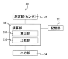
- FIG. 3A is a block diagram showing a configuration of a temperature measuring device according to the first embodiment of the present invention.
- FIG. 3B is a diagram showing a configuration of a measuring unit in the temperature measuring device according to the first embodiment of the present invention.
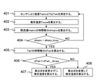
- FIG. 4 is a flowchart of the temperature measuring method according to the first embodiment of the present invention.
- FIG. 5 is a diagram showing an example of the temperature measuring method according to the first embodiment of the present invention.
- FIG. 6 is a diagram showing a configuration example of a computer according to an embodiment of the present invention.
- FIG. 7 is a schematic diagram of a pseudo one-dimensional model in a conventional temperature measurement inside a living body.
- FIG. 8 is a diagram showing changes over time in the deep temperature measured by the conventional method.
- FIG. 1 is a schematic diagram of a change over time in temperature for explaining the method according to the present embodiment.
- FIG. 1 is based on FIG. 8 described above, and shows a temperature change when a wind is applied.
- the solid line 11 shows the true internal temperature
- the dotted line 12 shows the estimated temperature Tcore calculated by the equation (1).
- Tcore Tskin + Rbody x Hskin (1)
- Hskin is a heat flux
- Hskin (Tskin-Tt) / Rs, and is calculated from the difference between Tskin and Tt.
- Tskin is the temperature near the front surface (for example, the surface in contact with the living body) of the sensor
- Tt is the temperature near the back surface (for example, the surface in contact with the outside air) of the sensor
- Rbody is the thermal resistance of the living body
- Rs is the sensor. The thermal resistance of.
- the estimated temperature 12 has an error as compared with the internal temperature 11, it is necessary to correct the estimated temperature 12 including this error in order to calculate an accurate estimated temperature.
- the change in the estimated temperature 12 is gradual because it depends on the heat capacity of the living body and the sensor. Therefore, it is difficult to correct the estimated temperature 12 by detecting the heat transport mode from the change in the estimated temperature 12. Therefore, in the present embodiment, the change in the heat transport mode is detected by using the time derivative dHskin of the heat flux Hskin, and the error at the estimated temperature 12 is corrected.
- FIG. 2 shows the time derivative dHskin of the heat flux Hskin with respect to the time course of the temperature shown in FIG. Unlike the change in the estimated temperature, the time derivative dHskin changes sharply when the heat transport mode changes and expresses steep peaks 21 and 22, so that it becomes easy to specify the time.
- the estimated temperature Tcore can be corrected and calculated by the following formula.
- Tcore Tskin + ⁇ x Rbody x Hskin (2)
- thermometer for measuring the external temperature is further provided, and the time differential dTair of the measured temperature Tair by this thermometer is used to determine whether the change in dHskin is due to the convection change. , Determine if it is due to a change in external temperature. Details will be described below.
- FIG. 3A shows a block diagram of the configuration of the temperature measuring device 30 according to the present embodiment.
- the temperature measuring device 30 includes a measuring unit (sensor) 31, a storage unit 32, a calculation unit 33, and an output unit 34.
- FIG. 3B shows the configuration of the measuring unit 31 in the temperature measuring device 30.
- the measuring unit 31 includes a sensor 311 having a first thermometer element 3111, a second thermometer element 3112, and a sensor covering unit 312 having a third thermometer element 3121.
- the first thermometer element 3111 is arranged near the surface in contact with the surface of the object to be measured (for example, a living body), and measures the temperature Tskin (first temperature) near the surface of the sensor 311. .. Further, the second thermometer element 3112 measures the temperature Tt (second temperature) in the vicinity of the back surface (the surface facing the front surface) of the sensor 311.
- the place where the temperature Tt is measured is not limited to the vicinity of the back surface of the measuring unit 31, and may be a place different from the place where the temperature Tskin is measured, that is, the place where the temperature Tskin is measured, that is, the first thermometer element 3111. It is desirable to be away from.
- the second thermometer element 3112 may be arranged at a position far enough away from the first temperature and the second temperature so that the heat flux can be accurately calculated.
- the sensor covering portion 312 is made of a material such as a mesh having good air permeability and does not interfere with convection.
- a material such as mesh, a mesh sheet made of cloth, a resin or a metal film having air holes in the air mesh, or the like can be used.
- thermometer element 3121 is arranged near the surface of the sensor covering portion 312 (a surface in contact with the sensor external environment such as outside air) to measure the external temperature Tair.
- thermometer elements are used, but the number is not limited to three and may be plural. It is possible to measure the heat flux more accurately by using a plurality of thermometer elements.
- the storage unit 32 stores the measurement time and the measurement temperature measured by the measurement unit 31, and stores numerical values such as a time constant, a reference value (threshold), and a correction coefficient required for temperature measurement according to the present embodiment. .. Further, the calculation unit 331 of the calculation unit 33 can store the estimated temperature calculated by the equations (1) and (2).
- the calculation unit 331 calculates the estimated temperature by the equations (1) and (2). Further, the calculation unit 331 calculates and calculates the heat flux, its time derivative, the time derivative of the external temperature, and other numerical values necessary for temperature measurement according to the present embodiment.
- the comparison unit 332 compares the time derivative dHskin of the heat flux calculated by the calculation unit 331 with the reference value. Further, the time derivative dTair of the external temperature calculated by the calculation unit 331 is compared with the reference value. In addition, the calculation formula of the estimated temperature is determined based on the result of the comparison.
- the output unit 34 outputs (displays) the estimated temperature calculated by the equations (1) and (2).
- the accurate temperature cannot be output, it is possible to output (display) a blank (state in which nothing is displayed) or the inability to measure the accurate temperature.
- FIG. 4 shows a flowchart of the temperature measuring method according to the present embodiment.
- the surface temperature of the sensor (temperature of the part in contact with the living body, the first temperature) Tskin, the back surface temperature of the sensor (second temperature) Tt, and the external temperature (third temperature) Measure the temperature (step 401).
- the estimated temperature is calculated by the formula (1) (step 402).
- the time derivative dHskin of the heat flux Hskin is calculated (step 403).
- the dHskin is calculated as the difference between the heat flux Hskins at the adjacent sampling (measurement) times.
- the interval between adjacent sampling (measurement) times is about 1 second.
- Hskin (ta) ⁇ Tskin (ta) -Tt (ta) ⁇ / Rs.
- Hskin (tb) ⁇ Tskin (tb) -Tt (tb) ⁇ / Rs. It is calculated by.
- dHskin Hskin (tb) -Hskin (ta).
- ta and tb do not have to be adjacent sampling (measurement) times, and may have a predetermined interval.
- the dHskin value is compared with the reference value (hereinafter referred to as “convection detection threshold”) dHskin_thres (step 404).
- dHskin_thres When dHskin is equal to or less than the convection detection threshold dHskin_thres (
- the convection detection threshold dHskin_thres is set to, for example, 0.02 ° C./sec.
- dTair is calculated as the difference between the external temperature Tires at adjacent sampling (measurement) times.
- dTair Tair (td) -Tair (tt).
- tc and td do not have to be adjacent sampling (measurement) times, and may have a predetermined interval.
- the dTair value is compared with the reference value (hereinafter referred to as “temperature detection threshold”) dTair_thres (step 406).
- dTair_thres When dTair exceeds the temperature detection threshold dTair_thres (
- the estimated temperature is calculated by the equation (1) in the state where the convection change does not occur, the convection state does not change, so the estimated temperature is calculated by the equation (1) even after the determination.
- the estimated temperature is calculated by the equation (2) in the state where the convection change occurs, the estimated temperature is calculated by the equation (2) even after the determination.
- the temperature detection threshold dTair_thres is, for example, 0.02 ° C./sec.
- the estimated temperature is calculated by changing the formula for calculating the estimated temperature according to the change in convection (step 408).
- the estimated temperature is calculated by the equation (1) in the state where the convection change does not occur, the start of the convection is determined, and after the determination, the estimated temperature is calculated by the equation (2). Further, when the estimated temperature is calculated by the equation (2) in the state where the convection change occurs, the end of the convection is determined. Therefore, after the determination, the estimated temperature is calculated by the equation (1).
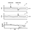
- FIG. 5 shows the time-dependent change 51 of the time derivative dHskin of the heat flux and the time-dependent change 52 of the time derivative dTair of the external temperature in the temperature measuring method according to the present embodiment.
- the time-dependent change 53 of the estimated temperature indicates the estimated temperature 531 by the temperature measuring method of the embodiment according to the present embodiment and the estimated temperature 532 by the temperature measuring method not considering the change of the external temperature as a comparative example. Further, the temperature measured by the eardrum is shown as the true internal temperature 530.
- the estimated temperature 52 is calculated by the equation (1) because no convection has occurred.
- the estimated temperature 531 calculated by the temperature measuring method of the embodiment according to the present embodiment is calculated by the equation (2) including the correction by the convection change after the time t1, and is the same temperature as the internal temperature 530. Is shown. Further, at time t2, the change in dHskin51 is due to the change in the external temperature, and the convection state does not change, that is, the convection does not end. Therefore, the estimated temperature is calculated from the equation (2) as before t2. The temperature is equivalent to the internal temperature of 530.
- the estimated temperature 532 of the comparative example after the time t1, the estimated temperature is calculated by the equation (2) including the correction by the convection change, and shows the same temperature as the internal temperature 530.
- the change in dHskin51 is due to the change in the external temperature, it is misidentified as due to the change in the convection state.
- the estimated temperature is calculated from the equation (1), so that a difference (error) from the internal temperature 530 occurs.
- the temperature measuring method it is possible to measure the temperature inside the living body with high accuracy without erroneously recognizing the convection change when the temperature change occurs.
- the generation of convection and the end of convection can be detected by measuring the change of the time derivative dHskin of the heat flux in positive and negative directions. For example, when the change in dHskin is 0 or more, the change in the morphology of heat conduction accompanying the start of convection is detected, and when the change in dHskin is less than 0, the change in the morphology of heat conduction accompanying the end of convection is detected. , The convection period can be detected.
- the calculation unit 33 sequentially uses the temperature measured by the measurement unit (sensor) 31.
- the calculated estimated temperature is output to the output unit 34.
- the calculation unit 33 determines based on the time derivative of the external temperature and determines the calculation formula.
- the estimated temperature is calculated and output to the output unit 34.
- the embodiment of the present invention does not necessarily require the storage unit 32.
- the temperature measured by the measuring unit may be collectively stored in the storage unit, and then the temperature data may be read out (read) to calculate the estimated temperature.
- the temperature measuring device according to the present embodiment may be attached to the user's body as an integral part of the wearable device.
- the measuring unit (sensor) 31 is attached to the user's body as a wearable device, and the storage unit 32 and the calculation unit 33 are stored in a smartphone or server outside the wearable device. May be provided.
- the temperature measuring device is provided with a transmission / reception unit for each of the wearable device and an external server, etc., and the measured temperature measured by the wearable device is transmitted to the server or the like, and is stored and calculated by the server or the like.
- the estimated temperature and the like may be output to the server or the like, or may be transmitted to the wearable device or the like and output.
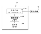
- FIG. 6 shows a configuration example of the computer 60 in the temperature measuring device according to the embodiment of the present invention.
- the temperature measuring device can be realized by a computer 60 including a CPU (Central Processing Unit) 63, a storage device (storage unit) 62, and an interface device 61, and a program for controlling these hardware resources.
- the measurement unit and the output unit are connected to the interface device.
- the CPU executes the process according to the embodiment of the present invention according to the temperature measurement program stored in the storage device. In this way, the temperature measurement program makes the temperature measurement device work.
- a computer may be provided inside the device, or at least one part of the functions of the computer may be realized by using an external computer.
- the storage unit may also use the storage medium 64 outside the apparatus, or may read out and execute the temperature measurement program stored in the storage medium 64.
- the storage medium 64 includes various magnetic recording media, optical magnetic recording media, CD-ROMs, CD-Rs, and various memories. Further, the temperature measurement program may be supplied to the computer via a communication line such as the Internet.
- the temperature inside the living body can be measured non-invasively and accurately.
- the present invention can be applied to a deep thermometer used for body temperature control of workers, athletes and the like.
Landscapes
- Physics & Mathematics (AREA)
- General Physics & Mathematics (AREA)
- Measuring And Recording Apparatus For Diagnosis (AREA)
Abstract
本発明の温度測定方法は、生体の内部の温度を、センサ(31)により検出された温度を基に測定する温度測定方法であって、外部温度の時間微分に基づいて、生体の内部の温度の推定温度の算出式を、センサ(31)における生体近傍の一の箇所の温度と他の箇所の温度との差分より算出される熱流束に基づく第1の式と、第1の式による推定温度を補正する第2の式とのいずれかに決定して、推定温度を算出する。 これにより、本発明の温度測定方法は、生体内部の温度を非侵襲に精度良く測定できる。
Description
本発明は、生体内部の温度を非侵襲に精度良く測定する温度測定装置、方法およびプログラムに関する。
従来、生体の内部(深部を含む)体温を非侵襲に測定する技術が知られている。例えば、特許文献1(特開2020-003291号公報)は、生体と、複数の温度計素子からなる熱流束センサを備える温度測定センサ(以下、「センサ」という。)と、外気とにおける疑似的な一次元モデルを仮定して、生体の深部体温を推定する技術を開示している。
図7に、生体71内部の温度測定における疑似的な一次元モデルの模式図を示す。被測定物(生体)71の内部の温度Tcoreは、被測定物(生体)71の表面に熱抵抗Rsを有する物体(センサ)を置いたとき、センサ72における表面(その物体と接する面)近傍の温度Tskin、センサ72における裏面(外気と接する側の面)近傍の温度Ttから以下の式を用いて推定できる。
Tcore = Tskin + Rbody × Hskin
ここで、Hskinは熱流束であり、Hskin=(Tskin-Tt)/Rsで表される。また、Rbodyは生体の熱抵抗、Rsはセンサの熱抵抗である。
しかしながら、この推定方法では、外気への熱の輸送形態を一定と仮定するため、扇風機などで風を当てる場合や、被測定物がランニングなどにより動く場合には推定温度に誤差が生じる。
図8に、扇風機で風を当てた時の真の内部温度81と推定温度82との比較を示す。この真の内部温度81と推定温度82の差(誤差)は、風がある閾値を超えて当てられると、熱の輸送形態が熱伝導から対流熱伝達に変化し、熱が外に伝わる量が大きく変化することに起因する。
また、対流が生じることにより熱流束Hskinはセンサの外部へも流れるため、対流時のRbodyが変化し、誤差が生じる。
このように、生体内部の温度の測定において、推定温度に誤差が生じることが問題となっている。また、推定温度の誤差において、誤差が長い時間継続すること、誤差の原因となる熱の対流時に生体の熱抵抗Rbodyが変化することが問題となる。
上述したような課題を解決するために、本発明に係る温度測定方法は、生体の内部の温度を、センサにより検出された温度を基に測定する温度測定方法であって、外部温度の時間微分に基づいて、前記生体の内部の温度の推定温度の算出式を、前記センサにおける前記生体近傍の一の箇所の温度と他の箇所の温度との差分より算出される熱流束に基づく第1の式と、前記第1の式による推定温度を補正する第2の式とのいずれかに決定して、前記推定温度を算出することを特徴とする。
また、本発明に係る温度測定方法は、生体の内部の温度を、センサにより検出された温度を基に測定する温度測定方法であって、前記センサにおいて、前記生体に接触する面近傍の第1の温度を測定し、前記第1の温度が測定される位置と異なる位置で第2の温度を測定し、センサ被覆部の表面近傍で外部温度を測定するステップと、前記第1の温度と前記第2の温度の差を基に熱流束を算出するステップと、前記熱流束の時間微分を算出するステップと、前記熱流束の時間微分が対流検出閾値を超える場合に、前記外部温度の時間微分を算出するステップと、前記外部温度の時間微分を温度検出閾値と比較することにより、前記生体の内部の温度の推定温度の算出式を決定するステップとを備え、前記推定温度の算出式が、前記熱流束に基づく第1の式と、前記第1の式による推定温度を補正する第2の式とのいずれかであることを特徴とする。
また、本発明に係る温度測定装置は、生体の内部の温度を、センサにより検出された温度を基に測定する温度測定装置であって、前記生体に接触する面近傍に配置され、第1の温度を測定する第1の温度計素子と、第1の温度計素子から離れた位置に配置され、第2の温度を測定する第2の温度計素子とを有する前記センサと、前記センサの被覆部に配置され、外部温度を測定する第3の温度計素子と、前記外部温度の時間微分に基づいて、前記生体の内部の温度の推定温度の算出式を、前記第1の温度と前記第2の温度との差分より算出される熱流束に基づく第1の式と、前記第1の式による推定温度を補正する第2の式とのいずれかに決定して、前記推定温度を算出する演算部とを備える。
また、本発明に係る温度測定プログラムは、生体の内部の温度を、センサにより検出された温度を基に測定する温度測定装置に対し、外部温度の時間微分に基づいて、前記生体の内部の温度の推定温度の算出式を、前記センサにおける前記生体近傍の一の箇所の温度と他の箇所の温度との差分より算出される熱流束に基づく第1の式と、前記第1の式による推定温度を補正する第2の式とのいずれかに決定して、前記推定温度を算出する処理を実行させることを特徴とし、温度測定装置を機能させる。
本発明によれば、生体内部の温度を非侵襲に精度良く測定する温度測定装置、方法およびプログラムを提供できる。
図1は、本実施の形態に係る方法を説明するための温度の経時変化の概要図である。図1は、前述の図8に基づくものであり、風を当てた時の温度変化を示す。実線11は真の内部温度、点線12は式(1)により算出される推定温度Tcoreを示す。
Tcore = Tskin + Rbody × Hskin(1)
ここで、Hskinは熱流束であり、Hskin=(Tskin-Tt)/Rsで表され、TskinとTtの差分より算出される。また、Tskinはセンサにおける表面(例えば、生体と接する面)近傍の温度、Ttはセンサにおける裏面(例えば、外気と接する側の面)近傍の温度であり、Rbodyは生体の熱抵抗、Rsはセンサの熱抵抗である。
風を当てたことにより、対流の開始にともなう熱輸送形態の変化が生じると、推定温度12には正のピーク(上に凸)が発現する。また、風を停止して対流の終了にともなう熱輸送形態(対流)の変化が生じると、推定温度12には負のピーク(下に凸)が発現する。
このように、推定温度12には、内部温度11に比べて、誤差が生じるので、正確な推定温度を算出するためには、この誤差を含む推定温度12を補正する必要がある。
推定温度の補正においては、まず、補正を要するとき、すなわち熱輸送形態(対流)の変化が生じるときを検知する必要がある。図1に示すように、推定温度12の変化は、生体やセンサの熱容量に依存するため、緩やかである。そこで、推定温度12の変化より熱輸送形態を検出して、推定温度12を補正することは難しい。そこで、本実施の形態においては、熱流束Hskinの時間微分dHskinを用いて熱輸送形態の変化を検出して、推定温度12における誤差を補正する。
図2に、図1に示す温度の経時変化における熱流束Hskinの時間微分dHskinを示す。推定温度の変化と異なり、時間微分dHskinは熱輸送形態が変化すると鋭敏に変化し急峻なピーク21、22を発現するので、その時刻を特定することが容易になる。
また、推定温度Tcoreは、以下の式により、補正して算出することができる。
Tcore = Tskin + α × Rbody × Hskin (2)
ここで、αは補正係数であり、1.03~1.15であることが望ましい。本実施の形形態では、α = 1.05とする。このように、式(2)は式(1)による推定温度を補正するものである。
以上のように、推定温度には対流変化により誤差が生じるため、対流変化の検知を契機に補正を行う。具体的には、熱流束Hskinの時間微分dHskinが基準値(閾値)を超えた場合に対流変化が生じたと判定して補正を行う。
しかしながら、外気温や室内温度などのセンサ外部の環境温度(以下、「外部温度」という。)が変化したときも同様に、Hskinの時間微分dHskinが閾値を超える。その結果、対流変化が生じていないにもかかわらず、対流変化が生じたものと誤認識(検知)することになる。この場合には、本来用いるべき式(1)ではなく式(2)を用いて推定温度が算出されるため、誤差が生じる。
この測定誤差を解消するために、本実施の形態では、外部温度を測定する温度計をさらに備え、この温度計による測定温度Tairの時間微分dTairを用いて、dHskinの変化が対流変化によるものか、外部温度の変化によるものかを判定する。以下に詳細を説明する。
<第1の実施の形態>
本発明の第1の実施の形態について図1~図5を参照して説明する。
本発明の第1の実施の形態について図1~図5を参照して説明する。
<温度測定装置の構成>
図3Aに、本実施の形態に係る温度測定装置30の構成のブロック図を示す。温度測定装置30は、測定部(センサ)31と、記憶部32と、演算部33と、出力部34とを備える。
図3Aに、本実施の形態に係る温度測定装置30の構成のブロック図を示す。温度測定装置30は、測定部(センサ)31と、記憶部32と、演算部33と、出力部34とを備える。
図3Bに、温度測定装置30における測定部31の構成を示す。測定部31は、第1の温度計素子3111と、第2の温度計素子3112とを有するセンサ311と、第3の温度計素子3121を有するセンサ被覆部312とを備える。
センサ311において、第1の温度計素子3111は、被測定物(例えば、生体)の表面と接触する面近傍に配置され、センサ311の表面近傍での温度Tskin(第1の温度)を測定する。また、第2の温度計素子3112は、センサ311の裏面(表面に対向する面)近傍で、温度Tt(第2の温度)を測定する。
ここで、温度Ttを測定する箇所は、測定部31の裏面近傍に限らず、温度Tskinを測定する箇所とは異なる箇所であればよく、温度Tskinを測定する箇所すなわち第1の温度計素子3111から離れた箇所であることが望ましい。第2の温度計素子3112は、第1の温度と第2の温度から正確に熱流束を算出できる程度離れた箇所に配置されればよい。
センサ被覆部312は、通気性が良いメッシュ状等の素材で構成され、対流を妨げない。
メッシュ状等の素材には、布製のメッシュシート、空気メッシュ状に空気孔の樹脂または金属膜などを用いることができる。
メッシュ状等の素材には、布製のメッシュシート、空気メッシュ状に空気孔の樹脂または金属膜などを用いることができる。
センサ被覆部312の表面(外気などのセンサ外部環境と接する面)近傍に、第3の温度計素子3121が配置され、外部温度Tairを測定する。
また、本実施の形態では、3個の温度計素子を用いるが、3個に限らず複数であればよい。複数の温度計素子を用いた方が精度よく熱流束を測定できる。
記憶部32は、測定部31で測定される測定時刻と測定温度を記憶し、本実施の形態に係る温度測定に必要な時定数、基準値(閾値)、補正係数などの数値等を記憶する。また、演算部33の算出部331で式(1)と式(2)により算出される推定温度を記憶することもできる。
演算部33において、算出部331は、式(1)と式(2)により推定温度を算出する。また、算出部331は、熱流束やその時間微分、外部温度の時間微分などの本実施の形態に係る温度測定に必要な数値等について算出、演算する。
また、比較部332は、算出部331で算出される熱流束の時間微分dHskinを基準値と比較する。また、算出部331で算出される外部温度の時間微分dTairを基準値と比較する。また、比較の結果に基づき、推定温度の算出式を決定する。
出力部34は、式(1)と式(2)により算出される推定温度を出力(表示)する。正確な温度を出力できない場合には、ブランク(何も表示しない状態)や正確な温度を測定できないことを出力(表示)することもできる。
<温度測定方法>
本実施の形態に係る方法の概要を、図4を参照して説明する。図4に、本実施の形態に係る温度測定方法のフローチャート図を示す。
本実施の形態に係る方法の概要を、図4を参照して説明する。図4に、本実施の形態に係る温度測定方法のフローチャート図を示す。
初めに、センサ(測定部)により、センサの表面温度(生体と接する部分の温度、第1の温度)Tskinと、センサの裏面温度(第2の温度)Tt、外部温度(第3の温度)Tairを測定する(ステップ401)。
次に、式(1)により、推定温度を算出する(ステップ402)。
次に、熱流束Hskinの時間微分dHskinを算出する(ステップ403)。dHskinは、隣接するサンプリング(測定)時刻での熱流束Hskinの差分として算出する。ここで、例えば、隣接するサンプリング(測定)時刻の間隔は1秒程度である。
例えば、時刻taでTskin(ta)とTt(ta)が測定されるとき、Hskin(ta)は、Hskin(ta)={Tskin(ta)-Tt(ta)}/Rsで算出される。
同様に、時刻taに引き続き、時刻tbでTskin(tb)とTt(tb)が測定されるとき、Hskin(tb)は、Hskin(tb)={Tskin(tb)-Tt(tb)}/Rsで算出される。
このとき、dHskinは、dHskin=Hskin(tb)-Hskin(ta)で算出される。
ここで、taとtbは隣接するサンプリング(測定)時刻でなくてもよく、所定の間隔を有してもよい。
次に、dHskinの値が基準値(以下、「対流検出閾値」という。)dHskin_thresを比較する(ステップ404)。
dHskinが対流検出閾値dHskin_thres以下の場合には(|dHskin|≦dHskin_thres)、対流によって熱伝達の形態が変化していないと判定して、以下のステップを行わず、上述のTcoreを、この時刻での推定温度と決定して、引き続き、次の時刻で測定を実行する。
一方、dHskinが対流検出閾値dHskin_thresを上回る場合には(|dHskin|>dHskin_thres)、このdHskinの変化が対流の変化によるものか、外部温度の変化など他の要因によるものかを、以下の通り、判定する。ここで、対流検出閾値dHskin_thresは、例えば、0.02℃/secとする。
次に、外部温度Tairの時間微分dTairを算出する(ステップ405)。dTairは、隣接するサンプリング(測定)時刻での外部温度Tairの差分として算出する。
例えば、時刻tcでTair(tc)が測定され、引き続き、時刻tdでTair(td)が測定されるとき、dTairは、dTair=Tair(td)-Tair(tc)で算出される。
ここで、tcとtdは隣接するサンプリング(測定)時刻でなくてもよく、所定の間隔を有してもよい。
次に、dTairの値が基準値(以下、「温度検出閾値」という。)dTair_thresを比較する(ステップ406)。
dTairが温度検出閾値dTair_thresを上回る場合には(|dTair|>dTair_thres)、熱流束の変化が外部温度の変化によるものであり、対流変化によるものでないと判定する。そこで、推定温度の算出式を変更することなく、推定温度を算出する(ステップ407)。
この場合、例えば、対流変化が生じていない状態で式(1)により推定温度を算出しているときには、対流状態は変化しないので、判定後も式(1)により推定温度を算出する。同様に、対流変化が生じている状態で式(2)により推定温度を算出しているときには、判定後も式(2)により推定温度を算出する。
ここで、温度検出閾値dTair_thresは、例えば、0.02℃/secとする。
一方、dTairが温度検出閾値dTair_thres以下の場合には(|dTair|≦dTair_thres)、熱流束の変化が外部温度の変化によるものでなく、対流変化によるものと判定する。そこで、対流変化にともない推定温度の算出式を変更して、推定温度を算出する(ステップ408)。
この場合、例えば、対流変化が生じていない状態で式(1)により推定温度を算出しているときには、対流の開始が判定されるので、判定後は式(2)により推定温度を算出する。また、対流変化が生じている状態で式(2)により推定温度を算出しているときには、対流の終了が判定されるので、判定後は式(1)により推定温度を算出する。
<実施例>
本実施の形態に係る温度測定方法の一例としての実施例を、図5を参照に説明する。
本実施の形態に係る温度測定方法の一例としての実施例を、図5を参照に説明する。
図5に、本実施の形態に係る温度測定方法における、熱流束の時間微分dHskinの経時変化51と外部温度の時間微分dTairの経時変化52を示す。
また、推定温度の経時変化53は、本実施の形態に係る実施例の温度測定方法による推定温度531と、比較例として、外部温度の変化を考慮しない温度測定方法による推定温度532を示す。また、真の内部温度530として、鼓膜で測定される温度を示す。
対流変化が生じていない状態から温度測定を開始する場合を一例として説明する。初めに、推定温度52は、対流が生じていないので、式(1)で算出される。
次に、時刻t1でdHskin51が基準値(閾値)511を超えるとき、外部温度の時間微分dTair52は変化しない。したがって、dHskin51の変化は対流変化によるものと判定し、算出式を変更して、式(2)により推定温度を算出する。
次に、時刻t2でdHskin51が基準値(閾値)511を超えたとき、外部温度の時間微分dTair52が変化して基準値(閾値)521を超える。したがって、dHskin51の変化は外部温度の変化によるものであり、対流変化によるものでないと判定し、算出式を変更することなく、式(2)により推定温度を算出する。
本実施の形態に係る実施例の温度測定方法により算出される推定温度531では、時刻t1以降、推定温度は対流変化による補正を含む式(2)により算出されて、内部温度530と同等の温度を示す。また、時刻t2で、dHskin51の変化が外部温度の変化によるものであり、対流状態は変化せず、すなわち、対流は終了しないので、t2以前と同様に、推定温度は式(2)より算出されて、内部温度530と同等の温度を示す。
一方、比較例の推定温度532では、時刻t1以降、推定温度は対流変化による補正を含む式(2)により算出されて、内部温度530と同等の温度を示す。しかしながら、時刻t2で、dHskin51の変化が外部温度の変化によるものであるにもかかわらず、対流状態の変化によるものと誤認される。その結果、対流が終了したものとみなされ、推定温度は式(1)より算出されるので、内部温度530と差異(誤差)が生じる。
このように、本実施の形態に係る温度測定方法によれば、気温変化発生時に対流変化の誤認識をすることなく、高精度で生体内部の温度を測定できる。
本発明に係る実施の形態では、熱流束の時間微分dHskinの変化を正負で測定することにより、対流発生と対流終了を検出できる。例えば、dHskinの変化が0以上の時に、対流開始にともなう熱伝導の形態の変化を検出して、dHskinの変化が0未満の時に、対流終了にともなう熱伝導の形態の変化を検出することにより、対流期間を検出できる。
本発明に係る実施の形態では、熱流束の時間微分の変化が検知されずに対流が生じていない場合には、測定部(センサ)31で測定された温度を基に、順次演算部33で算出される推定温度が、出力部34に出力される。
一方、熱流束の時間微分の変化が検知される場合には、測定部(センサ)31で測定された後に、演算部33で外部温度の時間微分を基に判定して算出式が決定され、推定温度が算出され、出力部34に出力される。このように、本発明に係る実施の形態では、記憶部32を必ずしも必要としない。
また、測定部(センサ)で測定された温度をまとめて記憶部に記憶してから、温度データを読み出して(読み込んで)推定温度を算出してもよい。
本実施の形態に係る温度測定装置は、ウェアラブルデバイス一体としてユーザの身体に装着されてもよい。
または、本発明に係る実施の形態に係る温度測定装置は、測定部(センサ)31をウェアラブルデバイスとしてユーザの身体に装着して、ウェアラブルデバイス外部のスマートフォンやサーバ等に記憶部32、演算部33を備えてもよい。この場合、温度測定装置はウェアラブルデバイスと外部のサーバ等それぞれに送受信部を備え、ウェアラブルデバイスで測定される測定温度をサーバ等に送信し、サーバ等で記憶、計算を行う。最後に、推定温度等(深部温度は測定されないことの表示等を含む)はサーバ等に出力されてもよいし、ウェアラブルデバイス等に送信されて出力されてもよい。
<コンピュータの構成例>
図6に、本発明の実施の形態に係る温度測定装置におけるコンピュータ60の構成例を示す。温度測定装置は、CPU(Central Processing Unit)63、記憶装置(記憶部)62およびインタフェース装置61を備えたコンピュータ60と、これらのハードウェア資源を制御するプログラムによって実現することができる。ここで、インタフェース装置に、測定部と、出力部が接続される。CPUは、記憶装置に格納された温度測定プログラムに従って本発明の実施の形態における処理を実行する。このように、温度測定プログラムは温度測定装置を機能させる。
図6に、本発明の実施の形態に係る温度測定装置におけるコンピュータ60の構成例を示す。温度測定装置は、CPU(Central Processing Unit)63、記憶装置(記憶部)62およびインタフェース装置61を備えたコンピュータ60と、これらのハードウェア資源を制御するプログラムによって実現することができる。ここで、インタフェース装置に、測定部と、出力部が接続される。CPUは、記憶装置に格納された温度測定プログラムに従って本発明の実施の形態における処理を実行する。このように、温度測定プログラムは温度測定装置を機能させる。
本発明の実施の形態に係る温度測定装置では、コンピュータを装置内部に備えてもよいし、コンピュータの機能の少なくとも1部を外部コンピュータを用いて実現してもよい。また、記憶部も装置外部の記憶媒体64を用いてもよく、記憶媒体64に格納された温度測定プログラムを読み出して実行してもよい。記憶媒体64には、各種磁気記録媒体、光磁気記録媒体、CD-ROM、CD-R、各種メモリを含む。また、温度測定プログラムはインターネットなどの通信回線を介してコンピュータに供給されてもよい。
以上のように、本実施の形態に係る温度測定装置、方法およびプログラムによれば、生体内部の温度を非侵襲に精度良く測定できる。
本発明の実施の形態では、温度測定装置の構成および温度測定方法等において、各構成部の構造、寸法、材料等の一例を示したが、これに限らない。温度測定装置の構成および温度測定方法等の機能を発揮し効果を奏するものであればよい。
本発明は、作業者、競技者等の体温管理に用いる深部温度計に適用することができる。
30 温度測定装置
31 測定部(センサ)
32 記憶部
33 演算部
331 算出部
332 比較部
34 出力部
31 測定部(センサ)
32 記憶部
33 演算部
331 算出部
332 比較部
34 出力部
Claims (8)
- 生体の内部の温度を、センサにより検出された温度を基に測定する温度測定方法であって、
外部温度の時間微分に基づいて、前記生体の内部の温度の推定温度の算出式を、前記センサにおける前記生体近傍の一の箇所の温度と他の箇所の温度との差分より算出される熱流束に基づく第1の式と、前記第1の式による推定温度を補正する第2の式とのいずれかに決定して、前記推定温度を算出する温度測定方法。 - 生体の内部の温度を、センサにより検出された温度を基に測定する温度測定方法であって、
前記センサにおいて、前記生体に接触する面近傍の第1の温度を測定し、前記第1の温度が測定される位置と異なる位置で第2の温度を測定し、センサ被覆部の表面近傍で外部温度を測定するステップと、
前記第1の温度と前記第2の温度の差を基に熱流束を算出するステップと、
前記熱流束の時間微分を算出するステップと、
前記熱流束の時間微分が対流検出閾値を超える場合に、前記外部温度の時間微分を算出するステップと、
前記外部温度の時間微分を温度検出閾値と比較することにより、前記生体の内部の温度の推定温度の算出式を決定するステップとを備え、
前記推定温度の算出式が、前記熱流束に基づく第1の式と、前記第1の式による推定温度を補正する第2の式とのいずれかである温度測定方法。 - 前記外部温度の時間微分が温度検出閾値を超える場合に、前記推定温度の算出式を変更することなく、前記推定温度が算出され、
前記外部温度の時間微分が温度検出閾値以下の場合に、前記推定温度の算出式を変更して、前記推定温度が算出される、請求項2に記載の温度測定方法。 - 前記第1の式が、
Tcore = Tskin + Rbody × (Tskin-Tt)/Rs
であり、前記第2の式が、
Tcore = Tskin + α × Rbody × (Tskin-Tt)/Rs
であり、Tskinが第1の温度であり、Ttが第2の温度であり、Rbodyは生体の熱抵抗であり、Rsはセンサの熱抵抗であり、αが補正係数である、
請求項1から請求項3のいずれか一項に記載の温度測定方法。 - 前記第2の式における補正係数が1.03以上1.15以下であることを特徴とする請求項4に記載の温度測定方法。
- 前記熱流束の時間微分が0以上のときに対流の開始にともなう熱輸送形態の変化を判定し、前記熱流束の時間微分が0より小さいときに前記対流の終了にともなう熱輸送形態の変化を判定することを特徴とする請求項1から請求項5のいずれか一項に記載の温度測定方法。
- 生体の内部の温度を、センサにより検出された温度を基に測定する温度測定装置であって、
前記生体に接触する面近傍に配置され、第1の温度を測定する第1の温度計素子と、第1の温度計素子から離れた位置に配置され、第2の温度を測定する第2の温度計素子とを有する前記センサと、
前記センサの被覆部に配置され、外部温度を測定する第3の温度計素子と、
前記外部温度の時間微分に基づいて、前記生体の内部の温度の推定温度の算出式を、前記第1の温度と前記第2の温度との差分より算出される熱流束に基づく第1の式と、前記第1の式による推定温度を補正する第2の式とのいずれかに決定して、前記推定温度を算出する演算部と
を備える温度測定装置。 - 生体の内部の温度を、センサにより検出された温度を基に測定する温度測定装置に対し、
外部温度の時間微分に基づいて、前記生体の内部の温度の推定温度の算出式を、前記センサにおける前記生体近傍の一の箇所の温度と他の箇所の温度との差分より算出される熱流束に基づく第1の式と、前記第1の式による推定温度を補正する第2の式とのいずれかに決定して、前記推定温度を算出する処理を実行させることを特徴とする、温度測定装置を機能させるための温度測定プログラム。
Priority Applications (2)
| Application Number | Priority Date | Filing Date | Title |
|---|---|---|---|
| JP2022535992A JP7420255B2 (ja) | 2020-07-13 | 2020-07-13 | 温度測定装置、方法およびプログラム |
| PCT/JP2020/027225 WO2022013912A1 (ja) | 2020-07-13 | 2020-07-13 | 温度測定装置、方法およびプログラム |
Applications Claiming Priority (1)
| Application Number | Priority Date | Filing Date | Title |
|---|---|---|---|
| PCT/JP2020/027225 WO2022013912A1 (ja) | 2020-07-13 | 2020-07-13 | 温度測定装置、方法およびプログラム |
Publications (1)
| Publication Number | Publication Date |
|---|---|
| WO2022013912A1 true WO2022013912A1 (ja) | 2022-01-20 |
Family
ID=79555230
Family Applications (1)
| Application Number | Title | Priority Date | Filing Date |
|---|---|---|---|
| PCT/JP2020/027225 Ceased WO2022013912A1 (ja) | 2020-07-13 | 2020-07-13 | 温度測定装置、方法およびプログラム |
Country Status (2)
| Country | Link |
|---|---|
| JP (1) | JP7420255B2 (ja) |
| WO (1) | WO2022013912A1 (ja) |
Citations (5)
| Publication number | Priority date | Publication date | Assignee | Title |
|---|---|---|---|---|
| JP2007212407A (ja) * | 2006-02-13 | 2007-08-23 | Kanazawa Univ | 非加熱型深部体温計およびそれを用いた深部体温測定装置 |
| US20070282218A1 (en) * | 2006-05-31 | 2007-12-06 | Medisim Ltd. | Non-invasive temperature measurement |
| JP2012154859A (ja) * | 2011-01-27 | 2012-08-16 | Terumo Corp | 体温計 |
| JP2017055968A (ja) * | 2015-09-16 | 2017-03-23 | カシオ計算機株式会社 | 温度測定装置及び温度測定方法 |
| JP2019211270A (ja) * | 2018-06-01 | 2019-12-12 | 日本電信電話株式会社 | 生体内温度測定装置および生体内温度測定方法 |
-
2020
- 2020-07-13 WO PCT/JP2020/027225 patent/WO2022013912A1/ja not_active Ceased
- 2020-07-13 JP JP2022535992A patent/JP7420255B2/ja active Active
Patent Citations (5)
| Publication number | Priority date | Publication date | Assignee | Title |
|---|---|---|---|---|
| JP2007212407A (ja) * | 2006-02-13 | 2007-08-23 | Kanazawa Univ | 非加熱型深部体温計およびそれを用いた深部体温測定装置 |
| US20070282218A1 (en) * | 2006-05-31 | 2007-12-06 | Medisim Ltd. | Non-invasive temperature measurement |
| JP2012154859A (ja) * | 2011-01-27 | 2012-08-16 | Terumo Corp | 体温計 |
| JP2017055968A (ja) * | 2015-09-16 | 2017-03-23 | カシオ計算機株式会社 | 温度測定装置及び温度測定方法 |
| JP2019211270A (ja) * | 2018-06-01 | 2019-12-12 | 日本電信電話株式会社 | 生体内温度測定装置および生体内温度測定方法 |
Also Published As
| Publication number | Publication date |
|---|---|
| JP7420255B2 (ja) | 2024-01-23 |
| JPWO2022013912A1 (ja) | 2022-01-20 |
Similar Documents
| Publication | Publication Date | Title |
|---|---|---|
| CN105245686B (zh) | 一种操作移动设备的方法和移动设备 | |
| US9702681B2 (en) | System and method for temperature compensation of measurement machine | |
| JP2019130632A (ja) | 異常判別装置、プログラム、異常判別システム及び異常判別方法 | |
| CN113405805A (zh) | 一种考虑进气道附面层的航空发动机进口流量获取方法 | |
| US20220260431A1 (en) | Temperature Measurement Method and Program | |
| WO2017211071A1 (zh) | 预测温度的方法及其装置 | |
| JPWO2021166128A5 (ja) | 異常推定装置、異常推定方法、及びプログラム | |
| JP2009505062A5 (ja) | ||
| CN109100051A (zh) | 温度传感器的动态响应的温度修正方法及装置 | |
| JP7135209B2 (ja) | 熱画像カメラを用いた温度測定装置、方法、及びコンピュータで読み出し可能な記録媒体 | |
| JP4658818B2 (ja) | 温度推定方法および装置 | |
| KR101262277B1 (ko) | 로봇의 충돌검지 방법 | |
| JP2005516222A (ja) | バイアス不安定性を有する加速度計を訂正および較正する方法およびシステム | |
| CN109340991B (zh) | 空调温度采集修正方法、装置及电子设备 | |
| CN111537076B (zh) | 一种抑制红外设备在启动阶段温度漂移的方法及系统 | |
| US12088784B2 (en) | Thermal imaging camera and shutter operation state monitoring method thereof | |
| KR102212113B1 (ko) | 전자직물 구조에서의 생체환경정보 측정 및 보정 방법 | |
| JP7420255B2 (ja) | 温度測定装置、方法およびプログラム | |
| JP2020116660A (ja) | 工作機械の熱変位補正方法及び熱変位補正装置 | |
| WO2022013911A1 (ja) | 温度測定装置、方法およびプログラム | |
| CN111551258B (zh) | 一种基于自适应加权的多红外传感器测温校正方法 | |
| CN118758441B (zh) | 基于温度传感器历史温度的变速箱温度检测方法及系统 | |
| JP7375933B2 (ja) | 温度測定装置、方法およびプログラム | |
| CN107729625A (zh) | 一种对设备运行发热造成的温度测量误差进行补偿的方法及装置 | |
| JP5190134B2 (ja) | 角速度検出方法及びその装置 |
Legal Events
| Date | Code | Title | Description |
|---|---|---|---|
| 121 | Ep: the epo has been informed by wipo that ep was designated in this application |
Ref document number: 20945625 Country of ref document: EP Kind code of ref document: A1 |
|
| ENP | Entry into the national phase |
Ref document number: 2022535992 Country of ref document: JP Kind code of ref document: A |
|
| NENP | Non-entry into the national phase |
Ref country code: DE |
|
| 122 | Ep: pct application non-entry in european phase |
Ref document number: 20945625 Country of ref document: EP Kind code of ref document: A1 |