WO2022012213A1 - 一种剔除一比特信号谐波虚假目标的方法及相关组件 - Google Patents
一种剔除一比特信号谐波虚假目标的方法及相关组件 Download PDFInfo
- Publication number
- WO2022012213A1 WO2022012213A1 PCT/CN2021/098573 CN2021098573W WO2022012213A1 WO 2022012213 A1 WO2022012213 A1 WO 2022012213A1 CN 2021098573 W CN2021098573 W CN 2021098573W WO 2022012213 A1 WO2022012213 A1 WO 2022012213A1
- Authority
- WO
- WIPO (PCT)
- Prior art keywords
- angle
- distance
- signal
- slope
- target
- Prior art date
- Legal status (The legal status is an assumption and is not a legal conclusion. Google has not performed a legal analysis and makes no representation as to the accuracy of the status listed.)
- Ceased
Links
Images




Classifications
-
- G—PHYSICS
- G01—MEASURING; TESTING
- G01S—RADIO DIRECTION-FINDING; RADIO NAVIGATION; DETERMINING DISTANCE OR VELOCITY BY USE OF RADIO WAVES; LOCATING OR PRESENCE-DETECTING BY USE OF THE REFLECTION OR RERADIATION OF RADIO WAVES; ANALOGOUS ARRANGEMENTS USING OTHER WAVES
- G01S7/00—Details of systems according to groups G01S13/00, G01S15/00, G01S17/00
- G01S7/02—Details of systems according to groups G01S13/00, G01S15/00, G01S17/00 of systems according to group G01S13/00
- G01S7/41—Details of systems according to groups G01S13/00, G01S15/00, G01S17/00 of systems according to group G01S13/00 using analysis of echo signal for target characterisation; Target signature; Target cross-section
- G01S7/414—Discriminating targets with respect to background clutter
-
- G—PHYSICS
- G01—MEASURING; TESTING
- G01S—RADIO DIRECTION-FINDING; RADIO NAVIGATION; DETERMINING DISTANCE OR VELOCITY BY USE OF RADIO WAVES; LOCATING OR PRESENCE-DETECTING BY USE OF THE REFLECTION OR RERADIATION OF RADIO WAVES; ANALOGOUS ARRANGEMENTS USING OTHER WAVES
- G01S7/00—Details of systems according to groups G01S13/00, G01S15/00, G01S17/00
- G01S7/02—Details of systems according to groups G01S13/00, G01S15/00, G01S17/00 of systems according to group G01S13/00
- G01S7/35—Details of non-pulse systems
- G01S7/352—Receivers
- G01S7/354—Extracting wanted echo-signals
-
- G—PHYSICS
- G01—MEASURING; TESTING
- G01S—RADIO DIRECTION-FINDING; RADIO NAVIGATION; DETERMINING DISTANCE OR VELOCITY BY USE OF RADIO WAVES; LOCATING OR PRESENCE-DETECTING BY USE OF THE REFLECTION OR RERADIATION OF RADIO WAVES; ANALOGOUS ARRANGEMENTS USING OTHER WAVES
- G01S13/00—Systems using the reflection or reradiation of radio waves, e.g. radar systems; Analogous systems using reflection or reradiation of waves whose nature or wavelength is irrelevant or unspecified
- G01S13/02—Systems using reflection of radio waves, e.g. primary radar systems; Analogous systems
- G01S13/06—Systems determining position data of a target
- G01S13/08—Systems for measuring distance only
- G01S13/32—Systems for measuring distance only using transmission of continuous waves, whether amplitude-, frequency-, or phase-modulated, or unmodulated
- G01S13/34—Systems for measuring distance only using transmission of continuous waves, whether amplitude-, frequency-, or phase-modulated, or unmodulated using transmission of continuous, frequency-modulated waves while heterodyning the received signal, or a signal derived therefrom, with a locally-generated signal related to the contemporaneously transmitted signal
- G01S13/343—Systems for measuring distance only using transmission of continuous waves, whether amplitude-, frequency-, or phase-modulated, or unmodulated using transmission of continuous, frequency-modulated waves while heterodyning the received signal, or a signal derived therefrom, with a locally-generated signal related to the contemporaneously transmitted signal using sawtooth modulation
-
- G—PHYSICS
- G01—MEASURING; TESTING
- G01S—RADIO DIRECTION-FINDING; RADIO NAVIGATION; DETERMINING DISTANCE OR VELOCITY BY USE OF RADIO WAVES; LOCATING OR PRESENCE-DETECTING BY USE OF THE REFLECTION OR RERADIATION OF RADIO WAVES; ANALOGOUS ARRANGEMENTS USING OTHER WAVES
- G01S7/00—Details of systems according to groups G01S13/00, G01S15/00, G01S17/00
- G01S7/02—Details of systems according to groups G01S13/00, G01S15/00, G01S17/00 of systems according to group G01S13/00
- G01S7/35—Details of non-pulse systems
- G01S7/352—Receivers
- G01S7/356—Receivers involving particularities of FFT processing
-
- G—PHYSICS
- G01—MEASURING; TESTING
- G01S—RADIO DIRECTION-FINDING; RADIO NAVIGATION; DETERMINING DISTANCE OR VELOCITY BY USE OF RADIO WAVES; LOCATING OR PRESENCE-DETECTING BY USE OF THE REFLECTION OR RERADIATION OF RADIO WAVES; ANALOGOUS ARRANGEMENTS USING OTHER WAVES
- G01S7/00—Details of systems according to groups G01S13/00, G01S15/00, G01S17/00
- G01S7/02—Details of systems according to groups G01S13/00, G01S15/00, G01S17/00 of systems according to group G01S13/00
- G01S7/41—Details of systems according to groups G01S13/00, G01S15/00, G01S17/00 of systems according to group G01S13/00 using analysis of echo signal for target characterisation; Target signature; Target cross-section
- G01S7/411—Identification of targets based on measurements of radar reflectivity
-
- G—PHYSICS
- G01—MEASURING; TESTING
- G01S—RADIO DIRECTION-FINDING; RADIO NAVIGATION; DETERMINING DISTANCE OR VELOCITY BY USE OF RADIO WAVES; LOCATING OR PRESENCE-DETECTING BY USE OF THE REFLECTION OR RERADIATION OF RADIO WAVES; ANALOGOUS ARRANGEMENTS USING OTHER WAVES
- G01S7/00—Details of systems according to groups G01S13/00, G01S15/00, G01S17/00
- G01S7/02—Details of systems according to groups G01S13/00, G01S15/00, G01S17/00 of systems according to group G01S13/00
- G01S7/41—Details of systems according to groups G01S13/00, G01S15/00, G01S17/00 of systems according to group G01S13/00 using analysis of echo signal for target characterisation; Target signature; Target cross-section
- G01S7/418—Theoretical aspects
-
- Y—GENERAL TAGGING OF NEW TECHNOLOGICAL DEVELOPMENTS; GENERAL TAGGING OF CROSS-SECTIONAL TECHNOLOGIES SPANNING OVER SEVERAL SECTIONS OF THE IPC; TECHNICAL SUBJECTS COVERED BY FORMER USPC CROSS-REFERENCE ART COLLECTIONS [XRACs] AND DIGESTS
- Y02—TECHNOLOGIES OR APPLICATIONS FOR MITIGATION OR ADAPTATION AGAINST CLIMATE CHANGE
- Y02A—TECHNOLOGIES FOR ADAPTATION TO CLIMATE CHANGE
- Y02A90/00—Technologies having an indirect contribution to adaptation to climate change
- Y02A90/10—Information and communication technologies [ICT] supporting adaptation to climate change, e.g. for weather forecasting or climate simulation
Definitions
- the invention relates to the application fields of data acquisition and radar systems, in particular to a method and related components for eliminating a one-bit signal harmonic false target.
- Millimeter-wave array radar has all-weather, all-weather, long-range, high-resolution detection capabilities, and plays an important role in many fields such as assisted driving, target detection, UAV altitude determination and obstacle avoidance.
- the burden of data acquisition, transmission and processing is also increasing; on the one hand, the array radar system needs to perform high-precision sampling on the echo data to retain Complete signal characteristics, which leads to an increase in the data processing bit width, which puts forward higher requirements for the hardware performance of the system; on the other hand, the signal sampling rate also needs to be increased accordingly to avoid aliasing of the signal spectrum, thus increasing the amount of data. increase, reducing the efficiency of data processing.
- the purpose of the present invention is to provide a method for eliminating one-bit signal harmonic false targets and related components, aiming to solve the problem that when the prior art performs one-bit quantization sampling on radar echo data, the false targets of the introduced harmonic components cause radar damage.
- Signal processing is complex and affects the detection effect.
- an embodiment of the present invention provides a method for rejecting a one-bit signal harmonic spurious target, which includes:
- an embodiment of the present invention provides a device for rejecting a one-bit signal harmonic spurious target, which includes:
- an acquisition unit configured to acquire the echo signal of the detected target detected by the array radar and perform de-slope processing on the echo signal to obtain the de-slope echo signal;
- the sampling unit is used to perform frequency-shift processing on the de-slope echo signal and perform one-bit quantization on the de-slope echo signal after the frequency-shift processing, and then perform AD data acquisition to obtain the de-slope signal data;
- the Fourier transform unit is used to perform Fourier transform on the de-slope signal data to obtain the frequency spectrum
- the detection unit is used to normalize the amplitude of the spectrum of each channel and obtain the amplitude value, and then perform constant false alarm rate detection to obtain the distance of the real target and the distance of the false target, and calculate the distance of the real target and the distance of the false target.
- the corresponding sampling points are saved; the sampling points without repetition are filtered out and the distance-channel data block is constructed;
- a first estimation unit configured to perform smooth forward and backward spatial angle-of-arrival estimation on a single snapshot corresponding to each sampling point of the distance-channel data block, and obtain angle-of-arrival information based on the single snapshot;
- the second estimation unit is used for sampling the one-bit quantized de-slope signal data of each channel to obtain the multi-snapshots, and to estimate the forward and backward spatial smoothing angle of arrival for all the multi-snapshots, to obtain the multi-snapshot-based angle of arrival information;
- the difference comparison unit is used to make a difference comparison between the angle of arrival information based on the single snapshot and the angle of arrival information based on multiple snapshots, and select the angle with the smallest angle difference from the angle of arrival information based on the single snapshot the corresponding distance, and take this distance as the distance of the real target.
- an embodiment of the present invention further provides a computer device, which includes a memory, a processor, and a computer program stored on the memory and executable on the processor, where the processor executes the computer During the program, the method for eliminating the false target of one-bit signal harmonics described in the first aspect is realized.
- an embodiment of the present invention further provides a computer-readable storage medium, wherein the computer-readable storage medium stores a computer program, and when executed by a processor, the computer program causes the processor to execute the above-mentioned first step.
- the method for eliminating false targets of one-bit signal harmonics is described.
- the invention discloses a method and related components for eliminating a one-bit signal harmonic false target.
- the method obtains the spectrum by de-slope, frequency shift, one-bit quantization, AD sampling and Fourier transform processing of the echo signal, and then performs constant false alarm rate detection on the spectrum to obtain the distance of the real target and the false target.
- the angle difference obtained from the angle of arrival information based on a single snapshot is the smallest.
- the distance corresponding to the angle is taken as the distance of the real target, and the false target is eliminated.
- the embodiment of the present invention realizes data collection with a lower sampling rate, greatly reduces the amount of data, simplifies the structure of the radar system, reduces the complexity of the system, and reduces the cost of data collection, transmission, storage and processing.
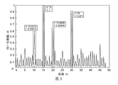
- Fig. 1 is the schematic diagram of one-bit quantized sampling LFMCW de-slope pulse compressed signal spectrum in the prior art
- FIG. 2 is a schematic flowchart of a method for eliminating a one-bit signal harmonic false target provided by an embodiment of the present invention
- FIG. 3 is a schematic sub-flow diagram of a method for eliminating a one-bit signal harmonic false target provided by an embodiment of the present invention
- FIG. 4 is a schematic diagram of another sub-flow of a method for eliminating a one-bit signal harmonic false target provided by an embodiment of the present invention.
- FIG. 5 is a schematic diagram of a de-slope processing process provided by an embodiment of the present invention.
- Fig. 6 is the principle block diagram of eliminating one-bit signal harmonic false target provided by the embodiment of the present invention.
- FIG. 7 is a schematic diagram of a spectral constant false alarm rate detection result of a one-bit quantized sampling de-slope echo signal provided by an embodiment of the present invention.
- FIG. 9 is a schematic diagram of a distance-channel data block after rearrangement of constant false alarm detection provided by an embodiment of the present invention.
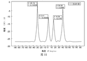
- FIG. 11 is a schematic diagram of an angle of arrival estimation result obtained based on multiple snapshots according to an embodiment of the present invention.
- FIG. 13 is a polar coordinate diagram of a real target distance-angle provided by an embodiment of the present invention.
- FIG. 14 is a schematic diagram of a signal model of a uniform linear array provided by an embodiment of the present invention.
- FIG. 15 is a schematic diagram of forward and backward space smoothing provided by an embodiment of the present invention.
- FIG. 16 is a schematic block diagram of an apparatus for removing a false target of harmonics from a one-bit signal provided by an embodiment of the present invention.
- FIG. 17 is a schematic block diagram of a computer device according to an embodiment of the present invention.
- FIG. 2 is a flowchart of a method for eliminating a one-bit signal harmonic false target provided by an embodiment of the present invention
- the method includes steps S201-S207.
- the array radar transmits a chirp signal to the detected target through the antenna, the pulse signal propagates to the detected target, the detected target reflects the echo signal, and is received by the array radar system. Then, the echo signal is de-skewed to realize pulse compression, which can make the array radar system choose a lower sampling frequency and avoid using high-precision, high-speed ADC (analog-to-digital converter).
- step S201 includes:
- the echo signal is de-skewed according to the following formula:
- S r1 (t) is the echo signal reflected by the detected target after the time delay ⁇ ;
- S Ref (t) is the reference signal of the same type as S r1 (t);
- S IF (t) is the de-slope echo signal;
- a 1 is the maximum amplitude value of the echo signal;
- a 2 is the maximum amplitude value of the reference signal;
- ⁇ is the echo signal relative to the transmitted signal Time delay, ⁇ 0 is the time delay of the reference signal relative to the transmitted signal;
- f 0 is the center frequency;
- the de-slope processing process takes the first receiving channel of the uniform linear array of the array radar as an example.
- S202 Perform frequency-shift processing on the de-slope echo signal, perform one-bit quantization on the de-slope echo signal after the frequency-shift processing, and then perform AD data collection to obtain de-slope signal data.
- the de-slope echo signal is first subjected to frequency-shift processing, and the frequency band of the de-slope echo signal is separated from the higher harmonics to obtain a result that does not contain higher-order harmonics.
- step S202 includes:
- S 1b (t) sign[real(S IF (t)]+jsign[imag(S IF (t)]; wherein, S 1b (t) is the de-slope signal data.
- the process of one-bit quantization is the part of sign( ⁇ ) in FIG. 6 .
- one-bit quantization is performed on the de-slope echo signal to obtain the de-slope signal data.
- the fast time dimension of the de-slope signal data is transformed into the frequency domain through Fourier transform to obtain a frequency spectrum.
- step S203 includes:
- the resolution of the narrow pulse in the frequency domain is obtained as 1/T p , and the relationship between the distance resolution and the frequency resolution:
- ⁇ f is the frequency resolution
- ⁇ R is the distance resolution
- k is the frequency modulation slope of the transmitted signal
- c is the electromagnetic wave propagation speed
- B represents the LFMCW signal (ie the transmit signal or the reference signal).
- the constant false alarm rate detection is carried out, and the clutter with the smaller amplitude is eliminated, leaving the distance of the real target and the distance of the false target;
- the black circle in Figure 7 is the target point left by the detection, and the sampling point corresponding to its distance is saved; since the sampling points saved by multiple channels are duplicated, the sampling points without duplicates on multiple channels are recorded and saved as distance- Channel data block.
- step S204 includes:
- S402 perform constant false alarm rate detection on the spectrum of each channel according to the amplitude value, record the detected frequency spectrum line number of the detected target, then remove the repeated spectrum line number, and compare the remaining spectrum lines with the spectrum lines
- the sampling points of the corresponding multiple channels constitute a distance-channel data block.
- the constant false alarm processing is performed on the spectral data of each channel in a one-dimensional space
- the principle of the constant false alarm rate detection is: the detection of the spectral line x n before and after the detection 8 spectral lines, of which the spectral line numbers x n-2 to x n-1 and the four spectral lines of the spectral line numbers x n+1 to x n+2 are used as protection units, and the spectral line numbers x n-8 to x n -3 and the 12 spectral lines from the spectral line numbers x n+2 to x n+8 are used as training units; the spectral lines of these 12 training units are accumulated to take the average value Z, and multiplied by the threshold coefficient ⁇ of CFAR, Among them, ⁇ is determined by the constant false alarm rate, which can be adjusted in the system; then Z is compared with x n , if x n > ⁇ Z, it is judged that the
- the clutter with smaller amplitude is eliminated, and the repeated spectral line number is eliminated, and then the spectral lines corresponding to the remaining spectral line numbers and the multiple channels corresponding to the spectral lines are removed.
- the sample points form the distance-channel data block (as shown in Figure 9).
- S205 Perform forward and backward spatial smoothing angle-of-arrival estimation on the single snapshot corresponding to each sampling point of the distance-channel data block to obtain angle-of-arrival information based on the single snapshot.
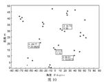
- the angle of arrival of a single snapshot based on spatial smoothing is estimated for each sampling point of the distance-channel data block one by one, and the angle of arrival information based on a single snapshot is obtained, and then the angle is the abscissa and the distance is The ordinate draws an angle-distance point diagram (as shown in Figure 10).
- S206 Sampling the one-bit quantized de-slope signal data of each channel to obtain multi-snapshots, and perform forward and backward spatially smoothed angle-of-arrival estimation for all the multi-snapshots to obtain the multi-snapshot-based angle of arrival information.
- the one-bit quantized de-slope signal data of each channel is sampled, and there are 16 channels here, and the forward and backward spatial smoothing angle of arrival is performed by using the multi-snapshots of the one-bit quantized sampling of 16 channels. Estimate, and obtain the DOA information based on how many snapshots are taken (as shown in Figure 11).
- step S206 includes:
- a M D q-1 R s (D q-1 ) H A M H represents the covariance matrix of the echo signal (except noise) as a whole, A M represents the direction matrix of the sub-array, and D q-1 represents the diagonal The q-1 power operation of matrix D, where the expression of D is: A M H represents the conjugate transpose of A M;
- ⁇ 2 I represents the covariance matrix of the noise as a whole
- ⁇ 2 represents the auto-covariance of the echo signal noise (here refers to the auto-covariance of the noise signal)
- ⁇ represents the variance
- I represents the identity matrix
- the decomposed eigenvectors are then divided into signal subspace and noise subspace according to the following formula:
- the spatial spectral function is constructed according to the orthogonal relationship between the noise subspace and the array response matrix, and the peak search of the spatial spectral function is carried out to obtain the angle of arrival information based on the multiple snapshots.
- step S207 includes:
- the difference is calculated according to the following formula, and the angle with the smallest angle difference is obtained from the angle of arrival information based on the single snapshot:
- Angle1 is the angle of arrival information based on multiple snapshots
- Angle2 is the angle of arrival information based on a single snapshot
- M is the number of angles in the angle of arrival information based on multiple snapshots
- N is the angle of arrival information based on a single snapshot The number of angles in the angle information.
- the distance corresponding to the angle with the smallest angle difference in the angle of arrival information based on the single snapshot is taken as the distance of the real target.
- the angles in Angle2 are taken out one by one and compared with all the angles in Angle1 to make a difference in turn, and the distance corresponding to the angle in Angle2 with the smallest angle difference (that is, the angle in FIG. 10 ) (the angle in FIG. 10 )
- the ordinate distance) is selected, which is the distance of the real target (as shown in Figure 12); thus eliminating the harmonics on the harmonics of the distance dimension, and finally obtaining the polar coordinates of the distance and angle of the real target (as shown in Figure 13) ).
- the embodiment of the present invention obtains the angle of arrival information based on the single snapshot and the angle of arrival information based on the multi-snap by respectively performing forward and backward spatially smoothed angle-of-arrival estimation on the single snapshot of the distance-channel data block and the multiple snapshots of each channel.
- the angle of arrival information; the method of spatially smoothing the angle of arrival used here is realized by using the signal model of the uniform linear array.
- a signal model for the estimation of the spatially smoothed angle of arrival is constructed.
- the total received signal X(t) of all the array elements of the uniform linear array can be expressed as:
- M represents the number of uniform array elements
- N represents the number of snapshots
- K represents the number of sources (detected targets), where the requirement for the number of sources is K ⁇ M
- X is the output of the array element
- A is the corresponding matrix of the array
- S is the incident signal
- N is the array noise
- the array response matrix of a uniform linear array with element spacing d is:
- the covariance matrix of the h-th forward subarray is:
- the symbol f represents the forward direction
- the forward space smoothing covariance matrix is defined as:
- the symbol b represents backward
- the backward spatial smoothing covariance matrix is defined as:
- R b and R f are conjugate inverse order matrix
- R b and R f there is a conjugate inverse order invariance between R b and R f , so the forward and backward smooth covariance matrix can be defined as:
- the embodiment of the present invention adopts forward and backward spatial smoothing, not just forward or backward, just to take advantage of the conjugate flashback invariance: the number of sub-arrays can be increased, thereby improving the accuracy of angle of arrival estimation.
- R U ⁇ U H ;
- diag represents the diagonal matrix
- ⁇ 2 represents the noise power of white Gaussian noise
- the eigenvectors U 1 , U 2 , ..., U K corresponding to the largest eigenvalue ⁇ equal to the number of signals K constitute the signal subspace U S ; the remaining (MK) eigenvalues correspond to The eigenvectors U K+1 , U K+2 ,..., U M constitute the noise subspace U N , the eigenvalue decomposition process is as follows:
- ⁇ S diag( ⁇ 1 , ⁇ 2 ,..., ⁇ K );
- ⁇ N diag( ⁇ K+1 , ⁇ K+2 ,..., ⁇ M );
- ⁇ S is a diagonal matrix composed of K larger eigenvalues
- ⁇ N is a diagonal matrix composed of MK eigenvalues
- An embodiment of the present invention further provides a device for removing a false target of harmonics from a one-bit signal, and the device for removing a false target for harmonics from a one-bit signal is used to perform any embodiment of the foregoing method for removing a false target for harmonics from a one-bit signal.
- FIG. 16 is a schematic block diagram of an apparatus for eliminating false targets of harmonics from a one-bit signal provided by an embodiment of the present invention.
- the device 1600 for eliminating the false target of one-bit signal harmonics includes: an acquisition unit 1601 , a sampling unit 1602 , a Fourier transform unit 1603 , a detection unit 1604 , a first estimation unit 1605 , and a second estimation unit 1606 And the difference comparison unit 1607 .
- an acquisition unit 1601, configured to acquire the echo signal of the detected target detected by the array radar and perform de-slope processing on the echo signal to obtain the de-slope echo signal;
- Sampling unit 1602 is used to perform frequency-shift processing on the de-slope echo signal and perform one-bit quantization on the de-slope echo signal after the frequency-shift processing, and then perform AD data collection to obtain the de-slope signal data;
- Fourier transform unit 1603 for performing Fourier transform on the de-slope signal data to obtain a frequency spectrum
- the detection unit 1604 is used to obtain the normalized amplitude of the spectrum of each channel and obtain the amplitude value, and then performs constant false alarm rate detection to obtain the distance of the real target and the distance of the false target, and compares the distance of the real target and the false target. Save the sampling points corresponding to the distance; filter out the sampling points without repetition and construct the distance-channel data block;
- the first estimation unit 1605 is used for performing forward and backward spatial smoothing angle of arrival estimation on the single snapshot corresponding to each sampling point of the distance-channel data block, to obtain the angle of arrival information based on the single snapshot;
- the second estimating unit 1606 is configured to sample the one-bit quantized de-slope signal data of each channel to obtain multi-snapshots, and to estimate the forward and backward spatial smoothing angle of arrival for all the multi-snapshots, to obtain the multi-snapshot-based angle of arrival. the angle of arrival information;
- the difference comparison unit 1607 is configured to perform a difference comparison between the angle of arrival information based on the single snapshot and the angle of arrival information based on multiple snapshots, and select the one with the smallest angle difference from the angle of arrival information based on the single snapshot.
- the distance corresponding to the angle is taken as the distance of the real target.
- the device realizes data collection with a lower sampling rate, greatly reduces the amount of data, and achieves the purpose of simplifying the structure of the radar system, reducing the complexity of the system, and reducing the cost of data collection, transmission, storage and processing.
- the above-mentioned apparatus for eliminating false targets of harmonics of a one-bit signal can be implemented in the form of a computer program, and the computer program can be executed on a computer device as shown in FIG. 17 .
- FIG. 17 is a schematic block diagram of a computer device provided by an embodiment of the present invention.
- the computer device 1700 is a server, and the server may be an independent server or a server cluster composed of multiple servers.
- the computer device 1700 includes a processor 1702 , a memory and a network interface 1705 connected by a system bus 1701 , wherein the memory may include a non-volatile storage medium 1703 and an internal memory 1704 .
- the nonvolatile storage medium 1703 can store an operating system 17031 and a computer program 17032 .
- the computer program 17032 when executed, can cause the processor 1702 to perform a method of rejecting one-bit signal harmonic spurious objects.
- the processor 1702 is used to provide computing and control capabilities to support the operation of the entire computer device 1700 .
- the internal memory 1704 provides an environment for the execution of the computer program 17032 in the non-volatile storage medium 1703.
- the computer program 17032 can cause the processor 1702 to execute a method for eliminating spurious objects of one-bit signal harmonics.
- the network interface 1705 is used for network communication, such as providing transmission of data information.
- the network interface 1705 is used for network communication, such as providing transmission of data information.
- FIG. 17 is only a block diagram of a part of the structure related to the solution of the present invention, and does not constitute a limitation on the computer device 1700 to which the solution of the present invention is applied.
- the specific computer device 1700 may include more or fewer components than shown, or combine certain components, or have a different arrangement of components.
- the embodiment of the computer device shown in FIG. 17 does not constitute a limitation on the specific structure of the computer device.
- the computer device may include more or less components than those shown in the drawings. Either some components are combined, or different component arrangements.
- the computer device may only include a memory and a processor. In such an embodiment, the structures and functions of the memory and the processor are the same as those of the embodiment shown in FIG. 17 , and details are not repeated here.
- the processor 1702 may be a central processing unit (Central Processing Unit, CPU), and the processor 1702 may also be other general-purpose processors, digital signal processors (Digital Signal Processor, DSP), Application Specific Integrated Circuit (ASIC), Field-Programmable Gate Array (FPGA) or other programmable logic devices, discrete gate or transistor logic devices, discrete hardware components, etc.
- the general-purpose processor can be a microprocessor or the processor can also be any conventional processor or the like.
- a computer-readable storage medium may be a non-volatile computer-readable storage medium.
- the computer-readable storage medium stores a computer program, wherein when the computer program is executed by the processor, the method for eliminating the spurious target of one-bit signal harmonics according to the embodiment of the present invention is implemented.
- the storage medium is a physical, non-transitory storage medium, such as a U disk, a removable hard disk, a read-only memory (Read-Only Memory, ROM), a magnetic disk or an optical disk and other physical storage that can store program codes. medium.
- ROM Read-Only Memory
Landscapes
- Engineering & Computer Science (AREA)
- Radar, Positioning & Navigation (AREA)
- Remote Sensing (AREA)
- Computer Networks & Wireless Communication (AREA)
- Physics & Mathematics (AREA)
- General Physics & Mathematics (AREA)
- Radar Systems Or Details Thereof (AREA)
Abstract
一种剔除一比特信号谐波虚假目标的方法及相关组件,其中,方法通过对回波信号进行去斜、频移、一比特量化、AD采样以及傅里叶变换处理后得到频谱,再对频谱进行恒虚警率检测,得到真实目标的距离和虚假目标的距离,针对虚假目标的距离,通过基于多快拍的波达角度信息与基于单快拍的波达角度信息进行作差比较,从基于单快拍的波达角度信息中的得到角度差最小的角度所对应的距离,并将距离作为真实目标的距离(S207),进而消除虚假目标;采用更低的采样率进行数据采集,大幅降低数据量,达到了简化雷达系统结构,降低系统复杂度,降低数据采集、传输、存储和处理的成本的目的。
Description
本发明涉及数据采集和雷达系统应用领域,尤其涉及一种剔除一比特信号谐波虚假目标的方法及相关组件。
毫米波阵列雷达具有全天时、全天候、远作用距离、高分辨的探测能力,在辅助驾驶、目标检测、无人机定高与避障等众多领域发挥着重要的作用,是国内外学者的研究热点;但随着信号带宽及阵列雷达天线接收通道数增加,数据采集、传输、处理的负担也在不断地加大;一方面,阵列雷达系统需要对回波数据进行高精度的采样以保留完整的信号特征,这样导致了数据处理位宽增加,对系统的硬件性能提出了更高的要求;另一方面,信号采样率也需要相应地提升以避免信号频谱出现混叠,从而使得数据量增加,降低了数据处理的效率。
针对上述问题,现有文献“基于单频时变阈值的一比特SAR成像方法研究”([J].雷达学报,2018,7(04):446-454.)中分析了一比特量化采样使得数据在1与-1之间不断跳变,因此引入原始信号的高次谐波;并且对此提出一种单频时变阈值的一比特回波生成方案,通过单频阈值将回波中的高次谐波移出有效分量之外,提高了成像质量,但该方法针对脉冲体制雷达,采用构造匹配滤波来实现。
以及文献“One-bit LFMCW Radar:Spectrum Analysis and Target Detection”([J].2019.,arXiv:1905.09440.[Online].Available:https://arxiv.org/abs/1905.09440)中分析了线性调频连续波雷达在去斜处理后一比特量化产生的谐波效应,提出了一种线性预处理和预检测来执行降维(DR),然后用广义近似消息传递(GAMP)用来抑制高次谐波的方法;然而该方法为了最大限度抑制谐波引入了稀疏信号重建,限定了稀疏场景的条件,还增加了处理的复杂度。
由前面文献分析可知,传统的一比特量化采样使得数据在1与-1之间不断跳变,由此引入了原始信号的高次谐波,而它的存在将会引入虚假目标;假设采用均匀线阵雷达,阵元个数为16,阵元间距为半波长,距离维度上有四个目标,距离分辨是10m、15m、20m、30m,如图1所示,是16个通道去斜信号一比特量化采样后进行距离维压缩叠加在一起的结果,图中黑框标出的是4个真实目标的距离,其余频谱峰值都是由于一比特量化采样引入谐波分量的虚假目标;可见谐波分量的引入会对雷达信号处理质量造成很大的影响,为了让信号处理后可以获得更好探测效果,将这些谐波分量的虚假目标消除是很有必要的。
发明内容
本发明的目的是提供一种剔除一比特信号谐波虚假目标的方法及相关组件,旨在解决现有技术对雷达回波数据进行一比特量化采样时,引入的谐波分量的 虚假目标造成雷达信号处理复杂和影响探测效果的问题。
第一方面,本发明实施例提供了一种剔除一比特信号谐波虚假目标的方法,其包括:
获取阵列雷达检测到的被探测目标的回波信号并对回波信号进行去斜处理得到去斜回波信号;
对去斜回波信号进行频移处理并对频移处理后的去斜回波信号进行一比特量化,然后进行AD数据采集得到去斜信号数据;
对去斜信号数据进行傅里叶变换得到频谱;
对每一通道的频谱求归一化幅度并得到幅度值,然后进行恒虚警率检测得到真实目标的距离和虚假目标的距离,并将真实目标的距离和虚假目标的距离对应的采样点保存;筛选出无重复的采样点并构建距离-通道数据块;
对距离-通道数据块的每一采样点对应的单快拍进行前后向空间平滑波达角度估计,得到基于单快拍的波达角度信息;
对每一通道的一比特量化后的去斜信号数据进行采样,得到多快拍并对所有多快拍进行前后向空间平滑波达角度估计,得到基于多快拍的波达角度信息;
将基于单快拍的波达角度信息和基于多快拍的波达角度信息进行作差比较,从基于单快拍的波达角度信息中选出角度差最小的角度所对应的距离,并将该距离作为真实目标的距离。
第二方面,本发明实施例提供了一种剔除一比特信号谐波虚假目标的装置,其包括:
获取单元,用于获取阵列雷达检测到的被探测目标的回波信号并对回波信号进行去斜处理得到去斜回波信号;
采样单元,用于对去斜回波信号进行频移处理并对频移处理后的去斜回波信号进行一比特量化,然后进行AD数据采集得到去斜信号数据;
傅里叶变换单元,用于对去斜信号数据进行傅里叶变换得到频谱;
检测单元,用于对每一通道的频谱求归一化幅度并得到幅度值,然后进行恒虚警率检测得到真实目标的距离和虚假目标的距离,并将真实目标的距离和虚假目标的距离对应的采样点保存;筛选出无重复的采样点并构建距离-通道数据块;
第一估计单元,用于对距离-通道数据块的每一采样点对应的单快拍进行前后向空间平滑波达角度估计,得到基于单快拍的波达角度信息;
第二估计单元,用于对每一通道的一比特量化后的去斜信号数据进行采样,得到多快拍并对所有多快拍进行前后向空间平滑波达角度估计,得到基于多快拍的波达角度信息;
作差比较单元,用于将基于单快拍的波达角度信息和基于多快拍的波达角度信息进行作差比较,从基于单快拍的波达角度信息中选出角度差最小的角度所对应的距离,并将该距离作为真实目标的距离。
第三方面,本发明实施例又提供了一种计算机设备,其包括存储器、处理器及存储在所述存储器上并可在所述处理器上运行的计算机程序,所述处理器执行所述计算机程序时实现上述第一方面所述的剔除一比特信号谐波虚假目标 的方法。
第四方面,本发明实施例还提供了一种计算机可读存储介质,其中所述计算机可读存储介质存储有计算机程序,所述计算机程序当被处理器执行时使所述处理器执行上述第一方面所述的剔除一比特信号谐波虚假目标的方法。
本发明公开了一种剔除一比特信号谐波虚假目标的方法及相关组件。其中,该方法通过对回波信号进行去斜、频移、一比特量化、AD采样以及傅里叶变换处理后得到频谱,再对频谱进行恒虚警率检测,得到真实目标的距离和虚假目标的距离,针对虚假目标的距离,通过基于多快拍的波达角度信息与基于单快拍的波达角度信息进行作差比较,从基于单快拍的波达角度信息中的得到角度差最小的角度所对应的距离,并将该距离作为真实目标的距离,进而消除虚假目标。本发明实施例实现了采用更低的采样率进行数据采集,大幅降低数据量,达到了简化雷达系统结构,降低系统复杂度,降低数据采集、传输、存储和处理的成本的目的。
为了更清楚地说明本发明实施例技术方案,下面将对实施例描述中所需要使用的附图作简单地介绍,显而易见地,下面描述中的附图是本发明的一些实施例,对于本领域普通技术人员来讲,在不付出创造性劳动的前提下,还可以根据这些附图获得其他的附图。
图1为现有技术中一比特量化采样LFMCW去斜脉冲压缩信号频谱的示意图;
图2为本发明实施例提供的剔除一比特信号谐波虚假目标的方法的流程示意图;
图3为本发明实施例提供的剔除一比特信号谐波虚假目标的方法的子流程示意图;
图4为本发明实施例提供的剔除一比特信号谐波虚假目标的方法的又一子流程示意图;
图5为本发明实施例提供的去斜处理过程的示意图;
图6为本发明实施例提供的剔除一比特信号谐波虚假目标的原理框图;
图7为本发明实施例提供的一比特量化采样去斜回波信号的频谱恒虚警率检测结果的示意图;
图8为本发明实施例提供的恒虚警检测的基本原理框图;
图9为本发明实施例提供的恒虚警检测重排后的距离-通道数据块的示意图;
图10为本发明实施例提供的基于单快拍得到的距离-角度关系图;
图11为本发明实施例提供的基于多快拍得到的波达角度估计的结果的示意图;
图12为本发明实施例提供的真实目标的频谱图;
图13为本发明实施例提供的真实目标距离-角度的极坐标图;
图14为本发明实施例提供的均匀线阵的信号模型示意图;
图15为本发明实施例提供的前后向空间平滑示意图;
图16为本发明实施例提供的剔除一比特信号谐波虚假目标的装置的示意性框图;
图17为本发明实施例提供的计算机设备的示意性框图。
下面将结合本发明实施例中的附图,对本发明实施例中的技术方案进行清楚、完整地描述,显然,所描述的实施例是本发明一部分实施例,而不是全部的实施例。基于本发明中的实施例,本领域普通技术人员在没有做出创造性劳动前提下所获得的所有其他实施例,都属于本发明保护的范围。
应当理解,当在本说明书和所附权利要求书中使用时,术语“包括”和“包含”指示所描述特征、整体、步骤、操作、元素和/或组件的存在,但并不排除一个或多个其它特征、整体、步骤、操作、元素、组件和/或其集合的存在或添加。
还应当理解,在此本发明说明书中所使用的术语仅仅是出于描述特定实施例的目的而并不意在限制本发明。如在本发明说明书和所附权利要求书中所使用的那样,除非上下文清楚地指明其它情况,否则单数形式的“一”、“一个”及“该”意在包括复数形式。
还应当进一步理解,在本发明说明书和所附权利要求书中使用的术语“和/或”是指相关联列出的项中的一个或多个的任何组合以及所有可能组合,并且包括这些组合。
请参阅图2,图2为本发明实施例提供的剔除一比特信号谐波虚假目标的方法的流程图;
如图2所示,该方法包括步骤S201~S207。
S201、获取阵列雷达检测到的被探测目标的回波信号并对回波信号进行去斜处理得到去斜回波信号。
结合图5,本实施例中,阵列雷达通过天线向被探测目标发射线性调频脉冲信号,脉冲信号传播到被探测目标,被探测目标反射出回波信号,并被阵列雷达系统接收。然后对回波信号进行去斜处理以实现脉冲压缩,这样可以使得阵列雷达系统选用较低的采样频率,避免使用高精度、高速ADC(模数转换器)。
在一实施例中,步骤S201包括:
按如下公式对回波信号进行去斜处理:


其中,S
r1(t)为被探测目标经过时延τ反射回来的回波信号;S
Ref(t)是与S
r1(t)类 型相同的参考信号;S
IF(t)为去斜回波信号;f
b=k(τ-τ
0),
 φ=2πf
0(τ
0-τ)+πk(τ
2-τ
0
2);A
1为回波信号的最大幅度值;A
2为参考信号最大幅度值;τ为回波信号相对于发射信号时间延迟,τ
0为参考信号相对于发射信号的时间延迟;f
0为中心频率;k为LFMCW信号的调频率且k=B/T
p,B为信号带宽,T
p为信号脉冲宽度;·表示相乘,*表示共轭运算。
φ=2πf
0(τ
0-τ)+πk(τ
2-τ
0
2);A
1为回波信号的最大幅度值;A
2为参考信号最大幅度值;τ为回波信号相对于发射信号时间延迟,τ
0为参考信号相对于发射信号的时间延迟;f
0为中心频率;k为LFMCW信号的调频率且k=B/T
p,B为信号带宽,T
p为信号脉冲宽度;·表示相乘,*表示共轭运算。
本实施例中,如图6中的去斜部分,去斜处理的过程以阵列雷达均匀线阵的第一个接收通道为例,根据上述公式,代入A
1、A
2、τ、τ
0、f
0、k、B以及T
p的值,即可计算并得到去斜处理后的去斜回波信号S
IF(t)。
S202、对去斜回波信号进行频移处理并对频移处理后的去斜回波信号进行一比特量化,然后进行AD数据采集得到去斜信号数据。
本实施例中,为避免去斜回波信号在量化时产生干扰,先对去斜回波信号进行频移处理,将去斜回波信号的频带与高次谐波分开,得到不包含高次谐波的去斜回波信号,然后再对频移处理后的去斜回波信号量化为一比特采样数据,然后进行AD数据采集得到去斜信号数据,这样可降低去斜信号数据的位宽,简化阵列测角雷达系统的结构,降低数据采集、传输、存储和处理的成本,降低系统设计复杂度,提高系统的实时处理能力。
在一实施例中,步骤S202包括:
按如下公式对频移后的去斜回波信号进行一比特量化,得到去斜信号数据:
S
1b(t)=sign[real(S
IF(t)]+jsign[imag(S
IF(t)];其中,S
1b(t)为去斜信号数据。
本实施例中,一比特量化的过程为图6中sign(·)的部分,根据上述公式,对去斜回波信号进行一比特量化,即可得到去斜信号数据。
S203、对去斜信号数据进行傅里叶变换得到频谱。
本实施例中,如图6所示,通过傅里叶变换将去斜信号数据的快时间维度变换到频域并得到频谱。
在一实施例中,如图3所示,步骤S203包括:
S301、对去斜回波数据的快时间维进行傅里叶变换处理,得到对应各回波信号的频域窄脉冲;
S302、根据脉冲频率轴位置与被探测目标的距离的正比关系,得到频域窄脉冲的分辨率为1/T
p,以及距离分辨率和频率分辨率关系式:
 其中,Δf为频率分辨率,ΔR为距离分辨率,k为发射信号的调频斜率,c为电磁波传播速度;
S303、根据距离分辨率和频率分辨率的关系,按如下公式得到雷达的距离分辨率:

本实施例中,当去斜信号经过一比特量化采样后,对去斜回波数据的快时间维进行傅里叶变换处理,可在频域得到对应的各回波的窄脉冲,如图5(b)解线 调后的频谱图所示,而脉冲频率轴位置与雷达目标的距离成正比,从图5可知,变换到频域窄脉冲的分辨率为1/T
p,距离分辨率和频率分辨率的关系为:

进一步得到距离分辨率的表达式:

S204、对每一通道的频谱求归一化幅度并得到幅度值,然后进行恒虚警率检测得到真实目标的距离和虚假目标的距离,并将真实目标的距离和虚假目标的距离对应的采样点保存;筛选出无重复的采样点并构建距离-通道数据块。
结合图7和图8,本实施例中,对通道的频谱求归一化幅度后进行恒虚警率检测,将幅度较小的杂波消除,留下真实目标的距离和虚假目标的距离;图7中黑圈为检测留下的目标点,将其距离对应的采样点保存;由于多个通道保存的采样点存在重复,将多个通道上无重复的采样点记录下来,保存为距离-通道数据块。
在一实施例中,如图4所示,步骤S204包括:
S401、对每一通道的频谱求归一化幅度并得到幅度值;
S402、根据幅度值对每一通道的频谱进行恒虚警率检测,并将检测到的被探测目标的频率谱线序号进行记录,然后剔除重复的谱线序号,将剩余的谱线与谱线对应的多个通道的采样点构成距离-通道数据块。
结合图8,本实施例中,分别对每一通道的频谱数据在一维空间上进行恒虚警处理,所述恒虚警率检测的原理为:在被检测谱线x
n的前后各取8根谱线,其中谱线序号x
n-2至x
n-1和谱线序号x
n+1至x
n+2的4根谱线作为保护单元,谱线序号x
n-8至x
n-3和谱线序号x
n+2至x
n+8的12根谱线作为训练单元;将这12根训练单元的谱线累加取平均的平均值Z,并乘上CFAR的门限系数η,其中η由恒虚警率决定,可在系统中调整;然后将Z与x
n作比较,若x
n>η×Z,则判断目标出现,并输出该谱线的幅度H
1及其谱线序号;若x
n<η×Z,则认定目标没有出现,将其幅度置零并输出零幅度H
0和该谱线的序号。
根据输出的幅度H
1及其谱线序号,将幅度较小的杂波消除,以及将重复的谱线序号剔除,然后将剩余的谱线序号对应的谱线和谱线对应的多个通道的采样点构成距离-通道数据块(如图9所示)。
S205、对距离-通道数据块的每一采样点对应的单快拍进行前后向空间平滑波达角度估计,得到基于单快拍的波达角度信息。
本实施例中,对距离-通道数据块的每一采样点逐个进行基于空间平滑的单快拍波达角度估计,得到基于单快拍的波达角度信息,然后以角度为横坐标、距离为纵坐标画出角度-距离点图(如图10所示)。
S206、对每一通道的一比特量化后的去斜信号数据进行采样,得到多快拍并对所有多快拍进行前后向空间平滑波达角度估计,得到基于多快拍的波达角度信息。
本实施例中,对每一通道的一比特量化后的去斜信号数据进行采样,这里 的通道有16条,利用对16个通道一比特量化采样的多快拍进行前后向空间平滑波达角度估计,得到基于多快拍的波达方向信息(如图11所示)。
在一实施例中,步骤S206包括:
将所述多快拍按如下公式构造前后向空间平滑协方差矩阵;

其中,
 表示求协方差均值运算,
 表示第q个前向子阵的协方差矩阵,上标f表示fornt,
 表示第q个前向子阵的的输出(即第q个子阵中所有阵元接受的信号),
 表示第q个前向子阵的的输出的共轭转置运算;
A
MD
q-1R
s(D
q-1)
HA
M
H整体表示回波信号(除噪声外)的协方差矩阵,A
M表示子阵的方向矩阵,D
q-1表示第对角矩阵D的q-1次方运算,其中D的表达式为:
 A
M
H表示A
M的共轭转置;
A
M
H表示A
M的共轭转置;
σ
2I整体表示噪声的协方差矩阵,σ
2表示回波信号噪声的自协方差(这里指噪声信号的自协方差),σ表示方差,I表示单位矩阵;
然后根据如下公式进行特征值分解:

再根据如下公式将分解后得到的特征向量划分为信号子空间和噪声子空间:

最后根据噪声子空间与阵列响应矩阵的正交关系构造空间谱函数,并对空间谱函数进行峰值搜索获得基于多快拍的波达角度信息。
S207、将基于单快拍的波达角度信息和基于多快拍的波达角度信息进行作差比较,从基于单快拍的波达角度信息中选出角度差最小的角度所对应的距离,并将该距离作为真实目标的距离。
具体的,步骤S207包括:
按如下公式进行作差比较计算,在基于单快拍的波达角度信息中得到角度差最小的角度:

最后将基于单快拍的波达角度信息中角度差最小的角度所对应的距离作为真实目标的距离。
本实施例中,根据上述公式,将Angle2中的角度逐个取出与Angle1中所有角度依次进行作差比较,将角度差最小的Angle2中角度(即图10的角度)所对应的距离(图10的纵坐标距离)挑选出来,即为真实目标的距离(如图12所示);从而实现消除距离维度谐波上的谐波,最后得到真实目标的距离、角度的极坐标(如图13所示)。
本发明实施例分别通过对距离-通道数据块的单快拍和每一条通道的多快拍 进行前后向空间平滑波达角度估计,得到基于单快拍的波达角度信息和基于多快拍的波达角度信息;这里使用的空间平滑波达角度估计的方法是采用均匀线阵的信号模型来实现的。
具体的,构建空间平滑波达角度估计的信号模型,如图14所示,均匀线阵的所有阵元总的接收信号X(t)可以表示为:

其中,M表示均匀的阵元数目,N表示快拍数,K表示信源(被探测目标)个数,这里信源个数的要求是K<M,θ
k(k=1,2,3…K)表示第k个被探测目标的来波方向入射M根线。
运用矩阵的定义,得到表达式:X=AS+N。
其中,

其中X为阵元的输出,A为阵列相应矩阵,S是入射信,N表示阵列噪声。
来波方向为θ
k(k=1,2,3…K)的第k个被探测目标的回波信号入射两个阵元间的相位差
 为:
为:
 其中d表示均匀线阵中的阵元间距,λ表示阵列雷达发射的LFMCW信号的波长,其中λ=c/f
c,其中c表示光速,f
c表示阵列雷达发射的LFMCW信号的中心频率。
其中d表示均匀线阵中的阵元间距,λ表示阵列雷达发射的LFMCW信号的波长,其中λ=c/f
c,其中c表示光速,f
c表示阵列雷达发射的LFMCW信号的中心频率。
阵元间距为d的均匀线阵的阵列响应矩阵为:

使用空间平滑技术进行波达角度估计的过程:
空间平滑技术是对付相干或者强相关信号的有效方法,且基于相干平滑的单快拍波达角度估计算法也已经得到了广泛的应用;其基本思想是等距线阵分成若干个相重叠的子阵列;子阵协方差矩阵可以相加后平均取代原来意义上的 协方差矩阵R;如图15所示,将M个的等距相信阵用滑动方式分成Q个子阵,每个子阵有N个阵元,其中N=M-Q+1;定义第h个前向子阵的输出为:

其中,A
M为N×K维的方向矩阵,其列为N维的导向向量a
M(θ
i)(i=1,2,…,K),

故,第h个前向子阵的协方差矩阵为:

其中,符号f表示前向,定义前向空间平滑协方差矩阵为:

其中,符号b表示后向,定义后向空间平滑协方差矩阵为:

其中,R
b和R
f的关系是共轭倒序阵,R
b和R
f之间具有共轭倒序不变性,因此可以定义前后向平滑协方差矩阵为:

本发明实施例采用前后向空间平滑,而不是仅仅的前向或者后向,就是为了利用这种共轭倒叙不变性的优点:可以增加子阵的数目,从而提高波达角度估计的精度。
然后对协方差矩阵进行特征值分解:
R=UΣU
H;其中,Σ=diag(λ
1,λ
2,…,λ
M),λ
1≥λ
2≥…≥λ
K≥λ
K+1…≥λ
M=σ
2,diag表示对角矩阵,σ
2表示高斯白噪声的噪声功率;
按照特征值的大小顺序,将与信号个数K相等的最大特征值λ对应的特征向量U
1,U
2,…,U
K构成信号子空间U
S;将剩余的(M-K)个特征值对应的特征向量U
K+1,U
K+2,…,U
M构成噪声子空间U
N,则特征值分解过程如下:
R=U
SΣ
SU
S
H+U
NΣ
NU
N
H;
Σ
S=diag(λ
1,λ
2,…,λ
K);
Σ
N=diag(λ
K+1,λ
K+2,…,λ
M);
其中Σ
S是K个较大特征值构成的对角矩阵,Σ
N是由M-K个特征值构成的对角矩阵;使角度变化,按照
 来计算谱函数,通过寻求峰值来得到波达方向的估计值。
本发明实施例还提供一种剔除一比特信号谐波虚假目标的装置,该剔除一比特信号谐波虚假目标的装置用于执行前述剔除一比特信号谐波虚假目标的方法的任一实施例。具体地,请参阅图16,图16是本发明实施例提供的剔除一比特信号谐波虚假目标的装置的示意性框图。
如图16所示,剔除一比特信号谐波虚假目标的装置1600,包括:获取单元1601、采样单元1602、傅里叶变换单元1603、检测单元1604、第一估计单元1605、第二估计单元1606以及作差比较单元1607。
获取单元1601,用于获取阵列雷达检测到的被探测目标的回波信号并对回波信号进行去斜处理得到去斜回波信号;
采样单元1602,用于对去斜回波信号进行频移处理并对频移处理后的去斜回波信号进行一比特量化,然后进行AD数据采集得到去斜信号数据;
傅里叶变换单元1603,用于对去斜信号数据进行傅里叶变换得到频谱;
检测单元1604,用于对每一通道的频谱求归一化幅度并得到幅度值,然后进行恒虚警率检测得到真实目标的距离和虚假目标的距离,并将真实目标的距离和虚假目标的距离对应的采样点保存;筛选出无重复的采样点并构建距离-通道数据块;
第一估计单元1605,用于对距离-通道数据块的每一采样点对应的单快拍进行前后向空间平滑波达角度估计,得到基于单快拍的波达角度信息;
第二估计单元1606,用于对每一通道的一比特量化后的去斜信号数据进行采样,得到多快拍并对所有多快拍进行前后向空间平滑波达角度估计,得到基于多快拍的波达角度信息;
作差比较单元1607,用于将基于单快拍的波达角度信息和基于多快拍的波达角度信息进行作差比较,从基于单快拍的波达角度信息中选出角度差最小的角度所对应的距离,并将该距离作为真实目标的距离。
该装置实现了采用更低的采样率进行数据采集,大幅降低数据量,达到了简化雷达系统结构,降低系统复杂度,降低数据采集、传输、存储和处理的成本的目的。
由于装置部分的实施例与方法部分的实施例相互对应,因此装置部分的实施例请参见方法部分的实施例的描述,这里暂不赘述。
上述剔除一比特信号谐波虚假目标的装置可以实现为计算机程序的形式,该计算机程序可以在如图17所示的计算机设备上运行。
请参阅图17,图17是本发明实施例提供的计算机设备的示意性框图。该计算机设备1700是服务器,服务器可以是独立的服务器,也可以是多个服务器组成的服务器集群。
参阅图17,该计算机设备1700包括通过系统总线1701连接的处理器1702、存储器和网络接口1705,其中,存储器可以包括非易失性存储介质1703和内存储器1704。
该非易失性存储介质1703可存储操作系统17031和计算机程序17032。该计算机程序17032被执行时,可使得处理器1702执行剔除一比特信号谐波虚假目标的方法。
该处理器1702用于提供计算和控制能力,支撑整个计算机设备1700的运行。
该内存储器1704为非易失性存储介质1703中的计算机程序17032的运行提供环境,该计算机程序17032被处理器1702执行时,可使得处理器1702执行剔除一比特信号谐波虚假目标的方法。
该网络接口1705用于进行网络通信,如提供数据信息的传输等。本领域技术人员可以理解,图17中示出的结构,仅仅是与本发明方案相关的部分结构的 框图,并不构成对本发明方案所应用于其上的计算机设备1700的限定,具体的计算机设备1700可以包括比图中所示更多或更少的部件,或者组合某些部件,或者具有不同的部件布置。
本领域技术人员可以理解,图17中示出的计算机设备的实施例并不构成对计算机设备具体构成的限定,在其他实施例中,计算机设备可以包括比图示更多或更少的部件,或者组合某些部件,或者不同的部件布置。例如,在一些实施例中,计算机设备可以仅包括存储器及处理器,在这样的实施例中,存储器及处理器的结构及功能与图17所示实施例一致,在此不再赘述。
应当理解,在本发明实施例中,处理器1702可以是中央处理单元(Central Processing Unit,CPU),该处理器1702还可以是其他通用处理器、数字信号处理器(Digital Signal Processor,DSP)、专用集成电路(Application Specific Integrated Circuit,ASIC)、现成可编程门阵列(Field-Programmable GateArray,FPGA)或者其他可编程逻辑器件、分立门或者晶体管逻辑器件、分立硬件组件等。其中,通用处理器可以是微处理器或者该处理器也可以是任何常规的处理器等。
在本发明的另一实施例中提供计算机可读存储介质。该计算机可读存储介质可以为非易失性的计算机可读存储介质。该计算机可读存储介质存储有计算机程序,其中计算机程序被处理器执行时实现本发明实施例的剔除一比特信号谐波虚假目标的方法。
所述存储介质为实体的、非瞬时性的存储介质,例如可以是U盘、移动硬盘、只读存储器(Read-Only Memory,ROM)、磁碟或者光盘等各种可以存储程序代码的实体存储介质。
所属领域的技术人员可以清楚地了解到,为了描述的方便和简洁,上述描述的设备、装置和单元的具体工作过程,可以参考前述方法实施例中的对应过程,在此不再赘述。
以上所述,仅为本发明的具体实施方式,但本发明的保护范围并不局限于此,任何熟悉本技术领域的技术人员在本发明揭露的技术范围内,可轻易想到各种等效的修改或替换,这些修改或替换都应涵盖在本发明的保护范围之内。因此,本发明的保护范围应以权利要求的保护范围为准。
Claims (10)
- 一种剔除一比特信号谐波虚假目标的方法,其特征在于,包括:获取阵列雷达检测到的被探测目标的回波信号并对回波信号进行去斜处理得到去斜回波信号;对去斜回波信号进行频移处理并对频移处理后的去斜回波信号进行一比特量化,然后进行AD数据采集得到去斜信号数据;对去斜信号数据进行傅里叶变换得到频谱;对每一通道的频谱求归一化幅度并得到幅度值,然后进行恒虚警率检测得到真实目标的距离和虚假目标的距离,并将真实目标的距离和虚假目标的距离对应的采样点保存;筛选出无重复的采样点并构建距离-通道数据块;对距离-通道数据块的每一采样点对应的单快拍进行前后向空间平滑波达角度估计,得到基于单快拍的波达角度信息;对每一通道的一比特量化后的去斜信号数据进行采样,得到多快拍并对所有多快拍进行前后向空间平滑波达角度估计,得到基于多快拍的波达角度信息;将基于单快拍的波达角度信息和基于多快拍的波达角度信息进行作差比较,从基于单快拍的波达角度信息中选出角度差最小的角度所对应的距离,并将该距离作为真实目标的距离。
- 根据权利要求1所述的剔除一比特信号谐波虚假目标的方法,其特征在于,所述获取阵列雷达检测到的被探测目标的回波信号并对回波信号进行去斜处理得到去斜回波信号,包括:按如下公式对回波信号进行去斜处理:


 其中,S r1(t)为被探测目标经过时延τ反射回来的回波信号;S Ref(t)是与S r1(t)类型相同的参考信号;S IF(t)为去斜回波信号;f b=k(τ-τ 0),φ=2πf 0(τ 0-τ)+πk(τ 2-τ 0 2);A 1为回波信号的最大幅度值;A 2为参考信号最大幅度值;τ为回波信号相对于发射信号时间延迟,τ 0为参考信号相对于发射信号的时间延迟;f 0为中心频率;k为LFMCW信号的调频率且k=B/T p,B为信号带宽,T p为信号脉冲宽度;·表示相乘,*表示共轭运算。
- 根据权利要求1所述的剔除一比特信号谐波虚假目标的方法,其特征在于,所述对去斜回波信号进行频移处理并对频移处理后的去斜回波信号进行一比特量化,然后进行AD数据采集得到去斜信号数据,包括:按如下公式对频移后的去斜回波信号进行一比特量化,得到去斜信号数据:S 1b(t)=sign[real(S IF(t)]+jsign[imag(S IF(t)];其中,S 1b(t)为去斜信号数据。
- 根据权利要求1所述的剔除一比特信号谐波虚假目标的方法,其特征在于,所述对去斜信号数据进行傅里叶变换得到频谱,包括:对去斜回波数据的快时间维进行傅里叶变换处理,得到对应各回波信号的频域窄脉冲;根据脉冲频率轴位置与被探测目标的距离的正比关系,得到频域窄脉冲的分辨率为1/T p,以及距离分辨率和频率分辨率关系式:其中,Δf为频率分辨率,ΔR为距离分辨率,k为发射信号的调频斜率,c为电磁波传播速度;
 根据距离分辨率和频率分辨率的关系,按如下公式得到雷达的距离分辨率:其中,B表示LFMCW信号。
- 根据权利要求1所述的剔除一比特信号谐波虚假目标的方法,其特征在于,所述对每一通道的频谱求归一化幅度并得到幅度值,然后进行恒虚警率检测得到真实目标的距离和虚假目标的距离,并将真实目标的距离和虚假目标的距离对应的采样点保存;筛选出无重复的采样点并构建距离-通道数据块,包括:对每一通道的频谱求归一化幅度并得到幅度值;根据幅度值对每一通道的频谱进行恒虚警率检测,并将检测到的被探测目标的频率谱线序号进行记录,然后剔除重复的谱线序号,将剩余的谱线与谱线对应的多个通道的采样点构成距离-通道数据块。
- 根据权利要求1所述的剔除一比特信号谐波虚假目标的方法,其特征在于,所述对每一通道的一比特量化后的去斜信号数据进行采样,得到多快拍并对所有多快拍进行前后向空间平滑波达角度估计,得到基于多快拍的波达角度信息,包括:将所述多快拍按如下公式构造前后向空间平滑协方差矩阵;
 其中,表示求协方差均值运算,
 表示第q个前向子阵的协方差矩阵,上标f表示fornt,
 表示第q个前向子阵的输出,
 表示第q个前向子阵的的输出的共轭转置运算;
 A MD q-1R s(D q-1) HA M H整体表示回波信号(除噪声外)的协方差矩阵,A M表示子阵的方向矩阵,D q-1表示第对角矩阵D的q-1次方运算,其中D的表达式为:A M H表示A M的共轭转置;
 σ 2I整体表示噪声的协方差矩阵,σ 2表示回波信号噪声的自协方差,σ表示方差,I表示单位矩阵;然后根据如下公式进行特征值分解:
 再根据如下公式将分解后得到的特征向量划分为信号子空间和噪声子空间:
 最后根据噪声子空间与阵列响应矩阵的正交关系构造空间谱函数,并对空间谱函数进行峰值搜索获得基于多快拍的波达角度信息。
 - 根据权利要求6所述的剔除一比特信号谐波虚假目标的方法,其特征在于,所述将基于单快拍的波达角度信息和基于多快拍的波达角度信息进行作差比较,从基于单快拍的波达角度信息中选出角度差最小的角度所对应的距离,并将该距离作为真实目标的距离,包括:按如下公式进行作差比较计算,在基于单快拍的波达角度信息中得到角度差最小的角度:其中,Angle1为基于多快拍的波达角度信息,Angle2为基于单快拍的波达角度信息,M为基于多快拍的波达角度信息中的角度数量,N为基于单快拍的波达角度信息中的角度数量。
 最后将基于单快拍的波达角度信息中角度差最小的角度所对应的距离作为真实目标的距离。
 - 一种剔除一比特信号谐波虚假目标的装置,其特征在于,包括:获取单元,用于获取阵列雷达检测到的被探测目标的回波信号并对回波信号进行去斜处理得到去斜回波信号;采样单元,用于对去斜回波信号进行频移处理并对频移处理后的去斜回波信号进行一比特量化,然后进行AD数据采集得到去斜信号数据;傅里叶变换单元,用于对去斜信号数据进行傅里叶变换得到频谱;检测单元,用于对每一通道的频谱求归一化幅度并得到幅度值,然后进行恒虚警率检测得到真实目标的距离和虚假目标的距离,并将真实目标的距离和虚假目标的距离对应的采样点保存;筛选出无重复的采样点并构建距离-通道数据块;第一估计单元,用于对距离-通道数据块的每一采样点对应的单快拍进行前后向空间平滑波达角度估计,得到基于单快拍的波达角度信息;第二估计单元,用于对每一通道的一比特量化后的去斜信号数据进行采样,得到多快拍并对所有多快拍进行前后向空间平滑波达角度估计,得到基于多快拍的波达角度信息;作差比较单元,用于将基于单快拍的波达角度信息和基于多快拍的波达角度信息进行作差比较,从基于单快拍的波达角度信息中选出角度差最小的角度所对应的距离,并将该距离作为真实目标的距离。
- 一种计算机设备,包括存储器、处理器及存储在所述存储器上并可在所述处理器上运行的计算机程序,其特征在于,所述处理器执行所述计算机程序时实现如权利要求1至7中任一项所述的剔除一比特信号谐波虚假目标的方法。
- 一种计算机可读存储介质,其特征在于,所述计算机可读存储介质存储有计算机程序,所述计算机程序当被处理器执行时使所述处理器执行如权利要求1至7任一项所述的剔除一比特信号谐波虚假目标的方法。
Priority Applications (1)
| Application Number | Priority Date | Filing Date | Title |
|---|---|---|---|
| US18/096,037 US12306334B2 (en) | 2020-07-13 | 2023-01-12 | Method for eliminating one-bit signal harmonic false target and related component |
Applications Claiming Priority (2)
| Application Number | Priority Date | Filing Date | Title |
|---|---|---|---|
| CN202010669865.2 | 2020-07-13 | ||
| CN202010669865.2A CN111736131B (zh) | 2020-07-13 | 2020-07-13 | 一种剔除一比特信号谐波虚假目标的方法及相关组件 |
Related Child Applications (1)
| Application Number | Title | Priority Date | Filing Date |
|---|---|---|---|
| US18/096,037 Continuation-In-Part US12306334B2 (en) | 2020-07-13 | 2023-01-12 | Method for eliminating one-bit signal harmonic false target and related component |
Publications (1)
| Publication Number | Publication Date |
|---|---|
| WO2022012213A1 true WO2022012213A1 (zh) | 2022-01-20 |
Family
ID=72654453
Family Applications (1)
| Application Number | Title | Priority Date | Filing Date |
|---|---|---|---|
| PCT/CN2021/098573 Ceased WO2022012213A1 (zh) | 2020-07-13 | 2021-06-07 | 一种剔除一比特信号谐波虚假目标的方法及相关组件 |
Country Status (3)
| Country | Link |
|---|---|
| US (1) | US12306334B2 (zh) |
| CN (1) | CN111736131B (zh) |
| WO (1) | WO2022012213A1 (zh) |
Cited By (14)
| Publication number | Priority date | Publication date | Assignee | Title |
|---|---|---|---|---|
| CN114609604A (zh) * | 2022-03-25 | 2022-06-10 | 电子科技大学 | 无人机集群目标检测及目标轮廓、集群规模估计方法 |
| CN115523979A (zh) * | 2022-09-19 | 2022-12-27 | 江西索利得测量仪器有限公司 | 一种基于5g通信的罐内物体的雷达避障测距方法 |
| CN115685056A (zh) * | 2023-01-04 | 2023-02-03 | 南京理工大学 | 空间目标二维角度的测量方法、装置、电子设备及介质 |
| CN115774241A (zh) * | 2022-12-02 | 2023-03-10 | 中国人民解放军国防科技大学 | 多假目标场景下的信息提取方法、装置及设备 |
| CN115835192A (zh) * | 2023-01-06 | 2023-03-21 | 湖南红船科技有限公司 | 一种伴随搭载式隐蔽通信方法、系统、介质、设备及终端 |
| CN115963468A (zh) * | 2023-03-16 | 2023-04-14 | 艾索信息股份有限公司 | 雷达目标识别方法、装置及设备 |
| CN116226611A (zh) * | 2023-02-22 | 2023-06-06 | 天津大学 | 基于分数域反卷积波束形成的啁啾信号波达方向估计方法 |
| CN117896467A (zh) * | 2024-03-14 | 2024-04-16 | 苏州大学 | 一种用于立体声电话通信的回声消除方法及系统 |
| CN118089747A (zh) * | 2024-04-28 | 2024-05-28 | 中国人民解放军军事科学院国防科技创新研究院 | 恒定体积目标的仿生侧线定位方法及系统 |
| CN119001621A (zh) * | 2024-10-22 | 2024-11-22 | 中国电子科技集团公司信息科学研究院 | 假目标抑制方法及装置、电子设备、存储介质、程序产品 |
| CN120044481A (zh) * | 2025-02-25 | 2025-05-27 | 中国人民解放军火箭军工程大学 | 一种基于相位编码脉冲串信号处理的间歇采样转发干扰抑制方法 |
| CN121246680A (zh) * | 2024-10-16 | 2026-01-02 | 远峰科技股份有限公司 | 车辆开门预警方法及车辆 |
| CN121477178A (zh) * | 2026-01-08 | 2026-02-06 | 中国船舶集团有限公司第七一五研究所 | 一种基于目标运动分析的主动真假目标辨识方法 |
| CN121578259A (zh) * | 2026-01-27 | 2026-02-27 | 西安电子科技大学 | 大斜视sar误差估计方法及装置、电子设备、存储介质 |
Families Citing this family (11)
| Publication number | Priority date | Publication date | Assignee | Title |
|---|---|---|---|---|
| CN111736131B (zh) * | 2020-07-13 | 2023-09-01 | 深圳大学 | 一种剔除一比特信号谐波虚假目标的方法及相关组件 |
| CN116520237A (zh) * | 2022-01-20 | 2023-08-01 | 大唐移动通信设备有限公司 | 检测方法、通信设备、装置及存储介质 |
| CN114966656B (zh) * | 2022-05-26 | 2025-03-11 | 清华大学 | 一种基于毫米波设备的定位方法及装置 |
| CN115902895B (zh) * | 2022-12-27 | 2024-07-30 | 深圳大学 | 面向逆合成孔径雷达的单比特高精度信号参数估计方法 |
| EP4418009B1 (en) * | 2023-02-16 | 2025-06-25 | Tata Consultancy Services Limited | Method and system for localization of targets using sfcw mimo radar |
| CN116953683B (zh) * | 2023-07-24 | 2026-06-19 | 西安电子科技大学 | 基于脉内波形认知优化设计的间歇采样转发干扰抑制方法 |
| CN117092585B (zh) * | 2023-10-12 | 2024-01-09 | 深圳大学 | 单比特量化DoA估计方法、系统和智能终端 |
| CN117970296B (zh) * | 2024-01-05 | 2024-09-20 | 中国水产科学研究院东海水产研究所 | 二次回波导致声呐假底的剔除方法、装置、设备和介质 |
| CN118549901B (zh) * | 2024-07-29 | 2024-10-01 | 中国电子科技集团公司第二十九研究所 | 基于宽谱特性的虚假目标抑制方法、系统、设备及介质 |
| CN119716784B (zh) * | 2024-12-27 | 2025-10-03 | 西安电子科技大学 | 一种基于样本累计抽样的抗密集假目标方法 |
| CN121740427B (zh) * | 2026-02-27 | 2026-04-21 | 上海交通大学 | 一种动力系统执行机构的作动状态检测方法 |
Citations (5)
| Publication number | Priority date | Publication date | Assignee | Title |
|---|---|---|---|---|
| US8362946B2 (en) * | 2008-10-03 | 2013-01-29 | Trex Enterprises Corp. | Millimeter wave surface imaging radar system |
| CN106772280A (zh) * | 2017-01-23 | 2017-05-31 | 深圳大学 | 一种基于一比特采样的sar欺骗干扰产生方法及系统 |
| CN111077503A (zh) * | 2020-01-16 | 2020-04-28 | 深圳大学 | 混合干扰信号生成方法、装置、设备及介质 |
| CN111077505A (zh) * | 2020-01-16 | 2020-04-28 | 深圳大学 | 混合干扰信号生成方法、装置、设备及介质 |
| CN111736131A (zh) * | 2020-07-13 | 2020-10-02 | 深圳大学 | 一种剔除一比特信号谐波虚假目标的方法及相关组件 |
Family Cites Families (4)
| Publication number | Priority date | Publication date | Assignee | Title |
|---|---|---|---|---|
| US5608404A (en) * | 1993-06-23 | 1997-03-04 | The United States Of America As Represented By The United States Department Of Energy | Imaging synthetic aperture radar |
| US8400349B1 (en) * | 2010-06-09 | 2013-03-19 | Sandia Corporation | Radar echo processing with partitioned de-ramp |
| CN108008386B (zh) * | 2017-11-22 | 2019-11-05 | 电子科技大学 | 一种基于单快拍music算法的距离向处理方法 |
| CN108761380B (zh) * | 2018-05-23 | 2022-05-03 | 西安电子科技大学 | 一种用于提高精度的目标波达方向估计方法 |
-
2020
- 2020-07-13 CN CN202010669865.2A patent/CN111736131B/zh active Active
-
2021
- 2021-06-07 WO PCT/CN2021/098573 patent/WO2022012213A1/zh not_active Ceased
-
2023
- 2023-01-12 US US18/096,037 patent/US12306334B2/en active Active
Patent Citations (5)
| Publication number | Priority date | Publication date | Assignee | Title |
|---|---|---|---|---|
| US8362946B2 (en) * | 2008-10-03 | 2013-01-29 | Trex Enterprises Corp. | Millimeter wave surface imaging radar system |
| CN106772280A (zh) * | 2017-01-23 | 2017-05-31 | 深圳大学 | 一种基于一比特采样的sar欺骗干扰产生方法及系统 |
| CN111077503A (zh) * | 2020-01-16 | 2020-04-28 | 深圳大学 | 混合干扰信号生成方法、装置、设备及介质 |
| CN111077505A (zh) * | 2020-01-16 | 2020-04-28 | 深圳大学 | 混合干扰信号生成方法、装置、设备及介质 |
| CN111736131A (zh) * | 2020-07-13 | 2020-10-02 | 深圳大学 | 一种剔除一比特信号谐波虚假目标的方法及相关组件 |
Non-Patent Citations (1)
| Title |
|---|
| YANG HAN: "Research on Performance of Frequency Measurement and Directions Estimation for Monobit Digital Receiver", MASTER THESIS, TIANJIN POLYTECHNIC UNIVERSITY, CN, no. 3, 15 March 2013 (2013-03-15), CN , XP055886799, ISSN: 1674-0246 * |
Cited By (17)
| Publication number | Priority date | Publication date | Assignee | Title |
|---|---|---|---|---|
| CN114609604A (zh) * | 2022-03-25 | 2022-06-10 | 电子科技大学 | 无人机集群目标检测及目标轮廓、集群规模估计方法 |
| CN115523979A (zh) * | 2022-09-19 | 2022-12-27 | 江西索利得测量仪器有限公司 | 一种基于5g通信的罐内物体的雷达避障测距方法 |
| CN115774241B (zh) * | 2022-12-02 | 2025-08-19 | 中国人民解放军国防科技大学 | 多假目标场景下的信息提取方法、装置及设备 |
| CN115774241A (zh) * | 2022-12-02 | 2023-03-10 | 中国人民解放军国防科技大学 | 多假目标场景下的信息提取方法、装置及设备 |
| CN115685056A (zh) * | 2023-01-04 | 2023-02-03 | 南京理工大学 | 空间目标二维角度的测量方法、装置、电子设备及介质 |
| CN115835192A (zh) * | 2023-01-06 | 2023-03-21 | 湖南红船科技有限公司 | 一种伴随搭载式隐蔽通信方法、系统、介质、设备及终端 |
| CN115835192B (zh) * | 2023-01-06 | 2023-05-09 | 湖南红船科技有限公司 | 一种伴随搭载式隐蔽通信方法、系统、介质、设备及终端 |
| CN116226611A (zh) * | 2023-02-22 | 2023-06-06 | 天津大学 | 基于分数域反卷积波束形成的啁啾信号波达方向估计方法 |
| CN115963468A (zh) * | 2023-03-16 | 2023-04-14 | 艾索信息股份有限公司 | 雷达目标识别方法、装置及设备 |
| CN117896467A (zh) * | 2024-03-14 | 2024-04-16 | 苏州大学 | 一种用于立体声电话通信的回声消除方法及系统 |
| CN117896467B (zh) * | 2024-03-14 | 2024-05-31 | 苏州大学 | 一种用于立体声电话通信的回声消除方法及系统 |
| CN118089747A (zh) * | 2024-04-28 | 2024-05-28 | 中国人民解放军军事科学院国防科技创新研究院 | 恒定体积目标的仿生侧线定位方法及系统 |
| CN121246680A (zh) * | 2024-10-16 | 2026-01-02 | 远峰科技股份有限公司 | 车辆开门预警方法及车辆 |
| CN119001621A (zh) * | 2024-10-22 | 2024-11-22 | 中国电子科技集团公司信息科学研究院 | 假目标抑制方法及装置、电子设备、存储介质、程序产品 |
| CN120044481A (zh) * | 2025-02-25 | 2025-05-27 | 中国人民解放军火箭军工程大学 | 一种基于相位编码脉冲串信号处理的间歇采样转发干扰抑制方法 |
| CN121477178A (zh) * | 2026-01-08 | 2026-02-06 | 中国船舶集团有限公司第七一五研究所 | 一种基于目标运动分析的主动真假目标辨识方法 |
| CN121578259A (zh) * | 2026-01-27 | 2026-02-27 | 西安电子科技大学 | 大斜视sar误差估计方法及装置、电子设备、存储介质 |
Also Published As
| Publication number | Publication date |
|---|---|
| US12306334B2 (en) | 2025-05-20 |
| CN111736131B (zh) | 2023-09-01 |
| CN111736131A (zh) | 2020-10-02 |
| US20230152424A1 (en) | 2023-05-18 |
Similar Documents
| Publication | Publication Date | Title |
|---|---|---|
| CN111736131B (zh) | 一种剔除一比特信号谐波虚假目标的方法及相关组件 | |
| CN109975807B (zh) | 一种适用于毫米波车载雷达的降维子空间测角方法 | |
| WO2022007573A1 (zh) | 低数据量相干信号doa估计方法、装置、设备及介质 | |
| CN112379333B (zh) | 基于空时维正交投影滤波的高频雷达海杂波抑制方法 | |
| CN110007266A (zh) | 一种冲击噪声下的任意阵列相干源测向方法 | |
| CN111781575A (zh) | 一比特信号单快拍波达方向估计方法及相关组件 | |
| Ahmad et al. | Wideband DOA estimation based on incoherent signal subspace method | |
| CN109828252B (zh) | 一种mimo雷达参数估计方法 | |
| CN115469286B (zh) | 基于毫米波汽车雷达最小冗余mimo阵列的超分辨测角方法 | |
| CN107783078B (zh) | 一种波束-多普勒酉esprit多目标角度估计方法 | |
| CN108614234B (zh) | 基于多采样快拍互质阵列接收信号快速傅里叶逆变换的波达方向估计方法 | |
| CN118795466B (zh) | 通信感知一体化的多参数联合估计方法和装置 | |
| CN114563760B (zh) | 一种基于sca阵型的二阶超波束形成方法、设备及介质 | |
| CN117970231A (zh) | 基于rd-anm的毫米波雷达动目标超分辨doa估计方法 | |
| CN116256737B (zh) | 基于ofdm信号的声纳目标距离角度联合估计方法及估计装置 | |
| CN114690114B (zh) | 一种信号测向方法、装置、系统及存储介质 | |
| CN115097399B (zh) | 脉冲噪声环境下空间步进频雷达目标参数估计方法 | |
| CN113671477B (zh) | 一种基于图信号处理的雷达目标距离估计方法 | |
| CN120143075B (zh) | 基于KT和DeANM的无人机群检测和分辨方法及装置 | |
| CN115372913A (zh) | 一种目标距离走动快速补偿方法 | |
| CN120908796A (zh) | Fda-mimo雷达多目标距离角度联合超分辨方法及系统 | |
| CN116106834A (zh) | 基于t-iaa的目标多普勒频率估计方法 | |
| CN116226611A (zh) | 基于分数域反卷积波束形成的啁啾信号波达方向估计方法 | |
| CN121049859A (zh) | 一种信号处理方法、装置、雷达、终端及介质 | |
| Feng et al. | Constained adaptive monopulse algorithm based on sub-array |
Legal Events
| Date | Code | Title | Description |
|---|---|---|---|
| 121 | Ep: the epo has been informed by wipo that ep was designated in this application |
Ref document number: 21841962 Country of ref document: EP Kind code of ref document: A1 |
|
| NENP | Non-entry into the national phase |
Ref country code: DE |
|
| 32PN | Ep: public notification in the ep bulletin as address of the adressee cannot be established |
Free format text: NOTING OF LOSS OF RIGHTS PURSUANT TO RULE 112(1) EPC (EPO FORM 1205A DATED 20/04/2023) |
|
| 122 | Ep: pct application non-entry in european phase |
Ref document number: 21841962 Country of ref document: EP Kind code of ref document: A1 |