WO2022009868A1 - ラッチ部品及びスウェルラッチ構造 - Google Patents
ラッチ部品及びスウェルラッチ構造 Download PDFInfo
- Publication number
- WO2022009868A1 WO2022009868A1 PCT/JP2021/025421 JP2021025421W WO2022009868A1 WO 2022009868 A1 WO2022009868 A1 WO 2022009868A1 JP 2021025421 W JP2021025421 W JP 2021025421W WO 2022009868 A1 WO2022009868 A1 WO 2022009868A1
- Authority
- WO
- WIPO (PCT)
- Prior art keywords
- expansion
- hole
- latch
- tubular member
- contraction
- Prior art date
- Legal status (The legal status is an assumption and is not a legal conclusion. Google has not performed a legal analysis and makes no representation as to the accuracy of the status listed.)
- Ceased
Links
Images


Classifications
-
- F—MECHANICAL ENGINEERING; LIGHTING; HEATING; WEAPONS; BLASTING
- F16—ENGINEERING ELEMENTS AND UNITS; GENERAL MEASURES FOR PRODUCING AND MAINTAINING EFFECTIVE FUNCTIONING OF MACHINES OR INSTALLATIONS; THERMAL INSULATION IN GENERAL
- F16B—DEVICES FOR FASTENING OR SECURING CONSTRUCTIONAL ELEMENTS OR MACHINE PARTS TOGETHER, e.g. NAILS, BOLTS, CIRCLIPS, CLAMPS, CLIPS OR WEDGES; JOINTS OR JOINTING
- F16B1/00—Devices for securing together, or preventing relative movement between, constructional elements or machine parts
- F16B1/02—Means for securing elements of mechanisms after operation
Definitions
- the present invention relates to a latch component and a swell latch structure that latches a first member and a second member in contact with each other so as not to separate from each other by using the latch component.
- Patent Document 1 a latch component (sell latch assembly 10) is used so that the first member (82) and the second member (84) are not separated from each other in contact with each other.
- a swell latch structure that latches is disclosed.
- the latch component is fixed to the first member, and the handle means (12) is operated with the bush means (16) passed through the opening formed in the second member to operate the shaft means (14). By moving in the axial direction, the diameter of the bush means (16) is expanded, and the first member and the second member are fixed to each other.
- the conventional swell latch structure does not function as a swell latch because the drive mechanism does not operate unless the latch component is fixed to the first member.
- the shaft means and the bush means are fixed in a protruding state from the first member.
- the swell latch structure is not used, there is a need to retract the shaft means and the bush means protruding from the first member.
- An object of the present invention is to provide a latch component and a swell latch structure in which the drive mechanism operates even in the state of a single item, which is not fixed to the first member.
- Another object of the present invention is to provide a latch component and a swell latch structure that can be prevented from protruding from the first member.
- the latch member of the present invention is composed of a rod member, a tubular member, a drive mechanism, and a scaling member.
- the rod member has a connecting portion at one end and an acting portion at the other end.
- the tubular member slidably houses the rod member in a state where the connecting portion protrudes from one end and the working portion is exposed from the other end.
- the drive member is provided at one end of the rod member, and when the operation unit is operated, the rod member is linearly moved in the longitudinal direction of the tubular member.
- the expansion / contraction member is arranged between the other end of the tubular member and the working portion, and when the rod member is driven by the drive mechanism and the acting portion moves in a direction approaching the other end of the tubular member, the working portion and the tubular shape are formed.
- the latch member of the present invention is not only in a state of being fixed to the first member, but also in a state of not being fixed to the first member, of the expansion / contraction member by the drive mechanism.
- the radial dimension can be changed to function as a latch member. Therefore, not only when the latch member is fixed to the first member in advance, but also when the first member and the second member are in contact with each other by using a single latch member prepared separately from the first member. It can also be latched so that it does not separate.
- any structure for changing the radial dimension of the expansion / contraction member can be adopted, but for example, the other end of the tubular member is inclined in a direction in which the distance from the rod member becomes shorter toward the working portion.
- An inclined portion having an inclined surface is provided, and the expansion / contraction member is arranged between the inclined portion and the acting portion, and when the acting portion moves toward the inclined portion, it slides on the inclined surface and has a radial dimension. It is possible to adopt a structure in which the radial dimension is reduced by sliding on the inclined surface when the working portion is moved away from the inclined portion. If this structure is adopted, the radial dimension of the expansion / contraction member can be easily increased by utilizing the pulling force of the rod member, and the radial dimension of the expansion / contraction member can be decreased by releasing the pulling force.
- the drive mechanism can be, for example, a lever member with a cam provided at one end of the rod member and rotating about an axis extending in a direction orthogonal to the longitudinal direction of the rod member.
- the cam engages with one end of the tubular member to move the rod member in the direction in which the acting portion moves toward the inclined portion and the acting portion moves away from the inclined portion.
- This is to have a cam surface configured to be selectable according to the direction of rotation of the lever member.
- the radial dimension of the expansion / contraction member can be increased or decreased by a simple operation of rotating the lever member.
- the cam surface of the cam is provided with an extension cam surface that extends outward in the radial direction from the outer peripheral portion of one end in a state of being engaged with one end of the tubular member.
- the lever member can be operated to hold the member between the expansion / contraction member and the extension cam surface in a state where the radial dimension of the expansion / contraction member is increased.
- the length of the inclined portion and the structure of the expansion / contraction member are such that a part of the expansion / contraction member is located on the other end side of the tubular member beyond the inclined portion when the acting portion moves to the maximum toward the inclined portion. It is preferable to determine. By doing so, the lever member can be operated intuitively.
- the expansion / contraction member is arranged so as to surround the outer peripheral portion of the rod member protruding from the other end of the tubular member, and is aligned in the circumferential direction of the rod member. It is preferably composed of a connecting member that connects a plurality of divided pieces so as to allow them to move to, and it is preferable that each of the plurality of divided pieces is provided with a contact surface that comes into contact with an inclined surface. By doing so, it is possible to improve the strength and durability of the latch component as compared with the conventional latch component in which the expansion / contraction member is formed of an elastic member such as rubber.
- the plurality of divided pieces can be formed of a high-strength material such as resin. The number of divided pieces may be two or more, but is preferably about two to five in consideration of assembly work and operability.
- the connecting member is preferably an elastic member, and for example, an annular elastic rubber can be used.
- an elastic member called a garter spring in which both ends of the coil spring are connected to form an annular shape.
- the tubular member is integrally provided with a convex portion extending radially from the outer peripheral surface of the tubular member at a position away from the inclined portion toward one end side of the tubular member, and the convex portion and the inclined portion are provided with a convex portion extending in the radial direction.
- Multiple protrusions that are provided at intervals in the circumferential direction and project in the radial direction are integrally provided, and the plurality of protrusions have radial dimensions that do not exceed the convex parts in the radial direction.
- the expansion / contraction member has a radial dimension that does not exceed the convex portion in the radial direction when the radial dimension is the minimum, and the expansion / contraction member has a radial dimension that exceeds the convex portion in the radial direction when the radial dimension is the maximum. Is preferable. Further, the radial dimension of the working portion is preferably equal to or less than the radial dimension of the convex portion.
- the latch member when the latch member is fixed to the first member, it can be prevented from falling out from the through hole formed in the first member. Further, by providing a plurality of protrusions, the second member becomes a convex portion when the first member and the second member are latched and then released to separate the first member and the second member. It is possible to prevent the latch component from being difficult to come off from the second member due to the fall between the inclined portions. It is preferable that the plurality of protrusions are arranged between the divided pieces of the plurality of divided pieces. That is, in this case, the number of the plurality of protrusions and the number of the plurality of divided pieces are the same.
- the working part is arranged so as to be located between two adjacent divided pieces of a plurality of divided pieces, extends toward the other end of the tubular member, has a top on the other end side, and has a top from the working part.
- a plurality of protrusions having a contour shape in which the dimension in the circumferential direction becomes smaller toward the direction of ..
- two distributed inclined portions constituting an inclined portion having an inclined surface inclined in a direction in which the distance between the tubular member and the rod member becomes shorter toward the working portion are provided at positions facing each other in the radial direction.
- the expansion / contraction member is arranged so as to surround the outer peripheral portion of the rod member protruding from the other end of the tubular member, and the two divided pieces are aligned in the circumferential direction of the rod member, and the two divided pieces are aligned. It is composed of a connecting member that connects a plurality of divided pieces so as to allow movement in the radial direction in the state, and each of the two divided pieces is provided with a contact surface that comes into contact with the inclined surface of the two distributed inclined portions.
- the expansion / contraction member is arranged between the two distributed inclined portions and the acting portion, and when the acting portion moves toward the two distributed inclined portions, it slides on the inclined surface to increase the radial dimension.
- the working portion moves away from the two distributed inclined portions, it may have a structure that slides on the inclined surface to reduce the radial dimension.
- the working part is arranged so as to be located between the two divided pieces, extends toward the other end of the tubular member, has a top on the other end side, and is circumferentially oriented from the working part toward the top.
- Two protrusions having a contour shape with smaller dimensions in the direction are formed so as to face each other in the radial direction, and a pair of side surfaces facing each other in the circumferential direction of the two protrusions come into contact with each of the two divided pieces. It is preferable that the two protrusions and the two distributed inclined portions are arranged in a positional relationship of 90 degrees apart in the circumferential direction.
- the cam When the cam surface engages with one end of the tubular member and then the lever member is further rotated in the forward direction, the cam is a member located radially outside the tubular member from the outer peripheral portion of one end of the tubular member. May further be provided with an additional cam surface for pressing. By providing such an additional cam surface, wear between the cam surface and one end of the tubular member can be reduced.
- the present invention can also be regarded as a swell latch structure in which the first member and the second member are latched in contact with each other so as not to separate from each other by using the above-mentioned latch component.
- the first member and the second member have a contact surface that comes into contact when latched, a non-contact surface that is located on the opposite side of the contact surface in the longitudinal direction, and a first through hole through which the working portion penetrates.
- a second through hole is provided, respectively, and the diameter dimension of the first through hole and the second through hole is such that when the radial dimension of the expansion / contraction member is the minimum, the expansion / contraction member has the first through hole and the second through hole. It can pass through the hole, but when the radial dimension of the expansion / contraction member is the maximum, the expansion / contraction member has a radial dimension that cannot pass through the first through hole and the second through hole, respectively.
- each of the first member and the second member along the longitudinal direction, the longitudinal dimension of the rod member and the tubular member of the latch component, and the shape of the cam surface are expanded and contracted by operating the operation part of the drive mechanism.
- the expansion / contraction member presses the non-contact surface of the second member, and the cam surface of the lever member, which is the operating portion of the drive mechanism, is the non-contact surface of the first member. Is specified to be pressed.
- the first member and the second member are formed by the cam surface (including the extension cam surface) of the expansion / contraction member and the lever member in a state where the radial dimension of the expansion / contraction member is increased. Can be latched so that the first member and the second member do not separate in contact with each other (hereinafter, the first member and the second member are latched so as not to separate in contact with each other).
- the longitudinal distance between the two members of the state (in this example, the cam surface of the scaling member and the lever member) is defined as the "fastening distance").
- the first member and the second member have the same conditions as described above, in particular, the cam has the cam surface and the additional cam surface described above, and the additional cam surface is at least partially in order from the end position of the cam surface.
- the thickness dimension of each of the first member and the second member along the longitudinal direction, the longitudinal dimension of the rod member and the cylindrical member of the latch component, and the cam surface and the additional cam surface In the case of a latch component located on the directional side, the thickness dimension of each of the first member and the second member along the longitudinal direction, the longitudinal dimension of the rod member and the cylindrical member of the latch component, and the cam surface and the additional cam surface.
- the shape of is such that when the operation part of the drive mechanism is operated and the radial dimension of the expansion / contraction member is maximized, the expansion / contraction member presses the non-contact surface of the second member and the cam surface of the lever member.
- the additional cam surface is engaged with the non-contact surface of the first member when the lever member is rotated to the maximum forward, and the cam surface is cylindrical. It may be determined so that it is not engaged with one end of the shaped member.
- the fastening distance is the distance in the longitudinal direction between the expansion / contraction member and the additional cam surface of the lever member.
- the present invention also provides a latch component whose fastening distance can be changed according to the thickness dimension of the first member and the second member, and a swell latch structure using the latch component (hereinafter, the one having a fixed fastening distance). "Dedicated type", the one whose fastening distance can be changed is called “flexible type”).
- the outer peripheral portion of the tubular member is movable with a movable fixing component that can move in the longitudinal direction on the outer peripheral portion and does not move in the longitudinal direction at an arbitrary position on the outer peripheral portion.
- a fixing mechanism is implemented. By doing so, it is possible to freely change the fastening distance according to the object.
- the movable fixing mechanism is composed of, for example, a movable fixing part (for example, a nut member) having a male threaded portion formed along the longitudinal direction on the outer peripheral surface of the tubular member and a female threaded portion screwed into the male threaded portion. May be good.
- a movable fixing part for example, a nut member
- the flexible type latch member may also have some or all of the features of the above-mentioned dedicated type latch member (for example, the structure of the expansion / contraction member, the structure of the drive mechanism, etc.).
- the present invention can also be regarded as a swell latch structure in which a flexible type latch component is used to latch the first member and the second member so that they do not separate from each other in contact with each other.
- the first member and the second member have the same conditions as described above.
- the movable fixing component is located outside the non-contact surface of the first member in the longitudinal direction, and the expansion / contraction member is inserted into the first through hole and the second through hole to measure the radial dimension.
- the expansion / contraction member presses the non-contact surface of the second member.
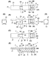
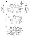
- FIG. 1 It is a perspective view which shows the frame member to which the latch component is fixed.
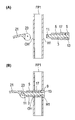
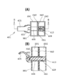
- A) is a front view of the latch component
- B) is a plan view
- C) is a bottom view
- D is a right side view
- E is a left side view
- F is (B).
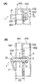
- A) and (B) are sectional views showing until the latch component is attached to the first member.
- FIG. (A) and (B) are diagrams for explaining a swell latch structure in which a first member to which a latch component is attached and a second member are latched so as not to be separated from each other in contact with each other.
- FIG. 1 A) and (B) are diagrams for explaining a swell latch structure in which a first member to which a latch component is attached and a second member are latched so as not to be separated from each other in contact with each other.
- FIG. 1 A) and (B) are diagrams for explaining a swell latch structure in which a first member to which a latch component is attached and a second member are latched so as not to be separated from each other in contact with each other. It is a figure for demonstrating the function of the three protrusions 19A to 19C provided in a tubular member.
- FIG. 1 It is a figure which shows the latch component of 2nd Embodiment and the swell latch structure using the latch component, (A) is the perspective view before latch, (B) is the front view after latch. Is a view showing the latch component of the third embodiment, (A) is a front view of the latch component, and (B) is a plan view. It is a figure which shows the shape of the facing through hole OH which fixes a latch component.
- (A) is a front view of the latch component of the fourth embodiment,
- (B) is a plan view,
- C) is a right side view,
- D) is a left side view, and (E) is shown in (B). It is a sectional view taken along the line EE.
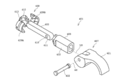
- FIG. 1 A) to (C) are cross-sectional views showing a procedure for latching a first member and a second member in a swell latch structure using the latch component. It is an exploded perspective view of the latch component of 5th Embodiment.
- (A) is a front view of the rod member,
- (B) is a plan view, and
- (C) is a left side view.
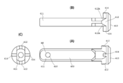
- (A) is a perspective view of the tubular member,
- (B) is a front view,
- (C) is a plan view, and (D) is a left side view.
- (A) is a side view of the lever member
- (B) is a right side view
- (C) is a bottom view
- (D) is a view showing a cam surface region on the DD line sectional view shown in (B).
- (E) is a diagram illustrating a region of an extended cam surface on the same DD line cross-sectional view.
- 17 (A) is a front view of a divided piece constituting the expansion / contraction member
- (B) is a view taken along the line B shown in (A)
- FIG. 17 (C) is a view taken along the line C shown in (B).
- (D) is a view taken along the arrow D shown in (B)
- (E) is a cross-sectional view taken along the line EE shown in (D).
- (A) and (B) are diagrams showing a procedure for latching a first member and a second member in a swell latch structure using the latch component of the fifth embodiment.
- (A) to (E) are diagrams showing a procedure for latching a first member and a second member in a swell latch structure using the latch component of the fifth embodiment.
- (A) to (E) are diagrams showing a procedure for latching a first member and a second member in a swell latch structure using the latch component of the fifth embodiment.
- FIG. 1 is a perspective view showing a frame member to which a latch component is fixed.
- the latch component 1 is fixed to a rectangular frame member FE (in FIG. 1, when distinguished, the frame members are designated by FE1 and FE2).
- the frame member FE is a hollow frame member made of metal such as aluminum, and through holes through which the latch component 1 penetrates are formed in two pillar portions FP1 and FP2 extending upward from the floor surface F, respectively.
- the latch component 1 is preliminarily fixed to the through hole of one pillar portion FP1 of the frame member FE, and the through hole is formed in the other pillar portion FP2. ..
- one pillar member FP1 of the frame member FE1 is the "first member”
- the other pillar member FP2 of the frame member FE2 is the “second member”.
- the latch member 1 latches the one pillar member FP1 of the frame member FE1 and the other pillar member FP2 of the frame member FE2 so as not to separate from each other.
- (A) is a front view of the latch component 1
- (B) is a plan view
- (C) is a bottom view
- (D) is a right side view
- (E) is a left side view
- (F) is (B). ) Is a sectional view taken along line FF.
- the latch member 1 of the present embodiment is composed of a rod member 3, a tubular member 5, a drive mechanism 7, and a scaling member 9.
- These constituent members (3 to 9) are mainly made of resin, but it is also possible to partially (for example, rod member 3) or all of them made of metal in order to increase the strength.
- the latch component 1 is a dedicated type having a fixed fastening distance.
- the rod member 3 is a rod-shaped member, and has a connecting portion 11 at one end and an acting portion 13 at the other end.
- the tubular member 5 slidably houses the rod member 3 in a state where the connecting portion 11 of the rod member 3 protrudes from one end and the working portion 13 is exposed from the other end.
- an inclined portion having an annular inclined surface 15 that inclines in a direction in which the distance between the tubular member 5 and the rod member 3 decreases toward the working portion 13 is provided.
- the tubular member 5 is integrally provided with a convex portion 17 extending in the radial direction from the outer peripheral surface of the tubular member 5 at a position separated from the inclined surface 15 toward one end side of the tubular member 5.
- Three protruding portions 19A to 19C which are provided at intervals in the circumferential direction and project in the radial direction, are integrally provided between the convex portion 17 and the inclined surface 15.
- the drive mechanism 7 is provided at one end of the rod member 3, and when the lever member 21 as an operating portion is operated, the rod member 3 is linearly moved in the longitudinal direction LD of the tubular member 5.
- the drive mechanism 7 can be a lever member 21 with a cam provided at one end of the rod member 3 and rotating about a shaft AX extending in a direction orthogonal to the longitudinal direction LD of the rod member 3.
- the cam 23 engages with one end of the tubular member 5, the acting portion 13 moves the rod member 3 toward the inclined surface 15, and the acting portion 13 is inclined. It has a cam surface 25 configured so that it can be selected to move away from the surface 15 according to the rotation direction of the lever member 21. Specifically, as shown in FIG.
- the cam 23 is an eccentric cam having a shape in which the distance D2 is longer than the distance D1 from the axis AX to the cam surface 25.
- the cam surface 25 includes an extension cam surface 27 extending radially outward of the tubular member 3 from the outer peripheral portion of one end in a state of being engaged with one end 5A of the tubular member 5.
- the expansion / contraction member 9 is arranged between the other end 5B of the tubular member 5 and the working portion 13, and the rod member 3 is driven by the drive mechanism 7 so that the working portion 13 approaches the other end 5B of the tubular member 5.
- the radial dimension becomes large, and the acting portion 13 moves in the direction away from the other end 5B of the tubular member 5.
- the pressed state between the acting portion 13 and the other end 5B of the tubular member 5 is released, and the radial dimension is reduced.
- the expansion / contraction member 9 is arranged so as to surround the outer peripheral portion of the rod member 3 protruding from the other end 5B of the tubular member 5, and the three divided pieces 29A to align in the circumferential direction of the rod member 3. It is composed of 29C and a connecting member 31 that connects the three divided pieces 29A to 29C so as to allow the three divided pieces 29A to 29C to move in the radial direction in an aligned state.
- the connecting member 31 is a garter spring in which both ends of the coil spring are connected to form an annular shape.
- the length of the inclined surface 15 and the structure of the expansion / contraction member 9 are such that when the working portion 13 moves to the maximum toward the inclined surface 15, a part of the expansion / contraction member 9 exceeds the inclined surface 15 and other than the tubular member 3. It is defined to be located on the edge side.
- the latch component 1 of the present embodiment is configured in this way, and the portion of the cam surface 25 in which the lever member 21 is rotated around the shaft AX and the distance from the shaft AX is the distance D2 is cylindrical.
- the rod member 3 is driven and the acting portion 13 moves in a direction approaching the other end 5B of the tubular member 5, and the expansion / contraction member 9 is pushed onto the inclined surface 15. Slide to increase the radial dimension.
- the latch member 1 sandwiches what is between the expansion / contraction member 9 and the cam surface 25 at this time, and the distance of the longitudinal LD between the expansion / contraction member 9 and the cam surface 25 of the lever member at this time is fastened.
- Distance FD is the portion of the cam surface 25 in which the lever member 21 is rotated around the shaft AX and the distance from the shaft AX is the distance D2 is cylindrical.
- FIG. 3A and 3B are cross-sectional views showing a process of attaching the latch component 1 to the first member (FP1).
- the latch component 1 of the present embodiment is used in a state of being attached to the first member (FP1).
- a circular first through hole H1 and a circular facing through hole OH are formed in one pillar portion FP1 of the frame member FE1, which is the first member.
- the diameter of the through hole H1 is larger than the diameter of the facing through hole OH, and the protrusion 17 of the tubular member 5 can pass through.
- the diameter of the facing through hole OH is such that the convex portion 17 of the tubular member 5 cannot pass through.
- the main body portion of the latch component 1 with the lever member 21 removed is inserted into the first member (FP1) from the through hole H1 (state of FIG. 3A). ), Further, the connecting portion 11 of the rod member 3 is projected from the facing through hole OH. In this state, the lever member 21 is attached to the connecting portion 11 (state of FIG. 3B).
- the latch component 1 can move in the longitudinal direction LD by the distance between the convex portion 17 and the cam 23 (particularly the extension cam surface 27) with respect to the first member (FP1). It will be fixed in a state where it cannot be removed from the member (FP1).
- the expansion / contraction member 9 and the acting portion 13 are housed in the first member (FP1). I'm designing. As a result, the latch component 1 does not get in the way when the frame member FE is arranged along the wall W as in the frame member FE2 shown in FIG.
- FIGS. 4 to 6 are views for explaining a swell latch structure in which a first member (FP1) to which a latch component 1 is attached and a second member (FP2) are latched so as not to be separated from each other in contact with each other.
- 4A to 6A are plan views
- FIG. 6B is a front sectional view.
- the contact surface CS1 of the first member (FP1) and the contact surface CS2 of the second member (FP2) are surfaces that come into contact with each other when latched, and the non-contact surface NS1 and the non-contact surface NS2 are on opposite sides thereof, respectively.
- the non-contact surface NS1 is the surface of the wall portion on which the facing through hole OH is formed).
- a circular second through hole H2 is formed in the other pillar member FP2 of the frame member FE2 which is the second member.
- the diameter dimension of the second through hole H2 is a dimension through which the expansion / contraction member 9 in a state where the radial dimension is small can pass, and has the same diameter dimension as the first through hole H1.
- the fastening distance FD of the latch component 1 of the present embodiment is designed to match the distance between the non-contact surface NS1 of the first member (FP1) and the non-contact surface NS2 of the second member (FP2). There is.
- the expansion / contraction member 9 of the latch component 1 is positioned at a position beyond the non-contact surface NS2 of the second member (FP2).
- the lever member 21 is rotated around the shaft AX so that the portion of the cam surface 25 whose distance from the shaft AX is the distance D2 comes into contact with the tubular member 5. Is driven and the acting portion 13 moves in a direction approaching the other end 5B of the tubular member 5, and the expansion / contraction member 9 is pushed and slides on the inclined surface 15 to increase the radial dimension.
- the expansion / contraction member 9 presses the non-contact surface NS2 of the second member (FP2), and the cam surface 25 of the lever member 21 presses the non-contact surface NS1 of the first member (FP1).
- the first member (FP1) and the second member (FP2) cannot be separated from each other (states of FIGS. 6A and 6B).
- protrusions 19A to 19C As described above, in the latch component 1 of the first embodiment shown in FIGS. 1 to 6, the tubular member 5 is provided with three protrusions 19A to 19C. In order to explain the functions of the three protrusions 19A to 19C, FIG. 7 is shown in inverse proportion.
- the latch component 1 of FIG. 7 does not have three protrusions 19A to 19C.
- the parts common to the first embodiment are designated by the same reference numerals and the description thereof is omitted. do.
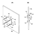
- FIGS. 8 (A) and 8 (B) are views showing a latch component of the second embodiment and a swell latch structure using the latch component
- FIG. 8 (A) is a perspective view before the latch
- (B) Is a front view after the latch.
- This example is the same as the first embodiment except that the latch component does not have a convex portion (reference numeral 17 of the first embodiment), and thus is a portion common to the first embodiment.
- the description of the above will be omitted by adding reference numerals to the reference numerals given in FIGS. 1 to 6 plus 100.
- the first member is the panel PL
- the second member is the plate-shaped wall surface member WL.
- a plurality of first through holes H1 are formed in the panel PL
- a plurality of corresponding second through holes H2 are formed in the wall surface member WL.
- the latch component 101 is not fixed to the first member (PL) or the second member (WL). Further, the fastening distance FD of the latch component 101 is designed to match the thickness dimension of the panel PL and the wall surface member WL.
- the side of the panel PL is in a state where the plurality of first through holes H1 of the panel PL and the plurality of second through holes H2 of the wall surface member WL are aligned (state of FIG. 8A).
- the cam surface 125 of the latch component 101 is inserted until it comes into contact with the panel PL, and in this state, the lever member 121 is rotated around the shaft AX, and the portion of the cam surface 125 whose distance from the shaft AX is D2 is formed.
- the rod member 103 When the rod member 103 is brought into contact with the tubular member 105, the rod member 103 is driven and the acting portion 113 moves in a direction approaching the other end 105B of the tubular member 105, and the expansion / contraction member 109 is pushed and slides on the inclined surface 115. Therefore, the radial dimension becomes large. As a result, the expansion / contraction member 109 presses the non-contact surface NS2 of the wall surface member WL (second member), and the cam surface 125 of the lever member 121 presses the non-contact surface NS1 of the panel PL (first member). By doing so, the panel PL does not separate from the wall surface member WL (state of FIG. 8B). In this way, the latch component 101 can be used for fastening the panel PL to the wall surface member WL.
- FIGS. 9A and 9 (B) are views showing the latch component of the third embodiment, (A) is a front view of the latch component, (B) is a plan view, and FIG. 10 shows the latch component. It is a figure which shows the shape of the facing through hole OH to fix.
- FIGS. 9A and 9B the parts common to the first embodiment are designated by the reference numerals obtained by adding 200 to the reference numerals given in FIGS. 1 to 6, and the description thereof will be omitted. do.
- the facing through holes OH have a barrel shape in which the facing sides arranged in parallel are connected by two arcs, and the outer peripheral portion of the tubular member 205 of the latch component 201 is formed.
- the shape is circular on the other end side, whereas the one end side has facing wall portions 233 and 233, and has a shape consistent with the facing through hole OH.
- the portion where the circular portion protrudes becomes the convex portion 217, which serves as the convex portion 17 of the first embodiment, and the latch member 201 becomes the convex portion 217 with respect to the first member.
- it can move in the longitudinal direction LD by the distance between the cams 223 (particularly the extension cam surface 227), it is fixed in a state where it cannot be removed from the first member (FP1).
- the number of the divided pieces 229A and 229B is two. In line with this, there are also two protrusions 219A and 219B located between the two divided pieces 229.
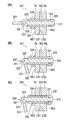
- FIGS. 11 and 12 are cross-sectional views showing a procedure for latching a first member and a second member in a swell latch structure using the latch component. be.
- FIGS. 11 and 12 the parts common to the first embodiment are designated by reference numerals obtained by adding 300 to the reference numerals given in FIGS. 1 to 6, and the description thereof will be omitted.
- the latch part 301 is a flexible type whose fastening distance can be changed. Further, the latch component 301 is for fastening the first member, which is the panel PL, to the second member, which is the wall surface member WL, as in the second embodiment, and is the first member (PL) and the first member. It is not fixed to the member (WL) of 2.
- the outer peripheral portion of the tubular member 305 of the latch component 301 is provided with a movable fixing component that can move in the longitudinal direction LD on the outer peripheral portion and does not move in the longitudinal direction LD at an arbitrary position on the outer peripheral portion.
- a movable fixing mechanism 335 is mounted.
- the movable fixing mechanism 335 is a movable fixing component having a male threaded portion 337 formed on the outer peripheral surface of the tubular member 305 along the longitudinal direction LD and a female threaded portion screwed into the male threaded portion 337. It is a nut member 339.
- the fastening distance can be changed by moving the nut member 339.
- cam 323 of the lever member 321 of the latch component 301 also has a cam surface 325'having the same shape as the cam surface 325, and the lever member 321 can rotate in two directions about the shaft AX.
- the nut member 339 is previously moved to a position closer to one end 305B of the tubular member 305 before latching the first member (PL) and the second member (WL). Then, as in the second embodiment, the plurality of first through holes H1 of the panel PL and the plurality of second through holes H2 of the wall surface member WL are inserted from the side of the panel PL in a aligned state (FIG. 12 (A)), in which the lever member 321 is rotated around the shaft AX (state of FIG. 12B). In this embodiment, in this state, the first member (PL) and the second member (WL) are not pressed by the latch component 301 and are not latched.
- the expansion / contraction member 309 presses the non-contact surface NS2 of the wall surface member WL (second member), and the nut member 339 presses the panel PL.
- the non-contact surface NS1 of (the first member) is pressed, and the latch component 301 latches the panel PL and the wall surface member WL (state of FIG. 12C).
- the latch component 301 should be left in that position without rotating the nut member 339 after rotating the lever member 321 to release the pressing and removing the latch component 301.
- the adjustment of the nut member 339 becomes unnecessary.
- FIG. 14A is a front view of the rod member
- FIG. 13B is a plan view
- FIG. 15C is a left side view
- FIG. 15A. Is a perspective view of the tubular member
- (B) is a front view
- (C) is a plan view
- (D) is a left side view
- FIG. 16 (A) is a side view of the lever member, and (B) is a right side view.
- FIG. 17A is a front view of the division piece constituting the expansion / contraction member
- FIG. 17A is a front view of the division piece constituting the expansion / contraction member
- (C) is a view which looked at the divided piece from the direction of the arrow of C shown in (B)
- (D) is the figure which looked at the divided piece from the direction of the arrow of D shown in (B).
- (E) is a sectional view taken along line EE shown in (D).
- two divided pieces 429 having the same shape and the same dimensions as those shown in FIGS. 17 (A) to 17 (E) are used (hereinafter, the two divided pieces 429 are distinguished from each other). In this case, it is distinguished as divided pieces 429A and 429B).
- 18 to 20 are views showing a procedure for latching a first member and a second member in a swell latch structure using the latch component of the fifth embodiment.
- the parts common to the first embodiment are designated by reference numerals obtained by adding 400 to the reference numerals given in FIGS. 1 to 6, and the description thereof will be omitted.
- the latch component 401 includes a rod member 403, a tubular member 405, a drive mechanism 407, and an expansion / contraction member 409.
- the connecting member 431 (garter spring) is not shown.
- the latch component 1 is a dedicated type having a fixed fastening distance.
- the rod member 403 is a rod-shaped member, and has a connecting portion 411 at one end and an acting portion 413 at the other end.
- the acting portion 413 has two protrusions 421 and 412 arranged so as to be located between the two split pieces 429A and 429B constituting the expansion / contraction member 409, and two split pieces 429A and 429B for positioning the two split pieces 429A and 429B.
- Positioning protrusions 414 and 414 are formed.
- the two protrusions 421 and 412 have a top that extends toward the other end of the connecting portion 411 or the tubular member 405 and whose circumferential dimension decreases toward the other end of the connecting portion 411 or the tubular member 405. ing.
- the two protrusions 421 and 412 also have a contour shape in which the circumferential dimension decreases toward the top from the working portion 413, and the two protrusions 421 and 412 face each other in the radial direction. It is formed.
- each of the two protrusions 421 and 412 has a pair of side surfaces 412A and 412A facing each other in the circumferential direction, and the pair of side surfaces 412A and 412A have the protrusion contact surfaces of the two divided pieces 429A and 429B, respectively. It is in contact with 429a (FIG. 17B).
- the two positioning protrusions 414 and 414 are adapted to engage with the positioning recesses 429b (FIG. 17A) of the two split pieces 429A and 429B, respectively.
- the rod member 403 is slidably housed in a state where the connecting portion 411 of the rod member 403 protrudes from one end and the working portion 413 is exposed from the other end. ..
- an inclined portion 415 having an inclined surface 415a inclined in a direction in which the distance between the rod member 403 and the rod member 403 becomes shorter toward the acting portion 413 of the stored rod member 403 is configured.
- the two distributed inclined portions 415A and 415B are provided at positions facing each other in the radial direction. The two distributed inclined portions 415A and 415B come into contact with the inclined surfaces 429c (FIG.
- the two distributed inclined portions 415A and 415B and the two protruding portions 421 and 412 are arranged in a positional relationship of 90 degrees apart in the circumferential direction. Further, the other end of the tubular member 405 is formed at a position facing the two protrusions 421 and 412 of the rod member 403 in the longitudinal direction, and is arranged so as to be located between the two divided pieces 429A and 429B. Two tubular member-side protrusions 416 and 416 are formed.
- the shape of the outer peripheral portion of the tubular member 405 is circular on the other end side in order to pass through the barrel-shaped facing through hole OH shown in FIG. While it is plate-shaped, the portion extending from the other end to one end side has facing planes 433 and 433 that face each other in parallel.
- the drive mechanism 407 is provided in the connecting portion 411 of the rod member 403, and when the lever member 421 as the operating portion is rotated in the forward direction, the rod member 403 is turned into a tubular member. It is linearly moved in the longitudinal LD of 405.
- the drive mechanism 407 has a shaft member 422 having an axis AX extending in a direction orthogonal to the longitudinal LD of the tubular member 405 or the rod member 403 through a through hole 410 provided in the connecting portion 411 of the rod member 403, and a shaft. It can be a lever member 421 with a cam that rotates around the member 422.
- the cam 423 of the lever member 421 with a cam engages with one end of the tubular member 405 so that the acting portion 413 moves the rod member 403 toward the inclined surface 415 and the acting portion 413 is tilted.
- a pair of cam surfaces 425 configured to be able to select to move away from the surface 415 according to the rotation direction of the lever member 421, and a pair of cam surfaces 425 engage with one end of the tubular member 403. Then, when the lever member 421 is further rotated in the forward direction, a pair of additional cam surfaces 427 for pressing the member located radially outside the tubular member 403 from the outer peripheral portion of one end of the tubular member 403 is provided. ing. Specifically, as shown in FIGS.
- the cam 423 exists at a position closer to the connecting portion 411 with the connecting portion 411 of the rod member 403 interposed therebetween, and is a distance from the axis AX.
- the contact state changes depending on the distance from the axis AX, which exists outside the P11 / P12 region (S11), the P12 / P13 region (S12), and the P13 / P14 region (S13). It has a region between P21 and P22 (S21), a region between P22 and P23 (S22), and a region between P23 and P24 (S23).
- the pair of cam surfaces 425 is the region between P12 and P13 (S12), and the pair of additional cam surfaces 427 is the region between P22 and P23 (S22) and the region between P23 and P24 (S23). That is.
- the area between P12 and P13 (S12) on the cam surface 425 and the area between P23 and P24 (S23) on the additional cam surface 427 are shaded.
- the contact state between the cam surface 425 and the additional cam surface 427 will be described later.
- the lever member 421 is rotatably fixed to one end of the rod member 403 by a shaft member 422 having an axis AX.
- the expansion / contraction member 409 is composed of the two divided pieces 429 shown in FIGS. 17A to 17E and the connecting member (garter spring) 431.
- the two divided pieces 429 are formed with a protrusion contact surface 429a, a positioning recess 429b, an inclined surface 429c, and a circumferential recess 429d into which the connecting member 431 is fitted, respectively.
- FIGS. 18 to 20 are diagrams illustrating a swell latch structure in which a first member (FP1) to which a latch component 401 is attached and a second member (FP2) are latched so as not to be separated from each other in contact with each other.
- FP1 first member
- FP2 second member
- FIG. 18 (A) plan view and (B) front view are views corresponding to the state shown in FIG. 5 of the first embodiment (latch component 401 until the lever member 421 contacts the periphery of the facing through hole OH). It is a figure of the state where is pushed in. In this state, the expansion / contraction member 409 of the latch component 401 is located at a position beyond the non-contact surface NS2 of the second member (FP2), and the region between P11 and P12 of the lever member 421 is a tubular member. It faces the end face of 405, and the region between P21 and P22 of the lever member 421 faces the first member (FP1).
- FIGS. 18 A) plan view, (B) front view, (C) CC line cross-sectional view, (D) DD line cross-sectional view, (E) partially enlarged view are FIGS. 18 (A) and ( From the state of B), the lever member 421 is rotated in the forward direction around the axis AX so that the region (S12) between P12 and P13, which is a pair of cam surfaces 425, faces the end surface of the tubular member 405. It is a figure which shows the state which was done. When the pair of cam surfaces 425 (region between P12 and P13) comes into contact with the end surface of the tubular member 405, the rod member 403 is driven and the acting portion 413 moves in a direction approaching the other end 405B of the tubular member 405.
- the expansion / contraction member 409 is pushed and expanded by the two protrusions 421 and 412 while sliding on the inclined surface 415 to increase the radial dimension (the expanded state of the expansion / contraction member 409 is the "first stage”. ").
- the region between P22 and P23, which is a pair of additional cam surfaces 427, is also in contact with the first member (FP1).
- the lever member 421 is rotated in the forward direction around the axis AX, and the region between P13 and P14 of the lever member 421 faces the end surface of the tubular member 405, and the region between P13 and P14 is the tubular member 405.
- the expansion / contraction member 409 is expanded (that is,) because the region between P22 and P23, which is a pair of additional cam surfaces 427, is in contact with the first member (FP1). The first stage) is maintained.
- the expansion / contraction member 9 presses the non-contact surface NS2 of the second member (FP2) by the acting portion 413 of the rod member 403, and the pair of extension cam surfaces 427 of the lever member 421 is the first member ( By pressing the non-contact surface NS1 of the FP1), the first member (FP1) and the second member (FP2) cannot be separated (this state is referred to as "second stage").
- the lever member 421 is rotated in the opposite direction around the axis AX so that the portion of the cam surface 425 whose distance from the axis AX is the distance D1 faces the tubular member 405, and the pressing is released. , The first member (FP1) and the second member (FP2) are separated from each other.
- the present invention is not limited to the present embodiment as long as it does not deviate from the gist thereof.
- the present invention is not limited to the present embodiment as long as it does not deviate from the gist thereof.
- sandwiching a washer between the lever member and the first member of the latch component the case where the lever member and the first member come into contact with each other via the washer member is naturally included.
- the present invention it is possible to provide a latch component and a swell latch structure in which the drive mechanism operates even in the state of a single item, which is not fixed to the first member. Further, according to the present invention, it is possible to provide a latch component and a swell latch structure that can be prevented from protruding from the first member.
Landscapes
- Engineering & Computer Science (AREA)
- General Engineering & Computer Science (AREA)
- Mechanical Engineering (AREA)
- Mutual Connection Of Rods And Tubes (AREA)
- Lock And Its Accessories (AREA)
- Clamps And Clips (AREA)
Priority Applications (1)
| Application Number | Priority Date | Filing Date | Title |
|---|---|---|---|
| JP2022535335A JP7691754B2 (ja) | 2020-07-07 | 2021-07-06 | ラッチ部品及びスウェルラッチ構造 |
Applications Claiming Priority (2)
| Application Number | Priority Date | Filing Date | Title |
|---|---|---|---|
| JP2020117057 | 2020-07-07 | ||
| JP2020-117057 | 2020-07-07 |
Publications (1)
| Publication Number | Publication Date |
|---|---|
| WO2022009868A1 true WO2022009868A1 (ja) | 2022-01-13 |
Family
ID=79553151
Family Applications (1)
| Application Number | Title | Priority Date | Filing Date |
|---|---|---|---|
| PCT/JP2021/025421 Ceased WO2022009868A1 (ja) | 2020-07-07 | 2021-07-06 | ラッチ部品及びスウェルラッチ構造 |
Country Status (2)
| Country | Link |
|---|---|
| JP (1) | JP7691754B2 (https=) |
| WO (1) | WO2022009868A1 (https=) |
Citations (3)
| Publication number | Priority date | Publication date | Assignee | Title |
|---|---|---|---|---|
| JPS6244046Y2 (https=) * | 1982-07-24 | 1987-11-18 | ||
| EP0480534A1 (en) * | 1990-10-11 | 1992-04-15 | Naamloze Vennootschap Koninklijke Sphinx | Device for fastening a seat on a lavatory bowl |
| US5931516A (en) * | 1998-01-06 | 1999-08-03 | Southco, Inc. | Swell latch assembly |
-
2021
- 2021-07-06 JP JP2022535335A patent/JP7691754B2/ja active Active
- 2021-07-06 WO PCT/JP2021/025421 patent/WO2022009868A1/ja not_active Ceased
Patent Citations (3)
| Publication number | Priority date | Publication date | Assignee | Title |
|---|---|---|---|---|
| JPS6244046Y2 (https=) * | 1982-07-24 | 1987-11-18 | ||
| EP0480534A1 (en) * | 1990-10-11 | 1992-04-15 | Naamloze Vennootschap Koninklijke Sphinx | Device for fastening a seat on a lavatory bowl |
| US5931516A (en) * | 1998-01-06 | 1999-08-03 | Southco, Inc. | Swell latch assembly |
Also Published As
| Publication number | Publication date |
|---|---|
| JP7691754B2 (ja) | 2025-06-12 |
| JPWO2022009868A1 (https=) | 2022-01-13 |
Similar Documents
| Publication | Publication Date | Title |
|---|---|---|
| US7547156B2 (en) | Lock pin with pushbutton-operated axial locking and free bearing | |
| JP5701222B2 (ja) | リニアストッパ | |
| CN114341517B (zh) | 反向输入切断离合器 | |
| JP6872237B2 (ja) | 操作棒の連結構造 | |
| US11565384B2 (en) | Toggler structure for ratchet wrench | |
| US9446626B2 (en) | Vehicle wheel hub assembly | |
| US7119297B2 (en) | Push button | |
| JP5340892B2 (ja) | 操作スイッチ | |
| US6675674B2 (en) | Locating/controlling structure for telescopic tube | |
| CN107105591B (zh) | 活动把手 | |
| WO2022009868A1 (ja) | ラッチ部品及びスウェルラッチ構造 | |
| US8523199B2 (en) | Stroller and headrest-adjusting mechanism thereof | |
| US11306763B2 (en) | Nut | |
| EP2302227A1 (en) | Screw grommet | |
| JP5717221B1 (ja) | 連結具 | |
| JPWO2022009868A5 (https=) | ||
| JP2020515370A (ja) | ダンス練習ポール用の端部アセンブリ | |
| US10871183B2 (en) | Method for manufacturing floating joint, and floating joint manufactured by said method | |
| US6787721B1 (en) | Safety switch of screwdriver | |
| TWM608247U (zh) | 把手結構 | |
| JP2020094474A (ja) | ラッチ機構 | |
| CN219170761U (zh) | 拆卸工具 | |
| JP2019060360A (ja) | 早送りナット | |
| TWI647074B (zh) | 滑桿工具 | |
| JP7333046B2 (ja) | ラッチ錠のハンドルの台座ユニット |
Legal Events
| Date | Code | Title | Description |
|---|---|---|---|
| 121 | Ep: the epo has been informed by wipo that ep was designated in this application |
Ref document number: 21838868 Country of ref document: EP Kind code of ref document: A1 |
|
| ENP | Entry into the national phase |
Ref document number: 2022535335 Country of ref document: JP Kind code of ref document: A |
|
| NENP | Non-entry into the national phase |
Ref country code: DE |
|
| 122 | Ep: pct application non-entry in european phase |
Ref document number: 21838868 Country of ref document: EP Kind code of ref document: A1 |