WO2022009602A1 - 情報処理装置、情報処理方法、及びプログラム - Google Patents
情報処理装置、情報処理方法、及びプログラム Download PDFInfo
- Publication number
- WO2022009602A1 WO2022009602A1 PCT/JP2021/022191 JP2021022191W WO2022009602A1 WO 2022009602 A1 WO2022009602 A1 WO 2022009602A1 JP 2021022191 W JP2021022191 W JP 2021022191W WO 2022009602 A1 WO2022009602 A1 WO 2022009602A1
- Authority
- WO
- WIPO (PCT)
- Prior art keywords
- cluster
- point cloud
- information processing
- group
- unit
- Prior art date
- Legal status (The legal status is an assumption and is not a legal conclusion. Google has not performed a legal analysis and makes no representation as to the accuracy of the status listed.)
- Ceased
Links
Images


Classifications
-
- G—PHYSICS
- G05—CONTROLLING; REGULATING
- G05D—SYSTEMS FOR CONTROLLING OR REGULATING NON-ELECTRIC VARIABLES
- G05D1/00—Control of position, course, altitude or attitude of land, water, air or space vehicles, e.g. using automatic pilots
- G05D1/02—Control of position or course in two dimensions
- G05D1/021—Control of position or course in two dimensions specially adapted to land vehicles
- G05D1/0268—Control of position or course in two dimensions specially adapted to land vehicles using internal positioning means
- G05D1/0274—Control of position or course in two dimensions specially adapted to land vehicles using internal positioning means using mapping information stored in a memory device
-
- G—PHYSICS
- G05—CONTROLLING; REGULATING
- G05D—SYSTEMS FOR CONTROLLING OR REGULATING NON-ELECTRIC VARIABLES
- G05D1/00—Control of position, course, altitude or attitude of land, water, air or space vehicles, e.g. using automatic pilots
- G05D1/20—Control system inputs
- G05D1/24—Arrangements for determining position or orientation
- G05D1/246—Arrangements for determining position or orientation using environment maps, e.g. simultaneous localisation and mapping [SLAM]
-
- G—PHYSICS
- G06—COMPUTING OR CALCULATING; COUNTING
- G06T—IMAGE DATA PROCESSING OR GENERATION, IN GENERAL
- G06T19/00—Manipulating 3D models or images for computer graphics
-
- G—PHYSICS
- G06—COMPUTING OR CALCULATING; COUNTING
- G06T—IMAGE DATA PROCESSING OR GENERATION, IN GENERAL
- G06T7/00—Image analysis
-
- G—PHYSICS
- G06—COMPUTING OR CALCULATING; COUNTING
- G06T—IMAGE DATA PROCESSING OR GENERATION, IN GENERAL
- G06T7/00—Image analysis
- G06T7/20—Analysis of motion
- G06T7/277—Analysis of motion involving stochastic approaches, e.g. using Kalman filters
Definitions
- This disclosure relates to information processing devices, information processing methods, and programs.
- Non-Patent Document 1 a technique for expressing the surrounding environment as an aggregate of minute planes based on the sensing result by a sensor or the like has been proposed (for example, Non-Patent Document 1).
- a technique has been proposed in which the surface of an object existing in the surrounding environment is expressed as point group data by acquiring the distance and direction to an object existing in the surrounding environment with a distance measuring sensor or the like.
- each of the first clusters included in the first cluster group in which the first point cloud data acquired by the sensor is clustered is the first point cloud data.
- each of the first clusters included in the first cluster group in which the first point cloud data acquired by the sensor is clustered by using an arithmetic processing device is used.
- the second cluster is fused with each of the second clusters included in the second cluster group generated based on the second point cloud data acquired in the past than the first point cloud data. Includes updating the group.
- each of the first clusters included in the first cluster group in which the computer is clustered with the first point cloud data acquired by the sensor is subjected to the first point cloud.
- each cluster of the first cluster group based on the first point group data acquired by the sensor is referred to as the first point group data.
- the second cluster group can be updated by fusing with each cluster of the second cluster group based on the second point group data acquired in the past.
- the surrounding environment can be expressed by using the cluster group in which the point cloud data acquired by the sensor is compressed by clustering, and the cluster group is sequentially fused in chronological order to form the cluster group. Can be updated.
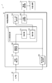
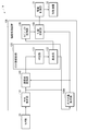
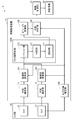
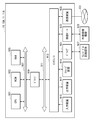
- FIG. 1 is a block diagram showing an example of the functional configuration of the mobile body 1 including the information processing apparatus 10 according to the present embodiment.
- the moving body 1 includes a sensor unit 20, an information processing device 10 according to the present embodiment, a drive control unit 31, and a moving mechanism 32. Further, the information processing apparatus 10 according to the present embodiment includes a plane estimation unit 110, a cluster group update unit 120, an object recognition unit 130, a self-position estimation unit 140, an action planning unit 150, and a coordinate system conversion unit 160. And.
- the moving body 1 is, for example, a robot or a drone that is provided with a moving mechanism 32 and can move autonomously.
- the information processing device 10 provided in the mobile body 1 constructs an environmental map based on the data acquired by the sensor unit 20, for example, and plans the movement route of the mobile body 1 based on the constructed environmental map. be able to.
- the movement path planned by the information processing apparatus 10 is output to, for example, a drive control unit 31 that controls the movement mechanism 32 of the moving body 1, so that the moving body 1 is moved along the planned moving path. Can be done.
- the information processing device 10 may be provided inside the mobile body 1, but it goes without saying that the information processing device 10 may be provided outside the mobile body 1.
- the information processing device 10 can output a route plan to the drive control unit 31 of the mobile body 1 via the internal wiring. Further, when the information processing device 10 is provided outside the mobile body 1, the information processing device 10 can transmit a route plan to the drive control unit 31 of the mobile body 1 via wireless communication or the like.
- the sensor unit 20 includes a sensor that senses the environment around the moving body 1, and outputs the sensing result as point cloud data that is a set of points.
- the sensor unit 20 is an ultrasonic sensor (Sound Navigation And Ringing: SONAR), a ToF (Time of Flyght) sensor, a RADAR (Radio Detection And Ringing), a LiDA (Light Detection And Range) sensor, or a LiDA (Light Detection) distance sensor. May include a range sensor to measure.
- the sensor unit 20 generates point cloud data by converting the measurement points into points in the three-dimensional coordinate system based on the information on the distance and orientation to the measurement points acquired from the distance measurement sensor. be able to.
- the sensor unit 20 may include an image pickup device that acquires an image of the surrounding environment of the moving body 1 such as a stereo camera, a monocular camera, a color camera, an infrared camera, a spectroscopic camera, or a polarized camera.
- the sensor unit 20 estimates the depth of the image points included in the captured image based on the captured image, and converts the image points into points in the three-dimensional coordinate system based on the information on the estimated depth. Then, the point cloud data can be generated.
- the sensor unit 20 may be provided in another device or object outside the moving body 1 as long as it can sense the environment around the moving body 1.
- the sensor unit 20 may be provided on the ceiling, wall, floor, or the like of the space in which the moving body 1 is present.
- the plane estimation unit 110 generates a cluster group by clustering the point cloud included in the point cloud data acquired by the sensor unit 20.
- the generated cluster group corresponds to the microplane group constituting the object surface existing around the moving body 1.
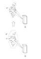
- FIG. 2 is an explanatory diagram illustrating point cloud data and clustering of point cloud data.
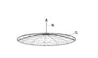
- FIG. 3 is an explanatory diagram schematically showing the shape of a cluster corresponding to a microplane constituting an object surface.
- the plane estimation unit 110 can generate a cluster group including a plurality of cluster CLs by clustering a point cloud PC which is a set of points P in a three-dimensional coordinate system.
- Each of the cluster CLs can be represented by a flat ellipsoid based on the center coordinates and the probability distribution shape of the cluster CLs, for example, as shown in FIG.
- the cluster CL may be represented by a flat ellipsoid whose center is the average value of the coordinates of the points included in the cluster CL and whose thickness is the covariance of the coordinates of the points included in the cluster CL.
- a vector NL indicating the thickness in the normal direction with respect to the flat plane and the thickness in the normal direction of the flat ellipsoid can be used as a representative parameter of the shape. That is, the plane estimation unit 110 can represent a microplane group constituting an object surface existing around the moving body 1 in a cluster group including a cluster represented by a flat ellipsoid.
- the plane estimation unit 110 divides the point cloud included in the point cloud data into a plurality of subpoint groups according to the following procedure, and clusters each of the divided subpoint groups to create an object.
- a cluster group corresponding to a microplane group constituting a surface may be generated.
- the plane estimation unit 110 first determines whether or not to divide the point cloud included in the point cloud data based on a predetermined division condition. When the point cloud satisfies a predetermined division condition, the plane estimation unit 110 divides the point cloud into substantially half and generates two partial point clouds. Next, the plane estimation unit 110 repeatedly divides the generated partial point cloud into substantially half until the above division condition is not satisfied. Subsequently, the plane estimation unit 110 determines whether or not to perform clustering for each of the partial point clouds divided until the above-mentioned division condition is not satisfied, based on a predetermined clustering condition. After that, the plane estimation unit 110 can generate a cluster group corresponding to the minute plane group constituting the object surface by performing clustering for each of the partial point groups satisfying a predetermined clustering condition.
- the above-mentioned predetermined division condition may include a condition that the number of points included in the point cloud is a predetermined number or more.
- the predetermined division condition is the length of the longest side of the rectangular parallelepiped region when the minimum rectangular parallelepiped region (also called a bounding box) containing all the points of the point group is set in the three-dimensional coordinate system. May include the condition that is greater than or equal to a predetermined length.
- the predetermined division condition may include a condition that the density of points in the point cloud is equal to or higher than a predetermined value.
- the density of points in the point cloud may be, for example, a value obtained by dividing the number of points included in the point cloud by the size of the above bounding box.
- the predetermined division condition may include a condition relating to the shape of the point cloud. Further, the predetermined division condition may include a condition in which a plurality of the above-mentioned conditions are combined.
- the predetermined clustering condition may include a condition that the number of points included in the point cloud is a predetermined number or more. Further, the predetermined clustering condition may include a condition that the length of the longest side of the bounding box is equal to or greater than the predetermined length. Further, the predetermined clustering condition may include a condition that the density of points in the above point cloud is equal to or higher than a predetermined value. Further, the predetermined clustering condition may include a condition relating to the shape of the point cloud. Further, the predetermined clustering condition may include a condition in which a plurality of the above-mentioned conditions are combined.
- the optimum conditions can be appropriately set based on the characteristics of the point cloud and the like.
- the plane estimation unit 110 performs clustering for each of the point clouds after the division until the predetermined division condition is not satisfied, the size of each of the point clouds to be clustered is reduced. be able to. Therefore, the plane estimation unit 110 can further shorten the clustering processing time. Further, since the plane estimation unit 110 can exclude a point cloud that does not satisfy a predetermined clustering condition and is likely to be inaccurate from the target of clustering, the accuracy of clustering can be further improved.
- the coordinate system conversion unit 160 converts the position coordinates of each cluster of the cluster group generated by the plane estimation unit 110 into relative coordinates with respect to the environment map. Specifically, the coordinate system conversion unit 160 converts the position coordinates of each cluster into relative coordinates to the environment map based on the self-position of the moving body 1 estimated by the self-position estimation unit 140 described later. For example, the position of the sensor unit 20 mounted on the moving body 1 changes as the moving body 1 moves. Therefore, the coordinate system conversion unit 160 sets the position coordinates of each cluster based on the point cloud data acquired by the sensor unit 20 based on the self-position of the moving body 1 on which the sensor unit 20 is mounted, as relative coordinates to the environment map. Convert to. As a result, the information processing apparatus 10 can handle the cluster group based on the point cloud data acquired by the sensor unit 20 on the same coordinates even when the position of the sensor unit 20 fluctuates.
- the cluster group update unit 120 updates the position and shape of each cluster of the cluster group corresponding to the microplane group constituting the object surface by using the point cloud data acquired by the sensor unit 20 at any time. Specifically, the cluster group updating unit 120 uses a cluster group (referred to as a first cluster group) in which the point group data (referred to as the first point group data) acquired by the sensor unit 20 is clustered. The second cluster is fused with the cluster group (second cluster group) generated based on the point group data (referred to as the second point group data) acquired in the past than the point group data of 1. The swarm may be updated.
- a cluster group referred to as a first cluster group
- the second cluster is fused with the cluster group (second cluster group) generated based on the point group data (referred to as the second point group data) acquired in the past than the point group data of 1.
- the swarm may be updated.
- the cluster group update unit 120 information-compresses the point cloud data acquired by the sensor unit 20 by clustering, and the information-compressed cluster group (first cluster group) is generated in the past (cluster group).
- the position and shape of each cluster in the second cluster group can be updated by sequentially fusing them into the second cluster group) in chronological order.
- the cluster group update unit 120 can use the cluster included in the cluster group as the data handling unit instead of the points included in the point cloud data, the amount of data to be handled and the amount of data calculation can be determined. Can be reduced. Therefore, the information processing apparatus 10 can more efficiently reflect the point cloud data acquired by the sensor unit 20 on the environment map.
- the cluster group update unit 120 includes the determination unit 121 and the fusion unit 122.
- the functions of the determination unit 121 and the fusion unit 122 will be described with reference to FIGS. 4 to 7.
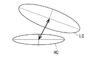
- FIG. 4 is an explanatory diagram illustrating an example of a method for determining a cluster to be fused.
- FIG. 5 is an explanatory diagram illustrating another example of a method for determining a cluster to be fused.
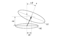
- FIG. 6 is an explanatory diagram illustrating a method of estimating the normal direction and the thickness of the first cluster and the second cluster to be fused.
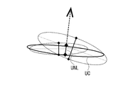
- FIG. 7 is an explanatory diagram showing the normal direction, the thickness, and the shape of the fusion cluster in which the first cluster and the second cluster are fused.
- each of the clusters represented by the flat ellipsoid as shown in FIG. 3 is represented by an elliptical shape which is a vertical cross section of the flat ellipsoid (that is, a cross-sectional view in the normal direction of the cluster).
- the determination unit 121 determines the combination of the cluster included in the first cluster group (referred to as the first cluster) and the cluster included in the second cluster group (referred to as the second cluster) to be fused.
- the determination unit 121 is based on the position and shape of the first cluster LC included in the first cluster group and the position and shape of the second cluster HC included in the second cluster group. , The combination of the first cluster LC to be fused and the second cluster HC may be determined. Specifically, the determination unit 121 has an angle n ⁇ formed by the normal directions with respect to the flat planes of the first cluster LC and the second cluster HC, and the normal directions of the first cluster LC and the second cluster HC. Normalized distance nd (distance normalized by cluster thickness) and normalized distance cd (cluster short diameter length) in the planodirectional direction of each of the first cluster LC and the second cluster HC. The combination of the first cluster LC and the second cluster HC to be fused may be determined based on the distance).
- the determination unit 121 fuses the first cluster LC and the second cluster HC in which the angle n ⁇ formed by the normal direction, the distance nd in the normal direction, and the distance cd in the flat plane direction are equal to or less than the respective threshold values. It may be determined that it is a combination of clusters. Alternatively, the determination unit 121 fuses the first cluster LC and the second cluster HC in which the angle n ⁇ formed by the normal direction, the distance nd in the normal direction, and the distance cd in the flat plane direction satisfy a predetermined relational expression. It may be determined as a combination of clusters of.
- the determination unit 121 is based on the normalized distance between the first cluster LC included in the first cluster group and the second cluster HC included in the second cluster group. , The combination of the first cluster LC to be fused and the second cluster HC may be determined. Specifically, the determination unit 121 may determine the combination of the first cluster LC and the second cluster HC to be fused based on the distance normalized by the covariance.
- the covariance-normalized distance (Mahalanobis distance (mahalanobis_distance)) is such that the center point of the first cluster LC is ⁇ j , the covariance of the first cluster LC is ⁇ j, and the center point of the second cluster HC is Assuming that the covariance of ⁇ i and the second cluster HC is ⁇ i , it can be shown by the following formula group 1.
- the determination unit 121 may determine one second cluster HC for a plurality of first cluster LCs as a cluster to be fused, as long as the determination condition of the cluster to be fused is satisfied.
- One first cluster LC may be determined as a cluster to be fused with respect to the second cluster HC.
- the second cluster HC does not have to have the first cluster LC determined to be the fusion target. As will be described later, the second cluster HC, which has not been determined to be the fusion target for the first cluster LC for a predetermined period or longer, is discarded when the second cluster group is updated by fusion with the first cluster group. May be good.
- the first cluster LC does not have to have the second cluster HC determined to be the fusion target. In such a case, the first cluster LC will be added to the second cluster group without being fused with the second cluster HC.
- the fusion unit 122 fuses the first cluster LC and the second cluster HC determined to be fusion targets based on the shapes of the first cluster LC and the second cluster HC.
- the fusion portion 122 has the thickness in the normal direction and the normal direction (also referred to as the normal direction and the thickness LNL of the first cluster LC) with respect to the flat surface of the first cluster LC, and the first.
- the normal direction and the thickness in the normal direction of the two cluster HC with respect to the flat plane also referred to as the normal direction and the thickness HNL of the second cluster HC
- the fusion unit 122 uses the normal direction and thickness LNL of the first cluster LC estimated with high accuracy and the normal direction and thickness HNL of the second cluster HC, and the first cluster LC and the second cluster. Fuse HC.
- the fusion unit 122 can estimate the normal direction and thickness LNL of the first cluster LC and the normal direction and thickness HNL of the second cluster HC with high accuracy by using a Kalman filter. ..
- the fusion unit 122 defines the specifications of the Kalman filter using the cluster components shown below, and the first cluster is based on the Kalman filter prediction equation shown in the equation group 2 and the Kalman filter update equation shown in the equation group 3.
- the normal direction and thickness LNL of LC and the normal direction and thickness HNL of the second cluster HC may be estimated.
- x t Normal vector of the second cluster HC ( ⁇ x ) 2 t : Thickness in the normal direction of the second cluster HC
- z t Normal vector of the first cluster LC
- ⁇ z 2 Normal of the first cluster LC Thickness in the direction ⁇ w 2 : System noise (hyper parameter)
- the fusion unit 122 is a cluster after fusion based on the estimated normal direction and thickness LNL of the first cluster LC and the normal direction and thickness HNL of the second cluster HC.
- the normal direction and thickness UNL of UC are derived.
- the fusion unit 122 is a cluster UC after fusion in which the first cluster LC included in the first cluster group and the second cluster HC included in the second cluster group are fused.
- the position and shape of the second cluster HC included in the two cluster groups can be updated.
- the fusion unit 122 may fuse the first cluster LC and the second cluster HC by a simple fusion process based on the cluster shape. For example, suppose that the center point of the first cluster LC is ⁇ j , the covariance of the first cluster LC is ⁇ j , the center point of the second cluster HC is ⁇ i , and the covariance of the second cluster HC is ⁇ i.
- the center point ⁇ merged and the covariance ⁇ merged of the subsequent cluster UC can be expressed by the following formula group 4.
- the fusion unit 122 may fuse the first cluster LC and the second cluster HC in a fusion process including a fusion cluster pair based on the cluster shape. For example, suppose that the center point of the first cluster LC is ⁇ j , the covariance of the first cluster LC is ⁇ j , the center point of the second cluster HC is ⁇ i , and the covariance of the second cluster HC is ⁇ i.
- the center point ⁇ merged and the covariance ⁇ merged of the subsequent cluster UC can be expressed by the following formula group 5.
- the fusion unit 122 may fuse the first cluster LC and the second cluster HC by the fusion process using the cluster weight. Specifically, the fusion unit 122 combines the first cluster LC and the second cluster HC with the number of point clouds in the point cloud data used to generate the first cluster group and the second cluster group as the cluster weight. May be fused. For example, suppose that the center point of the first cluster LC is ⁇ j , the covariance of the first cluster LC is ⁇ j , the center point of the second cluster HC is ⁇ i , and the covariance of the second cluster HC is ⁇ i. The center point ⁇ merged and the covariance ⁇ merged of the subsequent cluster UC can be expressed by the following formula group 6.
- w i is the first point number group in group data points used to generate the group clusters including a first cluster LC
- w j is the generation of the second group of clusters including a second cluster HC It is the number of point clouds in the point cloud data used in.
- the fusion unit 122 may fuse the first cluster LC and the second cluster HC by the fusion process using the cluster reliability. Specifically, the fusion unit 122 uses the reliability of the sensor unit 20 when acquiring the point cloud data used for generating the first cluster group and the second cluster group as the cluster weight as the first cluster.
- LC and the second cluster HC may be fused. For example, suppose that the center point of the first cluster LC is ⁇ j , the covariance of the first cluster LC is ⁇ j , the center point of the second cluster HC is ⁇ i , and the covariance of the second cluster HC is ⁇ i.
- the center point ⁇ merged and the covariance ⁇ merged of the subsequent cluster UC can be expressed by the following formula group 7.
- c i is a first group of clusters reliability when acquiring the data point group used for the generation of including the first cluster LC, c j, the second cluster including a second cluster HC It is the reliability when the point cloud data used for the generation of the group is acquired.
- the second cluster HC that was not the target of fusion with the first cluster LC is the second cluster until a predetermined period. You may keep it in the group. After that, the fusion unit 122 may discard the second cluster HC, which has not been the target of fusion of the first cluster LC for a predetermined period or longer, at the time of updating the second cluster group. Further, among the first cluster LCs included in the first cluster group, the fusion unit 122 adds the first cluster LC, which was not the target of fusion with the second cluster HC, to the second cluster group as it is. May be good.
- the object recognition unit 130 recognizes an object corresponding to the grouped one or a plurality of clusters by grouping one or a plurality of clusters included in the cluster group updated by the cluster group update unit 120.
- the object recognition unit 130 may recognize the objects existing around the moving body 1 based on the shape, arrangement, mutual spacing, and the like of each cluster included in the cluster group.
- the object recognition unit 130 exists around the moving body 1 by associating the shape and arrangement of each cluster included in the cluster group with the image captured by the image pickup device included in the sensor unit 20. You may recognize the object to be used.
- the object recognition unit 130 constructs an environment map expressing each of the clusters using the center coordinates and the probability distribution shape based on the recognized object.
- the object recognition unit 130 may construct an environment map of a two-dimensional plane or may construct an environment map of a three-dimensional space.
- the object recognition unit 130 reduces the amount of data in the environment map by constructing the environment map using clusters represented by flat ellipsoids, as compared with the case where the environment map is constructed using the so-called grid map. can do. According to this, the object recognition unit 130 can construct the environment map in a short time even with less computational resources.
- the self-position estimation unit 140 estimates the position of the mobile body 1 on the environment map based on the information about the environment around the mobile body 1 acquired by the sensor unit 20. Further, the self-position estimation unit 140 generates self-position data indicating the estimated position of the moving body 1 and outputs the self-position data to the coordinate system conversion unit 160 and the action planning unit 150.
- the self-position estimation unit 140 may estimate the position of the moving body 1 based on the sensing result of the sensor that measures the state of the moving body 1. For example, the self-position estimation unit 140 calculates the movement direction and the movement distance of the moving body 1 based on the sensing result of the encoder provided at each joint of the leg portion included in the moving mechanism 32 of the moving body 1. The position of the moving body 1 may be estimated. For example, the self-position estimation unit 140 calculates the moving direction and the moving distance of the moving body 1 based on the sensing result of the encoder provided on each wheel included in the moving mechanism 32 of the moving body 1. The position of may be estimated.
- the self-position estimation unit 140 has a moving direction and a moving distance of the moving body 1 based on the sensing result of an IMU (Inertial Measurement Unit) having a 3-axis gyro sensor and a 3-way accelerometer provided in the moving body 1. You may estimate the position of the moving body 1 by calculating.
- IMU Inertial Measurement Unit
- the self-position estimation unit 140 may estimate the position of the moving body 1 based on the information acquired by another sensor such as a GNSS (Global Navigation Satellite System) sensor.
- GNSS Global Navigation Satellite System
- the action planning unit 150 creates an action plan for the moving body 1 by grasping the situation around the moving body 1 based on the information acquired from the sensor unit 20 and the like. Specifically, the action planning unit 150 may plan a movement route to the destination of the moving body 1 based on the environment map around the moving body 1 and the self-position data of the moving body 1.
- the drive control unit 31 controls the drive of the movement mechanism 32 to move the moving body 1 along the movement path planned by the action planning unit 150.
- the drive control unit 31 has a movement mechanism 32 so that the difference between the position of the moving body 1 on the moving path planned by the action planning unit 150 at a predetermined time and the actual position of the moving body 1 becomes small.
- the moving body 1 may be moved along the moving path.
- the moving mechanism 32 is, for example, a mechanism that enables the moving body 1 to move on the ground, on the water, in the water, or in the air.
- the moving mechanism 32 is a moving mechanism that enables traveling on the ground such as two-wheeled or four-wheeled wheels, a moving mechanism that allows walking on the ground such as two-legged or four-legged legs, and an aerial vehicle such as a propeller or a rotary wing. It may be a moving mechanism that makes it possible to fly, or a moving mechanism that makes it possible to move on or under water such as a screw.
- the information processing apparatus 10 can compress the point cloud data that senses the surrounding environment by clustering, and express the surrounding environment by the information-compressed cluster group. can. According to this, the information processing apparatus 10 can reduce the amount of data to be handled and the calculation load.
- the information processing apparatus 10 by estimating the normal direction and thickness of the cluster by the Kalman filter, the clusters can be sequentially fused using the normal direction and thickness estimated with higher accuracy. can. According to this, the information processing apparatus 10 can create an environment map in which the environment around the mobile body 1 is expressed with higher accuracy.
- the information processing apparatus 10 can shorten the processing time of the recognition processing of the surrounding environment, so that the response speed of the mobile body 1 can be improved. Further, since the information processing apparatus 10 can improve the recognition accuracy for the surrounding environment, it is possible to plan an efficient movement route with a smaller margin for the objects existing in the surrounding environment.
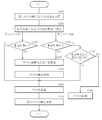
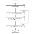
- FIG. 8 is a flowchart showing an example of the operation of the cluster group update unit 120.
- the determination unit 121 acquires the data of the first cluster group in which the point cloud data acquired by the sensor unit 20 is clustered (S101). Next, the determination unit 121 searches for and determines each of the first clusters included in the first cluster group to be fused and the second cluster included in the second cluster group (S102).
- the second cluster group is a cluster group generated in the past than the first cluster group. That is, the second cluster group is a cluster group generated by clustering the second point group data acquired in the past than the first point group data used for generating the first cluster group. Alternatively, it is a cluster group obtained by further updating the cluster group.
- the determination unit 121 determines whether or not there is a second cluster to be fused for each of the first clusters included in the first cluster group (S103).
- the first cluster (S103 / Yes) in which the second cluster to be fused exists is the first cluster to be fused in the cluster fusion process (S108) after the normal direction and thickness estimation (S107) described later. Fused with 2 clusters.
- the first cluster (S103 / No) in which the second cluster to be fused does not exist is directly added to the second cluster group in the step of cluster addition (S109).
- the determination unit 121 determines whether or not there is a first cluster to be fused for each of the second clusters included in the second cluster group (S104).
- the second cluster (S104 / Yes) in which the first cluster to be fused exists is the first cluster to be fused in the subsequent cluster fusion process (S108) after estimating the normal direction and thickness (S107). It is fused with one cluster.
- the second cluster (S104 / No) in which the first cluster to be fused does not exist is out of the fusion target for a predetermined time or longer (S105).
- the second cluster is out of the fusion target for a predetermined period or more (S105 / Yes)
- the corresponding second cluster is discarded (S106).
- the second cluster is out of the fusion target for less than a predetermined period, the corresponding second cluster is not destroyed and is directly added to the second cluster group in the step of cluster addition (S109).
- the fusion unit 122 uses a Kalman filter to estimate the normal direction and thickness of the first cluster and the second cluster to be fused (S107).
- the fusion unit 122 fuses the first cluster and the second cluster based on the estimated normal direction and thickness (S108).
- the fusion unit 122 updates the second cluster group by adding the first cluster and the second cluster that bypassed the fusion process to the second cluster after fusion (S109).
- the cluster group update unit 120 newly acquires the first cluster group in which the point cloud data newly acquired by the sensor unit 20 is clustered (S101), and repeatedly executes the update of the second cluster group. ..
- the information processing apparatus 10 can improve the recognition accuracy of the surrounding environment by sequentially fusing the clusters representing the surrounding environment in chronological order.
- FIG. 9 is a block diagram showing an example of the functional configuration of the mobile body 1A including the information processing apparatus 10A according to the present modification.
- the self-position estimation unit 140A further uses the first cluster group and the second cluster group to obtain the self-position of the moving body 1A. Estimates can be made with higher accuracy. Specifically, the self-position estimation unit 140A may estimate the self-position of the moving body 1A based on the flowchart shown in FIG. FIG. 10 is a flowchart showing a flow of estimating the self-position of the moving body 1A by the self-position estimation unit 140A.
- the self-position estimation unit 140A sets the reference of the map coordinates of the environment map (S201). Specifically, the self-position estimation unit 140 may estimate the initial position of the moving body 1A from the absolute coordinates on the earth acquired by the GNSS sensor, and may use the absolute coordinates of the moving body 1A as the reference of the map coordinates. (Earth center coordinate system). Alternatively, the self-position estimation unit 140A may use the initial position of the moving body 1A as a zero point as a reference for map coordinates (relative coordinate system).
- the self-position estimation unit 140A estimates the self-position and posture of the moving body 1A based on the sensing result of, for example, IMU (S202). Specifically, the self-position estimation unit 140A uses the sensing result of the IMU during the period until the sensor unit 20 acquires the point cloud data based on the position and posture of the initial position of the moving body 1A. The self-position and posture of 1A may be estimated. Alternatively, the self-position estimation unit 140A uses the IMU sensing result of the displacement from time t-1 to time t with reference to the position and posture of the moving body 1A at the time (time t-1) one time before. The self-position and posture of the moving body 1A may be estimated.
- the self-position estimation unit 140A may estimate the self-position and posture of the moving body 1A by using the moving amount of the moving body 1A estimated from the encoder or the like included in the moving mechanism 32 of the moving body 1. Further, the self-position estimation unit 140A may correct the result of the self-position estimation by using the geomagnetic data or the GNSS data.
- the self-position estimation unit 140A estimates the self-position of the mobile body 1A using the cluster group with the position and posture (time t) of the mobile body 1A estimated in S202 as initial values (S203). Specifically, the self-position estimation unit 140A uses the first cluster group based on the point cloud data acquired at time t as the source, and targets the second cluster group that has been fused and processed one time before, as the cluster group. By matching each other, the self-position and posture of the moving body 1A can be estimated with higher accuracy. After that, the self-position estimation unit 140A outputs the self-position and posture of the moving body 1A at the time t estimated with high accuracy (S204).
- the self-position estimation unit 140A may skip the self-position estimation step (S202) using the IMU and execute only the self-position estimation step (S203) using the cluster group. In such a case, the self-position estimation unit 140A may use the position and posture of the moving body 1A at the time (time t-1) one time before as the initial value of the self-position estimation using the cluster group.
- FIG. 11 is an explanatory diagram illustrating a first example of self-position estimation of the mobile body 1A based on the first cluster group and the second cluster group.
- the self-position estimation unit 140A can estimate the self-position and posture of the moving body 1A by matching the cluster groups with each other using the Point To Plane ICP of the cluster group.
- the first example of self-position estimation is a suitable method when the surface of an object existing in the external environment is composed mainly of planes.
- the self-position estimation unit 140A defines the specifications of the cluster group as follows. p 1 , p 2 , ... p n : Center point of the source cluster group q 1 , q 2 , ... q n : Center point of the target cluster group n 1 , n 2 , ... n n : Normal of the target cluster group
- the self-position estimation unit 140A estimates R and t such that the loss function E shown by the following equation 8 is minimized. Since R, which is a rotation matrix, corresponds to the posture estimated by the moving body 1A, and t, which is a parallel traveling matrix, corresponds to the position estimated by the moving body 1A, the self-position estimation unit 140A estimates R and t. Therefore, the self-position and posture of the moving body 1A can be estimated.
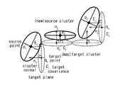
- FIG. 12 is an explanatory diagram illustrating a second example of self-position estimation of the mobile body 1A based on the first cluster group and the second cluster group.
- the self-position estimation unit 140A can estimate the self-position and posture of the mobile body 1A by matching the cluster groups with each other using the Symmetric ICP of the cluster group.
- the second example of self-position estimation is a suitable method when the surface of an object existing in the external environment is mainly a curved surface.
- the self-position estimation unit 140A defines the specifications of the cluster group as follows. p 1 , p 2 , ... p n : Center point of the source cluster group n 1 p , n 2 p , ... n n p : Normal of the source cluster group q 1 , q 2 , ... q n : Center of the target cluster group Point n 1 q , n 2 q , ... n n q : Normal of the target cluster group
- the self-position estimation unit 140A estimates R and t such that the loss function E shown by the following equation 9 is minimized. Since R, which is a rotation matrix, corresponds to the posture estimated by the moving body 1A, and t, which is a parallel traveling matrix, corresponds to the position estimated by the moving body 1A, the self-position estimation unit 140A estimates R and t. Therefore, the self-position and posture of the moving body 1A can be estimated.
- FIG. 13 is an explanatory diagram illustrating a third example of self-position estimation of the mobile body 1A based on the first cluster group and the second cluster group.
- the self-position estimation unit 140A can estimate the self-position and posture of the moving body 1A by matching the cluster groups with each other using the Point To Plane ICP in consideration of the covariance of the cluster groups.
- the third example of self-position estimation is a suitable method when the object surface existing in the external environment is mainly planar and has a large covariance.
- the self-position estimation unit 140A defines the specifications of the cluster group as follows. p 1 , p 2 , ... p n : Center point of the source cluster group q 1 , q 2 , ... q n : Center point of the target cluster group n 1 , n 2 , ... n n : Normal of the target cluster group C 1 , C 2 , ... C n : Covariance of the target cluster group
- the self-position estimation unit 140A estimates R and t such that the loss function E shown by the following mathematical formula 10 is minimized. Since R, which is a rotation matrix, corresponds to the posture estimated by the moving body 1A, and t, which is a parallel traveling matrix, corresponds to the position estimated by the moving body 1A, the self-position estimation unit 140A estimates R and t. Therefore, the self-position and posture of the moving body 1A can be estimated.
- FIG. 14 is an explanatory diagram illustrating a fourth example of self-position estimation of the mobile body 1A based on the first cluster group and the second cluster group.
- the self-position estimation unit 140A can estimate the self-position and posture of the moving body 1A by matching the cluster groups with each other using the Symmetric ICP in which the covariance of the cluster groups is taken into consideration.
- the fourth example of self-position estimation is a suitable method when the object surface existing in the external environment is mainly curved and has a large covariance.
- the self-position estimation unit 140A defines the specifications of the cluster group as follows. p 1 , p 2 , ... p n : Center point of the source cluster group n 1 p , n 2 p , ... n n p : Normal of the source cluster group C 1 p , C 2 p , ... C n p : Source cluster Group covariance q 1 , q 2 , ... q n : Center point of target cluster group n 1 q , n 2 q , ... n n q : Normal of target cluster group C 1 q , C 2 q , ... C n q : Co-distribution of target clusters
- the self-position estimation unit 140A estimates R and t such that the loss function E shown by the following equation 11 is minimized. Since R, which is a rotation matrix, corresponds to the posture estimated by the moving body 1A, and t, which is a parallel traveling matrix, corresponds to the position estimated by the moving body 1A, the self-position estimation unit 140A estimates R and t. Therefore, the self-position and posture of the moving body 1A can be estimated.
- the above matching method between cluster groups can also be performed in combination with each other. Further, even if the self-position estimation unit 140A estimates the self-position and posture of the moving body 1A by collectively performing the self-position estimation executed in the steps of S202 and S203 by using the method of Bundle Adjustment. good.
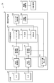
- FIG. 15 is a block diagram showing an example of the functional configuration of the mobile body 2 including the information processing apparatus 11 according to the present embodiment.
- the moving body 2 includes a sensor unit 20 including a plurality of sensors 21 and 22, an information processing device 11 according to the present embodiment, a drive control unit 31, and a moving mechanism 32.
- the information processing device 11 includes a plurality of plane estimation units 111 and 112, a plurality of coordinate system conversion units 161 and 162, a cluster group update unit 120A, an object recognition unit 130, a self-position estimation unit 140, and an action planning unit. It is equipped with 150.
- the object recognition unit 130, the self-position estimation unit 140, the action planning unit 150, the drive control unit 31, and the movement mechanism 32 are substantially the same as the configurations described in the first embodiment. The description here is omitted.
- the mobile body 2 including the information processing device 11 includes a sensor unit 20 including a plurality of sensors 21 and 22 that sense the environment around the mobile body 2.
- the sensor unit 20 includes a plurality of sensors 21 and 22 which are sensors of the same type or different types, and outputs a sensing result of the environment around the moving body 2 as point cloud data.
- the plurality of sensors 21 and 22 may be distance measuring sensors such as an ultrasonic sensor, a ToF sensor, a RADAR, or a LiDAR sensor, and may be a stereo camera, a monocular camera, a color camera, an infrared camera, or a spectroscopic camera. , Or an image pickup device such as a polarized camera.
- the plurality of sensors 21 and 22 may be a combination of one stereo camera system and one ToF sensor system.
- the point cloud data acquired by the plurality of sensors 21 and 22 are individually clustered by the plane estimation units 111 and 112, respectively, and then converted into the same coordinate system by the coordinate system conversion units 161 and 162. That is, the point cloud data acquired by the sensor 21 is converted into a cluster group by clustering in the plane estimation unit 111, and the coordinate system is converted into the coordinate system of the environment map by the coordinate system conversion unit 161. .. Further, the point cloud data acquired by the sensor 22 is converted into a cluster group by clustering in the plane estimation unit 112, and the coordinate system is converted into the coordinate system of the environment map by the coordinate system conversion unit 162. ..
- the coordinate system conversion units 161 and 162 are included in the cluster group based on the self-position of the moving body 2 in order to correct the positions of the sensors 21 and 22 that fluctuate with the movement of the moving body 2. Convert the position coordinates of each cluster to the coordinates relative to the environment map. Further, the coordinate system conversion units 161, 162 are the coordinate system of the cluster group based on the point cloud data acquired by each of the sensors 21 and 22 in order to correct the difference in the reference positions of the sensors 21 and 22 having different mounting positions. To the same coordinate system.
- the cluster group update unit 120A can sequentially fuse the cluster group in which the point cloud data output from the sensor unit 20 is clustered, regardless of the type of the sensor included in the sensor unit 20.
- the cluster group update unit 120A is different from the cluster group update unit 120 described in the first embodiment in that it further includes a sequencing unit 123.
- the sequencing unit 123 rearranges the first cluster group in which the point cloud data acquired by each of the sensors 21 and 22 is clustered in chronological order. Specifically, the sequencing unit 123 is the first based on the time when the point cloud data that is the basis of the first cluster group is acquired, regardless of whether it is acquired by the sensor 21 or 22. Sort the clusters in chronological order. According to this, the determination unit 121 and the fusion unit 122 in the subsequent stage of the sequencing unit 123 fuse the first cluster group reflecting the time change of the environment around the moving body 2 into the second cluster group in chronological order. It is possible to make it.
- the data of the first cluster group obtained by clustering the point cloud data acquired by the plurality of sensors 21 and 22 is separately input to the cluster group update unit 120A. Therefore, the information processing apparatus 11 is provided with a sequencing unit 123 that rearranges the first cluster group in chronological order across the plurality of sensors 21 and 22. According to this, the determination unit 121 and the fusion unit 122 in the subsequent stage of the sequencing unit 123 form the first cluster group in the order in which the sequencing unit 123 is rearranged, as described in the first embodiment.
- the second cluster group can be updated by fusing it with the cluster group of.
- determination unit 121 and the fusion unit 122 are substantially the same as the respective configurations described in the first embodiment, the description thereof is omitted here.
- the information processing apparatus 11 can reflect all the point cloud data acquired by the plurality of sensors 21 and 22 on the environment map showing the environment around the moving body 2, it has higher accuracy. It is possible to build an environmental map.
- FIG. 15 shows an example in which the sensor unit 20 includes two sensors 21 and 22, the technique according to the present embodiment is not limited to the above example. If the number of sensors included in the sensor unit 20 is 2 or more, the upper limit is not particularly specified.
- FIG. 16 is a block diagram showing an example of the functional configuration of the mobile body 2A including the information processing device 11A according to the present modification.
- the self-position estimation unit 140A has the first cluster group and the first cluster group, as in the information processing apparatus 10A according to the modified example of the first embodiment.
- the cluster group of 2 By further using the cluster group of 2, the self-position of the moving body 2A can be estimated with higher accuracy. Since the specific operation of the self-position estimation unit 140A is substantially the same as the modification of the first embodiment, detailed description thereof will be omitted here.
- FIG. 17 is a block diagram showing a hardware configuration example of the information processing devices 10, 10A, 11, 11A according to the present embodiment.
- the functions of the information processing devices 10, 10A, 11 and 11A according to the present embodiment are realized by the cooperation between the software and the hardware described below.
- the function may be executed by the CPU 901.
- the information processing devices 10, 10A, 11 and 11A include a CPU (Central Processing Unit) 901, a ROM (Read Only Memory) 903, and a RAM (Random Access Memory) 905.
- a CPU Central Processing Unit
- ROM Read Only Memory
- RAM Random Access Memory
- the information processing devices 10, 10A, 11 and 11A include a host bus 907, a bridge 909, an external bus 911, an interface 913, an input device 915, an output device 917, a storage device 919, a drive 921, a connection port 923, and a communication device. 925 may be further included. Further, the information processing devices 10, 10A, 11 and 11A may have other processing circuits such as a DSP (Digital Signal Processor) or an ASIC (Application Specific Integrated Circuit) in place of the CPU 901 or together with the CPU 901. ..
- DSP Digital Signal Processor
- ASIC Application Specific Integrated Circuit
- the CPU 901 functions as an arithmetic processing device or a control device, and controls the overall operation of the information processing devices 10, 10A, 11 and 11A according to various programs recorded in the ROM 903, the RAM 905, the storage device 919, or the removable recording medium 927. ..
- the ROM 903 stores programs used by the CPU 901, arithmetic parameters, and the like.
- the RAM 905 temporarily stores a program used in the execution of the CPU 901, a parameter used in the execution, and the like.
- the CPU 901, ROM 903, and RAM 905 are connected to each other by a host bus 907 composed of an internal bus such as a CPU bus. Further, the host bus 907 is connected to an external bus 911 such as a PCI (Peripheral Component Interconnect / Interface) bus via a bridge 909.
- a PCI Peripheral Component Interconnect / Interface
- the input device 915 is a device that receives input from a user such as a mouse, a keyboard, a touch panel, a button, a switch, or a lever.
- the input device 915 may be a microphone or the like that detects a user's voice. Further, the input device 915 may be, for example, a remote control device using infrared rays or other radio waves, or an externally connected device 929 corresponding to the operation of the information processing device 10.
- the input device 915 further includes an input control circuit that outputs an input signal generated based on the information input by the user to the CPU 901.
- an input control circuit that outputs an input signal generated based on the information input by the user to the CPU 901.
- the output device 917 is a device capable of visually or audibly presenting the information acquired or generated by the information processing devices 10, 10A, 11, 11A to the user.
- the output device 917 may be, for example, a display device such as an LCD (Liquid Crystal Display), a PDP (Plasma Display Panel), an OLED (Organic Light Emitting Display) display, a hologram, or a projector.
- the output device 917 may be a sound output device such as a speaker or headphones, or may be a printing device such as a printer device.
- the output device 917 may output the information obtained by the processing of the information processing devices 10, 10A, 11, 11A as a video such as a text or an image, or a sound such as voice or sound.
- the storage device 919 is a data storage device configured as an example of the storage units of the information processing devices 10, 10A, 11, and 11A.
- the storage device 919 may be configured by, for example, a magnetic storage device such as an HDD (Hard Disk Drive), a semiconductor storage device, an optical storage device, an optical magnetic storage device, or the like.
- the storage device 919 can store a program executed by the CPU 901, various data, various data acquired from the outside, and the like.
- the drive 921 is a read or write device for a removable recording medium 927 such as a magnetic disk, an optical disk, a magneto-optical disk, or a semiconductor memory, and is built in or externally attached to the information processing devices 10, 10A, 11, and 11A.
- the drive 921 can read the information recorded in the attached removable recording medium 927 and output it to the RAM 905. Further, the drive 921 can write a record on the removable recording medium 927 mounted on the drive 921.
- the connection port 923 is a port for directly connecting the external connection device 929 to the information processing devices 10, 10A, 11, 11A.
- the connection port 923 may be, for example, a USB (Universal Serial Bus) port, an IEEE1394 port, a SCSI (Small Computer System Interface) port, or the like. Further, the connection port 923 may be an RS-232C port, an optical audio terminal, an HDMI (registered trademark) (High-Definition Multidimedia Interface) port, or the like.
- the communication device 925 is, for example, a communication interface composed of a communication device for connecting to the communication network 931.
- the communication device 925 may be, for example, a communication card for a wired or wireless LAN (Local Area Network), Bluetooth (registered trademark), WUSB (Wireless USB), or the like. Further, the communication device 925 may be a router for optical communication, a router for ADSL (Asymmetric Digital Subscriber Line), a modem for various communications, or the like.
- the communication device 925 can send and receive signals and the like to and from the Internet or other communication devices using a predetermined protocol such as TCP / IP.
- the communication network 931 connected to the communication device 925 is a network connected by wire or wirelessly, and is, for example, an Internet communication network, a home LAN, an infrared communication network, a radio wave communication network, a satellite communication network, or the like. May be good.
- the techniques related to the present disclosure have been described above with reference to the first and second embodiments and modified examples.
- the technique according to the present disclosure is not limited to the above-described embodiment and the like, and various modifications can be made.
- the technique according to the present disclosure can be applied not only to a route plan in an environmental map of a three-dimensional space but also to a route plan in an environmental map of a two-dimensional plane.
- the information processing apparatus may include at least a fusion unit.
- the technology according to the present disclosure may have the following configuration. According to the technique according to the present disclosure having the following configuration, for example, by sequentially fusing a cluster group in which point cloud data acquired by a sensor is clustered into a cluster group generated in the past in chronological order, the surrounding clusters are fused. It is possible to sequentially update the cluster group corresponding to the microplane group of the object surface existing in the environment. Therefore, the technology according to the present disclosure can update the environmental map expressing the surrounding environment with higher efficiency.
- the effects exerted by the techniques according to the present disclosure are not necessarily limited to the effects described herein, and may be any of the effects described in the present disclosure.
- a fusion unit for updating the second cluster group by fusing to each of the second clusters included in the second cluster group generated based on the above is provided.
- the fusion portion is a weight based on the shape of the first cluster and the second cluster, the number of point clouds of the point cloud data used to generate the first cluster and the second cluster, or the first point cloud.
- the shapes of the first cluster and the second cluster are flat ellipsoids.
- the fusion section fuses each of the first clusters to each of the second clusters based on the normal direction of the flat ellipsoid and the thickness of the flat ellipsoid in the normal direction.
- the fusion unit estimates the shapes of the first cluster and the second cluster to be fused based on a Kalman filter.
- the shapes of the first cluster and the second cluster are flat ellipsoids.
- the determination unit is a fusion target for each of the first clusters based on the distance and angle in the normal direction of the flat ellipsoid with respect to the flat surface and the distance of the flat ellipsoid in the flat direction.
- the information processing apparatus according to (5) above which determines each of the second clusters.
- the first point cloud data is acquired by a plurality of sensors and is obtained.
- the fusion unit sequentially fuses a plurality of the first cluster groups obtained by clustering the first point cloud data acquired by the plurality of sensors into the second cluster group in chronological order.
- the information processing apparatus according to any one of (1) to (6).
- (8) The information processing apparatus according to (7) above, wherein the plurality of sensors include sensors of the same type or different types.
- the information processing apparatus according to (7) or (8) above, wherein the plurality of the first cluster groups are coordinate-converted to the same coordinate system.
- the sensor is mounted on a mobile body for which an action plan is created based on an environmental map.
- Information processing device (11)
- a self-position estimation unit for estimating the self-position of the moving body is provided.
- the information processing apparatus according to (10) above, wherein the coordinate conversion unit converts the position coordinates of the first cluster into the relative coordinates with respect to the environment map based on the estimated self-position of the moving body.
- the self-position estimation unit estimates the self-position of the mobile body based on the first cluster and the second cluster.
- the fusion unit discards the second cluster in which the first cluster has not been fused for a predetermined period or longer, and updates the second cluster group.
- the information processing apparatus according to any one of (1) to (12) above.
- the first point cloud data and the second point cloud data are data representing a three-dimensional space.
- the first cluster group is generated by clustering a partial point cloud obtained by dividing a point cloud included in the first point cloud data until a predetermined division condition is not satisfied, and the above (1) to (14). ) Is described in any one of the items.
- the predetermined division condition is a condition relating to the number of points included in the point cloud, a condition relating to the size of the area surrounding the point cloud, a condition relating to the density of the points included in the point cloud, or a condition relating to the shape of the point cloud.
- the information processing apparatus is a condition relating to the number of points included in the point cloud, a condition relating to the size of the region surrounding the point cloud, a condition relating to the density of the points included in the point cloud, or a condition relating to the shape of the point cloud.
- the information processing apparatus comprising at least one or more of the above.
- (19) Using an arithmetic processing unit, The second point cloud data acquired earlier than the first point cloud data for each of the first clusters included in the first cluster group in which the first point cloud data acquired by the sensor is clustered.
Landscapes
- Engineering & Computer Science (AREA)
- Physics & Mathematics (AREA)
- General Physics & Mathematics (AREA)
- Radar, Positioning & Navigation (AREA)
- Aviation & Aerospace Engineering (AREA)
- Remote Sensing (AREA)
- Automation & Control Theory (AREA)
- Theoretical Computer Science (AREA)
- Computer Vision & Pattern Recognition (AREA)
- General Engineering & Computer Science (AREA)
- Software Systems (AREA)
- Computer Hardware Design (AREA)
- Computer Graphics (AREA)
- Multimedia (AREA)
- Image Analysis (AREA)
- Traffic Control Systems (AREA)
- Control Of Position, Course, Altitude, Or Attitude Of Moving Bodies (AREA)
Priority Applications (2)
| Application Number | Priority Date | Filing Date | Title |
|---|---|---|---|
| JP2022534971A JP7715151B2 (ja) | 2020-07-08 | 2021-06-10 | 情報処理装置、情報処理方法、及びプログラム |
| US18/003,365 US12346122B2 (en) | 2020-07-08 | 2021-06-10 | Information processing apparatus and information processing method |
Applications Claiming Priority (2)
| Application Number | Priority Date | Filing Date | Title |
|---|---|---|---|
| JP2020-118065 | 2020-07-08 | ||
| JP2020118065 | 2020-07-08 |
Publications (1)
| Publication Number | Publication Date |
|---|---|
| WO2022009602A1 true WO2022009602A1 (ja) | 2022-01-13 |
Family
ID=79552486
Family Applications (1)
| Application Number | Title | Priority Date | Filing Date |
|---|---|---|---|
| PCT/JP2021/022191 Ceased WO2022009602A1 (ja) | 2020-07-08 | 2021-06-10 | 情報処理装置、情報処理方法、及びプログラム |
Country Status (3)
| Country | Link |
|---|---|
| US (1) | US12346122B2 (enExample) |
| JP (1) | JP7715151B2 (enExample) |
| WO (1) | WO2022009602A1 (enExample) |
Cited By (2)
| Publication number | Priority date | Publication date | Assignee | Title |
|---|---|---|---|---|
| CN116608837A (zh) * | 2022-02-08 | 2023-08-18 | 株式会社东芝 | 测量系统、测量方法以及存储介质 |
| WO2025023054A1 (ja) * | 2023-07-24 | 2025-01-30 | ソニーグループ株式会社 | 情報処理方法、情報処理装置および情報処理プログラム |
Families Citing this family (1)
| Publication number | Priority date | Publication date | Assignee | Title |
|---|---|---|---|---|
| US12117519B2 (en) * | 2021-10-07 | 2024-10-15 | Motional Ad Llc | Object detection using RADAR and LiDAR fusion |
Citations (6)
| Publication number | Priority date | Publication date | Assignee | Title |
|---|---|---|---|---|
| JP2013200604A (ja) * | 2012-03-23 | 2013-10-03 | Toyota Motor Corp | 移動ロボット |
| JP2014173869A (ja) * | 2013-03-06 | 2014-09-22 | Denso Wave Inc | 物体検出方法 |
| JP2017134514A (ja) * | 2016-01-26 | 2017-08-03 | トヨタ自動車株式会社 | 物体検出装置 |
| WO2018229812A1 (ja) * | 2017-06-12 | 2018-12-20 | 株式会社日立製作所 | 三次元計測装置、および方法 |
| JP2019168417A (ja) * | 2018-03-26 | 2019-10-03 | 株式会社デンソー | 物体認識装置、及び物体認識方法 |
| JP2020024618A (ja) * | 2018-08-08 | 2020-02-13 | 村田機械株式会社 | 移動経路取得方法、及び、移動経路取得装置 |
Family Cites Families (1)
| Publication number | Priority date | Publication date | Assignee | Title |
|---|---|---|---|---|
| US9128185B2 (en) * | 2012-03-15 | 2015-09-08 | GM Global Technology Operations LLC | Methods and apparatus of fusing radar/camera object data and LiDAR scan points |
-
2021
- 2021-06-10 US US18/003,365 patent/US12346122B2/en active Active
- 2021-06-10 JP JP2022534971A patent/JP7715151B2/ja active Active
- 2021-06-10 WO PCT/JP2021/022191 patent/WO2022009602A1/ja not_active Ceased
Patent Citations (6)
| Publication number | Priority date | Publication date | Assignee | Title |
|---|---|---|---|---|
| JP2013200604A (ja) * | 2012-03-23 | 2013-10-03 | Toyota Motor Corp | 移動ロボット |
| JP2014173869A (ja) * | 2013-03-06 | 2014-09-22 | Denso Wave Inc | 物体検出方法 |
| JP2017134514A (ja) * | 2016-01-26 | 2017-08-03 | トヨタ自動車株式会社 | 物体検出装置 |
| WO2018229812A1 (ja) * | 2017-06-12 | 2018-12-20 | 株式会社日立製作所 | 三次元計測装置、および方法 |
| JP2019168417A (ja) * | 2018-03-26 | 2019-10-03 | 株式会社デンソー | 物体認識装置、及び物体認識方法 |
| JP2020024618A (ja) * | 2018-08-08 | 2020-02-13 | 村田機械株式会社 | 移動経路取得方法、及び、移動経路取得装置 |
Cited By (3)
| Publication number | Priority date | Publication date | Assignee | Title |
|---|---|---|---|---|
| CN116608837A (zh) * | 2022-02-08 | 2023-08-18 | 株式会社东芝 | 测量系统、测量方法以及存储介质 |
| JP2023115721A (ja) * | 2022-02-08 | 2023-08-21 | 株式会社東芝 | 計測システム、計測方法及び計測プログラム |
| WO2025023054A1 (ja) * | 2023-07-24 | 2025-01-30 | ソニーグループ株式会社 | 情報処理方法、情報処理装置および情報処理プログラム |
Also Published As
| Publication number | Publication date |
|---|---|
| US20230244244A1 (en) | 2023-08-03 |
| JP7715151B2 (ja) | 2025-07-30 |
| US12346122B2 (en) | 2025-07-01 |
| JPWO2022009602A1 (enExample) | 2022-01-13 |
Similar Documents
| Publication | Publication Date | Title |
|---|---|---|
| CN111260751B (zh) | 基于多传感器移动机器人的建图方法 | |
| CN112639502B (zh) | 机器人位姿估计 | |
| CN111402339B (zh) | 一种实时定位方法、装置、系统及存储介质 | |
| CN107562048B (zh) | 一种基于激光雷达的动态避障控制方法 | |
| JP7131994B2 (ja) | 自己位置推定装置、自己位置推定方法、自己位置推定プログラム、学習装置、学習方法及び学習プログラム | |
| KR102694715B1 (ko) | 장애물의 검출 방법, 전자 기기, 노변 기기 및 클라우드 컨트롤 플랫폼 | |
| WO2022009602A1 (ja) | 情報処理装置、情報処理方法、及びプログラム | |
| JP2020530569A (ja) | 車両センサの較正及び位置特定 | |
| CN110663060B (zh) | 一种用于表示环境元素的方法、装置、系统、以及车辆/机器人 | |
| JP7138361B2 (ja) | 3次元仮想空間モデルを利用したユーザポーズ推定方法および装置 | |
| CN114527760A (zh) | 一种路径规划方法、系统、终端设备和存储介质 | |
| CN113936109A (zh) | 高精地图点云数据的处理方法、装置、设备以及存储介质 | |
| CN115371662B (zh) | 一种基于概率栅格移除动态对象的静态地图构建方法 | |
| CN117782050A (zh) | 鲁棒的激光-视觉-惯性融合slam方法 | |
| WO2021235100A1 (ja) | 情報処理装置、情報処理方法、及びプログラム | |
| CN113610702B (zh) | 一种建图方法、装置、电子设备及存储介质 | |
| CN108196258A (zh) | 外接设备的位置的确定方法及装置、虚拟现实设备及系统 | |
| CN114926549A (zh) | 三维点云处理方法、装置、设备以及存储介质 | |
| JP2009109200A (ja) | 位置姿勢推定システム、位置姿勢推定装置、および位置姿勢推定方法 | |
| WO2021131990A1 (ja) | 情報処理装置、情報処理方法、およびプログラム | |
| CN115200601A (zh) | 一种导航方法、装置、轮式机器人及存储介质 | |
| CN118189934B (zh) | 地图更新方法、装置、计算机设备和存储介质 | |
| JP7351609B2 (ja) | 経路探索装置及びプログラム | |
| WO2022246812A1 (zh) | 定位方法、装置、电子设备及存储介质 | |
| CN114694018A (zh) | 一种对象信息检测方法、装置和存储介质 |
Legal Events
| Date | Code | Title | Description |
|---|---|---|---|
| 121 | Ep: the epo has been informed by wipo that ep was designated in this application |
Ref document number: 21838179 Country of ref document: EP Kind code of ref document: A1 |
|
| ENP | Entry into the national phase |
Ref document number: 2022534971 Country of ref document: JP Kind code of ref document: A |
|
| NENP | Non-entry into the national phase |
Ref country code: DE |
|
| 122 | Ep: pct application non-entry in european phase |
Ref document number: 21838179 Country of ref document: EP Kind code of ref document: A1 |
|
| WWG | Wipo information: grant in national office |
Ref document number: 18003365 Country of ref document: US |