WO2022009602A1 - Information processing device, information processing method, and program - Google Patents
Information processing device, information processing method, and program Download PDFInfo
- Publication number
- WO2022009602A1 WO2022009602A1 PCT/JP2021/022191 JP2021022191W WO2022009602A1 WO 2022009602 A1 WO2022009602 A1 WO 2022009602A1 JP 2021022191 W JP2021022191 W JP 2021022191W WO 2022009602 A1 WO2022009602 A1 WO 2022009602A1
- Authority
- WO
- WIPO (PCT)
- Prior art keywords
- cluster
- point cloud
- information processing
- group
- unit
- Prior art date
Links
- 230000010365 information processing Effects 0.000 title claims abstract description 107
- 238000003672 processing method Methods 0.000 title claims description 7
- 230000004927 fusion Effects 0.000 claims description 62
- 238000006243 chemical reaction Methods 0.000 claims description 17
- 238000012545 processing Methods 0.000 claims description 12
- 230000007613 environmental effect Effects 0.000 claims description 8
- 230000009471 action Effects 0.000 claims description 3
- 238000000034 method Methods 0.000 description 23
- 238000010586 diagram Methods 0.000 description 20
- 238000004891 communication Methods 0.000 description 19
- 230000007246 mechanism Effects 0.000 description 17
- 230000004048 modification Effects 0.000 description 12
- 238000012986 modification Methods 0.000 description 12
- 230000006870 function Effects 0.000 description 11
- 230000010391 action planning Effects 0.000 description 9
- 239000011159 matrix material Substances 0.000 description 8
- 238000007499 fusion processing Methods 0.000 description 7
- 238000012163 sequencing technique Methods 0.000 description 7
- 230000003287 optical effect Effects 0.000 description 5
- 238000005259 measurement Methods 0.000 description 4
- 238000001514 detection method Methods 0.000 description 3
- 230000000694 effects Effects 0.000 description 3
- XLYOFNOQVPJJNP-UHFFFAOYSA-N water Substances O XLYOFNOQVPJJNP-UHFFFAOYSA-N 0.000 description 3
- 238000004364 calculation method Methods 0.000 description 2
- 238000005516 engineering process Methods 0.000 description 2
- 239000004065 semiconductor Substances 0.000 description 2
- 230000008859 change Effects 0.000 description 1
- 238000013500 data storage Methods 0.000 description 1
- 238000013461 design Methods 0.000 description 1
- 238000006073 displacement reaction Methods 0.000 description 1
- 239000004973 liquid crystal related substance Substances 0.000 description 1
- 238000013507 mapping Methods 0.000 description 1
- 230000002093 peripheral effect Effects 0.000 description 1
- 238000007639 printing Methods 0.000 description 1
- 230000004044 response Effects 0.000 description 1
Images


Classifications
-
- G—PHYSICS
- G05—CONTROLLING; REGULATING
- G05D—SYSTEMS FOR CONTROLLING OR REGULATING NON-ELECTRIC VARIABLES
- G05D1/00—Control of position, course or altitude of land, water, air, or space vehicles, e.g. automatic pilot
- G05D1/02—Control of position or course in two dimensions
- G05D1/021—Control of position or course in two dimensions specially adapted to land vehicles
- G05D1/0268—Control of position or course in two dimensions specially adapted to land vehicles using internal positioning means
- G05D1/0274—Control of position or course in two dimensions specially adapted to land vehicles using internal positioning means using mapping information stored in a memory device
-
- G—PHYSICS
- G06—COMPUTING; CALCULATING OR COUNTING
- G06T—IMAGE DATA PROCESSING OR GENERATION, IN GENERAL
- G06T19/00—Manipulating 3D models or images for computer graphics
-
- G—PHYSICS
- G06—COMPUTING; CALCULATING OR COUNTING
- G06T—IMAGE DATA PROCESSING OR GENERATION, IN GENERAL
- G06T7/00—Image analysis
-
- G—PHYSICS
- G06—COMPUTING; CALCULATING OR COUNTING
- G06T—IMAGE DATA PROCESSING OR GENERATION, IN GENERAL
- G06T7/00—Image analysis
- G06T7/20—Analysis of motion
- G06T7/277—Analysis of motion involving stochastic approaches, e.g. using Kalman filters
Definitions
- This disclosure relates to information processing devices, information processing methods, and programs.
- Non-Patent Document 1 a technique for expressing the surrounding environment as an aggregate of minute planes based on the sensing result by a sensor or the like has been proposed (for example, Non-Patent Document 1).
- a technique has been proposed in which the surface of an object existing in the surrounding environment is expressed as point group data by acquiring the distance and direction to an object existing in the surrounding environment with a distance measuring sensor or the like.
- each of the first clusters included in the first cluster group in which the first point cloud data acquired by the sensor is clustered is the first point cloud data.
- each of the first clusters included in the first cluster group in which the first point cloud data acquired by the sensor is clustered by using an arithmetic processing device is used.
- the second cluster is fused with each of the second clusters included in the second cluster group generated based on the second point cloud data acquired in the past than the first point cloud data. Includes updating the group.
- each of the first clusters included in the first cluster group in which the computer is clustered with the first point cloud data acquired by the sensor is subjected to the first point cloud.
- each cluster of the first cluster group based on the first point group data acquired by the sensor is referred to as the first point group data.
- the second cluster group can be updated by fusing with each cluster of the second cluster group based on the second point group data acquired in the past.
- the surrounding environment can be expressed by using the cluster group in which the point cloud data acquired by the sensor is compressed by clustering, and the cluster group is sequentially fused in chronological order to form the cluster group. Can be updated.
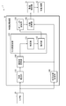
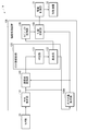
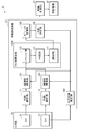
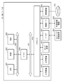
- FIG. 1 is a block diagram showing an example of the functional configuration of the mobile body 1 including the information processing apparatus 10 according to the present embodiment.
- the moving body 1 includes a sensor unit 20, an information processing device 10 according to the present embodiment, a drive control unit 31, and a moving mechanism 32. Further, the information processing apparatus 10 according to the present embodiment includes a plane estimation unit 110, a cluster group update unit 120, an object recognition unit 130, a self-position estimation unit 140, an action planning unit 150, and a coordinate system conversion unit 160. And.
- the moving body 1 is, for example, a robot or a drone that is provided with a moving mechanism 32 and can move autonomously.
- the information processing device 10 provided in the mobile body 1 constructs an environmental map based on the data acquired by the sensor unit 20, for example, and plans the movement route of the mobile body 1 based on the constructed environmental map. be able to.
- the movement path planned by the information processing apparatus 10 is output to, for example, a drive control unit 31 that controls the movement mechanism 32 of the moving body 1, so that the moving body 1 is moved along the planned moving path. Can be done.
- the information processing device 10 may be provided inside the mobile body 1, but it goes without saying that the information processing device 10 may be provided outside the mobile body 1.
- the information processing device 10 can output a route plan to the drive control unit 31 of the mobile body 1 via the internal wiring. Further, when the information processing device 10 is provided outside the mobile body 1, the information processing device 10 can transmit a route plan to the drive control unit 31 of the mobile body 1 via wireless communication or the like.
- the sensor unit 20 includes a sensor that senses the environment around the moving body 1, and outputs the sensing result as point cloud data that is a set of points.
- the sensor unit 20 is an ultrasonic sensor (Sound Navigation And Ringing: SONAR), a ToF (Time of Flyght) sensor, a RADAR (Radio Detection And Ringing), a LiDA (Light Detection And Range) sensor, or a LiDA (Light Detection) distance sensor. May include a range sensor to measure.
- the sensor unit 20 generates point cloud data by converting the measurement points into points in the three-dimensional coordinate system based on the information on the distance and orientation to the measurement points acquired from the distance measurement sensor. be able to.
- the sensor unit 20 may include an image pickup device that acquires an image of the surrounding environment of the moving body 1 such as a stereo camera, a monocular camera, a color camera, an infrared camera, a spectroscopic camera, or a polarized camera.
- the sensor unit 20 estimates the depth of the image points included in the captured image based on the captured image, and converts the image points into points in the three-dimensional coordinate system based on the information on the estimated depth. Then, the point cloud data can be generated.
- the sensor unit 20 may be provided in another device or object outside the moving body 1 as long as it can sense the environment around the moving body 1.
- the sensor unit 20 may be provided on the ceiling, wall, floor, or the like of the space in which the moving body 1 is present.
- the plane estimation unit 110 generates a cluster group by clustering the point cloud included in the point cloud data acquired by the sensor unit 20.
- the generated cluster group corresponds to the microplane group constituting the object surface existing around the moving body 1.
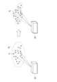
- FIG. 2 is an explanatory diagram illustrating point cloud data and clustering of point cloud data.
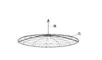
- FIG. 3 is an explanatory diagram schematically showing the shape of a cluster corresponding to a microplane constituting an object surface.
- the plane estimation unit 110 can generate a cluster group including a plurality of cluster CLs by clustering a point cloud PC which is a set of points P in a three-dimensional coordinate system.
- Each of the cluster CLs can be represented by a flat ellipsoid based on the center coordinates and the probability distribution shape of the cluster CLs, for example, as shown in FIG.
- the cluster CL may be represented by a flat ellipsoid whose center is the average value of the coordinates of the points included in the cluster CL and whose thickness is the covariance of the coordinates of the points included in the cluster CL.
- a vector NL indicating the thickness in the normal direction with respect to the flat plane and the thickness in the normal direction of the flat ellipsoid can be used as a representative parameter of the shape. That is, the plane estimation unit 110 can represent a microplane group constituting an object surface existing around the moving body 1 in a cluster group including a cluster represented by a flat ellipsoid.
- the plane estimation unit 110 divides the point cloud included in the point cloud data into a plurality of subpoint groups according to the following procedure, and clusters each of the divided subpoint groups to create an object.
- a cluster group corresponding to a microplane group constituting a surface may be generated.
- the plane estimation unit 110 first determines whether or not to divide the point cloud included in the point cloud data based on a predetermined division condition. When the point cloud satisfies a predetermined division condition, the plane estimation unit 110 divides the point cloud into substantially half and generates two partial point clouds. Next, the plane estimation unit 110 repeatedly divides the generated partial point cloud into substantially half until the above division condition is not satisfied. Subsequently, the plane estimation unit 110 determines whether or not to perform clustering for each of the partial point clouds divided until the above-mentioned division condition is not satisfied, based on a predetermined clustering condition. After that, the plane estimation unit 110 can generate a cluster group corresponding to the minute plane group constituting the object surface by performing clustering for each of the partial point groups satisfying a predetermined clustering condition.
- the above-mentioned predetermined division condition may include a condition that the number of points included in the point cloud is a predetermined number or more.
- the predetermined division condition is the length of the longest side of the rectangular parallelepiped region when the minimum rectangular parallelepiped region (also called a bounding box) containing all the points of the point group is set in the three-dimensional coordinate system. May include the condition that is greater than or equal to a predetermined length.
- the predetermined division condition may include a condition that the density of points in the point cloud is equal to or higher than a predetermined value.
- the density of points in the point cloud may be, for example, a value obtained by dividing the number of points included in the point cloud by the size of the above bounding box.
- the predetermined division condition may include a condition relating to the shape of the point cloud. Further, the predetermined division condition may include a condition in which a plurality of the above-mentioned conditions are combined.
- the predetermined clustering condition may include a condition that the number of points included in the point cloud is a predetermined number or more. Further, the predetermined clustering condition may include a condition that the length of the longest side of the bounding box is equal to or greater than the predetermined length. Further, the predetermined clustering condition may include a condition that the density of points in the above point cloud is equal to or higher than a predetermined value. Further, the predetermined clustering condition may include a condition relating to the shape of the point cloud. Further, the predetermined clustering condition may include a condition in which a plurality of the above-mentioned conditions are combined.
- the optimum conditions can be appropriately set based on the characteristics of the point cloud and the like.
- the plane estimation unit 110 performs clustering for each of the point clouds after the division until the predetermined division condition is not satisfied, the size of each of the point clouds to be clustered is reduced. be able to. Therefore, the plane estimation unit 110 can further shorten the clustering processing time. Further, since the plane estimation unit 110 can exclude a point cloud that does not satisfy a predetermined clustering condition and is likely to be inaccurate from the target of clustering, the accuracy of clustering can be further improved.
- the coordinate system conversion unit 160 converts the position coordinates of each cluster of the cluster group generated by the plane estimation unit 110 into relative coordinates with respect to the environment map. Specifically, the coordinate system conversion unit 160 converts the position coordinates of each cluster into relative coordinates to the environment map based on the self-position of the moving body 1 estimated by the self-position estimation unit 140 described later. For example, the position of the sensor unit 20 mounted on the moving body 1 changes as the moving body 1 moves. Therefore, the coordinate system conversion unit 160 sets the position coordinates of each cluster based on the point cloud data acquired by the sensor unit 20 based on the self-position of the moving body 1 on which the sensor unit 20 is mounted, as relative coordinates to the environment map. Convert to. As a result, the information processing apparatus 10 can handle the cluster group based on the point cloud data acquired by the sensor unit 20 on the same coordinates even when the position of the sensor unit 20 fluctuates.
- the cluster group update unit 120 updates the position and shape of each cluster of the cluster group corresponding to the microplane group constituting the object surface by using the point cloud data acquired by the sensor unit 20 at any time. Specifically, the cluster group updating unit 120 uses a cluster group (referred to as a first cluster group) in which the point group data (referred to as the first point group data) acquired by the sensor unit 20 is clustered. The second cluster is fused with the cluster group (second cluster group) generated based on the point group data (referred to as the second point group data) acquired in the past than the point group data of 1. The swarm may be updated.
- a cluster group referred to as a first cluster group
- the second cluster is fused with the cluster group (second cluster group) generated based on the point group data (referred to as the second point group data) acquired in the past than the point group data of 1.
- the swarm may be updated.
- the cluster group update unit 120 information-compresses the point cloud data acquired by the sensor unit 20 by clustering, and the information-compressed cluster group (first cluster group) is generated in the past (cluster group).
- the position and shape of each cluster in the second cluster group can be updated by sequentially fusing them into the second cluster group) in chronological order.
- the cluster group update unit 120 can use the cluster included in the cluster group as the data handling unit instead of the points included in the point cloud data, the amount of data to be handled and the amount of data calculation can be determined. Can be reduced. Therefore, the information processing apparatus 10 can more efficiently reflect the point cloud data acquired by the sensor unit 20 on the environment map.
- the cluster group update unit 120 includes the determination unit 121 and the fusion unit 122.
- the functions of the determination unit 121 and the fusion unit 122 will be described with reference to FIGS. 4 to 7.
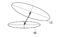
- FIG. 4 is an explanatory diagram illustrating an example of a method for determining a cluster to be fused.
- FIG. 5 is an explanatory diagram illustrating another example of a method for determining a cluster to be fused.
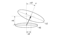
- FIG. 6 is an explanatory diagram illustrating a method of estimating the normal direction and the thickness of the first cluster and the second cluster to be fused.
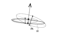
- FIG. 7 is an explanatory diagram showing the normal direction, the thickness, and the shape of the fusion cluster in which the first cluster and the second cluster are fused.
- each of the clusters represented by the flat ellipsoid as shown in FIG. 3 is represented by an elliptical shape which is a vertical cross section of the flat ellipsoid (that is, a cross-sectional view in the normal direction of the cluster).
- the determination unit 121 determines the combination of the cluster included in the first cluster group (referred to as the first cluster) and the cluster included in the second cluster group (referred to as the second cluster) to be fused.
- the determination unit 121 is based on the position and shape of the first cluster LC included in the first cluster group and the position and shape of the second cluster HC included in the second cluster group. , The combination of the first cluster LC to be fused and the second cluster HC may be determined. Specifically, the determination unit 121 has an angle n ⁇ formed by the normal directions with respect to the flat planes of the first cluster LC and the second cluster HC, and the normal directions of the first cluster LC and the second cluster HC. Normalized distance nd (distance normalized by cluster thickness) and normalized distance cd (cluster short diameter length) in the planodirectional direction of each of the first cluster LC and the second cluster HC. The combination of the first cluster LC and the second cluster HC to be fused may be determined based on the distance).
- the determination unit 121 fuses the first cluster LC and the second cluster HC in which the angle n ⁇ formed by the normal direction, the distance nd in the normal direction, and the distance cd in the flat plane direction are equal to or less than the respective threshold values. It may be determined that it is a combination of clusters. Alternatively, the determination unit 121 fuses the first cluster LC and the second cluster HC in which the angle n ⁇ formed by the normal direction, the distance nd in the normal direction, and the distance cd in the flat plane direction satisfy a predetermined relational expression. It may be determined as a combination of clusters of.
- the determination unit 121 is based on the normalized distance between the first cluster LC included in the first cluster group and the second cluster HC included in the second cluster group. , The combination of the first cluster LC to be fused and the second cluster HC may be determined. Specifically, the determination unit 121 may determine the combination of the first cluster LC and the second cluster HC to be fused based on the distance normalized by the covariance.
- the covariance-normalized distance (Mahalanobis distance (mahalanobis_distance)) is such that the center point of the first cluster LC is ⁇ j , the covariance of the first cluster LC is ⁇ j, and the center point of the second cluster HC is Assuming that the covariance of ⁇ i and the second cluster HC is ⁇ i , it can be shown by the following formula group 1.
- the determination unit 121 may determine one second cluster HC for a plurality of first cluster LCs as a cluster to be fused, as long as the determination condition of the cluster to be fused is satisfied.
- One first cluster LC may be determined as a cluster to be fused with respect to the second cluster HC.
- the second cluster HC does not have to have the first cluster LC determined to be the fusion target. As will be described later, the second cluster HC, which has not been determined to be the fusion target for the first cluster LC for a predetermined period or longer, is discarded when the second cluster group is updated by fusion with the first cluster group. May be good.
- the first cluster LC does not have to have the second cluster HC determined to be the fusion target. In such a case, the first cluster LC will be added to the second cluster group without being fused with the second cluster HC.
- the fusion unit 122 fuses the first cluster LC and the second cluster HC determined to be fusion targets based on the shapes of the first cluster LC and the second cluster HC.
- the fusion portion 122 has the thickness in the normal direction and the normal direction (also referred to as the normal direction and the thickness LNL of the first cluster LC) with respect to the flat surface of the first cluster LC, and the first.
- the normal direction and the thickness in the normal direction of the two cluster HC with respect to the flat plane also referred to as the normal direction and the thickness HNL of the second cluster HC
- the fusion unit 122 uses the normal direction and thickness LNL of the first cluster LC estimated with high accuracy and the normal direction and thickness HNL of the second cluster HC, and the first cluster LC and the second cluster. Fuse HC.
- the fusion unit 122 can estimate the normal direction and thickness LNL of the first cluster LC and the normal direction and thickness HNL of the second cluster HC with high accuracy by using a Kalman filter. ..
- the fusion unit 122 defines the specifications of the Kalman filter using the cluster components shown below, and the first cluster is based on the Kalman filter prediction equation shown in the equation group 2 and the Kalman filter update equation shown in the equation group 3.
- the normal direction and thickness LNL of LC and the normal direction and thickness HNL of the second cluster HC may be estimated.
- x t Normal vector of the second cluster HC ( ⁇ x ) 2 t : Thickness in the normal direction of the second cluster HC
- z t Normal vector of the first cluster LC
- ⁇ z 2 Normal of the first cluster LC Thickness in the direction ⁇ w 2 : System noise (hyper parameter)
- the fusion unit 122 is a cluster after fusion based on the estimated normal direction and thickness LNL of the first cluster LC and the normal direction and thickness HNL of the second cluster HC.
- the normal direction and thickness UNL of UC are derived.
- the fusion unit 122 is a cluster UC after fusion in which the first cluster LC included in the first cluster group and the second cluster HC included in the second cluster group are fused.
- the position and shape of the second cluster HC included in the two cluster groups can be updated.
- the fusion unit 122 may fuse the first cluster LC and the second cluster HC by a simple fusion process based on the cluster shape. For example, suppose that the center point of the first cluster LC is ⁇ j , the covariance of the first cluster LC is ⁇ j , the center point of the second cluster HC is ⁇ i , and the covariance of the second cluster HC is ⁇ i.
- the center point ⁇ merged and the covariance ⁇ merged of the subsequent cluster UC can be expressed by the following formula group 4.
- the fusion unit 122 may fuse the first cluster LC and the second cluster HC in a fusion process including a fusion cluster pair based on the cluster shape. For example, suppose that the center point of the first cluster LC is ⁇ j , the covariance of the first cluster LC is ⁇ j , the center point of the second cluster HC is ⁇ i , and the covariance of the second cluster HC is ⁇ i.
- the center point ⁇ merged and the covariance ⁇ merged of the subsequent cluster UC can be expressed by the following formula group 5.
- the fusion unit 122 may fuse the first cluster LC and the second cluster HC by the fusion process using the cluster weight. Specifically, the fusion unit 122 combines the first cluster LC and the second cluster HC with the number of point clouds in the point cloud data used to generate the first cluster group and the second cluster group as the cluster weight. May be fused. For example, suppose that the center point of the first cluster LC is ⁇ j , the covariance of the first cluster LC is ⁇ j , the center point of the second cluster HC is ⁇ i , and the covariance of the second cluster HC is ⁇ i. The center point ⁇ merged and the covariance ⁇ merged of the subsequent cluster UC can be expressed by the following formula group 6.
- w i is the first point number group in group data points used to generate the group clusters including a first cluster LC
- w j is the generation of the second group of clusters including a second cluster HC It is the number of point clouds in the point cloud data used in.
- the fusion unit 122 may fuse the first cluster LC and the second cluster HC by the fusion process using the cluster reliability. Specifically, the fusion unit 122 uses the reliability of the sensor unit 20 when acquiring the point cloud data used for generating the first cluster group and the second cluster group as the cluster weight as the first cluster.
- LC and the second cluster HC may be fused. For example, suppose that the center point of the first cluster LC is ⁇ j , the covariance of the first cluster LC is ⁇ j , the center point of the second cluster HC is ⁇ i , and the covariance of the second cluster HC is ⁇ i.
- the center point ⁇ merged and the covariance ⁇ merged of the subsequent cluster UC can be expressed by the following formula group 7.
- c i is a first group of clusters reliability when acquiring the data point group used for the generation of including the first cluster LC, c j, the second cluster including a second cluster HC It is the reliability when the point cloud data used for the generation of the group is acquired.
- the second cluster HC that was not the target of fusion with the first cluster LC is the second cluster until a predetermined period. You may keep it in the group. After that, the fusion unit 122 may discard the second cluster HC, which has not been the target of fusion of the first cluster LC for a predetermined period or longer, at the time of updating the second cluster group. Further, among the first cluster LCs included in the first cluster group, the fusion unit 122 adds the first cluster LC, which was not the target of fusion with the second cluster HC, to the second cluster group as it is. May be good.
- the object recognition unit 130 recognizes an object corresponding to the grouped one or a plurality of clusters by grouping one or a plurality of clusters included in the cluster group updated by the cluster group update unit 120.
- the object recognition unit 130 may recognize the objects existing around the moving body 1 based on the shape, arrangement, mutual spacing, and the like of each cluster included in the cluster group.
- the object recognition unit 130 exists around the moving body 1 by associating the shape and arrangement of each cluster included in the cluster group with the image captured by the image pickup device included in the sensor unit 20. You may recognize the object to be used.
- the object recognition unit 130 constructs an environment map expressing each of the clusters using the center coordinates and the probability distribution shape based on the recognized object.
- the object recognition unit 130 may construct an environment map of a two-dimensional plane or may construct an environment map of a three-dimensional space.
- the object recognition unit 130 reduces the amount of data in the environment map by constructing the environment map using clusters represented by flat ellipsoids, as compared with the case where the environment map is constructed using the so-called grid map. can do. According to this, the object recognition unit 130 can construct the environment map in a short time even with less computational resources.
- the self-position estimation unit 140 estimates the position of the mobile body 1 on the environment map based on the information about the environment around the mobile body 1 acquired by the sensor unit 20. Further, the self-position estimation unit 140 generates self-position data indicating the estimated position of the moving body 1 and outputs the self-position data to the coordinate system conversion unit 160 and the action planning unit 150.
- the self-position estimation unit 140 may estimate the position of the moving body 1 based on the sensing result of the sensor that measures the state of the moving body 1. For example, the self-position estimation unit 140 calculates the movement direction and the movement distance of the moving body 1 based on the sensing result of the encoder provided at each joint of the leg portion included in the moving mechanism 32 of the moving body 1. The position of the moving body 1 may be estimated. For example, the self-position estimation unit 140 calculates the moving direction and the moving distance of the moving body 1 based on the sensing result of the encoder provided on each wheel included in the moving mechanism 32 of the moving body 1. The position of may be estimated.
- the self-position estimation unit 140 has a moving direction and a moving distance of the moving body 1 based on the sensing result of an IMU (Inertial Measurement Unit) having a 3-axis gyro sensor and a 3-way accelerometer provided in the moving body 1. You may estimate the position of the moving body 1 by calculating.
- IMU Inertial Measurement Unit
- the self-position estimation unit 140 may estimate the position of the moving body 1 based on the information acquired by another sensor such as a GNSS (Global Navigation Satellite System) sensor.
- GNSS Global Navigation Satellite System
- the action planning unit 150 creates an action plan for the moving body 1 by grasping the situation around the moving body 1 based on the information acquired from the sensor unit 20 and the like. Specifically, the action planning unit 150 may plan a movement route to the destination of the moving body 1 based on the environment map around the moving body 1 and the self-position data of the moving body 1.
- the drive control unit 31 controls the drive of the movement mechanism 32 to move the moving body 1 along the movement path planned by the action planning unit 150.
- the drive control unit 31 has a movement mechanism 32 so that the difference between the position of the moving body 1 on the moving path planned by the action planning unit 150 at a predetermined time and the actual position of the moving body 1 becomes small.
- the moving body 1 may be moved along the moving path.
- the moving mechanism 32 is, for example, a mechanism that enables the moving body 1 to move on the ground, on the water, in the water, or in the air.
- the moving mechanism 32 is a moving mechanism that enables traveling on the ground such as two-wheeled or four-wheeled wheels, a moving mechanism that allows walking on the ground such as two-legged or four-legged legs, and an aerial vehicle such as a propeller or a rotary wing. It may be a moving mechanism that makes it possible to fly, or a moving mechanism that makes it possible to move on or under water such as a screw.
- the information processing apparatus 10 can compress the point cloud data that senses the surrounding environment by clustering, and express the surrounding environment by the information-compressed cluster group. can. According to this, the information processing apparatus 10 can reduce the amount of data to be handled and the calculation load.
- the information processing apparatus 10 by estimating the normal direction and thickness of the cluster by the Kalman filter, the clusters can be sequentially fused using the normal direction and thickness estimated with higher accuracy. can. According to this, the information processing apparatus 10 can create an environment map in which the environment around the mobile body 1 is expressed with higher accuracy.
- the information processing apparatus 10 can shorten the processing time of the recognition processing of the surrounding environment, so that the response speed of the mobile body 1 can be improved. Further, since the information processing apparatus 10 can improve the recognition accuracy for the surrounding environment, it is possible to plan an efficient movement route with a smaller margin for the objects existing in the surrounding environment.
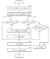
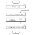
- FIG. 8 is a flowchart showing an example of the operation of the cluster group update unit 120.
- the determination unit 121 acquires the data of the first cluster group in which the point cloud data acquired by the sensor unit 20 is clustered (S101). Next, the determination unit 121 searches for and determines each of the first clusters included in the first cluster group to be fused and the second cluster included in the second cluster group (S102).
- the second cluster group is a cluster group generated in the past than the first cluster group. That is, the second cluster group is a cluster group generated by clustering the second point group data acquired in the past than the first point group data used for generating the first cluster group. Alternatively, it is a cluster group obtained by further updating the cluster group.
- the determination unit 121 determines whether or not there is a second cluster to be fused for each of the first clusters included in the first cluster group (S103).
- the first cluster (S103 / Yes) in which the second cluster to be fused exists is the first cluster to be fused in the cluster fusion process (S108) after the normal direction and thickness estimation (S107) described later. Fused with 2 clusters.
- the first cluster (S103 / No) in which the second cluster to be fused does not exist is directly added to the second cluster group in the step of cluster addition (S109).
- the determination unit 121 determines whether or not there is a first cluster to be fused for each of the second clusters included in the second cluster group (S104).
- the second cluster (S104 / Yes) in which the first cluster to be fused exists is the first cluster to be fused in the subsequent cluster fusion process (S108) after estimating the normal direction and thickness (S107). It is fused with one cluster.
- the second cluster (S104 / No) in which the first cluster to be fused does not exist is out of the fusion target for a predetermined time or longer (S105).
- the second cluster is out of the fusion target for a predetermined period or more (S105 / Yes)
- the corresponding second cluster is discarded (S106).
- the second cluster is out of the fusion target for less than a predetermined period, the corresponding second cluster is not destroyed and is directly added to the second cluster group in the step of cluster addition (S109).
- the fusion unit 122 uses a Kalman filter to estimate the normal direction and thickness of the first cluster and the second cluster to be fused (S107).
- the fusion unit 122 fuses the first cluster and the second cluster based on the estimated normal direction and thickness (S108).
- the fusion unit 122 updates the second cluster group by adding the first cluster and the second cluster that bypassed the fusion process to the second cluster after fusion (S109).
- the cluster group update unit 120 newly acquires the first cluster group in which the point cloud data newly acquired by the sensor unit 20 is clustered (S101), and repeatedly executes the update of the second cluster group. ..
- the information processing apparatus 10 can improve the recognition accuracy of the surrounding environment by sequentially fusing the clusters representing the surrounding environment in chronological order.
- FIG. 9 is a block diagram showing an example of the functional configuration of the mobile body 1A including the information processing apparatus 10A according to the present modification.
- the self-position estimation unit 140A further uses the first cluster group and the second cluster group to obtain the self-position of the moving body 1A. Estimates can be made with higher accuracy. Specifically, the self-position estimation unit 140A may estimate the self-position of the moving body 1A based on the flowchart shown in FIG. FIG. 10 is a flowchart showing a flow of estimating the self-position of the moving body 1A by the self-position estimation unit 140A.
- the self-position estimation unit 140A sets the reference of the map coordinates of the environment map (S201). Specifically, the self-position estimation unit 140 may estimate the initial position of the moving body 1A from the absolute coordinates on the earth acquired by the GNSS sensor, and may use the absolute coordinates of the moving body 1A as the reference of the map coordinates. (Earth center coordinate system). Alternatively, the self-position estimation unit 140A may use the initial position of the moving body 1A as a zero point as a reference for map coordinates (relative coordinate system).
- the self-position estimation unit 140A estimates the self-position and posture of the moving body 1A based on the sensing result of, for example, IMU (S202). Specifically, the self-position estimation unit 140A uses the sensing result of the IMU during the period until the sensor unit 20 acquires the point cloud data based on the position and posture of the initial position of the moving body 1A. The self-position and posture of 1A may be estimated. Alternatively, the self-position estimation unit 140A uses the IMU sensing result of the displacement from time t-1 to time t with reference to the position and posture of the moving body 1A at the time (time t-1) one time before. The self-position and posture of the moving body 1A may be estimated.
- the self-position estimation unit 140A may estimate the self-position and posture of the moving body 1A by using the moving amount of the moving body 1A estimated from the encoder or the like included in the moving mechanism 32 of the moving body 1. Further, the self-position estimation unit 140A may correct the result of the self-position estimation by using the geomagnetic data or the GNSS data.
- the self-position estimation unit 140A estimates the self-position of the mobile body 1A using the cluster group with the position and posture (time t) of the mobile body 1A estimated in S202 as initial values (S203). Specifically, the self-position estimation unit 140A uses the first cluster group based on the point cloud data acquired at time t as the source, and targets the second cluster group that has been fused and processed one time before, as the cluster group. By matching each other, the self-position and posture of the moving body 1A can be estimated with higher accuracy. After that, the self-position estimation unit 140A outputs the self-position and posture of the moving body 1A at the time t estimated with high accuracy (S204).
- the self-position estimation unit 140A may skip the self-position estimation step (S202) using the IMU and execute only the self-position estimation step (S203) using the cluster group. In such a case, the self-position estimation unit 140A may use the position and posture of the moving body 1A at the time (time t-1) one time before as the initial value of the self-position estimation using the cluster group.
- FIG. 11 is an explanatory diagram illustrating a first example of self-position estimation of the mobile body 1A based on the first cluster group and the second cluster group.
- the self-position estimation unit 140A can estimate the self-position and posture of the moving body 1A by matching the cluster groups with each other using the Point To Plane ICP of the cluster group.
- the first example of self-position estimation is a suitable method when the surface of an object existing in the external environment is composed mainly of planes.
- the self-position estimation unit 140A defines the specifications of the cluster group as follows. p 1 , p 2 , ... p n : Center point of the source cluster group q 1 , q 2 , ... q n : Center point of the target cluster group n 1 , n 2 , ... n n : Normal of the target cluster group
- the self-position estimation unit 140A estimates R and t such that the loss function E shown by the following equation 8 is minimized. Since R, which is a rotation matrix, corresponds to the posture estimated by the moving body 1A, and t, which is a parallel traveling matrix, corresponds to the position estimated by the moving body 1A, the self-position estimation unit 140A estimates R and t. Therefore, the self-position and posture of the moving body 1A can be estimated.
- FIG. 12 is an explanatory diagram illustrating a second example of self-position estimation of the mobile body 1A based on the first cluster group and the second cluster group.
- the self-position estimation unit 140A can estimate the self-position and posture of the mobile body 1A by matching the cluster groups with each other using the Symmetric ICP of the cluster group.
- the second example of self-position estimation is a suitable method when the surface of an object existing in the external environment is mainly a curved surface.
- the self-position estimation unit 140A defines the specifications of the cluster group as follows. p 1 , p 2 , ... p n : Center point of the source cluster group n 1 p , n 2 p , ... n n p : Normal of the source cluster group q 1 , q 2 , ... q n : Center of the target cluster group Point n 1 q , n 2 q , ... n n q : Normal of the target cluster group
- the self-position estimation unit 140A estimates R and t such that the loss function E shown by the following equation 9 is minimized. Since R, which is a rotation matrix, corresponds to the posture estimated by the moving body 1A, and t, which is a parallel traveling matrix, corresponds to the position estimated by the moving body 1A, the self-position estimation unit 140A estimates R and t. Therefore, the self-position and posture of the moving body 1A can be estimated.
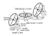
- FIG. 13 is an explanatory diagram illustrating a third example of self-position estimation of the mobile body 1A based on the first cluster group and the second cluster group.
- the self-position estimation unit 140A can estimate the self-position and posture of the moving body 1A by matching the cluster groups with each other using the Point To Plane ICP in consideration of the covariance of the cluster groups.
- the third example of self-position estimation is a suitable method when the object surface existing in the external environment is mainly planar and has a large covariance.
- the self-position estimation unit 140A defines the specifications of the cluster group as follows. p 1 , p 2 , ... p n : Center point of the source cluster group q 1 , q 2 , ... q n : Center point of the target cluster group n 1 , n 2 , ... n n : Normal of the target cluster group C 1 , C 2 , ... C n : Covariance of the target cluster group
- the self-position estimation unit 140A estimates R and t such that the loss function E shown by the following mathematical formula 10 is minimized. Since R, which is a rotation matrix, corresponds to the posture estimated by the moving body 1A, and t, which is a parallel traveling matrix, corresponds to the position estimated by the moving body 1A, the self-position estimation unit 140A estimates R and t. Therefore, the self-position and posture of the moving body 1A can be estimated.
- FIG. 14 is an explanatory diagram illustrating a fourth example of self-position estimation of the mobile body 1A based on the first cluster group and the second cluster group.
- the self-position estimation unit 140A can estimate the self-position and posture of the moving body 1A by matching the cluster groups with each other using the Symmetric ICP in which the covariance of the cluster groups is taken into consideration.
- the fourth example of self-position estimation is a suitable method when the object surface existing in the external environment is mainly curved and has a large covariance.
- the self-position estimation unit 140A defines the specifications of the cluster group as follows. p 1 , p 2 , ... p n : Center point of the source cluster group n 1 p , n 2 p , ... n n p : Normal of the source cluster group C 1 p , C 2 p , ... C n p : Source cluster Group covariance q 1 , q 2 , ... q n : Center point of target cluster group n 1 q , n 2 q , ... n n q : Normal of target cluster group C 1 q , C 2 q , ... C n q : Co-distribution of target clusters
- the self-position estimation unit 140A estimates R and t such that the loss function E shown by the following equation 11 is minimized. Since R, which is a rotation matrix, corresponds to the posture estimated by the moving body 1A, and t, which is a parallel traveling matrix, corresponds to the position estimated by the moving body 1A, the self-position estimation unit 140A estimates R and t. Therefore, the self-position and posture of the moving body 1A can be estimated.
- the above matching method between cluster groups can also be performed in combination with each other. Further, even if the self-position estimation unit 140A estimates the self-position and posture of the moving body 1A by collectively performing the self-position estimation executed in the steps of S202 and S203 by using the method of Bundle Adjustment. good.
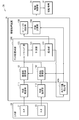
- FIG. 15 is a block diagram showing an example of the functional configuration of the mobile body 2 including the information processing apparatus 11 according to the present embodiment.
- the moving body 2 includes a sensor unit 20 including a plurality of sensors 21 and 22, an information processing device 11 according to the present embodiment, a drive control unit 31, and a moving mechanism 32.
- the information processing device 11 includes a plurality of plane estimation units 111 and 112, a plurality of coordinate system conversion units 161 and 162, a cluster group update unit 120A, an object recognition unit 130, a self-position estimation unit 140, and an action planning unit. It is equipped with 150.
- the object recognition unit 130, the self-position estimation unit 140, the action planning unit 150, the drive control unit 31, and the movement mechanism 32 are substantially the same as the configurations described in the first embodiment. The description here is omitted.
- the mobile body 2 including the information processing device 11 includes a sensor unit 20 including a plurality of sensors 21 and 22 that sense the environment around the mobile body 2.
- the sensor unit 20 includes a plurality of sensors 21 and 22 which are sensors of the same type or different types, and outputs a sensing result of the environment around the moving body 2 as point cloud data.
- the plurality of sensors 21 and 22 may be distance measuring sensors such as an ultrasonic sensor, a ToF sensor, a RADAR, or a LiDAR sensor, and may be a stereo camera, a monocular camera, a color camera, an infrared camera, or a spectroscopic camera. , Or an image pickup device such as a polarized camera.
- the plurality of sensors 21 and 22 may be a combination of one stereo camera system and one ToF sensor system.
- the point cloud data acquired by the plurality of sensors 21 and 22 are individually clustered by the plane estimation units 111 and 112, respectively, and then converted into the same coordinate system by the coordinate system conversion units 161 and 162. That is, the point cloud data acquired by the sensor 21 is converted into a cluster group by clustering in the plane estimation unit 111, and the coordinate system is converted into the coordinate system of the environment map by the coordinate system conversion unit 161. .. Further, the point cloud data acquired by the sensor 22 is converted into a cluster group by clustering in the plane estimation unit 112, and the coordinate system is converted into the coordinate system of the environment map by the coordinate system conversion unit 162. ..
- the coordinate system conversion units 161 and 162 are included in the cluster group based on the self-position of the moving body 2 in order to correct the positions of the sensors 21 and 22 that fluctuate with the movement of the moving body 2. Convert the position coordinates of each cluster to the coordinates relative to the environment map. Further, the coordinate system conversion units 161, 162 are the coordinate system of the cluster group based on the point cloud data acquired by each of the sensors 21 and 22 in order to correct the difference in the reference positions of the sensors 21 and 22 having different mounting positions. To the same coordinate system.
- the cluster group update unit 120A can sequentially fuse the cluster group in which the point cloud data output from the sensor unit 20 is clustered, regardless of the type of the sensor included in the sensor unit 20.
- the cluster group update unit 120A is different from the cluster group update unit 120 described in the first embodiment in that it further includes a sequencing unit 123.
- the sequencing unit 123 rearranges the first cluster group in which the point cloud data acquired by each of the sensors 21 and 22 is clustered in chronological order. Specifically, the sequencing unit 123 is the first based on the time when the point cloud data that is the basis of the first cluster group is acquired, regardless of whether it is acquired by the sensor 21 or 22. Sort the clusters in chronological order. According to this, the determination unit 121 and the fusion unit 122 in the subsequent stage of the sequencing unit 123 fuse the first cluster group reflecting the time change of the environment around the moving body 2 into the second cluster group in chronological order. It is possible to make it.
- the data of the first cluster group obtained by clustering the point cloud data acquired by the plurality of sensors 21 and 22 is separately input to the cluster group update unit 120A. Therefore, the information processing apparatus 11 is provided with a sequencing unit 123 that rearranges the first cluster group in chronological order across the plurality of sensors 21 and 22. According to this, the determination unit 121 and the fusion unit 122 in the subsequent stage of the sequencing unit 123 form the first cluster group in the order in which the sequencing unit 123 is rearranged, as described in the first embodiment.
- the second cluster group can be updated by fusing it with the cluster group of.
- determination unit 121 and the fusion unit 122 are substantially the same as the respective configurations described in the first embodiment, the description thereof is omitted here.
- the information processing apparatus 11 can reflect all the point cloud data acquired by the plurality of sensors 21 and 22 on the environment map showing the environment around the moving body 2, it has higher accuracy. It is possible to build an environmental map.
- FIG. 15 shows an example in which the sensor unit 20 includes two sensors 21 and 22, the technique according to the present embodiment is not limited to the above example. If the number of sensors included in the sensor unit 20 is 2 or more, the upper limit is not particularly specified.
- FIG. 16 is a block diagram showing an example of the functional configuration of the mobile body 2A including the information processing device 11A according to the present modification.
- the self-position estimation unit 140A has the first cluster group and the first cluster group, as in the information processing apparatus 10A according to the modified example of the first embodiment.
- the cluster group of 2 By further using the cluster group of 2, the self-position of the moving body 2A can be estimated with higher accuracy. Since the specific operation of the self-position estimation unit 140A is substantially the same as the modification of the first embodiment, detailed description thereof will be omitted here.
- FIG. 17 is a block diagram showing a hardware configuration example of the information processing devices 10, 10A, 11, 11A according to the present embodiment.
- the functions of the information processing devices 10, 10A, 11 and 11A according to the present embodiment are realized by the cooperation between the software and the hardware described below.
- the function may be executed by the CPU 901.
- the information processing devices 10, 10A, 11 and 11A include a CPU (Central Processing Unit) 901, a ROM (Read Only Memory) 903, and a RAM (Random Access Memory) 905.
- a CPU Central Processing Unit
- ROM Read Only Memory
- RAM Random Access Memory
- the information processing devices 10, 10A, 11 and 11A include a host bus 907, a bridge 909, an external bus 911, an interface 913, an input device 915, an output device 917, a storage device 919, a drive 921, a connection port 923, and a communication device. 925 may be further included. Further, the information processing devices 10, 10A, 11 and 11A may have other processing circuits such as a DSP (Digital Signal Processor) or an ASIC (Application Specific Integrated Circuit) in place of the CPU 901 or together with the CPU 901. ..
- DSP Digital Signal Processor
- ASIC Application Specific Integrated Circuit
- the CPU 901 functions as an arithmetic processing device or a control device, and controls the overall operation of the information processing devices 10, 10A, 11 and 11A according to various programs recorded in the ROM 903, the RAM 905, the storage device 919, or the removable recording medium 927. ..
- the ROM 903 stores programs used by the CPU 901, arithmetic parameters, and the like.
- the RAM 905 temporarily stores a program used in the execution of the CPU 901, a parameter used in the execution, and the like.
- the CPU 901, ROM 903, and RAM 905 are connected to each other by a host bus 907 composed of an internal bus such as a CPU bus. Further, the host bus 907 is connected to an external bus 911 such as a PCI (Peripheral Component Interconnect / Interface) bus via a bridge 909.
- a PCI Peripheral Component Interconnect / Interface
- the input device 915 is a device that receives input from a user such as a mouse, a keyboard, a touch panel, a button, a switch, or a lever.
- the input device 915 may be a microphone or the like that detects a user's voice. Further, the input device 915 may be, for example, a remote control device using infrared rays or other radio waves, or an externally connected device 929 corresponding to the operation of the information processing device 10.
- the input device 915 further includes an input control circuit that outputs an input signal generated based on the information input by the user to the CPU 901.
- an input control circuit that outputs an input signal generated based on the information input by the user to the CPU 901.
- the output device 917 is a device capable of visually or audibly presenting the information acquired or generated by the information processing devices 10, 10A, 11, 11A to the user.
- the output device 917 may be, for example, a display device such as an LCD (Liquid Crystal Display), a PDP (Plasma Display Panel), an OLED (Organic Light Emitting Display) display, a hologram, or a projector.
- the output device 917 may be a sound output device such as a speaker or headphones, or may be a printing device such as a printer device.
- the output device 917 may output the information obtained by the processing of the information processing devices 10, 10A, 11, 11A as a video such as a text or an image, or a sound such as voice or sound.
- the storage device 919 is a data storage device configured as an example of the storage units of the information processing devices 10, 10A, 11, and 11A.
- the storage device 919 may be configured by, for example, a magnetic storage device such as an HDD (Hard Disk Drive), a semiconductor storage device, an optical storage device, an optical magnetic storage device, or the like.
- the storage device 919 can store a program executed by the CPU 901, various data, various data acquired from the outside, and the like.
- the drive 921 is a read or write device for a removable recording medium 927 such as a magnetic disk, an optical disk, a magneto-optical disk, or a semiconductor memory, and is built in or externally attached to the information processing devices 10, 10A, 11, and 11A.
- the drive 921 can read the information recorded in the attached removable recording medium 927 and output it to the RAM 905. Further, the drive 921 can write a record on the removable recording medium 927 mounted on the drive 921.
- the connection port 923 is a port for directly connecting the external connection device 929 to the information processing devices 10, 10A, 11, 11A.
- the connection port 923 may be, for example, a USB (Universal Serial Bus) port, an IEEE1394 port, a SCSI (Small Computer System Interface) port, or the like. Further, the connection port 923 may be an RS-232C port, an optical audio terminal, an HDMI (registered trademark) (High-Definition Multidimedia Interface) port, or the like.
- the communication device 925 is, for example, a communication interface composed of a communication device for connecting to the communication network 931.
- the communication device 925 may be, for example, a communication card for a wired or wireless LAN (Local Area Network), Bluetooth (registered trademark), WUSB (Wireless USB), or the like. Further, the communication device 925 may be a router for optical communication, a router for ADSL (Asymmetric Digital Subscriber Line), a modem for various communications, or the like.
- the communication device 925 can send and receive signals and the like to and from the Internet or other communication devices using a predetermined protocol such as TCP / IP.
- the communication network 931 connected to the communication device 925 is a network connected by wire or wirelessly, and is, for example, an Internet communication network, a home LAN, an infrared communication network, a radio wave communication network, a satellite communication network, or the like. May be good.
- the techniques related to the present disclosure have been described above with reference to the first and second embodiments and modified examples.
- the technique according to the present disclosure is not limited to the above-described embodiment and the like, and various modifications can be made.
- the technique according to the present disclosure can be applied not only to a route plan in an environmental map of a three-dimensional space but also to a route plan in an environmental map of a two-dimensional plane.
- the information processing apparatus may include at least a fusion unit.
- the technology according to the present disclosure may have the following configuration. According to the technique according to the present disclosure having the following configuration, for example, by sequentially fusing a cluster group in which point cloud data acquired by a sensor is clustered into a cluster group generated in the past in chronological order, the surrounding clusters are fused. It is possible to sequentially update the cluster group corresponding to the microplane group of the object surface existing in the environment. Therefore, the technology according to the present disclosure can update the environmental map expressing the surrounding environment with higher efficiency.
- the effects exerted by the techniques according to the present disclosure are not necessarily limited to the effects described herein, and may be any of the effects described in the present disclosure.
- a fusion unit for updating the second cluster group by fusing to each of the second clusters included in the second cluster group generated based on the above is provided.
- the fusion portion is a weight based on the shape of the first cluster and the second cluster, the number of point clouds of the point cloud data used to generate the first cluster and the second cluster, or the first point cloud.
- the shapes of the first cluster and the second cluster are flat ellipsoids.
- the fusion section fuses each of the first clusters to each of the second clusters based on the normal direction of the flat ellipsoid and the thickness of the flat ellipsoid in the normal direction.
- the fusion unit estimates the shapes of the first cluster and the second cluster to be fused based on a Kalman filter.
- the shapes of the first cluster and the second cluster are flat ellipsoids.
- the determination unit is a fusion target for each of the first clusters based on the distance and angle in the normal direction of the flat ellipsoid with respect to the flat surface and the distance of the flat ellipsoid in the flat direction.
- the information processing apparatus according to (5) above which determines each of the second clusters.
- the first point cloud data is acquired by a plurality of sensors and is obtained.
- the fusion unit sequentially fuses a plurality of the first cluster groups obtained by clustering the first point cloud data acquired by the plurality of sensors into the second cluster group in chronological order.
- the information processing apparatus according to any one of (1) to (6).
- (8) The information processing apparatus according to (7) above, wherein the plurality of sensors include sensors of the same type or different types.
- the information processing apparatus according to (7) or (8) above, wherein the plurality of the first cluster groups are coordinate-converted to the same coordinate system.
- the sensor is mounted on a mobile body for which an action plan is created based on an environmental map.
- Information processing device (11)
- a self-position estimation unit for estimating the self-position of the moving body is provided.
- the information processing apparatus according to (10) above, wherein the coordinate conversion unit converts the position coordinates of the first cluster into the relative coordinates with respect to the environment map based on the estimated self-position of the moving body.
- the self-position estimation unit estimates the self-position of the mobile body based on the first cluster and the second cluster.
- the fusion unit discards the second cluster in which the first cluster has not been fused for a predetermined period or longer, and updates the second cluster group.
- the information processing apparatus according to any one of (1) to (12) above.
- the first point cloud data and the second point cloud data are data representing a three-dimensional space.
- the first cluster group is generated by clustering a partial point cloud obtained by dividing a point cloud included in the first point cloud data until a predetermined division condition is not satisfied, and the above (1) to (14). ) Is described in any one of the items.
- the predetermined division condition is a condition relating to the number of points included in the point cloud, a condition relating to the size of the area surrounding the point cloud, a condition relating to the density of the points included in the point cloud, or a condition relating to the shape of the point cloud.
- the information processing apparatus is a condition relating to the number of points included in the point cloud, a condition relating to the size of the region surrounding the point cloud, a condition relating to the density of the points included in the point cloud, or a condition relating to the shape of the point cloud.
- the information processing apparatus comprising at least one or more of the above.
- (19) Using an arithmetic processing unit, The second point cloud data acquired earlier than the first point cloud data for each of the first clusters included in the first cluster group in which the first point cloud data acquired by the sensor is clustered.
Abstract
This information processing device comprises a fusing unit that updates a second cluster group by fusing each first cluster included in a first cluster group obtained by clustering first point group data acquired by a sensor to each second cluster included in the second cluster group which is generated on the basis of second point group data acquired more in the past than the first point group data.
Description
本開示は、情報処理装置、情報処理方法、及びプログラムに関する。
This disclosure relates to information processing devices, information processing methods, and programs.
近年、センサ等によるセンシング結果に基づいて、周囲の環境を微小平面の集合体として表現する技術が提案されている(例えば、非特許文献1)。
In recent years, a technique for expressing the surrounding environment as an aggregate of minute planes based on the sensing result by a sensor or the like has been proposed (for example, Non-Patent Document 1).
例えば、測距センサ等によって周囲の環境に存在するオブジェクトまでの距離及び方位を取得することで、周囲の環境に存在するオブジェクト表面を点群データとして表現する技術が提案されている。
For example, a technique has been proposed in which the surface of an object existing in the surrounding environment is expressed as point group data by acquiring the distance and direction to an object existing in the surrounding environment with a distance measuring sensor or the like.
このような周囲の環境を表現するデータは、周囲の環境の変化に伴って迅速に更新されていくことが望まれる。
It is hoped that the data expressing such surrounding environment will be updated promptly as the surrounding environment changes.
よって、環境を表現したデータをより高効率で更新することが可能な、情報処理装置、情報処理方法、及びプログラムを提供することが望ましい。
Therefore, it is desirable to provide an information processing device, an information processing method, and a program that can update the data expressing the environment with higher efficiency.
本開示の一実施形態に係る情報処理装置は、センサにて取得された第1の点群データをクラスタリングした第1のクラスタ群に含まれる第1クラスタの各々を、前記第1の点群データよりも過去に取得された第2の点群データに基づいて生成された第2のクラスタ群に含まれる第2クラスタの各々に融合させることで、前記第2のクラスタ群を更新する融合部を備える。
In the information processing apparatus according to the embodiment of the present disclosure, each of the first clusters included in the first cluster group in which the first point cloud data acquired by the sensor is clustered is the first point cloud data. A fusion unit that updates the second cluster group by fusing to each of the second clusters included in the second cluster group generated based on the second point cloud data acquired in the past. Be prepared.
本開示の一実施形態に係る情報処理方法は、演算処理装置を用いて、センサにて取得された第1の点群データをクラスタリングした第1のクラスタ群に含まれる第1クラスタの各々を、前記第1の点群データよりも過去に取得された第2の点群データに基づいて生成された第2のクラスタ群に含まれる第2クラスタの各々に融合させることで、前記第2のクラスタ群を更新することを含む。
In the information processing method according to the embodiment of the present disclosure, each of the first clusters included in the first cluster group in which the first point cloud data acquired by the sensor is clustered by using an arithmetic processing device is used. The second cluster is fused with each of the second clusters included in the second cluster group generated based on the second point cloud data acquired in the past than the first point cloud data. Includes updating the group.
本開示の一実施形態に係るプログラムは、コンピュータを、センサにて取得された第1の点群データをクラスタリングした第1のクラスタ群に含まれる第1クラスタの各々を、前記第1の点群データよりも過去に取得された第2の点群データに基づいて生成された第2のクラスタ群に含まれる第2クラスタの各々に融合させることで、前記第2のクラスタ群を更新する融合部として機能させる。
In the program according to the embodiment of the present disclosure, each of the first clusters included in the first cluster group in which the computer is clustered with the first point cloud data acquired by the sensor is subjected to the first point cloud. A fusion unit that updates the second cluster group by fusing to each of the second clusters included in the second cluster group generated based on the second point cloud data acquired in the past rather than the data. To function as.
本開示の一実施形態に係る情報処理装置、情報処理方法、及プログラムでは、センサにて取得された第1の点群データに基づく第1のクラスタ群の各クラスタを、第1の点群データよりも過去に取得された第2の点群データに基づく第2のクラスタ群の各クラスタに融合させることで、第2のクラスタ群を更新することができる。これにより、例えば、センサにて取得された点群データをクラスタリングにて情報圧縮したクラスタ群を用いて周囲の環境を表現することができると共に、時系列にクラスタ群を順次融合させることでクラスタ群を更新することができる。
In the information processing apparatus, information processing method, and program according to the embodiment of the present disclosure, each cluster of the first cluster group based on the first point group data acquired by the sensor is referred to as the first point group data. The second cluster group can be updated by fusing with each cluster of the second cluster group based on the second point group data acquired in the past. As a result, for example, the surrounding environment can be expressed by using the cluster group in which the point cloud data acquired by the sensor is compressed by clustering, and the cluster group is sequentially fused in chronological order to form the cluster group. Can be updated.
以下、本開示における実施形態について、図面を参照して詳細に説明する。以下で説明する実施形態は本開示の一具体例であって、本開示にかかる技術が以下の態様に限定されるわけではない。また、本開示の各構成要素の配置、寸法、及び寸法比等についても、各図に示す様態に限定されるわけではない。
Hereinafter, embodiments in the present disclosure will be described in detail with reference to the drawings. The embodiments described below are specific examples of the present disclosure, and the technique according to the present disclosure is not limited to the following aspects. Further, the arrangement, dimensions, dimensional ratio, etc. of each component of the present disclosure are not limited to the modes shown in the respective figures.
なお、説明は以下の順序で行う。
1.第1の実施形態
1.1.構成例
1.2.動作例
1.3.変形例
2.第2の実施形態
2.1.構成例
2.2.変形例
3.ハードウェア構成例 The explanation will be given in the following order.
1. 1. First Embodiment 1.1. Configuration example 1.2. Operation example 1.3. Modification example 2. Second embodiment 2.1. Configuration example 2.2. Modification example 3. Hardware configuration example
<1.第1の実施形態>
(1.1.構成例)
まず、図1を参照して、本開示の第1の実施形態に係る情報処理装置を備える移動体について説明する。図1は、本実施形態に係る情報処理装置10を備える移動体1の機能構成の一例を示すブロック図である。 <1. First Embodiment>
(1.1. Configuration example)
First, with reference to FIG. 1, a mobile body including the information processing apparatus according to the first embodiment of the present disclosure will be described. FIG. 1 is a block diagram showing an example of the functional configuration of themobile body 1 including the information processing apparatus 10 according to the present embodiment.
(1.1.構成例)
まず、図1を参照して、本開示の第1の実施形態に係る情報処理装置を備える移動体について説明する。図1は、本実施形態に係る情報処理装置10を備える移動体1の機能構成の一例を示すブロック図である。 <1. First Embodiment>
(1.1. Configuration example)
First, with reference to FIG. 1, a mobile body including the information processing apparatus according to the first embodiment of the present disclosure will be described. FIG. 1 is a block diagram showing an example of the functional configuration of the
図1に示すように、移動体1は、センサ部20と、本実施形態に係る情報処理装置10と、駆動制御部31と、移動機構32とを備える。また、本実施形態に係る情報処理装置10は、平面推定部110と、クラスタ群更新部120と、オブジェクト認識部130と、自己位置推定部140と、行動計画部150と、座標系変換部160とを備える。
As shown in FIG. 1, the moving body 1 includes a sensor unit 20, an information processing device 10 according to the present embodiment, a drive control unit 31, and a moving mechanism 32. Further, the information processing apparatus 10 according to the present embodiment includes a plane estimation unit 110, a cluster group update unit 120, an object recognition unit 130, a self-position estimation unit 140, an action planning unit 150, and a coordinate system conversion unit 160. And.
移動体1は、例えば、移動機構32を備え、自律的に移動可能なロボット又はドローンなどである。移動体1に備えられた情報処理装置10は、例えば、センサ部20にて取得されたデータに基づいて環境地図を構築し、構築された環境地図に基づいて移動体1の移動経路を計画することができる。情報処理装置10にて計画された移動経路は、例えば、移動体1の移動機構32を制御する駆動制御部31に出力されることで、移動体1を計画した移動経路に沿って移動させることができる。
The moving body 1 is, for example, a robot or a drone that is provided with a moving mechanism 32 and can move autonomously. The information processing device 10 provided in the mobile body 1 constructs an environmental map based on the data acquired by the sensor unit 20, for example, and plans the movement route of the mobile body 1 based on the constructed environmental map. be able to. The movement path planned by the information processing apparatus 10 is output to, for example, a drive control unit 31 that controls the movement mechanism 32 of the moving body 1, so that the moving body 1 is moved along the planned moving path. Can be done.
情報処理装置10は、移動体1の内部に備えられてもよいが、移動体1の外部に備えられてもよいことは言うまでもない。情報処理装置10が移動体1の内部に備えられる場合、情報処理装置10は、内部配線を介して移動体1の駆動制御部31に経路計画を出力することができる。また、情報処理装置10が移動体1の外部に備えられる場合、情報処理装置10は、無線通信等を介して移動体1の駆動制御部31に経路計画を送信することができる。
The information processing device 10 may be provided inside the mobile body 1, but it goes without saying that the information processing device 10 may be provided outside the mobile body 1. When the information processing device 10 is provided inside the mobile body 1, the information processing device 10 can output a route plan to the drive control unit 31 of the mobile body 1 via the internal wiring. Further, when the information processing device 10 is provided outside the mobile body 1, the information processing device 10 can transmit a route plan to the drive control unit 31 of the mobile body 1 via wireless communication or the like.
センサ部20は、移動体1の周囲の環境をセンシングするセンサを含み、センシング結果を点の集合である点群データとして出力する。
The sensor unit 20 includes a sensor that senses the environment around the moving body 1, and outputs the sensing result as point cloud data that is a set of points.
例えば、センサ部20は、超音波センサ(Sound Navigation And Ranging:SONAR)、ToF(Time of Flight)センサ、RADAR(Radio Detecting And Ranging)、又はLiDAR(Light Detection And Ranging)センサなどの対象までの距離を測定する測距センサを含んでもよい。このような場合、センサ部20は、測距センサから取得された測定点までの距離及び方位に関する情報に基づいて測定点を三次元座標系における点に変換することで、点群データを生成することができる。
For example, the sensor unit 20 is an ultrasonic sensor (Sound Navigation And Ringing: SONAR), a ToF (Time of Flyght) sensor, a RADAR (Radio Detection And Ringing), a LiDA (Light Detection And Range) sensor, or a LiDA (Light Detection) distance sensor. May include a range sensor to measure. In such a case, the sensor unit 20 generates point cloud data by converting the measurement points into points in the three-dimensional coordinate system based on the information on the distance and orientation to the measurement points acquired from the distance measurement sensor. be able to.
または、センサ部20は、ステレオカメラ、単眼カメラ、カラーカメラ、赤外線カメラ、分光カメラ、又は偏光カメラなどの移動体1の周囲の環境の画像を取得する撮像装置を含んでもよい。このような場合、センサ部20は、撮像画像に基づいて撮像画像に含まれる画像点の深度を推定し、推定された深度に関する情報に基づいて画像点を三次元座標系における点に変換することで、点群データを生成することができる。
Alternatively, the sensor unit 20 may include an image pickup device that acquires an image of the surrounding environment of the moving body 1 such as a stereo camera, a monocular camera, a color camera, an infrared camera, a spectroscopic camera, or a polarized camera. In such a case, the sensor unit 20 estimates the depth of the image points included in the captured image based on the captured image, and converts the image points into points in the three-dimensional coordinate system based on the information on the estimated depth. Then, the point cloud data can be generated.
なお、センサ部20は、移動体1の周囲の環境をセンシングすることができれば、移動体1の外部の他の装置又はオブジェクト等に備えられてもよい。例えば、センサ部20は、移動体1が存在する空間の天井、壁、又は床等に備えられてもよい。
The sensor unit 20 may be provided in another device or object outside the moving body 1 as long as it can sense the environment around the moving body 1. For example, the sensor unit 20 may be provided on the ceiling, wall, floor, or the like of the space in which the moving body 1 is present.
平面推定部110は、センサ部20にて取得された点群データに含まれる点群をクラスタリングすることでクラスタ群を生成する。生成されたクラスタ群は、移動体1の周囲に存在するオブジェクト表面を構成する微小平面群に対応する。
The plane estimation unit 110 generates a cluster group by clustering the point cloud included in the point cloud data acquired by the sensor unit 20. The generated cluster group corresponds to the microplane group constituting the object surface existing around the moving body 1.
図2及び図3を参照して、点群データのクラスタリング、及びクラスタ群に含まれるクラスタについてより具体的に説明する。図2は、点群データ、及び点群データのクラスタリングについて説明する説明図である。図3は、オブジェクト表面を構成する微小平面に対応するクラスタの形状を模式的に示す説明図である。
With reference to FIGS. 2 and 3, clustering of point cloud data and clusters included in the cluster group will be described more specifically. FIG. 2 is an explanatory diagram illustrating point cloud data and clustering of point cloud data. FIG. 3 is an explanatory diagram schematically showing the shape of a cluster corresponding to a microplane constituting an object surface.
例えば、平面推定部110は、図2に示すように、三次元座標系における点Pの集合である点群PCをクラスタリングすることで、複数のクラスタCLを含むクラスタ群を生成することができる。クラスタCLの各々は、例えば、図3に示すように、クラスタCLの中心座標及び確率分布形状に基づいた扁平楕円体にて表現され得る。具体的には、クラスタCLは、クラスタCLに含まれる点の座標の平均値を中心とし、クラスタCLに含まれる点の座標の共分散を厚みとする扁平楕円体にて表現されてもよい。このような扁平楕円体のクラスタCLは、扁平面に対する法線方向、及び扁平楕円体の法線方向の厚みを示すベクトルNLを形状の代表的なパラメータとすることができる。すなわち、平面推定部110は、扁平楕円体で表現されるクラスタを含むクラスタ群にて、移動体1の周囲に存在するオブジェクト表面を構成する微小平面群を表現することができる。
For example, as shown in FIG. 2, the plane estimation unit 110 can generate a cluster group including a plurality of cluster CLs by clustering a point cloud PC which is a set of points P in a three-dimensional coordinate system. Each of the cluster CLs can be represented by a flat ellipsoid based on the center coordinates and the probability distribution shape of the cluster CLs, for example, as shown in FIG. Specifically, the cluster CL may be represented by a flat ellipsoid whose center is the average value of the coordinates of the points included in the cluster CL and whose thickness is the covariance of the coordinates of the points included in the cluster CL. In such a cluster CL of a flat ellipsoid, a vector NL indicating the thickness in the normal direction with respect to the flat plane and the thickness in the normal direction of the flat ellipsoid can be used as a representative parameter of the shape. That is, the plane estimation unit 110 can represent a microplane group constituting an object surface existing around the moving body 1 in a cluster group including a cluster represented by a flat ellipsoid.
より具体的には、平面推定部110は、以下の手順に従って、点群データに含まれる点群を複数の部分点群に分割し、分割した部分点群の各々についてクラスタリングを行うことで、オブジェクト表面を構成する微小平面群に対応するクラスタ群を生成してもよい。
More specifically, the plane estimation unit 110 divides the point cloud included in the point cloud data into a plurality of subpoint groups according to the following procedure, and clusters each of the divided subpoint groups to create an object. A cluster group corresponding to a microplane group constituting a surface may be generated.
具体的には、平面推定部110は、まず、所定の分割条件に基づいて、点群データに含まれる点群の分割を行うか否かを判定する。点群が所定の分割条件を満たす場合、平面推定部110は、点群を略半分に分割し、2つの部分点群を生成する。次に、平面推定部110は、生成された部分点群について、上記の分割条件を満たさなくなるまで部分点群を繰り返し略半分に分割する。続いて、平面推定部110は、所定のクラスタリング条件に基づいて、上記の分割条件を満たさなくなるまで分割された部分点群の各々について、クラスタリングを行うか否かを判定する。その後、平面推定部110は、所定のクラスタリング条件を満たす部分点群の各々に対してクラスタリングを行うことで、オブジェクト表面を構成する微小平面群に対応するクラスタ群を生成することができる。
Specifically, the plane estimation unit 110 first determines whether or not to divide the point cloud included in the point cloud data based on a predetermined division condition. When the point cloud satisfies a predetermined division condition, the plane estimation unit 110 divides the point cloud into substantially half and generates two partial point clouds. Next, the plane estimation unit 110 repeatedly divides the generated partial point cloud into substantially half until the above division condition is not satisfied. Subsequently, the plane estimation unit 110 determines whether or not to perform clustering for each of the partial point clouds divided until the above-mentioned division condition is not satisfied, based on a predetermined clustering condition. After that, the plane estimation unit 110 can generate a cluster group corresponding to the minute plane group constituting the object surface by performing clustering for each of the partial point groups satisfying a predetermined clustering condition.
ここで、上記の所定の分割条件は、点群に含まれる点の数が所定の数以上であるという条件を含んでもよい。また、所定の分割条件は、三次元座標系にて点群の全ての点を内包する最小の直方体領域(バウンディングボックスとも称される)を設定した際に、直方体領域の最も長い辺の長さが所定の長さ以上であるという条件を含んでもよい。また、所定の分割条件は、点群における点の密度が所定の値以上であるという条件を含んでもよい。点群における点の密度は、例えば、点群に含まれる点の数を上記のバウンディングボックスの大きさで除算した値としてもよい。また、所定の分割条件は、点群の形状に関する条件を含んでもよい。さらに、所定の分割条件は、上述した条件を複数組み合わせた条件を含んでもよい。
Here, the above-mentioned predetermined division condition may include a condition that the number of points included in the point cloud is a predetermined number or more. In addition, the predetermined division condition is the length of the longest side of the rectangular parallelepiped region when the minimum rectangular parallelepiped region (also called a bounding box) containing all the points of the point group is set in the three-dimensional coordinate system. May include the condition that is greater than or equal to a predetermined length. Further, the predetermined division condition may include a condition that the density of points in the point cloud is equal to or higher than a predetermined value. The density of points in the point cloud may be, for example, a value obtained by dividing the number of points included in the point cloud by the size of the above bounding box. Further, the predetermined division condition may include a condition relating to the shape of the point cloud. Further, the predetermined division condition may include a condition in which a plurality of the above-mentioned conditions are combined.
また、所定のクラスタリング条件とは、点群に含まれる点の数が所定の数以上であるという条件を含んでもよい。また、所定のクラスタリング条件は、上記のバウンディングボックスの最も長い辺の長さが所定の長さ以上であるという条件を含んでもよい。また、所定のクラスタリング条件は、上記の点群における点の密度が所定の値以上であるという条件を含んでもよい。また、所定のクラスタリング条件は、点群の形状に関する条件を含んでもよい。さらに、所定のクラスタリング条件は、上述した条件を複数組み合わせた条件を含んでもよい。
Further, the predetermined clustering condition may include a condition that the number of points included in the point cloud is a predetermined number or more. Further, the predetermined clustering condition may include a condition that the length of the longest side of the bounding box is equal to or greater than the predetermined length. Further, the predetermined clustering condition may include a condition that the density of points in the above point cloud is equal to or higher than a predetermined value. Further, the predetermined clustering condition may include a condition relating to the shape of the point cloud. Further, the predetermined clustering condition may include a condition in which a plurality of the above-mentioned conditions are combined.
なお、所定の分割条件、及び所定のクラスタリング条件は、点群の特性等に基づいてそれぞれ最適な条件が適宜設定され得る。
As for the predetermined division condition and the predetermined clustering condition, the optimum conditions can be appropriately set based on the characteristics of the point cloud and the like.
これによれば、平面推定部110は、所定の分割条件を満たさなくなるまで分割した後の点群の各々に対してクラスタリングを行うため、クラスタリングの対象となる点群の各々の大きさを小さくすることができる。したがって、平面推定部110は、クラスタリングの処理時間をより短縮することができる。また、平面推定部110は、所定のクラスタリング条件を満たさず、不正確である可能性が高い点群をクラスタリングの対象から外すことができるため、クラスタリングの精度をより高めることができる。
According to this, since the plane estimation unit 110 performs clustering for each of the point clouds after the division until the predetermined division condition is not satisfied, the size of each of the point clouds to be clustered is reduced. be able to. Therefore, the plane estimation unit 110 can further shorten the clustering processing time. Further, since the plane estimation unit 110 can exclude a point cloud that does not satisfy a predetermined clustering condition and is likely to be inaccurate from the target of clustering, the accuracy of clustering can be further improved.
座標系変換部160は、平面推定部110にて生成されたクラスタ群の各クラスタの位置座標を環境地図に対する相対座標に変換する。具体的には、座標系変換部160は、後述する自己位置推定部140にて推定される移動体1の自己位置に基づいて、各クラスタの位置座標を環境地図に対する相対座標に変換する。例えば、移動体1に搭載されたセンサ部20は、移動体1の移動に伴って位置が変動する。そのため、座標系変換部160は、センサ部20が搭載された移動体1の自己位置に基づいて、センサ部20にて取得された点群データに基づく各クラスタの位置座標を環境地図に対する相対座標に変換する。これにより、情報処理装置10は、センサ部20の位置が変動する場合でも、センサ部20にて取得された点群データに基づくクラスタ群を同一座標上で扱うことが可能となる。
The coordinate system conversion unit 160 converts the position coordinates of each cluster of the cluster group generated by the plane estimation unit 110 into relative coordinates with respect to the environment map. Specifically, the coordinate system conversion unit 160 converts the position coordinates of each cluster into relative coordinates to the environment map based on the self-position of the moving body 1 estimated by the self-position estimation unit 140 described later. For example, the position of the sensor unit 20 mounted on the moving body 1 changes as the moving body 1 moves. Therefore, the coordinate system conversion unit 160 sets the position coordinates of each cluster based on the point cloud data acquired by the sensor unit 20 based on the self-position of the moving body 1 on which the sensor unit 20 is mounted, as relative coordinates to the environment map. Convert to. As a result, the information processing apparatus 10 can handle the cluster group based on the point cloud data acquired by the sensor unit 20 on the same coordinates even when the position of the sensor unit 20 fluctuates.
クラスタ群更新部120は、センサ部20にて随時取得される点群データを用いて、オブジェクト表面を構成する微小平面群に対応するクラスタ群の各クラスタの位置及び形状を更新する。具体的には、クラスタ群更新部120は、センサ部20にて取得された点群データ(第1の点群データと称する)をクラスタリングしたクラスタ群(第1のクラスタ群と称する)を、第1の点群データよりも過去に取得された点群データ(第2の点群データと称する)に基づいて生成されたクラスタ群(第2のクラスタ群)に融合させることで、第2のクラスタ群を更新してもよい。
The cluster group update unit 120 updates the position and shape of each cluster of the cluster group corresponding to the microplane group constituting the object surface by using the point cloud data acquired by the sensor unit 20 at any time. Specifically, the cluster group updating unit 120 uses a cluster group (referred to as a first cluster group) in which the point group data (referred to as the first point group data) acquired by the sensor unit 20 is clustered. The second cluster is fused with the cluster group (second cluster group) generated based on the point group data (referred to as the second point group data) acquired in the past than the point group data of 1. The swarm may be updated.
すなわち、クラスタ群更新部120は、センサ部20にて取得された点群データをクラスタリングにて情報圧縮し、情報圧縮されたクラスタ群(第1のクラスタ群)を過去に生成されたクラスタ群(第2のクラスタ群)に時系列で順次融合させることで、第2のクラスタ群の各クラスタの位置及び形状を更新することができる。
That is, the cluster group update unit 120 information-compresses the point cloud data acquired by the sensor unit 20 by clustering, and the information-compressed cluster group (first cluster group) is generated in the past (cluster group). The position and shape of each cluster in the second cluster group can be updated by sequentially fusing them into the second cluster group) in chronological order.
これによれば、クラスタ群更新部120は、点群データに含まれる点ではなく、クラスタ群に含まれるクラスタをデータの取り扱い単位とすることができるため、取り扱うデータ量、及びデータの演算量を低減することができる。したがって、情報処理装置10は、センサ部20にて取得された点群データをより高効率に環境地図に反映することができる。
According to this, since the cluster group update unit 120 can use the cluster included in the cluster group as the data handling unit instead of the points included in the point cloud data, the amount of data to be handled and the amount of data calculation can be determined. Can be reduced. Therefore, the information processing apparatus 10 can more efficiently reflect the point cloud data acquired by the sensor unit 20 on the environment map.
より具体的には、クラスタ群更新部120は、判定部121、及び融合部122を含む。以下では、図4~図7を参照して、判定部121及び融合部122の機能について説明する。図4は、融合対象となるクラスタを判定する方法の一例を説明する説明図である。図5は、融合対象となるクラスタを判定する方法の他の例を説明する説明図である。図6は、融合対象となる第1クラスタ及び第2クラスタの法線方向及び厚みを推定する方法を説明する説明図である。図7は、第1クラスタ及び第2クラスタを融合した融合クラスタの法線方向及び厚み、並びに形状を示す説明図である。図4~図7では、図3で示すような扁平楕円体で表現されるクラスタの各々を扁平楕円体の縦断面(すなわち、クラスタの法線方向の断面図)である楕円形状にて表す。
More specifically, the cluster group update unit 120 includes the determination unit 121 and the fusion unit 122. Hereinafter, the functions of the determination unit 121 and the fusion unit 122 will be described with reference to FIGS. 4 to 7. FIG. 4 is an explanatory diagram illustrating an example of a method for determining a cluster to be fused. FIG. 5 is an explanatory diagram illustrating another example of a method for determining a cluster to be fused. FIG. 6 is an explanatory diagram illustrating a method of estimating the normal direction and the thickness of the first cluster and the second cluster to be fused. FIG. 7 is an explanatory diagram showing the normal direction, the thickness, and the shape of the fusion cluster in which the first cluster and the second cluster are fused. In FIGS. 4 to 7, each of the clusters represented by the flat ellipsoid as shown in FIG. 3 is represented by an elliptical shape which is a vertical cross section of the flat ellipsoid (that is, a cross-sectional view in the normal direction of the cluster).
判定部121は、第1のクラスタ群に含まれるクラスタ(第1クラスタと称する)と、第2のクラスタ群に含まれるクラスタ(第2クラスタと称する)との融合対象となる組み合わせを判定する。
The determination unit 121 determines the combination of the cluster included in the first cluster group (referred to as the first cluster) and the cluster included in the second cluster group (referred to as the second cluster) to be fused.
図4に示すように、判定部121は、第1のクラスタ群に含まれる第1クラスタLCの位置及び形状と、第2のクラスタ群に含まれる第2クラスタHCの位置及び形状とに基づいて、融合対象となる第1クラスタLCと、第2クラスタHCとの組み合わせを判定してもよい。具体的には、判定部121は、第1クラスタLC及び第2クラスタHCの各々の扁平面に対する法線方向がなす角度nθと、第1クラスタLC及び第2クラスタHCの各々の法線方向の正規化された距離nd(クラスタ厚みで正規化された距離)と、第1クラスタLC及び第2クラスタHCの各々の扁平面方向の正規化された距離cd(クラスタ短径長さで正規化された距離)とに基づいて、融合対象となる第1クラスタLCと、第2クラスタHCとの組み合わせを判定してもよい。
As shown in FIG. 4, the determination unit 121 is based on the position and shape of the first cluster LC included in the first cluster group and the position and shape of the second cluster HC included in the second cluster group. , The combination of the first cluster LC to be fused and the second cluster HC may be determined. Specifically, the determination unit 121 has an angle nθ formed by the normal directions with respect to the flat planes of the first cluster LC and the second cluster HC, and the normal directions of the first cluster LC and the second cluster HC. Normalized distance nd (distance normalized by cluster thickness) and normalized distance cd (cluster short diameter length) in the planodirectional direction of each of the first cluster LC and the second cluster HC. The combination of the first cluster LC and the second cluster HC to be fused may be determined based on the distance).
例えば、判定部121は、法線方向がなす角度nθ、法線方向の距離nd、及び扁平面方向の距離cdが各々の閾値以下である第1クラスタLCと、第2クラスタHCとを融合対象のクラスタの組み合わせと判定してもよい。または、判定部121は、法線方向がなす角度nθ、法線方向の距離nd、及び扁平面方向の距離cdが所定の関係式を満たす第1クラスタLCと、第2クラスタHCとを融合対象のクラスタの組み合わせと判定してもよい。
For example, the determination unit 121 fuses the first cluster LC and the second cluster HC in which the angle nθ formed by the normal direction, the distance nd in the normal direction, and the distance cd in the flat plane direction are equal to or less than the respective threshold values. It may be determined that it is a combination of clusters. Alternatively, the determination unit 121 fuses the first cluster LC and the second cluster HC in which the angle nθ formed by the normal direction, the distance nd in the normal direction, and the distance cd in the flat plane direction satisfy a predetermined relational expression. It may be determined as a combination of clusters of.
また、図5に示すように、判定部121は、第1のクラスタ群に含まれる第1クラスタLCと、第2のクラスタ群に含まれる第2クラスタHCとの正規化された距離に基づいて、融合対象となる第1クラスタLCと、第2クラスタHCとの組み合わせを判定してもよい。具体的には、判定部121は、共分散で正規化された距離に基づいて、融合対象となる第1クラスタLCと、第2クラスタHCとの組み合わせを判定してもよい。例えば、共分散で正規化された距離(マハラノビス距離(mahalanobis_distance))は、第1クラスタLCの中心点をμj、第1クラスタLCの共分散をΣjとし、第2クラスタHCの中心点をμi、第2クラスタHCの共分散をΣiとすると、以下の数式群1で示すことができる。
Further, as shown in FIG. 5, the determination unit 121 is based on the normalized distance between the first cluster LC included in the first cluster group and the second cluster HC included in the second cluster group. , The combination of the first cluster LC to be fused and the second cluster HC may be determined. Specifically, the determination unit 121 may determine the combination of the first cluster LC and the second cluster HC to be fused based on the distance normalized by the covariance. For example, the covariance-normalized distance (Mahalanobis distance (mahalanobis_distance)) is such that the center point of the first cluster LC is μ j , the covariance of the first cluster LC is Σ j, and the center point of the second cluster HC is Assuming that the covariance of μ i and the second cluster HC is Σ i , it can be shown by the following formula group 1.

なお、判定部121は、融合対象となるクラスタの判定条件を満たすのであれば、複数の第1クラスタLCに対して1つの第2クラスタHCを融合対象のクラスタと判定してもよく、複数の第2クラスタHCに対して1つの第1クラスタLCを融合対象のクラスタと判定してもよい。
The determination unit 121 may determine one second cluster HC for a plurality of first cluster LCs as a cluster to be fused, as long as the determination condition of the cluster to be fused is satisfied. One first cluster LC may be determined as a cluster to be fused with respect to the second cluster HC.
また、第2クラスタHCは、融合対象と判定される第1クラスタLCがなくともよい。後述するが、所定期間以上、第1クラスタLCに対して融合対象と判定されなかった第2クラスタHCは、第1のクラスタ群との融合によって第2のクラスタ群を更新した際に破棄されてもよい。
Further, the second cluster HC does not have to have the first cluster LC determined to be the fusion target. As will be described later, the second cluster HC, which has not been determined to be the fusion target for the first cluster LC for a predetermined period or longer, is discarded when the second cluster group is updated by fusion with the first cluster group. May be good.
逆に、第1クラスタLCは、融合対象と判定される第2クラスタHCがなくともよい。このような場合、第1クラスタLCは、第2クラスタHCと融合されずに第2のクラスタ群に追加されることになる。
On the contrary, the first cluster LC does not have to have the second cluster HC determined to be the fusion target. In such a case, the first cluster LC will be added to the second cluster group without being fused with the second cluster HC.
融合部122は、第1クラスタLC及び第2クラスタHCの形状に基づいて、融合対象と判定された第1クラスタLC及び第2クラスタHCを融合する。
The fusion unit 122 fuses the first cluster LC and the second cluster HC determined to be fusion targets based on the shapes of the first cluster LC and the second cluster HC.
図6に示すように、融合部122は、まず、第1クラスタLCの扁平面に対する法線方向、及び法線方向の厚み(第1クラスタLCの法線方向及び厚みLNLとも称する)と、第2クラスタHCの扁平面に対する法線方向、及び法線方向の厚み(第2クラスタHCの法線方向及び厚みHNLとも称する)とを高精度に推定する。その後、融合部122は、高精度に推定された第1クラスタLCの法線方向及び厚みLNLと、第2クラスタHCの法線方向及び厚みHNLとを用いて、第1クラスタLC及び第2クラスタHCを融合する。
As shown in FIG. 6, first, the fusion portion 122 has the thickness in the normal direction and the normal direction (also referred to as the normal direction and the thickness LNL of the first cluster LC) with respect to the flat surface of the first cluster LC, and the first. The normal direction and the thickness in the normal direction of the two cluster HC with respect to the flat plane (also referred to as the normal direction and the thickness HNL of the second cluster HC) are estimated with high accuracy. After that, the fusion unit 122 uses the normal direction and thickness LNL of the first cluster LC estimated with high accuracy and the normal direction and thickness HNL of the second cluster HC, and the first cluster LC and the second cluster. Fuse HC.
具体的には、融合部122は、カルマンフィルタを用いることで、第1クラスタLCの法線方向及び厚みLNLと、第2クラスタHCの法線方向及び厚みHNLとを高精度で推定することができる。
Specifically, the fusion unit 122 can estimate the normal direction and thickness LNL of the first cluster LC and the normal direction and thickness HNL of the second cluster HC with high accuracy by using a Kalman filter. ..
例えば、融合部122は、以下で示すクラスタ構成要素を用いて、カルマンフィルタの諸元を定義し、数式群2で示すカルマンフィルタ予測方程式、及び数式群3で示すカルマンフィルタ更新方程式に基づいて、第1クラスタLCの法線方向及び厚みLNLと、第2クラスタHCの法線方向及び厚みHNLとを推定してもよい。
xt:第2クラスタHCの法線ベクトル
(σx)2 t:第2クラスタHCの法線方向の厚み
zt:第1クラスタLCの法線ベクトル
σz 2:第1クラスタLCの法線方向の厚み
σw 2:システム雑音(ハイパーパラメータ) For example, thefusion unit 122 defines the specifications of the Kalman filter using the cluster components shown below, and the first cluster is based on the Kalman filter prediction equation shown in the equation group 2 and the Kalman filter update equation shown in the equation group 3. The normal direction and thickness LNL of LC and the normal direction and thickness HNL of the second cluster HC may be estimated.
x t : Normal vector of the second cluster HC (σ x ) 2 t : Thickness in the normal direction of the second cluster HC z t : Normal vector of the first cluster LC σ z 2 : Normal of the first cluster LC Thickness in the direction σ w 2 : System noise (hyper parameter)
xt:第2クラスタHCの法線ベクトル
(σx)2 t:第2クラスタHCの法線方向の厚み
zt:第1クラスタLCの法線ベクトル
σz 2:第1クラスタLCの法線方向の厚み
σw 2:システム雑音(ハイパーパラメータ) For example, the
x t : Normal vector of the second cluster HC (σ x ) 2 t : Thickness in the normal direction of the second cluster HC z t : Normal vector of the first cluster LC σ z 2 : Normal of the first cluster LC Thickness in the direction σ w 2 : System noise (hyper parameter)


その後、融合部122は、図7に示すように、推定された第1クラスタLCの法線方向及び厚みLNLと、第2クラスタHCの法線方向及び厚みHNLとに基づいて、融合後のクラスタUCの法線方向及び厚みUNLを導出する。これによれば、融合部122は、第1のクラスタ群に含まれる第1クラスタLCと、第2のクラスタ群に含まれる第2クラスタHCとを融合させた融合後のクラスタUCにて、第2のクラスタ群に含まれる第2クラスタHCの位置及び形状を更新することができる。
After that, as shown in FIG. 7, the fusion unit 122 is a cluster after fusion based on the estimated normal direction and thickness LNL of the first cluster LC and the normal direction and thickness HNL of the second cluster HC. The normal direction and thickness UNL of UC are derived. According to this, the fusion unit 122 is a cluster UC after fusion in which the first cluster LC included in the first cluster group and the second cluster HC included in the second cluster group are fused. The position and shape of the second cluster HC included in the two cluster groups can be updated.
具体的には、融合部122は、クラスタ形状による単純融合処理にて第1クラスタLCと、第2クラスタHCとを融合してもよい。例えば、第1クラスタLCの中心点をμj、第1クラスタLCの共分散をΣjとし、第2クラスタHCの中心点をμi、第2クラスタHCの共分散をΣiとすると、融合後のクラスタUCの中心点μmerged、及び共分散Σmergedは、以下の数式群4で表すことができる。
Specifically, the fusion unit 122 may fuse the first cluster LC and the second cluster HC by a simple fusion process based on the cluster shape. For example, suppose that the center point of the first cluster LC is μ j , the covariance of the first cluster LC is Σ j , the center point of the second cluster HC is μ i , and the covariance of the second cluster HC is Σ i. The center point μ merged and the covariance Σ merged of the subsequent cluster UC can be expressed by the following formula group 4.

また、融合部122は、クラスタ形状による融合クラスタ対を包含する融合処理にて第1クラスタLCと、第2クラスタHCとを融合してもよい。例えば、第1クラスタLCの中心点をμj、第1クラスタLCの共分散をΣjとし、第2クラスタHCの中心点をμi、第2クラスタHCの共分散をΣiとすると、融合後のクラスタUCの中心点μmerged、及び共分散Σmergedは、以下の数式群5で表すことができる。
Further, the fusion unit 122 may fuse the first cluster LC and the second cluster HC in a fusion process including a fusion cluster pair based on the cluster shape. For example, suppose that the center point of the first cluster LC is μ j , the covariance of the first cluster LC is Σ j , the center point of the second cluster HC is μ i , and the covariance of the second cluster HC is Σ i. The center point μ merged and the covariance Σ merged of the subsequent cluster UC can be expressed by the following formula group 5.

また、融合部122は、クラスタ重みを用いた融合処理にて第1クラスタLCと、第2クラスタHCとを融合してもよい。具体的には、融合部122は、第1のクラスタ群、及び第2のクラスタ群の生成に用いられた点群データにおける点群数をクラスタ重みとして、第1クラスタLCと第2クラスタHCとを融合してもよい。例えば、第1クラスタLCの中心点をμj、第1クラスタLCの共分散をΣjとし、第2クラスタHCの中心点をμi、第2クラスタHCの共分散をΣiとすると、融合後のクラスタUCの中心点μmerged、及び共分散Σmergedは、以下の数式群6で表すことができる。なお、wiは、第1クラスタLCを含む第1のクラスタ群の生成に用いられた点群データにおける点群数であり、wjは、第2クラスタHCを含む第2のクラスタ群の生成に用いられた点群データにおける点群数である。
Further, the fusion unit 122 may fuse the first cluster LC and the second cluster HC by the fusion process using the cluster weight. Specifically, the fusion unit 122 combines the first cluster LC and the second cluster HC with the number of point clouds in the point cloud data used to generate the first cluster group and the second cluster group as the cluster weight. May be fused. For example, suppose that the center point of the first cluster LC is μ j , the covariance of the first cluster LC is Σ j , the center point of the second cluster HC is μ i , and the covariance of the second cluster HC is Σ i. The center point μ merged and the covariance Σ merged of the subsequent cluster UC can be expressed by the following formula group 6. Incidentally, w i is the first point number group in group data points used to generate the group clusters including a first cluster LC, w j is the generation of the second group of clusters including a second cluster HC It is the number of point clouds in the point cloud data used in.

さらに、融合部122は、クラスタ信頼度を用いた融合処理にて第1クラスタLCと、第2クラスタHCとを融合してもよい。具体的には、融合部122は、第1のクラスタ群、及び第2のクラスタ群の生成に用いられた点群データを取得した際のセンサ部20の信頼度をクラスタ重みとして、第1クラスタLCと、第2クラスタHCとを融合してもよい。例えば、第1クラスタLCの中心点をμj、第1クラスタLCの共分散をΣjとし、第2クラスタHCの中心点をμi、第2クラスタHCの共分散をΣiとすると、融合後のクラスタUCの中心点μmerged、及び共分散Σmergedは、以下の数式群7で表すことができる。なお、ciは、第1クラスタLCを含む第1のクラスタ群の生成に用いられた点群データを取得した際の信頼度であり、cjは、第2クラスタHCを含む第2のクラスタ群の生成に用いられた点群データを取得した際の信頼度である。
Further, the fusion unit 122 may fuse the first cluster LC and the second cluster HC by the fusion process using the cluster reliability. Specifically, the fusion unit 122 uses the reliability of the sensor unit 20 when acquiring the point cloud data used for generating the first cluster group and the second cluster group as the cluster weight as the first cluster. LC and the second cluster HC may be fused. For example, suppose that the center point of the first cluster LC is μ j , the covariance of the first cluster LC is Σ j , the center point of the second cluster HC is μ i , and the covariance of the second cluster HC is Σ i. The center point μ merged and the covariance Σ merged of the subsequent cluster UC can be expressed by the following formula group 7. Incidentally, c i is a first group of clusters reliability when acquiring the data point group used for the generation of including the first cluster LC, c j, the second cluster including a second cluster HC It is the reliability when the point cloud data used for the generation of the group is acquired.

ここで、融合部122は、第2のクラスタ群に含まれる第2クラスタHCのうち、第1クラスタLCとの融合対象とならなかった第2クラスタHCについては、所定期間までは第2のクラスタ群に保持し続けてもよい。その後、融合部122は、所定期間以上、第1クラスタLCの融合対象とならなかった第2クラスタHCについては、第2のクラスタ群の更新の際に破棄してもよい。また、融合部122は、第1のクラスタ群に含まれる第1クラスタLCのうち、第2クラスタHCとの融合対象とならなかった第1クラスタLCについては、そのまま第2のクラスタ群に加えてもよい。
Here, in the fusion unit 122, among the second cluster HC included in the second cluster group, the second cluster HC that was not the target of fusion with the first cluster LC is the second cluster until a predetermined period. You may keep it in the group. After that, the fusion unit 122 may discard the second cluster HC, which has not been the target of fusion of the first cluster LC for a predetermined period or longer, at the time of updating the second cluster group. Further, among the first cluster LCs included in the first cluster group, the fusion unit 122 adds the first cluster LC, which was not the target of fusion with the second cluster HC, to the second cluster group as it is. May be good.
オブジェクト認識部130は、クラスタ群更新部120にて更新されたクラスタ群に含まれる1又は複数のクラスタをグループ化することで、グループ化した1又は複数のクラスタに対応するオブジェクトを認識する。例えば、オブジェクト認識部130は、クラスタ群に含まれる各クラスタの形状、配置、又は相互の間隔等に基づいて、移動体1の周囲に存在するオブジェクトを認識してもよい。または、オブジェクト認識部130は、クラスタ群に含まれる各クラスタの形状及び配置と、センサ部20に含まれる撮像装置にて取得された撮像画像とを対応させることで、移動体1の周囲に存在するオブジェクトを認識してもよい。
The object recognition unit 130 recognizes an object corresponding to the grouped one or a plurality of clusters by grouping one or a plurality of clusters included in the cluster group updated by the cluster group update unit 120. For example, the object recognition unit 130 may recognize the objects existing around the moving body 1 based on the shape, arrangement, mutual spacing, and the like of each cluster included in the cluster group. Alternatively, the object recognition unit 130 exists around the moving body 1 by associating the shape and arrangement of each cluster included in the cluster group with the image captured by the image pickup device included in the sensor unit 20. You may recognize the object to be used.
さらに、オブジェクト認識部130は、認識したオブジェクトに基づいて、中心座標及び確率分布形状を用いてクラスタの各々を表現した環境地図を構築する。なお、オブジェクト認識部130は、二次元平面の環境地図を構築してもよく、三次元空間の環境地図を構築してもよい。オブジェクト認識部130は、扁平楕円体にて表現されるクラスタを用いて環境地図を構築することで、いわゆるグリッドマップを用いて環境地図を構築した場合と比較して、環境地図のデータ量を低減することができる。これによれば、オブジェクト認識部130は、より少ない演算資源であっても短時間で環境地図の構築を行うことができる。
Further, the object recognition unit 130 constructs an environment map expressing each of the clusters using the center coordinates and the probability distribution shape based on the recognized object. The object recognition unit 130 may construct an environment map of a two-dimensional plane or may construct an environment map of a three-dimensional space. The object recognition unit 130 reduces the amount of data in the environment map by constructing the environment map using clusters represented by flat ellipsoids, as compared with the case where the environment map is constructed using the so-called grid map. can do. According to this, the object recognition unit 130 can construct the environment map in a short time even with less computational resources.
自己位置推定部140は、センサ部20にて取得された移動体1の周囲の環境に関する情報に基づいて、環境地図における移動体1の位置を推定する。さらに、自己位置推定部140は、推定された移動体1の位置を示す自己位置データを生成し、座標系変換部160及び行動計画部150に出力する。
The self-position estimation unit 140 estimates the position of the mobile body 1 on the environment map based on the information about the environment around the mobile body 1 acquired by the sensor unit 20. Further, the self-position estimation unit 140 generates self-position data indicating the estimated position of the moving body 1 and outputs the self-position data to the coordinate system conversion unit 160 and the action planning unit 150.
または、自己位置推定部140は、移動体1の状態を測定するセンサのセンシング結果に基づいて移動体1の位置を推定してもよい。例えば、自己位置推定部140は、移動体1の移動機構32に含まれる脚部の各関節に設けられたエンコーダのセンシング結果に基づいて移動体1の移動方向及び移動距離を算出することで、移動体1の位置を推定してもよい。例えば、自己位置推定部140は、移動体1の移動機構32に含まれる各車輪に設けられたエンコーダのセンシング結果に基づいて移動体1の移動方向及び移動距離を算出することで、移動体1の位置を推定してもよい。例えば、自己位置推定部140は、移動体1に備えらえた3軸のジャイロセンサ及び3方向の加速度計を有するIMU(Inertial Measurement Unit)のセンシング結果に基づいて移動体1の移動方向及び移動距離を算出することで、移動体1の位置を推定してもよい。
Alternatively, the self-position estimation unit 140 may estimate the position of the moving body 1 based on the sensing result of the sensor that measures the state of the moving body 1. For example, the self-position estimation unit 140 calculates the movement direction and the movement distance of the moving body 1 based on the sensing result of the encoder provided at each joint of the leg portion included in the moving mechanism 32 of the moving body 1. The position of the moving body 1 may be estimated. For example, the self-position estimation unit 140 calculates the moving direction and the moving distance of the moving body 1 based on the sensing result of the encoder provided on each wheel included in the moving mechanism 32 of the moving body 1. The position of may be estimated. For example, the self-position estimation unit 140 has a moving direction and a moving distance of the moving body 1 based on the sensing result of an IMU (Inertial Measurement Unit) having a 3-axis gyro sensor and a 3-way accelerometer provided in the moving body 1. You may estimate the position of the moving body 1 by calculating.
さらに、自己位置推定部140は、GNSS(Global Navigation Satellite System)センサなどの他のセンサにて取得された情報に基づいて移動体1の位置を推定してもよい。
Further, the self-position estimation unit 140 may estimate the position of the moving body 1 based on the information acquired by another sensor such as a GNSS (Global Navigation Satellite System) sensor.
行動計画部150は、センサ部20等から取得された情報に基づいて移動体1の周囲の状況を把握することで、移動体1の行動計画を作成する。具体的には、行動計画部150は、移動体1の周囲の環境地図、及び移動体1の自己位置データに基づいて、移動体1の目的地までの移動経路を計画してもよい。
The action planning unit 150 creates an action plan for the moving body 1 by grasping the situation around the moving body 1 based on the information acquired from the sensor unit 20 and the like. Specifically, the action planning unit 150 may plan a movement route to the destination of the moving body 1 based on the environment map around the moving body 1 and the self-position data of the moving body 1.
駆動制御部31は、移動機構32の駆動を制御することで、行動計画部150にて計画された移動経路に沿って移動体1を移動させる。例えば、駆動制御部31は、所定の時刻における行動計画部150にて計画された移動経路上の移動体1の位置と、実際の移動体1の位置との差が小さくなるように移動機構32を制御することで、移動経路に沿って移動体1を移動させてもよい。
The drive control unit 31 controls the drive of the movement mechanism 32 to move the moving body 1 along the movement path planned by the action planning unit 150. For example, the drive control unit 31 has a movement mechanism 32 so that the difference between the position of the moving body 1 on the moving path planned by the action planning unit 150 at a predetermined time and the actual position of the moving body 1 becomes small. By controlling the above, the moving body 1 may be moved along the moving path.
移動機構32は、例えば、移動体1を地上、水上、水中、又は空中で移動可能とする機構である。例えば、移動機構32は、二輪又は四輪の車輪などの地上を走行可能とする移動機構、二脚又は四脚の脚部などの地上を歩行可能とする移動機構、プロペラ又は回転翼などの空中を飛行可能とする移動機構、又はスクリューなどの水上又は水中を移動可能とする移動機構などであってもよい。
The moving mechanism 32 is, for example, a mechanism that enables the moving body 1 to move on the ground, on the water, in the water, or in the air. For example, the moving mechanism 32 is a moving mechanism that enables traveling on the ground such as two-wheeled or four-wheeled wheels, a moving mechanism that allows walking on the ground such as two-legged or four-legged legs, and an aerial vehicle such as a propeller or a rotary wing. It may be a moving mechanism that makes it possible to fly, or a moving mechanism that makes it possible to move on or under water such as a screw.
以上の構成によれば、本実施形態に係る情報処理装置10は、周囲の環境をセンシングした点群データをクラスタリングによって情報圧縮し、情報圧縮されたクラスタ群にて周囲の環境を表現することができる。これによれば、情報処理装置10は、扱うデータ量及び演算負荷を低減することができる。
According to the above configuration, the information processing apparatus 10 according to the present embodiment can compress the point cloud data that senses the surrounding environment by clustering, and express the surrounding environment by the information-compressed cluster group. can. According to this, the information processing apparatus 10 can reduce the amount of data to be handled and the calculation load.
また、本実施形態に係る情報処理装置10は、カルマンフィルタによってクラスタの法線方向及び厚みを推定することで、より高精度で推定された法線方向及び厚みを用いてクラスタを順次融合することができる。これによれば、情報処理装置10は、移動体1の周囲の環境がより高精度で表現された環境地図を作成することが可能である。
Further, in the information processing apparatus 10 according to the present embodiment, by estimating the normal direction and thickness of the cluster by the Kalman filter, the clusters can be sequentially fused using the normal direction and thickness estimated with higher accuracy. can. According to this, the information processing apparatus 10 can create an environment map in which the environment around the mobile body 1 is expressed with higher accuracy.
したがって、本実施形態に係る情報処理装置10は、周囲の環境の認識処理の処理時間を短縮することができるため、移動体1の応答速度を向上させることができる。また、情報処理装置10は、周囲の環境に対する認識精度を向上させることができるため、周囲の環境に存在するオブジェクトに対するマージンをより少なくした効率的な移動経路を計画することが可能となる。
Therefore, the information processing apparatus 10 according to the present embodiment can shorten the processing time of the recognition processing of the surrounding environment, so that the response speed of the mobile body 1 can be improved. Further, since the information processing apparatus 10 can improve the recognition accuracy for the surrounding environment, it is possible to plan an efficient movement route with a smaller margin for the objects existing in the surrounding environment.
(1.2.動作例)
次に、図8を参照して、本実施形態に係る情報処理装置10の動作の流れについて説明する。以下では、情報処理装置10が備える構成のうちクラスタ群更新部120に着目して動作の流れを説明する。図8は、クラスタ群更新部120の動作の一例を示すフローチャート図である。 (1.2. Operation example)
Next, the operation flow of theinformation processing apparatus 10 according to the present embodiment will be described with reference to FIG. Hereinafter, the operation flow will be described with a focus on the cluster group update unit 120 among the configurations included in the information processing apparatus 10. FIG. 8 is a flowchart showing an example of the operation of the cluster group update unit 120.
次に、図8を参照して、本実施形態に係る情報処理装置10の動作の流れについて説明する。以下では、情報処理装置10が備える構成のうちクラスタ群更新部120に着目して動作の流れを説明する。図8は、クラスタ群更新部120の動作の一例を示すフローチャート図である。 (1.2. Operation example)
Next, the operation flow of the
図8に示すように、まず、判定部121は、センサ部20にて取得された点群データをクラスタリングした第1のクラスタ群のデータを取得する(S101)。次に、判定部121は、融合対象となる第1のクラスタ群に含まれる第1クラスタの各々と、第2のクラスタ群に含まれる第2クラスタとを探索及び判定する(S102)。
As shown in FIG. 8, first, the determination unit 121 acquires the data of the first cluster group in which the point cloud data acquired by the sensor unit 20 is clustered (S101). Next, the determination unit 121 searches for and determines each of the first clusters included in the first cluster group to be fused and the second cluster included in the second cluster group (S102).
ここで、第2のクラスタ群は、第1のクラスタ群よりも過去に生成されたクラスタ群である。すなわち、第2のクラスタ群は、第1のクラスタ群の生成に用いられた第1の点群データよりも過去に取得された第2の点群データをクラスタリングすることで生成されたクラスタ群、又は該クラスタ群をさらに更新したクラスタ群である。
Here, the second cluster group is a cluster group generated in the past than the first cluster group. That is, the second cluster group is a cluster group generated by clustering the second point group data acquired in the past than the first point group data used for generating the first cluster group. Alternatively, it is a cluster group obtained by further updating the cluster group.
具体的には、判定部121は、第1のクラスタ群に含まれる第1クラスタの各々について融合対象となる第2クラスタが存在するか否かを判定する(S103)。融合対象となる第2クラスタが存在する第1クラスタ(S103/Yes)は、後述する法線方向及び厚みの推定(S107)の後、クラスタの融合処理(S108)のステップにて融合対象の第2クラスタと融合される。
Specifically, the determination unit 121 determines whether or not there is a second cluster to be fused for each of the first clusters included in the first cluster group (S103). The first cluster (S103 / Yes) in which the second cluster to be fused exists is the first cluster to be fused in the cluster fusion process (S108) after the normal direction and thickness estimation (S107) described later. Fused with 2 clusters.
一方、融合対象となる第2クラスタが存在しない第1クラスタ(S103/No)は、そのままクラスタ加算(S109)のステップにて第2のクラスタ群に加算される。
On the other hand, the first cluster (S103 / No) in which the second cluster to be fused does not exist is directly added to the second cluster group in the step of cluster addition (S109).
また、判定部121は、第2のクラスタ群に含まれる第2クラスタの各々について融合対象となる第1クラスタが存在するか否かを判定する(S104)。融合対象となる第1クラスタが存在する第2クラスタ(S104/Yes)は、法線方向及び厚みの推定(S107)の後、後段のクラスタの融合処理(S108)のステップにて融合対象の第1クラスタと融合される。
Further, the determination unit 121 determines whether or not there is a first cluster to be fused for each of the second clusters included in the second cluster group (S104). The second cluster (S104 / Yes) in which the first cluster to be fused exists is the first cluster to be fused in the subsequent cluster fusion process (S108) after estimating the normal direction and thickness (S107). It is fused with one cluster.
一方、融合対象となる第1クラスタが存在しない第2クラスタ(S104/No)は、さらに、所定時間以上、融合対象外であるか否かかが判断される(S105)。第2クラスタが所定期間以上、融合対象外である場合(S105/Yes)、該当する第2クラスタは破棄される(S106)。一方、第2クラスタが所定期間未満、融合対象外である場合、該当する第2クラスタは、破棄されず、そのままクラスタ加算(S109)のステップにて第2のクラスタ群に加算される。
On the other hand, it is further determined whether or not the second cluster (S104 / No) in which the first cluster to be fused does not exist is out of the fusion target for a predetermined time or longer (S105). When the second cluster is out of the fusion target for a predetermined period or more (S105 / Yes), the corresponding second cluster is discarded (S106). On the other hand, when the second cluster is out of the fusion target for less than a predetermined period, the corresponding second cluster is not destroyed and is directly added to the second cluster group in the step of cluster addition (S109).
その後、融合部122は、カルマンフィルタを用いて、融合対象である第1クラスタと、第2クラスタとの法線方向及び厚みをそれぞれ推定する(S107)。次に、融合部122は、推定した法線方向及び厚みに基づいて、第1クラスタと、第2クラスタとを融合する(S108)。さらに、融合部122は、融合処理をバイパスした第1クラスタ及び第2クラスタを融合後の第2クラスタに加算することで(S109)、第2のクラスタ群を更新する(S110)。
After that, the fusion unit 122 uses a Kalman filter to estimate the normal direction and thickness of the first cluster and the second cluster to be fused (S107). Next, the fusion unit 122 fuses the first cluster and the second cluster based on the estimated normal direction and thickness (S108). Further, the fusion unit 122 updates the second cluster group by adding the first cluster and the second cluster that bypassed the fusion process to the second cluster after fusion (S109).
その後、クラスタ群更新部120は、センサ部20にて新たに取得された点群データをクラスタリングした第1のクラスタ群を新たに取得し(S101)、第2のクラスタ群の更新を繰り返し実行する。
After that, the cluster group update unit 120 newly acquires the first cluster group in which the point cloud data newly acquired by the sensor unit 20 is clustered (S101), and repeatedly executes the update of the second cluster group. ..
以上の動作によれば、本実施形態に係る情報処理装置10は、周囲の環境を表すクラスタ群を時系列で順次融合させることで、周囲の環境の認識精度を向上させることができる。
According to the above operation, the information processing apparatus 10 according to the present embodiment can improve the recognition accuracy of the surrounding environment by sequentially fusing the clusters representing the surrounding environment in chronological order.
(1.3.変形例)
続いて、図9~図14を参照して、本実施形態の変形例に係る情報処理装置を備える移動体について説明する。図9は、本変形例に係る情報処理装置10Aを備える移動体1Aの機能構成の一例を示すブロック図である。 (1.3. Modification example)
Subsequently, with reference to FIGS. 9 to 14, a mobile body including the information processing apparatus according to the modified example of the present embodiment will be described. FIG. 9 is a block diagram showing an example of the functional configuration of themobile body 1A including the information processing apparatus 10A according to the present modification.
続いて、図9~図14を参照して、本実施形態の変形例に係る情報処理装置を備える移動体について説明する。図9は、本変形例に係る情報処理装置10Aを備える移動体1Aの機能構成の一例を示すブロック図である。 (1.3. Modification example)
Subsequently, with reference to FIGS. 9 to 14, a mobile body including the information processing apparatus according to the modified example of the present embodiment will be described. FIG. 9 is a block diagram showing an example of the functional configuration of the
図9に示すように、本変形例に係る情報処理装置10Aでは、自己位置推定部140Aは、第1のクラスタ群、及び第2のクラスタ群をさらに用いることで、移動体1Aの自己位置の推定をより高精度で行うことができる。具体的には、自己位置推定部140Aは、図10で示すフローチャートに基づいて、移動体1Aの自己位置を推定してもよい。図10は、自己位置推定部140Aによる移動体1Aの自己位置の推定の流れを示すフローチャート図である。
As shown in FIG. 9, in the information processing apparatus 10A according to the present modification, the self-position estimation unit 140A further uses the first cluster group and the second cluster group to obtain the self-position of the moving body 1A. Estimates can be made with higher accuracy. Specifically, the self-position estimation unit 140A may estimate the self-position of the moving body 1A based on the flowchart shown in FIG. FIG. 10 is a flowchart showing a flow of estimating the self-position of the moving body 1A by the self-position estimation unit 140A.
図10に示すように、まず、自己位置推定部140Aは、環境地図の地図座標の基準を設定する(S201)。具体的には、自己位置推定部140は、GNSSセンサにて取得された地球上の絶対座標にて移動体1Aの初期位置を推定し、移動体1Aの絶対座標を地図座標の基準としてもよい(地球中心座標系)。または、自己位置推定部140Aは、移動体1Aの初期位置をゼロ点として地図座標の基準としてもよい(相対座標系)。
As shown in FIG. 10, first, the self-position estimation unit 140A sets the reference of the map coordinates of the environment map (S201). Specifically, the self-position estimation unit 140 may estimate the initial position of the moving body 1A from the absolute coordinates on the earth acquired by the GNSS sensor, and may use the absolute coordinates of the moving body 1A as the reference of the map coordinates. (Earth center coordinate system). Alternatively, the self-position estimation unit 140A may use the initial position of the moving body 1A as a zero point as a reference for map coordinates (relative coordinate system).
続いて、自己位置推定部140Aは、例えば、IMUなどのセンシング結果に基づいて、移動体1Aの自己位置及び姿勢を推定する(S202)。具体的には、自己位置推定部140Aは、移動体1Aの初期位置の位置及び姿勢を基準として、センサ部20にて点群データを取得するまでの期間のIMUのセンシング結果を用いて移動体1Aの自己位置及び姿勢を推定してもよい。または、自己位置推定部140Aは、1時刻前の時刻(時刻t-1)の移動体1Aの位置及び姿勢を基準として、時刻t-1から時刻tへの変位分のIMUのセンシング結果を用いて移動体1Aの自己位置及び姿勢を推定してもよい。
Subsequently, the self-position estimation unit 140A estimates the self-position and posture of the moving body 1A based on the sensing result of, for example, IMU (S202). Specifically, the self-position estimation unit 140A uses the sensing result of the IMU during the period until the sensor unit 20 acquires the point cloud data based on the position and posture of the initial position of the moving body 1A. The self-position and posture of 1A may be estimated. Alternatively, the self-position estimation unit 140A uses the IMU sensing result of the displacement from time t-1 to time t with reference to the position and posture of the moving body 1A at the time (time t-1) one time before. The self-position and posture of the moving body 1A may be estimated.
さらに、自己位置推定部140Aは、移動体1の移動機構32に含まれるエンコーダ等から推定される移動体1Aの移動量を用いて移動体1Aの自己位置及び姿勢を推定してもよい。また、自己位置推定部140Aは、地磁気データ又はGNSSデータを用いて、自己位置推定の結果を補正してもよい。
Further, the self-position estimation unit 140A may estimate the self-position and posture of the moving body 1A by using the moving amount of the moving body 1A estimated from the encoder or the like included in the moving mechanism 32 of the moving body 1. Further, the self-position estimation unit 140A may correct the result of the self-position estimation by using the geomagnetic data or the GNSS data.
次に、自己位置推定部140Aは、S202にて推定された移動体1Aの位置及び姿勢(時刻t)を初期値として、クラスタ群を用いた移動体1Aの自己位置推定を行う(S203)。具体的には、自己位置推定部140Aは、時刻tに取得された点群データに基づく第1のクラスタ群をソース、1時刻前に融合処理された第2のクラスタ群をターゲットとして、クラスタ群同士のマッチングを行うことで、移動体1Aの自己位置及び姿勢をより高精度で推定することができる。その後、自己位置推定部140Aは、高精度に推定された時刻tにおける移動体1Aの自己位置及び姿勢を出力する(S204)。
Next, the self-position estimation unit 140A estimates the self-position of the mobile body 1A using the cluster group with the position and posture (time t) of the mobile body 1A estimated in S202 as initial values (S203). Specifically, the self-position estimation unit 140A uses the first cluster group based on the point cloud data acquired at time t as the source, and targets the second cluster group that has been fused and processed one time before, as the cluster group. By matching each other, the self-position and posture of the moving body 1A can be estimated with higher accuracy. After that, the self-position estimation unit 140A outputs the self-position and posture of the moving body 1A at the time t estimated with high accuracy (S204).
なお、自己位置推定部140Aは、IMUを用いた自己位置推定のステップ(S202)をスキップしてクラスタ群を用いた自己位置推定のステップ(S203)のみを実行してもよい。このような場合、自己位置推定部140Aは、1時刻前の時刻(時刻t-1)の移動体1Aの位置及び姿勢を、クラスタ群を用いた自己位置推定の初期値として用いてもよい。
The self-position estimation unit 140A may skip the self-position estimation step (S202) using the IMU and execute only the self-position estimation step (S203) using the cluster group. In such a case, the self-position estimation unit 140A may use the position and posture of the moving body 1A at the time (time t-1) one time before as the initial value of the self-position estimation using the cluster group.
図11~図14を参照して、自己位置推定部140Aが行うクラスタ群同士のマッチング方法の第1例~第4例についてより具体的に説明する。
With reference to FIGS. 11 to 14, the first to fourth examples of the matching method between the cluster groups performed by the self-position estimation unit 140A will be described more specifically.
図11は、第1のクラスタ群、及び第2のクラスタ群に基づく移動体1Aの自己位置推定の第1例を説明する説明図である。自己位置推定部140Aは、クラスタ群のPoint To Plane ICPを用いてクラスタ群同士のマッチングを行うことで、移動体1Aの自己位置及び姿勢を推定することができる。自己位置推定の第1例は、外界環境に存在するオブジェクト表面が平面主体で構成される場合に好適な方法である。
FIG. 11 is an explanatory diagram illustrating a first example of self-position estimation of the mobile body 1A based on the first cluster group and the second cluster group. The self-position estimation unit 140A can estimate the self-position and posture of the moving body 1A by matching the cluster groups with each other using the Point To Plane ICP of the cluster group. The first example of self-position estimation is a suitable method when the surface of an object existing in the external environment is composed mainly of planes.
図11に示すように、まず、自己位置推定部140Aは、クラスタ群の諸元を下記のように定義する。
p1、p2、…pn:ソースクラスタ群の中心点
q1、q2、…qn:ターゲットクラスタ群の中心点
n1、n2、…nn:ターゲットクラスタ群の法線 As shown in FIG. 11, first, the self-position estimation unit 140A defines the specifications of the cluster group as follows.
p 1 , p 2 , ... p n : Center point of the source cluster group q 1 , q 2 , ... q n : Center point of the target cluster group n 1 , n 2 , ... n n : Normal of the target cluster group
p1、p2、…pn:ソースクラスタ群の中心点
q1、q2、…qn:ターゲットクラスタ群の中心点
n1、n2、…nn:ターゲットクラスタ群の法線 As shown in FIG. 11, first, the self-
p 1 , p 2 , ... p n : Center point of the source cluster group q 1 , q 2 , ... q n : Center point of the target cluster group n 1 , n 2 , ... n n : Normal of the target cluster group
ここで、自己位置推定部140Aは、下記数式8で示される損失関数Eが最小化するようなR及びtを推定する。回転行列であるRは、移動体1Aの推定する姿勢に対応し、並進行列であるtは、移動体1Aの推定する位置に対応するため、自己位置推定部140Aは、R及びtを推定することで、移動体1Aの自己位置及び姿勢を推定することができる。
Here, the self-position estimation unit 140A estimates R and t such that the loss function E shown by the following equation 8 is minimized. Since R, which is a rotation matrix, corresponds to the posture estimated by the moving body 1A, and t, which is a parallel traveling matrix, corresponds to the position estimated by the moving body 1A, the self-position estimation unit 140A estimates R and t. Therefore, the self-position and posture of the moving body 1A can be estimated.

図12は、第1のクラスタ群、及び第2のクラスタ群に基づく移動体1Aの自己位置推定の第2例を説明する説明図である。自己位置推定部140Aは、クラスタ群のSymmetric ICPを用いてクラスタ群同士のマッチングを行うことで、移動体1Aの自己位置及び姿勢を推定することができる。自己位置推定の第2例は、外界環境に存在するオブジェクト表面が曲面主体の場合に好適な方法である。
FIG. 12 is an explanatory diagram illustrating a second example of self-position estimation of the mobile body 1A based on the first cluster group and the second cluster group. The self-position estimation unit 140A can estimate the self-position and posture of the mobile body 1A by matching the cluster groups with each other using the Symmetric ICP of the cluster group. The second example of self-position estimation is a suitable method when the surface of an object existing in the external environment is mainly a curved surface.
図12に示すように、まず、自己位置推定部140Aは、クラスタ群の諸元を下記のように定義する。
p1、p2、…pn:ソースクラスタ群の中心点
n1 p、n2 p、…nn p:ソースクラスタ群の法線
q1、q2、…qn:ターゲットクラスタ群の中心点
n1 q、n2 q、…nn q:ターゲットクラスタ群の法線 As shown in FIG. 12, first, the self-position estimation unit 140A defines the specifications of the cluster group as follows.
p 1 , p 2 , ... p n : Center point of the source cluster group n 1 p , n 2 p , ... n n p : Normal of the source cluster group q 1 , q 2 , ... q n : Center of the target cluster group Point n 1 q , n 2 q , ... n n q : Normal of the target cluster group
p1、p2、…pn:ソースクラスタ群の中心点
n1 p、n2 p、…nn p:ソースクラスタ群の法線
q1、q2、…qn:ターゲットクラスタ群の中心点
n1 q、n2 q、…nn q:ターゲットクラスタ群の法線 As shown in FIG. 12, first, the self-
p 1 , p 2 , ... p n : Center point of the source cluster group n 1 p , n 2 p , ... n n p : Normal of the source cluster group q 1 , q 2 , ... q n : Center of the target cluster group Point n 1 q , n 2 q , ... n n q : Normal of the target cluster group
ここで、自己位置推定部140Aは、下記数式9で示される損失関数Eが最小化するようなR及びtを推定する。回転行列であるRは、移動体1Aの推定する姿勢に対応し、並進行列であるtは、移動体1Aの推定する位置に対応するため、自己位置推定部140Aは、R及びtを推定することで、移動体1Aの自己位置及び姿勢を推定することができる。
Here, the self-position estimation unit 140A estimates R and t such that the loss function E shown by the following equation 9 is minimized. Since R, which is a rotation matrix, corresponds to the posture estimated by the moving body 1A, and t, which is a parallel traveling matrix, corresponds to the position estimated by the moving body 1A, the self-position estimation unit 140A estimates R and t. Therefore, the self-position and posture of the moving body 1A can be estimated.

図13は、第1のクラスタ群、及び第2のクラスタ群に基づく移動体1Aの自己位置推定の第3例を説明する説明図である。自己位置推定部140Aは、クラスタ群の共分散を加味したPoint To Plane ICPを用いてクラスタ群同士のマッチングを行うことで、移動体1Aの自己位置及び姿勢を推定することができる。自己位置推定の第3例は、外界環境に存在するオブジェクト表面が平面主体かつ共分散が大きい場合に好適な方法である。
FIG. 13 is an explanatory diagram illustrating a third example of self-position estimation of the mobile body 1A based on the first cluster group and the second cluster group. The self-position estimation unit 140A can estimate the self-position and posture of the moving body 1A by matching the cluster groups with each other using the Point To Plane ICP in consideration of the covariance of the cluster groups. The third example of self-position estimation is a suitable method when the object surface existing in the external environment is mainly planar and has a large covariance.
図13に示すように、まず、自己位置推定部140Aは、クラスタ群の諸元を下記のように定義する。
p1、p2、…pn:ソースクラスタ群の中心点
q1、q2、…qn:ターゲットクラスタ群の中心点
n1、n2、…nn:ターゲットクラスタ群の法線
C1、C2、…Cn:ターゲットクラスタ群の共分散 As shown in FIG. 13, first, the self-position estimation unit 140A defines the specifications of the cluster group as follows.
p 1 , p 2 , ... p n : Center point of the source cluster group q 1 , q 2 , ... q n : Center point of the target cluster group n 1 , n 2 , ... n n : Normal of the target cluster group C 1 , C 2 , ... C n : Covariance of the target cluster group
p1、p2、…pn:ソースクラスタ群の中心点
q1、q2、…qn:ターゲットクラスタ群の中心点
n1、n2、…nn:ターゲットクラスタ群の法線
C1、C2、…Cn:ターゲットクラスタ群の共分散 As shown in FIG. 13, first, the self-
p 1 , p 2 , ... p n : Center point of the source cluster group q 1 , q 2 , ... q n : Center point of the target cluster group n 1 , n 2 , ... n n : Normal of the target cluster group C 1 , C 2 , ... C n : Covariance of the target cluster group
ここで、自己位置推定部140Aは、下記数式10で示される損失関数Eが最小化するようなR及びtを推定する。回転行列であるRは、移動体1Aの推定する姿勢に対応し、並進行列であるtは、移動体1Aの推定する位置に対応するため、自己位置推定部140Aは、R及びtを推定することで、移動体1Aの自己位置及び姿勢を推定することができる。
Here, the self-position estimation unit 140A estimates R and t such that the loss function E shown by the following mathematical formula 10 is minimized. Since R, which is a rotation matrix, corresponds to the posture estimated by the moving body 1A, and t, which is a parallel traveling matrix, corresponds to the position estimated by the moving body 1A, the self-position estimation unit 140A estimates R and t. Therefore, the self-position and posture of the moving body 1A can be estimated.

図14は、第1のクラスタ群、及び第2のクラスタ群に基づく移動体1Aの自己位置推定の第4例を説明する説明図である。自己位置推定部140Aは、クラスタ群の共分散を加味したSymmetric ICPを用いてクラスタ群同士のマッチングを行うことで、移動体1Aの自己位置及び姿勢を推定することができる。自己位置推定の第4例は、外界環境に存在するオブジェクト表面が曲面主体かつ共分散が大きい場合に好適な方法である。
FIG. 14 is an explanatory diagram illustrating a fourth example of self-position estimation of the mobile body 1A based on the first cluster group and the second cluster group. The self-position estimation unit 140A can estimate the self-position and posture of the moving body 1A by matching the cluster groups with each other using the Symmetric ICP in which the covariance of the cluster groups is taken into consideration. The fourth example of self-position estimation is a suitable method when the object surface existing in the external environment is mainly curved and has a large covariance.
図14に示すように、まず、自己位置推定部140Aは、クラスタ群の諸元を下記のように定義する。
p1、p2、…pn:ソースクラスタ群の中心点
n1 p、n2 p、…nn p:ソースクラスタ群の法線
C1 p、C2 p、…Cn p:ソースクラスタ群の共分散
q1、q2、…qn:ターゲットクラスタ群の中心点
n1 q、n2 q、…nn q:ターゲットクラスタ群の法線
C1 q、C2 q、…Cn q:ターゲットクラスタ群の共分散 As shown in FIG. 14, first, the self-position estimation unit 140A defines the specifications of the cluster group as follows.
p 1 , p 2 , ... p n : Center point of the source cluster group n 1 p , n 2 p , ... n n p : Normal of the source cluster group C 1 p , C 2 p , ... C n p : Source cluster Group covariance q 1 , q 2 , ... q n : Center point of target cluster group n 1 q , n 2 q , ... n n q : Normal of target cluster group C 1 q , C 2 q , ... C n q : Co-distribution of target clusters
p1、p2、…pn:ソースクラスタ群の中心点
n1 p、n2 p、…nn p:ソースクラスタ群の法線
C1 p、C2 p、…Cn p:ソースクラスタ群の共分散
q1、q2、…qn:ターゲットクラスタ群の中心点
n1 q、n2 q、…nn q:ターゲットクラスタ群の法線
C1 q、C2 q、…Cn q:ターゲットクラスタ群の共分散 As shown in FIG. 14, first, the self-
p 1 , p 2 , ... p n : Center point of the source cluster group n 1 p , n 2 p , ... n n p : Normal of the source cluster group C 1 p , C 2 p , ... C n p : Source cluster Group covariance q 1 , q 2 , ... q n : Center point of target cluster group n 1 q , n 2 q , ... n n q : Normal of target cluster group C 1 q , C 2 q , ... C n q : Co-distribution of target clusters
ここで、自己位置推定部140Aは、下記数式11で示される損失関数Eが最小化するようなR及びtを推定する。回転行列であるRは、移動体1Aの推定する姿勢に対応し、並進行列であるtは、移動体1Aの推定する位置に対応するため、自己位置推定部140Aは、R及びtを推定することで、移動体1Aの自己位置及び姿勢を推定することができる。
Here, the self-position estimation unit 140A estimates R and t such that the loss function E shown by the following equation 11 is minimized. Since R, which is a rotation matrix, corresponds to the posture estimated by the moving body 1A, and t, which is a parallel traveling matrix, corresponds to the position estimated by the moving body 1A, the self-position estimation unit 140A estimates R and t. Therefore, the self-position and posture of the moving body 1A can be estimated.

上記のクラスタ群同士のマッチング方法は、互いに組み合わせて行うことも可能である。また、自己位置推定部140Aは、Bundle Ajustmentの手法を用いて、S202及びS203のステップで実行される自己位置推定を一括して行うことで、移動体1Aの自己位置及び姿勢を推定してもよい。
The above matching method between cluster groups can also be performed in combination with each other. Further, even if the self-position estimation unit 140A estimates the self-position and posture of the moving body 1A by collectively performing the self-position estimation executed in the steps of S202 and S203 by using the method of Bundle Adjustment. good.
<2.第2の実施形態>
(2.1.構成例)
次に、図15を参照して、本開示の第2の実施形態に係る情報処理装置を備える移動体について説明する。図15は、本実施形態に係る情報処理装置11を備える移動体2の機能構成の一例を示すブロック図である。 <2. Second embodiment>
(2.1. Configuration example)
Next, with reference to FIG. 15, a mobile body including the information processing apparatus according to the second embodiment of the present disclosure will be described. FIG. 15 is a block diagram showing an example of the functional configuration of themobile body 2 including the information processing apparatus 11 according to the present embodiment.
(2.1.構成例)
次に、図15を参照して、本開示の第2の実施形態に係る情報処理装置を備える移動体について説明する。図15は、本実施形態に係る情報処理装置11を備える移動体2の機能構成の一例を示すブロック図である。 <2. Second embodiment>
(2.1. Configuration example)
Next, with reference to FIG. 15, a mobile body including the information processing apparatus according to the second embodiment of the present disclosure will be described. FIG. 15 is a block diagram showing an example of the functional configuration of the
図15に示すように、移動体2は、複数のセンサ21、22を含むセンサ部20と、本実施形態に係る情報処理装置11と、駆動制御部31と、移動機構32とを備える。情報処理装置11は、複数の平面推定部111、112と、複数の座標系変換部161、162と、クラスタ群更新部120Aと、オブジェクト認識部130と、自己位置推定部140と、行動計画部150とを備える。
As shown in FIG. 15, the moving body 2 includes a sensor unit 20 including a plurality of sensors 21 and 22, an information processing device 11 according to the present embodiment, a drive control unit 31, and a moving mechanism 32. The information processing device 11 includes a plurality of plane estimation units 111 and 112, a plurality of coordinate system conversion units 161 and 162, a cluster group update unit 120A, an object recognition unit 130, a self-position estimation unit 140, and an action planning unit. It is equipped with 150.
なお、オブジェクト認識部130、自己位置推定部140、行動計画部150、駆動制御部31、及び移動機構32については、第1の実施形態にて説明した各構成と実質的に同様であるため、ここでの説明は省略する。
The object recognition unit 130, the self-position estimation unit 140, the action planning unit 150, the drive control unit 31, and the movement mechanism 32 are substantially the same as the configurations described in the first embodiment. The description here is omitted.
本実施形態に係る情報処理装置11を備える移動体2は、移動体2の周囲の環境をセンシングする複数のセンサ21、22を含むセンサ部20を備える。センサ部20は、同種又は異種のセンサである複数のセンサ21、22を含み、移動体2の周囲の環境のセンシング結果を点群データとして出力する。具体的には、複数のセンサ21、22は、超音波センサ、ToFセンサ、RADAR、又はLiDARセンサなどの測距センサであってもよく、ステレオカメラ、単眼カメラ、カラーカメラ、赤外線カメラ、分光カメラ、又は偏光カメラなどの撮像装置であってもよい。例えば、複数のセンサ21、22は、ステレオカメラ1系統、及びToFセンサ1系統の組み合わせであってもよい。
The mobile body 2 including the information processing device 11 according to the present embodiment includes a sensor unit 20 including a plurality of sensors 21 and 22 that sense the environment around the mobile body 2. The sensor unit 20 includes a plurality of sensors 21 and 22 which are sensors of the same type or different types, and outputs a sensing result of the environment around the moving body 2 as point cloud data. Specifically, the plurality of sensors 21 and 22 may be distance measuring sensors such as an ultrasonic sensor, a ToF sensor, a RADAR, or a LiDAR sensor, and may be a stereo camera, a monocular camera, a color camera, an infrared camera, or a spectroscopic camera. , Or an image pickup device such as a polarized camera. For example, the plurality of sensors 21 and 22 may be a combination of one stereo camera system and one ToF sensor system.
複数のセンサ21、22にて取得された点群データは、平面推定部111、112にてそれぞれ個別にクラスタリングされた後、座標系変換部161、162にて同一の座標系に変換される。すなわち、センサ21にて取得された点群データは、平面推定部111にてクラスタリングされることでクラスタ群に変換され、座標系変換部161にて座標系を環境地図の座標系に変換される。また、センサ22にて取得された点群データは、平面推定部112にてクラスタリングされることでクラスタ群に変換され、座標系変換部162にて座標系を環境地図の座標系に変換される。
The point cloud data acquired by the plurality of sensors 21 and 22 are individually clustered by the plane estimation units 111 and 112, respectively, and then converted into the same coordinate system by the coordinate system conversion units 161 and 162. That is, the point cloud data acquired by the sensor 21 is converted into a cluster group by clustering in the plane estimation unit 111, and the coordinate system is converted into the coordinate system of the environment map by the coordinate system conversion unit 161. .. Further, the point cloud data acquired by the sensor 22 is converted into a cluster group by clustering in the plane estimation unit 112, and the coordinate system is converted into the coordinate system of the environment map by the coordinate system conversion unit 162. ..
具体的には、座標系変換部161、162は、移動体2の移動に伴って変動するセンサ21、22の位置を補正するために、移動体2の自己位置に基づいて、クラスタ群に含まれる各クラスタの位置座標を環境地図に対する相対座標に変換する。また、座標系変換部161、162は、取り付け位置が異なるセンサ21、22の基準位置の差を補正するために、センサ21、22の各々で取得された点群データに基づくクラスタ群の座標系を同一の座標系に変換する。
Specifically, the coordinate system conversion units 161 and 162 are included in the cluster group based on the self-position of the moving body 2 in order to correct the positions of the sensors 21 and 22 that fluctuate with the movement of the moving body 2. Convert the position coordinates of each cluster to the coordinates relative to the environment map. Further, the coordinate system conversion units 161, 162 are the coordinate system of the cluster group based on the point cloud data acquired by each of the sensors 21 and 22 in order to correct the difference in the reference positions of the sensors 21 and 22 having different mounting positions. To the same coordinate system.
座標系変換部161、162によれば、異種のセンサであるセンサ21、22にて取得された点群データであっても同一の座標系に変換することができる。したがって、クラスタ群更新部120Aは、センサ部20に含まれるセンサの種類に関係なく、センサ部20から出力された点群データをクラスタリングしたクラスタ群を時系列に順次融合させることが可能になる。
According to the coordinate system conversion units 161 and 162, even point cloud data acquired by sensors 21 and 22 which are different types of sensors can be converted into the same coordinate system. Therefore, the cluster group update unit 120A can sequentially fuse the cluster group in which the point cloud data output from the sensor unit 20 is clustered, regardless of the type of the sensor included in the sensor unit 20.
クラスタ群更新部120Aは、第1の実施形態にて説明したクラスタ群更新部120に対して、シーケンシング部123をさらに備える点が異なる。
The cluster group update unit 120A is different from the cluster group update unit 120 described in the first embodiment in that it further includes a sequencing unit 123.
シーケンシング部123は、センサ21、22の各々にて取得された点群データをクラスタリングした第1のクラスタ群を時系列に並び替える。具体的には、シーケンシング部123は、センサ21、22のいずれにて取得されたかに関係なく、第1のクラスタ群の基となる点群データが取得された時刻に基づいて、第1のクラスタ群を時系列に並び替える。これによれば、シーケンシング部123の後段の判定部121及び融合部122は、移動体2の周囲の環境の時間変化を反映した第1のクラスタ群を時系列で第2のクラスタ群に融合させることが可能となる。
The sequencing unit 123 rearranges the first cluster group in which the point cloud data acquired by each of the sensors 21 and 22 is clustered in chronological order. Specifically, the sequencing unit 123 is the first based on the time when the point cloud data that is the basis of the first cluster group is acquired, regardless of whether it is acquired by the sensor 21 or 22. Sort the clusters in chronological order. According to this, the determination unit 121 and the fusion unit 122 in the subsequent stage of the sequencing unit 123 fuse the first cluster group reflecting the time change of the environment around the moving body 2 into the second cluster group in chronological order. It is possible to make it.
本実施形態にかかる情報処理装置11では、複数のセンサ21、22にて取得された点群データをクラスタリングした第1のクラスタ群のデータがそれぞれ別個にクラスタ群更新部120Aに入力される。そのため、情報処理装置11では、複数のセンサ21、22に亘って第1のクラスタ群を時系列に並び替えるシーケンシング部123が設けられる。これによれば、シーケンシング部123の後段の判定部121及び融合部122は、シーケンシング部123が並び替えた順に、第1の実施形態にて説明したように第1のクラスタ群を第2のクラスタ群に融合させることで、第2のクラスタ群の更新を行うことができる。
In the information processing apparatus 11 according to the present embodiment, the data of the first cluster group obtained by clustering the point cloud data acquired by the plurality of sensors 21 and 22 is separately input to the cluster group update unit 120A. Therefore, the information processing apparatus 11 is provided with a sequencing unit 123 that rearranges the first cluster group in chronological order across the plurality of sensors 21 and 22. According to this, the determination unit 121 and the fusion unit 122 in the subsequent stage of the sequencing unit 123 form the first cluster group in the order in which the sequencing unit 123 is rearranged, as described in the first embodiment. The second cluster group can be updated by fusing it with the cluster group of.
判定部121及び融合部122については、第1の実施形態にて説明した各構成と実質的に同様であるため、ここでの説明は省略する。
Since the determination unit 121 and the fusion unit 122 are substantially the same as the respective configurations described in the first embodiment, the description thereof is omitted here.
本実施形態にかかる情報処理装置11は、複数のセンサ21、22にて取得された点群データをすべて移動体2の周囲の環境を表す環境地図に反映することができるため、より高精度の環境地図を構築することが可能である。
Since the information processing apparatus 11 according to the present embodiment can reflect all the point cloud data acquired by the plurality of sensors 21 and 22 on the environment map showing the environment around the moving body 2, it has higher accuracy. It is possible to build an environmental map.
なお、図15では、センサ部20がセンサ21、22を2系統含む例を示したが、本実施形態に係る技術は上記例示に限定されない。センサ部20に含まれるセンサの数は、2以上であれば上限は特に規定されない。
Although FIG. 15 shows an example in which the sensor unit 20 includes two sensors 21 and 22, the technique according to the present embodiment is not limited to the above example. If the number of sensors included in the sensor unit 20 is 2 or more, the upper limit is not particularly specified.
(2.2.変形例)
次に、図16を参照して、本実施形態の変形例に係る情報処理装置を備える移動体について説明する。図16は、本変形例に係る情報処理装置11Aを備える移動体2Aの機能構成の一例を示すブロック図である。 (2.2. Modification example)
Next, with reference to FIG. 16, a mobile body including an information processing apparatus according to a modified example of the present embodiment will be described. FIG. 16 is a block diagram showing an example of the functional configuration of themobile body 2A including the information processing device 11A according to the present modification.
次に、図16を参照して、本実施形態の変形例に係る情報処理装置を備える移動体について説明する。図16は、本変形例に係る情報処理装置11Aを備える移動体2Aの機能構成の一例を示すブロック図である。 (2.2. Modification example)
Next, with reference to FIG. 16, a mobile body including an information processing apparatus according to a modified example of the present embodiment will be described. FIG. 16 is a block diagram showing an example of the functional configuration of the
図16に示すように、変形例に係る情報処理装置11Aでは、第1の実施形態の変形例に係る情報処理装置10Aと同様に、自己位置推定部140Aは、第1のクラスタ群、及び第2のクラスタ群をさらに用いることで、移動体2Aの自己位置の推定をより高精度で行うことができる。自己位置推定部140Aの具体的な動作については、第1の実施形態の変形例と実質的に同様であるため、ここでの詳細な説明は省略する。
As shown in FIG. 16, in the information processing apparatus 11A according to the modified example, the self-position estimation unit 140A has the first cluster group and the first cluster group, as in the information processing apparatus 10A according to the modified example of the first embodiment. By further using the cluster group of 2, the self-position of the moving body 2A can be estimated with higher accuracy. Since the specific operation of the self-position estimation unit 140A is substantially the same as the modification of the first embodiment, detailed description thereof will be omitted here.
<3.ハードウェア構成例>
さらに、図17を参照して、本開示の一実施形態に係る情報処理装置10、10A、11、11Aのハードウェア構成について説明する。図17は、本実施形態に係る情報処理装置10、10A、11、11Aのハードウェア構成例を示すブロック図である。 <3. Hardware configuration example>
Further, with reference to FIG. 17, the hardware configurations of the information processing devices 10, 10A, 11 and 11A according to the embodiment of the present disclosure will be described. FIG. 17 is a block diagram showing a hardware configuration example of the information processing devices 10, 10A, 11, 11A according to the present embodiment.
さらに、図17を参照して、本開示の一実施形態に係る情報処理装置10、10A、11、11Aのハードウェア構成について説明する。図17は、本実施形態に係る情報処理装置10、10A、11、11Aのハードウェア構成例を示すブロック図である。 <3. Hardware configuration example>
Further, with reference to FIG. 17, the hardware configurations of the
本実施形態に係る情報処理装置10、10A、11、11Aの機能は、ソフトウェアと、以下で説明するハードウェアとの協働によって実現される。例えば、上述した平面推定部110、111、112、座標系変換部160、161、162、クラスタ群更新部120、120A、オブジェクト認識部130、自己位置推定部140、140A、及び行動計画部150の機能は、CPU901により実行されてもよい。
The functions of the information processing devices 10, 10A, 11 and 11A according to the present embodiment are realized by the cooperation between the software and the hardware described below. For example, the plane estimation units 110, 111, 112, the coordinate system conversion units 160, 161 and 162, the cluster group update units 120 and 120A, the object recognition unit 130, the self- position estimation units 140 and 140A, and the action planning unit 150 described above. The function may be executed by the CPU 901.
図17に示すように、情報処理装置10、10A、11、11Aは、CPU(Central Processing Unit)901、ROM(Read Only Memory)903、及びRAM(Random Access Memory)905を含む。
As shown in FIG. 17, the information processing devices 10, 10A, 11 and 11A include a CPU (Central Processing Unit) 901, a ROM (Read Only Memory) 903, and a RAM (Random Access Memory) 905.
また、情報処理装置10、10A、11、11Aは、ホストバス907、ブリッジ909、外部バス911、インターフェース913、入力装置915、出力装置917、ストレージ装置919、ドライブ921、接続ポート923、及び通信装置925をさらに含んでもよい。さらに、情報処理装置10、10A、11、11Aは、CPU901に替えて、又はCPU901と共に、DSP(Digital Signal Processor)、又はASIC(Application Specific Integrated Circuit)などの他の処理回路を有してもよい。
The information processing devices 10, 10A, 11 and 11A include a host bus 907, a bridge 909, an external bus 911, an interface 913, an input device 915, an output device 917, a storage device 919, a drive 921, a connection port 923, and a communication device. 925 may be further included. Further, the information processing devices 10, 10A, 11 and 11A may have other processing circuits such as a DSP (Digital Signal Processor) or an ASIC (Application Specific Integrated Circuit) in place of the CPU 901 or together with the CPU 901. ..
CPU901は、演算処理装置又は制御装置として機能し、ROM903、RAM905、ストレージ装置919、又はリムーバブル記録媒体927に記録された各種プログラムに従って、情報処理装置10、10A、11、11Aの動作全般を制御する。ROM903は、CPU901が使用するプログラム、及び演算パラメータなどを記憶する。RAM905は、CPU901の実行において使用するプログラム、及びその実行の際に使用するパラメータなどを一時的に記憶する。
The CPU 901 functions as an arithmetic processing device or a control device, and controls the overall operation of the information processing devices 10, 10A, 11 and 11A according to various programs recorded in the ROM 903, the RAM 905, the storage device 919, or the removable recording medium 927. .. The ROM 903 stores programs used by the CPU 901, arithmetic parameters, and the like. The RAM 905 temporarily stores a program used in the execution of the CPU 901, a parameter used in the execution, and the like.
CPU901、ROM903、及びRAM905は、CPUバスなどの内部バスにて構成されるホストバス907により相互に接続される。さらに、ホストバス907は、ブリッジ909を介して、PCI(Peripheral Component Interconnect/Interface)バスなどの外部バス911に接続される。
The CPU 901, ROM 903, and RAM 905 are connected to each other by a host bus 907 composed of an internal bus such as a CPU bus. Further, the host bus 907 is connected to an external bus 911 such as a PCI (Peripheral Component Interconnect / Interface) bus via a bridge 909.
入力装置915は、例えば、マウス、キーボード、タッチパネル、ボタン、スイッチ、又はレバーなどのユーザからの入力を受け付ける装置である。入力装置915は、ユーザの音声を検出するマイクロフォンなどであってもよい。また、入力装置915は、例えば、赤外線、又はその他の電波を利用したリモートコントロール装置であってもよく、情報処理装置10の操作に対応した外部接続機器929であってもよい。
The input device 915 is a device that receives input from a user such as a mouse, a keyboard, a touch panel, a button, a switch, or a lever. The input device 915 may be a microphone or the like that detects a user's voice. Further, the input device 915 may be, for example, a remote control device using infrared rays or other radio waves, or an externally connected device 929 corresponding to the operation of the information processing device 10.
入力装置915は、ユーザが入力した情報に基づいて生成した入力信号をCPU901に出力する入力制御回路をさらに含む。ユーザは、入力装置915を操作することによって、情報処理装置10、10A、11、11Aに対して各種データの入力、又は処理動作の指示を行うことができる。
The input device 915 further includes an input control circuit that outputs an input signal generated based on the information input by the user to the CPU 901. By operating the input device 915, the user can input various data to the information processing devices 10, 10A, 11 and 11A, or instruct the processing operation.
出力装置917は、情報処理装置10、10A、11、11Aにて取得又は生成された情報をユーザに対して視覚的又は聴覚的に提示することが可能な装置である。出力装置917は、例えば、LCD(Liquid Crystal Display)、PDP(Plasma Display Panel)、OLED(Organic Light Emitting Diode)ディスプレイ、ホログラム、又はプロジェクタなどの表示装置であってもよい。また、出力装置917は、スピーカ又はヘッドホンなどの音出力装置であってもよく、プリンタ装置などの印刷装置であってもよい。出力装置917は、情報処理装置10、10A、11、11Aの処理により得られた情報をテキスト若しくは画像などの映像、又は音声若しくは音響などの音として出力してもよい。
The output device 917 is a device capable of visually or audibly presenting the information acquired or generated by the information processing devices 10, 10A, 11, 11A to the user. The output device 917 may be, for example, a display device such as an LCD (Liquid Crystal Display), a PDP (Plasma Display Panel), an OLED (Organic Light Emitting Display) display, a hologram, or a projector. Further, the output device 917 may be a sound output device such as a speaker or headphones, or may be a printing device such as a printer device. The output device 917 may output the information obtained by the processing of the information processing devices 10, 10A, 11, 11A as a video such as a text or an image, or a sound such as voice or sound.
ストレージ装置919は、情報処理装置10、10A、11、11Aの記憶部の一例として構成されたデータ格納装置である。ストレージ装置919は、例えば、HDD(Hard Disk Drive)などの磁気記憶デバイス、半導体記憶デバイス、光記憶デバイス、又は光磁気記憶デバイスなどにより構成されてもよい。ストレージ装置919は、CPU901が実行するプログラム、各種データ、又は外部から取得した各種データなどを格納することができる。
The storage device 919 is a data storage device configured as an example of the storage units of the information processing devices 10, 10A, 11, and 11A. The storage device 919 may be configured by, for example, a magnetic storage device such as an HDD (Hard Disk Drive), a semiconductor storage device, an optical storage device, an optical magnetic storage device, or the like. The storage device 919 can store a program executed by the CPU 901, various data, various data acquired from the outside, and the like.
ドライブ921は、磁気ディスク、光ディスク、光磁気ディスク、又は半導体メモリなどのリムーバブル記録媒体927の読み取り又は書き込み装置であり、情報処理装置10、10A、11、11Aに内蔵又は外付けされる。例えば、ドライブ921は、装着されているリムーバブル記録媒体927に記録されている情報を読み出してRAM905に出力することができる。また、ドライブ921は、装着されているリムーバブル記録媒体927に記録を書き込むことができる。
The drive 921 is a read or write device for a removable recording medium 927 such as a magnetic disk, an optical disk, a magneto-optical disk, or a semiconductor memory, and is built in or externally attached to the information processing devices 10, 10A, 11, and 11A. For example, the drive 921 can read the information recorded in the attached removable recording medium 927 and output it to the RAM 905. Further, the drive 921 can write a record on the removable recording medium 927 mounted on the drive 921.
接続ポート923は、外部接続機器929を情報処理装置10、10A、11、11Aに直接接続するためのポートである。接続ポート923は、例えば、USB(Universal Serial Bus)ポート、IEEE1394ポート、又はSCSI(Small Computer System Interface)ポートなどであってもよい。また、接続ポート923は、RS-232Cポート、光オーディオ端子、又はHDMI(登録商標)(High-Definition Multimedia Interface)ポートなどであってもよい。接続ポート923は、外部接続機器929と接続されることで、情報処理装置10、10A、11、11Aと外部接続機器929との間で各種データの送受信を行うことができる。
The connection port 923 is a port for directly connecting the external connection device 929 to the information processing devices 10, 10A, 11, 11A. The connection port 923 may be, for example, a USB (Universal Serial Bus) port, an IEEE1394 port, a SCSI (Small Computer System Interface) port, or the like. Further, the connection port 923 may be an RS-232C port, an optical audio terminal, an HDMI (registered trademark) (High-Definition Multidimedia Interface) port, or the like. By connecting the connection port 923 to the externally connected device 929, various data can be transmitted and received between the information processing devices 10, 10A, 11, 11A and the externally connected device 929.
通信装置925は、例えば、通信ネットワーク931に接続するための通信デバイスなどで構成された通信インターフェースである。通信装置925は、例えば、有線又は無線LAN(Local Area Network)、Bluetooth(登録商標)、又はWUSB(Wireless USB)用の通信カードなどであってもよい。また、通信装置925は、光通信用のルータ、ADSL(Asymmetric Digital Subscriber Line)用のルータ、又は各種通信用のモデムなどであってもよい。
The communication device 925 is, for example, a communication interface composed of a communication device for connecting to the communication network 931. The communication device 925 may be, for example, a communication card for a wired or wireless LAN (Local Area Network), Bluetooth (registered trademark), WUSB (Wireless USB), or the like. Further, the communication device 925 may be a router for optical communication, a router for ADSL (Asymmetric Digital Subscriber Line), a modem for various communications, or the like.
通信装置925は、例えば、インターネット、又は他の通信機器との間で、TCP/IPなどの所定のプロトコルを用いて信号などを送受信することができる。通信装置925に接続される通信ネットワーク931は、有線又は無線によって接続されたネットワークであり、例えば、インターネット通信網、家庭内LAN、赤外線通信網、ラジオ波通信網、又は衛星通信網などであってもよい。
The communication device 925 can send and receive signals and the like to and from the Internet or other communication devices using a predetermined protocol such as TCP / IP. The communication network 931 connected to the communication device 925 is a network connected by wire or wirelessly, and is, for example, an Internet communication network, a home LAN, an infrared communication network, a radio wave communication network, a satellite communication network, or the like. May be good.
なお、コンピュータに内蔵されるCPU901、ROM903、及びRAM905などのハードウェアに上記の情報処理装置10、10A、11、11Aと同等の機能を発揮させるためのプログラムも作成可能である。また、該プログラムを記録したコンピュータに読み取り可能な記録媒体も提供可能である。
It is also possible to create a program for making hardware such as the CPU 901, ROM 903, and RAM 905 built in the computer exhibit the same functions as the above-mentioned information processing devices 10, 10A, 11, and 11A. It is also possible to provide a recording medium that can be read by a computer that records the program.
以上、第1及び第2の実施形態、並びに変形例を挙げて、本開示にかかる技術を説明した。ただし、本開示にかかる技術は、上記実施の形態等に限定されるわけではなく、種々の変形が可能である。例えば、本開示に係る技術は、三次元空間の環境地図における経路計画だけでなく、二次元平面の環境地図における経路計画にも適用することが可能である。
The techniques related to the present disclosure have been described above with reference to the first and second embodiments and modified examples. However, the technique according to the present disclosure is not limited to the above-described embodiment and the like, and various modifications can be made. For example, the technique according to the present disclosure can be applied not only to a route plan in an environmental map of a three-dimensional space but also to a route plan in an environmental map of a two-dimensional plane.
さらに、各実施形態で説明した構成および動作の全てが本開示の構成および動作として必須であるとは限らない。たとえば、各実施形態における構成要素のうち、本開示の最上位概念を示す独立請求項に記載されていない構成要素は、任意の構成要素として理解されるべきである。すなわち、本開示の第1及び第2の実施形態に係る情報処理装置は、融合部を少なくとも備えていればよい。
Furthermore, not all of the configurations and operations described in each embodiment are essential as the configurations and operations of the present disclosure. For example, among the components in each embodiment, the components not described in the independent claims indicating the top-level concept of the present disclosure should be understood as arbitrary components. That is, the information processing apparatus according to the first and second embodiments of the present disclosure may include at least a fusion unit.
本明細書および添付の特許請求の範囲全体で使用される用語は、「限定的でない」用語と解釈されるべきである。例えば、「含む」又は「含まれる」という用語は、「含まれるとして記載された様態に限定されない」と解釈されるべきである。「有する」という用語は、「有するとして記載された様態に限定されない」と解釈されるべきである。
The terms used throughout this specification and the appended claims should be construed as "non-limiting" terms. For example, the term "contains" or "contains" should be construed as "not limited to the mode described as being included." The term "have" should be construed as "not limited to the mode described as having".
本明細書で使用した用語には、単に説明の便宜のために用いており、構成及び動作を限定する目的で使用したわけではない用語が含まれる。たとえば、「右」、「左」、「上」、「下」などの用語は、参照している図面上での方向を示しているにすぎない。また、「内側」、「外側」という用語は、それぞれ、注目要素の中心に向かう方向、注目要素の中心から離れる方向を示しているにすぎない。これらに類似する用語や同様の趣旨の用語についても同様である。
The terms used herein include terms that are used solely for convenience of explanation and are not used for the purpose of limiting configuration and operation. For example, terms such as "right," "left," "top," and "bottom" only indicate the direction on the referenced drawing. Further, the terms "inside" and "outside" merely indicate the direction toward the center of the attention element and the direction away from the center of the attention element, respectively. The same applies to terms similar to these and terms having a similar purpose.
なお、本開示にかかる技術は、以下のような構成を取ることも可能である。以下の構成を備える本開示にかかる技術によれば、例えば、センサにて取得された点群データをクラスタリングしたクラスタ群を過去に生成されたクラスタ群に時系列に順次融合させることで、周囲の環境に存在するオブジェクト表面の微小平面群に対応するクラスタ群を順次更新することができる。よって、本開示にかかる技術は、周囲の環境を表現した環境地図をより高効率で更新していくことが可能である。本開示にかかる技術が奏する効果は、ここに記載された効果に必ずしも限定されるわけではなく、本開示中に記載されたいずれの効果であってもよい。
(1)
センサにて取得された第1の点群データをクラスタリングした第1のクラスタ群に含まれる第1クラスタの各々を、前記第1の点群データよりも過去に取得された第2の点群データに基づいて生成された第2のクラスタ群に含まれる第2クラスタの各々に融合させることで、前記第2のクラスタ群を更新する融合部を備える、
情報処理装置。
(2)
前記融合部は、前記第1クラスタ及び前記第2クラスタの形状、前記第1クラスタ及び前記第2クラスタの生成に用いられた点群データの点群数に基づく重み、又は前記第1の点群データ及び前記第2の点群データを取得した際の前記センサの信頼度の少なくとも1以上に基づいて、前記第1クラスタの各々を前記第2クラスタの各々に融合させる、上記(1)に記載の情報処理装置。
(3)
前記第1クラスタ及び前記第2クラスタの形状は、扁平楕円体であり、
前記融合部は、前記扁平楕円体の扁平面に対する法線方向、及び前記扁平楕円体の前記法線方向の厚みに基づいて、前記第1クラスタの各々を前記第2クラスタの各々に融合させる、上記(2)に記載の情報処理装置。
(4)
前記融合部は、融合対象の前記第1クラスタ及び前記第2クラスタの形状をカルマンフィルタに基づいて推定する、上記(3)に記載の情報処理装置。
(5)
前記第1クラスタの各々に対して、融合対象となる前記第2クラスタの各々を判定する判定部をさらに備える、上記(1)~(4)のいずれか一項に記載の情報処理装置。
(6)
前記第1クラスタ及び前記第2クラスタの形状は、扁平楕円体であり、
前記判定部は、前記扁平楕円体の扁平面に対する法線方向の距離及び角度、並びに前記扁平楕円体の前記扁平面方向の距離に基づいて、前記第1クラスタの各々に対して融合対象となる前記第2クラスタの各々を判定する、上記(5)に記載の情報処理装置。
(7)
前記第1の点群データは、複数のセンサにて取得され、
前記融合部は、前記複数のセンサにて取得された前記第1の点群データをそれぞれクラスタリングした複数の前記第1のクラスタ群を時系列にて前記第2のクラスタ群に順次融合させる、上記(1)~(6)のいずれか一項に記載の情報処理装置。
(8)
前記複数のセンサは、同種又は異種のセンサを含む、上記(7)に記載の情報処理装置。
(9)
複数の前記第1のクラスタ群は、同一座標系に座標変換される、上記(7)又は(8)に記載の情報処理装置。
(10)
前記センサは、環境地図に基づいて行動計画が作成される移動体に搭載され、
前記第1のクラスタ群に含まれる前記第1クラスタの位置座標を前記環境地図に対する相対座標に変換する座標系変換部をさらに備える、上記(1)~(9)のいずれか一項に記載の情報処理装置。
(11)
前記移動体の自己位置を推定する自己位置推定部をさらに備え、
前記座標変換部は、前記移動体の推定された前記自己位置に基づいて、前記第1クラスタの位置座標を前記環境地図に対する前記相対座標に変換する、上記(10)に記載の情報処理装置。
(12)
前記自己位置推定部は、前記第1クラスタ及び前記第2クラスタに基づいて、前記移動体の前記自己位置を推定する、上記(11)に記載の情報処理装置。
(13)
前記融合部は、前記第2のクラスタ群に含まれる前記第2クラスタのうち、所定期間以上、前記第1クラスタが融合されなかった前記第2クラスタを破棄して前記第2のクラスタ群を更新する、上記(1)~(12)のいずれか一項に記載の情報処理装置。
(14)
前記第1の点群データ及び前記第2の点群データは、三次元空間を表現するデータである、上記(1)~(13)のいずれか一項に記載の情報処理装置。
(15)
前記第1のクラスタ群は、前記第1の点群データに含まれる点群を所定の分割条件を満たさなくなるまで分割した部分点群をクラスタリングすることで生成される、上記(1)~(14)のいずれか一項に記載の情報処理装置。
(16)
前記所定の分割条件は、前記点群に含まれる点の数に関する条件、前記点群を囲む領域のサイズに関する条件、前記点群に含まれる点の密度に関する条件、又は前記点群の形状に関する条件の少なくともいずれか1つ以上を含む、上記(15)に記載の情報処理装置。
(17)
前記第1のクラスタ群は、所定のクラスタリング条件を満たす前記部分点群のみをクラスタリングすることで生成される、上記(15)又は(16)に記載の情報処理装置。
(18)
前記所定のクラスタリング条件は、前記点群に含まれる点の数に関する条件、前記点群を囲む領域のサイズに関する条件、前記点群に含まれる点の密度に関する条件、又は前記点群の形状に関する条件の少なくともいずれか1つ以上を含む、上記(17)に記載の情報処理装置。
(19)
演算処理装置を用いて、
センサにて取得された第1の点群データをクラスタリングした第1のクラスタ群に含まれる第1クラスタの各々を、前記第1の点群データよりも過去に取得された第2の点群データに基づいて生成された第2のクラスタ群に含まれる第2クラスタの各々に融合させることで、前記第2のクラスタ群を更新することを含む、
情報処理方法。
(20)
コンピュータを、
センサにて取得された第1の点群データをクラスタリングした第1のクラスタ群に含まれる第1クラスタの各々を、前記第1の点群データよりも過去に取得された第2の点群データに基づいて生成された第2のクラスタ群に含まれる第2クラスタの各々に融合させることで、前記第2のクラスタ群を更新する融合部として機能させる、
プログラム。 The technology according to the present disclosure may have the following configuration. According to the technique according to the present disclosure having the following configuration, for example, by sequentially fusing a cluster group in which point cloud data acquired by a sensor is clustered into a cluster group generated in the past in chronological order, the surrounding clusters are fused. It is possible to sequentially update the cluster group corresponding to the microplane group of the object surface existing in the environment. Therefore, the technology according to the present disclosure can update the environmental map expressing the surrounding environment with higher efficiency. The effects exerted by the techniques according to the present disclosure are not necessarily limited to the effects described herein, and may be any of the effects described in the present disclosure.
(1)
The second point cloud data acquired earlier than the first point cloud data for each of the first clusters included in the first cluster group in which the first point cloud data acquired by the sensor is clustered. A fusion unit for updating the second cluster group by fusing to each of the second clusters included in the second cluster group generated based on the above is provided.
Information processing equipment.
(2)
The fusion portion is a weight based on the shape of the first cluster and the second cluster, the number of point clouds of the point cloud data used to generate the first cluster and the second cluster, or the first point cloud. The above (1), wherein each of the first clusters is fused to each of the second clusters based on at least one or more of the reliability of the sensor when the data and the second point cloud data are acquired. Information processing device.
(3)
The shapes of the first cluster and the second cluster are flat ellipsoids.
The fusion section fuses each of the first clusters to each of the second clusters based on the normal direction of the flat ellipsoid and the thickness of the flat ellipsoid in the normal direction. The information processing apparatus according to (2) above.
(4)
The information processing apparatus according to (3) above, wherein the fusion unit estimates the shapes of the first cluster and the second cluster to be fused based on a Kalman filter.
(5)
The information processing apparatus according to any one of (1) to (4) above, further comprising a determination unit for determining each of the second clusters to be fused for each of the first clusters.
(6)
The shapes of the first cluster and the second cluster are flat ellipsoids.
The determination unit is a fusion target for each of the first clusters based on the distance and angle in the normal direction of the flat ellipsoid with respect to the flat surface and the distance of the flat ellipsoid in the flat direction. The information processing apparatus according to (5) above, which determines each of the second clusters.
(7)
The first point cloud data is acquired by a plurality of sensors and is obtained.
The fusion unit sequentially fuses a plurality of the first cluster groups obtained by clustering the first point cloud data acquired by the plurality of sensors into the second cluster group in chronological order. The information processing apparatus according to any one of (1) to (6).
(8)
The information processing apparatus according to (7) above, wherein the plurality of sensors include sensors of the same type or different types.
(9)
The information processing apparatus according to (7) or (8) above, wherein the plurality of the first cluster groups are coordinate-converted to the same coordinate system.
(10)
The sensor is mounted on a mobile body for which an action plan is created based on an environmental map.
The item according to any one of (1) to (9) above, further comprising a coordinate system conversion unit that converts the position coordinates of the first cluster included in the first cluster group into relative coordinates with respect to the environment map. Information processing device.
(11)
Further, a self-position estimation unit for estimating the self-position of the moving body is provided.
The information processing apparatus according to (10) above, wherein the coordinate conversion unit converts the position coordinates of the first cluster into the relative coordinates with respect to the environment map based on the estimated self-position of the moving body.
(12)
The information processing apparatus according to (11) above, wherein the self-position estimation unit estimates the self-position of the mobile body based on the first cluster and the second cluster.
(13)
Among the second clusters included in the second cluster group, the fusion unit discards the second cluster in which the first cluster has not been fused for a predetermined period or longer, and updates the second cluster group. The information processing apparatus according to any one of (1) to (12) above.
(14)
The information processing apparatus according to any one of (1) to (13) above, wherein the first point cloud data and the second point cloud data are data representing a three-dimensional space.
(15)
The first cluster group is generated by clustering a partial point cloud obtained by dividing a point cloud included in the first point cloud data until a predetermined division condition is not satisfied, and the above (1) to (14). ) Is described in any one of the items.
(16)
The predetermined division condition is a condition relating to the number of points included in the point cloud, a condition relating to the size of the area surrounding the point cloud, a condition relating to the density of the points included in the point cloud, or a condition relating to the shape of the point cloud. The information processing apparatus according to (15) above, comprising at least one or more of the above.
(17)
The information processing apparatus according to (15) or (16) above, wherein the first cluster group is generated by clustering only the partial point cloud satisfying a predetermined clustering condition.
(18)
The predetermined clustering condition is a condition relating to the number of points included in the point cloud, a condition relating to the size of the region surrounding the point cloud, a condition relating to the density of the points included in the point cloud, or a condition relating to the shape of the point cloud. The information processing apparatus according to (17) above, comprising at least one or more of the above.
(19)
Using an arithmetic processing unit,
The second point cloud data acquired earlier than the first point cloud data for each of the first clusters included in the first cluster group in which the first point cloud data acquired by the sensor is clustered. Including updating the second cluster group by fusing to each of the second clusters included in the second cluster group generated based on the above.
Information processing method.
(20)
Computer,
The second point cloud data acquired earlier than the first point cloud data for each of the first clusters included in the first cluster group in which the first point cloud data acquired by the sensor is clustered. By fusing to each of the second clusters included in the second cluster group generated based on the above, the second cluster group is made to function as a fusion unit for updating.
program.
(1)
センサにて取得された第1の点群データをクラスタリングした第1のクラスタ群に含まれる第1クラスタの各々を、前記第1の点群データよりも過去に取得された第2の点群データに基づいて生成された第2のクラスタ群に含まれる第2クラスタの各々に融合させることで、前記第2のクラスタ群を更新する融合部を備える、
情報処理装置。
(2)
前記融合部は、前記第1クラスタ及び前記第2クラスタの形状、前記第1クラスタ及び前記第2クラスタの生成に用いられた点群データの点群数に基づく重み、又は前記第1の点群データ及び前記第2の点群データを取得した際の前記センサの信頼度の少なくとも1以上に基づいて、前記第1クラスタの各々を前記第2クラスタの各々に融合させる、上記(1)に記載の情報処理装置。
(3)
前記第1クラスタ及び前記第2クラスタの形状は、扁平楕円体であり、
前記融合部は、前記扁平楕円体の扁平面に対する法線方向、及び前記扁平楕円体の前記法線方向の厚みに基づいて、前記第1クラスタの各々を前記第2クラスタの各々に融合させる、上記(2)に記載の情報処理装置。
(4)
前記融合部は、融合対象の前記第1クラスタ及び前記第2クラスタの形状をカルマンフィルタに基づいて推定する、上記(3)に記載の情報処理装置。
(5)
前記第1クラスタの各々に対して、融合対象となる前記第2クラスタの各々を判定する判定部をさらに備える、上記(1)~(4)のいずれか一項に記載の情報処理装置。
(6)
前記第1クラスタ及び前記第2クラスタの形状は、扁平楕円体であり、
前記判定部は、前記扁平楕円体の扁平面に対する法線方向の距離及び角度、並びに前記扁平楕円体の前記扁平面方向の距離に基づいて、前記第1クラスタの各々に対して融合対象となる前記第2クラスタの各々を判定する、上記(5)に記載の情報処理装置。
(7)
前記第1の点群データは、複数のセンサにて取得され、
前記融合部は、前記複数のセンサにて取得された前記第1の点群データをそれぞれクラスタリングした複数の前記第1のクラスタ群を時系列にて前記第2のクラスタ群に順次融合させる、上記(1)~(6)のいずれか一項に記載の情報処理装置。
(8)
前記複数のセンサは、同種又は異種のセンサを含む、上記(7)に記載の情報処理装置。
(9)
複数の前記第1のクラスタ群は、同一座標系に座標変換される、上記(7)又は(8)に記載の情報処理装置。
(10)
前記センサは、環境地図に基づいて行動計画が作成される移動体に搭載され、
前記第1のクラスタ群に含まれる前記第1クラスタの位置座標を前記環境地図に対する相対座標に変換する座標系変換部をさらに備える、上記(1)~(9)のいずれか一項に記載の情報処理装置。
(11)
前記移動体の自己位置を推定する自己位置推定部をさらに備え、
前記座標変換部は、前記移動体の推定された前記自己位置に基づいて、前記第1クラスタの位置座標を前記環境地図に対する前記相対座標に変換する、上記(10)に記載の情報処理装置。
(12)
前記自己位置推定部は、前記第1クラスタ及び前記第2クラスタに基づいて、前記移動体の前記自己位置を推定する、上記(11)に記載の情報処理装置。
(13)
前記融合部は、前記第2のクラスタ群に含まれる前記第2クラスタのうち、所定期間以上、前記第1クラスタが融合されなかった前記第2クラスタを破棄して前記第2のクラスタ群を更新する、上記(1)~(12)のいずれか一項に記載の情報処理装置。
(14)
前記第1の点群データ及び前記第2の点群データは、三次元空間を表現するデータである、上記(1)~(13)のいずれか一項に記載の情報処理装置。
(15)
前記第1のクラスタ群は、前記第1の点群データに含まれる点群を所定の分割条件を満たさなくなるまで分割した部分点群をクラスタリングすることで生成される、上記(1)~(14)のいずれか一項に記載の情報処理装置。
(16)
前記所定の分割条件は、前記点群に含まれる点の数に関する条件、前記点群を囲む領域のサイズに関する条件、前記点群に含まれる点の密度に関する条件、又は前記点群の形状に関する条件の少なくともいずれか1つ以上を含む、上記(15)に記載の情報処理装置。
(17)
前記第1のクラスタ群は、所定のクラスタリング条件を満たす前記部分点群のみをクラスタリングすることで生成される、上記(15)又は(16)に記載の情報処理装置。
(18)
前記所定のクラスタリング条件は、前記点群に含まれる点の数に関する条件、前記点群を囲む領域のサイズに関する条件、前記点群に含まれる点の密度に関する条件、又は前記点群の形状に関する条件の少なくともいずれか1つ以上を含む、上記(17)に記載の情報処理装置。
(19)
演算処理装置を用いて、
センサにて取得された第1の点群データをクラスタリングした第1のクラスタ群に含まれる第1クラスタの各々を、前記第1の点群データよりも過去に取得された第2の点群データに基づいて生成された第2のクラスタ群に含まれる第2クラスタの各々に融合させることで、前記第2のクラスタ群を更新することを含む、
情報処理方法。
(20)
コンピュータを、
センサにて取得された第1の点群データをクラスタリングした第1のクラスタ群に含まれる第1クラスタの各々を、前記第1の点群データよりも過去に取得された第2の点群データに基づいて生成された第2のクラスタ群に含まれる第2クラスタの各々に融合させることで、前記第2のクラスタ群を更新する融合部として機能させる、
プログラム。 The technology according to the present disclosure may have the following configuration. According to the technique according to the present disclosure having the following configuration, for example, by sequentially fusing a cluster group in which point cloud data acquired by a sensor is clustered into a cluster group generated in the past in chronological order, the surrounding clusters are fused. It is possible to sequentially update the cluster group corresponding to the microplane group of the object surface existing in the environment. Therefore, the technology according to the present disclosure can update the environmental map expressing the surrounding environment with higher efficiency. The effects exerted by the techniques according to the present disclosure are not necessarily limited to the effects described herein, and may be any of the effects described in the present disclosure.
(1)
The second point cloud data acquired earlier than the first point cloud data for each of the first clusters included in the first cluster group in which the first point cloud data acquired by the sensor is clustered. A fusion unit for updating the second cluster group by fusing to each of the second clusters included in the second cluster group generated based on the above is provided.
Information processing equipment.
(2)
The fusion portion is a weight based on the shape of the first cluster and the second cluster, the number of point clouds of the point cloud data used to generate the first cluster and the second cluster, or the first point cloud. The above (1), wherein each of the first clusters is fused to each of the second clusters based on at least one or more of the reliability of the sensor when the data and the second point cloud data are acquired. Information processing device.
(3)
The shapes of the first cluster and the second cluster are flat ellipsoids.
The fusion section fuses each of the first clusters to each of the second clusters based on the normal direction of the flat ellipsoid and the thickness of the flat ellipsoid in the normal direction. The information processing apparatus according to (2) above.
(4)
The information processing apparatus according to (3) above, wherein the fusion unit estimates the shapes of the first cluster and the second cluster to be fused based on a Kalman filter.
(5)
The information processing apparatus according to any one of (1) to (4) above, further comprising a determination unit for determining each of the second clusters to be fused for each of the first clusters.
(6)
The shapes of the first cluster and the second cluster are flat ellipsoids.
The determination unit is a fusion target for each of the first clusters based on the distance and angle in the normal direction of the flat ellipsoid with respect to the flat surface and the distance of the flat ellipsoid in the flat direction. The information processing apparatus according to (5) above, which determines each of the second clusters.
(7)
The first point cloud data is acquired by a plurality of sensors and is obtained.
The fusion unit sequentially fuses a plurality of the first cluster groups obtained by clustering the first point cloud data acquired by the plurality of sensors into the second cluster group in chronological order. The information processing apparatus according to any one of (1) to (6).
(8)
The information processing apparatus according to (7) above, wherein the plurality of sensors include sensors of the same type or different types.
(9)
The information processing apparatus according to (7) or (8) above, wherein the plurality of the first cluster groups are coordinate-converted to the same coordinate system.
(10)
The sensor is mounted on a mobile body for which an action plan is created based on an environmental map.
The item according to any one of (1) to (9) above, further comprising a coordinate system conversion unit that converts the position coordinates of the first cluster included in the first cluster group into relative coordinates with respect to the environment map. Information processing device.
(11)
Further, a self-position estimation unit for estimating the self-position of the moving body is provided.
The information processing apparatus according to (10) above, wherein the coordinate conversion unit converts the position coordinates of the first cluster into the relative coordinates with respect to the environment map based on the estimated self-position of the moving body.
(12)
The information processing apparatus according to (11) above, wherein the self-position estimation unit estimates the self-position of the mobile body based on the first cluster and the second cluster.
(13)
Among the second clusters included in the second cluster group, the fusion unit discards the second cluster in which the first cluster has not been fused for a predetermined period or longer, and updates the second cluster group. The information processing apparatus according to any one of (1) to (12) above.
(14)
The information processing apparatus according to any one of (1) to (13) above, wherein the first point cloud data and the second point cloud data are data representing a three-dimensional space.
(15)
The first cluster group is generated by clustering a partial point cloud obtained by dividing a point cloud included in the first point cloud data until a predetermined division condition is not satisfied, and the above (1) to (14). ) Is described in any one of the items.
(16)
The predetermined division condition is a condition relating to the number of points included in the point cloud, a condition relating to the size of the area surrounding the point cloud, a condition relating to the density of the points included in the point cloud, or a condition relating to the shape of the point cloud. The information processing apparatus according to (15) above, comprising at least one or more of the above.
(17)
The information processing apparatus according to (15) or (16) above, wherein the first cluster group is generated by clustering only the partial point cloud satisfying a predetermined clustering condition.
(18)
The predetermined clustering condition is a condition relating to the number of points included in the point cloud, a condition relating to the size of the region surrounding the point cloud, a condition relating to the density of the points included in the point cloud, or a condition relating to the shape of the point cloud. The information processing apparatus according to (17) above, comprising at least one or more of the above.
(19)
Using an arithmetic processing unit,
The second point cloud data acquired earlier than the first point cloud data for each of the first clusters included in the first cluster group in which the first point cloud data acquired by the sensor is clustered. Including updating the second cluster group by fusing to each of the second clusters included in the second cluster group generated based on the above.
Information processing method.
(20)
Computer,
The second point cloud data acquired earlier than the first point cloud data for each of the first clusters included in the first cluster group in which the first point cloud data acquired by the sensor is clustered. By fusing to each of the second clusters included in the second cluster group generated based on the above, the second cluster group is made to function as a fusion unit for updating.
program.
本出願は、日本国特許庁において2020年7月8日に出願された日本特許出願番号2020-118065号を基礎として優先権を主張するものであり、この出願の全ての内容を参照によって本出願に援用する。
This application claims priority on the basis of Japanese Patent Application No. 2020-118065 filed on July 8, 2020 at the Japan Patent Office, and this application is made by reference to all the contents of this application. Invite to.
当業者であれば、設計上の要件や他の要因に応じて、種々の修正、コンビネーション、サブコンビネーション、および変更を想到し得るが、それらは添付の請求の範囲やその均等物の範囲に含まれるものであることが理解される。
Those skilled in the art may conceive various modifications, combinations, sub-combinations, and changes, depending on design requirements and other factors, which are included in the claims and their equivalents. It is understood that it is a person skilled in the art.
Claims (20)
- センサにて取得された第1の点群データをクラスタリングした第1のクラスタ群に含まれる第1クラスタの各々を、前記第1の点群データよりも過去に取得された第2の点群データに基づいて生成された第2のクラスタ群に含まれる第2クラスタの各々に融合させることで、前記第2のクラスタ群を更新する融合部を備える、
情報処理装置。 The second point cloud data acquired earlier than the first point cloud data for each of the first clusters included in the first cluster group in which the first point cloud data acquired by the sensor is clustered. A fusion unit for updating the second cluster group by fusing to each of the second clusters included in the second cluster group generated based on the above is provided.
Information processing equipment. - 前記融合部は、前記第1クラスタ及び前記第2クラスタの形状、前記第1クラスタ及び前記第2クラスタの生成に用いられた点群データの点群数に基づく重み、又は前記第1の点群データ及び前記第2の点群データを取得した際の前記センサの信頼度の少なくとも1以上に基づいて、前記第1クラスタの各々を前記第2クラスタの各々に融合させる、請求項1に記載の情報処理装置。 The fusion portion is a weight based on the shape of the first cluster and the second cluster, the number of point clouds of the point cloud data used to generate the first cluster and the second cluster, or the first point cloud. The first aspect of claim 1, wherein each of the first clusters is fused to each of the second clusters based on at least one of the reliability of the sensor when the data and the second point cloud data are acquired. Information processing device.
- 前記第1クラスタ及び前記第2クラスタの形状は、扁平楕円体であり、
前記融合部は、前記扁平楕円体の扁平面に対する法線方向、及び前記扁平楕円体の前記法線方向の厚みに基づいて、前記第1クラスタの各々を前記第2クラスタの各々に融合させる、請求項2に記載の情報処理装置。 The shapes of the first cluster and the second cluster are flat ellipsoids.
The fusion section fuses each of the first clusters to each of the second clusters based on the normal direction of the flat ellipsoid and the thickness of the flat ellipsoid in the normal direction. The information processing apparatus according to claim 2. - 前記融合部は、融合対象の前記第1クラスタ及び前記第2クラスタの形状をカルマンフィルタに基づいて推定する、請求項3に記載の情報処理装置。 The information processing apparatus according to claim 3, wherein the fusion unit estimates the shapes of the first cluster and the second cluster to be fused based on a Kalman filter.
- 前記第1クラスタの各々に対して、融合対象となる前記第2クラスタの各々を判定する判定部をさらに備える、請求項1に記載の情報処理装置。 The information processing apparatus according to claim 1, further comprising a determination unit for determining each of the second clusters to be fused for each of the first clusters.
- 前記第1クラスタ及び前記第2クラスタの形状は、扁平楕円体であり、
前記判定部は、前記扁平楕円体の扁平面に対する法線方向の距離及び角度、並びに前記扁平楕円体の前記扁平面方向の距離に基づいて、前記第1クラスタの各々に対して融合対象となる前記第2クラスタの各々を判定する、請求項5に記載の情報処理装置。 The shapes of the first cluster and the second cluster are flat ellipsoids.
The determination unit is a fusion target for each of the first clusters based on the distance and angle in the normal direction of the flat ellipsoid with respect to the flat surface and the distance of the flat ellipsoid in the flat direction. The information processing apparatus according to claim 5, which determines each of the second clusters. - 前記第1の点群データは、複数のセンサにて取得され、
前記融合部は、前記複数のセンサにて取得された前記第1の点群データをそれぞれクラスタリングした複数の前記第1のクラスタ群を時系列にて前記第2のクラスタ群に順次融合させる、請求項1に記載の情報処理装置。 The first point cloud data is acquired by a plurality of sensors and is obtained.
The fusion unit sequentially fuses a plurality of the first cluster groups obtained by clustering the first point cloud data acquired by the plurality of sensors into the second cluster group in chronological order. Item 1. The information processing apparatus according to Item 1. - 前記複数のセンサは、同種又は異種のセンサを含む、請求項7に記載の情報処理装置。 The information processing apparatus according to claim 7, wherein the plurality of sensors include sensors of the same type or different types.
- 複数の前記第1のクラスタ群は、同一座標系に座標変換される、請求項7に記載の情報処理装置。 The information processing apparatus according to claim 7, wherein the plurality of the first cluster groups are coordinate-converted to the same coordinate system.
- 前記センサは、環境地図に基づいて行動計画が作成される移動体に搭載され、
前記第1のクラスタ群に含まれる前記第1クラスタの位置座標を前記環境地図に対する相対座標に変換する座標系変換部をさらに備える、請求項1に記載の情報処理装置。 The sensor is mounted on a mobile body for which an action plan is created based on an environmental map.
The information processing apparatus according to claim 1, further comprising a coordinate system conversion unit that converts the position coordinates of the first cluster included in the first cluster group into relative coordinates with respect to the environment map. - 前記移動体の自己位置を推定する自己位置推定部をさらに備え、
前記座標変換部は、前記移動体の推定された前記自己位置に基づいて、前記第1クラスタの位置座標を前記環境地図に対する前記相対座標に変換する、請求項10に記載の情報処理装置。 Further, a self-position estimation unit for estimating the self-position of the moving body is provided.
The information processing apparatus according to claim 10, wherein the coordinate conversion unit converts the position coordinates of the first cluster into the relative coordinates with respect to the environment map based on the estimated self-position of the moving body. - 前記自己位置推定部は、前記第1クラスタ及び前記第2クラスタに基づいて、前記移動体の前記自己位置を推定する、請求項11に記載の情報処理装置。 The information processing device according to claim 11, wherein the self-position estimation unit estimates the self-position of the mobile body based on the first cluster and the second cluster.
- 前記融合部は、前記第2のクラスタ群に含まれる前記第2クラスタのうち、所定期間以上、前記第1クラスタが融合されなかった前記第2クラスタを破棄して前記第2のクラスタ群を更新する、請求項1に記載の情報処理装置。 Among the second clusters included in the second cluster group, the fusion unit discards the second cluster in which the first cluster has not been fused for a predetermined period or longer, and updates the second cluster group. The information processing apparatus according to claim 1.
- 前記第1の点群データ及び前記第2の点群データは、三次元空間を表現するデータである、請求項1に記載の情報処理装置。 The information processing device according to claim 1, wherein the first point cloud data and the second point cloud data are data representing a three-dimensional space.
- 前記第1のクラスタ群は、前記第1の点群データに含まれる点群を所定の分割条件を満たさなくなるまで分割した部分点群をクラスタリングすることで生成される、請求項1に記載の情報処理装置。 The information according to claim 1, wherein the first cluster group is generated by clustering a partial point cloud obtained by dividing a point cloud included in the first point cloud data until a predetermined division condition is not satisfied. Processing device.
- 前記所定の分割条件は、前記点群に含まれる点の数に関する条件、前記点群を囲む領域のサイズに関する条件、前記点群に含まれる点の密度に関する条件、又は前記点群の形状に関する条件の少なくともいずれか1つ以上を含む、請求項15に記載の情報処理装置。 The predetermined division condition is a condition relating to the number of points included in the point cloud, a condition relating to the size of the area surrounding the point cloud, a condition relating to the density of the points included in the point cloud, or a condition relating to the shape of the point cloud. 15. The information processing apparatus according to claim 15, comprising at least one or more of the above.
- 前記第1のクラスタ群は、所定のクラスタリング条件を満たす前記部分点群のみをクラスタリングすることで生成される、請求項15に記載の情報処理装置。 The information processing apparatus according to claim 15, wherein the first cluster group is generated by clustering only the partial point cloud satisfying a predetermined clustering condition.
- 前記所定のクラスタリング条件は、前記点群に含まれる点の数に関する条件、前記点群を囲む領域のサイズに関する条件、前記点群に含まれる点の密度に関する条件、又は前記点群の形状に関する条件の少なくともいずれか1つ以上を含む、請求項17に記載の情報処理装置。 The predetermined clustering condition is a condition relating to the number of points included in the point cloud, a condition relating to the size of the region surrounding the point cloud, a condition relating to the density of the points included in the point cloud, or a condition relating to the shape of the point cloud. 17. The information processing apparatus according to claim 17, which comprises at least one or more of the above.
- 演算処理装置を用いて、
センサにて取得された第1の点群データをクラスタリングした第1のクラスタ群に含まれる第1クラスタの各々を、前記第1の点群データよりも過去に取得された第2の点群データに基づいて生成された第2のクラスタ群に含まれる第2クラスタの各々に融合させることで、前記第2のクラスタ群を更新することを含む、
情報処理方法。 Using an arithmetic processing unit,
The second point cloud data acquired earlier than the first point cloud data for each of the first clusters included in the first cluster group in which the first point cloud data acquired by the sensor is clustered. Including updating the second cluster group by fusing to each of the second clusters included in the second cluster group generated based on the above.
Information processing method. - コンピュータを、
センサにて取得された第1の点群データをクラスタリングした第1のクラスタ群に含まれる第1クラスタの各々を、前記第1の点群データよりも過去に取得された第2の点群データに基づいて生成された第2のクラスタ群に含まれる第2クラスタの各々に融合させることで、前記第2のクラスタ群を更新する融合部として機能させる、
プログラム。 Computer,
The second point cloud data acquired earlier than the first point cloud data for each of the first clusters included in the first cluster group in which the first point cloud data acquired by the sensor is clustered. By fusing to each of the second clusters included in the second cluster group generated based on the above, the second cluster group is made to function as a fusion unit for updating.
program.
Priority Applications (2)
| Application Number | Priority Date | Filing Date | Title |
|---|---|---|---|
| JP2022534971A JPWO2022009602A1 (en) | 2020-07-08 | 2021-06-10 | |
| US18/003,365 US20230244244A1 (en) | 2020-07-08 | 2021-06-10 | Information processing apparatus, information processing method, and program |
Applications Claiming Priority (2)
| Application Number | Priority Date | Filing Date | Title |
|---|---|---|---|
| JP2020118065 | 2020-07-08 | ||
| JP2020-118065 | 2020-07-08 |
Publications (1)
| Publication Number | Publication Date |
|---|---|
| WO2022009602A1 true WO2022009602A1 (en) | 2022-01-13 |
Family
ID=79552486
Family Applications (1)
| Application Number | Title | Priority Date | Filing Date |
|---|---|---|---|
| PCT/JP2021/022191 WO2022009602A1 (en) | 2020-07-08 | 2021-06-10 | Information processing device, information processing method, and program |
Country Status (3)
| Country | Link |
|---|---|
| US (1) | US20230244244A1 (en) |
| JP (1) | JPWO2022009602A1 (en) |
| WO (1) | WO2022009602A1 (en) |
Citations (6)
| Publication number | Priority date | Publication date | Assignee | Title |
|---|---|---|---|---|
| JP2013200604A (en) * | 2012-03-23 | 2013-10-03 | Toyota Motor Corp | Mobile robot |
| JP2014173869A (en) * | 2013-03-06 | 2014-09-22 | Denso Wave Inc | Object detection method |
| JP2017134514A (en) * | 2016-01-26 | 2017-08-03 | トヨタ自動車株式会社 | Object detection device |
| WO2018229812A1 (en) * | 2017-06-12 | 2018-12-20 | 株式会社日立製作所 | Three-dimensional measurement device and method |
| JP2019168417A (en) * | 2018-03-26 | 2019-10-03 | 株式会社デンソー | Object recognizing device and object recognizing method |
| JP2020024618A (en) * | 2018-08-08 | 2020-02-13 | 村田機械株式会社 | Moving route acquisition method and moving route acquisition apparatus |
-
2021
- 2021-06-10 WO PCT/JP2021/022191 patent/WO2022009602A1/en active Application Filing
- 2021-06-10 JP JP2022534971A patent/JPWO2022009602A1/ja active Pending
- 2021-06-10 US US18/003,365 patent/US20230244244A1/en active Pending
Patent Citations (6)
| Publication number | Priority date | Publication date | Assignee | Title |
|---|---|---|---|---|
| JP2013200604A (en) * | 2012-03-23 | 2013-10-03 | Toyota Motor Corp | Mobile robot |
| JP2014173869A (en) * | 2013-03-06 | 2014-09-22 | Denso Wave Inc | Object detection method |
| JP2017134514A (en) * | 2016-01-26 | 2017-08-03 | トヨタ自動車株式会社 | Object detection device |
| WO2018229812A1 (en) * | 2017-06-12 | 2018-12-20 | 株式会社日立製作所 | Three-dimensional measurement device and method |
| JP2019168417A (en) * | 2018-03-26 | 2019-10-03 | 株式会社デンソー | Object recognizing device and object recognizing method |
| JP2020024618A (en) * | 2018-08-08 | 2020-02-13 | 村田機械株式会社 | Moving route acquisition method and moving route acquisition apparatus |
Also Published As
| Publication number | Publication date |
|---|---|
| JPWO2022009602A1 (en) | 2022-01-13 |
| US20230244244A1 (en) | 2023-08-03 |
Similar Documents
| Publication | Publication Date | Title |
|---|---|---|
| US10805595B2 (en) | Mapping and tracking system with features in three-dimensional space | |
| WO2020107772A1 (en) | Map building method and localization method for robot | |
| WO2017168900A1 (en) | Information processing device | |
| CN111402339B (en) | Real-time positioning method, device, system and storage medium | |
| US20110320123A1 (en) | Apparatus for recognizing position using range signals and method thereof | |
| JP2020530569A (en) | Vehicle sensor calibration and positioning | |
| CN110663060B (en) | Method, device, system and vehicle/robot for representing environmental elements | |
| JP7131994B2 (en) | Self-position estimation device, self-position estimation method, self-position estimation program, learning device, learning method and learning program | |
| CN111260751B (en) | Mapping method based on multi-sensor mobile robot | |
| JP7138361B2 (en) | User Pose Estimation Method and Apparatus Using 3D Virtual Space Model | |
| WO2020063878A1 (en) | Data processing method and apparatus | |
| JP2011048706A (en) | Device, method, and program for automatically generating map by sensor fusion and moving mobile body by using the map automatically generated | |
| JP7351892B2 (en) | Obstacle detection method, electronic equipment, roadside equipment, and cloud control platform | |
| WO2022246812A1 (en) | Positioning method and apparatus, electronic device, and storage medium | |
| JP2009109200A (en) | Position attitude estimation system, position attitude estimation device, and position attitude estimation method | |
| JP2022502791A (en) | Systems and methods for estimating robot posture, robots, and storage media | |
| JP2020052977A (en) | Information processing device, information processing method, and program | |
| WO2022009602A1 (en) | Information processing device, information processing method, and program | |
| JP2009178782A (en) | Mobile object, and apparatus and method for creating environmental map | |
| WO2021235100A1 (en) | Information processing device, information processing method, and program | |
| JP7351609B2 (en) | Route searching device and program | |
| CN113091736A (en) | Robot positioning method, device, robot and storage medium | |
| KR102504719B1 (en) | Method for constructing input data for deep neural network (DNN) based on Light Detection and Ranging (LiDAR) and Radio Azimuth Direction and Ranging (RADAR) signal | |
| WO2021131990A1 (en) | Information processing device, information processing method, and program | |
| WO2022153910A1 (en) | Detection system, detection method, and program |
Legal Events
| Date | Code | Title | Description |
|---|---|---|---|
| 121 | Ep: the epo has been informed by wipo that ep was designated in this application |
Ref document number: 21838179 Country of ref document: EP Kind code of ref document: A1 |
|
| ENP | Entry into the national phase |
Ref document number: 2022534971 Country of ref document: JP Kind code of ref document: A |
|
| NENP | Non-entry into the national phase |
Ref country code: DE |
|
| 122 | Ep: pct application non-entry in european phase |
Ref document number: 21838179 Country of ref document: EP Kind code of ref document: A1 |