WO2020063878A1 - Data processing method and apparatus - Google Patents
Data processing method and apparatus Download PDFInfo
- Publication number
- WO2020063878A1 WO2020063878A1 PCT/CN2019/108581 CN2019108581W WO2020063878A1 WO 2020063878 A1 WO2020063878 A1 WO 2020063878A1 CN 2019108581 W CN2019108581 W CN 2019108581W WO 2020063878 A1 WO2020063878 A1 WO 2020063878A1
- Authority
- WO
- WIPO (PCT)
- Prior art keywords
- dimensional point
- vector
- coordinate system
- distance
- point set
- Prior art date
Links
Images


Classifications
-
- G—PHYSICS
- G06—COMPUTING; CALCULATING OR COUNTING
- G06T—IMAGE DATA PROCESSING OR GENERATION, IN GENERAL
- G06T7/00—Image analysis
- G06T7/70—Determining position or orientation of objects or cameras
- G06T7/73—Determining position or orientation of objects or cameras using feature-based methods
- G06T7/75—Determining position or orientation of objects or cameras using feature-based methods involving models
-
- G—PHYSICS
- G06—COMPUTING; CALCULATING OR COUNTING
- G06T—IMAGE DATA PROCESSING OR GENERATION, IN GENERAL
- G06T7/00—Image analysis
- G06T7/70—Determining position or orientation of objects or cameras
- G06T7/73—Determining position or orientation of objects or cameras using feature-based methods
-
- G—PHYSICS
- G06—COMPUTING; CALCULATING OR COUNTING
- G06T—IMAGE DATA PROCESSING OR GENERATION, IN GENERAL
- G06T17/00—Three dimensional [3D] modelling, e.g. data description of 3D objects
-
- G—PHYSICS
- G06—COMPUTING; CALCULATING OR COUNTING
- G06T—IMAGE DATA PROCESSING OR GENERATION, IN GENERAL
- G06T7/00—Image analysis
- G06T7/20—Analysis of motion
- G06T7/246—Analysis of motion using feature-based methods, e.g. the tracking of corners or segments
-
- G—PHYSICS
- G06—COMPUTING; CALCULATING OR COUNTING
- G06T—IMAGE DATA PROCESSING OR GENERATION, IN GENERAL
- G06T2200/00—Indexing scheme for image data processing or generation, in general
- G06T2200/04—Indexing scheme for image data processing or generation, in general involving 3D image data
-
- G—PHYSICS
- G06—COMPUTING; CALCULATING OR COUNTING
- G06T—IMAGE DATA PROCESSING OR GENERATION, IN GENERAL
- G06T2207/00—Indexing scheme for image analysis or image enhancement
- G06T2207/10—Image acquisition modality
- G06T2207/10016—Video; Image sequence
-
- G—PHYSICS
- G06—COMPUTING; CALCULATING OR COUNTING
- G06T—IMAGE DATA PROCESSING OR GENERATION, IN GENERAL
- G06T2207/00—Indexing scheme for image analysis or image enhancement
- G06T2207/10—Image acquisition modality
- G06T2207/10028—Range image; Depth image; 3D point clouds
Definitions
- the present application relates to the field of artificial intelligence, and more particularly, to a method and device for processing data.
- Simultaneous localization and mapping (SLAM) technology is a key capability on which robots can explore unknown environments.
- the robot observes the characteristics of the surrounding environment by using its own sensors (camera, laser, etc.), and constructs optimization goals based on relevant observation constraints, and then completes the system state by solving the optimization goals.
- Vector which is the estimation of the environment feature position and robot pose, and completes the map construction and self-localization.
- a method for robot motion and attitude estimation is: registering point cloud data collected by IMU and lidar based on inertial measurement unit (IMU), and registering each frame point Extract all line feature points and all surface feature points from the cloud data; then project all line feature points and all surface feature points in the current frame to the coordinate system of the previous frame according to the pose estimate last estimated , And match the points closest to each other; then establish constraints based on the distance from the line feature point to the corresponding line and the distance from the surface feature point to the corresponding surface, and iteratively optimize through the Levenberg-Marquardt (LM) algorithm, Find the optimal motion pose.
- LM Levenberg-Marquardt
- the present application provides a method and device for processing data, which can reduce the cost of computing resources and computing time, and improve the operating efficiency of the entire SLAM process.
- the present application provides a method for processing data.
- the method includes: acquiring data of each three-dimensional point in a first three-dimensional point set, where the data of each three-dimensional point is acquired when the smart device is in a first position.
- the first three-dimensional point set includes a plurality of three-dimensional points located in a first coordinate system.
- a first sub-three-dimensional point set is determined from the first three-dimensional point set, and the first sub-three-dimensional point set forms a first plane.
- the first plane is any plane in the first coordinate system; a plurality of first distances are calculated, and the first distance is a distance between a first three-dimensional point and the first position, and the first A distance corresponds one-to-one to the first three-dimensional point, and the first three-dimensional point is any one three-dimensional point in the first sub-three-dimensional point set; according to the plurality of first distances, from the first sub-point A first target three-dimensional point is determined from the three-dimensional point set; using the first target three-dimensional point as a constraint condition, positioning the smart device to obtain the pose of the first position.
- a first target three-dimensional point is determined from the first sub-three-dimensional point set, and the first sub-three-dimensional point set includes a plurality of three-dimensional points.
- the target three-dimensional point is used as a constraint condition, which can reduce the calculation amount and time of the subsequent steps and improve the operating efficiency of the entire SLAM process.
- the positioning the smart device by using the first target three-dimensional point as a constraint condition includes determining a constraint condition according to the first target three-dimensional point, where the constraint condition is used To affect the positioning process of the smart device.
- the method further includes: using the first three-dimensional point of the target as a constraint condition to construct a map of the area passed by the smart device.
- the first target three-dimensional point is a three-dimensional point with a minimum distance from the first position in the first sub-three-dimensional point set.
- the first target three-dimensional point is a three-dimensional point having the smallest distance from the origin of the first coordinate system, that is, a point closest to the origin of the first coordinate system, which is convenient for subsequent use of the first target Three-dimensional points are used as parameters to represent surface features of the first plane.
- the first position is an origin of the first coordinate system
- the first distance is between a three-dimensional point corresponding to the first distance and an origin of the first coordinate system. the distance.
- the first coordinate system is a relative coordinate system with the first position as an origin, and the first plane is located in the first coordinate system, which can eliminate the singularity of the surface features of the first plane, thereby Can improve the robustness of the SLAM method.
- the method further includes: obtaining data of each three-dimensional point in the second three-dimensional point set, where the data of each three-dimensional point in the second three-dimensional point set is The second three-dimensional point set is obtained by collecting at two positions, and the second three-dimensional point set includes a plurality of three-dimensional points located in a second coordinate system.
- the second plane being any plane in the second coordinate system; calculating a plurality of second distances, the second distances being between a second three-dimensional point and the second position Distance, the second distance corresponds one-to-one to the second three-dimensional point, and the second three-dimensional point is any one of the three-dimensional points in the second sub-three-dimensional point set; according to the plurality of second distances, from A second target three-dimensional point is determined in the second sub-three-dimensional point set.
- the positioning the smart device by using the first target three-dimensional point as a constraint condition includes: using a residual between a first vector and a second vector as a constraint condition, Positioning the smart device, wherein the residual includes a distance between the first vector and the second vector, the first vector uses the first position as a starting point, and the first vector With the first target three-dimensional point as an end point, the first vector is used to determine the first plane in the first coordinate system, the second vector uses the second position as a starting point, and the first A second vector ends with the second target three-dimensional point, and the second vector is used to determine the second plane in the second coordinate system.
- the second target three-dimensional point is a three-dimensional point with the smallest distance between the second sub-three-dimensional point set and the second position.
- the second position is an origin of the second coordinate system
- the second distance is between a three-dimensional point corresponding to the second distance and an origin of the second coordinate system. the distance.
- the method before the taking the residual between the first vector and the second vector as a constraint condition, the method further includes: determining that the second vector is in the first coordinate system When the distance between the projection of the first vector and the projection of the second vector in the first coordinate system is less than or equal to a preset distance, dividing the first vector and the second vector Residuals between projections in the first coordinate system are used as constraints.
- the method before the using a residual between a first vector and a second vector as a constraint condition, the method further includes: determining that the first vector is in the second coordinate system When the distance between the projection of the first vector in the second coordinate system and the second vector is less than or equal to a preset distance, placing the first vector at the second coordinate The residual between the projection in the system and the second vector is used as a constraint.
- the residuals of the first vector and the second vector can be calculated, thereby improving the robustness of the SLAM method.
- using the residual between the first vector and the second vector as a constraint condition to locate the smart device includes: acquiring motion state information collected by an inertial measurement unit, where The movement state information includes movement state information when the smart device collects data of the first three-dimensional point at the first position and when the smart device collects data of the second three-dimensional point at the second position. Motion state information; using the motion state information and a residual between the first vector and the second vector as constraints to locate the smart device.
- the motion state information and the residual between the first vector and the second vector are used as constraint conditions to locate the smart device, and a surface feature factor and The pre-integration factor can improve the accuracy of the SLAM system.
- the present application provides a device for processing data.
- the device includes: an acquiring module, configured to acquire data of each three-dimensional point in the first three-dimensional point set, where the data of each three-dimensional point is a smart device. Acquired at the first position, the first three-dimensional point set includes a plurality of three-dimensional points located in a first coordinate system; a first determining module, configured to determine a first sub three-dimensional point set from the first three-dimensional point set , The first sub three-dimensional point set forms a first plane, and the first plane is any plane in the first coordinate system; a calculation module is configured to calculate a plurality of first distances, and the first distance is A distance between a first three-dimensional point and the first position, the first distance corresponding to the first three-dimensional point, the first three-dimensional point is any one of the first sub-three-dimensional point set A three-dimensional point; a second determination module that determines a first target three-dimensional point from the first set of three-dimensional points according to the plurality of
- a first target three-dimensional point is determined from the first sub-three-dimensional point set, the first sub-three-dimensional point set includes a plurality of three-dimensional points, and the first The target three-dimensional point is used as a constraint condition, which can reduce the calculation amount and time of the subsequent steps and improve the operating efficiency of the entire SLAM process.
- the positioning module is further configured to determine a constraint condition according to the first target three-dimensional point, where the constraint condition is used to affect a positioning process of the smart device.
- the apparatus further includes: a map construction module, configured to use the first three-dimensional point of the target as a constraint condition to construct a map for the area passed by the smart device.
- the first target three-dimensional point is a three-dimensional point with a minimum distance from the first position in the first sub-three-dimensional point set.
- the first target three-dimensional point is a three-dimensional point having the smallest distance from the origin of the first coordinate system, that is, a point closest to the origin of the first coordinate system, which is convenient for subsequent use of the first target.
- Three-dimensional points are used as parameters to represent surface features of the first plane.
- the first position is an origin of the first coordinate system
- the first distance is between a three-dimensional point corresponding to the first distance and an origin of the first coordinate system. the distance.
- the first coordinate system is a relative coordinate system with the first position as an origin, and the first plane is located in the first coordinate system, which can eliminate the singularity of the surface features of the first plane, thereby Can improve the robustness of the SLAM method.
- the obtaining module is further configured to obtain data of each three-dimensional point in the second three-dimensional point set, and the data of each three-dimensional point in the second three-dimensional point set is the smart device. Collected at the second position, the second three-dimensional point set includes a plurality of three-dimensional points located in a second coordinate system; the first determining module is further configured to determine a second from the second three-dimensional point set.
- a sub-three-dimensional point set, the second sub-three-dimensional point set forming a second plane, and the second plane is any plane in the second coordinate system;
- the calculation module is further configured to calculate a plurality of second distances ,
- the second distance is a distance between a second three-dimensional point and the second position, the second distance corresponds one-to-one to the second three-dimensional point, and the second three-dimensional point is the second child Any one of the three-dimensional point sets;
- the second determining module is further configured to determine a second target three-dimensional point from the second sub-three-dimensional point set according to the plurality of second distances.
- the positioning module is specifically configured to use the residual between the first vector and the second vector as a constraint to locate the smart device, where the residual includes a first A distance between a vector and a second vector, the first vector taking the first position as a starting point, the first vector taking the first target three-dimensional point as an end point, and the first vector used for The first plane is determined in a coordinate system, the second vector starts from the second position, the second vector ends with the second target three-dimensional point, and the second vector is used for The second plane is determined in the second coordinate system.
- the second target three-dimensional point is a three-dimensional point with the smallest distance between the second sub-three-dimensional point set and the second position.
- the second position is an origin of the second coordinate system
- the second distance is between a three-dimensional point corresponding to the second distance and an origin of the second coordinate system. the distance.
- the positioning module is specifically configured to determine a projection of the second vector in the first coordinate system, and determine whether the first vector and the second vector are in the first coordinate system.
- a distance between projections in the first coordinate system is less than or equal to a preset distance
- a residual between the projections of the first vector and the second vector in the first coordinate system is used as a constraint condition.
- the positioning module is specifically configured to determine a projection of the first vector in the second coordinate system, and determine a projection of the first vector in the second coordinate system.
- a distance between the projection and the second vector is less than or equal to a preset distance
- a constraint between the projection of the first vector in the second coordinate system and the second vector is used as a constraint.
- the first vector and the second vector are projected into the same relative coordinate system, and the residuals of the first vector and the second vector can be calculated, thereby improving the robustness of the SLAM method.
- the positioning module is specifically configured to obtain motion state information collected by the inertial measurement unit, where the motion state information includes the smart device acquiring the first three-dimensional point at the first position.
- the motion state information and the residual between the first vector and the second vector are used as constraint conditions to locate the smart device, because a surface feature factor is fused And pre-integration factors can improve the accuracy of the SLAM system.
- Each module included in the apparatus in the second aspect may be implemented by software and / or hardware.
- each module included in the device in the second aspect may be implemented by a processor, that is, the device in the second aspect may include a processor, and the processor is configured to execute program instructions to implement each of the various modules that the device includes.
- the device in the second aspect may include a memory for storing program instructions executed by the processor, and even for storing various data.
- the device in the second aspect may be a smart device, such as a smart robot, a drone, or the like.
- the device may further include a receiver or a transmitter.
- the device in the second aspect may be a chip capable of being integrated in a smart device.
- the device may further include a communication interface.
- the present application provides a computer-readable storage medium.
- the computer-readable storage medium stores program code executed by a device for processing data.
- the program code includes instructions for executing the method in the first aspect or any one of the possible implementation manners.
- the present application provides a computer program product containing instructions.
- the computer program product runs on a device that processes data, the device is caused to execute the method in the first aspect or any one of the possible implementation manners.
- a first target three-dimensional point is determined from the first sub-three-dimensional point set, and the first sub-three-dimensional point set includes a plurality of three-dimensional points.
- the target three-dimensional point is used as a constraint condition, which can reduce the calculation amount and time of the subsequent steps and improve the operating efficiency of the entire SLAM process.
- FIG. 1 is a schematic diagram of an application scenario of the technical solution of the embodiment of the present application.
- FIG. 2 is a schematic flowchart of a data processing method according to an embodiment of the present application.
- FIG. 3 is a schematic flowchart of a data processing method according to another embodiment of the present application.
- FIG. 4 is a schematic block diagram of a data processing apparatus according to an embodiment of the present application.
- the embodiments of the present application are applicable to the field of simultaneous localization and map construction (SLultaneous Localization and Mapping, SLAM), and any intelligent equipment used for state marginalization in a nonlinear estimation problem.
- SLAM simultaneous Localization and Mapping
- a smart device refers to any kind of device, instrument, or machine with computing processing capabilities.
- the smart devices in the embodiments of the present application may be robots, autonomous vehicles, and unmanned aerial vehicles. vehicles, smart homes, mobile phones, etc., this application does not place any restrictions on smart devices.
- FIG. 1 shows a schematic diagram of an application scenario of the technical solution of the embodiment of the present application.
- the technical solution of the embodiment of the present application is applicable to a SLAM system 100 of a smart device.
- the SLAM system includes a front end (Front -end) 110 and Back-end 120.
- the front-end 110 mainly completes sensor data collection and data association, and the main function of the back-end 120 is to estimate and optimize the parameters generated by the front-end model.
- the technical solution of the embodiment of the present application is described below by taking a smart device as an example.
- This embodiment of the present application takes as an example a smart device that uses an IMU and a lidar sensor as observation input sensors.
- the IMU collects the motion state information of the smart device.
- the motion state information may include the angular velocity and linear acceleration of the SLAM device;
- the lidar acquires three-dimensional (3D) point clouds (hereinafter referred to as "3D point clouds") around the smart device.
- 3D point clouds three-dimensional (3D) point clouds
- the 3D point cloud includes a plurality of three-dimensional points (hereinafter also referred to as" 3D points ") in the surroundings of the smart device, and the three-dimensional points can be understood as points having three-dimensional coordinate values.
- a three-dimensional coordinate system may be used to represent three-dimensional coordinate values of a 3D point.
- the (x, y, z) three-axis coordinate position in the spatial rectangular coordinate system can be used to represent the three-dimensional coordinate value of the 3D point, where x represents the horizontal axis coordinate, y represents the vertical axis coordinate, and z represents the vertical axis coordinate.
- FIG. 2 is a schematic flowchart of a data processing method according to an embodiment of the present application. It should be understood that FIG. 2 shows the steps or operations of the method, but these steps or operations are merely examples. The embodiments of the present application may also perform other operations or variations of each operation in FIG. 2, or not all steps Need to be performed, or these steps can be performed in another order.
- the method in FIG. 2 may be executed by the SLAM system 100 in FIG. 1, and the method includes:
- S210 may be performed by the front end 110 of the SLAM system in FIG. 1.
- the 3D point cloud may be a 3D point set including multiple 3D points. Therefore, the 3D point cloud collected in the current frame may also be called the first 3D. Point collection.
- a first 3D point set including multiple 3D points can be obtained.
- the first position may be a position where a center point of the smart device is located, or a position where a center point of a sensor on the smart device is located (the sensor here may be a lidar or an inertial measurement Unit), or may be the location where the smart device is located, or may be other points or locations where the relative position to the smart device is fixed, which is not limited in the embodiments of the present application .
- the motion state information of the current frame collected by the IMU in the smart device can be obtained.
- time synchronization may be performed on the collected first 3D point set and motion state information.
- the time synchronization can also be understood as time alignment or time registration of the first 3D point set and motion state information.
- Performing time synchronization on the collected first 3D point set and motion state information may refer to determining the first 3D point set and the corresponding motion state information at the same time. It should be understood that the motion state information herein may refer to the motion state information of the smart device when the first 3D point set is collected.
- the first coordinate system may be an absolute coordinate system (the absolute coordinate system may also be referred to as a global coordinate system or a world coordinate system). Among them, the position of the coordinate axis and the origin of the absolute coordinate system is fixed and does not change with the movement of the smart device.
- the first coordinate system may be a relative coordinate system.
- the relative position of the coordinate axis and the origin of the relative coordinate system with the smart device is fixed and does not change with the movement of the smart device.
- the relative coordinate system when the origin of the relative coordinate system is the center point of the smart device, the relative coordinate system may also be referred to as a local coordinate system.
- S220 Determine a first sub 3D point set from the first 3D point set, where the first sub 3D point set forms a first plane, and the first plane is any plane in the first coordinate system.
- the first 3D point set may be a 3D point cloud of the current frame collected by the lidar.
- S220 may be performed by the front end 110 of the SLAM system in FIG. 1.
- the first 3D point set may be divided into one or more 3D point subsets, multiple 3D points in the same 3D point subset may belong to the same plane, and one or more of the first 3D point set is divided.
- the 3D subsets may be referred to as a first subset of 3D points. It can also be said that plane division is performed on a plurality of 3D points included in the first 3D point set.
- a 3D point in the first 3D point set can be planarly segmented by a random sampling consensus (RANSAC) algorithm.
- RANSAC random sampling consensus
- the first sub 3D point set may include a plurality of 3D points. Among them, multiple 3D points in the first sub 3D point set may be located on the same plane.
- multiple 3D points in the first sub 3D point set may be located on a first plane, and the first plane may be one of multiple planes corresponding to multiple 3D points in the first 3D point set flat.
- the first plane is located in the first coordinate system.
- noise in the first sub 3D point set can be removed.
- the noise in the first sub 3D point set can be removed by the Huber algorithm.
- removing the noise in the first sub 3D point set can reduce the influence of removing noise generated by the plane segmentation, and improve the robustness of the plane segmentation.
- the plurality of first distances may correspond one-to-one to the plurality of 3D points in the first sub 3D point set, and the first distance may be a 3D point corresponding to the first distance and the first distance. The distance between the locations.
- S230 may be executed by the front end 110 of the SLAM system in FIG. 1.
- the first position may be an origin of the first coordinate system, and therefore, the first distance may be a distance between a 3D point corresponding to the first distance and an origin of the first coordinate system.
- the first coordinate system may be a local coordinate system.
- the coordinates of multiple 3D points in the first 3D point set collected in the current frame may be coordinates in a local coordinate system.
- the local coordinate system belongs to one of the relative coordinate systems.
- the singularity of the surface features of the first plane can be eliminated, thereby improving the robustness of the SLAM method.
- S240 may be performed by the front end 110 of the SLAM system in FIG. 1.
- the first target 3D point may be a 3D point with a smallest distance between the first sub 3D point set and the first position.
- the first target 3D point may be a 3D point with the smallest distance between the first sub 3D point set and the origin of the first coordinate system.
- the first target 3D point can be used as a parameter to represent the surface features of the first plane, and the coordinates of the first target 3D point can be used to construct the surface feature model of the first plane.
- the surface features of the plane to which the plurality of 3D points in the first sub 3D point set belong may be referred to as the surface features of the first plane corresponding to the first sub 3D point set.
- the first target 3D point may also be another 3D point in the first sub 3D point set that meets a preset condition.
- the first target 3D point may be the first sub 3D point set that is related to the first coordinate system. The distance between the origins is a 3D point with a preset distance.
- the constructed surface feature model of the first plane may be referred to as the first Closest point (CP) model of a plane.
- the first target 3D point is a 3D point with the smallest distance from the origin of the first coordinate system (that is, the closest distance), which facilitates subsequent use of the first target 3D point to represent the first plane as a vector. form.
- G ⁇ (x) represents the x-axis coordinate of the first target 3D point in the global coordinate system G
- G ⁇ (y) represents the y-axis coordinate of the first target 3D point in the global coordinate system G
- G ⁇ (z ) Represents the z-axis coordinate of the first target 3D point in the global coordinate system G
- G ⁇ is the CP model of the first plane in the global coordinate system G.
- G ⁇ can be expressed in the form of a vector by formulas (2) and (3).
- G n represents the normal vector of the first plane in the global coordinate system G
- G d represents the distance between the first target 3D point and the origin of the global coordinate system G.
- the coordinates of a 3D point in the first plane are used to represent the surface features of the plane, which can reduce the calculation amount of subsequent steps and save time and improve the operating efficiency of the entire SLAM process.
- data of each 3D point in the second 3D point set may be acquired, and data of each 3D point in the second 3D point set may be acquired by the smart device when it is in the second position.
- the second 3D point set includes a plurality of 3D points located in a second coordinate system.
- a second sub 3D point set may be determined from the second 3D point set, wherein the second sub 3D point set may form a second plane, and the second plane may be the second coordinate Any plane in the system.
- a plurality of second distances are calculated, and the second distance may be a distance between a second 3D point and the second position, and the second distance corresponds to the second 3D point on a one-to-one basis, so The second 3D point may be any 3D point in the second sub 3D point set.
- a second target 3D point may be determined from the second sub 3D point set according to the plurality of second distances.
- the second target 3D point may be used as a parameter to represent the surface feature of the second plane, that is, the second target 3D point is used to construct the surface feature model of the second plane.
- the surface features of the plane to which the plurality of 3D points in the second sub 3D point set belong may be referred to as the surface features of the second plane corresponding to the second sub 3D point set.
- the constructed surface feature model of the second plane may be referred to as the first Two-plane CP model.
- the second plane may be a plane that is observed for the first time, that is, multiple 3D points in a second sub 3D point set corresponding to the second plane are all observed for the first time.
- the second plane may be referred to as a reference plane, and a surface feature of the second plane may be referred to as a reference plane feature, and a frame obtained from the second 3D point set may be referred to as a reference frame of a plane corresponding to the second plane.
- the second position may be an origin of the second coordinate system.
- the second distance may be a distance between a 3D point corresponding to the second distance and an origin of the second coordinate system.
- a constraint condition may be determined according to a residual between the first vector and the second vector, and the smart device may be located.
- the residual may include a distance between a first vector and a second vector.
- the first vector may start at a first position, the first vector may end at a first target 3D point, and the first vector may It is used to determine the first plane in the first coordinate system.
- the second vector may start at the second position, the second vector may end at the second target 3D point, and the second vector may be used in the second coordinate system. Determine the second plane.
- the first vector is a vector in the first plane.
- the first vector can uniquely determine the first plane in the first coordinate system, where the The normal vector can be calculated from multiple 3D points in the first plane.
- the second vector is similar to the first vector, and is not repeated here.
- the first position may be the origin of the first coordinate system, that is, the first vector is based on the origin of the first coordinate system, and the first vector is based on the first target 3D point.
- the second position may be the origin of the second coordinate system, that is, the second vector uses the origin of the second coordinate system as a starting point, and the second vector uses the second target 3D point as an end point.
- a projection of the second vector in the first coordinate system may be determined, and between the first vector and a projection of the second vector in the first coordinate system
- a constraint condition is determined according to a residual between projections of the first vector and the second vector in the first coordinate system.
- a projection of the first vector in the second coordinate system may be determined, and a distance between a projection of the first vector in the second coordinate system and the second vector is less than or equal to
- a constraint condition is determined according to a projection of the first vector in the second coordinate system and a residual between the second vector.
- a projection of the first vector and the second vector in any coordinate system other than the first coordinate system and the second coordinate system may be determined, and the first vector is in the any coordinate system.
- the distance between the projection of the second vector and the projection of the second vector in the any coordinate system is less than or equal to a preset distance, according to the distance between the projection of the first vector and the projection of the second vector Residuals determine constraints.
- a displacement change and a posture change of the first coordinate system with respect to the second coordinate system may be determined according to the movement state information corresponding to the first position and the movement state information corresponding to the second position.
- a transformation relationship between the first coordinate system and the second coordinate system can be obtained according to a displacement change and an attitude change of the first coordinate system relative to the second coordinate system.
- a transformation matrix between the first coordinate system and the second coordinate system can be obtained according to a displacement change and a posture change of the first coordinate system relative to the second coordinate system.
- the surface features of the second plane may be projected to the first coordinate system, or the surface features of the first plane may be projected to the second coordinate system.
- G represents the global coordinate system
- A represents the second coordinate system
- L represents the first coordinate system
- a n represents the normal vector of the second plane in the second coordinate system
- L n represents the second plane in the first coordinate system.
- the normal vector from the origin a d from the origin point of the first object and the second 3D coordinate system
- L d 3D first target from the first coordinate system
- a rotation transformation matrix representing the second coordinate system to the first coordinate system A rotation transformation matrix representing the global coordinate system to the first coordinate system
- a P L represents the translation transformation matrix of the second coordinate system to the first coordinate system
- G P L represents the translation transformation matrix of the global coordinate system to the first coordinate system
- G P a represents the global coordinate system to a second coordinate transformation matrix translation system.
- a surface feature factor may be constructed according to the first target 3D point and the second target 3D point projected onto the same coordinate system.
- the distance between the first vector (also a surface feature of the first plane) and the second vector (also a surface feature of the second plane) projected onto the same coordinate system may be Mahalanobis distance.
- the Mahalanobis distance may also be referred to as the Mahalanobis distance.
- the second plane is a reference plane
- the first vector (that is, the surface feature of the first plane) and the second vector (that is, the surface feature of the second plane) after projection are Mahalanobis distances If it is greater than a certain threshold, the first plane can be regarded as a new reference plane, and the current frame is marked as the reference frame of the plane corresponding to the first plane; if the Markov distance is less than or equal to the threshold, the second plane Recorded as the same plane as the first plane.
- the first plane is observed for the first time in the current frame, that is, multiple 3D points in the first sub 3D point set corresponding to the first plane are first. Times were observed.
- the second plane is the same plane as the first plane, and it can be understood that the first plane is not observed for the first time.
- a surface feature factor may be constructed according to the first vector and the second vector projected onto the same coordinate system.
- the residuals of the first vector and the second vector projected to the same coordinate system may be used to construct a surface feature factor.
- the residual may be a distance between the first vector and the second vector.
- the surface feature factor may be a residual of the first vector and the second vector that are projected onto the same coordinate system.
- formula (7) is an implementation manner of determining a surface feature factor according to the residuals of the first vector and the second vector projected to the same coordinate system:
- r P (x) represents the projection of the second vector (that is, the surface feature of the second plane) in the first coordinate system and the residual of the first plane (that is, the surface feature of the first plane), that is, Surface feature factor, L ⁇ (x) represents the projection of the second vector in the first coordinate system, Represents the first plane.
- the first coordinate system in which the first plane is located and the second coordinate system in which the second plane is located are relative coordinate systems, the singularity of the surface features of the first plane and the surface features of the second plane can be eliminated. , Which can improve the robustness of the SLAM method.
- the motion state information collected by the inertial measurement unit may be obtained, and the motion state information and the residual between the first vector and the second vector are used as constraint conditions for the smart device. Position it.
- the motion state information may include motion state information when the smart device collects data of the first three-dimensional point at the first position and the smart device acquires the first position at the second position. Motion state information for two-dimensional and three-dimensional data.
- the motion state information may be processed to construct a pre-integration factor.
- the motion state information may be pre-integrated, a global state observation model may be constructed according to the pre-integration result, and a pre-integration factor may be constructed according to the global state observation model.
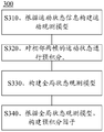
- a method for constructing a pre-integration factor in the embodiment of the present application is shown in FIG. 3.
- FIG. 3 is a schematic flowchart of a data processing method 300 according to an embodiment of the present application.
- the method 300 may be used to process the motion state information and construct a pre-integration factor.
- the method 300 in FIG. 3 may be executed by the front end 110 of the SLAM system in FIG. 1.
- the method 300 includes:
- an implementation manner of constructing a state observation model of the IMU according to the motion state information collected by the IMU is: constructing a state observation model of the IMU according to formulas (8) and (9).
- G g represents the gravity acceleration in global coordinates G
- ⁇ m represents the measured angular velocity
- ⁇ m represents the measured linear acceleration
- ⁇ represents the angular velocity
- ⁇ represents the linear acceleration
- b ⁇ represents the offset error of the angular velocity
- b a represents the linear acceleration.
- Offset error n ⁇ represents the noise of angular velocity
- n a represents the noise of linear acceleration.
- the motion state of 3D points of two adjacent frames may be pre-integrated according to the state observation model of the IMU.
- integration can be performed according to formulas (10) and (11).
- a global state observation model is constructed according to the pre-integration result in S420.
- a global state observation model in a global coordinate system can be constructed according to formulas (12), (13), and (14).
- G g represents the acceleration of gravity at global coordinates G
- G Represents the position in the global coordinate system G
- G Represents the velocity in the global coordinate system G
- ⁇ T represents the time difference between two adjacent frames
- k ⁇ k + 1 represents the pre-integration of relative speed and displacement
- k ⁇ k + 1 is the pre-integration of rotation.
- a pre-integration factor can be constructed according to formula (15).
- r I (x) represents the residual of the global state observation model constructed based on the IMU pre-integration
- G v I represents the speed in the global coordinate system
- G p I represents the position in the global coordinate system G
- G g represents the acceleration of gravity in the global coordinate G
- k ⁇ k + 1 represents pre-integration of relative speed and displacement
- k ⁇ k + 1 represents pre-integration of rotation
- b g represents offset error of gyroscope
- b a represents accelerometer Offset error
- ⁇ T represents the time difference between two adjacent frames
- ⁇ b a represents the difference between the offset errors of the linear acceleration of the adjacent two frames
- ⁇ b w represents the difference between the offset errors of the angular velocity of the two adjacent frames.
- an objective function may be constructed according to the surface feature factor and the pre-integration factor.
- Constructing an objective function according to the area feature factor and the pre-integration factor may include: constructing a state variable according to the area feature factor and the pre-integration factor, and constructing an objective function according to the state variable x.
- a state variable can be constructed according to formula (16).
- x ⁇ represents a surface characteristic state, which can be expressed by formula (17)
- x I represents an IMU state, and can be expressed by formula (18).
- Equation (18) Represents the rotation transformation of the global coordinate system G to the IMU coordinate system I
- G v I represents the speed of the IMU in the global coordinate system
- G p I represents the position of the IMU in the global coordinate system
- b g represents the offset error of the gyroscope
- b a Represents the offset error of the accelerometer.
- an objective function can be constructed according to formula (19).
- r Pi (x) is shown in formula (7)
- r Ij (x) is shown in formula (15).
- the fusion of the surface feature factor and the pre-integration factor can improve the pose and the accuracy of the map output by the SLAM method.
- the pose estimation may be performed according to the objective function, and the pose of the smart device may be output.
- a factor map may be constructed according to the objective function, and the pose estimation may be solved through the factor map.
- S260 may be performed by the backend 120 of the SLAM system in FIG. 1.
- the map construction can be completed according to the pose estimation, and the pose and the map can be output at the same time.
- FIG. 4 is a schematic block diagram of a data processing apparatus according to an embodiment of the present application. It should be understood that the apparatus 400 for processing data shown in FIG. 4 is merely an example, and the apparatus in the embodiment of the present application may further include other modules or units.
- the device 400 may include an acquisition module 410, a first determination module 420, a calculation module 430, a second determination module 440, a positioning module 450, and a map construction module 460.
- Each module included in the apparatus 400 may be implemented by software and / or hardware.
- the acquisition module 410 may be a receiver
- the first determination module 420, the calculation module 430, the second determination module 440, the positioning module 450, and the map construction module 460 may be processors.
- the acquisition module 410 may be a communication interface
- a first determination module 420, a calculation module 430, a second determination module 440, a positioning module 450, and a map construction module 460 may be a processor.
- the device 400 may be a chip.
- the first determination module 420 and the second determination module 440 may be the same module.
- the positioning module 450 and the map construction module 460 may be the same module.
- the apparatus 400 may further include a memory for storing program code executed by the processor, and may even be used for storing data.
- the apparatus 400 may be configured to perform steps in the method described in any one of FIG. 2 or FIG. 3.
- the obtaining module 410 is configured to obtain data of each 3D point in the first 3D point set, and the data of each 3D point in the first 3D point set is collected by the smart device when it is in the first position.
- the first 3D point set includes a plurality of 3D points located in a first coordinate system;
- a first determining module 420 is configured to determine a first sub 3D point set from the first 3D point set, the first sub 3D point set forms a first plane, and the first plane is the first coordinate system Any plane inside
- a calculation module 430 is configured to calculate a plurality of first distances, where the first distance is a distance between a first 3D point and the first position, and the first distance corresponds to the first 3D point in a one-to-one manner, The first 3D point is any 3D point in the first sub 3D point set;
- a second determining module 440 according to the plurality of first distances, determining a first target 3D point from the first sub 3D point set;
- a positioning module 450 is configured to use the first target 3D point as a constraint to locate the smart device and obtain a pose of the first position.
- the apparatus further includes:
- a map construction module 460 is configured to perform a map construction on the area passed by the smart device by using the first target 3D point as a constraint.
- the first target 3D point is a 3D point with a minimum distance from the first position in the first sub 3D point set.
- the first position is an origin of the first coordinate system
- the first distance is between a 3D point corresponding to the first distance and an origin of the first coordinate system. the distance.
- the obtaining module 410 is further configured to obtain data of each 3D point in a second 3D point set, and data of each 3D point in the second 3D point set is the smart Acquired when the device is in the second position, the second 3D point set includes a plurality of 3D points located in a second coordinate system;
- the first determining module 420 is further configured to determine a second sub 3D point set from the second 3D point set, the second sub 3D point set forms a second plane, and the second plane is the first plane. Any plane in the two coordinate system;
- the calculation module 430 is further configured to calculate a plurality of second distances, where the second distance is a distance between a second 3D point and the second position, and the second distance is one of the second 3D point.
- the second 3D point is any 3D point in the second sub 3D point set;
- the second determining module 440 is further configured to determine a second target 3D point from the second sub 3D point set according to the multiple second distances;
- the positioning module 450 is specifically configured to:
- a first position is a starting point
- the first vector is an end point of the first target three-dimensional point
- the first vector is used to determine a first plane in the first coordinate system
- the second vector is based on the A second position is a starting point
- the second vector is an end point of the second target three-dimensional point
- the second vector is used to determine a second plane in the second coordinate system.
- the second target 3D point is a 3D point with a smallest distance between the second sub 3D point set and the second position.
- the second position is an origin of the second coordinate system
- the second distance is between a 3D point corresponding to the second distance and an origin of the second coordinate system. the distance.
- the positioning module 450 is specifically configured to: determine a projection of the second vector in the first coordinate system, and determine whether the first vector and the second vector are in all positions. When a distance between projections in the first coordinate system is less than or equal to a preset distance, using a residual between the projection of the first vector and the second vector in the first coordinate system as a constraint condition .
- the positioning module 450 is specifically configured to determine a projection of the first vector in the second coordinate system, and determine that the first vector is in the second coordinate system.
- the distance between the projection of and the second vector is less than or equal to a preset distance
- the constraint between the projection of the first vector in the second coordinate system and the second vector is used as a constraint .
- the positioning module 450 is specifically configured to obtain motion state information collected by an inertial measurement unit, where the motion state information includes the smart device acquiring the first three-dimensional data at the first position. Motion state information at the time of point data and motion state information when the smart device collects data of the second three-dimensional point at the second position;
- the disclosed systems, devices, and methods may be implemented in other ways.
- the device embodiments described above are only schematic.
- the division of the unit is only a logical function division.
- multiple units or components may be combined or Can be integrated into another system, or some features can be ignored or not implemented.
- the displayed or discussed mutual coupling or direct coupling or communication connection may be indirect coupling or communication connection through some interfaces, devices or units, which may be electrical, mechanical or other forms.
- the units described as separate components may or may not be physically separated, and the components displayed as units may or may not be physical units, may be located in one place, or may be distributed on multiple network units. Some or all of the units may be selected according to actual needs to achieve the objective of the solution of this embodiment.
- each functional unit in each embodiment of the present application may be integrated into one processing unit, or each of the units may exist separately physically, or two or more units may be integrated into one unit.
- processors in the embodiment of the present application may be a central processing unit (CPU), and the processor may also be other general-purpose processors, digital signal processors (DSPs), and application-specific integrated circuits. (application specific integrated circuit (ASIC)), field programmable gate array (field programmable gate array, FPGA) or other programmable logic devices, discrete gate or transistor logic devices, discrete hardware components, etc.
- a general-purpose processor may be a microprocessor or the processor may be any conventional processor or the like.
- the functions are implemented in the form of software functional units and sold or used as independent products, they can be stored in a computer-readable storage medium.
- the technical solution of this application is essentially a part that contributes to the existing technology or a part of the technical solution can be embodied in the form of a software product.
- the computer software product is stored in a storage medium, including Several instructions are used to cause a computer device (which may be a personal computer, a server, or a network device, etc.) to perform all or part of the steps of the method described in the embodiments of the present application.
- the aforementioned storage media include: U disks, mobile hard disks, read-only memories (ROMs), random access memories (RAMs), magnetic disks or compact discs and other media that can store program codes .
Abstract
A data processing method comprises: acquiring data of each three-dimensional point in a first three-dimensional point set (S210), the data of each three-dimensional point in the first three-dimensional point set being acquired by a smart device when being at a first position, the first three-dimensional point set including a plurality of three-dimensional points located in a first coordinate system; determining, from the first three-dimensional point set, a first sub three-dimensional point set (S220), the first sub three-dimensional point set forming a first plane; calculating a plurality of first distances (S230), a first distance being the distance between a first three-dimensional point and the first position, the first three-dimensional point being any one three-dimensional point in the first sub three-dimensional point set; according to the plurality of first distances, determining, from the first sub three-dimensional point set, a first target three-dimensional point (S240); and using the first target three-dimensional point as a constraint condition, to locate the smart device, and acquire the pose thereof at the first position (S250). The method reduces the overheads of computing resources and computing time, improving the running efficiency of the whole SLAM process.
Description
本申请要求于2018年09月30日提交中国专利局、申请号为201811156022.1、申请名称为“一种处理数据的方法和装置”的中国专利申请的优先权,其全部内容通过引用结合在本申请中。This application claims the priority of a Chinese patent application filed on September 30, 2018 with the Chinese Patent Office, application number 201811156022.1, and application name "A Method and Device for Processing Data", the entire contents of which are incorporated herein by reference. in.
本申请涉及人工智能领域,并且更具体地,涉及一种处理数据的方法和装置。The present application relates to the field of artificial intelligence, and more particularly, to a method and device for processing data.
同时定位与地图构建(simultaneous localization and mapping,SLAM)技术是机器人能够探索未知环境所依赖的关键能力。机器人在没有环境先验信息的情况下,利用自身搭载的传感器(摄像头、激光等)对周围环境的特征进行观测,并构建基于相关观测约束的优化目标,进而通过对优化目标的求解完成系统状态向量,即环境特征位置与机器人位姿的估计,同时完成地图构建与自定位。Simultaneous localization and mapping (SLAM) technology is a key capability on which robots can explore unknown environments. In the absence of prior information about the environment, the robot observes the characteristics of the surrounding environment by using its own sensors (camera, laser, etc.), and constructs optimization goals based on relevant observation constraints, and then completes the system state by solving the optimization goals. Vector, which is the estimation of the environment feature position and robot pose, and completes the map construction and self-localization.
在当前SLAM技术领域,主要使用激光雷达和/或摄像头对周围环境的路标进行观测。在基于激光雷达的SLAM中,一种机器人运动姿态估计的方法为:依据惯性测量单元(inertial measurement unit,IMU)对IMU和激光雷达采集的点云数据进行注册,从注册好的每一帧点云数据中提取所有的线特征点和所有的面特征点;然后将当前帧中所有的线特征点和所有的面特征点依据上一次估计出的位姿变换投影到前一帧的坐标系下,并匹配各自距离最近的点;再根据上述线特征点到对应线的距离和上述面特征点到对应面的距离建立约束,并通过列文伯格(Levenberg-Marquardt,LM)算法迭代优化,求解最优的运动位姿。该方法中,需要对大量的特征点构建的约束迭代优化求解,运算量较大,浪费计算资源和时间开销。In the current SLAM technology field, lidars and / or cameras are mainly used to observe the landmarks of the surrounding environment. In LIAM-based SLAM, a method for robot motion and attitude estimation is: registering point cloud data collected by IMU and lidar based on inertial measurement unit (IMU), and registering each frame point Extract all line feature points and all surface feature points from the cloud data; then project all line feature points and all surface feature points in the current frame to the coordinate system of the previous frame according to the pose estimate last estimated , And match the points closest to each other; then establish constraints based on the distance from the line feature point to the corresponding line and the distance from the surface feature point to the corresponding surface, and iteratively optimize through the Levenberg-Marquardt (LM) algorithm, Find the optimal motion pose. In this method, it is necessary to solve the constraints iteratively for a large number of feature points, which requires a large amount of calculation and wastes computing resources and time.
因此,如何降低SLAM运动姿态估计过程中的计算资源和计算时间开销,提升整个SLAM过程的运行效率成为了一个亟待解决的问题。Therefore, how to reduce the calculation resources and calculation time overhead in the SLAM motion pose estimation process and improve the operation efficiency of the entire SLAM process has become an urgent problem.
发明内容Summary of the Invention
本申请提供一种处理数据的方法和装置,能够降低计算资源及计算时间的开销,提升整个SLAM过程的运行效率。The present application provides a method and device for processing data, which can reduce the cost of computing resources and computing time, and improve the operating efficiency of the entire SLAM process.
第一方面,本申请提供一种处理数据的方法,该方法包括:获取第一三维点集合中每个三维点的数据,所述每个三维点的数据是智能设备在第一位置时采集得到的,所述第一三维点集合包括位于第一坐标系的多个三维点;从所述第一三维点集合中确定第一子三维点集合,所述第一子三维点集合形成第一平面,所述第一平面为所述第一坐标系内的任意一个平面;计算多个第一距离,所述第一距离为第一三维点与所述第一位置之间的距离,所述第一距离与所述第一三维点一一对应,所述第一三维点是所述第一子三维点集合中的 任意一个三维点;根据所述多个第一距离,从所述第一子三维点集合中确定第一目标三维点;将所述第一目标三维点作为约束条件,对所述智能设备进行定位,获取所述第一位置的位姿。In a first aspect, the present application provides a method for processing data. The method includes: acquiring data of each three-dimensional point in a first three-dimensional point set, where the data of each three-dimensional point is acquired when the smart device is in a first position. The first three-dimensional point set includes a plurality of three-dimensional points located in a first coordinate system. A first sub-three-dimensional point set is determined from the first three-dimensional point set, and the first sub-three-dimensional point set forms a first plane. The first plane is any plane in the first coordinate system; a plurality of first distances are calculated, and the first distance is a distance between a first three-dimensional point and the first position, and the first A distance corresponds one-to-one to the first three-dimensional point, and the first three-dimensional point is any one three-dimensional point in the first sub-three-dimensional point set; according to the plurality of first distances, from the first sub-point A first target three-dimensional point is determined from the three-dimensional point set; using the first target three-dimensional point as a constraint condition, positioning the smart device to obtain the pose of the first position.
根据本申请实施例中的方法,从所述第一子三维点集合中确定第一目标三维点,第一子三维点集合中包括多个三维点,将第一子三维点集合中的第一目标三维点作为约束条件,可以降低后续步骤的计算量及计算时间的开销,提升整个SLAM过程的运行效率。According to the method in the embodiment of the present application, a first target three-dimensional point is determined from the first sub-three-dimensional point set, and the first sub-three-dimensional point set includes a plurality of three-dimensional points. The target three-dimensional point is used as a constraint condition, which can reduce the calculation amount and time of the subsequent steps and improve the operating efficiency of the entire SLAM process.
在一种可能的实现方式中,所述将所述第一目标三维点作为约束条件,对所述智能设备进行定位,包括:根据所述第一目标三维点确定约束条件,所述约束条件用于影响所述智能设备的定位过程。In a possible implementation manner, the positioning the smart device by using the first target three-dimensional point as a constraint condition includes determining a constraint condition according to the first target three-dimensional point, where the constraint condition is used To affect the positioning process of the smart device.
在一种可能的实现方式中,所述方法还包括:将所述第一目标三维点作为约束条件对所述智能设备途经区域进行地图构建。In a possible implementation manner, the method further includes: using the first three-dimensional point of the target as a constraint condition to construct a map of the area passed by the smart device.
在一种可能的实现方式中,所述第一目标三维点是所述第一子三维点集合中与所述第一位置之间的距离最小的三维点。In a possible implementation manner, the first target three-dimensional point is a three-dimensional point with a minimum distance from the first position in the first sub-three-dimensional point set.
根据本申请实施例中的方法,第一目标三维点是与第一坐标系的原点之间的距离最小的三维点,即与第一坐标系的原点距离最近的点,便于后续以第一目标三维点作为参数表示第一平面的面特征。According to the method in the embodiment of the present application, the first target three-dimensional point is a three-dimensional point having the smallest distance from the origin of the first coordinate system, that is, a point closest to the origin of the first coordinate system, which is convenient for subsequent use of the first target Three-dimensional points are used as parameters to represent surface features of the first plane.
在一种可能的实现方式中,所述第一位置为所述第一坐标系的原点,所述第一距离为所述第一距离对应的三维点与所述第一坐标系的原点之间的距离。In a possible implementation manner, the first position is an origin of the first coordinate system, and the first distance is between a three-dimensional point corresponding to the first distance and an origin of the first coordinate system. the distance.
根据本申请实施例中的方法,第一坐标系为以第一位置为原点的相对坐标系,所述第一平面位于第一坐标系中,能够消除第一平面的面特征的奇异性,从而可以提高SLAM方法的鲁棒性。According to the method in the embodiment of the present application, the first coordinate system is a relative coordinate system with the first position as an origin, and the first plane is located in the first coordinate system, which can eliminate the singularity of the surface features of the first plane, thereby Can improve the robustness of the SLAM method.
在一种可能的实现方式中,所述方法还包括:获取第二三维点集合中每个三维点的数据,所述第二三维点集合中每个三维点的数据是所述智能设备在第二位置时采集得到的,所述第二三维点集合包括位于第二坐标系的多个三维点;从所述第二三维点集合中确定第二子三维点集合,所述第二子三维点集合形成第二平面,所述第二平面为所述第二坐标系内的任意一个平面;计算多个第二距离,所述第二距离为第二三维点与所述第二位置之间的距离,所述第二距离与所述第二三维点一一对应,所述第二三维点是所述第二子三维点集合中的任意一个三维点;根据所述多个第二距离,从所述第二子三维点集合中确定第二目标三维点。In a possible implementation manner, the method further includes: obtaining data of each three-dimensional point in the second three-dimensional point set, where the data of each three-dimensional point in the second three-dimensional point set is The second three-dimensional point set is obtained by collecting at two positions, and the second three-dimensional point set includes a plurality of three-dimensional points located in a second coordinate system. Set to form a second plane, the second plane being any plane in the second coordinate system; calculating a plurality of second distances, the second distances being between a second three-dimensional point and the second position Distance, the second distance corresponds one-to-one to the second three-dimensional point, and the second three-dimensional point is any one of the three-dimensional points in the second sub-three-dimensional point set; according to the plurality of second distances, from A second target three-dimensional point is determined in the second sub-three-dimensional point set.
在一种可能的实现方式中,所述将所述第一目标三维点作为约束条件,对所述智能设备进行定位,包括:将第一向量与第二向量之间的残差作为约束条件,对所述智能设备进行定位,其中,所述残差包括所述第一向量与所述第二向量之间的距离,所述第一向量以所述第一位置为起点,所述第一向量以所述第一目标三维点为终点,所述第一向量用于在所述第一坐标系中确定所述第一平面,所述第二向量以所述第二位置为起点,所述第二向量以所述第二目标三维点为终点,所述第二向量用于在所述第二坐标系中确定所述第二平面。In a possible implementation manner, the positioning the smart device by using the first target three-dimensional point as a constraint condition includes: using a residual between a first vector and a second vector as a constraint condition, Positioning the smart device, wherein the residual includes a distance between the first vector and the second vector, the first vector uses the first position as a starting point, and the first vector With the first target three-dimensional point as an end point, the first vector is used to determine the first plane in the first coordinate system, the second vector uses the second position as a starting point, and the first A second vector ends with the second target three-dimensional point, and the second vector is used to determine the second plane in the second coordinate system.
在一种可能的实现方式中,所述第二目标三维点是所述第二子三维点集合中与所述第二位置之间的距离最小的三维点。In a possible implementation manner, the second target three-dimensional point is a three-dimensional point with the smallest distance between the second sub-three-dimensional point set and the second position.
在一种可能的实现方式中,所述第二位置为所述第二坐标系的原点,所述第二距离为 所述第二距离对应的三维点与所述第二坐标系的原点之间的距离。In a possible implementation manner, the second position is an origin of the second coordinate system, and the second distance is between a three-dimensional point corresponding to the second distance and an origin of the second coordinate system. the distance.
在一种可能的实现方式中,在所述将第一向量与第二向量之间的残差作为约束条件之前,所述方法还包括:确定所述第二向量在所述第一坐标系中的投影,并在所述第一向量与所述第二向量在所述第一坐标系中的投影之间的距离小于或等于预设距离时,将所述第一向量和所述第二向量在所述第一坐标系中的投影之间的残差作为约束条件。In a possible implementation manner, before the taking the residual between the first vector and the second vector as a constraint condition, the method further includes: determining that the second vector is in the first coordinate system When the distance between the projection of the first vector and the projection of the second vector in the first coordinate system is less than or equal to a preset distance, dividing the first vector and the second vector Residuals between projections in the first coordinate system are used as constraints.
在一种可能的实现方式中,在所述将第一向量与第二向量之间的残差作为约束条件之前,所述方法还包括:确定所述第一向量在所述第二坐标系中的投影,并在所述第一向量在所述第二坐标系中的投影与所述第二向量之间的距离小于或等于预设距离时,将所述第一向量在所述第二坐标系中的投影和所述第二向量之间的残差作为约束条件。In a possible implementation manner, before the using a residual between a first vector and a second vector as a constraint condition, the method further includes: determining that the first vector is in the second coordinate system When the distance between the projection of the first vector in the second coordinate system and the second vector is less than or equal to a preset distance, placing the first vector at the second coordinate The residual between the projection in the system and the second vector is used as a constraint.
根据本申请实施例中的方法,将第一向量和第二向量投影到同一相对坐标系中,能够计算第一向量和第二向量的残差,从而可以提高SLAM方法的鲁棒性。According to the method in the embodiment of the present application, by projecting the first vector and the second vector into the same relative coordinate system, the residuals of the first vector and the second vector can be calculated, thereby improving the robustness of the SLAM method.
在一种可能的实现方式中,所述将第一向量与第二向量之间的残差作为约束条件,对所述智能设备进行定位,包括:获取惯性测量单元采集的运动状态信息,所述运动状态信息包括所述智能设备在所述第一位置采集所述第一三维点的数据时的运动状态信息与所述智能设备在所述第二位置采集所述第二三维点的数据时的运动状态信息;将所述运动状态信息和所述第一向量与所述第二向量之间的残差作为约束条件,对所述智能设备进行定位。In a possible implementation manner, using the residual between the first vector and the second vector as a constraint condition to locate the smart device includes: acquiring motion state information collected by an inertial measurement unit, where The movement state information includes movement state information when the smart device collects data of the first three-dimensional point at the first position and when the smart device collects data of the second three-dimensional point at the second position. Motion state information; using the motion state information and a residual between the first vector and the second vector as constraints to locate the smart device.
根据本申请实施例中的方法,将所述运动状态信息和所述第一向量与所述第二向量之间的残差作为约束条件,对所述智能设备进行定位,融合了面特征因子和预积分因子,可以提高SLAM系统的精度。According to the method in the embodiment of the present application, the motion state information and the residual between the first vector and the second vector are used as constraint conditions to locate the smart device, and a surface feature factor and The pre-integration factor can improve the accuracy of the SLAM system.
第二方面,本申请提供了一种处理数据的装置,该装置包括:获取模块,用于获取第一三维点集合中每个三维点的数据,所述每个三维点的数据是智能设备在第一位置时采集得到的,所述第一三维点集合包括位于第一坐标系的多个三维点;第一确定模块,用于从所述第一三维点集合中确定第一子三维点集合,所述第一子三维点集合形成第一平面,所述第一平面为所述第一坐标系内的任意一个平面;计算模块,用于计算多个第一距离,所述第一距离为第一三维点与所述第一位置之间的距离,所述第一距离与所述第一三维点一一对应,所述第一三维点是所述第一子三维点集合中的任意一个三维点;第二确定模块,根据所述多个第一距离,从所述第一子三维点集合中确定第一目标三维点;定位模块,用于将所述第一目标三维点作为约束条件,对所述智能设备进行定位,获取所述第一位置的位姿。In a second aspect, the present application provides a device for processing data. The device includes: an acquiring module, configured to acquire data of each three-dimensional point in the first three-dimensional point set, where the data of each three-dimensional point is a smart device. Acquired at the first position, the first three-dimensional point set includes a plurality of three-dimensional points located in a first coordinate system; a first determining module, configured to determine a first sub three-dimensional point set from the first three-dimensional point set , The first sub three-dimensional point set forms a first plane, and the first plane is any plane in the first coordinate system; a calculation module is configured to calculate a plurality of first distances, and the first distance is A distance between a first three-dimensional point and the first position, the first distance corresponding to the first three-dimensional point, the first three-dimensional point is any one of the first sub-three-dimensional point set A three-dimensional point; a second determination module that determines a first target three-dimensional point from the first set of three-dimensional points according to the plurality of first distances; a positioning module that is configured to use the first target three-dimensional point as a constraint For the smart Preparation locate, acquire the position and orientation of the first position.
根据本申请实施例中的装置,从所述第一子三维点集合中确定第一目标三维点,第一子三维点集合中包括多个三维点,将第一子三维点集合中的第一目标三维点作为约束条件,可以降低后续步骤的计算量及计算时间的开销,提升整个SLAM过程的运行效率。According to the device in the embodiment of the present application, a first target three-dimensional point is determined from the first sub-three-dimensional point set, the first sub-three-dimensional point set includes a plurality of three-dimensional points, and the first The target three-dimensional point is used as a constraint condition, which can reduce the calculation amount and time of the subsequent steps and improve the operating efficiency of the entire SLAM process.
在一种可能的实现方式中,所述定位模块还用于:根据所述第一目标三维点确定约束条件,所述约束条件用于影响所述智能设备的定位过程。In a possible implementation manner, the positioning module is further configured to determine a constraint condition according to the first target three-dimensional point, where the constraint condition is used to affect a positioning process of the smart device.
在一种可能的实现方式中,所述装置还包括:地图构建模块,用于将所述第一目标三维点作为约束条件对所述智能设备途经区域进行地图构建。In a possible implementation manner, the apparatus further includes: a map construction module, configured to use the first three-dimensional point of the target as a constraint condition to construct a map for the area passed by the smart device.
在一种可能的实现方式中,所述第一目标三维点是所述第一子三维点集合中与所述第一位置之间的距离最小的三维点。In a possible implementation manner, the first target three-dimensional point is a three-dimensional point with a minimum distance from the first position in the first sub-three-dimensional point set.
根据本申请实施例中的装置,第一目标三维点是与第一坐标系的原点之间的距离最小的三维点,即与第一坐标系的原点距离最近的点,便于后续以第一目标三维点作为参数表示第一平面的面特征。According to the device in the embodiment of the present application, the first target three-dimensional point is a three-dimensional point having the smallest distance from the origin of the first coordinate system, that is, a point closest to the origin of the first coordinate system, which is convenient for subsequent use of the first target. Three-dimensional points are used as parameters to represent surface features of the first plane.
在一种可能的实现方式中,所述第一位置为所述第一坐标系的原点,所述第一距离为所述第一距离对应的三维点与所述第一坐标系的原点之间的距离。In a possible implementation manner, the first position is an origin of the first coordinate system, and the first distance is between a three-dimensional point corresponding to the first distance and an origin of the first coordinate system. the distance.
根据本申请实施例中的装置,第一坐标系为以第一位置为原点的相对坐标系,所述第一平面位于第一坐标系中,能够消除第一平面的面特征的奇异性,从而可以提高SLAM方法的鲁棒性。According to the device in the embodiment of the present application, the first coordinate system is a relative coordinate system with the first position as an origin, and the first plane is located in the first coordinate system, which can eliminate the singularity of the surface features of the first plane, thereby Can improve the robustness of the SLAM method.
在一种可能的实现方式中,所述获取模块还用于:获取第二三维点集合中每个三维点的数据,所述第二三维点集合中每个三维点的数据是所述智能设备在第二位置时采集得到的,所述第二三维点集合包括位于第二坐标系的多个三维点;所述第一确定模块还用于:从所述第二三维点集合中确定第二子三维点集合,所述第二子三维点集合形成第二平面,所述第二平面为所述第二坐标系内的任意一个平面;所述计算模块还用于:计算多个第二距离,所述第二距离为第二三维点与所述第二位置之间的距离,所述第二距离与所述第二三维点一一对应,所述第二三维点是所述第二子三维点集合中的任意一个三维点;所述第二确定模块还用于:根据所述多个第二距离,从所述第二子三维点集合中确定第二目标三维点。In a possible implementation manner, the obtaining module is further configured to obtain data of each three-dimensional point in the second three-dimensional point set, and the data of each three-dimensional point in the second three-dimensional point set is the smart device. Collected at the second position, the second three-dimensional point set includes a plurality of three-dimensional points located in a second coordinate system; the first determining module is further configured to determine a second from the second three-dimensional point set. A sub-three-dimensional point set, the second sub-three-dimensional point set forming a second plane, and the second plane is any plane in the second coordinate system; the calculation module is further configured to calculate a plurality of second distances , The second distance is a distance between a second three-dimensional point and the second position, the second distance corresponds one-to-one to the second three-dimensional point, and the second three-dimensional point is the second child Any one of the three-dimensional point sets; the second determining module is further configured to determine a second target three-dimensional point from the second sub-three-dimensional point set according to the plurality of second distances.
在一种可能的实现方式中,所述定位模块具体用于:将第一向量与第二向量之间的残差作为约束条件,对所述智能设备进行定位,其中,所述残差包括第一向量与第二向量之间的距离,第一向量以所述第一位置为起点,所述第一向量以所述第一目标三维点为终点,所述第一向量用于在所述第一坐标系中确定所述第一平面,所述第二向量以所述第二位置为起点,所述第二向量以所述第二目标三维点为终点,所述第二向量用于在所述第二坐标系中确定所述第二平面。In a possible implementation manner, the positioning module is specifically configured to use the residual between the first vector and the second vector as a constraint to locate the smart device, where the residual includes a first A distance between a vector and a second vector, the first vector taking the first position as a starting point, the first vector taking the first target three-dimensional point as an end point, and the first vector used for The first plane is determined in a coordinate system, the second vector starts from the second position, the second vector ends with the second target three-dimensional point, and the second vector is used for The second plane is determined in the second coordinate system.
在一种可能的实现方式中,所述第二目标三维点是所述第二子三维点集合中与所述第二位置之间的距离最小的三维点。In a possible implementation manner, the second target three-dimensional point is a three-dimensional point with the smallest distance between the second sub-three-dimensional point set and the second position.
在一种可能的实现方式中,所述第二位置为所述第二坐标系的原点,所述第二距离为所述第二距离对应的三维点与所述第二坐标系的原点之间的距离。In a possible implementation manner, the second position is an origin of the second coordinate system, and the second distance is between a three-dimensional point corresponding to the second distance and an origin of the second coordinate system. the distance.
在一种可能的实现方式中,所述定位模块具体用于:确定所述第二向量在所述第一坐标系中的投影,并在所述第一向量与所述第二向量在所述第一坐标系中的投影之间的距离小于或等于预设距离时,将所述第一向量和所述第二向量在所述第一坐标系中的投影之间的残差作为约束条件。In a possible implementation manner, the positioning module is specifically configured to determine a projection of the second vector in the first coordinate system, and determine whether the first vector and the second vector are in the first coordinate system. When a distance between projections in the first coordinate system is less than or equal to a preset distance, a residual between the projections of the first vector and the second vector in the first coordinate system is used as a constraint condition.
在一种可能的实现方式中,所述定位模块具体用于:确定所述第一向量在所述第二坐标系中的投影,并在所述第一向量在所述第二坐标系中的投影与所述第二向量之间的距离小于或等于预设距离时,将所述第一向量在所述第二坐标系中的投影和所述第二向量之间的残差作为约束条件。In a possible implementation manner, the positioning module is specifically configured to determine a projection of the first vector in the second coordinate system, and determine a projection of the first vector in the second coordinate system. When a distance between the projection and the second vector is less than or equal to a preset distance, a constraint between the projection of the first vector in the second coordinate system and the second vector is used as a constraint.
根据本申请实施例中的装置,将第一向量和第二向量投影到同一相对坐标系中,能够计算第一向量和第二向量的残差,从而可以提高SLAM方法的鲁棒性。According to the device in the embodiment of the present application, the first vector and the second vector are projected into the same relative coordinate system, and the residuals of the first vector and the second vector can be calculated, thereby improving the robustness of the SLAM method.
在一种可能的实现方式中,所述定位模块具体用于:获取惯性测量单元采集的运动状态信息,所述运动状态信息包括所述智能设备在所述第一位置采集所述第一三维点的数据 时的运动状态信息与所述智能设备在所述第二位置采集所述第二三维点的数据时的运动状态信息;将所述运动状态信息和所述第一向量与所述第二向量之间的残差作为约束条件,对所述智能设备进行定位。In a possible implementation manner, the positioning module is specifically configured to obtain motion state information collected by the inertial measurement unit, where the motion state information includes the smart device acquiring the first three-dimensional point at the first position. The motion state information at the time of the data and the motion state information when the smart device collects the data of the second three-dimensional point at the second position; combining the motion state information and the first vector with the second Residuals between vectors are used as constraints to locate the smart device.
根据本申请实施例中的装置,将所述运动状态信息和所述第一向量与所述第二向量之间的残差作为约束条件,对所述智能设备进行定位,由于融合了面特征因子和预积分因子,可以提高SLAM系统的精度。According to the apparatus in the embodiment of the present application, the motion state information and the residual between the first vector and the second vector are used as constraint conditions to locate the smart device, because a surface feature factor is fused And pre-integration factors can improve the accuracy of the SLAM system.
第二方面中的装置包括的各个模块可以通过软件和/或硬件方式实现。Each module included in the apparatus in the second aspect may be implemented by software and / or hardware.
例如,第二方面中的装置包括的各个模块可以通过处理器实现,即第二方面中的装置可以包括处理器,该处理器用于执行程序指令,以实现该装置包括的各个模块能够实现的各个功能。For example, each module included in the device in the second aspect may be implemented by a processor, that is, the device in the second aspect may include a processor, and the processor is configured to execute program instructions to implement each of the various modules that the device includes. Features.
可选地,第二方面中的装置开可以包括存储器,用于存储处理器执行的程序指令,甚至用于存储各种数据。Optionally, the device in the second aspect may include a memory for storing program instructions executed by the processor, and even for storing various data.
可选地,第二方面中的装置可以是智能设备,例如智能机器人、无人机等。其中,该装置还可以包括接收器或发送器。Optionally, the device in the second aspect may be a smart device, such as a smart robot, a drone, or the like. The device may further include a receiver or a transmitter.
可选地,第二方面中的装置可以是能够集成在智能设备中的芯片,此时,该装置还可以包括通信接口。Optionally, the device in the second aspect may be a chip capable of being integrated in a smart device. At this time, the device may further include a communication interface.
第三方面,本申请提供了一种计算机可读存储介质。该计算机可读存储介质中存储用于处理数据的装置执行的程序代码。该程序代码包括用于执行第一方面或其中任意一种可能的实现方式中的方法的指令。In a third aspect, the present application provides a computer-readable storage medium. The computer-readable storage medium stores program code executed by a device for processing data. The program code includes instructions for executing the method in the first aspect or any one of the possible implementation manners.
第四方面,本申请提供了一种包含指令的计算机程序产品。当该计算机程序产品在处理数据的装置上运行时,使得该装置执行第一方面或其中任意一种可能的实现方式中的方法。In a fourth aspect, the present application provides a computer program product containing instructions. When the computer program product runs on a device that processes data, the device is caused to execute the method in the first aspect or any one of the possible implementation manners.
根据本申请实施例中的方法,从所述第一子三维点集合中确定第一目标三维点,第一子三维点集合中包括多个三维点,将第一子三维点集合中的第一目标三维点作为约束条件,可以降低后续步骤的计算量及计算时间的开销,提升整个SLAM过程的运行效率。According to the method in the embodiment of the present application, a first target three-dimensional point is determined from the first sub-three-dimensional point set, and the first sub-three-dimensional point set includes a plurality of three-dimensional points. The target three-dimensional point is used as a constraint condition, which can reduce the calculation amount and time of the subsequent steps and improve the operating efficiency of the entire SLAM process.
图1是本申请实施例的技术方案的一种应用场景的示意图。FIG. 1 is a schematic diagram of an application scenario of the technical solution of the embodiment of the present application.
图2是本申请一个实施例的处理数据的方法的示意性流程图。FIG. 2 is a schematic flowchart of a data processing method according to an embodiment of the present application.
图3是本申请另一个实施例的处理数据的方法的示意性流程图。FIG. 3 is a schematic flowchart of a data processing method according to another embodiment of the present application.
图4是本申请一个实施例的处理数据的装置的示意性框图。FIG. 4 is a schematic block diagram of a data processing apparatus according to an embodiment of the present application.
下面将结合附图,对本申请中的技术方案进行描述。The technical solutions in this application will be described below with reference to the drawings.
本申请实施例适用于同时定位与地图构建(simultaneous localization and mapping,SLAM)领域以及任何用于非线性估计问题中的状态边缘化处理的智能设备(intelligent equipment)中。The embodiments of the present application are applicable to the field of simultaneous localization and map construction (SLultaneous Localization and Mapping, SLAM), and any intelligent equipment used for state marginalization in a nonlinear estimation problem.
应理解,智能设备是指任何一种具有计算处理能力的设备、器械或者机器,本申请实施例中的智能设备可以是机器人(robot)、自动驾驶汽车(autonomous vehicles)、无人 机(unmanned aerial vehicle)、智能家居(smart home)和手机终端等,本申请对该智能设备并不做任何限定。It should be understood that a smart device refers to any kind of device, instrument, or machine with computing processing capabilities. The smart devices in the embodiments of the present application may be robots, autonomous vehicles, and unmanned aerial vehicles. vehicles, smart homes, mobile phones, etc., this application does not place any restrictions on smart devices.
图1示出了本申请实施例的技术方案的一种应用场景的示意图,如图1所示,本申请实施例的技术方案适用于智能设备的SLAM系统100中,该SLAM系统包括前端(Front-end)110和后端(Back-end)120,其中,前端110主要完成传感器的数据采集和数据关联,而后端120主要功能是对前端产生的模型进行参数估计以及优化。下面以智能设备为例对本申请实施例的技术方案进行描述。FIG. 1 shows a schematic diagram of an application scenario of the technical solution of the embodiment of the present application. As shown in FIG. 1, the technical solution of the embodiment of the present application is applicable to a SLAM system 100 of a smart device. The SLAM system includes a front end (Front -end) 110 and Back-end 120. Among them, the front-end 110 mainly completes sensor data collection and data association, and the main function of the back-end 120 is to estimate and optimize the parameters generated by the front-end model. The technical solution of the embodiment of the present application is described below by taking a smart device as an example.
本申请实施例以将IMU和激光雷达传感器作为观测输入传感器的智能设备为例。其中,IMU采集智能设备的运动状态信息,例如,运动状态信息可以包括SLAM装置的角速度和线加速度;激光雷达采集智能设备周围环境的三维(three dimensions,3D)点云(下文简称“3D点云”),该3D点云包括该智能设备周围环境中的多个三维点(下文也称“3D点”),所述三维点可以理解为具有三维坐标值的点。This embodiment of the present application takes as an example a smart device that uses an IMU and a lidar sensor as observation input sensors. Among them, the IMU collects the motion state information of the smart device. For example, the motion state information may include the angular velocity and linear acceleration of the SLAM device; the lidar acquires three-dimensional (3D) point clouds (hereinafter referred to as "3D point clouds") around the smart device. "), The 3D point cloud includes a plurality of three-dimensional points (hereinafter also referred to as" 3D points ") in the surroundings of the smart device, and the three-dimensional points can be understood as points having three-dimensional coordinate values.
可选地,可以使用三维坐标系来表示3D点的三维坐标值。Alternatively, a three-dimensional coordinate system may be used to represent three-dimensional coordinate values of a 3D point.
例如,可以用空间直角坐标系中的(x,y,z)三轴坐标位置表示3D点的三维坐标值,其中,x代表横轴坐标,y代表纵轴坐标,z代表竖轴坐标。For example, the (x, y, z) three-axis coordinate position in the spatial rectangular coordinate system can be used to represent the three-dimensional coordinate value of the 3D point, where x represents the horizontal axis coordinate, y represents the vertical axis coordinate, and z represents the vertical axis coordinate.
图2为本申请一个实施例的处理数据的方法的示意性流程图。应理解,图2示出了该方法的步骤或操作,但这些步骤或操作仅是示例,本申请实施例还可以执行其他操作或者图2中的各个操作的变形,或者,并不是所有步骤都需要执行,或者,这些步骤可以按照其他顺序执行。FIG. 2 is a schematic flowchart of a data processing method according to an embodiment of the present application. It should be understood that FIG. 2 shows the steps or operations of the method, but these steps or operations are merely examples. The embodiments of the present application may also perform other operations or variations of each operation in FIG. 2, or not all steps Need to be performed, or these steps can be performed in another order.
图2中的方法可以由图1中的SLAM系统100执行,该方法包括:The method in FIG. 2 may be executed by the SLAM system 100 in FIG. 1, and the method includes:
S210、获取第一3D点集合中每个3D点的数据,所述每个3D点的数据是智能设备在第一位置时采集得到的,所述第一3D点集合包括位于第一坐标系的多个3D点。S210. Acquire data of each 3D point in the first 3D point set, where the data of each 3D point is acquired by the smart device at the first position, and the first 3D point set includes data in a first coordinate system. Multiple 3D points.
可选地,S210可以由图1中的SLAM系统的前端110执行。Optionally, S210 may be performed by the front end 110 of the SLAM system in FIG. 1.
获取智能设备中的激光雷达传感器采集的当前帧的3D点云,其中,3D点云可以是包括多个3D点的3D点集合,因此,当前帧采集的3D点云也可以称为第一3D点集合。Obtain the 3D point cloud of the current frame collected by the lidar sensor in the smart device. The 3D point cloud may be a 3D point set including multiple 3D points. Therefore, the 3D point cloud collected in the current frame may also be called the first 3D. Point collection.
在本申请实施例中,智能设备位于第一位置时对周围环境进行观测,可以得到包括多个3D点的第一3D点集合。In the embodiment of the present application, when the smart device is located at the first position and observes the surrounding environment, a first 3D point set including multiple 3D points can be obtained.
可选地,上述第一位置可以是所述智能设备的中心点所处的位置,也可以是所述智能设备上的传感器的中心点所处的位置(这里的传感器可以是激光雷达或惯性测量单元),或者也可以是所述智能设备的着地点所处的位置,或者也可以是其他与所述智能设备之间的相对位置固定不变的点或位置,本申请实施例对此不作限定。Optionally, the first position may be a position where a center point of the smart device is located, or a position where a center point of a sensor on the smart device is located (the sensor here may be a lidar or an inertial measurement Unit), or may be the location where the smart device is located, or may be other points or locations where the relative position to the smart device is fixed, which is not limited in the embodiments of the present application .
在本申请实施例中,可以获取智能设备中的IMU采集的当前帧的运动状态信息。可选地,可以对采集到的第一3D点集合和运动状态信息进行时间同步。In the embodiment of the present application, the motion state information of the current frame collected by the IMU in the smart device can be obtained. Optionally, time synchronization may be performed on the collected first 3D point set and motion state information.
其中,时间同步也可以理解为,对第一3D点集合及运动状态信息进行时间对准,或者时间配准。The time synchronization can also be understood as time alignment or time registration of the first 3D point set and motion state information.
对采集到的第一3D点集合和运动状态信息进行时间同步,可以是指确定第一3D点集合及其对应的同一时刻的运动状态信息。应理解,这里的运动状态信息可以是指采集第一3D点集合时,该智能设备的运动状态信息。Performing time synchronization on the collected first 3D point set and motion state information may refer to determining the first 3D point set and the corresponding motion state information at the same time. It should be understood that the motion state information herein may refer to the motion state information of the smart device when the first 3D point set is collected.
在本申请实施例中,第一坐标系可以是绝对坐标系(绝对坐标系也可称为全局坐标系 或世界坐标系)。其中,绝对坐标系的坐标轴和原点的位置是固定不变,不随智能设备的移动而改变。In the embodiment of the present application, the first coordinate system may be an absolute coordinate system (the absolute coordinate system may also be referred to as a global coordinate system or a world coordinate system). Among them, the position of the coordinate axis and the origin of the absolute coordinate system is fixed and does not change with the movement of the smart device.
可选地,第一坐标系可以是相对坐标系。其中,相对坐标系的坐标轴和原点与智能设备的相对位置固定不变,不随智能设备的移动而改变。Alternatively, the first coordinate system may be a relative coordinate system. The relative position of the coordinate axis and the origin of the relative coordinate system with the smart device is fixed and does not change with the movement of the smart device.
可选地,当相对坐标系的原点是所述智能设备的中心点时,该相对坐标系也可称为局部坐标系。Optionally, when the origin of the relative coordinate system is the center point of the smart device, the relative coordinate system may also be referred to as a local coordinate system.
S220、从所述第一3D点集合中确定第一子3D点集合,所述第一子3D点集合形成第一平面,所述第一平面为所述第一坐标系内的任意一个平面。S220. Determine a first sub 3D point set from the first 3D point set, where the first sub 3D point set forms a first plane, and the first plane is any plane in the first coordinate system.
其中,第一3D点集合可以是激光雷达采集的当前帧的3D点云。The first 3D point set may be a 3D point cloud of the current frame collected by the lidar.
可选地,S220可以由图1中的SLAM系统的前端110执行。Optionally, S220 may be performed by the front end 110 of the SLAM system in FIG. 1.
在本申请实施例中,第一3D点集合可以划分为一个或多个3D点子集,同一个3D点子集中的多个3D点可以属于同一个平面,第一3D点集合划分得到的一个或多个3D子集可以称为第一子3D点集合。也可以说是,对所述第一3D点集合中包括的多个3D点进行平面分割。In the embodiment of the present application, the first 3D point set may be divided into one or more 3D point subsets, multiple 3D points in the same 3D point subset may belong to the same plane, and one or more of the first 3D point set is divided. The 3D subsets may be referred to as a first subset of 3D points. It can also be said that plane division is performed on a plurality of 3D points included in the first 3D point set.
例如,可以通过随机抽样一致(random sample consensus,RANSAC)算法对第一3D点集合中3D点的进行平面分割。For example, a 3D point in the first 3D point set can be planarly segmented by a random sampling consensus (RANSAC) algorithm.
可选地,第一子3D点集合可以包括多个3D点。其中,第一子3D点集合中的多个3D点可以位于同一平面。Optionally, the first sub 3D point set may include a plurality of 3D points. Among them, multiple 3D points in the first sub 3D point set may be located on the same plane.
可选地,第一子3D点集合中的多个3D点可以位于第一平面,所述第一平面可以是所述第一3D点集合中的多个3D点对应的多个平面中的一个平面。Optionally, multiple 3D points in the first sub 3D point set may be located on a first plane, and the first plane may be one of multiple planes corresponding to multiple 3D points in the first 3D point set flat.
也就是说,所述第一平面位于所述第一坐标系中。That is, the first plane is located in the first coordinate system.
作本申请实施例一种可能的实现方式,可以去除第一子3D点集合中的噪点。例如,可以通过Huber算法去除第一子3D点集合中的噪点。As a possible implementation manner of the embodiment of the present application, noise in the first sub 3D point set can be removed. For example, the noise in the first sub 3D point set can be removed by the Huber algorithm.
在本申请实施例中,去除第一子3D点集合中的噪点,可以降低去除平面分割产生的噪点影响,提升平面分割的鲁棒性。In the embodiment of the present application, removing the noise in the first sub 3D point set can reduce the influence of removing noise generated by the plane segmentation, and improve the robustness of the plane segmentation.
S230、计算多个第一距离,所述第一距离为第一3D点与所述第一位置之间的距离,所述第一距离与所述第一三维点一一对应,所述第一3D点是所述第一子3D点集合中的任意一个3D点。S230. Calculate a plurality of first distances, where the first distance is a distance between a first 3D point and the first position, the first distance corresponds to the first three-dimensional point, and the first The 3D point is any 3D point in the first sub 3D point set.
其中,所述多个第一距离可以与所述第一子3D点集合中的多个3D点一一对应,所述第一距离可以为所述第一距离对应的3D点与所述第一位置之间的距离。The plurality of first distances may correspond one-to-one to the plurality of 3D points in the first sub 3D point set, and the first distance may be a 3D point corresponding to the first distance and the first distance. The distance between the locations.
可选地,S230可以由图1中的SLAM系统的前端110执行。Optionally, S230 may be executed by the front end 110 of the SLAM system in FIG. 1.
在本申请实施例中,第一位置可以为第一坐标系的原点,因此,第一距离可以为第一距离对应的3D点与第一坐标系的原点之间的距离。In the embodiment of the present application, the first position may be an origin of the first coordinate system, and therefore, the first distance may be a distance between a 3D point corresponding to the first distance and an origin of the first coordinate system.
例如,第一坐标系可以是局部坐标系。此时,当前帧采集到的第一3D点集合中的多个3D点的坐标,可以是在局部坐标系中的坐标。应理解,局部坐标系属于相对坐标系中的一种。For example, the first coordinate system may be a local coordinate system. At this time, the coordinates of multiple 3D points in the first 3D point set collected in the current frame may be coordinates in a local coordinate system. It should be understood that the local coordinate system belongs to one of the relative coordinate systems.
在本申请实施例中,当第一坐标系为局部坐标系时,能够消除第一平面的面特征的奇异性,从而可以提高SLAM方法的鲁棒性。In the embodiment of the present application, when the first coordinate system is a local coordinate system, the singularity of the surface features of the first plane can be eliminated, thereby improving the robustness of the SLAM method.
S240、根据所述多个第一距离,从所述第一子3D点集合中确定第一目标3D点。S240. Determine a first target 3D point from the first sub 3D point set according to the multiple first distances.
可选地,S240可以由图1中的SLAM系统的前端110执行。Optionally, S240 may be performed by the front end 110 of the SLAM system in FIG. 1.
作为本申请实施例一种可能的实现方式,所述第一目标3D点可以是所述第一子3D点集合中与所述第一位置之间的距离最小的3D点。As a possible implementation manner of the embodiment of the present application, the first target 3D point may be a 3D point with a smallest distance between the first sub 3D point set and the first position.
可选地,第一目标3D点可以是所述第一子3D点集合中与第一坐标系的原点之间的距离最小的3D点。Optionally, the first target 3D point may be a 3D point with the smallest distance between the first sub 3D point set and the origin of the first coordinate system.
在本申请中,可以用第一目标3D点作为参数,表示第一平面的面特征,并使用第一目标3D点的坐标构建第一平面的面特征模型。In this application, the first target 3D point can be used as a parameter to represent the surface features of the first plane, and the coordinates of the first target 3D point can be used to construct the surface feature model of the first plane.
第一子3D点集合中的多个3D点所属的平面的面特征可以称为该第一子3D点集合对应的第一平面的面特征。The surface features of the plane to which the plurality of 3D points in the first sub 3D point set belong may be referred to as the surface features of the first plane corresponding to the first sub 3D point set.
可选地,第一目标3D点也可以是第一子3D点集合中满足预设条件的其他3D点,例如,第一目标3D点可以是第一子3D点集合中与第一坐标系的原点之间的距离等于预设距离的3D点。Optionally, the first target 3D point may also be another 3D point in the first sub 3D point set that meets a preset condition. For example, the first target 3D point may be the first sub 3D point set that is related to the first coordinate system. The distance between the origins is a 3D point with a preset distance.
可选地,当第一目标3D点是所述第一子3D点集合中与第一坐标系的原点之间的距离最小的3D点时,构建的第一平面的面特征模型可以称为第一平面的最近点(closest point,CP)模型。Optionally, when the first target 3D point is a 3D point with the smallest distance between the first sub 3D point set and the origin of the first coordinate system, the constructed surface feature model of the first plane may be referred to as the first Closest point (CP) model of a plane.
在本申请实施例中,第一目标3D点是与第一坐标系的原点之间的距离最小的3D点(即最近距离),便于后续利用第一目标3D点将第一平面表示成向量的形式。In the embodiment of the present application, the first target 3D point is a 3D point with the smallest distance from the origin of the first coordinate system (that is, the closest distance), which facilitates subsequent use of the first target 3D point to represent the first plane as a vector. form.
例如,使用第一目标3D点的坐标构建第一平面的CP模型的一种方式如公式(1)所示:For example, one way to build the CP model of the first plane using the coordinates of the 3D point of the first target is shown in formula (1):

其中,
G∏(x)表示第一目标3D点在全局坐标系G中的x轴坐标,
G∏(y)表示第一目标3D点在全局坐标系G中的y轴坐标,
G∏(z)表示第一目标3D点在全局坐标系G中的z轴坐标,
G∏为第一平面在全局坐标系G中的CP模型。
Among them, G ∏ (x) represents the x-axis coordinate of the first target 3D point in the global coordinate system G, G ∏ (y) represents the y-axis coordinate of the first target 3D point in the global coordinate system G, G ∏ (z ) Represents the z-axis coordinate of the first target 3D point in the global coordinate system G, and G ∏ is the CP model of the first plane in the global coordinate system G.
其中,
G∏可以通过公式(2)和(3)表示成向量的形式。
Among them, G ∏ can be expressed in the form of a vector by formulas (2) and (3).
G∏=
Gn
Gd (2)
G ∏ = G n G d (2)

其中,
Gn表示第一平面在全局坐标系G中的法向量,
Gd表示第一目标3D点与全局坐标系G的原点的距离。
Among them, G n represents the normal vector of the first plane in the global coordinate system G, and G d represents the distance between the first target 3D point and the origin of the global coordinate system G.
本申请实施例中,用第一平面中的一个3D点的坐标表示该平面的面特征,可以减少后续步骤的计算量以及节省时间开销,提升整个SLAM过程的运行效率。In the embodiment of the present application, the coordinates of a 3D point in the first plane are used to represent the surface features of the plane, which can reduce the calculation amount of subsequent steps and save time and improve the operating efficiency of the entire SLAM process.
S250、将所述第一目标3D点作为约束条件,对所述智能设备进行定位,获取所述第一位置的位姿。S250. Using the first target 3D point as a constraint condition, locate the smart device, and obtain a pose of the first position.
在本申请实施例中,可以获取第二3D点集合中每个3D点的数据,所述第二3D点集合中每个3D点的数据可以是所述智能设备在第二位置时采集得到的,所述第二3D点集合包括位于第二坐标系的多个3D点。In the embodiment of the present application, data of each 3D point in the second 3D point set may be acquired, and data of each 3D point in the second 3D point set may be acquired by the smart device when it is in the second position. The second 3D point set includes a plurality of 3D points located in a second coordinate system.
可选地,从所述第二3D点集合中可以确定第二子3D点集合,其中,所述第二子3D点集合可以形成第二平面,所述第二平面可以为所述第二坐标系内的任意一个平面。Optionally, a second sub 3D point set may be determined from the second 3D point set, wherein the second sub 3D point set may form a second plane, and the second plane may be the second coordinate Any plane in the system.
可选地,计算多个第二距离,所述第二距离可以为第二3D点与所述第二位置之间的距离,所述第二距离与所述第二3D点一一对应,所述第二3D点可以是所述第二子3D点集合中的任意一个3D点。Optionally, a plurality of second distances are calculated, and the second distance may be a distance between a second 3D point and the second position, and the second distance corresponds to the second 3D point on a one-to-one basis, so The second 3D point may be any 3D point in the second sub 3D point set.
可选地,根据所述多个第二距离,从所述第二子3D点集合中可以确定第二目标3D点。Optionally, a second target 3D point may be determined from the second sub 3D point set according to the plurality of second distances.
在本申请实施例中,可以用第二目标3D点作为参数,表示第二平面的面特征,即使用第二目标3D点构建第二平面的面特征模型。In the embodiment of the present application, the second target 3D point may be used as a parameter to represent the surface feature of the second plane, that is, the second target 3D point is used to construct the surface feature model of the second plane.
第二子3D点集合中的多个3D点所属的平面的面特征可以称为该第二子3D点集合对应的第二平面的面特征。The surface features of the plane to which the plurality of 3D points in the second sub 3D point set belong may be referred to as the surface features of the second plane corresponding to the second sub 3D point set.
可选地,当第二目标3D点是所述第二子3D点集合中与第二坐标系的原点之间的距离最小的3D点时,构建的第二平面的面特征模型可以称为第二平面的CP模型。Optionally, when the second target 3D point is the 3D point with the smallest distance between the second sub 3D point set and the origin of the second coordinate system, the constructed surface feature model of the second plane may be referred to as the first Two-plane CP model.
在本申请实施例中,第二平面可以为第一次被观测到的平面,即第二平面对应的第二子3D点集合中的多个3D点都是第一次被观测到。In the embodiment of the present application, the second plane may be a plane that is observed for the first time, that is, multiple 3D points in a second sub 3D point set corresponding to the second plane are all observed for the first time.
此时,第二平面可以称为基准面,第二平面的面特征可以称为基准面特征,获取第二3D点集合的帧可以称为第二平面对应的平面的基准帧。At this time, the second plane may be referred to as a reference plane, and a surface feature of the second plane may be referred to as a reference plane feature, and a frame obtained from the second 3D point set may be referred to as a reference frame of a plane corresponding to the second plane.
应理解,在基准帧之前采集到的3D点云中,不存在与第二子3D点集合中的多个3D点相同的点。It should be understood that, in the 3D point cloud collected before the reference frame, there are no points that are the same as the multiple 3D points in the second sub 3D point set.
在本申请实施例中,所述第二位置可以为所述第二坐标系的原点。可选地,所述第二距离可以为所述第二距离对应的3D点与所述第二坐标系的原点之间的距离。In the embodiment of the present application, the second position may be an origin of the second coordinate system. Optionally, the second distance may be a distance between a 3D point corresponding to the second distance and an origin of the second coordinate system.
作为本申请实施例一种可能的实现方式,可以根据第一向量与第二向量之间的残差确定约束条件,对所述智能设备进行定位。As a possible implementation manner of the embodiment of the present application, a constraint condition may be determined according to a residual between the first vector and the second vector, and the smart device may be located.
其中,所述残差可以包括第一向量与第二向量之间的距离,所述第一向量可以以第一位置为起点,第一向量可以以第一目标3D点为终点,第一向量可以用于在第一坐标系中确定第一平面,所述第二向量可以以第二位置为起点,第二向量可以以第二目标3D点为终点,第二向量可以用于在第二坐标系中确定第二平面。The residual may include a distance between a first vector and a second vector. The first vector may start at a first position, the first vector may end at a first target 3D point, and the first vector may It is used to determine the first plane in the first coordinate system. The second vector may start at the second position, the second vector may end at the second target 3D point, and the second vector may be used in the second coordinate system. Determine the second plane.
应理解,第一向量为第一平面内的一个向量,当第一平面的法向量为已知时,第一向量可以在第一坐标系中唯一地确定第一平面,其中,第一平面的法向量可以通过第一平面内的多个3D点计算得到。第二向量与第一向量类似,这里不再赘述。It should be understood that the first vector is a vector in the first plane. When the normal vector of the first plane is known, the first vector can uniquely determine the first plane in the first coordinate system, where the The normal vector can be calculated from multiple 3D points in the first plane. The second vector is similar to the first vector, and is not repeated here.
可选地,第一位置可以为第一坐标系的原点,也就是说,第一向量以第一坐标系的原点为起点,第一向量以第一目标3D点为终点。Optionally, the first position may be the origin of the first coordinate system, that is, the first vector is based on the origin of the first coordinate system, and the first vector is based on the first target 3D point.
可选地,第二位置可以为第二坐标系的原点,也就是说,第二向量以第二坐标系的原点为起点,第二向量以第二目标3D点为终点。Optionally, the second position may be the origin of the second coordinate system, that is, the second vector uses the origin of the second coordinate system as a starting point, and the second vector uses the second target 3D point as an end point.
在本申请实施例中,可以确定所述第二向量在所述第一坐标系中的投影,并在所述第一向量与所述第二向量在所述第一坐标系中的投影之间的距离小于或等于预设距离时,根 据所述第一向量和所述第二向量在所述第一坐标系中的投影之间的残差确定约束条件。In the embodiment of the present application, a projection of the second vector in the first coordinate system may be determined, and between the first vector and a projection of the second vector in the first coordinate system When the distance of is smaller than or equal to the preset distance, a constraint condition is determined according to a residual between projections of the first vector and the second vector in the first coordinate system.
或者,可以确定所述第一向量在所述第二坐标系中的投影,并在所述第一向量在所述第二坐标系中的投影与所述第二向量之间的距离小于或等于预设距离时,根据所述第一向量在所述第二坐标系中的投影和所述第二向量之间的残差确定约束条件。Alternatively, a projection of the first vector in the second coordinate system may be determined, and a distance between a projection of the first vector in the second coordinate system and the second vector is less than or equal to When the distance is preset, a constraint condition is determined according to a projection of the first vector in the second coordinate system and a residual between the second vector.
或者,可以确定所述第一向量和所述第二向量在除第一坐标系和第二坐标系外的任一坐标系中的投影,并在所述第一向量在所述任一坐标系中的投影与所述第二向量在所述任一坐标系中的投影之间的距离小于或等于预设距离时,根据所述第一向量的投影和所述第二向量的投影之间的残差确定约束条件。Alternatively, a projection of the first vector and the second vector in any coordinate system other than the first coordinate system and the second coordinate system may be determined, and the first vector is in the any coordinate system. When the distance between the projection of the second vector and the projection of the second vector in the any coordinate system is less than or equal to a preset distance, according to the distance between the projection of the first vector and the projection of the second vector Residuals determine constraints.
作为本申请实施例一种可能的实现方式,可以根据第一位置对应的运动状态信息和第二位置对应的运动状态信息,确定第一坐标系相对第二坐标系的位移变化及姿态变化。As a possible implementation manner of the embodiment of the present application, a displacement change and a posture change of the first coordinate system with respect to the second coordinate system may be determined according to the movement state information corresponding to the first position and the movement state information corresponding to the second position.
可选地,根据第一坐标系相对第二坐标系的位移变化及姿态变化,可以得到第一坐标系和第二坐标系之间的转换关系。Optionally, a transformation relationship between the first coordinate system and the second coordinate system can be obtained according to a displacement change and an attitude change of the first coordinate system relative to the second coordinate system.
例如,根据第一坐标系相对第二坐标系的位移变化及姿态变化,可以得到第一坐标系和第二坐标系之间的变换矩阵。For example, a transformation matrix between the first coordinate system and the second coordinate system can be obtained according to a displacement change and a posture change of the first coordinate system relative to the second coordinate system.
此时,可以根据第一坐标系和第二坐标系之间的转换关系,将第二平面的面特征投影到第一坐标系,或者,将第一平面的面特征投影到第二坐标系。At this time, according to the conversion relationship between the first coordinate system and the second coordinate system, the surface features of the second plane may be projected to the first coordinate system, or the surface features of the first plane may be projected to the second coordinate system.
将第二平面的面特征投影到第一坐标系的一种实现方式如公式(4)、(5)和(6)所示。An implementation of projecting the surface features of the second plane onto the first coordinate system is shown in formulas (4), (5), and (6).

其中,G表示全局坐标系,A表示第二坐标系,L表示第一坐标系,
An表示第二平面在第二坐标系中的法向量,
Ln表示第二平面在第一坐标系中的法向量,
Ad第一目标3D点与第二坐标系的原点的距离,
Ld第一目标3D点与第一坐标系的原点的距离,
 表示第二坐标系到第一坐标系的旋转变换矩阵,
 表示全局坐标系到第一坐标系的旋转变换矩阵,
 表示全局坐标系到第二坐标系的旋转变换矩阵,
AP
L表示第二坐标系到第一坐标系的平移变换矩阵,
GP
L表示全局坐标系到第一坐标系的平移变换矩阵,
GP
A表示全局坐标系到第二坐标系的平移变换矩阵。
Among them, G represents the global coordinate system, A represents the second coordinate system, L represents the first coordinate system, A n represents the normal vector of the second plane in the second coordinate system, and L n represents the second plane in the first coordinate system. the normal vector from the origin, a d from the origin point of the first object and the second 3D coordinate system, L d 3D first target from the first coordinate system, A rotation transformation matrix representing the second coordinate system to the first coordinate system, A rotation transformation matrix representing the global coordinate system to the first coordinate system, Represents the rotation transformation matrix of the global coordinate system to the second coordinate system, A P L represents the translation transformation matrix of the second coordinate system to the first coordinate system, G P L represents the translation transformation matrix of the global coordinate system to the first coordinate system, G P a represents the global coordinate system to a second coordinate transformation matrix translation system.
表示全局坐标系到第二坐标系的旋转变换矩阵,
AP
L表示第二坐标系到第一坐标系的平移变换矩阵,
GP
L表示全局坐标系到第一坐标系的平移变换矩阵,
GP
A表示全局坐标系到第二坐标系的平移变换矩阵。
Among them, G represents the global coordinate system, A represents the second coordinate system, L represents the first coordinate system, A n represents the normal vector of the second plane in the second coordinate system, and L n represents the second plane in the first coordinate system. the normal vector from the origin, a d from the origin point of the first object and the second 3D coordinate system, L d 3D first target from the first coordinate system, A rotation transformation matrix representing the second coordinate system to the first coordinate system, A rotation transformation matrix representing the global coordinate system to the first coordinate system, Represents the rotation transformation matrix of the global coordinate system to the second coordinate system, A P L represents the translation transformation matrix of the second coordinate system to the first coordinate system, G P L represents the translation transformation matrix of the global coordinate system to the first coordinate system, G P a represents the global coordinate system to a second coordinate transformation matrix translation system.
在本申请实施例中,可以根据投影到同一坐标系的第一目标3D点和第二目标3D点,构建面特征因子。In the embodiment of the present application, a surface feature factor may be constructed according to the first target 3D point and the second target 3D point projected onto the same coordinate system.
可选地,上述投影到同一坐标系的所述第一向量(也可以说是第一平面的面特征)和所述第二向量(也可以说是第二平面的面特征)的距离可以为马哈拉诺比斯(mahalanobis distance)距离。在本申请中,马哈拉诺比斯距离也可以称为马氏距离。Optionally, the distance between the first vector (also a surface feature of the first plane) and the second vector (also a surface feature of the second plane) projected onto the same coordinate system may be Mahalanobis distance. In this application, the Mahalanobis distance may also be referred to as the Mahalanobis distance.
可选地,当第二平面为基准面时,若投影后的所述第一向量(即第一平面的面特征)和第二向量(即所述第二平面的面特征)的马氏距离大于一定的阈值,则可以将第一平面记作新的基准面,且将当前帧标记为第一平面对应的平面的基准帧;若该马氏距离小于或 等于该阈值,则将第二平面与第一平面记为同一平面。Optionally, when the second plane is a reference plane, if the first vector (that is, the surface feature of the first plane) and the second vector (that is, the surface feature of the second plane) after projection are Mahalanobis distances If it is greater than a certain threshold, the first plane can be regarded as a new reference plane, and the current frame is marked as the reference frame of the plane corresponding to the first plane; if the Markov distance is less than or equal to the threshold, the second plane Recorded as the same plane as the first plane.
将第一平面记作新的基准面,可以理解为,第一平面在当前帧是第一次观测到,即第一平面对应的第一子3D点集合中的多个3D点都是第一次被观测到。Taking the first plane as the new reference plane, it can be understood that the first plane is observed for the first time in the current frame, that is, multiple 3D points in the first sub 3D point set corresponding to the first plane are first. Times were observed.
也就是说,在当前帧之前采集到的3D点云中,不存在与第一子3D点集合中的多个3D点相同的点。That is, in the 3D point cloud collected before the current frame, there are no points that are the same as the multiple 3D points in the first sub 3D point set.
第二平面与第一平面为同一平面,可以理解为,第一平面不是第一次被观测到。The second plane is the same plane as the first plane, and it can be understood that the first plane is not observed for the first time.
在本申请实施例中,当第二平面与第一平面为同一平面时,可以根据投影到同一坐标系的所述第一向量和所述第二向量,构建面特征因子。In the embodiment of the present application, when the second plane is the same plane as the first plane, a surface feature factor may be constructed according to the first vector and the second vector projected onto the same coordinate system.
可选地,可以将投影到同一坐标系的所述第一向量和所述第二向量的残差,构建面特征因子。其中,所述残差可以为所述第一向量和所述第二向量之间的距离。Optionally, the residuals of the first vector and the second vector projected to the same coordinate system may be used to construct a surface feature factor. The residual may be a distance between the first vector and the second vector.
作为本申请实施例一种可能的实现方式,面特征因子可以为投影到同一坐标系的所述第一向量和所述第二向量的残差。例如,公式(7)为根据投影到同一坐标系的所述第一向量和所述第二向量的残差确定面特征因子的一种实现方式:As a possible implementation manner of the embodiment of the present application, the surface feature factor may be a residual of the first vector and the second vector that are projected onto the same coordinate system. For example, formula (7) is an implementation manner of determining a surface feature factor according to the residuals of the first vector and the second vector projected to the same coordinate system:
其中,r
P(x)表示第二向量(即所述第二平面的面特征)在第一坐标系中的投影与第一平面(即所述第一平面的面特征)的残差,即面特征因子,
L∏(x)表示第二向量在第一坐标系中的投影,
 表示第一平面。
Where r P (x) represents the projection of the second vector (that is, the surface feature of the second plane) in the first coordinate system and the residual of the first plane (that is, the surface feature of the first plane), that is, Surface feature factor, L ∏ (x) represents the projection of the second vector in the first coordinate system, Represents the first plane.
表示第一平面。
Where r P (x) represents the projection of the second vector (that is, the surface feature of the second plane) in the first coordinate system and the residual of the first plane (that is, the surface feature of the first plane), that is, Surface feature factor, L ∏ (x) represents the projection of the second vector in the first coordinate system, Represents the first plane.
本申请实施例中,由于第一平面所在的第一坐标系以及第二平面所在的第二坐标系为相对坐标系,因此可以消除第一平面的面特征和第二平面的面特征的奇异性,从而可以提高SLAM方法的鲁棒性。In the embodiment of the present application, since the first coordinate system in which the first plane is located and the second coordinate system in which the second plane is located are relative coordinate systems, the singularity of the surface features of the first plane and the surface features of the second plane can be eliminated. , Which can improve the robustness of the SLAM method.
在本申请实施例中,可以获取惯性测量单元采集的运动状态信息,将所述运动状态信息和所述第一向量与所述第二向量之间的残差作为约束条件,对所述智能设备进行定位。In the embodiment of the present application, the motion state information collected by the inertial measurement unit may be obtained, and the motion state information and the residual between the first vector and the second vector are used as constraint conditions for the smart device. Position it.
可选地,所述运动状态信息可以包括所述智能设备在所述第一位置采集所述第一三维点的数据时的运动状态信息与所述智能设备在所述第二位置采集所述第二三维点的数据时的运动状态信息。Optionally, the motion state information may include motion state information when the smart device collects data of the first three-dimensional point at the first position and the smart device acquires the first position at the second position. Motion state information for two-dimensional and three-dimensional data.
可选地、可以对所述运动状态信息进行处理,构建预积分因子。例如,可以对所述运动状态信息进行预积分,根据所述预积分结果构建全局状态观测模型,并根据所述全局状态观测模型构建预积分因子。本申请实施例的一种构建预积分因子的方法如图3所示。Optionally, the motion state information may be processed to construct a pre-integration factor. For example, the motion state information may be pre-integrated, a global state observation model may be constructed according to the pre-integration result, and a pre-integration factor may be constructed according to the global state observation model. A method for constructing a pre-integration factor in the embodiment of the present application is shown in FIG. 3.
图3为本申请一个实施例的处理数据的方法300的示意性流程图。该方法300可以用于对运动状态信息进行处理,构建预积分因子。FIG. 3 is a schematic flowchart of a data processing method 300 according to an embodiment of the present application. The method 300 may be used to process the motion state information and construct a pre-integration factor.
图3中的方法300可以由图1中的SLAM系统的前端110执行,该方法300包括:The method 300 in FIG. 3 may be executed by the front end 110 of the SLAM system in FIG. 1. The method 300 includes:
S310,根据运动状态信息构建状态观测模型。S310. Construct a state observation model according to the motion state information.
例如,根据IMU采集的运动状态信息构建IMU的状态观测模型的一种实现方式为:根据公式(8)和(9)构建IMU的状态观测模型。For example, an implementation manner of constructing a state observation model of the IMU according to the motion state information collected by the IMU is: constructing a state observation model of the IMU according to formulas (8) and (9).
ω
m=ω+b
ω+n
ω (8)
ω m = ω + b ω + n ω (8)
其中,G
g表示全局坐标G下的重力加速度,ωm表示测量的角速度,αm表示测量的线加速度,ω表示角速度,α表示线加速度,b
ω表示角速度的偏置误差,b
a表示线加速度的偏置误差,n
ω表示角速度的噪声,n
a表示线加速度的噪声。
Among them, G g represents the gravity acceleration in global coordinates G, ωm represents the measured angular velocity, αm represents the measured linear acceleration, ω represents the angular velocity, α represents the linear acceleration, b ω represents the offset error of the angular velocity, and b a represents the linear acceleration. Offset error, n ω represents the noise of angular velocity, and n a represents the noise of linear acceleration.
S320,对相邻两帧的运动状态进行预积分。S320. Pre-integrate the motion states of two adjacent frames.
可选地,可以根据IMU的状态观测模型,对相邻两帧的3D点的运动状态进行预积分。Optionally, the motion state of 3D points of two adjacent frames may be pre-integrated according to the state observation model of the IMU.
例如,可以根据公式(10)和(11)进行积分。For example, integration can be performed according to formulas (10) and (11).


其中,
 是u时刻到k时刻的旋转变换矩阵,
kα
k+1表示相对速度和位移的预积分,
kβ
k+1是旋转的预积分,α
m表示测量的相对速度和位移,b
a表示线加速度的偏置误差,n
ω表示角速度的噪声,n
a表示线加速度的噪声。
among them, Is the rotation transformation matrix from time u to time k, k α k + 1 represents the pre-integration of relative speed and displacement, k β k + 1 represents the pre-integration of rotation, α m represents the measured relative speed and displacement, and b a represents the line The offset error of acceleration, n ω represents the noise of angular velocity, and n a represents the noise of linear acceleration.
是u时刻到k时刻的旋转变换矩阵,
kα
k+1表示相对速度和位移的预积分,
kβ
k+1是旋转的预积分,α
m表示测量的相对速度和位移,b
a表示线加速度的偏置误差,n
ω表示角速度的噪声,n
a表示线加速度的噪声。
among them, Is the rotation transformation matrix from time u to time k, k α k + 1 represents the pre-integration of relative speed and displacement, k β k + 1 represents the pre-integration of rotation, α m represents the measured relative speed and displacement, and b a represents the line The offset error of acceleration, n ω represents the noise of angular velocity, and n a represents the noise of linear acceleration.
S330,构建全局状态观测模型。S330. Construct a global state observation model.
可选地,根据S420中的预积分结果,构建全局状态观测模型。Optionally, a global state observation model is constructed according to the pre-integration result in S420.
例如,可以根据公式(12)、(13)和(14)构建全局坐标系下的全局状态观测模型。For example, a global state observation model in a global coordinate system can be constructed according to formulas (12), (13), and (14).
其中,G
g表示全局坐标G下的重力加速度,
 表示全局坐标系G下的位置,
 表示全局坐标系G下的速度,
 表示全局坐标系G下的旋转,ΔT表示相邻两帧的时间差,
kα
k+1表示相对速度和位移的预积分,
kβ
k+1是旋转的预积分。
Where G g represents the acceleration of gravity at global coordinates G, Represents the position in the global coordinate system G, Represents the velocity in the global coordinate system G, Represents the rotation in the global coordinate system G, ΔT represents the time difference between two adjacent frames, k α k + 1 represents the pre-integration of relative speed and displacement, and k β k + 1 is the pre-integration of rotation.
表示全局坐标系G下的旋转,ΔT表示相邻两帧的时间差,
kα
k+1表示相对速度和位移的预积分,
kβ
k+1是旋转的预积分。
Where G g represents the acceleration of gravity at global coordinates G, Represents the position in the global coordinate system G, Represents the velocity in the global coordinate system G, Represents the rotation in the global coordinate system G, ΔT represents the time difference between two adjacent frames, k α k + 1 represents the pre-integration of relative speed and displacement, and k β k + 1 is the pre-integration of rotation.
S340,根据全局状态观测模型,构建预积分因子。S340. Construct a pre-integration factor according to the global state observation model.
例如,可以根据公式(15)构建预积分因子。For example, a pre-integration factor can be constructed according to formula (15).

其中,r
I(x)表示基于IMU预积分构建的全局状态观测模型的残差,
 表示全局坐标系G到IMU坐标系I旋转变换,
Gv
I表示全局坐标系下的速度,
Gp
I表示全局坐标系G下的位置,G
g表示全局坐标G下的重力加速度,
表示全局坐标系G到IMU坐标系I旋转变换,
Gv
I表示全局坐标系下的速度,
Gp
I表示全局坐标系G下的位置,G
g表示全局坐标G下的重力加速度,
 表示全局坐标系G下的位置,
 表 示全局坐标系G下的旋转,
kα
k+1表示相对速度和位移的预积分,
kβ
k+1是旋转的预积分,b
g表示陀螺仪的偏置误差,b
a表示加速计的偏置误差,ΔT表示相邻两帧的时间差,Δb
a表示相邻两帧的线加速度的偏置误差的差值,Δb
w表示相邻两帧的角速度的偏置误差的差值。
Where r I (x) represents the residual of the global state observation model constructed based on the IMU pre-integration, Represents the global coordinate system G to IMU coordinate system I rotation transformation, G v I represents the speed in the global coordinate system, G p I represents the position in the global coordinate system G, G g represents the acceleration of gravity in the global coordinate G, Represents the position in the global coordinate system G, Represents rotation in the global coordinate system G, k α k + 1 represents pre-integration of relative speed and displacement, k β k + 1 represents pre-integration of rotation, b g represents offset error of gyroscope, and b a represents accelerometer Offset error, ΔT represents the time difference between two adjacent frames, Δb a represents the difference between the offset errors of the linear acceleration of the adjacent two frames, and Δb w represents the difference between the offset errors of the angular velocity of the two adjacent frames.
表 示全局坐标系G下的旋转,
kα
k+1表示相对速度和位移的预积分,
kβ
k+1是旋转的预积分,b
g表示陀螺仪的偏置误差,b
a表示加速计的偏置误差,ΔT表示相邻两帧的时间差,Δb
a表示相邻两帧的线加速度的偏置误差的差值,Δb
w表示相邻两帧的角速度的偏置误差的差值。
Where r I (x) represents the residual of the global state observation model constructed based on the IMU pre-integration, Represents the global coordinate system G to IMU coordinate system I rotation transformation, G v I represents the speed in the global coordinate system, G p I represents the position in the global coordinate system G, G g represents the acceleration of gravity in the global coordinate G, Represents the position in the global coordinate system G, Represents rotation in the global coordinate system G, k α k + 1 represents pre-integration of relative speed and displacement, k β k + 1 represents pre-integration of rotation, b g represents offset error of gyroscope, and b a represents accelerometer Offset error, ΔT represents the time difference between two adjacent frames, Δb a represents the difference between the offset errors of the linear acceleration of the adjacent two frames, and Δb w represents the difference between the offset errors of the angular velocity of the two adjacent frames.
可选地,可以根据所述面特征因子和所述预积分因子,构建目标函数。Optionally, an objective function may be constructed according to the surface feature factor and the pre-integration factor.
根据面特征因子和预积分因子构建目标函数可以包括:根据面特征因子和预积分因子构建状态变量,以及,根据状态变量x,构建目标函数。Constructing an objective function according to the area feature factor and the pre-integration factor may include: constructing a state variable according to the area feature factor and the pre-integration factor, and constructing an objective function according to the state variable x.
例如,可以根据公式(16)构建状态变量。For example, a state variable can be constructed according to formula (16).
x=[x
∏ x
I] (16)
x = [x ∏ x I ] (16)
其中,x
∏表示面特征状态,可以通过公式(17)表示,x
I表示IMU状态,可以通过式(18)表示。
Among them, x ∏ represents a surface characteristic state, which can be expressed by formula (17), x I represents an IMU state, and can be expressed by formula (18).
x
∏=
G∏ (17)
x ∏ = G ∏ (17)
公式(18)中,
 表示全局坐标系G到IMU坐标系I旋转变换,
Gv
I表示全局坐标系下IMU的速度,
Gp
I表示IMU在全局坐标系下的位置,b
g表示陀螺仪的偏置误差,b
a表示加速计的偏置误差。
In equation (18), Represents the rotation transformation of the global coordinate system G to the IMU coordinate system I, G v I represents the speed of the IMU in the global coordinate system, G p I represents the position of the IMU in the global coordinate system, b g represents the offset error of the gyroscope, b a Represents the offset error of the accelerometer.
表示全局坐标系G到IMU坐标系I旋转变换,
Gv
I表示全局坐标系下IMU的速度,
Gp
I表示IMU在全局坐标系下的位置,b
g表示陀螺仪的偏置误差,b
a表示加速计的偏置误差。
In equation (18), Represents the rotation transformation of the global coordinate system G to the IMU coordinate system I, G v I represents the speed of the IMU in the global coordinate system, G p I represents the position of the IMU in the global coordinate system, b g represents the offset error of the gyroscope, b a Represents the offset error of the accelerometer.
例如,可以根据公式(19)构建目标函数。For example, an objective function can be constructed according to formula (19).

其中,r
Pi(x)如公式(7)所示,r
Ij(x)如公式(15)所示。
Among them, r Pi (x) is shown in formula (7), and r Ij (x) is shown in formula (15).
本申请实施例中,融合面特征因子与预积分因子,可以提高SLAM方法输出的位姿以及地图的精度。In the embodiments of the present application, the fusion of the surface feature factor and the pre-integration factor can improve the pose and the accuracy of the map output by the SLAM method.
可选地,可以根据目标函数进行位姿估计,输出该智能设备的位姿。Optionally, the pose estimation may be performed according to the objective function, and the pose of the smart device may be output.
在本申请实施例中,可以根据目标函数,构建因子图,并通过因子图求解位姿估计。In the embodiment of the present application, a factor map may be constructed according to the objective function, and the pose estimation may be solved through the factor map.
S260、将所述第一目标3D点作为约束条件对所述智能设备途经区域进行地图构建。S260. Use the first target 3D point as a constraint to perform a map construction on the area passed by the smart device.
可选地,S260可以由图1中的SLAM系统的后端120执行。Optionally, S260 may be performed by the backend 120 of the SLAM system in FIG. 1.
在本申请实施例中,可以根据位姿估计可以完成地图构建,同时输出位姿和地图。In the embodiment of the present application, the map construction can be completed according to the pose estimation, and the pose and the map can be output at the same time.
此时,需要判断SLAM过程是否结束,如果SLAM未结束,循环迭代执行S210到S260。At this time, it is necessary to determine whether the SLAM process is finished. If the SLAM process is not finished, the loop iterations are performed from S210 to S260.
应理解,本申请对方法200中各步骤的执行顺序和方式不作限定。It should be understood that the execution order and manner of the steps in the method 200 are not limited in this application.
图4是本申请一个实施例的处理数据的装置的示意性框图。应理解,图4示出的处理数据的装置400仅是示例,本申请实施例的装置还可包括其他模块或单元。FIG. 4 is a schematic block diagram of a data processing apparatus according to an embodiment of the present application. It should be understood that the apparatus 400 for processing data shown in FIG. 4 is merely an example, and the apparatus in the embodiment of the present application may further include other modules or units.
装置400可以包括获取模块410、第一确定模块420、计算模块430、第二确定模块440、定位模块450和地图构建模块460。其中,装置400包括的各个模块可以通过软件和/或硬件方式实现。The device 400 may include an acquisition module 410, a first determination module 420, a calculation module 430, a second determination module 440, a positioning module 450, and a map construction module 460. Each module included in the apparatus 400 may be implemented by software and / or hardware.
例如,获取模块410可以是接收器,第一确定模块420、计算模块430、第二确定模 块440、定位模块450和地图构建模块460可以是处理器。For example, the acquisition module 410 may be a receiver, and the first determination module 420, the calculation module 430, the second determination module 440, the positioning module 450, and the map construction module 460 may be processors.
又如,获取模块410可以是通信接口、第一确定模块420、计算模块430、第二确定模块440、定位模块450和地图构建模块460可以是处理器。这种情况下,该装置400可以是芯片。As another example, the acquisition module 410 may be a communication interface, a first determination module 420, a calculation module 430, a second determination module 440, a positioning module 450, and a map construction module 460 may be a processor. In this case, the device 400 may be a chip.
可选地,第一确定模块420和第二确定模块440可以是同一模块。Optionally, the first determination module 420 and the second determination module 440 may be the same module.
可选地,定位模块450和地图构建模块460可以是同一模块。Optionally, the positioning module 450 and the map construction module 460 may be the same module.
可选地,装置400还可以包括存储器,用于存储处理器执行的程序代码,甚至可以用于存储数据。Optionally, the apparatus 400 may further include a memory for storing program code executed by the processor, and may even be used for storing data.
装置400可以用于执行图2或图3中任意一个所描述的方法中的步骤。The apparatus 400 may be configured to perform steps in the method described in any one of FIG. 2 or FIG. 3.
例如,获取模块410,用于获取第一3D点集合中每个3D点的数据,所述第一3D点集合中每个3D点的数据是智能设备在第一位置时采集得到的,所述第一3D点集合包括位于第一坐标系的多个3D点;For example, the obtaining module 410 is configured to obtain data of each 3D point in the first 3D point set, and the data of each 3D point in the first 3D point set is collected by the smart device when it is in the first position. The first 3D point set includes a plurality of 3D points located in a first coordinate system;
第一确定模块420,用于从所述第一3D点集合中确定第一子3D点集合,所述第一子3D点集合形成第一平面,所述第一平面为所述第一坐标系内的任意一个平面;A first determining module 420 is configured to determine a first sub 3D point set from the first 3D point set, the first sub 3D point set forms a first plane, and the first plane is the first coordinate system Any plane inside
计算模块430,用于计算多个第一距离,所述第一距离为第一3D点与所述第一位置之间的距离,所述第一距离与所述第一3D点一一对应,所述第一3D点是所述第一子3D点集合中的任意一个3D点;A calculation module 430 is configured to calculate a plurality of first distances, where the first distance is a distance between a first 3D point and the first position, and the first distance corresponds to the first 3D point in a one-to-one manner, The first 3D point is any 3D point in the first sub 3D point set;
第二确定模块440,根据所述多个第一距离,从所述第一子3D点集合中确定第一目标3D点;A second determining module 440, according to the plurality of first distances, determining a first target 3D point from the first sub 3D point set;
定位模块450,用于将所述第一目标3D点作为约束条件,对所述智能设备进行定位,获取所述第一位置的位姿。A positioning module 450 is configured to use the first target 3D point as a constraint to locate the smart device and obtain a pose of the first position.
在一种可能的实现方式中,所述装置还包括:In a possible implementation manner, the apparatus further includes:
地图构建模块460,用于将所述第一目标3D点作为约束条件对所述智能设备途经区域进行地图构建。A map construction module 460 is configured to perform a map construction on the area passed by the smart device by using the first target 3D point as a constraint.
在一种可能的实现方式中,所述第一目标3D点是所述第一子3D点集合中与所述第一位置之间的距离最小的3D点。In a possible implementation manner, the first target 3D point is a 3D point with a minimum distance from the first position in the first sub 3D point set.
在一种可能的实现方式中,所述第一位置为所述第一坐标系的原点,所述第一距离为所述第一距离对应的3D点与所述第一坐标系的原点之间的距离。In a possible implementation manner, the first position is an origin of the first coordinate system, and the first distance is between a 3D point corresponding to the first distance and an origin of the first coordinate system. the distance.
在一种可能的实现方式中,所述获取模块410还用于:获取第二3D点集合中每个3D点的数据,所述第二3D点集合中每个3D点的数据是所述智能设备在第二位置时采集得到的,所述第二3D点集合包括位于第二坐标系的多个3D点;In a possible implementation manner, the obtaining module 410 is further configured to obtain data of each 3D point in a second 3D point set, and data of each 3D point in the second 3D point set is the smart Acquired when the device is in the second position, the second 3D point set includes a plurality of 3D points located in a second coordinate system;
所述第一确定模块420还用于:从所述第二3D点集合中确定第二子3D点集合,所述第二子3D点集合形成第二平面,所述第二平面为所述第二坐标系内的任意一个平面;The first determining module 420 is further configured to determine a second sub 3D point set from the second 3D point set, the second sub 3D point set forms a second plane, and the second plane is the first plane. Any plane in the two coordinate system;
所述计算模块430还用于:计算多个第二距离,所述第二距离为第二3D点与所述第二位置之间的距离,所述第二距离与所述第二3D点一一对应,所述第二3D点是所述第二子3D点集合中的任意一个3D点;The calculation module 430 is further configured to calculate a plurality of second distances, where the second distance is a distance between a second 3D point and the second position, and the second distance is one of the second 3D point. One corresponding, the second 3D point is any 3D point in the second sub 3D point set;
所述第二确定模块440还用于:根据所述多个第二距离,从所述第二子3D点集合中确定第二目标3D点;The second determining module 440 is further configured to determine a second target 3D point from the second sub 3D point set according to the multiple second distances;
在一种可能的实现方式中,所述定位模块450具体用于:In a possible implementation manner, the positioning module 450 is specifically configured to:
将第一向量与第二向量之间的残差作为约束条件,对所述智能设备进行定位,其中,所述残差包括第一向量与第二向量之间的距离,第一向量以所述第一位置为起点,所述第一向量以所述第一目标三维点为终点,所述第一向量用于在所述第一坐标系中确定第一平面,所述第二向量以所述第二位置为起点,所述第二向量以所述第二目标三维点为终点,所述第二向量用于在所述第二坐标系中确定第二平面。Positioning the smart device by using the residual between the first vector and the second vector as a constraint condition, wherein the residual includes a distance between the first vector and the second vector, and the first vector uses the distance A first position is a starting point, the first vector is an end point of the first target three-dimensional point, the first vector is used to determine a first plane in the first coordinate system, and the second vector is based on the A second position is a starting point, the second vector is an end point of the second target three-dimensional point, and the second vector is used to determine a second plane in the second coordinate system.
在一种可能的实现方式中,所述第二目标3D点是所述第二子3D点集合中与所述第二位置之间的距离最小的3D点。In a possible implementation manner, the second target 3D point is a 3D point with a smallest distance between the second sub 3D point set and the second position.
在一种可能的实现方式中,所述第二位置为所述第二坐标系的原点,所述第二距离为所述第二距离对应的3D点与所述第二坐标系的原点之间的距离。In a possible implementation manner, the second position is an origin of the second coordinate system, and the second distance is between a 3D point corresponding to the second distance and an origin of the second coordinate system. the distance.
在一种可能的实现方式中,所述定位模块450具体用于:确定所述第二向量在所述第一坐标系中的投影,并在所述第一向量与所述第二向量在所述第一坐标系中的投影之间的距离小于或等于预设距离时,将所述第一向量和所述第二向量在所述第一坐标系中的投影之间的残差作为约束条件。In a possible implementation manner, the positioning module 450 is specifically configured to: determine a projection of the second vector in the first coordinate system, and determine whether the first vector and the second vector are in all positions. When a distance between projections in the first coordinate system is less than or equal to a preset distance, using a residual between the projection of the first vector and the second vector in the first coordinate system as a constraint condition .
在一种可能的实现方式中,所述定位模块450具体用于:确定所述第一向量在所述第二坐标系中的投影,并在所述第一向量在所述第二坐标系中的投影与所述第二向量之间的距离小于或等于预设距离时,将所述第一向量在所述第二坐标系中的投影和所述第二向量之间的残差作为约束条件。In a possible implementation manner, the positioning module 450 is specifically configured to determine a projection of the first vector in the second coordinate system, and determine that the first vector is in the second coordinate system. When the distance between the projection of and the second vector is less than or equal to a preset distance, the constraint between the projection of the first vector in the second coordinate system and the second vector is used as a constraint .
在一种可能的实现方式中,所述定位模块450具体用于:获取惯性测量单元采集的运动状态信息,所述运动状态信息包括所述智能设备在所述第一位置采集所述第一三维点的数据时的运动状态信息与所述智能设备在所述第二位置采集所述第二三维点的数据时的运动状态信息;In a possible implementation manner, the positioning module 450 is specifically configured to obtain motion state information collected by an inertial measurement unit, where the motion state information includes the smart device acquiring the first three-dimensional data at the first position. Motion state information at the time of point data and motion state information when the smart device collects data of the second three-dimensional point at the second position;
将所述运动状态信息和所述第一向量与所述第二向量之间的残差作为约束条件,对所述智能设备进行定位。And positioning the smart device by using the motion state information and a residual between the first vector and the second vector as constraint conditions.
本领域普通技术人员可以意识到,结合本文中所公开的实施例描述的各示例的单元及算法步骤,能够以电子硬件、或者计算机软件和电子硬件的结合来实现。这些功能究竟以硬件还是软件方式来执行,取决于技术方案的特定应用和设计约束条件。专业技术人员可以对每个特定的应用来使用不同方法来实现所描述的功能,但是这种实现不应认为超出本申请的范围。Those of ordinary skill in the art may realize that the units and algorithm steps of each example described in connection with the embodiments disclosed herein can be implemented by electronic hardware, or a combination of computer software and electronic hardware. Whether these functions are performed in hardware or software depends on the specific application and design constraints of the technical solution. Professional technicians can use different methods to implement the described functions for each specific application, but such implementation should not be considered to be beyond the scope of this application.
所属领域的技术人员可以清楚地了解到,为描述的方便和简洁,上述描述的系统、装置和单元的具体工作过程,可以参考前述方法实施例中的对应过程,在此不再赘述。Those skilled in the art can clearly understand that, for the convenience and brevity of description, the specific working processes of the systems, devices, and units described above can refer to the corresponding processes in the foregoing method embodiments, and are not repeated here.
在本申请所提供的几个实施例中,应该理解到,所揭露的系统、装置和方法,可以通过其它的方式实现。例如,以上所描述的装置实施例仅仅是示意性的,例如,所述单元的划分,仅仅为一种逻辑功能划分,实际实现时可以有另外的划分方式,例如多个单元或组件可以结合或者可以集成到另一个系统,或一些特征可以忽略,或不执行。另一点,所显示或讨论的相互之间的耦合或直接耦合或通信连接可以是通过一些接口,装置或单元的间接耦合或通信连接,可以是电性,机械或其它的形式。In the several embodiments provided in this application, it should be understood that the disclosed systems, devices, and methods may be implemented in other ways. For example, the device embodiments described above are only schematic. For example, the division of the unit is only a logical function division. In actual implementation, there may be another division manner. For example, multiple units or components may be combined or Can be integrated into another system, or some features can be ignored or not implemented. In addition, the displayed or discussed mutual coupling or direct coupling or communication connection may be indirect coupling or communication connection through some interfaces, devices or units, which may be electrical, mechanical or other forms.
所述作为分离部件说明的单元可以是或者也可以不是物理上分开的,作为单元显示的部件可以是或者也可以不是物理单元,即可以位于一个地方,或者也可以分布到多个网络单元上。可以根据实际的需要选择其中的部分或者全部单元来实现本实施例方案的目的。The units described as separate components may or may not be physically separated, and the components displayed as units may or may not be physical units, may be located in one place, or may be distributed on multiple network units. Some or all of the units may be selected according to actual needs to achieve the objective of the solution of this embodiment.
另外,在本申请各个实施例中的各功能单元可以集成在一个处理单元中,也可以是各个单元单独物理存在,也可以两个或两个以上单元集成在一个单元中。In addition, each functional unit in each embodiment of the present application may be integrated into one processing unit, or each of the units may exist separately physically, or two or more units may be integrated into one unit.
应理解,本申请实施例中的处理器可以为中央处理单元(central processing unit,CPU),该处理器还可以是其他通用处理器、数字信号处理器(digital signal processor,DSP)、专用集成电路(application specific integrated circuit,ASIC)、现场可编程门阵列(field programmable gate array,FPGA)或者其他可编程逻辑器件、分立门或者晶体管逻辑器件、分立硬件组件等。通用处理器可以是微处理器或者该处理器也可以是任何常规的处理器等。It should be understood that the processor in the embodiment of the present application may be a central processing unit (CPU), and the processor may also be other general-purpose processors, digital signal processors (DSPs), and application-specific integrated circuits. (application specific integrated circuit (ASIC)), field programmable gate array (field programmable gate array, FPGA) or other programmable logic devices, discrete gate or transistor logic devices, discrete hardware components, etc. A general-purpose processor may be a microprocessor or the processor may be any conventional processor or the like.
所述功能如果以软件功能单元的形式实现并作为独立的产品销售或使用时,可以存储在一个计算机可读取存储介质中。基于这样的理解,本申请的技术方案本质上或者说对现有技术做出贡献的部分或者该技术方案的部分可以以软件产品的形式体现出来,该计算机软件产品存储在一个存储介质中,包括若干指令用以使得一台计算机设备(可以是个人计算机,服务器,或者网络设备等)执行本申请各个实施例所述方法的全部或部分步骤。而前述的存储介质包括:U盘、移动硬盘、只读存储器(read-only memory,ROM)、随机存取存储器(random access memory,RAM)、磁碟或者光盘等各种可以存储程序代码的介质。If the functions are implemented in the form of software functional units and sold or used as independent products, they can be stored in a computer-readable storage medium. Based on this understanding, the technical solution of this application is essentially a part that contributes to the existing technology or a part of the technical solution can be embodied in the form of a software product. The computer software product is stored in a storage medium, including Several instructions are used to cause a computer device (which may be a personal computer, a server, or a network device, etc.) to perform all or part of the steps of the method described in the embodiments of the present application. The aforementioned storage media include: U disks, mobile hard disks, read-only memories (ROMs), random access memories (RAMs), magnetic disks or compact discs and other media that can store program codes .
应理解,本申请中的“/”表示“或”的意思。其中“和/或”可以包括三种并列的方案。例如“A和/或B”可以包括:A,B,A和B。应理解,本申请中的“A或B”可以包括:A,B,A和B。It should be understood that "/" in this application means "or". "And / or" may include three side-by-side solutions. For example "A and / or B" may include: A, B, A and B. It should be understood that "A or B" in this application may include: A, B, A, and B.
以上所述,仅为本申请的具体实施方式,但本申请的保护范围并不局限于此,任何熟悉本技术领域的技术人员在本申请揭露的技术范围内,可轻易想到变化或替换,都应涵盖在本申请的保护范围之内。因此,本申请的保护范围应以所述权利要求的保护范围为准。The above is only a specific implementation of this application, but the scope of protection of this application is not limited to this. Any person skilled in the art can easily think of changes or replacements within the technical scope disclosed in this application. It should be covered by the protection scope of this application. Therefore, the protection scope of this application shall be subject to the protection scope of the claims.
Claims (20)
- 一种处理数据的方法,其特征在于,包括:A method for processing data, comprising:获取第一三维点集合中每个三维点的数据,所述每个三维点的数据是智能设备在第一位置时采集得到的,所述第一三维点集合包括位于第一坐标系的多个三维点;Acquire data of each three-dimensional point in the first three-dimensional point set, where the data of each three-dimensional point is acquired by the smart device at the first position, and the first three-dimensional point set includes a plurality of points in a first coordinate system. Three-dimensional point从所述第一三维点集合中确定第一子三维点集合,所述第一子三维点集合形成第一平面,所述第一平面为所述第一坐标系内的任意一个平面;Determining a first sub-three-dimensional point set from the first three-dimensional point set, where the first sub-three-dimensional point set forms a first plane, and the first plane is any plane in the first coordinate system;计算多个第一距离,所述第一距离为第一三维点与所述第一位置之间的距离,所述第一距离与所述第一三维点一一对应,所述第一三维点是所述第一子三维点集合中的任意一个三维点;Calculate a plurality of first distances, the first distance is a distance between a first three-dimensional point and the first position, the first distance corresponds to the first three-dimensional point, and the first three-dimensional point Is any one of the three-dimensional points in the first set of three-dimensional points;根据所述多个第一距离,从所述第一子三维点集合中确定第一目标三维点;Determining a first target three-dimensional point from the first sub-three-dimensional point set according to the plurality of first distances;将所述第一目标三维点作为约束条件,对所述智能设备进行定位,获取所述第一位置的位姿。Positioning the smart device with the first target three-dimensional point as a constraint condition, and acquiring the pose of the first position.
- 根据权利要求1所述的方法,其特征在于,所述方法还包括:The method according to claim 1, further comprising:将所述第一目标三维点作为约束条件对所述智能设备途经区域进行地图构建。Use the first target three-dimensional point as a constraint to map the transit area of the smart device.
- 根据权利要求1或2所述的方法,其特征在于,所述第一目标三维点是所述第一子三维点集合中与所述第一位置之间的距离最小的三维点。The method according to claim 1 or 2, wherein the first target three-dimensional point is a three-dimensional point having a smallest distance between the first sub-three-dimensional point set and the first position.
- 根据权利要求1至3中任一项所述的方法,其特征在于,所述第一位置为所述第一坐标系的原点。The method according to any one of claims 1 to 3, wherein the first position is an origin of the first coordinate system.
- 根据权利要求1至4中任一项所述的方法,其特征在于,所述方法还包括:The method according to any one of claims 1 to 4, further comprising:获取第二三维点集合中每个三维点的数据,所述每个三维点的数据是所述智能设备在第二位置时采集得到的,所述第二三维点集合包括位于第二坐标系的多个三维点;Acquire data of each three-dimensional point in the second three-dimensional point set, where the data of each three-dimensional point is acquired by the smart device at a second position, and the second three-dimensional point set includes data in a second coordinate system. Multiple three-dimensional points;从所述第二三维点集合中确定第二子三维点集合,所述第二子三维点集合形成第二平面,所述第二平面为所述第二坐标系内的任意一个平面;Determining a second sub-three-dimensional point set from the second three-dimensional point set, the second sub-three-dimensional point set forming a second plane, and the second plane being any plane in the second coordinate system;计算多个第二距离,所述第二距离为第二三维点与所述第二位置之间的距离,所述第二距离与所述第二三维点一一对应,所述第二三维点是所述第二子三维点集合中的任意一个三维点;Calculate multiple second distances, the second distance is the distance between the second three-dimensional point and the second position, the second distance corresponds one-to-one to the second three-dimensional point, and the second three-dimensional point Is any one of the three-dimensional points in the second set of three-dimensional points;根据所述多个第二距离,从所述第二子三维点集合中确定第二目标三维点;Determining a second target three-dimensional point from the second sub-three-dimensional point set according to the plurality of second distances;其中,所述将所述第一目标三维点作为约束条件,对所述智能设备进行定位,包括:Wherein, using the three-dimensional point of the first target as a constraint to locate the smart device includes:将第一向量与第二向量之间的残差作为约束条件,对所述智能设备进行定位,其中,所述残差包括所述第一向量与所述第二向量之间的距离,所述第一向量以所述第一位置为起点,所述第一向量以所述第一目标三维点为终点,所述第一向量用于在所述第一坐标系中确定所述第一平面,所述第二向量以所述第二位置为起点,所述第二向量以所述第二目标三维点为终点,所述第二向量用于在所述第二坐标系中确定所述第二平面。Positioning the smart device by using a residual between a first vector and a second vector as a constraint condition, wherein the residual includes a distance between the first vector and the second vector, and A first vector with the first position as a starting point, the first vector with the first target three-dimensional point as an end point, the first vector for determining the first plane in the first coordinate system, The second vector starts from the second position, the second vector ends with the second target three-dimensional point, and the second vector is used to determine the second vector in the second coordinate system. flat.
- 根据权利要求5所述的方法,其特征在于,所述第二目标三维点是所述第二子三维点集合中与所述第二位置之间的距离最小的三维点。The method according to claim 5, wherein the second target three-dimensional point is a three-dimensional point having a smallest distance from the second position in the second sub-three-dimensional point set.
- 根据权利要求5或6所述的方法,其特征在于,所述第二位置为所述第二坐标系的原点。The method according to claim 5 or 6, wherein the second position is an origin of the second coordinate system.
- 根据权利要求5至7中任一项所述的方法,其特征在于,在所述将第一向量与第二向量之间的残差作为约束条件之前,所述方法还包括:The method according to any one of claims 5 to 7, wherein before the taking the residual between the first vector and the second vector as a constraint condition, the method further comprises:确定所述第二向量在所述第一坐标系中的投影,并在所述第一向量与所述第二向量在所述第一坐标系中的投影之间的距离小于或等于预设距离时,将所述第一向量和所述第二向量在所述第一坐标系中的投影之间的残差作为约束条件;或,Determine a projection of the second vector in the first coordinate system, and a distance between the first vector and a projection of the second vector in the first coordinate system is less than or equal to a preset distance When using the constraint between the first vector and the projection of the second vector in the first coordinate system as a constraint; or,确定所述第一向量在所述第二坐标系中的投影,并在所述第一向量在所述第二坐标系中的投影与所述第二向量之间的距离小于或等于预设距离时,将所述第一向量在所述第二坐标系中的投影和所述第二向量之间的残差作为约束条件。Determine a projection of the first vector in the second coordinate system, and a distance between a projection of the first vector in the second coordinate system and the second vector is less than or equal to a preset distance When the projection of the first vector in the second coordinate system and the residual between the second vector are used as a constraint condition.
- 根据5至8中任一项所述的方法,其特征在于,所述将第一向量与第二向量之间的残差作为约束条件,对所述智能设备进行定位,包括:The method according to any one of 5 to 8, wherein the using the residual between the first vector and the second vector as a constraint condition to locate the smart device includes:获取惯性测量单元采集的运动状态信息,所述运动状态信息包括所述智能设备在所述第一位置采集所述第一三维点的数据时的运动状态信息与所述智能设备在所述第二位置采集所述第二三维点的数据时的运动状态信息;Acquire motion state information collected by an inertial measurement unit, where the motion state information includes motion state information when the smart device collects data of the first three-dimensional point at the first position and the smart device in the second Movement state information when data of the second three-dimensional point is collected;将所述运动状态信息和所述第一向量与所述第二向量之间的残差作为约束条件,对所述智能设备进行定位。And positioning the smart device by using the motion state information and a residual between the first vector and the second vector as constraint conditions.
- 一种处理数据的装置,其特征在于,包括:A device for processing data, comprising:获取模块,用于获取第一三维点集合中每个三维点的数据,所述每个三维点的数据是智能设备在第一位置时采集得到的,所述第一三维点集合包括位于第一坐标系的多个三维点;An acquisition module, configured to acquire data of each three-dimensional point in a first three-dimensional point set, where the data of each three-dimensional point is acquired by a smart device at a first position, and the first three-dimensional point set includes Multiple three-dimensional points in the coordinate system;第一确定模块,用于从所述第一三维点集合中确定第一子三维点集合,所述第一子三维点集合形成第一平面,所述第一平面为所述第一坐标系内的任意一个平面;A first determining module, configured to determine a first sub-three-dimensional point set from the first three-dimensional point set, where the first sub-three-dimensional point set forms a first plane, and the first plane is within the first coordinate system Any plane of计算模块,用于计算多个第一距离,所述第一距离为第一三维点与所述第一位置之间的距离,所述第一距离与所述第一三维点一一对应,所述第一三维点是所述第一子三维点集合中的任意一个三维点;The calculation module is configured to calculate a plurality of first distances, where the first distance is a distance between a first three-dimensional point and the first position, and the first distance corresponds to the first three-dimensional point one by one, so The first three-dimensional point is any one three-dimensional point in the first sub-three-dimensional point set;第二确定模块,根据所述多个第一距离,从所述第一子三维点集合中确定第一目标三维点;A second determining module, according to the plurality of first distances, determining a first target three-dimensional point from the first sub-three-dimensional point set;定位模块,用于将所述第一目标三维点作为约束条件,对所述智能设备进行定位,获取所述第一位置的位姿。A positioning module, configured to use the first target three-dimensional point as a constraint to locate the smart device, and obtain a pose of the first position.
- 根据权利要求10所述的装置,其特征在于,所述装置还包括:The apparatus according to claim 10, further comprising:地图构建模块,用于将所述第一目标三维点作为约束条件对所述智能设备途经区域进行地图构建。A map construction module is configured to perform map construction on the area passed by the smart device by using the first target three-dimensional point as a constraint.
- 根据权利要求10或11所述的装置,其特征在于,所述第一目标三维点是所述第一子三维点集合中与所述第一位置之间的距离最小的三维点。The device according to claim 10 or 11, wherein the first target three-dimensional point is a three-dimensional point having a minimum distance from the first position in the first sub-three-dimensional point set.
- 根据权利要求10至12中任一项所述的装置,其特征在于,所述第一位置为所述第一坐标系的原点。The device according to any one of claims 10 to 12, wherein the first position is an origin of the first coordinate system.
- 根据权利要求10至13中任一项所述的装置,其特征在于,所述获取模块还用于:The device according to any one of claims 10 to 13, wherein the obtaining module is further configured to:获取第二三维点集合中每个三维点的数据,所述第二三维点集合中每个三维点的数据是所述智能设备在第二位置时采集得到的,所述第二三维点集合包括位于第二坐标系的多个三维点;Acquiring data of each three-dimensional point in a second three-dimensional point set, where each three-dimensional point data in the second three-dimensional point set is acquired by the smart device at a second position, and the second three-dimensional point set includes A plurality of three-dimensional points located in the second coordinate system;所述第一确定模块还用于:从所述第二三维点集合中确定第二子三维点集合,所述第二子三维点集合形成第二平面,所述第二平面为所述第二坐标系内的任意一个平面;The first determining module is further configured to determine a second sub-three-dimensional point set from the second three-dimensional point set, where the second sub-three-dimensional point set forms a second plane, and the second plane is the second plane. Any plane in the coordinate system;所述计算模块还用于:计算多个第二距离,所述第二距离为第二三维点与所述第二位置之间的距离,所述第二距离与所述第二三维点一一对应,所述第二三维点是所述第二子三维点集合中的任意一个三维点;The calculation module is further configured to calculate a plurality of second distances, where the second distance is a distance between a second three-dimensional point and the second position, and the second distance and the second three-dimensional point are one by one. Correspondingly, the second three-dimensional point is any one three-dimensional point in the second sub-three-dimensional point set;所述第二确定模块还用于:根据所述多个第二距离,从所述第二子三维点集合中确定第二目标三维点;The second determining module is further configured to determine a second target three-dimensional point from the second sub-three-dimensional point set according to the plurality of second distances;其中,所述定位模块具体用于:The positioning module is specifically configured to:将第一向量与第二向量之间的残差作为约束条件,对所述智能设备进行定位,其中,所述残差包括所述第一向量与所述第二向量之间的距离,所述第一向量以所述第一位置为起点,所述第一向量以所述第一目标三维点为终点,所述第一向量用于在所述第一坐标系中确定所述第一平面,所述第二向量以所述第二位置为起点,所述第二向量以所述第二目标三维点为终点,所述第二向量用于在所述第二坐标系中确定所述第二平面。Positioning the smart device by using a residual between a first vector and a second vector as a constraint condition, wherein the residual includes a distance between the first vector and the second vector, and A first vector with the first position as a starting point, the first vector with the first target three-dimensional point as an end point, the first vector for determining the first plane in the first coordinate system, The second vector starts from the second position, the second vector ends with the second target three-dimensional point, and the second vector is used to determine the second vector in the second coordinate system. flat.
- 根据权利要求14所述的装置,其特征在于,所述第二目标三维点是所述第二子三维点集合中与所述第二位置之间的距离最小的三维点。The device according to claim 14, wherein the second target three-dimensional point is a three-dimensional point having a smallest distance between the second sub-three-dimensional point set and the second position.
- 根据权利要求14或15所述的装置,其特征在于,所述第二位置为所述第二坐标系的原点。The device according to claim 14 or 15, wherein the second position is an origin of the second coordinate system.
- 根据权利要求14至16中任一项所述的装置,其特征在于,所述定位模块具体用于:The device according to any one of claims 14 to 16, wherein the positioning module is specifically configured to:确定所述第二向量在所述第一坐标系中的投影,并在所述第一向量与所述第二向量在所述第一坐标系中的投影之间的距离小于或等于预设距离时,将所述第一向量和所述第二向量在所述第一坐标系中的投影之间的残差作为约束条件;或,Determine a projection of the second vector in the first coordinate system, and a distance between the first vector and a projection of the second vector in the first coordinate system is less than or equal to a preset distance When using the constraint between the first vector and the projection of the second vector in the first coordinate system as a constraint; or,确定所述第一向量在所述第二坐标系中的投影,并在所述第一向量在所述第二坐标系中的投影与所述第二向量之间的距离小于或等于预设距离时,将所述第一向量在所述第二坐标系中的投影和所述第二向量之间的残差作为约束条件。Determine a projection of the first vector in the second coordinate system, and a distance between a projection of the first vector in the second coordinate system and the second vector is less than or equal to a preset distance When the projection of the first vector in the second coordinate system and the residual between the second vector are used as a constraint condition.
- 根据14至17中任一项所述的装置,其特征在于,所述定位模块具体用于:The device according to any one of 14 to 17, wherein the positioning module is specifically configured to:获取惯性测量单元采集的运动状态信息,所述运动状态信息包括所述智能设备在所述第一位置采集所述第一三维点的数据时的运动状态信息与所述智能设备在所述第二位置采集所述第二三维点的数据时的运动状态信息;Acquiring motion state information collected by an inertial measurement unit, where the motion state information includes motion state information when the smart device collects data of the first three-dimensional point at the first position and the smart device in the second Movement state information when data of the second three-dimensional point is collected;将所述运动状态信息和所述第一向量与所述第二向量之间的残差作为约束条件,对所述智能设备进行定位。And positioning the smart device by using the motion state information and a residual between the first vector and the second vector as constraint conditions.
- 一种计算机可读存储介质,其特征在于,所述计算机可读存储介质中存储用于处理数据的装置执行的程序代码,所述程序代码包括用于执行权利要求1至9中任一项所述的处理数据的方法的指令。A computer-readable storage medium, characterized in that the computer-readable storage medium stores program code executed by a device for processing data, where the program code includes a program code for executing any one of claims 1 to 9. Instructions for methods of processing data as described above.
- 一种计算机程序产品,其特征在于,所述计算机程序产品包括用于执行权利要求1至9中任一项所述的处理数据的方法的指令。A computer program product, wherein the computer program product includes instructions for executing a method for processing data according to any one of claims 1 to 9.
Priority Applications (2)
| Application Number | Priority Date | Filing Date | Title |
|---|---|---|---|
| EP19867868.2A EP3852065A4 (en) | 2018-09-30 | 2019-09-27 | Data processing method and apparatus |
| US17/189,474 US20210183100A1 (en) | 2018-09-30 | 2021-03-02 | Data processing method and apparatus |
Applications Claiming Priority (2)
| Application Number | Priority Date | Filing Date | Title |
|---|---|---|---|
| CN201811156022.1 | 2018-09-30 | ||
| CN201811156022.1A CN109903330B (en) | 2018-09-30 | 2018-09-30 | Method and device for processing data |
Related Child Applications (1)
| Application Number | Title | Priority Date | Filing Date |
|---|---|---|---|
| US17/189,474 Continuation US20210183100A1 (en) | 2018-09-30 | 2021-03-02 | Data processing method and apparatus |
Publications (1)
| Publication Number | Publication Date |
|---|---|
| WO2020063878A1 true WO2020063878A1 (en) | 2020-04-02 |
Family
ID=66943271
Family Applications (1)
| Application Number | Title | Priority Date | Filing Date |
|---|---|---|---|
| PCT/CN2019/108581 WO2020063878A1 (en) | 2018-09-30 | 2019-09-27 | Data processing method and apparatus |
Country Status (4)
| Country | Link |
|---|---|
| US (1) | US20210183100A1 (en) |
| EP (1) | EP3852065A4 (en) |
| CN (1) | CN109903330B (en) |
| WO (1) | WO2020063878A1 (en) |
Families Citing this family (7)
| Publication number | Priority date | Publication date | Assignee | Title |
|---|---|---|---|---|
| WO2019057179A1 (en) * | 2017-09-22 | 2019-03-28 | 华为技术有限公司 | Visual slam method and apparatus based on point and line characteristic |
| CN109903330B (en) * | 2018-09-30 | 2021-06-01 | 华为技术有限公司 | Method and device for processing data |
| CN110243390B (en) * | 2019-07-10 | 2021-07-27 | 北京华捷艾米科技有限公司 | Pose determination method and device and odometer |
| CN110764533A (en) * | 2019-10-15 | 2020-02-07 | 哈尔滨工程大学 | Multi-underwater robot cooperative target searching method |
| CN113252022A (en) * | 2020-02-11 | 2021-08-13 | 北京图森智途科技有限公司 | Map data processing method and device |
| CN113779166B (en) * | 2021-08-20 | 2024-02-13 | 上海瑾盛通信科技有限公司 | Geofence control method and device, storage medium and electronic equipment |
| CN116147618B (en) * | 2023-01-17 | 2023-10-13 | 中国科学院国家空间科学中心 | Real-time state sensing method and system suitable for dynamic environment |
Citations (5)
| Publication number | Priority date | Publication date | Assignee | Title |
|---|---|---|---|---|
| CN103123727A (en) * | 2011-11-21 | 2013-05-29 | 联想(北京)有限公司 | Method and device for simultaneous positioning and map building |
| US8649565B1 (en) * | 2009-06-18 | 2014-02-11 | Hrl Laboratories, Llc | System for automatic object localization based on visual simultaneous localization and mapping (SLAM) and cognitive swarm recognition |
| CN105184855A (en) * | 2015-08-25 | 2015-12-23 | 广州市城市规划勘测设计研究院 | 3D point cloud-based characteristic face construction method and device |
| CN108280866A (en) * | 2016-12-30 | 2018-07-13 | 乐视汽车(北京)有限公司 | Road Processing Method of Point-clouds and system |
| CN109903330A (en) * | 2018-09-30 | 2019-06-18 | 华为技术有限公司 | A kind of method and apparatus handling data |
Family Cites Families (8)
| Publication number | Priority date | Publication date | Assignee | Title |
|---|---|---|---|---|
| CN103247225B (en) * | 2012-02-13 | 2015-04-29 | 联想(北京)有限公司 | Instant positioning and map building method and equipment |
| CN104240297A (en) * | 2014-09-02 | 2014-12-24 | 东南大学 | Rescue robot three-dimensional environment map real-time construction method |
| US10989542B2 (en) * | 2016-03-11 | 2021-04-27 | Kaarta, Inc. | Aligning measured signal data with slam localization data and uses thereof |
| CN105913489B (en) * | 2016-04-19 | 2019-04-23 | 东北大学 | A kind of indoor three-dimensional scenic reconstructing method using plane characteristic |
| CN106066154B (en) * | 2016-05-25 | 2019-02-01 | 厦门大学 | A kind of extracting method of target and its control point suitable for quickly scanning scene |
| US11199414B2 (en) * | 2016-09-14 | 2021-12-14 | Zhejiang University | Method for simultaneous localization and mapping |
| CN107462897B (en) * | 2017-07-21 | 2020-01-07 | 西安电子科技大学 | Three-dimensional mapping method based on laser radar |
| CN108765487B (en) * | 2018-06-04 | 2022-07-22 | 百度在线网络技术(北京)有限公司 | Method, device, equipment and computer readable storage medium for reconstructing three-dimensional scene |
-
2018
- 2018-09-30 CN CN201811156022.1A patent/CN109903330B/en active Active
-
2019
- 2019-09-27 EP EP19867868.2A patent/EP3852065A4/en active Pending
- 2019-09-27 WO PCT/CN2019/108581 patent/WO2020063878A1/en unknown
-
2021
- 2021-03-02 US US17/189,474 patent/US20210183100A1/en active Pending
Patent Citations (5)
| Publication number | Priority date | Publication date | Assignee | Title |
|---|---|---|---|---|
| US8649565B1 (en) * | 2009-06-18 | 2014-02-11 | Hrl Laboratories, Llc | System for automatic object localization based on visual simultaneous localization and mapping (SLAM) and cognitive swarm recognition |
| CN103123727A (en) * | 2011-11-21 | 2013-05-29 | 联想(北京)有限公司 | Method and device for simultaneous positioning and map building |
| CN105184855A (en) * | 2015-08-25 | 2015-12-23 | 广州市城市规划勘测设计研究院 | 3D point cloud-based characteristic face construction method and device |
| CN108280866A (en) * | 2016-12-30 | 2018-07-13 | 乐视汽车(北京)有限公司 | Road Processing Method of Point-clouds and system |
| CN109903330A (en) * | 2018-09-30 | 2019-06-18 | 华为技术有限公司 | A kind of method and apparatus handling data |
Non-Patent Citations (1)
| Title |
|---|
| See also references of EP3852065A4 * |
Also Published As
| Publication number | Publication date |
|---|---|
| US20210183100A1 (en) | 2021-06-17 |
| CN109903330A (en) | 2019-06-18 |
| EP3852065A4 (en) | 2021-11-03 |
| CN109903330B (en) | 2021-06-01 |
| EP3852065A1 (en) | 2021-07-21 |
Similar Documents
| Publication | Publication Date | Title |
|---|---|---|
| WO2020063878A1 (en) | Data processing method and apparatus | |
| US11668571B2 (en) | Simultaneous localization and mapping (SLAM) using dual event cameras | |
| CN109084732B (en) | Positioning and navigation method, device and processing equipment | |
| CN107990899B (en) | Positioning method and system based on SLAM | |
| CN109307508B (en) | Panoramic inertial navigation SLAM method based on multiple key frames | |
| WO2019157925A1 (en) | Visual-inertial odometry implementation method and system | |
| US10989540B2 (en) | Binocular vision localization method, device and system | |
| CN112634451B (en) | Outdoor large-scene three-dimensional mapping method integrating multiple sensors | |
| Panahandeh et al. | Vision-aided inertial navigation based on ground plane feature detection | |
| CN112304307A (en) | Positioning method and device based on multi-sensor fusion and storage medium | |
| CN112347840A (en) | Vision sensor laser radar integrated unmanned aerial vehicle positioning and image building device and method | |
| CN107748569B (en) | Motion control method and device for unmanned aerial vehicle and unmanned aerial vehicle system | |
| WO2022193508A1 (en) | Method and apparatus for posture optimization, electronic device, computer-readable storage medium, computer program, and program product | |
| CN114013449B (en) | Data processing method and device for automatic driving vehicle and automatic driving vehicle | |
| CN113763549A (en) | Method, device and storage medium for simultaneous positioning and mapping by fusing laser radar and IMU | |
| WO2023005457A1 (en) | Pose calculation method and apparatus, electronic device, and readable storage medium | |
| Kostavelis et al. | Visual odometry for autonomous robot navigation through efficient outlier rejection | |
| Xian et al. | Fusing stereo camera and low-cost inertial measurement unit for autonomous navigation in a tightly-coupled approach | |
| CN113570716A (en) | Cloud three-dimensional map construction method, system and equipment | |
| Hong et al. | Visual inertial odometry using coupled nonlinear optimization | |
| KR102249381B1 (en) | System for generating spatial information of mobile device using 3D image information and method therefor | |
| WO2023087681A1 (en) | Positioning initialization method and apparatus, and computer-readable storage medium and computer program product | |
| KR20200032776A (en) | System for information fusion among multiple sensor platforms | |
| CN115560744A (en) | Robot, multi-sensor-based three-dimensional mapping method and storage medium | |
| CN113960614A (en) | Elevation map construction method based on frame-map matching |
Legal Events
| Date | Code | Title | Description |
|---|---|---|---|
| 121 | Ep: the epo has been informed by wipo that ep was designated in this application |
Ref document number: 19867868 Country of ref document: EP Kind code of ref document: A1 |
|
| NENP | Non-entry into the national phase |
Ref country code: DE |
|
| ENP | Entry into the national phase |
Ref document number: 2019867868 Country of ref document: EP Effective date: 20210415 |