WO2022009498A1 - 端子接続構造、端子接続構造の製造方法、及び電力変換装置 - Google Patents
端子接続構造、端子接続構造の製造方法、及び電力変換装置 Download PDFInfo
- Publication number
- WO2022009498A1 WO2022009498A1 PCT/JP2021/015745 JP2021015745W WO2022009498A1 WO 2022009498 A1 WO2022009498 A1 WO 2022009498A1 JP 2021015745 W JP2021015745 W JP 2021015745W WO 2022009498 A1 WO2022009498 A1 WO 2022009498A1
- Authority
- WO
- WIPO (PCT)
- Prior art keywords
- terminal
- connection structure
- bent portion
- aluminum
- copper
- Prior art date
- Legal status (The legal status is an assumption and is not a legal conclusion. Google has not performed a legal analysis and makes no representation as to the accuracy of the status listed.)
- Ceased
Links
Images






Classifications
-
- H—ELECTRICITY
- H01—ELECTRIC ELEMENTS
- H01R—ELECTRICALLY-CONDUCTIVE CONNECTIONS; STRUCTURAL ASSOCIATIONS OF A PLURALITY OF MUTUALLY-INSULATED ELECTRICAL CONNECTING ELEMENTS; COUPLING DEVICES; CURRENT COLLECTORS
- H01R4/00—Electrically-conductive connections between two or more conductive members in direct contact, i.e. touching one another; Means for effecting or maintaining such contact; Electrically-conductive connections having two or more spaced connecting locations for conductors and using contact members penetrating insulation
- H01R4/02—Soldered or welded connections
-
- H—ELECTRICITY
- H01—ELECTRIC ELEMENTS
- H01R—ELECTRICALLY-CONDUCTIVE CONNECTIONS; STRUCTURAL ASSOCIATIONS OF A PLURALITY OF MUTUALLY-INSULATED ELECTRICAL CONNECTING ELEMENTS; COUPLING DEVICES; CURRENT COLLECTORS
- H01R4/00—Electrically-conductive connections between two or more conductive members in direct contact, i.e. touching one another; Means for effecting or maintaining such contact; Electrically-conductive connections having two or more spaced connecting locations for conductors and using contact members penetrating insulation
- H01R4/58—Electrically-conductive connections between two or more conductive members in direct contact, i.e. touching one another; Means for effecting or maintaining such contact; Electrically-conductive connections having two or more spaced connecting locations for conductors and using contact members penetrating insulation characterised by the form or material of the contacting members
- H01R4/62—Connections between conductors of different materials; Connections between or with aluminium or steel-core aluminium conductors
-
- H—ELECTRICITY
- H01—ELECTRIC ELEMENTS
- H01R—ELECTRICALLY-CONDUCTIVE CONNECTIONS; STRUCTURAL ASSOCIATIONS OF A PLURALITY OF MUTUALLY-INSULATED ELECTRICAL CONNECTING ELEMENTS; COUPLING DEVICES; CURRENT COLLECTORS
- H01R43/00—Apparatus or processes specially adapted for manufacturing, assembling, maintaining, or repairing of line connectors or current collectors or for joining electric conductors
- H01R43/02—Apparatus or processes specially adapted for manufacturing, assembling, maintaining, or repairing of line connectors or current collectors or for joining electric conductors for soldered or welded connections
Definitions
- the present invention relates to a terminal connection structure of a power conversion device that converts a direct current into an alternating current, a method of manufacturing the terminal connection structure, and a power conversion device.
- Hybrid vehicles that generate driving force with a motor have a power conversion device (inverter device) that converts direct current into alternating current.
- inverter device converts direct current into alternating current.
- a power conversion device is a device that converts a direct current supplied from a direct current such as a battery into an alternating current and supplies it to a motor or the like.
- a plurality of power modules having a switching element or the like, a plurality of smoothing capacitors, and a plurality of It is composed of a bus bar, a control circuit, etc.
- the bus bar is a component that electrically connects power modules and smoothing capacitors. Copper or a copper alloy is generally used for the bus bar. However, aluminum and aluminum alloys, which are cheaper and have a lower specific gravity than copper and copper alloys, may be used for the bus bar, which reduces the price of the power converter and realizes the weight reduction of the power converter. do.
- the joint with the bus bar is a joint of dissimilar metals of copper and aluminum.
- melt welding typified by arc welding or laser welding is used for joining such dissimilar metals, an intermetallic compound that is hard and has poor ductility is generated, which may reduce the fatigue characteristics of the joint.
- connection method when connecting a bus bar that uses aluminum or an aluminum alloy to a terminal of a power module or a terminal of a smoothing capacitor that uses copper or a copper alloy, the connection method becomes an issue.
- Patent Document 1 Japanese Patent Application Laid-Open No. 2004-319443 is available as a method for manufacturing a wiring structure that suppresses variations in welding strength and secures a safe and strong electrical connection.
- Patent Document 1 in order to connect a conductor formed of a metal material and a metal plate formed of a metal material whose content of carbon atom is not recognized by composition analysis by a combustion-infrared absorption method, first, The end of the metal plate is bent to form a bent portion in which the conductor can be pinched, then the conductor is sandwiched between the bent portions, and then the surface sandwiched between the bent portions is heated from the surface not in contact with the conductor. , A method of manufacturing a connection structure in which a bent portion is fused to a conducting wire is described (see summary).
- Patent Document 1 iron or an iron alloy is used for the lead wire, and pure copper, phosphor bronze, beryllium copper alloy, titanium copper alloy, western white, aluminum bronze, brass, tan copper, or white copper is used for the metal plate. (See paragraph 0018).
- Patent Document 1 a bending portion is formed at the end of a metal plate in which copper or a copper alloy is used, a conducting wire in which iron or an iron alloy is used is sandwiched between the bending portions, and the bending portion is fused to the conducting wire. The method of manufacturing the structure is described.
- Patent Document 1 describes a connection method when connecting a bus bar in which aluminum or an aluminum alloy is used and a terminal of a power module or a terminal of a smoothing capacitor in which copper or a copper alloy is used. No.
- Patent Document 1 does not describe the problem that the strength of the bonded portion is lowered when the dissimilar metals of copper and aluminum are bonded.
- the surface of aluminum or aluminum alloy is covered with aluminum oxide.
- the melting point of aluminum oxide is 2000 ° C. or higher, which is about 1400 ° C. higher than the melting point of aluminum or aluminum alloy, which is about 530 ° C. to 660 ° C.
- the surface of copper and copper alloys is covered with copper oxide.
- the melting point of copper oxide is about 1000 ° C., which is about the same as the melting point of copper or a copper alloy. Therefore, when copper or a copper alloy is melted, copper oxide also melts, so that the metal bond is not hindered. ..
- the present invention provides a terminal connection structure, a method for manufacturing the terminal connection structure, and a power conversion device that improve the strength of the joint portion of aluminum or an aluminum alloy and a dissimilar metal of copper or a copper alloy.
- the terminal connection structure of the present invention has a first terminal made of aluminum or an aluminum alloy and a second terminal made of a metal having a melting point higher than that of the first terminal.
- the end of the first terminal is provided with a bent portion that sandwiches the end of the second terminal, and is characterized by having a joint that joins the end of the second terminal and the bent portion by resistance welding. ..
- a second terminal made of a metal having a melting point higher than that of the first terminal is formed in a bent portion formed at the end of the first terminal made of aluminum or an aluminum alloy. It is characterized in that the end portion of the second terminal is sandwiched, the bent portion sandwiching the end portion of the second terminal is energized, resistance welding is performed to pressurize the bent portion, and the end portion of the second terminal is joined to the bent portion. ..
- the power conversion device of the present invention has a bus bar for transmitting an electric current and an electronic component having a terminal joined to the bus bar, the bus bar is made of aluminum or an aluminum alloy, and the terminal has a melting point higher than that of the bus bar. It is characterized by having a bent portion that sandwiches the end portion of the terminal and a joint portion that joins the end portion of the terminal and the bent portion by resistance welding at the end portion of the bus bar.
- a terminal connection structure for improving the strength of a joint portion of aluminum or an aluminum alloy and a dissimilar metal of copper or a copper alloy, a method for manufacturing the terminal connection structure, and a power conversion device.
- FIG. 5 is a cross-sectional view illustrating the AA cross section (before resistance welding) of FIG. 4 in the terminal connection structure 15 described in the first embodiment.
- FIG. 5 is a cross-sectional view illustrating the AA cross section (after resistance welding) of FIG. 4 in the terminal connection structure 15 described in the first embodiment. It is sectional drawing explaining the cross section of the terminal connection structure 15 (joint part) described in Example 1.
- FIG. 5 is a cross-sectional view illustrating an AA cross section (before joining) similar to FIG. 5 in the terminal connection structure 16 described in the comparative example.
- FIG. 5 is a cross-sectional view illustrating an AA cross section (after joining) similar to FIG. 5 in the terminal connection structure 16 described in the comparative example. It is sectional drawing explaining the cross section of the terminal connection structure 16 (joint part) described in the comparative example.
- FIG. 1 It is a perspective view explaining before the peeling test of the terminal connection structure 16 described in the comparative example. It is a perspective view explaining after the peeling test of the terminal connection structure 16 described in the comparative example. It is a perspective view explaining the resistance welding electrode 5 described in Example 2. FIG. It is a perspective view explaining a part of the power conversion apparatus 100 described in Example 1. FIG. It is a development drawing explaining by expanding the bus bar 17 described in Example 1. FIG.
- FIG. 1 is a perspective view illustrating the terminal connection structure 15 described in the first embodiment.
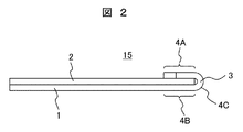
- FIG. 2 is a side view illustrating the terminal connection structure 15 described in the first embodiment.
- the terminal connection structure 15 has a flat plate-shaped first terminal 1 and a round bar-shaped second terminal 2, and the end of the first terminal 1 is bent at the end of the first terminal 1. ,
- the bent portion 3 is formed.
- the first terminal 1 has a flat plate shape having a bent portion 3
- the second terminal 2 has a round bar shape.
- the terminal connection structure 15 has a joint portion of dissimilar metals of aluminum or aluminum alloy and copper or copper alloy, and is a connection structure of dissimilar metals of aluminum or aluminum alloy and copper or copper alloy.
- the joint is a region where dissimilar metals of aluminum or an aluminum alloy and copper or a copper alloy are metal-bonded.
- the material of the first terminal 1 is industrial pure aluminum (A1050), and the first terminal 1 is a flat plate having a thickness of 1 mm and a width of 7 mm, and the surface is plated with nickel (Ni). Is given.
- the material of the second terminal 2 is oxygen-free copper (C1020), and the second terminal 2 is a round bar having a diameter of 1 mm and has a tin (Sn) plating on the surface. ..
- the surface of industrial pure aluminum (A1050) plated with nickel (Ni) is used for the first terminal 1, and the second terminal 2 is used.
- Oxygen-free copper (C1020) with tin (Sn) plating on the surface is used.
- the surface of the first terminal 1 does not necessarily have to be nickel (Ni) plated, and the surface of industrial pure aluminum (A1050) may not be nickel (Ni) plated.
- the surface of the terminal 2 of 2 does not necessarily have to be tin (Sn) plated, and an oxygen-free copper (C1020) having no tin (Sn) plating on the surface may be used.
- the bent portion 3 has a flat plate-shaped first portion 4A, a flat plate-shaped second portion 4B, and a bent-shaped third portion 4C. That is, at the end of the first terminal 1, the first portion 4A, the second portion 4B, and the third portion 4C are formed, and the bent portion 3 bent so as to sandwich the second terminal 2 is formed. Have.
- the material of the first terminal 1 and the material of the second terminal 2 are such that the first terminal 1 is made of aluminum or an aluminum alloy, and the second terminal 2 is a metal having a higher melting point than the first terminal 1. It consists of (eg, copper or copper alloy).
- the end of the second terminal 2 is sandwiched between the first portion 4A and the second portion 4B, and the end of the second terminal 2 is the bent portion 3, especially the first. It is joined to the portion 4A and the second portion 4B.
- the flat plate-shaped first terminal 1 and the round bar-shaped second terminal 2 are joined in the same direction. That is, the longitudinal direction of the first terminal 1 and the longitudinal direction of the second terminal 2 are the same (approximately parallel). That is, the second terminal 2 is arranged so as to extend substantially perpendicular to the bent bottom surface (third portion 4C) of the bent portion 3 of the first terminal 1.
- the aluminum or the like is formed. It is possible to improve the strength of the joints of dissimilar metals between aluminum alloys and copper or copper alloys, as well as the terminals and smoothing capacitors of bus bars that use aluminum or aluminum alloys and power modules that use copper or copper alloys. It is possible to improve the strength of the joint between the terminal and the terminal.
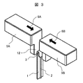
- FIG. 3 is a perspective view illustrating the resistance welding of the terminal connection structure 15 described in the first embodiment.
- FIG. 4 is a side view illustrating the resistance welding of the terminal connection structure 15 described in the first embodiment.
- the end portion of the second terminal 2 is sandwiched between the bent portion 3 formed at the end portion of the first terminal 1.
- the bent portion 3 sandwiching the end of the second terminal 2 is formed by a pair of resistance welding electrodes 5A (hereinafter, electrodes 5A) and resistance welding electrodes 5B (hereinafter, electrodes 5B). Insert it.
- the electrodes 5A and 5B are energized.
- the electrode 5A is pressurized in the electrode pressurizing direction 6A
- the electrode 5B is pressurized in the electrode pressurizing direction 6B. In this way, resistance welding can be performed by energizing and pressurizing.
- the electrode 5A pressurizes in the electrode pressurizing direction 6A
- the electrode 5B pressurizes in the electrode pressurizing direction 6B
- the bent portion 3 is pressurized from two directions, and the electrode 5A and the bent portion 3 (first portion). 4A), the end of the second terminal 2, the bent portion 3 (second portion 4B), and the electrode 5B are energized.
- the electrode pressurizing direction 6A and the electrode pressurizing direction 6B are opposite directions.
- resistance welding is performed with a current of 5 to 10 kA, an energization time of 100 to 300 ms, and an electrode pressing force of 150 to 170 N.
- the electrodes 5A and 5B each have a T-shaped facing surface thereof, and the bent portion 3 is sandwiched between the vertical bar portions (contact portions 12) of the respective T-shapes.
- the contact portion 12 has a planar shape. Then, in the first embodiment, the facing surface having the contact portion 12 is made of tungsten (W), and the other portion is made of a chromium copper alloy.
- the bent portion 3 and the end portion of the second terminal 2 When resistance welding is performed, the bent portion 3 and the end portion of the second terminal 2 generate heat due to electrical resistance and soften. Since the bent portion 3 has a melting point lower than that of the end portion of the second terminal 2, it is more likely to be softened than the end portion of the second terminal 2.
- the end portion of the second terminal 2 is sandwiched between the first portion 4A and the second portion 4B formed in the bent portion 3, and is further pressed by the electrodes 5A and 5B, so that the second terminal 2 has a second end portion.
- the end of the terminal 2 of 2 is buried in the first portion 4A and the second portion 4B.
- the surface of the first terminal 1 made of aluminum or an aluminum alloy is deformed, and the film of aluminum oxide formed on this surface is crushed accordingly, and the aluminum or the aluminum alloy inside the film and the second terminal 1 are crushed.
- Metallic bonding with the end of the terminal 2 is easy. Thereby, the strength of the joint portion between the first terminal 1 and the second terminal 2 can be improved.
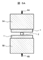
- FIG. 5A is a cross-sectional view illustrating the AA cross section (state before resistance welding) of FIG. 4 in the terminal connection structure 15 described in the first embodiment.
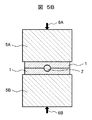
- FIG. 5B is a cross-sectional view illustrating the AA cross section (state after resistance welding) of FIG. 4 in the terminal connection structure 15 described in the first embodiment.
- the first portion 4A and the second portion 4B formed in the bent portion 3 are in contact with each other, and the first portion 4A and the first portion 4A and the first portion 4A and the first portion are around the end portion of the second terminal 2.
- a portion 4B of 2 is formed, and the bent portion 3 of the first terminal 1 completely wraps the end portion of the second terminal 2. Then, the end portion of the second terminal 2 is joined to the first portion 4A and the second portion 4B.
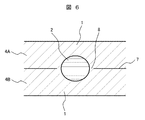
- FIG. 6 is a cross-sectional view illustrating a cross section of the terminal connection structure 15 (joint portion) described in the first embodiment.
- the first portion 4A and the second portion 4B of the bent portion 3 completely wrap around the end portion of the second terminal 2, and the end portion of the second terminal 2 is the second portion. It is joined to the first portion 4A and the second portion 4B.
- the end portion of the second terminal 2 is formed on a plane overlapping the contact interface 7 between the first portion 4A and the second portion 4B.
- the bent portion 3 of the first terminal 1 has a first portion 4A and a second portion 4B, and the end portion of the second terminal 2 has a first portion 4A and a second portion 4B. It is formed so as to pass through a plane overlapping the contact interface with.
- the terminal connection structure 15 described in the first embodiment is made of a first terminal 1 made of aluminum or an aluminum alloy and a metal having a higher melting point than the first terminal 1 (for example, copper or a copper alloy). It has a second terminal 2 and a bent portion 3 that sandwiches the end portion of the second terminal 2 at the end portion of the first terminal 1, and has a bent portion 3 and an end portion of the second terminal 2. Has a joint to be joined by resistance welding.
- the bent portion 3 formed at the end of the first terminal 1 made of aluminum or an aluminum alloy has a higher melting point than the first terminal 1.
- the end of the second terminal 2 made of metal for example, copper or a copper alloy
- the bent portion 3 sandwiching the end of the second terminal 2 is energized, and resistance welding is performed to pressurize the bent portion 3.
- the end of the second terminal 2 and the bent portion 3 are joined.
- FIG. 7A is a perspective view illustrating before the peeling test of the terminal connection structure 15 described in the first embodiment.
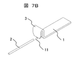
- FIG. 7B is a perspective view illustrating after the peeling test of the terminal connection structure 15 described in the first embodiment.
- the first terminal 1 and the second terminal 2 are bent 90 degrees as shown in FIG. 7A to apply a tensile load in the tensile direction 9A and the tensile direction 9B.
- the second terminal 2 breaks at the break position 11.
- the joint portion between the first terminal 1 and the second terminal 2 is not damaged, and the strength of the joint portion between the first terminal 1 and the second terminal 2 is improved. be able to.
- FIG. 13 is a perspective view illustrating a part of the power conversion device 100 described in the first embodiment.
- the power conversion device 100 is a device (inverter device) that is mounted on a hybrid vehicle or the like that generates a driving force by a motor and converts a direct current into an alternating current.
- the power conversion device 100 is a device that converts a direct current supplied from a direct current power source such as a battery into an alternating current and supplies it to a motor or the like, a plurality of power modules having a switching element or the like, and a plurality of smoothings. It consists of a capacitor, multiple bus bars, and a control circuit.
- the power conversion device 100 has a bus bar (DC bus bar) 17 for transmitting a direct current and an electronic component connected to the bus bar 17.
- the electronic component is a power module or a smoothing capacitor.
- the electronic component has a terminal to be joined to the bus bar 17.
- FIG. 13 shows a part of the power conversion device 100, and shows a molded capacitor 18 having a laminated structure, a smoothing capacitor 19A, and a smoothing capacitor 19B.
- the smoothing capacitor 19A has a terminal 20A made of copper (oxygen-free copper (C1020)), and the smoothing capacitor 19B has a terminal 20B made of copper (oxygen-free copper (C1020)).
- the terminal 20A and the terminal 20B are connected by using a bus bar 17 made of aluminum (industrial pure aluminum (A1050)).
- the terminals 20A and 20B have a round bar shape and the surface is plated with tin (Sn), and the bus bar 17 has a bent portion and is a flat plate, and the surface is plated with nickel (Ni). Has been done.
- the junction between the terminal 20A of the smoothing capacitor 19A and the terminal 20B of the smoothing capacitor 19B and the bus bar 17 is a junction of dissimilar metals of copper and aluminum.
- the terminal 20A of the smoothing capacitor 19A and the terminal 20A are formed. It is possible to improve the strength of the joint portion with the bus bar 17 and the joint portion between the terminal 20B of the smoothing capacitor 19B and the bus bar 17.
- bus bar 17 described in the first embodiment will be expanded and described.
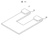
- FIG. 14 is a development diagram for explaining the development of the bus bar 17 described in the first embodiment.
- the bus bar 17 has a U-shape (U-shape). Then, at the two ends of the bus bar 17, a bent portion 3A and a bent portion 3B that sandwich the terminal 20A of the smoothing capacitor 19A and the terminal 20B of the smoothing capacitor 19B are formed.
- the terminal 20A of the smoothing capacitor 19A and the bent portion 3A of the bus bar 17 sandwiching the terminal 20A of the smoothing capacitor 19A are resistance-welded, and the terminal 20B of the smoothing capacitor 19B and the smoothing capacitor 19B are subjected to resistance welding.
- the bent portion 3B of the bus bar 17 that sandwiches the terminal 20B is resistance welded, and the smoothing capacitor 19A and the smoothing capacitor 19B are electrically connected.
- the power conversion device includes a bus bar 17 and an electronic component having a terminal to be joined to the bus bar 17, and the bus bar 17 is made of aluminum or an aluminum alloy and is an electronic component.
- the terminal is made of a metal (for example, copper or a copper alloy) having a melting point higher than that of the bus bar 17, and has a bent portion 3 at the end of the bus bar 17 that sandwiches the end of the terminal of the electronic component. It has a joint portion for joining the end portion of the bus and the bent portion 3 of the bus bar 17 by resistance welding.
- terminal 20A of the smoothing capacitor 19A is arranged so as to extend substantially perpendicular to the bending bottom surface (third portion 4C) in the bent portion 3A of the bus bar 17, and the terminal 20B of the smoothing capacitor 19B is provided on the bus bar. 17 is arranged so as to extend substantially perpendicular to the bent bottom surface (third portion 4C) of the bent portion 3B.
- the terminals of the electronic components are arranged so as to extend substantially perpendicular to the bent bottom surface of the bent portion 3 of the bus bar 17.
- bent portion 3A of the bus bar 17 and the bent portion 3B of the bus bar 17 are bent in the same direction.
- the strength of the joint between the terminal 20A of the smoothing capacitor 19A and the bent portion 3A of the bus bar 17 can be improved, and the strength of the joint between the terminal 20B of the smoothing capacitor 19B and the bent portion 3B of the bus bar 17 is improved. Can be made to.
- the smoothing capacitor can be efficiently arranged in the power conversion device 100.
- FIG. 8 is a perspective view illustrating the terminal connection structure 16 described in the comparative example.
- the terminal connection structure 16 has a flat plate-shaped first terminal 1 and a round bar-shaped second terminal 2.
- the bent portion 3 is not formed.
- the material of the first terminal 1 is industrial pure aluminum (A1050), and the first terminal 1 is a flat plate having a thickness of 1 mm and a width of 7 mm, and the surface is plated with nickel (Ni). Is given.
- the material of the second terminal 2 is oxygen-free copper (C1020), and the second terminal 2 is a round bar having a diameter of 1 mm and has a tin (Sn) plating on the surface. ..
- FIG. 9A is a cross-sectional view illustrating an AA cross section (before joining) similar to FIG. 5 in the terminal connection structure 16 described in the comparative example.
- FIG. 9B is a cross-sectional view illustrating an AA cross section (after joining) similar to FIG. 5 in the terminal connection structure 16 described in the comparative example.
- the end portion of the second terminal 2 is formed on the end portion of the first terminal 1.
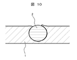
- FIG. 10 is a cross-sectional view illustrating a cross section of the terminal connection structure 16 (joint portion) described in the comparative example.
- the end portion of the first terminal 1 is formed around the end portion of the second terminal 2, and the end portion of the second terminal 2 is joined to the end portion of the first terminal 1. ..
- the comparative example although most of the second terminal 2 is buried in the first terminal 1, a part of the second terminal 2 is exposed.
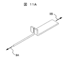
- FIG. 11A is a perspective view illustrating before the peeling test of the terminal connection structure 16 described in the comparative example.
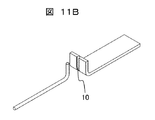
- FIG. 11B is a perspective view illustrating after the peeling test of the terminal connection structure 16 described in the comparative example.
- the first terminal 1 and the second terminal 2 are bent 90 degrees as shown in FIG. 11A to apply a tensile load in the tensile direction 9A and the tensile direction 9B.
- the first terminal 1 and the second terminal 2 are peeled off at the joint portion (peeling portion 10) between the first terminal 1 and the second terminal 2.
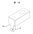
- FIG. 12 is a perspective view illustrating the resistance welding electrode 5 described in the second embodiment.
- the resistance welding electrode 5 described in Example 2 is different from the resistance welding electrode 5 described in Example 1 in the shape of the contact portion 12.
- the contact portion 12 has a planar shape, but in the resistance welding electrode 5 described in the second embodiment, a spherical protrusion 13 is formed on the contact portion 12. Will be done.
- the resistance welding electrode 5 described in the second embodiment has a spherical protrusion 13 at the contact portion 12, and the protrusion 13 pressurizes the bent portion 3.
- the bent portion 3 can be efficiently pressurized.
- the protrusion 13 has a circular shape, and its dimensions are 5 mm in diameter. The radius of curvature of the spherical portion is 25 mm.
- the protrusion 13 is made of tungsten (W).
- the present invention is not limited to the above-described embodiment, but includes various modifications.
- the above-described embodiment has been specifically described in order to explain the present invention in an easy-to-understand manner, and is not necessarily limited to the one having all the described configurations.
Landscapes
- Engineering & Computer Science (AREA)
- Manufacturing & Machinery (AREA)
- Connections Effected By Soldering, Adhesion, Or Permanent Deformation (AREA)
- Manufacturing Of Electrical Connectors (AREA)
- Connection Of Batteries Or Terminals (AREA)
Abstract
本発明は、アルミニウムやアルミニウム合金と銅や銅合金との異種金属の接合部の強度を向上させる端子接続構造を提供する。本発明の端子接続構造は、アルミニウム又はアルミニウム合金からなる第1の端子と、第1の端子よりも融点が高い金属からなる第2の端子と、を有し、第1の端子の端部に、第2の端子の端部を挟み込む屈曲部を有し、第2の端子の端部と屈曲部とを抵抗溶接により接合する接合部を有することを特徴とする。
Description
本発明は、直流電流を交流電流に変換する電力変換装置の端子接続構造、端子接続構造の製造方法、及び電力変換装置に関する。
モータで駆動力を発生するハイブリッド自動車などは、直流電流を交流電流に変換する電力変換装置(インバータ装置)を有する。
電力変換装置は、バッテリなどの直流電源から供給される直流電流を、交流電流に変換し、モータなどへ供給する装置であり、スイッチング素子などを有する複数のパワーモジュール、複数の平滑化コンデンサ、複数のバスバ(bus bar)、制御回路などで構成される。
特に、バスバは、パワーモジュール同士や平滑コンデンサ同士を電気的に接続する部品である。バスバには、一般的に、銅や銅合金が使用される。しかし、バスバには、銅や銅合金よりも、安価で比重が小さいアルミニウムやアルミニウム合金が使用される場合があり、これにより、電力変換装置の価格を低減し、電力変換装置の軽量化を実現する。
しかし、パワーモジュールの端子や平滑コンデンサの端子には、一般的に銅や銅合金が使用されるため、バスバにアルミニウムやアルミニウム合金を使用する場合には、パワーモジュールの端子や平滑コンデンサの端子とバスバとの接合部は、銅とアルミニウムとの異種金属の接合となる。
このような異種金属の接合に、アーク溶接やレーザ溶接に代表される溶融溶接を使用すると、硬質で延性に乏しい金属間化合物が生成されるため、接合部の疲労特性が低下する恐れがある。
このため、アルミニウムやアルミニウム合金が使用されるバスバと、銅や銅合金が使用されるパワーモジュールの端子や平滑コンデンサの端子と、を接続する場合には、接続方法が課題となる。
なお、溶接強度のバラツキを抑制し、安全で強固な電気的接続を確保する結線構造の製造方法として、特開2004-319443号公報(特許文献1)がある。
この特許文献1には、金属材料によって形成された導線と、燃焼-赤外線吸収法による組成分析によって炭素原子の含有が認められない金属材料によって形成された金属板と、を結線するため、先ず、金属板の端部を屈曲させ、導線の挟み込みが可能な屈曲部を形成し、次に、屈曲部に導線を挟み、次に、屈曲部に挟まれた導線に接触していない面から加熱し、屈曲部を導線に融着させる結線構造の製造方法が記載されている(要約参照)。
そして、特許文献1には、導線に鉄又は鉄合金が使用され、金属板に純銅、リン青銅、ベリリウム銅合金、チタン銅合金、洋白、アルミ青銅、黄銅、丹銅、又は白銅が使用されることが記載されている(段落0018参照)。
特許文献1には、銅や銅合金が使用される金属板の端部に屈曲部を形成し、屈曲部に鉄や鉄合金が使用される導線を挟み、屈曲部を導線に融着させる結線構造の製造方法が記載されている。
しかし、特許文献1には、アルミニウムやアルミニウム合金が使用されるバスバと、銅や銅合金が使用されるパワーモジュールの端子や平滑コンデンサの端子と、を接続する場合の接続方法は、記載されていない。
そして、特許文献1には、銅とアルミニウムとの異種金属を接合する場合、接合部の強度が低下するとの課題については、記載されていない。
一般的に、アルミニウムやアルミニウム合金の表面は、酸化アルミニウムで覆われている。酸化アルミニウムの融点は、2000℃以上であり、530℃~660℃程度であるアルミニウムやアルミニウム合金の融点よりも、1400℃程度、高い。
アルミニウムやアルミニウム合金を加熱し、溶融させても、酸化アルミニウムは溶融せず、表面を覆ったままとなる。このため、金属板と導線との境界には、酸化アルミニウムが介在し、金属結合を妨げることになる。この結果、接合部の強度が低下する。
なお、銅や銅合金の表面は、酸化銅で覆われている。酸化銅の融点は、1000℃程度であり、銅や銅合金の融点と同程度であるため、銅や銅合金を溶融させた際に、酸化銅も溶融するため、金属結合を妨げることはない。
そこで、本発明は、アルミニウムやアルミニウム合金と銅や銅合金との異種金属の接合部の強度を向上させる端子接続構造、端子接続構造の製造方法、及び電力変換装置を提供する。
上記した課題を解決するため、本発明の端子接続構造は、アルミニウム又はアルミニウム合金からなる第1の端子と、第1の端子よりも融点が高い金属からなる第2の端子と、を有し、第1の端子の端部に、第2の端子の端部を挟み込む屈曲部を有し、第2の端子の端部と屈曲部とを抵抗溶接により接合する接合部を有することを特徴とする。
また、本発明の端子接続構造の製造方法は、アルミニウム又はアルミニウム合金からなる第1の端子の端部に形成される屈曲部に、第1の端子よりも融点が高い金属からなる第2の端子の端部を挟み込み、第2の端子の端部を挟み込んだ屈曲部に通電し、屈曲部を加圧する抵抗溶接を施し、第2の端子の端部と屈曲部と接合することを特徴とする。
また、本発明の電力変換装置は、電流を伝達するバスバと、バスバと接合する端子を有する電子部品と、を有し、バスバは、アルミニウム又はアルミニウム合金により構成され、端子は、バスバよりも融点が高い金属により構成され、バスバの端部に、端子の端部を挟み込む屈曲部を有し、端子の端部と屈曲部とを抵抗溶接により接合する接合部を有することを特徴とする。
本発明によれば、アルミニウムやアルミニウム合金と銅や銅合金との異種金属の接合部の強度を向上させる端子接続構造、端子接続構造の製造方法、及び電力変換装置を提供することができる。
なお、上記した以外の課題、構成及び効果については、下記する実施例の説明により、明らかにされる。
以下、本発明の実施例を、図面を使用して、説明する。なお、実質的に同一又は類似する構成には、同一の符号を付し、説明が重複する場合には、その説明を省略する場合がある。
先ず、実施例1に記載する端子接続構造15を説明する。
図1は、実施例1に記載する端子接続構造15を説明する斜視図である。
図2は、実施例1に記載する端子接続構造15を説明する側面図である。
端子接続構造15は、平板状の第1の端子1と丸棒状の第2の端子2とを有し、第1の端子1の端部には、第1の端子1の端部を折り曲げて、屈曲部3が形成される。このように、第1の端子1は、屈曲部3を有する平板状であり、第2の端子2は、丸棒状である。
つまり、端子接続構造15は、アルミニウムやアルミニウム合金と銅や銅合金との異種金属の接合部を有し、アルミニウムやアルミニウム合金と銅や銅合金との異種金属の接続構造である。
なお、接合部とは、アルミニウムやアルミニウム合金と銅や銅合金との異種金属が、金属結合する領域である。
第1の端子1の材質は、工業用純アルミニウム(A1050)であり、第1の端子1には、厚みが1mm、幅が7mmの平板状のものが使用され、表面にニッケル(Ni)めっきが施されている。
第2の端子2の材質は、無酸素銅(C1020)であり、第2の端子2には、直径が1mmの丸棒状のものが使用され、表面に錫(Sn)めっきが施されている。
なお、このように、実施例1では、第1の端子1には、工業用純アルミニウム(A1050)の表面にニッケル(Ni)めっきを施しているものを使用し、第2の端子2には、無酸素銅(C1020)の表面に錫(Sn)めっきを施しているものを使用している。
しかし、第1の端子1について、必ずしも表面にニッケル(Ni)めっきを施す必要はなく、工業用純アルミニウム(A1050)の表面にニッケル(Ni)めっきを施さないものを使用してもよく、第2の端子2について、必ずしも表面に錫(Sn)めっきを施す必要はなく、無酸素銅(C1020)の表面に錫(Sn)めっきを施さないものを使用してもよい。
そして、第2の端子2の端部(屈曲部3に挿入される部分)は、第1の端子1の端部に形成される屈曲部3に挿入される。この屈曲部3は、平板状の第1の部分4Aと、平板状の第2の部分4Bと、屈曲状の第3の部分4Cと、を有する。つまり、第1の端子1の端部は、第1の部分4Aと第2の部分4Bと第3の部分4Cとが形成され、第2の端子2を挟み込むように折り曲げられた屈曲部3を有する。
なお、第1の端子1の材質と第2の端子2の材質とは、第1の端子1がアルミニウム又はアルミニウム合金からなり、第2の端子2が第1の端子1よりも融点が高い金属(例えば、銅又は銅合金)からなる。
つまり、第2の端子2の端部は、第1の部分4Aと第2の部分4Bとの間に挟み込まれ、第2の端子2の端部は、屈曲部3と、特に、第1の部分4Aと第2の部分4Bと、に接合する。
また、平板状の第1の端子1と丸棒状の第2の端子2とは、同一方向に接合される。つまり、第1の端子1の長手方向と第2の端子2の長手方向とが同一(概略平行)である。
つまり、第2の端子2は、第1の端子1の屈曲部3における曲げ底面(第3の部分4C)に対して、概略垂直に延在するように配置される。
つまり、第2の端子2は、第1の端子1の屈曲部3における曲げ底面(第3の部分4C)に対して、概略垂直に延在するように配置される。
このように、実施例1によれば、第2の端子2を、屈曲部3における曲げ底面(第3の部分4C)に対して、概略垂直に延在するように配置することにより、アルミニウムやアルミニウム合金と銅や銅合金との異種金属の接合部の強度を向上させることができると共に、アルミニウムやアルミニウム合金が使用されるバスバと、銅や銅合金が使用されるパワーモジュールの端子や平滑コンデンサの端子と、の接合部の強度を向上させることができる。
次に、実施例1に記載する端子接続構造15の抵抗溶接を説明する。
図3は、実施例1に記載する端子接続構造15の抵抗溶接を説明する斜視図である。
図4は、実施例1に記載する端子接続構造15の抵抗溶接を説明する側面図である。
抵抗溶接を施す場合、
(1)先ず、第1の端子1の端部に形成される屈曲部3に、第2の端子2の端部を挟み込む。
(2)次に、第2の端子2の端部を挟み込んだ屈曲部3を、1対の抵抗溶接用電極5A(以下、電極5A)と抵抗溶接用電極5B(以下、電極5B)とで挟み込む。
(3)次に、電極5Aと電極5Bとに、通電する。そして、同時に、電極5Aを電極加圧方向6Aに、電極5Bを電極加圧方向6Bに、加圧する。このように、通電し、加圧することにより、抵抗溶接を施すことができる。
(1)先ず、第1の端子1の端部に形成される屈曲部3に、第2の端子2の端部を挟み込む。
(2)次に、第2の端子2の端部を挟み込んだ屈曲部3を、1対の抵抗溶接用電極5A(以下、電極5A)と抵抗溶接用電極5B(以下、電極5B)とで挟み込む。
(3)次に、電極5Aと電極5Bとに、通電する。そして、同時に、電極5Aを電極加圧方向6Aに、電極5Bを電極加圧方向6Bに、加圧する。このように、通電し、加圧することにより、抵抗溶接を施すことができる。
つまり、電極5Aは、電極加圧方向6Aに加圧し、電極5Bは、電極加圧方向6Bに加圧し、屈曲部3は二方向から加圧され、電極5A、屈曲部3(第1の部分4A)、第2の端子2の端部、屈曲部3(第2の部分4B)、電極5Bが通電される。
これにより、第1の部分4Aと、第2の端子2の端部と、第2の部分4Bと、を接合することができる。なお、電極加圧方向6Aと電極加圧方向6Bとは、対向する方向である。
なお、具体的には、電流5~10kA、通電時間100~300ms、電極加圧力150~170Nで、抵抗溶接を施す。
また、電極5Aと電極5Bとは、それぞれ、その対向面がT字形状を有し、それぞれのT字形状の縦棒部分(接触部12)で、屈曲部3を挟み込む。
なお、実施例1では、接触部12は、平面形状を有する。そして、実施例1では、接触部12を有する対向面は、タングステン(W)で構成され、それ以外の部分は、クロム銅合金で構成される。
抵抗溶接を施す場合には、屈曲部3と第2の端子2の端部とが電気抵抗で発熱し、軟化する。そして、屈曲部3は、第2の端子2の端部よりも、融点が低いため、第2の端子2の端部よりも、軟化しやすい。
第2の端子2の端部は、屈曲部3に形成される第1の部分4Aと第2の部分4Bとに挟み込まれ、更に、電極5Aと電極5Bとから、加圧されるため、第2の端子2の端部は、第1の部分4Aと第2の部分4Bとに埋没する。
この際、アルミニウム又はアルミニウム合金からなる第1の端子1の表面が変形し、これに伴い、この表面に形成される酸化アルミニウムの被膜が破砕し、被膜内部のアルミニウム又はアルミニウム合金と、第2の端子2の端部とが金属結合しやすくなる。これにより、第1の端子1と第2の端子2との接合部の強度を向上させることができる。
次に、実施例1に記載する端子接続構造15における図4のA-A断面を説明する。
図5Aは、実施例1に記載する端子接続構造15における図4のA-A断面(抵抗溶接前の状態)を説明する断面図である。
図5Bは、実施例1に記載する端子接続構造15における図4のA-A断面(抵抗溶接後の状態)を説明する断面図である。
抵抗溶接前の状態では、第2の端子2の端部は、第1の端子1の端部に形成される屈曲部3に挟み込まれる。
抵抗溶接後の状態では、屈曲部3に形成される第1の部分4Aと第2の部分4Bとが接触し、第2の端子2の端部の周囲には、第1の部分4Aと第2の部分4Bとが形成され、第2の端子2の端部を第1の端子1の屈曲部3が完全に包み込む。そして、第2の端子2の端部は、第1の部分4Aと第2の部分4Bとに接合する。
次に、実施例1に記載する端子接続構造15(接合部)の断面を説明する。
図6は、実施例1に記載する端子接続構造15(接合部)の断面を説明する断面図である。
なお、この断面の観察方向は、図5Aや図5Bと同一である。
実施例1では、第2の端子2の端部の周囲を、屈曲部3の第1の部分4Aと第2の部分4Bとが、完全に包み込み、第2の端子2の端部は、第1の部分4Aと第2の部分4Bとに接合する。
つまり、第2の端子2の端部は、第1の部分4Aと第2の部分4Bとの接触界面7と重なる平面に形成される。そして、第1の端子1の屈曲部3は、第1の部分4Aと第2の部分4Bとを有し、第2の端子2の端部は、第1の部分4Aと第2の部分4Bとの接触界面と重なる平面を通るように形成される。
そして、第2の端子2の端部の周囲(近傍)には、接触界面7が形成されない領域8が観察される。そして、接触界面7が形成されない領域8では、第1の部分4Aと第2の部分4Bとの金属結合が観察され、第1の部分4Aと第2の部分4Bとを強固に接合している。
このように、実施例1に記載する端子接続構造15は、アルミニウム又はアルミニウム合金からなる第1の端子1と、第1の端子1よりも融点が高い金属(例えば、銅又は銅合金)からなる第2の端子2と、を有し、第1の端子1の端部に、第2の端子2の端部を挟み込む屈曲部3を有し、第2の端子2の端部と屈曲部3とを抵抗溶接により接合する接合部を有する。
これにより、アルミニウムやアルミニウム合金と銅や銅合金との異種金属の接合部の強度を向上させることができる。
また、実施例1に記載する端子接続構造15の製造方法は、アルミニウム又はアルミニウム合金からなる第1の端子1の端部に形成される屈曲部3に、第1の端子1よりも融点が高い金属(例えば、銅又は銅合金)からなる第2の端子2の端部を挟み込み、第2の端子2の端部を挟み込んだ屈曲部3に通電し、屈曲部3を加圧する抵抗溶接を施し、第2の端子2の端部と屈曲部3と接合する。
これにより、アルミニウムやアルミニウム合金と銅や銅合金との異種金属を強固に接合することができる。
次に、実施例1に記載する端子接続構造15の引き剥がし試験前後を説明する。
図7Aは、実施例1に記載する端子接続構造15の引き剥がし試験前を説明する斜視図である。
図7Bは、実施例1に記載する端子接続構造15の引き剥がし試験後を説明する斜視図である。
抵抗溶接後に、第1の端子1及び第2の端子2を、図7Aに示すように、90度曲げて、引張方向9A及び引張方向9Bに、引張荷重を付与する。この結果、図7Bに示すように、第2の端子2が、破断位置11で、破断する。
このように、実施例1では、第1の端子1と第2の端子2との接合部は、破損せず、第1の端子1と第2の端子2との接合部の強度を向上させることができる。
次に、実施例1に記載する電力変換装置100の一部を説明する。
図13は、実施例1に記載する電力変換装置100の一部を説明する斜視図である。
電力変換装置100は、モータで駆動力を発生するハイブリッド自動車などに搭載され、直流電流を交流電流に変換する装置(インバータ装置)である。
つまり、電力変換装置100は、バッテリなどの直流電源から供給される直流電流を、交流電流に変換し、モータなどへ供給する装置であり、スイッチング素子などを有する複数のパワーモジュール、複数の平滑化コンデンサ、複数のバスバ、制御回路などで構成される。
電力変換装置100は、直流電流を伝達するバスバ(直流バスバ)17と、バスバ17に接続する電子部品と、を有する。ここで、電子部品とは、パワーモジュール又は平滑化コンデンサである。そして、電子部品は、バスバ17と接合する端子を有する。
図13は、電力変換装置100の一部を示すものであり、積層構造のモールドコンデンサ18と平滑化コンデンサ19Aと平滑コンデンサ19Bとを示す。平滑化コンデンサ19Aは、銅(無酸素銅(C1020))からなる端子20Aを有し、平滑化コンデンサ19Bは、銅(無酸素銅(C1020))からなる端子20Bを有する。
そして、端子20Aと端子20Bとを、アルミニウム(工業用純アルミニウム(A1050))からなるバスバ17を使用し、接続する。
この際、端子20A及び端子20Bは、丸棒状であり、表面に錫(Sn)めっきが施され、バスバ17は、屈曲部を有し、平板状であり、表面にニッケル(Ni)めっきが施されている。
つまり、平滑コンデンサ19Aの端子20A及び平滑コンデンサ19Bの端子20Bと、バスバ17との接合部は、銅とアルミニウムとの異種金属の接合となる。
そして、平滑コンデンサ19Aの端子20Aとバスバ17との接合部に、及び、平滑コンデンサ19Bの端子20Bとバスバ17との接合部に、上記した抵抗溶接を施すことにより、平滑コンデンサ19Aの端子20Aとバスバ17との接合部、及び、平滑コンデンサ19Bの端子20Bとバスバ17との接合部、の強度を向上させることができる。
次に、実施例1に記載するバスバ17を展開して説明する。
図14は、実施例1に記載するバスバ17を展開して説明する展開図である。
バスバ17は、コの字形状(U字形状)を有する。そして、バスバ17の2つの端部には、平滑コンデンサ19Aの端子20A、及び、平滑コンデンサ19Bの端子20Bを、挟み込む屈曲部3A及び屈曲部3Bが形成される。
このように、実施例1では、平滑コンデンサ19Aの端子20Aと、平滑コンデンサ19Aの端子20Aを挟み込むバスバ17の屈曲部3Aと、を抵抗溶接し、平滑コンデンサ19Bの端子20Bと、平滑コンデンサ19Bの端子20Bを挟み込むバスバ17の屈曲部3Bと、を抵抗溶接し、平滑コンデンサ19Aと平滑コンデンサ19Bとを電気的に接続する。
このように、実施例1に記載する電力変換装置は、バスバ17と、バスバ17と接合する端子を有する電子部品と、を有し、バスバ17は、アルミニウム又はアルミニウム合金により構成され、電子部品の端子は、バスバ17よりも融点が高い金属(例えば、銅又は銅合金)により構成され、バスバ17の端部に、電子部品の端子の端部を挟み込む屈曲部3を有し、電子部品の端子の端部とバスバ17の屈曲部3とを抵抗溶接により接合する接合部を有する。
また、平滑コンデンサ19Aの端子20Aを、バスバ17の屈曲部3Aにおける曲げ底面(第3の部分4C)に対して、概略垂直に延在するように配置し、平滑コンデンサ19Bの端子20Bを、バスバ17の屈曲部3Bにおける曲げ底面(第3の部分4C)に対して、概略垂直に延在するように配置する。
つまり、電子部品の端子は、バスバ17の屈曲部3における曲げ底面に対して、概略垂直に延在するように配置される。
また、バスバ17の屈曲部3Aとバスバ17の屈曲部3Bとは、同一方向に屈曲する。
これにより、平滑コンデンサ19Aの端子20Aとバスバ17の屈曲部3Aとの接合部の強度を向上させることができ、平滑コンデンサ19Bの端子20Bとバスバ17の屈曲部3Bとの接合部の強度を向上させることができる。
そして、更に、平滑コンデンサを、効率よく、電力変換装置100に配置することができる。
なお、実施例1では、平滑化コンデンサについて説明したが、パワーモジュールについても同様である。
≪比較例≫
次に、比較例に記載する端子接続構造16を説明する。
≪比較例≫
次に、比較例に記載する端子接続構造16を説明する。
図8は、比較例に記載する端子接続構造16を説明する斜視図である。
端子接続構造16は、平板状の第1の端子1と丸棒状の第2の端子2とを有する。なお、屈曲部3は形成しない。
第1の端子1の材質は、工業用純アルミニウム(A1050)であり、第1の端子1には、厚みが1mm、幅が7mmの平板状のものが使用され、表面にニッケル(Ni)めっきが施されている。
第2の端子2の材質は、無酸素銅(C1020)であり、第2の端子2には、直径が1mmの丸棒状のものが使用され、表面に錫(Sn)めっきが施されている。
次に、比較例に記載する端子接続構造16における図5と同様のA-A断面を説明する。
図9Aは、比較例に記載する端子接続構造16における図5と同様のA-A断面(接合前)を説明する断面図である。
図9Bは、比較例に記載する端子接続構造16における図5と同様のA-A断面(接合後)を説明する断面図である。
接合前の状態では、第2の端子2の端部は、第1の端子1の端部上に形成される。
接合後の状態では、第2の端子2の端部が、第1の端子1の端部に、めり込む。そして、第2の端子2の端部は、第1の端子1の端部に、接合する。
次に、比較例に記載する端子接続構造16(接合部)の断面を説明する。
図10は、比較例に記載する端子接続構造16(接合部)の断面を説明する断面図である。
なお、この断面の観察方向は、図9Aや図9Bと同一である。
比較例では、第2の端子2の端部の周囲に、第1の端子1の端部が形成され、第2の端子2の端部は、第1の端子1の端部に、接合する。しかし、比較例では、第2の端子2の大部分が、第1の端子1に埋没しているものの、一部が露出する。
次に、比較例に記載する端子接続構造16の引き剥がし試験前後を説明する。
図11Aは、比較例に記載する端子接続構造16の引き剥がし試験前を説明する斜視図である。
図11Bは、比較例に記載する端子接続構造16の引き剥がし試験後を説明する斜視図である。
接合後に、第1の端子1及び第2の端子2を、図11Aに示すように、90度曲げて、引張方向9A及び引張方向9Bに、引張荷重を付与する。この結果、図11Bに示すように、第1の端子1と第2の端子2との接合部(剥離部10)で、第1の端子1と第2の端子2とが剥離する。
次に、実施例2に記載する抵抗溶接用電極5を説明する。
図12は、実施例2に記載する抵抗溶接用電極5を説明する斜視図である。
実施例2に記載する抵抗溶接用電極5は、実施例1に記載する抵抗溶接用電極5に比較し、接触部12の形状が相違する。実施例1に記載する抵抗溶接用電極5は、接触部12が平面形状であるが、実施例2に記載する抵抗溶接用電極5は、接触部12に、球面状の突起部13が、形成される。
つまり、実施例2に記載する抵抗溶接用電極5は、接触部12に、球面状の突起部13を有し、この突起部13が、屈曲部3を加圧する。これにより、屈曲部3を効率よく加圧することができる。
なお、突起部13は、円形形状であり、その寸法は、直径5mmである。また、球面状の部分の曲率半径は、25mmである。そして、突起部13は、タングステン(W)で構成される。
なお、本発明は上記した実施例に限定されるものではなく、様々な変形例が含まれる。例えば、上記した実施例は本発明を分かりやすく説明するために、具体的に説明したものであり、必ずしも説明した全ての構成を有するものに限定されるものではない。
また、ある実施例の構成の一部を、他の実施例の構成の一部に置換することもできる。また、ある実施例の構成に他の実施例の構成を追加することもできる。また、各実施例の構成の一部について、それを削除し、他の構成の一部を追加し、他の構成の一部と置換することもできる。
1…第1の端子、2…第2の端子、3…屈曲部、3A…屈曲部、3B…屈曲部、4A…第1の部分、4B…第2の部分、4C…第3の部分、5…抵抗溶接用電極、5A…電極、5B…電極、6A…電極加圧方向、6B…電極加圧方向、7…接触界面、8…領域、9A…引張方向、9B…引張方向、10…剥離部、11…破断位置、12…接触部、13…突起部、15…端子接続構造、16…端子接続構造、17…バスバ、18…モールドコンデンサ、19A…平滑コンデンサ、19B…平滑コンデンサ、20A…端子、20B…端子、100…電力変換装置。
Claims (9)
- アルミニウム又はアルミニウム合金からなる第1の端子と、前記第1の端子よりも融点が高い金属からなる第2の端子と、を有し、
前記第1の端子の端部に、前記第2の端子の端部を挟み込む屈曲部を有し、
前記第2の端子の端部と前記屈曲部とを抵抗溶接により接合する接合部を有することを特徴とする端子接続構造。 - 請求項1に記載する端子接続構造であって、
前記第1の端子の屈曲部は、第1の部分と第2の部分とを有し、
前記第2の端子の端部は、前記第1の部分と前記第2の部分との接触界面と重なる平面を通るように形成されることを特徴とする端子接続構造。 - 請求項1に記載する端子接続構造であって、
前記第1の端子は、屈曲部を有する平板状であり、前記第2の端子は、丸棒状であることを特徴とする端子接続構造。 - 請求項1に記載する端子接続構造であって、
前記第2の端子は、銅又は銅合金からなることを特徴とする端子接続構造。 - 請求項1に記載する端子接続構造であって、
前記第2の端子は、前記第1の端子の屈曲部における曲げ底面に対して、垂直に延在するように配置されることを特徴とする端子接続構造。 - アルミニウム又はアルミニウム合金からなる第1の端子の端部に形成される屈曲部に、前記第1の端子よりも融点が高い金属からなる第2の端子の端部を挟み込み、
前記第2の端子の端部を挟み込んだ前記屈曲部に通電し、前記屈曲部を加圧する抵抗溶接を施し、前記第2の端子の端部と前記屈曲部と接合することを特徴とする端子接続構造の製造方法。 - 電流を伝達するバスバと、前記バスバと接合する端子を有する電子部品と、を有する電力変換装置であって、
前記バスバは、アルミニウム又はアルミニウム合金により構成され、前記端子は、前記バスバよりも融点が高い金属により構成され、
前記バスバの端部に、前記端子の端部を挟み込む屈曲部を有し、
前記端子の端部と前記屈曲部とを抵抗溶接により接合する接合部を有することを特徴とする電力変換装置。 - 請求項7に記載する電力変換装置であって、
前記端子は、銅又は銅合金により構成されることを特徴とする電力変換装置。 - 請求項8に記載する電力変換装置であって、
前記端子は、前記屈曲部における曲げ底面に対して、垂直に延在するように配置されることを特徴とする電力変換装置。
Applications Claiming Priority (2)
| Application Number | Priority Date | Filing Date | Title |
|---|---|---|---|
| JP2020-118255 | 2020-07-09 | ||
| JP2020118255A JP2022015430A (ja) | 2020-07-09 | 2020-07-09 | 端子接続構造、端子接続構造の製造方法、及び電力変換装置 |
Publications (1)
| Publication Number | Publication Date |
|---|---|
| WO2022009498A1 true WO2022009498A1 (ja) | 2022-01-13 |
Family
ID=79552887
Family Applications (1)
| Application Number | Title | Priority Date | Filing Date |
|---|---|---|---|
| PCT/JP2021/015745 Ceased WO2022009498A1 (ja) | 2020-07-09 | 2021-04-16 | 端子接続構造、端子接続構造の製造方法、及び電力変換装置 |
Country Status (2)
| Country | Link |
|---|---|
| JP (1) | JP2022015430A (ja) |
| WO (1) | WO2022009498A1 (ja) |
Cited By (1)
| Publication number | Priority date | Publication date | Assignee | Title |
|---|---|---|---|---|
| CN116565818A (zh) * | 2022-01-28 | 2023-08-08 | 东莞令特电子有限公司 | 用于电涌保护装置的高钎焊强度端子 |
Citations (4)
| Publication number | Priority date | Publication date | Assignee | Title |
|---|---|---|---|---|
| JPS5578477A (en) * | 1978-12-08 | 1980-06-13 | Matsushita Electric Works Ltd | Structure for connecting lead wire to terminal and method of connecting same |
| JP2008193767A (ja) * | 2007-02-01 | 2008-08-21 | Mitsubishi Heavy Ind Ltd | バスバー接続構造およびインバータ一体型電動圧縮機 |
| JP2013016346A (ja) * | 2011-07-04 | 2013-01-24 | Sumitomo Wiring Syst Ltd | バスバーとリード線との接続構造 |
| JP2020011287A (ja) * | 2018-07-20 | 2020-01-23 | オリンパス株式会社 | 接合体の製造方法および接合体 |
-
2020
- 2020-07-09 JP JP2020118255A patent/JP2022015430A/ja active Pending
-
2021
- 2021-04-16 WO PCT/JP2021/015745 patent/WO2022009498A1/ja not_active Ceased
Patent Citations (4)
| Publication number | Priority date | Publication date | Assignee | Title |
|---|---|---|---|---|
| JPS5578477A (en) * | 1978-12-08 | 1980-06-13 | Matsushita Electric Works Ltd | Structure for connecting lead wire to terminal and method of connecting same |
| JP2008193767A (ja) * | 2007-02-01 | 2008-08-21 | Mitsubishi Heavy Ind Ltd | バスバー接続構造およびインバータ一体型電動圧縮機 |
| JP2013016346A (ja) * | 2011-07-04 | 2013-01-24 | Sumitomo Wiring Syst Ltd | バスバーとリード線との接続構造 |
| JP2020011287A (ja) * | 2018-07-20 | 2020-01-23 | オリンパス株式会社 | 接合体の製造方法および接合体 |
Cited By (1)
| Publication number | Priority date | Publication date | Assignee | Title |
|---|---|---|---|---|
| CN116565818A (zh) * | 2022-01-28 | 2023-08-08 | 东莞令特电子有限公司 | 用于电涌保护装置的高钎焊强度端子 |
Also Published As
| Publication number | Publication date |
|---|---|
| JP2022015430A (ja) | 2022-01-21 |
Similar Documents
| Publication | Publication Date | Title |
|---|---|---|
| CN107438887B (zh) | 超导线和用于制造超导线的方法 | |
| US4034152A (en) | Termination system for fusing aluminum-type lead wires | |
| KR20060129364A (ko) | 알루미늄 전도체에 대한 단자의 연결방법과 이러한 방법에 의하여 구성된 전도체 | |
| US6655968B2 (en) | Circuit having bus bars and junction box containing the circuit | |
| CN107615590B (zh) | 接线端子以及接线端子与电线的接合方法 | |
| WO2016017013A1 (ja) | 端子と電線の接合方法および電線接続用の端子 | |
| JP5989511B2 (ja) | 電線と端子の接続方法 | |
| JP2010257843A (ja) | ターミナル、モータ及び電気機器 | |
| JPH10328862A (ja) | レーザ溶接方法 | |
| JP2022015430A (ja) | 端子接続構造、端子接続構造の製造方法、及び電力変換装置 | |
| JP2023161114A (ja) | バスバー及びそれを備えた組電池 | |
| WO2014077144A1 (ja) | 端子金具付き電線 | |
| JP6116740B1 (ja) | 平編組線およびその製造方法 | |
| JP3174286B2 (ja) | レーザ溶接構造 | |
| JPH11176552A (ja) | 端子と導体の接続方法 | |
| JP3179002B2 (ja) | 導体間の接合方法及び導体間の接合構造 | |
| JP3566914B2 (ja) | 端子の接続方法 | |
| JP2001229751A (ja) | 可とう電気導体の両端部の圧着接合方法 | |
| JP7041180B2 (ja) | 電線の接続構造及び接続方法 | |
| JP2019117704A (ja) | 導電性金属端子、導電性金属端子付きアルミニウム電線、及び導電性金属端子付きアルミニウム電線の製造方法 | |
| JP2002008816A (ja) | 電気接続用導体片の接合方法および導体片接合用補強片 | |
| WO2013183160A1 (ja) | 端子金具付き電線及び端子金具付き電線の製造方法 | |
| JP2000067943A (ja) | 電気的接続部品 | |
| JP6177394B1 (ja) | 導体製造方法および導体 | |
| JP2842507B2 (ja) | 電導線と接続端子の結合方法及び接続構造 |
Legal Events
| Date | Code | Title | Description |
|---|---|---|---|
| 121 | Ep: the epo has been informed by wipo that ep was designated in this application |
Ref document number: 21837779 Country of ref document: EP Kind code of ref document: A1 |
|
| NENP | Non-entry into the national phase |
Ref country code: DE |
|
| 122 | Ep: pct application non-entry in european phase |
Ref document number: 21837779 Country of ref document: EP Kind code of ref document: A1 |