WO2022009292A1 - 波長クロスコネクト装置、マルチバンド伝送システム及びマルチバンド伝送方法 - Google Patents
波長クロスコネクト装置、マルチバンド伝送システム及びマルチバンド伝送方法 Download PDFInfo
- Publication number
- WO2022009292A1 WO2022009292A1 PCT/JP2020/026498 JP2020026498W WO2022009292A1 WO 2022009292 A1 WO2022009292 A1 WO 2022009292A1 JP 2020026498 W JP2020026498 W JP 2020026498W WO 2022009292 A1 WO2022009292 A1 WO 2022009292A1
- Authority
- WO
- WIPO (PCT)
- Prior art keywords
- wavelength
- band
- optical
- optical signal
- input
- Prior art date
- Legal status (The legal status is an assumption and is not a legal conclusion. Google has not performed a legal analysis and makes no representation as to the accuracy of the status listed.)
- Ceased
Links
Images


Classifications
-
- H—ELECTRICITY
- H04—ELECTRIC COMMUNICATION TECHNIQUE
- H04B—TRANSMISSION
- H04B10/00—Transmission systems employing electromagnetic waves other than radio-waves, e.g. infrared, visible or ultraviolet light, or employing corpuscular radiation, e.g. quantum communication
- H04B10/29—Repeaters
- H04B10/291—Repeaters in which processing or amplification is carried out without conversion of the main signal from optical form
- H04B10/293—Signal power control
-
- H—ELECTRICITY
- H04—ELECTRIC COMMUNICATION TECHNIQUE
- H04Q—SELECTING
- H04Q11/00—Selecting arrangements for multiplex systems
- H04Q11/0001—Selecting arrangements for multiplex systems using optical switching
- H04Q11/0005—Switch and router aspects
-
- H—ELECTRICITY
- H04—ELECTRIC COMMUNICATION TECHNIQUE
- H04J—MULTIPLEX COMMUNICATION
- H04J14/00—Optical multiplex systems
- H04J14/02—Wavelength-division multiplex systems
- H04J14/0201—Add-and-drop multiplexing
- H04J14/0202—Arrangements therefor
- H04J14/021—Reconfigurable arrangements, e.g. reconfigurable optical add/drop multiplexers [ROADM] or tunable optical add/drop multiplexers [TOADM]
- H04J14/0212—Reconfigurable arrangements, e.g. reconfigurable optical add/drop multiplexers [ROADM] or tunable optical add/drop multiplexers [TOADM] using optical switches or wavelength selective switches [WSS]
-
- H—ELECTRICITY
- H04—ELECTRIC COMMUNICATION TECHNIQUE
- H04J—MULTIPLEX COMMUNICATION
- H04J14/00—Optical multiplex systems
- H04J14/02—Wavelength-division multiplex systems
- H04J14/0227—Operation, administration, maintenance or provisioning [OAMP] of WDM networks, e.g. media access, routing or wavelength allocation
- H04J14/0254—Optical medium access
- H04J14/0256—Optical medium access at the optical channel layer
- H04J14/0257—Wavelength assignment algorithms
-
- H—ELECTRICITY
- H04—ELECTRIC COMMUNICATION TECHNIQUE
- H04J—MULTIPLEX COMMUNICATION
- H04J14/00—Optical multiplex systems
- H04J14/02—Wavelength-division multiplex systems
- H04J14/0278—WDM optical network architectures
- H04J14/0283—WDM ring architectures
-
- H—ELECTRICITY
- H04—ELECTRIC COMMUNICATION TECHNIQUE
- H04Q—SELECTING
- H04Q11/00—Selecting arrangements for multiplex systems
- H04Q11/0001—Selecting arrangements for multiplex systems using optical switching
- H04Q11/0005—Switch and router aspects
- H04Q2011/0007—Construction
- H04Q2011/0016—Construction using wavelength multiplexing or demultiplexing
Definitions
- the present invention relates to a wavelength cross-connect device, a multi-band transmission system, and a multi-band transmission method used for multi-band transmission in which wavelength-multiplexed signal light obtained by multiplexing each optical signal of a plurality of different wavelength bands is transmitted by an optical fiber.
- FIG. 6 is a block diagram showing a configuration of a conventional multi-band transmission system (also referred to as a system) using WDM.
- a plurality of wavelength cross-connect devices 20a, 20b, 20c, 20d, 20e, 20f separated from each other are provided by an S-band WDM network Sn, a C-band WDM network Cn, and L. It is configured by connecting to the WDM network Ln of the band in a ring shape.
- the S-band WDM network Sn, the C-band WDM network Cn, and the L-band WDM network Ln are separated from each other.
- the S band, C band and L band will be described later.
- FIG. 7 shows the configuration of the wavelength cross-connect device 20 used in the conventional system 10.
- the wavelength cross-connect device 20 shows the wavelength cross-connect devices 20a to 20f having the same configuration.
- M wavelength band demultiplexers also referred to as demultiplexers
- M wavelength band combiners also referred to as combiners
- 12a, 12b, ..., 12m connected to each of the M directions indicated by the reference numerals Mo are connected to the output side.
- the wavelength cross-connect device 20 includes an S-band WXC (Wavelength Cross Connect) unit 21 connected by an optical fiber between the demultiplexer 11a to 11m and the duplexer 12a to 12m. It has a C-band WXC unit 22 and an L-band WXC unit 23.
- the S-band WXC unit 21, the C-band WXC unit 22, and the L-band WXC unit 23 are also referred to as WXC units 21 to 23.
- the S-band WXC unit 21 of each wavelength cross-connect device 20a to 20f is connected by the S-band WDM network Sn
- the C-band WXC unit 22 is the C-band WDM network Cn
- the band WXC unit 23 is connected by an L band WDM network Ln.
- each wavelength cross-connect device 20a to 20f shown by a square column in FIG. 6 includes a demultiplexer 11a to 11m and a combiner 12a to 12m. On the lower end side or the upper end side of the quadrangular prism, the input side direction Mi connected to the demultiplexer 11a to 11m and the output side direction Mo connected to the combiner 12a to 12m are connected. And.
- each WXC unit 21 to 23 shown in FIG. 7 has M optical amplifiers 24a, 24b, ..., 24m and M WSS25a, 25b, ... , 25m and so on.
- Each WSS 25a-25m has one input end and an M output end (1 ⁇ M).
- the L band WXC unit 23 has M WSS26a, 26b, ..., 26m and M optical amplifiers 27a, 27b, ..., Which have an M input end and one output end (M ⁇ 1) on the output side. It has 27m.
- Each element of these optical amplifiers 24a to 24m, WSS25a to 25m, WSS26a to 26m, and optical amplifiers 27a to 27m is connected by an optical fiber or an optical waveguide.
- the optical amplifiers 24a to 24m, WSS25a to 25m, WSS26a to 26m, and optical amplifiers 27a to 27m are similarly provided with the L band WXC section 23 described above. Be prepared.
- the wavelength division multiplexing signal light 1a, 1b, ..., 1m transmitted in multiple bands for each of the M lines on the input side is input to the demultiplexers 11a to 11m as follows. That is, the wavelength division multiplexing signal light 1a is input to the demultiplexer 11a, the wavelength division multiplexing signal light 1ba is input to the demultiplexer 11b, and the wavelength division multiplexing signal light 1m is input to the demultiplexer 11m.
- each of the wavelength division multiplexing signal lights 1a to 1m is a multiplexing of each optical signal of the S band, C band, and L band of the wavelength band described later.
- Each wavelength band is an S band of 1460 nm to 1530 nm, a C band of 1530 nm to 1565 nm, and an L band of 1565 nm to 1625 nm in order from the short wavelength side.
- Each of the S band, C band, and L band optical signals is assigned to the S band, C band, and L band of the optical fiber as a route at the time of transmission.
- S S band
- C C band
- L L band of the optical signal on the transmission path of the optical signal.
- the demultiplexer 11a demultiplexes the wavelength division multiplexing signal light 1a into S-band, C-band, and L-band optical signals, and outputs the light to the optical amplifiers 24a of the WXC units 21 to 23. That is, the demultiplexer 11a outputs the demultiplexed S-band optical signal to the optical amplifier 24a of the S-band WXC unit 21, outputs the C-band optical signal to the optical amplifier 24a of the WXC unit 22, and outputs the L-band optical signal. Is output to the optical amplifier 24a of the L band WXC unit 23.
- the wavelength division multiplexing signal light 1b to 1 m is demultiplexed into the S band, C band, and L band optical signals in the same manner as in the demultiplexer 11a, and each WXC unit 21 to It outputs to 23 optical amplifiers 24b to 24m.
- the optical amplifiers 24a to 24m of each WXC unit 21 to 23 amplify each optical signal of S band, C band and L band and output to WSS 25a to 25m of each WXC unit 21 to 23.
- Each WSS 25a to 25m has a function of selecting an optical signal for each wavelength band (for each band) and adjusting an attenuation amount.
- the M output ends every WSS25a to 25m are connected to the M input ends of WSS26a to 26m on the output side.
- the WSS25a outputs an L-band optical signal from the first output end described at the top to the second input end of the WSS26b on the output side, and outputs an L-band optical signal from the second output end to the output side. It is output to the input end of the WSS, and the L band optical signal is output from the third output end to the first input end of the WSS 26m on the output side. In this way, the L band optical signal is output from each output end of one WSS25a to the input ends of different WSS26a to 26m.
- Each of WSS26a to 26m on the output side sequentially selects optical signals of a plurality of wavelength bands input from M input ends and outputs them from one output end to the optical amplifiers 27a to 27m.
- each optical amplifier 27a to 27m The output ends of each optical amplifier 27a to 27m are connected to the combiner 12a to 12m.
- the optical amplifiers 27a to 27m amplify each of the S band, C band, and L band optical signals and then output them to the corresponding combiner 12a to 12m.
- each of the combiners 12a to 12m combines the S-band, C-band, and L-band optical signals amplified by the optical amplifiers 27a to 27m of the WXC units 21 to 23.
- the wavelength division multiplexing signal light due to this combined wave is multiband transmitted to M directions Mo.
- Non-Patent Document 1 As a conventional technique relating to such a wavelength cross-connect device 20, there is one described in Non-Patent Document 1.
- each wavelength cross-connect device 20a to 20f are connected for each band.
- the network Sn, the C-band WDM network Cn, and the L-band WDM network Ln are separated from each other and independent of each other. Therefore, it is not possible to transmit optical signals between WDM networks Sn, Cn, and Ln in different bands. That is, the WXC units 21 to 23 in the same band communicate with each other via the WDM network Ln in the L band, the WDM network Cn in the C band, or the WDM network Ln in the L band.
- an optical path P1 is stretched from the input side route Mi1 to the output side route Mo1 via the wavelength cross-connect devices 20d, 20e, 20f on the L band WDM network Ln. It is assumed that an optical signal ⁇ 1L having a wavelength ⁇ 1 is transmitted in the L band to this optical path P1.
- an optical path P2 is stretched from the input-side route Mi2 to the output-side route Mo2 via the wavelength cross-connect devices 20e, 20f, 20a on the L-band WDM network Ln, and the optical path P2 is described above. It is assumed that the same optical signal ⁇ 1L is transmitted.
- the optical signals ⁇ 1L having the same wavelength ⁇ 1 pass through different optical paths P1 and P2, but these optical paths P1 and P2 are stretched on the WDM network Ln in the same L band. Therefore, when an optical signal ⁇ 1L having the same wavelength ⁇ 1 passes over a WDM network Ln in the same L band, such as between the wavelength cross-connect devices 20e and 20f, a wavelength collision occurs as shown by a cross, and transmission becomes impossible. was there. Further, since the WXC units 21 to 23 in the S band, C band, and L band are used for the wavelength cross-connect devices 20a to 20f, there is also a problem that the device scale and power consumption of the WXC unit increase.
- the present invention has been made in view of such circumstances, and can suppress the device scale and power consumption of the WXC section of the wavelength cross-connect device, and in a multi-band transmission system using this wavelength cross-connect device, the input side. It is an object of the present invention to transmit optical signals of the same wavelength transmitted to different optical paths from the same direction to the output side without wavelength collision.
- the present invention is a wavelength cross-connect device, wherein the wavelength cross-connect device is a different plurality of different devices that have been multiband-transmitted in an optical transmission line composed of one or a plurality of optical fibers.
- Wavelength-multiplexed signal light which is a multiplexing of each optical signal in the wavelength band of
- WSS Widelength Selective Switch
- WXC Widelength Cross
- a Connect unit is provided, and an input side conversion unit that converts an optical signal in a wavelength band other than the specific wavelength band into an optical signal in the specific wavelength band is provided on the input side of the WXC unit, and the output side of the WXC unit.
- the output side conversion unit that converts the optical signal of the specific wavelength band converted by the input side conversion unit into the optical signal before conversion is provided, and the optical signal of the specific wavelength band directly input from the input side is It is characterized in that it is directly output after the relay processing in the WXC unit.
- the device scale and power consumption of the WXC unit of the wavelength cross-connect device can be suppressed, and in a multi-band transmission system using this wavelength cross-connect device, the direction from the input side to the direction on the output side is different.
- Optical signals of the same wavelength transmitted to the optical path can be transmitted without wavelength collision.
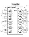
- FIG. 1 is a diagram showing a configuration of a multi-band transmission system using WDM according to an embodiment of the present invention.
- the difference between the multi-band transmission system (system) 10A shown in FIG. 1 and the conventional multi-band transmission system (FIG. 6) is that the wavelength cross-connect devices 20aA, 20bA, 20cA, 20dA, 20eA, and 20fA have different bands. It is possible to transmit an optical signal through the WDM network Sn, Cn, and Ln.
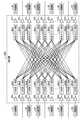
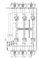
- FIG. 2 shows the configuration of the wavelength cross-connect device 20A used in the system 10A of the present embodiment.
- the wavelength cross-connect device 20A shows the wavelength cross-connect devices 20aA to 20fA having the same configuration.
- the wavelength cross-connect device 20A has an S / C conversion unit 31 and an L / C conversion unit 32 on the input side, and an optical amplifier 24a to 24m between the demultiplexer 11a to 11m and the duplexer 12a to 12m (FIG. It is configured to include one WXC unit 22A (not shown in FIG. 2), optical amplifiers 27a to 27m on the output side (not shown in FIG. 2), a C / S conversion unit 35, and a C / L conversion unit 36. .. Further, a link wavelength allocation control unit 29 is connected to the wavelength cross-connect device 20A. However, as shown in FIG. 1, the link wavelength allocation control unit 29 is connected to a state in which all wavelength cross-connect devices 20a to 20f of the system 10A are collectively controlled.
- the link wavelength allocation control unit 29 may be configured as one device.
- the WXC unit 22A handles wavelengths in a specific wavelength band, for example, the C band.
- the WXC unit 22A is a set of m sets of optical amplifiers 24a, 24b, ..., 24m having three sets on the input side, and 1 ⁇ W (M-1) connected to each of these optical amplifiers 24a to 24m.
- WSS25a1 to 25a3, 25b1 to 25b3, ..., 25m1 to 25m3 also referred to as WSS25a1 to 25m3.
- W (M-1) On the output side of the WXC unit 22A, there are the same number of W (M-1) ⁇ 1 WSS26a1 to 26a3, 26b1 to 26b3 ... And M sets of optical amplifiers 27a, 27b, ..., 27m, each of which is a set of three.
- W (M-1) indicates that each WSS25a1 to 25m3 has one input end.
- W (M-1) indicates the number of branches at the output end of each WSS25a1 to 25m3. Further, in W (M-1) ⁇ 1, “W (M-1)” indicates the number of branches on the input side of each WSS26a1 to 26m3. “1" indicates that each WSS26a1 to 26m3 has one output end.
- W indicates the number of wavelength bands, and in this example, it is assumed that there are three wavelength bands of S band, C band and L band.
- M indicates the number of sets when the same number of WSS26a1 to 26m3 and WSS26a1 to 26m3 are grouped in the same direction.
- the output ends of WSS25a1 in the first set from the top are WSS26b1A to 26b3 of the second set other than the own way, that is, the second set other than the first set, and the mth set (for example). It is connected to a total of 6 output ends with WSS26m1A to 26m3 in the direction of (the third set).
- WSS25a1 on the input side and WSS26b1 on the output side output multiple branches of input from one input end on the input side from one output end, and then output multiple composite inputs from one input end on the output side to one output end.
- the optical signal output from is being processed. Since other WSSs have the same connection mode, the description thereof will be omitted.
- the link wavelength allocation control unit 29 includes a wavelength allocation table (wavelength allocation tables 9ef, 9fa as an example), and S band and C band connecting the wavelength cross-connect devices 20a to 20f. And, the optical path (link) is assigned to each WDM network Sn to Ln in the L band, and the wavelength allocation table is set to allocate the predetermined wavelengths ⁇ 1 to ⁇ 96.
- a wavelength allocation table wavelength allocation tables 9ef, 9fa as an example
- the wavelength allocation table 9ef is set to allocate wavelengths ⁇ 1 to ⁇ 96 to any of the S band, C band, and L band optical paths between the wavelength cross-connect devices 20eA and 20fA.
- the wavelength allocation table 9fa is set to allocate wavelengths ⁇ 1 to ⁇ 96 to any of the S band, C band, and L band optical paths between the wavelength cross-connect devices 20fA and 20aA.
- the link wavelength allocation control unit 29 is set to allocate the wavelength ⁇ 1 to the L-band WDM network Ln and the C-band WDM network Cn between the wavelength cross-connect devices 20eA and 20fA in the wavelength allocation table 9ef. It is carried out. Further, in the wavelength allocation table 9fa, the wavelength ⁇ 1 is assigned to the WDM network Ln in the L band between the wavelength cross-connect devices 20fA and 20aA.
- the link wavelength allocation control unit 29 is on the L-band WDM network Ln from, for example, the wavelength cross-connect device 20dA, 20eA, 20fA from the input side route Mi1 toward the output side route Mo1.
- An optical path P1 solid line capable of transmitting an optical signal ⁇ 1L having a wavelength ⁇ 1 in the L band can be established.
- the link wavelength allocation control unit 29 moves from the input side direction Mi2 toward the output side direction Mo2 via the wavelength cross-connect devices 20eA, 20fA, 20aA, and between the wavelength cross-connect devices 20eA, 20fA.
- An optical path P2a (broken line) capable of transmitting the same optical signal ⁇ 1L as described above can be set on the C-band WDM network Cn and on the L-band WDM network Ln between the wavelength cross-connect devices 20fA and 20aA. ..
- the link wavelength division control unit 29 extends different optical paths P1 and P2a in which the optical signal ⁇ 1L of the same wavelength ⁇ 1 is transmitted in the same section (for example, between the wavelength cross-connect devices 20eA and 20fA), these optical paths P1 and P2a are spread over WDM networks (C band WDM network Cn and L band WDM network Ln) in different bands in the same section.
- WDM networks C band WDM network Cn and L band WDM network Ln
- the allocation of the wavelength ⁇ 1 to each of the WDM networks Cn and Ln of the wavelength allocation tables 9ef and 9fa is set.
- the S / C conversion unit 31 converts the S band light signal into a C band light signal
- the L / C conversion unit 32 converts the L band light signal into a C band light signal.
- each output end of the duplexer 11a to 11m (FIG. 2) and the input end of the WXC unit 22A is as follows. That is, an output in which the wavelength division multiplexing signal light 1a of the S band, C band, and L band transmitted in multiple bands from the input side road Mi (FIG. 2) outputs an S band optical signal demultiplexed by the demultiplexer 11a.
- the end is connected to the optical amplifier 24a of the WXC unit 22A via the S / C conversion unit 31.
- the output end of the C-band optical signal of the duplexer 11a is directly connected to the input end of the optical amplifier 24a of the WXC unit 22A.
- the output end of the L band optical signal of the demultiplexer 11a is connected to the input end of the optical amplifier 24a of the WXC unit 22A via the L / C conversion unit 32.
- the output end of the wavelength division multiplexing signal light 1b from the input side path to output the S band optical signal demultiplexed by the demultiplexer 11b is the optical amplifier 24b of the WXC unit 22A via the S / C conversion unit 31. It is connected to the. Further, the output end of the C-band optical signal of the duplexer 11a is directly connected to the input end of the optical amplifier 24b of the WXC unit 22A. Further, the output end of the L band optical signal of the demultiplexer 11a is connected to the input end of the optical amplifier 24b of the WXC unit 22A via the L / C conversion unit 32.
- the output end of the wavelength division multiplexing signal light 1 m from the input side path to output the S band optical signal demultiplexed by the demultiplexer 11 m is the optical amplifier 24 m of the WXC unit 22A via the S / C conversion unit 31. It is connected to the. Further, the output end of the C-band optical signal of the demultiplexer 11 m is directly connected to the input end of the optical amplifier 24 m of the WXC unit 22A. Further, the output end of the L band optical signal of the demultiplexer 11 m is connected to the input end of the optical amplifier 24 m of the WXC unit 22A via the L / C conversion unit 32.
- the C / S conversion unit 35 connected to the optical amplifiers 27a to 27m on the output side of the WXC unit 22A converts the C band optical signal into which the S band optical signal is converted by the S / C conversion unit 31 on the input side. , Converted to S-band optical signal.
- the C / L conversion unit 36 connected to the optical amplifiers 27a to 27m converts the C-band optical signal converted by the L / C conversion unit 32 on the input side into an L-band optical signal.
- a C / L conversion unit 36 is provided.
- the C / S conversion unit 35 and the C / L conversion unit 36 constitute the output-side conversion unit according to claim.
- the output end for outputting the C band optical signal directly input from the input end is directly connected to the input end of the combiner 12a to 12m.
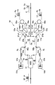
- FIG. 4 shows the circuit configuration of the L / C conversion unit 32 as a representative, and a description thereof will be given.
- the L / C conversion unit 32 shown in FIG. 4 includes a WSS 51, wavelength variable light sources 52a, 52b, amplifiers 53a, 53b, polarization controllers 54a, 54b, and WDM (Wavelength Division Multiplexing) couplers 55a, 55b, 56a, It is configured to include a 56b, a polarization beam splitters 57a and 57b, a polarization controller 58a and 58b, a loop-shaped highly nonlinear fiber 59a and 59b, and an optical coupler 60.
- WSS 51 wavelength variable light sources 52a, 52b, amplifiers 53a, 53b, polarization controllers 54a, 54b, and WDM (Wavelength Division Multiplexing) couplers 55a, 55b, 56a
- WDM Widelength Division Multiplexing
- a indicates a component on the long wavelength side of the optical signal
- b indicates a component on the short wavelength side of the optical signal
- the polarization beam splitter 57a connects two input / output ports 57a1 and 57a2 in a loop shape with an optical fiber, and a loop-shaped high non-linear fiber 59a is connected in the middle of the optical fiber. Further, a polarization controller 58a is connected between one input / output port 57a1 of the polarization beam splitter 57a and the highly non-linear fiber 59a.
- two input / output ports 57b1 and 57b2 are connected by an optical fiber in a loop shape, and a loop-shaped high nonlinear fiber 59b is connected in the middle of the optical fiber.
- a polarization controller 58b is connected between one input / output port 57b1 of the polarization beam splitter 57b and the highly nonlinear fiber 59b.
- the pump light output from the wavelength-variable light source 52a is amplified by the amplifier 53a, and the pump light Pa whose polarization is controlled by the polarization controller 54a is input to the polarization beam splitter 57a via the WDM couplers 55a and 56a.
- the pump light Pa is input to the polarization beam splitter 57a in a linearly polarized state tilted by 45 degrees with respect to the main axis of the polarization beam splitter 57a.
- the tilt of 45 degrees is realized by the polarization control of the polarization controller 54a.
- the pump light output from the wavelength variable light source 52b is amplified by the amplifier 53b, and the pump light Pb whose polarization is controlled by the polarization controller 54b is input to the polarization beam splitter 57b via the WDM couplers 55b and 56b. ..
- the pump light Pb is input to the polarization beam splitter 57b in a linearly polarized state tilted by 45 degrees with respect to the main axis of the polarization beam splitter 57b.
- the tilt of 45 degrees is realized by the polarization control of the polarization controller 54b.
- the L band optical signal (also referred to as optical signal L) is input from the demultiplexer 11a shown in FIG. 1 to the WSS 51 shown in FIG. 4 of the L / C conversion unit 32.
- this optical signal L an optical signal of the long wavelength side La (also referred to as a long wavelength side optical signal La) and an optical signal of the short wavelength side Lb (also referred to as a short wavelength side optical signal Lb) are combined.
- the WSS 51 divides the optical signal L into a long wavelength side optical signal La and a short wavelength side optical signal Lb and outputs the optical signal L.
- This long wavelength side optical signal La is input to the polarization beam splitter 57a via the WDM couplers 55a and 56a.
- the short wavelength side optical signal Lb is input to the polarization beam splitter 57b via the WDM couplers 55b and 56b.
- the long wavelength side optical signal La and the pump light Pa input to the polarization beam splitter 57a are output from the first input / output port 57a1 of the polarization beam splitter 57a, and are indicated by the arrow Y5a. As shown, it follows a loop path input to the second input / output port 57a2 via the polarization controller 58a and the highly nonlinear fiber 59a.
- the long wavelength side optical signal La and the pump optical Pa output from the first input / output port 57a1 of the polarization beam splitter 57a are controlled by the polarization controller 58a and are controlled by the highly nonlinear fiber 59a.
- the highly non-linear fiber 59a is an optical fiber having a high non-linear constant as a parameter, and efficiently causes four-wave mixing in a loop to perform wavelength band conversion.
- the highly non-linear fiber 59a is a new one wavelength band by interacting two wavelength bands of the long wavelength side optical signal La and the pump light Pa as a non-linear optical intermodulation phenomenon by the four-wave mixing process.
- An optical signal Ca on the long wavelength side of the C band is generated.
- the generated optical signal Ca, the long wavelength side optical signal La, and the pump optical Pa are input to the second input / output port 57a2 of the polarization beam splitter 57a.
- the long wavelength side optical signal La and the pump optical Pa input to the polarization beam splitter 57a are output from the second input / output port 57a2 and are high as shown by the arrow Y6a in the direction opposite to the arrow Y5a. It follows a loop path input to the first input / output port 57a1 via the non-linear fiber 59a and the polarization controller 58a. In this loop path as well, a new optical signal (also referred to as a long wavelength side optical signal Ca) of the C band long wavelength side Ca is newly generated by the four-wave mixing process.
- a new optical signal also referred to as a long wavelength side optical signal Ca
- the two long wavelength side optical signals Ca generated by following the loop path in both directions are wavelength-multiplexed by the polarization beam splitter 57a. As shown by the arrow Y7a, this long wavelength side optical signal Ca is output toward the input side, extracted by the WDM coupler 56a, and output to the optical coupler 60.
- the same wavelength band conversion process as on the long wavelength side is performed. That is, the long wavelength side optical signal Lb and the pump light Pb input to the polarization beam splitter 57b are output from the first input / output port 57b1 of the polarization beam splitter 57b, and as shown by the arrow Y5b, the polarization controller 58b. And follow the loop path input to the second input / output port 57b2 via the highly non-linear fiber 59b.
- the long wavelength side optical signal Lb and the pump light Pb output from the first input / output port 57b1 are subjected to four-wave mixing processing by the highly nonlinear fiber 59b while the polarization is controlled by the polarization controller 58b. ..
- a new optical signal Cb on the short wavelength side of the C band is newly generated, and is input to the second input / output port 57b2 of the polarization beam splitter 57b together with the long wavelength side optical signal Lb and the pump light Pb.
- the long wavelength side optical signal Lb and the pump light Pb follow the loop path indicated by the arrow Y6b in the direction opposite to the arrow Y5b from the second input / output port 57b2 of the polarization beam splitter 57b.
- a new optical signal on the short wavelength side Cb in the C band (also referred to as a short wavelength side optical signal Cb) is newly generated by the four-wave mixing process in the same manner as described above.
- the two short wavelength side optical signals Cb generated by following the loop path in both directions are wavelength-multiplexed by the polarization beam splitter 57b, output to the input side indicated by the arrow Y7b, and are optical couplers via the WDM coupler 56b. It is output to 60.
- the optical coupler 60 combines the long wavelength side optical signal Ca and the short wavelength side optical signal Cb to form a C band optical signal.
- the L / C conversion unit 32 converts the L-band optical signal from the demultiplexer 11a into a C-band optical signal. This converted C-band optical signal is input to the optical amplifier 24a of the WXC unit 22A.
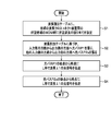
- step S1 shown in FIG. 5, as shown in FIG. 1, the link wavelength allocation control unit 29 displays the wavelength allocation table 9ef in the L-band WDM network Ln and the C-band WDM network Cn between the wavelength cross-connect devices 20eA and 20fA. It is assumed that the wavelength ⁇ 1 is assigned to. Further, it is assumed that the link wavelength allocation control unit 29 assigns the wavelength ⁇ 1 to the wavelength allocation table 9fa and the WDM network Ln in the L band between the wavelength cross-connect devices 20fA and 20aA.
- step S2 the link wavelength allocation control unit 29 transfers the L from the input side route Mi1 to the output side route Mo1 via the wavelength cross-connect devices 20d, 20e, 20f based on the wavelength allocation table 9ef.
- An optical path P1 (solid line) is laid on the WDM network Ln of the band.
- the link wavelength division control unit 29 moves from the input side direction Mi2 to the output side direction Mo2 via the wavelength cross-connect devices 20eA, 20fA, 20aA based on the wavelength allocation tables 9ef and 9fa, and wavelength crossing.
- An optical path P2a (1L) capable of transmitting the same optical signal ⁇ 1L as above on the C-band WDM network Cn between the connect devices 20eA and 20fA and on the L-band WDM network Ln between the wavelength cross-connect devices 20fA and 20fA ( Draw a broken line).
- different optical paths P1 and P2a through which the optical signal ⁇ 1L of the same wavelength ⁇ 1 is transmitted are stretched in the same section (between the wavelength cross-connect devices 20eA and 20fA), so that the optical paths P1 and P2a are different in the same section. It will be stretched over the WDM network of the band (WDM network Cn of the C band and WDM network Ln of the L band).
- step S3 an optical signal ⁇ 1L having a wavelength ⁇ 1 in the L band is transmitted from the direction Mi1 on the input side to the optical path P1 as follows.
- the L-band optical signal ⁇ 1L input from the input-side direction Mi1 to the wavelength cross-connect device 20dA is converted into the C-band by the L / C conversion unit 32 via, for example, the demultiplexer 11a shown in FIG. To.
- the converted C-band optical signal ⁇ 1L is input to the WSS25a3 via the optical amplifier 24a of the WXC unit 22A shown in FIG. 3, and is output from this output end to, for example, the L-band series WSS26b3.
- the C-band optical signal ⁇ 1L is converted from the WSS26b3 to the L-band by the C / L conversion unit 36 via the optical amplifier 27b, and is converted into the L-band from the WSS26b3 via the optical path P1 on the WDM network Ln of the L-band shown in FIG. It is input to the wavelength cross-connect device 20eA of.
- the wavelength cross-connect device 20eA also performs the same processing as the wavelength cross-connect device 20dA in the previous stage, and the wavelength cross-connect device 20fA in the subsequent stage also performs the same processing.
- the optical signal ⁇ 1L having a wavelength ⁇ 1 in the L band is output from, for example, the combiner 12b shown in FIG. 2 to the output-side direction Mo1 (FIG. 1).
- step S4 an optical signal ⁇ 1L having a wavelength ⁇ 1 is transmitted from the direction Mi2 shown in FIG. 1 to the optical path P2a in the same L band as above as follows.
- the L-band optical signal ⁇ 1L input from the input-side direction Mi2 to the wavelength cross-connect device 20eA is converted into the C-band by the L / C conversion unit 32 via, for example, the demultiplexer 11a shown in FIG. To.
- the converted C-band optical signal ⁇ 1L is input to the WSS25a3 via the optical amplifier 24a shown in FIG. 3, and is output from this output end to, for example, the C-band series WSS26b2.
- the C-band optical signal ⁇ 1L is input from the WSS26b2 to the wavelength cross-connect device 20fA in the subsequent stage via the optical amplifier 27b and the optical path P2a on the C-band WDM network Cn shown in FIG.
- the C-band optical signal ⁇ 1L input to the wavelength cross-connect device 20fA is input to WSS25b2 via the optical amplifier 24b shown in FIG. 3, and is output from this output end to, for example, WSS26a3 in the L-band series.
- the C-band optical signal ⁇ 1L is converted from the WSS26b3 to the L-band by the C / L conversion unit 36 via the optical amplifier 27b, and further later via the optical path P2a on the L-band WDM network Ln shown in FIG. It is input to the wavelength cross-connect device 20aA of.
- the optical signal ⁇ 1L in the L band is converted into the C band by the L / C conversion unit 32 via, for example, the demultiplexer 11a shown in FIG.
- the C-band optical signal ⁇ 1L is input to WSS25a3 via the optical amplifier 24a shown in FIG. 3, and is output from this output end to, for example, WSS26b3 in the L-band series.
- the C-band optical signal ⁇ 1L is converted from the WSS26b3 to the L-band by the C / L conversion unit 36 via the optical amplifier 27b, and the direction Mo2 on the output side from the combiner 12b shown in FIG. 2 (FIG. 1). Is output to.
- the wavelength cross-connect devices 20A (wavelength cross-connect devices 20aA to 20fA) of the multi-band transmission system 10A of the present embodiment are different and plural, which have been multi-band transmitted by an optical transmission line composed of one or a plurality of optical fibers.
- the wavelength-multiplexed signal light obtained by multiplexing each optical signal of each wavelength band of the above wavelength band amplified the optical signal of each wavelength band divided into different wavelength bands for each direction Mi by optical amplifiers 24a to 24m and 27a to 27m. After that, the direction is changed at WSS25a1 to 25m3 and 26a1 to 26m3, and relay processing is performed to output to the output side direction Mo.
- WSS25a1 to 25m3 and 26a1 to 26m3 perform optical signal processing in which an input from one input end is output from one output end in multiple branches on the input side, and then a plurality of combined inputs from one input end are output from one output end on the output side. Is going.
- the wavelength cross-connect device 20A has optical amplifiers 24a to 24m, 27a to 27m and WSS25a1 to 25m3,26a1 to 26m3, and is predetermined among different wavelength bands (wavelength bands of S band, C band and L band).
- the WXC unit 22A that relays the optical signal of the specific wavelength band (C band) is provided. Further, on the input side of the WXC unit 22A, an input side conversion unit (S / C conversion unit 31 and an L / C conversion unit 32) that converts an optical signal in a wavelength band other than the specific wavelength band into an optical signal in the specific wavelength band. ).
- the output side conversion unit (C / S conversion unit 35 and C / L conversion) that converts the optical signal of the specific wavelength band converted by the input side conversion unit into the optical signal before conversion.
- a unit 36 is provided on the output side of the WXC unit 22A.
- one WXC unit 22A after converting optical signals of different wavelength bands into optical signals of the same wavelength band (specific wavelength band), one WXC unit 22A can perform optical signal processing in the specific wavelength band. Therefore, the device scale and power consumption of the WXC unit 22A can be reduced.
- the multi-band transmission system 10A includes a plurality of wavelength cross-connect devices 20A according to the above (1), and a plurality of wavelength cross-connect devices 20aA to 20fA on the input / output side of the wavelength cross-connect devices 20aA to 20fA. It is configured by connecting a plurality of bands in a ring shape with WDM networks Sn to Ln.
- a predetermined wavelength ⁇ 1 is assigned to the WDM networks Cn and Ln for each of a plurality of bands (C band and L band) between wavelength cross-connect devices (for example, wavelength cross-connect devices 20eA and 20fA) connected in a ring shape, and this is assigned.
- the allocation control unit 29 is provided.
- the link wavelength division control unit 29 sets different optical paths P1 and P2a in which optical signals of the same wavelength ⁇ 1 are transmitted in the same section between the wavelength cross-connect devices 20eA and 20fA in different bands (C band and L band) in the same section. ) WDM network Cn, Ln is controlled to be stretched.
- a wavelength cross-connect device wherein the wavelength cross-connect device transmits each optical signal of a plurality of different wavelength bands transmitted in multiple bands by an optical transmission line composed of one or a plurality of optical fibers. Multiplexed wavelengths Multiple signal light is divided into different wavelength bands for each direction. After amplifying the optical signal of each wavelength band with an optical amplifier, the input from one input end is input from one output end on the input side. After multiple branch output, the WSS, which performs optical signal processing to output multiple composite inputs from one output end on the output side, changes the direction and performs relay processing to output to the output side direction.
- WXC Widelength Cross Connect
- An input side conversion unit that converts an optical signal in a wavelength band other than the specific wavelength band into an optical signal in the specific wavelength band is provided, and a specific wavelength converted by the input side conversion unit is provided on the output side of the WXC unit.
- An output side conversion unit that converts an optical signal in a band into an optical signal before conversion is provided, and an optical signal in the specific wavelength band directly input from the input side is directly output after relay processing in the WXC unit. It is a wavelength cross-connect device characterized by the above.
- optical signal processing can be performed in the specific wavelength band by one WXC unit. Therefore, the device scale and power consumption of the WXC unit can be reduced.
- a plurality of wavelength cross-connect devices according to (1) above are provided, and a plurality of wavelength cross-connect devices are ringed by a WDM (Wavelength Division Multiplex) network for each of a plurality of bands on the input / output side of the wavelength cross-connect device.
- It is a multi-band transmission system configured by connecting in a shape, and a predetermined wavelength is assigned to a WDM network for each of a plurality of bands between the wavelength cross-connect devices connected in a ring shape, and the light having the assigned wavelength is assigned.
- the link wavelength allocation control unit is provided for controlling the optical path through which a signal is transmitted between the input side route and the output side route via one or a plurality of wavelength cross-connect devices, and the link wavelength allocation control unit is provided.
- the unit is a multi-band transmission system characterized in that different optical paths through which optical signals of the same wavelength are transmitted are stretched over a WDM network of different bands in the same section in the same section between wavelength cross-connect devices. be.
Landscapes
- Engineering & Computer Science (AREA)
- Computer Networks & Wireless Communication (AREA)
- Signal Processing (AREA)
- Physics & Mathematics (AREA)
- Electromagnetism (AREA)
- Optical Communication System (AREA)
Abstract
Description
<実施形態の構成>
図1は、本発明の実施形態に係るWDMを用いたマルチバンド伝送システムの構成を示す図である。図1に示すマルチバンド伝送システム(システム)10Aが、従来のマルチバンド伝送システム(図6)と異なる点は、各波長クロスコネクト装置20aA,20bA,20cA,20dA,20eA,20fAが、異なる帯域のWDM網Sn,Cn,Ln間を通って光信号を伝送可能としたことにある。
上述したS/C変換部31、L/C変換部32、C/S変換部35及びC/L変換部36の回路構成は、実質上同一構成となっている。このため、図4にL/C変換部32の回路構成を代表して示し、その説明を行う。
即ち、偏波ビームスプリッタ57bに入力された長波長側光信号Lb及びポンプ光Pbは、偏波ビームスプリッタ57bの第1入出力ポート57b1から出力され、矢印Y5bで示すように、偏波コントローラ58b及び高非線形性ファイバ59bを介して第2入出力ポート57b2に入力されるループ経路を辿る。
次に、図1に示すマルチバンド伝送システム10Aの動作を、図5のフローチャートを参照して説明する。
本実施形態のマルチバンド伝送システム10Aの波長クロスコネクト装置20A(波長クロスコネクト装置20aA~20fA)は、1本又は複数本の光ファイバから構成される光伝送路でマルチバンド伝送されてきた異なる複数の波長帯の各光信号を多重化した波長多重信号光が、方路Mi毎に、異なる波長帯に分波された各波長帯の光信号を光アンプ24a~24m,27a~27mで増幅した後、WSS25a1~25m3,26a1~26m3で方路変更し、出力側の方路Moへ出力する中継処理を行っている。
(1)波長クロスコネクト装置であって、前記波長クロスコネクト装置は、1本又は複数本の光ファイバから構成される光伝送路でマルチバンド伝送されてきた異なる複数の波長帯の各光信号を多重化した波長多重信号光が、方路毎に、異なる波長帯に分波された各波長帯の光信号を光アンプで増幅した後、入力側において1入力端からの入力を1出力端から複数分岐出力後に、出力側において1入力端からの複数合成入力を1出力端から出力する光信号処理を行うWSSで方路変更し、出力側の方路へ出力する中継処理を行っており、前記光アンプ及び前記WSSを有し、前記異なる波長帯の内、予め定められた特定波長帯の光信号の前記中継処理を行うWXC(Wavelength Cross Connect)部を備え、前記WXC部の入力側に、前記特定波長帯以外の波長帯の光信号を、当該特定波長帯の光信号に変換する入力側変換部を備え、前記WXC部の出力側に、前記入力側変換部で変換された特定波長帯の光信号を、変換前の光信号に変換する出力側変換部を備え、前記入力側から直接入力された前記特定波長帯の光信号は、前記WXC部での中継処理後に直接出力するようにしたことを特徴とする波長クロスコネクト装置である。
9ef,9fa 波長割当テーブル
10A マルチバンド伝送システム
11a~11m 波長帯分波器
12a~12m 波長帯合波器
20A 波長クロスコネクト装置
22A WXC部
24b~24m,27a~27m 光アンプ
25a1~25m3,26a1~26m3 WSS
29 リンク波長割当制御部
31 S/C変換部(入力側変換部)
32 L/C変換部(入力側変換部)
35 C/S変換部(出力側変換部)
36 C/L変換部(出力側変換部)
Sn S帯のWDM網
Cn C帯のWDM網
Ln L帯のWDM網
Mi 入力側の方路
Mo 出力側の方路
P1,P2a 光パス
λ1L 光信号
Claims (3)
- 波長クロスコネクト装置であって、
前記波長クロスコネクト装置は、1本又は複数本の光ファイバから構成される光伝送路でマルチバンド伝送されてきた異なる複数の波長帯の各光信号を多重化した波長多重信号光が、方路毎に、異なる波長帯に分波された各波長帯の光信号を光アンプで増幅した後、入力側において1入力端からの入力を1出力端から複数分岐出力後に、出力側において1入力端からの複数合成入力を1出力端から出力する光信号処理を行うWSS(Wavelength Selective Switch)で方路変更し、出力側の方路へ出力する中継処理を行っており、
前記光アンプ及び前記WSSを有し、前記異なる波長帯の内、予め定められた特定波長帯の光信号の前記中継処理を行うWXC(Wavelength Cross Connect)部を備え、
前記WXC部の入力側に、前記特定波長帯以外の波長帯の光信号を、当該特定波長帯の光信号に変換する入力側変換部を備え、
前記WXC部の出力側に、前記入力側変換部で変換された特定波長帯の光信号を、変換前の光信号に変換する出力側変換部を備え、
前記入力側から直接入力された前記特定波長帯の光信号は、前記WXC部での中継処理後に直接出力するようにした
ことを特徴とする波長クロスコネクト装置。 - 請求項1に記載の波長クロスコネクト装置を複数備え、複数の波長クロスコネクト装置を、当該波長クロスコネクト装置における入出力側の複数の帯域毎にWDM(Wavelength Division Multiplex)網でリング状に接続して構成されるマルチバンド伝送システムであって、
前記リング状に接続された波長クロスコネクト装置間の複数の帯域毎のWDM網に所定の波長を割り当て、この割り当てられた波長の光信号が伝送される光パスを、1又は複数の波長クロスコネクト装置を介して入力側の方路と出力側の方路間に張る制御を行うリンク波長割当制御部を備え、
前記リンク波長割当制御部は、波長クロスコネクト装置間による同一区間に、同波長の光信号が伝送される異なる光パスを、同一区間の異なる帯域のWDM網に張る制御を行う
ことを特徴とするマルチバンド伝送システム。 - 請求項1に記載の波長クロスコネクト装置を複数備え、複数の波長クロスコネクト装置を、当該波長クロスコネクト装置における入出力側の複数の帯域毎にWDM網でリング状に接続して構成されるマルチバンド伝送システムのマルチバンド伝送方法であって、
前記リング状に接続された波長クロスコネクト装置間の複数の帯域毎のWDM網に所定の波長を割り当て、この割り当てられた波長の光信号が伝送される光パスを、1又は複数の波長クロスコネクト装置を介して入力側の方路と出力側の方路間に張る制御を行うリンク波長割当制御部を、前記マルチバンド伝送システムに備え、
前記リンク波長割当制御部は、
前記波長クロスコネクト装置間による同一区間に、同波長の光信号が伝送される異なる光パスを、同一区間の異なる帯域のWDM網に張るステップ
を実行することを特徴とするマルチバンド伝送方法。
Priority Applications (3)
| Application Number | Priority Date | Filing Date | Title |
|---|---|---|---|
| US18/014,673 US12316383B2 (en) | 2020-07-06 | 2020-07-06 | Wavelength cross connect device, multiband transmission system, and multiband transmission method |
| PCT/JP2020/026498 WO2022009292A1 (ja) | 2020-07-06 | 2020-07-06 | 波長クロスコネクト装置、マルチバンド伝送システム及びマルチバンド伝送方法 |
| JP2022534520A JP7472982B2 (ja) | 2020-07-06 | 2020-07-06 | 波長クロスコネクト装置、マルチバンド伝送システム及びマルチバンド伝送方法 |
Applications Claiming Priority (1)
| Application Number | Priority Date | Filing Date | Title |
|---|---|---|---|
| PCT/JP2020/026498 WO2022009292A1 (ja) | 2020-07-06 | 2020-07-06 | 波長クロスコネクト装置、マルチバンド伝送システム及びマルチバンド伝送方法 |
Publications (1)
| Publication Number | Publication Date |
|---|---|
| WO2022009292A1 true WO2022009292A1 (ja) | 2022-01-13 |
Family
ID=79552295
Family Applications (1)
| Application Number | Title | Priority Date | Filing Date |
|---|---|---|---|
| PCT/JP2020/026498 Ceased WO2022009292A1 (ja) | 2020-07-06 | 2020-07-06 | 波長クロスコネクト装置、マルチバンド伝送システム及びマルチバンド伝送方法 |
Country Status (3)
| Country | Link |
|---|---|
| US (1) | US12316383B2 (ja) |
| JP (1) | JP7472982B2 (ja) |
| WO (1) | WO2022009292A1 (ja) |
Cited By (1)
| Publication number | Priority date | Publication date | Assignee | Title |
|---|---|---|---|---|
| JPWO2023199397A1 (ja) * | 2022-04-12 | 2023-10-19 |
Families Citing this family (2)
| Publication number | Priority date | Publication date | Assignee | Title |
|---|---|---|---|---|
| JP7694655B2 (ja) * | 2021-06-07 | 2025-06-18 | 日本電信電話株式会社 | 波長クロスコネクト装置及び波長クロスコネクト方法 |
| WO2025253451A1 (ja) * | 2024-06-03 | 2025-12-11 | Ntt株式会社 | 情報処理装置、伝送パス設計方法、及びプログラム |
Citations (5)
| Publication number | Priority date | Publication date | Assignee | Title |
|---|---|---|---|---|
| JP2000115133A (ja) * | 1998-10-05 | 2000-04-21 | Fujitsu Ltd | 光パスクロスコネクト装置及び光ネットワーク |
| JP2002101432A (ja) * | 2000-07-21 | 2002-04-05 | Fujitsu Ltd | 光スイッチ網、光クロスコネクト装置および光分岐・挿入装置 |
| JP2003188830A (ja) * | 2001-12-20 | 2003-07-04 | Nikon Corp | 波長多重光伝送用装置、中継装置、分配装置及び波長多重光伝送システム |
| JP2004254157A (ja) * | 2003-02-21 | 2004-09-09 | Fujitsu Ltd | 光クロスコネクト装置 |
| JP2020137042A (ja) * | 2019-02-25 | 2020-08-31 | 富士通株式会社 | 伝送装置及び伝送システム |
Family Cites Families (1)
| Publication number | Priority date | Publication date | Assignee | Title |
|---|---|---|---|---|
| US20150256908A1 (en) * | 2014-03-05 | 2015-09-10 | Oplink Communications, Inc. | N-degree cdc wsx roadm |
-
2020
- 2020-07-06 JP JP2022534520A patent/JP7472982B2/ja active Active
- 2020-07-06 US US18/014,673 patent/US12316383B2/en active Active
- 2020-07-06 WO PCT/JP2020/026498 patent/WO2022009292A1/ja not_active Ceased
Patent Citations (5)
| Publication number | Priority date | Publication date | Assignee | Title |
|---|---|---|---|---|
| JP2000115133A (ja) * | 1998-10-05 | 2000-04-21 | Fujitsu Ltd | 光パスクロスコネクト装置及び光ネットワーク |
| JP2002101432A (ja) * | 2000-07-21 | 2002-04-05 | Fujitsu Ltd | 光スイッチ網、光クロスコネクト装置および光分岐・挿入装置 |
| JP2003188830A (ja) * | 2001-12-20 | 2003-07-04 | Nikon Corp | 波長多重光伝送用装置、中継装置、分配装置及び波長多重光伝送システム |
| JP2004254157A (ja) * | 2003-02-21 | 2004-09-09 | Fujitsu Ltd | 光クロスコネクト装置 |
| JP2020137042A (ja) * | 2019-02-25 | 2020-08-31 | 富士通株式会社 | 伝送装置及び伝送システム |
Cited By (3)
| Publication number | Priority date | Publication date | Assignee | Title |
|---|---|---|---|---|
| JPWO2023199397A1 (ja) * | 2022-04-12 | 2023-10-19 | ||
| WO2023199397A1 (ja) * | 2022-04-12 | 2023-10-19 | 日本電信電話株式会社 | 波長クロスコネクト装置、および、波長クロスコネクト方法 |
| JP7786567B2 (ja) | 2022-04-12 | 2025-12-16 | Ntt株式会社 | 波長クロスコネクト装置、および、波長クロスコネクト方法 |
Also Published As
| Publication number | Publication date |
|---|---|
| US12316383B2 (en) | 2025-05-27 |
| JPWO2022009292A1 (ja) | 2022-01-13 |
| JP7472982B2 (ja) | 2024-04-23 |
| US20230275668A1 (en) | 2023-08-31 |
Similar Documents
| Publication | Publication Date | Title |
|---|---|---|
| US6271949B1 (en) | Optical communication system using wavelength-division multiplexed light | |
| JP2006140598A (ja) | 光伝送装置及び同装置の経路増設方法並びに同装置の経路増設用光スイッチモジュール | |
| SE469149B (sv) | Optisk vaeljare, optisk korskopplare och saett att omkoppla grupper av optiska signaler | |
| JP7472982B2 (ja) | 波長クロスコネクト装置、マルチバンド伝送システム及びマルチバンド伝送方法 | |
| JP7544124B2 (ja) | 波長クロスコネクト装置及び波長クロスコネクト方法 | |
| JP2020137042A (ja) | 伝送装置及び伝送システム | |
| JP4152932B2 (ja) | 光分波方法および光合波方法、並びに、それを用いた光伝送装置 | |
| US20230224060A1 (en) | Apparatus and Method for Coherent Optical Multiplexing 1+1 Protection | |
| JP4344614B2 (ja) | 光通信ネットワークにおけるノイズ削減 | |
| WO2022259320A1 (ja) | 波長クロスコネクト装置及び波長クロスコネクト方法 | |
| WO2023042396A1 (ja) | 光伝送装置及び通信方法 | |
| US10972188B2 (en) | Transmission apparatus and transmission method | |
| JPWO2022009292A5 (ja) | ||
| JP7694655B2 (ja) | 波長クロスコネクト装置及び波長クロスコネクト方法 | |
| WO2020189386A1 (ja) | 光分岐挿入装置及び光分岐挿入方法 | |
| JP2023067127A (ja) | 光信号処理装置 | |
| JP6523218B2 (ja) | 可変光分岐装置 | |
| JP7294461B2 (ja) | 波長クロスコネクト装置及び波長クロスコネクト方法 | |
| WO2022259318A1 (ja) | 波長クロスコネクト装置及び波長クロスコネクト方法 | |
| WO2024161646A1 (ja) | 通信装置、光アドドロップ装置、および信号処理方法 | |
| WO2024053016A1 (ja) | 通信システム、および制御方法 | |
| WO2022259321A1 (ja) | 波長クロスコネクト装置及び波長クロスコネクト方法 | |
| WO2020049791A1 (ja) | 光伝送装置、光通信システム及び光信号の伝送方法 | |
| JP4872717B2 (ja) | 光ノード、および光ノードの制御方法 | |
| JP2000165353A (ja) | 波長多重光送信装置とこの装置を備えた波長多重光伝送装置 |
Legal Events
| Date | Code | Title | Description |
|---|---|---|---|
| 121 | Ep: the epo has been informed by wipo that ep was designated in this application |
Ref document number: 20944161 Country of ref document: EP Kind code of ref document: A1 |
|
| ENP | Entry into the national phase |
Ref document number: 2022534520 Country of ref document: JP Kind code of ref document: A |
|
| NENP | Non-entry into the national phase |
Ref country code: DE |
|
| 122 | Ep: pct application non-entry in european phase |
Ref document number: 20944161 Country of ref document: EP Kind code of ref document: A1 |
|
| WWG | Wipo information: grant in national office |
Ref document number: 18014673 Country of ref document: US |