WO2022009252A1 - 緊急通報システム、緊急通報方法、及びプログラム - Google Patents
緊急通報システム、緊急通報方法、及びプログラム Download PDFInfo
- Publication number
- WO2022009252A1 WO2022009252A1 PCT/JP2020/026338 JP2020026338W WO2022009252A1 WO 2022009252 A1 WO2022009252 A1 WO 2022009252A1 JP 2020026338 W JP2020026338 W JP 2020026338W WO 2022009252 A1 WO2022009252 A1 WO 2022009252A1
- Authority
- WO
- WIPO (PCT)
- Prior art keywords
- emergency call
- emergency
- agency
- control device
- receiving table
- Prior art date
- Legal status (The legal status is an assumption and is not a legal conclusion. Google has not performed a legal analysis and makes no representation as to the accuracy of the status listed.)
- Ceased
Links
Images



Classifications
-
- H—ELECTRICITY
- H04—ELECTRIC COMMUNICATION TECHNIQUE
- H04M—TELEPHONIC COMMUNICATION
- H04M3/00—Automatic or semi-automatic exchanges
- H04M3/42—Systems providing special services or facilities to subscribers
- H04M3/50—Centralised arrangements for answering calls; Centralised arrangements for recording messages for absent or busy subscribers ; Centralised arrangements for recording messages
- H04M3/51—Centralised call answering arrangements requiring operator intervention, e.g. call or contact centers for telemarketing
- H04M3/5116—Centralised call answering arrangements requiring operator intervention, e.g. call or contact centers for telemarketing for emergency applications
-
- H—ELECTRICITY
- H04—ELECTRIC COMMUNICATION TECHNIQUE
- H04L—TRANSMISSION OF DIGITAL INFORMATION, e.g. TELEGRAPHIC COMMUNICATION
- H04L65/00—Network arrangements, protocols or services for supporting real-time applications in data packet communication
- H04L65/1066—Session management
- H04L65/1069—Session establishment or de-establishment
-
- H—ELECTRICITY
- H04—ELECTRIC COMMUNICATION TECHNIQUE
- H04L—TRANSMISSION OF DIGITAL INFORMATION, e.g. TELEGRAPHIC COMMUNICATION
- H04L65/00—Network arrangements, protocols or services for supporting real-time applications in data packet communication
- H04L65/1066—Session management
- H04L65/1073—Registration or de-registration
-
- H—ELECTRICITY
- H04—ELECTRIC COMMUNICATION TECHNIQUE
- H04M—TELEPHONIC COMMUNICATION
- H04M11/00—Telephonic communication systems specially adapted for combination with other electrical systems
- H04M11/04—Telephonic communication systems specially adapted for combination with other electrical systems with alarm systems, e.g. fire, police or burglar alarm systems
-
- H—ELECTRICITY
- H04—ELECTRIC COMMUNICATION TECHNIQUE
- H04M—TELEPHONIC COMMUNICATION
- H04M3/00—Automatic or semi-automatic exchanges
- H04M3/42—Systems providing special services or facilities to subscribers
- H04M3/42348—Location-based services which utilize the location information of a target
- H04M3/42357—Location-based services which utilize the location information of a target where the information is provided to a monitoring entity such as a potential calling party or a call processing server
-
- H—ELECTRICITY
- H04—ELECTRIC COMMUNICATION TECHNIQUE
- H04L—TRANSMISSION OF DIGITAL INFORMATION, e.g. TELEGRAPHIC COMMUNICATION
- H04L65/00—Network arrangements, protocols or services for supporting real-time applications in data packet communication
- H04L65/1066—Session management
- H04L65/1101—Session protocols
- H04L65/1104—Session initiation protocol [SIP]
-
- H—ELECTRICITY
- H04—ELECTRIC COMMUNICATION TECHNIQUE
- H04M—TELEPHONIC COMMUNICATION
- H04M2242/00—Special services or facilities
- H04M2242/04—Special services or facilities for emergency applications
-
- H—ELECTRICITY
- H04—ELECTRIC COMMUNICATION TECHNIQUE
- H04M—TELEPHONIC COMMUNICATION
- H04M2242/00—Special services or facilities
- H04M2242/06—Lines and connections with preferential service
-
- H—ELECTRICITY
- H04—ELECTRIC COMMUNICATION TECHNIQUE
- H04M—TELEPHONIC COMMUNICATION
- H04M2242/00—Special services or facilities
- H04M2242/30—Determination of the location of a subscriber
Definitions
- the present invention relates to an emergency call system, an emergency call method, and a program.
- Emergency calls from users who use the network are transmitted as emergency calls to the emergency call reception desk (emergency organization) corresponding to the calling area.
- An emergency call from a user is called by an emergency special number such as 110 to 119, and the emergency call reception desk (hereinafter referred to as the reception desk) corresponding to the calling area is received by the function of the network side.
- Each regional receiving table is assigned a unique telephone number, and the network side identifies the receiving table by the unique telephone number and controls the connection route. It should be noted that even if the user makes a call (call) to the telephone number peculiar to the receiving table on the network side, the network side is controlled so that the incoming call cannot be received on the receiving table.
- the emergency special number (emergency call) is given a special emergency call priority flag in the network and is treated specially (Non-Patent Document 1).
- the emergency call agent has a regional base somewhere, and if you make an emergency call (call at 110 or 119) with an emergency special number from there, just like a normal user, the reception desk of the emergency call agent's regional base The call will not be received at the reception desk in the area where the user who used the emergency call agency is located. Therefore, the emergency call agent must make a call to the reception desk in the area where the user of the emergency call agent is located.
- the emergency call agent responds by setting an emergency call flag.
- the emergency call priority flag and the emergency call flag which indicate that the connection is controlled with priority over the normal user's call and the band for emergency call can be used, are not distinguished. It is not possible to distinguish between an emergency call from a general user and an emergency call from an emergency call agent. Therefore, emergency calls from emergency call agents were prevented from connecting to emergency institutions within the network. That is, there is a problem that the emergency call from the emergency call agent is not connected to the emergency organization.
- the present invention has been made in view of this problem, and an object of the present invention is to provide an emergency call system, an emergency call method, and a program capable of connecting an emergency call from an emergency call agent to an emergency organization. ..
- the emergency call system is an emergency call system including an emergency call control device for notifying an emergency organization of an emergency call from an emergency call agency and a receiving table for receiving the emergency call.
- the emergency call control device includes a registration list in which the emergency call agent is registered, and a filtering unit that transmits only the emergency call from the emergency call agent registered in the registration list to the emergency organization.
- the gist is that the receiving table receives the emergency call transmitted by the filtering unit.
- the emergency call system is an emergency call system including an emergency call control device for notifying an emergency organization of an emergency call from an emergency call agent and a receiving table for receiving the emergency call. Therefore, the emergency call control device generates a hash character string from the user name and password included in the emergency call, sends it to the emergency agency, and acts as an emergency call agent based on the authentication result received from the emergency agency.
- the gist is provided with an authentication control unit that transmits a control signal to a trader
- the receiving table is provided with an authentication unit that receives the hash character string and performs digest authentication of the hash character string.
- the emergency call method is an emergency call method performed by the above-mentioned emergency call system, and the emergency call control device obtains a hash character string from a user name and a password included in the emergency call. Generated and transmitted to the emergency agency, a control signal is transmitted to the emergency call agent based on the authentication result received from the emergency agency, and the receiving table receives the hash character string and the hash character string. The gist is to certify the digest.
- the program according to one aspect of the present invention is a program for operating a computer as the above-mentioned emergency call system.
- an emergency call from an emergency call agent can be connected to an emergency organization.
- FIG. 1 It is a block diagram which shows the functional structure example of the emergency call system which concerns on 1st Embodiment of this invention. It is a figure which shows the operation sequence of the emergency call control device and the receiving table shown in FIG. It is a block diagram which shows the functional structure example of the emergency call system which concerns on 2nd Embodiment of this invention. It is a figure which shows the operation sequence of the emergency call control device and the receiving table shown in FIG. It is a block diagram which shows the configuration example of a general-purpose computer system.
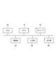
- FIG. 1 is a block diagram showing a functional configuration example of the emergency call system according to the first embodiment of the present invention.
- the emergency call system 100 shown in FIG. 1 is a system for connecting an emergency call to an emergency organization such as police or fire department.
- the emergency call system 100 includes a caller terminal 30, an emergency call agent 40, an emergency call control device 10, and an emergency organization 20. These functional components operate on an IP network. An IP network (not shown) is interposed between each functional component, and SIP (Session Initiation Protocol) is adopted as the communication control protocol.
- SIP Session Initiation Protocol
- FIG. 1 shows only the relationship between the whistleblower terminal 30 possessed by the user who has contracted with the emergency call agency 40 that provides the emergency call service, and the emergency institution 20.
- the emergency call priority flag is given by the terminal accommodating device (not shown) on the calling network side, and the caller's calling area is set. It is connected to the corresponding emergency agency 20, for example.
- the notation of the route is omitted.
- the whistleblower terminal 30 is any of a landline telephone, an information processing device, and a mobile terminal.
- the emergency call agency 40 receives the emergency call transmitted from the whistleblower terminal 30 possessed by the contractor, adds the information on the whereabouts of the whistleblower, and sends it to the emergency agency 20.
- the emergency call agency 40 is, for example, an operator. Alternatively, it may be a server managed by the emergency call agency 40.
- the emergency call control device 10 includes a registration list 11 and a filtering unit 12.
- the registration list 11 is a list in which the emergency call agency 40 is registered.
- the registration list 11 is, for example, a list of telephone numbers of the emergency call agency 40.
- the filtering unit 12 sends only the emergency call from the emergency call agency 40 registered in the registration list 11 to the emergency agency 20.
- an emergency call flag indicating that the call is an emergency call may be added and transmitted.
- the emergency service 20 is provided with a receiving table 21.
- the receiving table 21 receives both an emergency call from the emergency call agency 40 and an emergency call from the emergency call agency 40 and an uncontracted whistleblower terminal (not shown).
- the receiving table 21 is an input / output device (console) that outputs information to the operator engaged in the emergency organization 20 and inputs the information to the operator.
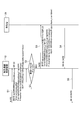
- FIG. 2 is a diagram showing an operation sequence of the emergency call control device 10 and the emergency organization 20 constituting the emergency call system 100. The operation will be described with reference to FIG.
- the emergency call control device 10 receives an emergency call from the emergency call agent 40 (step S1). Emergency calls begin with an INVITE message. To in the header represents the destination of the emergency call. From in the header represents the calling number of the emergency call agency 40.
- the filtering unit 12 determines whether or not the calling number is included in the registration list 11 (step S2). When the calling number is included in the registration list 11, the emergency call starting with the INVITE message is transmitted as it is to the receiving table 21 of the emergency institution 20 (step S3).
- the emergency call control device 10 does not send the emergency call to the receiving table 21. In this case, an error response indicating that the emergency call cannot be sent may be sent to the emergency call agent 40.
- the receiving table 21 provided in the emergency organization 20 returns a response of 200 OK when receiving an emergency call (step S4). Then, the emergency call is dealt with according to a predetermined procedure.
- the emergency call control device 10 transfers the received response of 200 OK to the emergency call agent 40 (step S5).
- the emergency call system 100 includes an emergency call control device 10 for notifying the emergency organization 20 of an emergency call from the emergency call agent 40, and a receiving table 21 for receiving the emergency call.
- the emergency call control device 10 transmits only the registration list 11 in which the emergency call agent 40 is registered and the emergency call from the emergency call agent 40 registered in the registration list 11 to the emergency organization.
- the receiving table 21 is provided with a filtering unit 12, and receives an emergency call transmitted by the filtering unit 12. As a result, the emergency call from the emergency call agent 40 can be connected to the emergency agency 20.
- FIG. 3 is a block diagram showing a functional configuration example of the emergency call system according to the second embodiment of the present invention.
- the emergency call system 200 shown in FIG. 3 differs in that the emergency call control device 13 includes an authentication control unit 14 and the receiving table 23 includes an authentication unit 24.
- the authentication control unit 14 generates a hash character string from the user name and password included in the emergency call and sends it to the receiving table 23, and sends a control signal to the emergency call agent 40 based on the authentication result received from the receiving table 23. Send.
- the authentication unit 24 included in the receiving table 23 receives the hash character string generated by the authentication control unit 14 of the emergency call control device 13 and performs digest authentication of the hash character string.
- FIG. 4 is a diagram showing an operation sequence of the emergency call control device 10 and the emergency organization 22 constituting the emergency call system 200. The operation will be described with reference to FIG.
- the emergency call control device 10 receives an emergency call from the emergency call agent 40 (step S10).
- the emergency call received here differs in that it includes authentication information for digest authentication for the above emergency call.
- the authentication information is the information shown in the two lines starting with Authorization :.
- the authentication control unit 14 generates a hash character string using a user name (bob), a password, a nonce character string (AAAA), a cnonce (BBBB) character string, and the like (step S11).
- the hash character string is transmitted to the emergency agency 22 (step S12).
- the authentication unit 24 provided in the emergency organization 22 performs digest authentication of the received hash character string. Digest authentication calculates the hash value of the correct answer from a random character string (nonce, cnonce) or the like sent from the authentication control unit 14 and a hashed password recorded in advance (step S13), and hashes. It is determined whether or not the values match (step S14).
- the authentication unit 24 transmits the service ID s-id and the auxiliary information ID a-id to the authentication control unit 14 together with the authentication success response 200OK (step S16). If the hash values do not match, an error response is transmitted to the authentication control unit 14 (step S15).
- the authentication control unit 14 controls the emergency call agency 40 based on the received SIP response (200OK, etc.), service ID (s-id), and auxiliary information ID (a-id) (step S17).
- the service ID and auxiliary ID are IDs that control the network on the calling side of the emergency call.
- the service ID is an ID for a network function.
- the auxiliary ID is an ID for controlling the enable / disable of the network function and connecting the guidance.
- the emergency call system 200 includes an emergency call control device 13 for notifying the emergency organization 20 of an emergency call from the emergency call agent 40, and a receiving table 23 for receiving the emergency call.
- the emergency call control device 13 generates a hash character string from the user name and password included in the emergency call, sends it to the emergency institution 22, and makes an emergency based on the authentication result received from the emergency institution 22.
- An authentication control unit 14 that transmits a control signal to the reporting agent 40 is provided, and the receiving table 23 includes an authentication unit 24 that receives a hash character string and digests and authenticates the hash character string.
- the emergency call from the emergency call agent 40 can be connected to the emergency agency 20. Further, by controlling the network on the transmitting side based on the control signals (service ID and auxiliary ID), more detailed control becomes possible.
- the emergency call method performed by the emergency call system 200 is an emergency equipped with an emergency call control device 13 for notifying the emergency organization 22 of an emergency call from the emergency call agent 40 and a receiving table 23 for receiving the emergency call.
- This is an emergency call method performed by the emergency call system, in which the emergency call control device 13 generates a hash character string from the user name and password included in the emergency call and sends it to the emergency agency 22 (step S12, FIG. 4), and makes an emergency.
- a control signal is transmitted to the emergency call agency 40 based on the authentication result received from the institution 22, and the receiving table 23 receives the hash character string and performs digest authentication of the hash character string (step S14, FIG. 4).
- the emergency call systems 100 and 200 can be realized by the general-purpose computer system shown in FIG.
- a general-purpose computer system including a CPU 90, a memory 91, a storage 92, a communication unit 93, an input unit 94, and an output unit 95
- the CPU 90 predicts by executing a predetermined program loaded on the memory 91.
- Each function of the device 100 is realized.
- a given program can be recorded on a computer-readable recording medium such as an HDD, SSD, USB memory, CD-ROM, DVD-ROM, MO, or distributed over a network.
- the present invention is not limited to the above embodiment, and can be modified within the scope of the gist thereof.
- the registration list 11 has been described as recording the telephone number of the emergency call agent 40, but the present invention is not limited to this example. Any information may be recorded as long as the emergency call agency 40 can be identified.
- Emergency call control device 11 Registration list 12: Filtering unit 14: Authentication control unit 20, 22: Emergency organization 21, 23: Reception desk 24: Authentication unit 30: Reporter terminal 40: Emergency call agent 100, 200: Emergency call system
Landscapes
- Engineering & Computer Science (AREA)
- Business, Economics & Management (AREA)
- Signal Processing (AREA)
- General Business, Economics & Management (AREA)
- Multimedia (AREA)
- Computer Networks & Wireless Communication (AREA)
- Emergency Management (AREA)
- Marketing (AREA)
- Telephonic Communication Services (AREA)
- Alarm Systems (AREA)
Abstract
緊急通報代行業者40からの緊急通報を緊急機関20に通知する緊急通報制御装置10と、緊急通報を受信する受理台21とを備える緊急通報システム100であって、緊急通報制御装置10は、緊急通報代行業者40を登録した登録リスト11と、登録リスト11に登録された緊急通報代行業者40からの緊急通報のみを緊急機関20に送信するフィルタリング部12とを備え、受理台21はフィルタリング部12が送信する緊急通報を受信する。
Description
本発明は、緊急通報システム、緊急通報方法、及びプログラムに関する。
ネットワークを利用する利用者からの緊急通報は、その発信区域に対応する緊急呼受理台(緊急機関)に、緊急呼として伝送される。少し詳しく説明する。利用者からの緊急通報は110ないし119などの緊急特番の電話番号で発呼され、網側の機能によりその発信区域に対応する緊急呼受理台(以降、受理台)に着信させる。各地域の受理台はそれぞれに固有の電話番号が割り当てられており、網側はその固有の電話番号で受理台を識別し接続経路を制御している。なお、網側で利用者から受理台固有の電番に通話(発呼)しても、受理台に着信できないように網側で制御されている。緊急特番(緊急呼)は、ネットワーク内において緊急通報優先フラグが付与され特別扱いされる(非特許文献1)。
一方、利用者からの緊急通報を一旦代理応答し、利用者の情報を収集すると共に適切な緊急通報受理機関に代理伝達するサービスが存在する。緊急通報代理業者はどこかに地域拠点を構えており、そこから通常の利用者と同様に緊急特番で緊急通報(110や119での通話)すると、その緊急通報代理業者の地域拠点の受理台に着信することとなり、緊急通報代理業者を利用した利用者がいる地域の受理台に着信しないことになる。そこで、緊急通報代理業者は緊急通報代理業者の利用者がいる地域の受理台宛に発呼しなければならない。しかし、その受理台に割り当てられている電番宛に発呼しても、通常の利用者からの通話と同様に網側で扱われるため受理台への着信ができない。そこで、緊急通報代理業者は、緊急呼フラグを設定することで対応している。
小川宗晃、他1名、「緊急通報の標準化動向とIP網間インターフェース仕様の標準化」、NTT技術ジャーナル 2018.2
しかしながら、SIP信号上、通常の利用者の発呼より優先して接続制御すると共に緊急通報用の帯域が使用できることを表す緊急通報優先フラグと緊急呼フラグは区別されていないため、受理台において、一般の利用者からの緊急通報と、緊急通報代理業者からの緊急通報とが区別できない。そこで、緊急通報代理業者からの緊急通報は、ネットワーク内で緊急機関に接続させないようにしていた。つまり、緊急通報代理業者からの緊急通報は、緊急機関に接続されないという課題がある。
本発明は、この課題を鑑みてなされたものであり、緊急通報代理業者からの緊急通報を緊急機関に接続させることができる緊急通報システム、緊急通報方法、及びプログラムを提供することを目的とする。
本発明の一態様に係る緊急通報システムは、緊急通報代行業者からの緊急通報を緊急機関に通知する緊急通報制御装置と、前記緊急通報を受信する受理台とを備える緊急通報システムであって、前記緊急通報制御装置は、前記緊急通報代行業者を登録した登録リストと、前記登録リストに登録された前記緊急通報代行業者からの前記緊急通報のみを前記緊急機関に送信するフィルタリング部とを備え、前記受理台は前記フィルタリング部が送信する前記緊急通報を受信することを要旨とする。
また、本発明の他の態様に係る緊急通報システムは、緊急通報代行業者からの緊急通報を緊急機関に通知する緊急通報制御装置と、前記緊急通報を受信する受理台とを備える緊急通報システムであって、前記緊急通報制御装置は、前記緊急通報に含まれるユーザ名とパスワードからハッシュ文字列を生成して前記緊急機関に送信し、前記緊急機関から受信した認証結果に基づいて前記緊急通報代行業者に制御信号を送信する認証制御部を備え、前記受理台は、前記ハッシュ文字列を受信して該ハッシュ文字列をダイジェスト認証する認証部を備えることを要旨とする。
また、本発明の一態様に係る緊急通報方法は、上記の緊急通報システムが行う緊急通報方法であって、前記緊急通報制御装置は、前記緊急通報に含まれるユーザ名とパスワードからハッシュ文字列を生成して前記緊急機関に送信し、前記緊急機関から受信した認証結果に基づいて前記緊急通報代行業者に制御信号を送信し、前記受理台は、前記ハッシュ文字列を受信して該ハッシュ文字列をダイジェスト認証することを要旨とする。
また、本発明の一態様に係るプログラムは、上記の緊急通報システムとしてコンピュータを機能させるためのプログラムであることを要旨とする。
本発明によれば、緊急通報代理業者からの緊急通報を緊急機関に接続させることができる。
以下、本発明の実施形態について図面を用いて説明する。複数の図面中同一のものには同じ参照符号を付し、説明は繰り返さない。
〔第1実施形態〕
図1は、本発明の第1実施形態に係る緊急通報システムの機能構成例を示すブロック図である。図1に示す緊急通報システム100は、警察や消防などの緊急機関に緊急通報を接続させるシステムである。
図1は、本発明の第1実施形態に係る緊急通報システムの機能構成例を示すブロック図である。図1に示す緊急通報システム100は、警察や消防などの緊急機関に緊急通報を接続させるシステムである。
緊急通報システム100は、通報者端末30、緊急通報代行業者40、緊急通報制御装置10、及び緊急機関20を含む。これらの機能構成部は、IPネットワーク上で動作する。各機能構成部の間にはIPネットワーク(図示せず)が介在し、通信制御のプロトコルはSIP(Session Initiation Protocol)が採用されている。
図1は、緊急通報サービスを提供する緊急通報代行業者40と契約した利用者が所持する通報者端末30と、緊急機関20との関係のみを示す。緊急通報代行業者40と未契約の通報者端末(図示せず)からの緊急通報は、発網側の端末収容装置(図示せず)によって緊急通報優先フラグが付与され、通報者の発信区域に対応した例えば緊急機関20に接続される。図1において、その経路の表記は省略している。
通報者端末30は、固定電話、情報処理装置、及び携帯端末の何れかである。
緊急通報代行業者40は、契約者の所持する通報者端末30から発信された緊急通報を受信し、通報者の居場所の情報を加えて緊急機関20に送信する。緊急通報代行業者40は、例えばオペレータである。又は、緊急通報代行業者40が管理するサーバで有ってもよい。
緊急通報制御装置10は、登録リスト11と、フィルタリング部12とを備える。登録リスト11は、緊急通報代行業者40を登録したリストである。登録リスト11は、例えば、緊急通報代行業者40の電話番号のリストである。
フィルタリング部12は、登録リスト11に登録された緊急通報代行業者40からの緊急通報のみを緊急機関20に送信する。この場合、通報者の氏名と居場所の情報に加えて緊急呼であることを表す緊急呼フラグを付与して送信してもよい。
緊急機関20は、受理台21を備える。受理台21は、緊急通報代行業者40からの緊急通報と、緊急通報代行業者40と未契約の通報者端末(図示せず)からの緊急通報の両方を受信する。受理台21は、緊急機関20に従事するオペレータへ情報を出力すると共に、オペレータが情報を入力する入出力装置(コンソール)である。
図2は、緊急通報システム100を構成する緊急通報制御装置10と緊急機関20の動作シーケンスを示す図である。図2を参照してその動作を説明する。
緊急通報制御装置10は、緊急通報代行業者40から緊急通報を受信する(ステップS1)。緊急通報は、INVITEメッセージで始まる。ヘッダのToは緊急通報の着信先を表す。ヘッダのFromは緊急通報代行業者40の発信番号を表す。
フィルタリング部12は、発信番号が登録リスト11に含まれるか否かを判定する(ステップS2)。発信番号が登録リスト11に含まれる場合は、INVITEメッセージで始まる緊急通報をそのまま緊急機関20の受理台21に送信する(ステップS3)。
発信番号が登録リスト11に含まれない場合は、緊急通報制御装置10は緊急通報を受理台21に送信しない。この場合、緊急通報代行業者40に、緊急通報を送信できないことを表すエラーレスポンスを送信するようにしてもよい。
緊急機関20が備える受理台21は、緊急通報を受信すると200OKのレスポンスを返す(ステップS4)。そして、予め決められた手順で緊急通報に対処する。緊急通報制御装置10は、受信した200OKのレスポンスを緊急通報代行業者40に転送する(ステップS5)。
以上説明したように本実施形態に係る緊急通報システム100は、緊急通報代行業者40からの緊急通報を緊急機関20に通知する緊急通報制御装置10と、緊急通報を受信する受理台21とを備える緊急通報システムであって、緊急通報制御装置10は、緊急通報代行業者40を登録した登録リスト11と、登録リスト11に登録された緊急通報代行業者40からの緊急通報のみを緊急機関に送信するフィルタリング部12とを備え、受理台21はフィルタリング部12が送信する緊急通報を受信する。これにより、緊急通報代理業者40からの緊急通報を緊急機関20に接続させることができる。
〔第2実施形態〕
図3は、本発明の第2実施形態に係る緊急通報システムの機能構成例を示すブロック図である。図3に示す緊急通報システム200は、緊急通報制御装置13が認証制御部14を備え、受理台23が認証部24を備える点で異なる。
図3は、本発明の第2実施形態に係る緊急通報システムの機能構成例を示すブロック図である。図3に示す緊急通報システム200は、緊急通報制御装置13が認証制御部14を備え、受理台23が認証部24を備える点で異なる。
認証制御部14は、緊急通報に含まれるユーザ名とパスワードからハッシュ文字列を生成して受理台23に送信し、受理台23から受信した認証結果に基づいて緊急通報代行業者40に制御信号を送信する。
受理台23が備える認証部24は、緊急通報制御装置13の認証制御部14が生成したハッシュ文字列を受信して該ハッシュ文字列をダイジェスト認証する。
図4は、緊急通報システム200を構成する緊急通報制御装置10と緊急機関22の動作シーケンスを示す図である。図2を参照してその動作を説明する。
緊急通報制御装置10は、緊急通報代行業者40から緊急通報を受信する(ステップS10)。ここで受信する緊急通報は、上記の緊急通報に対してダイジェスト認証のための認証情報を含む点で異なる。認証情報は、Authorization:で始まる2行に示される情報である。
認証制御部14は、ユーザ名(bob)、パスワード、nonceの文字列(AAAA)、及びcnonce(BBBB)の文字列等を使ってハッシュ文字列を生成する(ステップS11)。ハッシュ文字列は緊急機関22に送信される(ステップS12)。
緊急機関22が備える認証部24は、受信したハッシュ文字列をダイジェスト認証する。ダイジェスト認証は、認証制御部14から送信されて来たランダムな文字列(nonce,cnonce)等と予め記録されているハッシュ化されたパスワードから、正解のハッシュ値を計算し(ステップS13)、ハッシュ値同士が一致するか否かで判定する(ステップS14)。
認証部24は、ハッシュ値が一致した場合、サービスIDのs-idと補助情報IDのa-idを認証成功のレスポンス200OKと一緒に認証制御部14に送信する(ステップS16)。ハッシュ値が一致しない場合は、エラーレスポンスを認証制御部14に送信する(ステップS15)。
認証制御部14は、受信したSIPレスポンス(200OK等)、サービスID(s-id)、及び補助情報ID(a-id)に基づいて緊急通報代行業者40を制御する(ステップS17)。
サービスIDと補助IDは、緊急通報の発信側のネットワークを制御するIDである。サービスIDは、ネットワーク機能についてのIDである。補助IDは、ネットワーク機能を有効/無効の制御、及びガイダンス接続する際のIDである。
以上説明したように本実施形態に係る緊急通報システム200は、緊急通報代行業者40からの緊急通報を緊急機関20に通知する緊急通報制御装置13と、緊急通報を受信する受理台23とを備える緊急通報システムであって、緊急通報制御装置13は、緊急通報に含まれるユーザ名とパスワードからハッシュ文字列を生成して緊急機関22に送信し、緊急機関22から受信した認証結果に基づいて緊急通報代行業者40に制御信号を送信する認証制御部14を備え、受理台23は、ハッシュ文字列を受信して該ハッシュ文字列をダイジェスト認証する認証部24を備える。これにより、緊急通報代理業者40からの緊急通報を緊急機関20に接続させることができる。また、制御信号(サービスIDと補助ID)に基づいて発信側のネットワークを制御することで、より細やかな制御が可能になる。
(緊急通報方法)
本実施形態に係る緊急通報システム200が行う緊急通報方法は、緊急通報代行業者40からの緊急通報を緊急機関22に通知する緊急通報制御装置13と緊急通報を受信する受理台23とを備える緊急通報システムが行う緊急通報方法であって、緊急通報制御装置13は、緊急通報に含まれるユーザ名とパスワードからハッシュ文字列を生成して緊急機関22に送信し(ステップS12、図4)、緊急機関22から受信した認証結果に基づいて緊急通報代行業者40に制御信号を送信し、受理台23は、ハッシュ文字列を受信して該ハッシュ文字列をダイジェスト認証する(ステップS14、図4)。
本実施形態に係る緊急通報システム200が行う緊急通報方法は、緊急通報代行業者40からの緊急通報を緊急機関22に通知する緊急通報制御装置13と緊急通報を受信する受理台23とを備える緊急通報システムが行う緊急通報方法であって、緊急通報制御装置13は、緊急通報に含まれるユーザ名とパスワードからハッシュ文字列を生成して緊急機関22に送信し(ステップS12、図4)、緊急機関22から受信した認証結果に基づいて緊急通報代行業者40に制御信号を送信し、受理台23は、ハッシュ文字列を受信して該ハッシュ文字列をダイジェスト認証する(ステップS14、図4)。
緊急通報システム100,200は、図5に示す汎用的なコンピュータシステムで実現することができる。例えば、CPU90、メモリ91、ストレージ92、通信部93、入力部94、及び出力部95を備える汎用的なコンピュータシテムにおいて、CPU90がメモリ91上にロードされた所定のプログラムを実行することにより、予測装置100の各機能が実現される。所定のプログラムは、HDD、SSD、USBメモリ、CD-ROM、DVD-ROM、MOなどのコンピュータ読取り可能な記録媒体に記録することも、ネットワークを介して配信することもできる。
本発明は、上記の実施形態に限定されるものではなく、その要旨の範囲内で変形が可能である。例えば登録リスト11は、緊急通報代行業者40の電話番号を記録したものとして説明したが、この例に限定されない。緊急通報代行業者40を識別できればどのような情報を記録しても構わない。
このように本発明はここでは記載していない様々な実施形態等を含むことは勿論である。したがって、本発明の技術的範囲は上記の説明から妥当な特許請求の範囲に係る発明特定事項によってのみ定められるものである。
10、13:緊急通報制御装置
11:登録リスト
12:フィルタリング部
14:認証制御部
20、22:緊急機関
21、23:受理台
24:認証部
30:通報者端末
40:緊急通報代行業者
100、200:緊急通報システム
11:登録リスト
12:フィルタリング部
14:認証制御部
20、22:緊急機関
21、23:受理台
24:認証部
30:通報者端末
40:緊急通報代行業者
100、200:緊急通報システム
Claims (5)
- 緊急通報代行業者からの緊急通報を緊急機関に通知する緊急通報制御装置と、前記緊急通報を受信する受理台とを備える緊急通報システムであって、
前記緊急通報制御装置は、前記緊急通報代行業者を登録した登録リストと、
前記登録リストに登録された前記緊急通報代行業者からの前記緊急通報のみを前記緊急機関に送信するフィルタリング部と
を備え、
前記受理台は前記フィルタリング部が送信する前記緊急通報を受信する緊急通報システム。 - 緊急通報代行業者からの緊急通報を緊急機関に通知する緊急通報制御装置と、前記緊急通報を受信する受理台とを備える緊急通報システムであって、
前記緊急通報制御装置は、前記緊急通報に含まれるユーザ名とパスワードからハッシュ文字列を生成して前記緊急機関に送信し、前記緊急機関から受信した認証結果に基づいて前記緊急通報代行業者に制御信号を送信する認証制御部を備え、
前記受理台は、前記ハッシュ文字列を受信して該ハッシュ文字列をダイジェスト認証する認証部を備える緊急通報システム。 - 前記制御信号は、
前記緊急通報制御装置側のネットワークの動作を制御するサービスIDと、該サービスIDを補助する補助情報の種類を表す補助情報IDと
を含む請求項2に記載の緊急通報システム。 - 緊急通報代行業者からの緊急通報を緊急機関に通知する緊急通報制御装置と緊急通報を受信する受理台とを備える緊急通報システムが行う緊急通報方法であって、
前記緊急通報制御装置は、前記緊急通報に含まれるユーザ名とパスワードからハッシュ文字列を生成して前記緊急機関に送信し、前記緊急機関から受信した認証結果に基づいて前記緊急通報代行業者に制御信号を送信し、
前記受理台は、前記ハッシュ文字列を受信して該ハッシュ文字列をダイジェスト認証する緊急通報方法。 - 請求項1乃至3の何れかに記載の緊急通報システムとしてコンピュータを機能させるためのプログラム。
Priority Applications (3)
| Application Number | Priority Date | Filing Date | Title |
|---|---|---|---|
| PCT/JP2020/026338 WO2022009252A1 (ja) | 2020-07-06 | 2020-07-06 | 緊急通報システム、緊急通報方法、及びプログラム |
| JP2022534489A JP7348579B2 (ja) | 2020-07-06 | 2020-07-06 | 緊急通報システム、緊急通報方法、及びプログラム |
| US18/014,525 US20230262164A1 (en) | 2020-07-06 | 2020-07-06 | Emergency call system, emergency call method, and program |
Applications Claiming Priority (1)
| Application Number | Priority Date | Filing Date | Title |
|---|---|---|---|
| PCT/JP2020/026338 WO2022009252A1 (ja) | 2020-07-06 | 2020-07-06 | 緊急通報システム、緊急通報方法、及びプログラム |
Publications (1)
| Publication Number | Publication Date |
|---|---|
| WO2022009252A1 true WO2022009252A1 (ja) | 2022-01-13 |
Family
ID=79553019
Family Applications (1)
| Application Number | Title | Priority Date | Filing Date |
|---|---|---|---|
| PCT/JP2020/026338 Ceased WO2022009252A1 (ja) | 2020-07-06 | 2020-07-06 | 緊急通報システム、緊急通報方法、及びプログラム |
Country Status (3)
| Country | Link |
|---|---|
| US (1) | US20230262164A1 (ja) |
| JP (1) | JP7348579B2 (ja) |
| WO (1) | WO2022009252A1 (ja) |
Citations (3)
| Publication number | Priority date | Publication date | Assignee | Title |
|---|---|---|---|---|
| JP2006120137A (ja) * | 2001-02-19 | 2006-05-11 | Hitachi Kokusai Electric Inc | 画像情報通報システム |
| JP2008079082A (ja) * | 2006-09-22 | 2008-04-03 | Mitsuhiro Kawamura | 非常時緊急通報代行システムと非常時情報提供代行システム並びに非常時緊急通報情報提供代行システム |
| JP2015192342A (ja) * | 2014-03-28 | 2015-11-02 | Kddi株式会社 | 通信システム、緊急通報規制装置および通信方法 |
Family Cites Families (12)
| Publication number | Priority date | Publication date | Assignee | Title |
|---|---|---|---|---|
| US8265587B2 (en) * | 2004-06-17 | 2012-09-11 | West Corporation | System and method for amending instructions for emergency auxiliary services following an emergency services request |
| JP4451840B2 (ja) | 2005-12-27 | 2010-04-14 | 富士通株式会社 | 携帯端末から緊急通報先へ通報時の位置情報通知方法及び緊急通報システム |
| JP2009164657A (ja) * | 2007-12-28 | 2009-07-23 | Duaxes Corp | 緊急通報制御装置 |
| JP5805583B2 (ja) * | 2012-05-16 | 2015-11-04 | 株式会社日立製作所 | 通信システム、通信装置および通信制御方法 |
| JP6180246B2 (ja) * | 2013-09-11 | 2017-08-16 | 綜合警備保障株式会社 | 緊急通報システム、サーバおよび緊急通報方法 |
| GB2540092A (en) * | 2014-04-01 | 2017-01-04 | Empowerm Mobility Solutions Pvt Ltd | Computer program product, system and method for providing an emergency aid service and personalized management of health records |
| CN108702409A (zh) | 2015-12-17 | 2018-10-23 | 快速求救公司 | 用于有效紧急呼叫的设备和方法 |
| JP6233787B1 (ja) | 2016-12-14 | 2017-11-22 | 株式会社Hatch | 緊急通報システム |
| JP6899730B2 (ja) * | 2017-08-04 | 2021-07-07 | 矢崎総業株式会社 | ワイヤハーネス |
| JP7121282B2 (ja) * | 2018-11-16 | 2022-08-18 | 日本電信電話株式会社 | 通信制御装置、緊急呼発信方法、および緊急呼発信プログラム |
| US20210243583A1 (en) * | 2020-02-03 | 2021-08-05 | Microsoft Technology Licensing, Llc | Location based emergency alert |
| US20210243584A1 (en) * | 2020-02-03 | 2021-08-05 | Microsoft Technology Licensing, Llc | Locating method for emergency caller with assistance vectoring |
-
2020
- 2020-07-06 US US18/014,525 patent/US20230262164A1/en not_active Abandoned
- 2020-07-06 WO PCT/JP2020/026338 patent/WO2022009252A1/ja not_active Ceased
- 2020-07-06 JP JP2022534489A patent/JP7348579B2/ja active Active
Patent Citations (3)
| Publication number | Priority date | Publication date | Assignee | Title |
|---|---|---|---|---|
| JP2006120137A (ja) * | 2001-02-19 | 2006-05-11 | Hitachi Kokusai Electric Inc | 画像情報通報システム |
| JP2008079082A (ja) * | 2006-09-22 | 2008-04-03 | Mitsuhiro Kawamura | 非常時緊急通報代行システムと非常時情報提供代行システム並びに非常時緊急通報情報提供代行システム |
| JP2015192342A (ja) * | 2014-03-28 | 2015-11-02 | Kddi株式会社 | 通信システム、緊急通報規制装置および通信方法 |
Also Published As
| Publication number | Publication date |
|---|---|
| US20230262164A1 (en) | 2023-08-17 |
| JPWO2022009252A1 (ja) | 2022-01-13 |
| JP7348579B2 (ja) | 2023-09-21 |
Similar Documents
| Publication | Publication Date | Title |
|---|---|---|
| US12294674B2 (en) | System and method for determining and communicating presence information | |
| CN101507211B (zh) | 客户机控制的动态呼叫转发 | |
| US8976949B2 (en) | Central call platform | |
| US8515038B2 (en) | Method and apparatus for controlling calling-party identification | |
| US20080298576A1 (en) | Communication system, communication control unit, communication control method. communication control program and monitoring unit | |
| US20120233327A1 (en) | Sip device-level call/session/service management | |
| US11582267B2 (en) | Method of and communications handling equipment for controlling communication session establishment in a multimedia communications network | |
| CN102238500A (zh) | 一种实现安全呼叫转移的方法及系统 | |
| US20070123224A1 (en) | Information processing method and system for preventing leakage of information from mobile phone | |
| JP4834595B2 (ja) | 電話システムおよびゲートウェイ装置 | |
| JP7348579B2 (ja) | 緊急通報システム、緊急通報方法、及びプログラム | |
| US11805201B2 (en) | Call processing apparatus, call processing method, call processing system and call processing program | |
| US20130163585A1 (en) | Telephone system, server apparatus, and control method used in the server apparatus | |
| JP4677350B2 (ja) | 呼制御信号転送装置、呼制御信号転送方法および呼制御信号転送プログラム | |
| CN116671084A (zh) | 用于处理电话通信建立请求的系统和方法 | |
| JP6879371B2 (ja) | ネットワーク通信システム | |
| JP7421158B2 (ja) | 方路選択装置および方路選択方法 | |
| JP5569636B2 (ja) | 電話番号処理装置、電話番号処理方法、およびそのプログラム | |
| JP5189508B2 (ja) | 呼制御システム及び呼制御方法 | |
| JP4977646B2 (ja) | サーバ装置および通信制御方法 | |
| JP5028995B2 (ja) | サービス提供装置、認証方法及び認証プログラム | |
| WO2023129084A1 (en) | A system for creating and sharing identity information | |
| JP2011135582A (ja) | 電話番号処理装置 | |
| KR20100099097A (ko) | 선납 사용자를 위한 세션 접속을 수립하는 방법 및 장치 | |
| JP2013247557A (ja) | 通信制御サーバ、通信制御方法及びプログラム |
Legal Events
| Date | Code | Title | Description |
|---|---|---|---|
| 121 | Ep: the epo has been informed by wipo that ep was designated in this application |
Ref document number: 20943912 Country of ref document: EP Kind code of ref document: A1 |
|
| ENP | Entry into the national phase |
Ref document number: 2022534489 Country of ref document: JP Kind code of ref document: A |
|
| NENP | Non-entry into the national phase |
Ref country code: DE |
|
| 122 | Ep: pct application non-entry in european phase |
Ref document number: 20943912 Country of ref document: EP Kind code of ref document: A1 |