WO2022004586A1 - Matériau composite renforcé par des fibres et procédé de production de préimprégné - Google Patents
Matériau composite renforcé par des fibres et procédé de production de préimprégné Download PDFInfo
- Publication number
- WO2022004586A1 WO2022004586A1 PCT/JP2021/024107 JP2021024107W WO2022004586A1 WO 2022004586 A1 WO2022004586 A1 WO 2022004586A1 JP 2021024107 W JP2021024107 W JP 2021024107W WO 2022004586 A1 WO2022004586 A1 WO 2022004586A1
- Authority
- WO
- WIPO (PCT)
- Prior art keywords
- fiber
- resin
- conductive particles
- prepreg
- composite material
- Prior art date
Links
- 239000000463 material Substances 0.000 title claims abstract description 58
- 239000003733 fiber-reinforced composite Substances 0.000 title claims abstract description 29
- 238000004519 manufacturing process Methods 0.000 title claims description 20
- 239000002245 particle Substances 0.000 claims abstract description 230
- 229920005989 resin Polymers 0.000 claims abstract description 145
- 239000011347 resin Substances 0.000 claims abstract description 145
- 239000012783 reinforcing fiber Substances 0.000 claims abstract description 110
- 229910052799 carbon Inorganic materials 0.000 claims description 52
- OKTJSMMVPCPJKN-UHFFFAOYSA-N Carbon Chemical compound [C] OKTJSMMVPCPJKN-UHFFFAOYSA-N 0.000 claims description 48
- 239000011342 resin composition Substances 0.000 claims description 46
- 239000003822 epoxy resin Substances 0.000 claims description 42
- 229920000647 polyepoxide Polymers 0.000 claims description 42
- 229920000642 polymer Polymers 0.000 claims description 34
- 238000000034 method Methods 0.000 claims description 23
- 229920005992 thermoplastic resin Polymers 0.000 claims description 21
- 239000004593 Epoxy Substances 0.000 claims description 7
- HECLRDQVFMWTQS-RGOKHQFPSA-N 1755-01-7 Chemical compound C1[C@H]2[C@@H]3CC=C[C@@H]3[C@@H]1C=C2 HECLRDQVFMWTQS-RGOKHQFPSA-N 0.000 claims description 5
- VAUOPRZOGIRSMI-UHFFFAOYSA-N n-(oxiran-2-ylmethyl)aniline Chemical compound C1OC1CNC1=CC=CC=C1 VAUOPRZOGIRSMI-UHFFFAOYSA-N 0.000 claims description 4
- 230000003014 reinforcing effect Effects 0.000 abstract 1
- 239000010410 layer Substances 0.000 description 167
- 239000004918 carbon fiber reinforced polymer Substances 0.000 description 39
- 229920000049 Carbon (fiber) Polymers 0.000 description 27
- 239000004917 carbon fiber Substances 0.000 description 27
- 239000000835 fiber Substances 0.000 description 22
- VNWKTOKETHGBQD-UHFFFAOYSA-N methane Chemical compound C VNWKTOKETHGBQD-UHFFFAOYSA-N 0.000 description 20
- 239000003795 chemical substances by application Substances 0.000 description 15
- 239000000203 mixture Substances 0.000 description 13
- 229920002647 polyamide Polymers 0.000 description 13
- 229920001187 thermosetting polymer Polymers 0.000 description 13
- 239000006229 carbon black Substances 0.000 description 12
- 238000000465 moulding Methods 0.000 description 12
- 239000011159 matrix material Substances 0.000 description 11
- 238000005259 measurement Methods 0.000 description 10
- 239000004952 Polyamide Substances 0.000 description 9
- 239000002184 metal Substances 0.000 description 9
- 229910052751 metal Inorganic materials 0.000 description 9
- 238000012546 transfer Methods 0.000 description 8
- 230000000052 comparative effect Effects 0.000 description 7
- 239000004744 fabric Substances 0.000 description 7
- 238000005470 impregnation Methods 0.000 description 7
- 239000004695 Polyether sulfone Substances 0.000 description 6
- 239000011229 interlayer Substances 0.000 description 6
- 239000007788 liquid Substances 0.000 description 6
- 229920006393 polyether sulfone Polymers 0.000 description 6
- XLYOFNOQVPJJNP-UHFFFAOYSA-N water Substances O XLYOFNOQVPJJNP-UHFFFAOYSA-N 0.000 description 6
- 150000001875 compounds Chemical class 0.000 description 5
- 230000035515 penetration Effects 0.000 description 5
- 239000002243 precursor Substances 0.000 description 5
- 239000000126 substance Substances 0.000 description 5
- MQJKPEGWNLWLTK-UHFFFAOYSA-N Dapsone Chemical class C1=CC(N)=CC=C1S(=O)(=O)C1=CC=C(N)C=C1 MQJKPEGWNLWLTK-UHFFFAOYSA-N 0.000 description 4
- 239000004642 Polyimide Substances 0.000 description 4
- 239000004734 Polyphenylene sulfide Substances 0.000 description 4
- IISBACLAFKSPIT-UHFFFAOYSA-N bisphenol A Chemical compound C=1C=C(O)C=CC=1C(C)(C)C1=CC=C(O)C=C1 IISBACLAFKSPIT-UHFFFAOYSA-N 0.000 description 4
- PXKLMJQFEQBVLD-UHFFFAOYSA-N bisphenol F Chemical compound C1=CC(O)=CC=C1CC1=CC=C(O)C=C1 PXKLMJQFEQBVLD-UHFFFAOYSA-N 0.000 description 4
- 239000011248 coating agent Substances 0.000 description 4
- 238000000576 coating method Methods 0.000 description 4
- 230000007423 decrease Effects 0.000 description 4
- LNEPOXFFQSENCJ-UHFFFAOYSA-N haloperidol Chemical compound C1CC(O)(C=2C=CC(Cl)=CC=2)CCN1CCCC(=O)C1=CC=C(F)C=C1 LNEPOXFFQSENCJ-UHFFFAOYSA-N 0.000 description 4
- 238000010438 heat treatment Methods 0.000 description 4
- 238000010030 laminating Methods 0.000 description 4
- 229920001721 polyimide Polymers 0.000 description 4
- 229920000069 polyphenylene sulfide Polymers 0.000 description 4
- 229920002292 Nylon 6 Polymers 0.000 description 3
- 239000004696 Poly ether ether ketone Substances 0.000 description 3
- 239000004697 Polyetherimide Substances 0.000 description 3
- 238000000149 argon plasma sintering Methods 0.000 description 3
- 230000006835 compression Effects 0.000 description 3
- 238000007906 compression Methods 0.000 description 3
- 238000005336 cracking Methods 0.000 description 3
- 230000000694 effects Effects 0.000 description 3
- 238000011156 evaluation Methods 0.000 description 3
- 238000004898 kneading Methods 0.000 description 3
- IJGRMHOSHXDMSA-UHFFFAOYSA-N nitrogen Substances N#N IJGRMHOSHXDMSA-UHFFFAOYSA-N 0.000 description 3
- 229920001652 poly(etherketoneketone) Polymers 0.000 description 3
- 229920002492 poly(sulfone) Polymers 0.000 description 3
- 229920006260 polyaryletherketone Polymers 0.000 description 3
- 229920000728 polyester Polymers 0.000 description 3
- 229920002530 polyetherether ketone Polymers 0.000 description 3
- 229920001601 polyetherimide Polymers 0.000 description 3
- -1 polyethylene Polymers 0.000 description 3
- 238000002360 preparation method Methods 0.000 description 3
- 230000002829 reductive effect Effects 0.000 description 3
- 239000002002 slurry Substances 0.000 description 3
- 238000012360 testing method Methods 0.000 description 3
- 238000004804 winding Methods 0.000 description 3
- FVCSARBUZVPSQF-UHFFFAOYSA-N 5-(2,4-dioxooxolan-3-yl)-7-methyl-3a,4,5,7a-tetrahydro-2-benzofuran-1,3-dione Chemical compound C1C(C(OC2=O)=O)C2C(C)=CC1C1C(=O)COC1=O FVCSARBUZVPSQF-UHFFFAOYSA-N 0.000 description 2
- 239000004677 Nylon Substances 0.000 description 2
- 239000002202 Polyethylene glycol Substances 0.000 description 2
- 239000004743 Polypropylene Substances 0.000 description 2
- 239000004793 Polystyrene Substances 0.000 description 2
- BQCADISMDOOEFD-UHFFFAOYSA-N Silver Chemical compound [Ag] BQCADISMDOOEFD-UHFFFAOYSA-N 0.000 description 2
- QAOWNCQODCNURD-UHFFFAOYSA-N Sulfuric acid Chemical compound OS(O)(=O)=O QAOWNCQODCNURD-UHFFFAOYSA-N 0.000 description 2
- 238000004833 X-ray photoelectron spectroscopy Methods 0.000 description 2
- 150000001412 amines Chemical class 0.000 description 2
- 150000005415 aminobenzoic acids Chemical class 0.000 description 2
- 150000004982 aromatic amines Chemical class 0.000 description 2
- 125000004429 atom Chemical group 0.000 description 2
- 238000009727 automated fiber placement Methods 0.000 description 2
- 238000009786 automated tape laying Methods 0.000 description 2
- 239000011324 bead Substances 0.000 description 2
- 238000005452 bending Methods 0.000 description 2
- 239000011203 carbon fibre reinforced carbon Substances 0.000 description 2
- 239000003054 catalyst Substances 0.000 description 2
- 229920001577 copolymer Polymers 0.000 description 2
- 230000007797 corrosion Effects 0.000 description 2
- 238000005260 corrosion Methods 0.000 description 2
- 230000006378 damage Effects 0.000 description 2
- QGBSISYHAICWAH-UHFFFAOYSA-N dicyandiamide Chemical compound NC(N)=NC#N QGBSISYHAICWAH-UHFFFAOYSA-N 0.000 description 2
- 238000009826 distribution Methods 0.000 description 2
- JBKVHLHDHHXQEQ-UHFFFAOYSA-N epsilon-caprolactam Chemical compound O=C1CCCCCN1 JBKVHLHDHHXQEQ-UHFFFAOYSA-N 0.000 description 2
- 239000011888 foil Substances 0.000 description 2
- 239000003365 glass fiber Substances 0.000 description 2
- RAXXELZNTBOGNW-UHFFFAOYSA-N imidazole Natural products C1=CNC=N1 RAXXELZNTBOGNW-UHFFFAOYSA-N 0.000 description 2
- 229910044991 metal oxide Inorganic materials 0.000 description 2
- 150000004706 metal oxides Chemical class 0.000 description 2
- 229910052757 nitrogen Inorganic materials 0.000 description 2
- 229920003986 novolac Polymers 0.000 description 2
- 229920001778 nylon Polymers 0.000 description 2
- 125000004430 oxygen atom Chemical group O* 0.000 description 2
- 150000002989 phenols Chemical class 0.000 description 2
- IGALFTFNPPBUDN-UHFFFAOYSA-N phenyl-[2,3,4,5-tetrakis(oxiran-2-ylmethyl)phenyl]methanediamine Chemical class C=1C(CC2OC2)=C(CC2OC2)C(CC2OC2)=C(CC2OC2)C=1C(N)(N)C1=CC=CC=C1 IGALFTFNPPBUDN-UHFFFAOYSA-N 0.000 description 2
- 230000000704 physical effect Effects 0.000 description 2
- 229920001223 polyethylene glycol Polymers 0.000 description 2
- 229920000098 polyolefin Polymers 0.000 description 2
- 229920001155 polypropylene Polymers 0.000 description 2
- 229920002223 polystyrene Polymers 0.000 description 2
- 239000000843 powder Substances 0.000 description 2
- YPFDHNVEDLHUCE-UHFFFAOYSA-N propane-1,3-diol Chemical compound OCCCO YPFDHNVEDLHUCE-UHFFFAOYSA-N 0.000 description 2
- 239000002994 raw material Substances 0.000 description 2
- 230000002787 reinforcement Effects 0.000 description 2
- 229910052709 silver Inorganic materials 0.000 description 2
- 239000004332 silver Substances 0.000 description 2
- 125000006850 spacer group Chemical group 0.000 description 2
- 239000012798 spherical particle Substances 0.000 description 2
- 238000003756 stirring Methods 0.000 description 2
- 238000005728 strengthening Methods 0.000 description 2
- KTEARTXATWOYDB-UHFFFAOYSA-N 1-chloro-4-[1-(4-chlorophenyl)ethyl]benzene Chemical compound C=1C=C(Cl)C=CC=1C(C)C1=CC=C(Cl)C=C1 KTEARTXATWOYDB-UHFFFAOYSA-N 0.000 description 1
- OVEUFHOBGCSKSH-UHFFFAOYSA-N 2-methyl-n,n-bis(oxiran-2-ylmethyl)aniline Chemical compound CC1=CC=CC=C1N(CC1OC1)CC1OC1 OVEUFHOBGCSKSH-UHFFFAOYSA-N 0.000 description 1
- QTWJRLJHJPIABL-UHFFFAOYSA-N 2-methylphenol;3-methylphenol;4-methylphenol Chemical compound CC1=CC=C(O)C=C1.CC1=CC=CC(O)=C1.CC1=CC=CC=C1O QTWJRLJHJPIABL-UHFFFAOYSA-N 0.000 description 1
- RDIGYBZNNOGMHU-UHFFFAOYSA-N 3-amino-2,4,5-tris(oxiran-2-ylmethyl)phenol Chemical class OC1=CC(CC2OC2)=C(CC2OC2)C(N)=C1CC1CO1 RDIGYBZNNOGMHU-UHFFFAOYSA-N 0.000 description 1
- VPWNQTHUCYMVMZ-UHFFFAOYSA-N 4,4'-sulfonyldiphenol Chemical compound C1=CC(O)=CC=C1S(=O)(=O)C1=CC=C(O)C=C1 VPWNQTHUCYMVMZ-UHFFFAOYSA-N 0.000 description 1
- CXXSQMDHHYTRKY-UHFFFAOYSA-N 4-amino-2,3,5-tris(oxiran-2-ylmethyl)phenol Chemical class C1=C(O)C(CC2OC2)=C(CC2OC2)C(N)=C1CC1CO1 CXXSQMDHHYTRKY-UHFFFAOYSA-N 0.000 description 1
- QTBSBXVTEAMEQO-UHFFFAOYSA-M Acetate Chemical compound CC([O-])=O QTBSBXVTEAMEQO-UHFFFAOYSA-M 0.000 description 1
- UFHFLCQGNIYNRP-UHFFFAOYSA-N Hydrogen Chemical compound [H][H] UFHFLCQGNIYNRP-UHFFFAOYSA-N 0.000 description 1
- JHWNWJKBPDFINM-UHFFFAOYSA-N Laurolactam Chemical group O=C1CCCCCCCCCCCN1 JHWNWJKBPDFINM-UHFFFAOYSA-N 0.000 description 1
- 229920000571 Nylon 11 Polymers 0.000 description 1
- 229920000299 Nylon 12 Polymers 0.000 description 1
- 229920002302 Nylon 6,6 Polymers 0.000 description 1
- 229920000572 Nylon 6/12 Polymers 0.000 description 1
- ISWSIDIOOBJBQZ-UHFFFAOYSA-N Phenol Chemical compound OC1=CC=CC=C1 ISWSIDIOOBJBQZ-UHFFFAOYSA-N 0.000 description 1
- 229920008285 Poly(ether ketone) PEK Polymers 0.000 description 1
- 229920012266 Poly(ether sulfone) PES Polymers 0.000 description 1
- 239000004698 Polyethylene Substances 0.000 description 1
- 239000004372 Polyvinyl alcohol Substances 0.000 description 1
- 125000004018 acid anhydride group Chemical group 0.000 description 1
- 239000002313 adhesive film Substances 0.000 description 1
- 125000002723 alicyclic group Chemical group 0.000 description 1
- 239000000956 alloy Substances 0.000 description 1
- 229910045601 alloy Inorganic materials 0.000 description 1
- 125000003277 amino group Chemical group 0.000 description 1
- 239000004760 aramid Substances 0.000 description 1
- 229920006231 aramid fiber Polymers 0.000 description 1
- 229920003235 aromatic polyamide Polymers 0.000 description 1
- 125000003118 aryl group Chemical group 0.000 description 1
- QVGXLLKOCUKJST-UHFFFAOYSA-N atomic oxygen Chemical compound [O] QVGXLLKOCUKJST-UHFFFAOYSA-N 0.000 description 1
- 239000012752 auxiliary agent Substances 0.000 description 1
- IVRMZWNICZWHMI-UHFFFAOYSA-N azide group Chemical group [N-]=[N+]=[N-] IVRMZWNICZWHMI-UHFFFAOYSA-N 0.000 description 1
- QXJJQWWVWRCVQT-UHFFFAOYSA-K calcium;sodium;phosphate Chemical compound [Na+].[Ca+2].[O-]P([O-])([O-])=O QXJJQWWVWRCVQT-UHFFFAOYSA-K 0.000 description 1
- 238000004364 calculation method Methods 0.000 description 1
- 239000004202 carbamide Substances 0.000 description 1
- 150000001721 carbon Chemical group 0.000 description 1
- 125000004432 carbon atom Chemical group C* 0.000 description 1
- 239000001913 cellulose Substances 0.000 description 1
- 229920002678 cellulose Polymers 0.000 description 1
- 238000006243 chemical reaction Methods 0.000 description 1
- 239000008139 complexing agent Substances 0.000 description 1
- 239000011231 conductive filler Substances 0.000 description 1
- 238000010276 construction Methods 0.000 description 1
- 230000008094 contradictory effect Effects 0.000 description 1
- 229930003836 cresol Natural products 0.000 description 1
- 238000002425 crystallisation Methods 0.000 description 1
- 230000008025 crystallization Effects 0.000 description 1
- 230000003247 decreasing effect Effects 0.000 description 1
- 230000007547 defect Effects 0.000 description 1
- 238000013461 design Methods 0.000 description 1
- 238000010586 diagram Methods 0.000 description 1
- ZMUCVNSKULGPQG-UHFFFAOYSA-N dodecanedioic acid;hexane-1,6-diamine Chemical compound NCCCCCCN.OC(=O)CCCCCCCCCCC(O)=O ZMUCVNSKULGPQG-UHFFFAOYSA-N 0.000 description 1
- 230000008030 elimination Effects 0.000 description 1
- 238000003379 elimination reaction Methods 0.000 description 1
- 238000005516 engineering process Methods 0.000 description 1
- 125000003700 epoxy group Chemical group 0.000 description 1
- RTZKZFJDLAIYFH-UHFFFAOYSA-N ether Substances CCOCC RTZKZFJDLAIYFH-UHFFFAOYSA-N 0.000 description 1
- 239000011152 fibreglass Substances 0.000 description 1
- 238000011049 filling Methods 0.000 description 1
- 238000001914 filtration Methods 0.000 description 1
- 239000011521 glass Substances 0.000 description 1
- 230000005484 gravity Effects 0.000 description 1
- 239000001257 hydrogen Substances 0.000 description 1
- 229910052739 hydrogen Inorganic materials 0.000 description 1
- 230000001771 impaired effect Effects 0.000 description 1
- 238000007373 indentation Methods 0.000 description 1
- 239000010954 inorganic particle Substances 0.000 description 1
- 230000002427 irreversible effect Effects 0.000 description 1
- 238000005304 joining Methods 0.000 description 1
- 239000010985 leather Substances 0.000 description 1
- 239000006166 lysate Substances 0.000 description 1
- 238000002844 melting Methods 0.000 description 1
- 230000008018 melting Effects 0.000 description 1
- 239000002923 metal particle Substances 0.000 description 1
- 239000000178 monomer Substances 0.000 description 1
- 239000002086 nanomaterial Substances 0.000 description 1
- SLCVBVWXLSEKPL-UHFFFAOYSA-N neopentyl glycol Chemical compound OCC(C)(C)CO SLCVBVWXLSEKPL-UHFFFAOYSA-N 0.000 description 1
- 150000004767 nitrides Chemical class 0.000 description 1
- QJGQUHMNIGDVPM-UHFFFAOYSA-N nitrogen group Chemical group [N] QJGQUHMNIGDVPM-UHFFFAOYSA-N 0.000 description 1
- 239000000615 nonconductor Substances 0.000 description 1
- 239000004745 nonwoven fabric Substances 0.000 description 1
- 229920000620 organic polymer Polymers 0.000 description 1
- 239000001301 oxygen Substances 0.000 description 1
- 229910052760 oxygen Inorganic materials 0.000 description 1
- 239000005011 phenolic resin Substances 0.000 description 1
- 238000005498 polishing Methods 0.000 description 1
- 229920003229 poly(methyl methacrylate) Polymers 0.000 description 1
- 229920000058 polyacrylate Polymers 0.000 description 1
- 229920002312 polyamide-imide Polymers 0.000 description 1
- 229920002577 polybenzoxazole Polymers 0.000 description 1
- 239000004417 polycarbonate Substances 0.000 description 1
- 229920000515 polycarbonate Polymers 0.000 description 1
- 229920000573 polyethylene Polymers 0.000 description 1
- 229920002959 polymer blend Polymers 0.000 description 1
- 239000002952 polymeric resin Substances 0.000 description 1
- 238000006116 polymerization reaction Methods 0.000 description 1
- 239000004926 polymethyl methacrylate Substances 0.000 description 1
- 229920001296 polysiloxane Polymers 0.000 description 1
- 229920002635 polyurethane Polymers 0.000 description 1
- 239000004814 polyurethane Substances 0.000 description 1
- 229920002451 polyvinyl alcohol Polymers 0.000 description 1
- 238000003825 pressing Methods 0.000 description 1
- 239000011164 primary particle Substances 0.000 description 1
- 239000011208 reinforced composite material Substances 0.000 description 1
- 239000012779 reinforcing material Substances 0.000 description 1
- 238000007493 shaping process Methods 0.000 description 1
- 239000007787 solid Substances 0.000 description 1
- 230000003068 static effect Effects 0.000 description 1
- 238000003860 storage Methods 0.000 description 1
- 239000000758 substrate Substances 0.000 description 1
- 229920003002 synthetic resin Polymers 0.000 description 1
- 238000009864 tensile test Methods 0.000 description 1
- 239000013585 weight reducing agent Substances 0.000 description 1
Images


Classifications
-
- B—PERFORMING OPERATIONS; TRANSPORTING
- B29—WORKING OF PLASTICS; WORKING OF SUBSTANCES IN A PLASTIC STATE IN GENERAL
- B29C—SHAPING OR JOINING OF PLASTICS; SHAPING OF MATERIAL IN A PLASTIC STATE, NOT OTHERWISE PROVIDED FOR; AFTER-TREATMENT OF THE SHAPED PRODUCTS, e.g. REPAIRING
- B29C70/00—Shaping composites, i.e. plastics material comprising reinforcements, fillers or preformed parts, e.g. inserts
- B29C70/88—Shaping composites, i.e. plastics material comprising reinforcements, fillers or preformed parts, e.g. inserts characterised primarily by possessing specific properties, e.g. electrically conductive or locally reinforced
- B29C70/882—Shaping composites, i.e. plastics material comprising reinforcements, fillers or preformed parts, e.g. inserts characterised primarily by possessing specific properties, e.g. electrically conductive or locally reinforced partly or totally electrically conductive, e.g. for EMI shielding
- B29C70/885—Shaping composites, i.e. plastics material comprising reinforcements, fillers or preformed parts, e.g. inserts characterised primarily by possessing specific properties, e.g. electrically conductive or locally reinforced partly or totally electrically conductive, e.g. for EMI shielding with incorporated metallic wires, nets, films or plates
-
- B—PERFORMING OPERATIONS; TRANSPORTING
- B32—LAYERED PRODUCTS
- B32B—LAYERED PRODUCTS, i.e. PRODUCTS BUILT-UP OF STRATA OF FLAT OR NON-FLAT, e.g. CELLULAR OR HONEYCOMB, FORM
- B32B27/00—Layered products comprising a layer of synthetic resin
- B32B27/18—Layered products comprising a layer of synthetic resin characterised by the use of special additives
- B32B27/20—Layered products comprising a layer of synthetic resin characterised by the use of special additives using fillers, pigments, thixotroping agents
-
- B—PERFORMING OPERATIONS; TRANSPORTING
- B29—WORKING OF PLASTICS; WORKING OF SUBSTANCES IN A PLASTIC STATE IN GENERAL
- B29C—SHAPING OR JOINING OF PLASTICS; SHAPING OF MATERIAL IN A PLASTIC STATE, NOT OTHERWISE PROVIDED FOR; AFTER-TREATMENT OF THE SHAPED PRODUCTS, e.g. REPAIRING
- B29C70/00—Shaping composites, i.e. plastics material comprising reinforcements, fillers or preformed parts, e.g. inserts
- B29C70/003—Shaping composites, i.e. plastics material comprising reinforcements, fillers or preformed parts, e.g. inserts characterised by the matrix material, e.g. material composition or physical properties
- B29C70/0035—Shaping composites, i.e. plastics material comprising reinforcements, fillers or preformed parts, e.g. inserts characterised by the matrix material, e.g. material composition or physical properties comprising two or more matrix materials
-
- B—PERFORMING OPERATIONS; TRANSPORTING
- B29—WORKING OF PLASTICS; WORKING OF SUBSTANCES IN A PLASTIC STATE IN GENERAL
- B29C—SHAPING OR JOINING OF PLASTICS; SHAPING OF MATERIAL IN A PLASTIC STATE, NOT OTHERWISE PROVIDED FOR; AFTER-TREATMENT OF THE SHAPED PRODUCTS, e.g. REPAIRING
- B29C70/00—Shaping composites, i.e. plastics material comprising reinforcements, fillers or preformed parts, e.g. inserts
- B29C70/02—Shaping composites, i.e. plastics material comprising reinforcements, fillers or preformed parts, e.g. inserts comprising combinations of reinforcements, e.g. non-specified reinforcements, fibrous reinforcing inserts and fillers, e.g. particulate fillers, incorporated in matrix material, forming one or more layers and with or without non-reinforced or non-filled layers
- B29C70/021—Combinations of fibrous reinforcement and non-fibrous material
- B29C70/025—Combinations of fibrous reinforcement and non-fibrous material with particular filler
-
- B—PERFORMING OPERATIONS; TRANSPORTING
- B29—WORKING OF PLASTICS; WORKING OF SUBSTANCES IN A PLASTIC STATE IN GENERAL
- B29C—SHAPING OR JOINING OF PLASTICS; SHAPING OF MATERIAL IN A PLASTIC STATE, NOT OTHERWISE PROVIDED FOR; AFTER-TREATMENT OF THE SHAPED PRODUCTS, e.g. REPAIRING
- B29C70/00—Shaping composites, i.e. plastics material comprising reinforcements, fillers or preformed parts, e.g. inserts
- B29C70/04—Shaping composites, i.e. plastics material comprising reinforcements, fillers or preformed parts, e.g. inserts comprising reinforcements only, e.g. self-reinforcing plastics
- B29C70/06—Fibrous reinforcements only
- B29C70/08—Fibrous reinforcements only comprising combinations of different forms of fibrous reinforcements incorporated in matrix material, forming one or more layers, and with or without non-reinforced layers
- B29C70/086—Fibrous reinforcements only comprising combinations of different forms of fibrous reinforcements incorporated in matrix material, forming one or more layers, and with or without non-reinforced layers and with one or more layers of pure plastics material, e.g. foam layers
-
- B—PERFORMING OPERATIONS; TRANSPORTING
- B32—LAYERED PRODUCTS
- B32B—LAYERED PRODUCTS, i.e. PRODUCTS BUILT-UP OF STRATA OF FLAT OR NON-FLAT, e.g. CELLULAR OR HONEYCOMB, FORM
- B32B1/00—Layered products having a non-planar shape
-
- B—PERFORMING OPERATIONS; TRANSPORTING
- B32—LAYERED PRODUCTS
- B32B—LAYERED PRODUCTS, i.e. PRODUCTS BUILT-UP OF STRATA OF FLAT OR NON-FLAT, e.g. CELLULAR OR HONEYCOMB, FORM
- B32B27/00—Layered products comprising a layer of synthetic resin
- B32B27/06—Layered products comprising a layer of synthetic resin as the main or only constituent of a layer, which is next to another layer of the same or of a different material
- B32B27/08—Layered products comprising a layer of synthetic resin as the main or only constituent of a layer, which is next to another layer of the same or of a different material of synthetic resin
-
- B—PERFORMING OPERATIONS; TRANSPORTING
- B32—LAYERED PRODUCTS
- B32B—LAYERED PRODUCTS, i.e. PRODUCTS BUILT-UP OF STRATA OF FLAT OR NON-FLAT, e.g. CELLULAR OR HONEYCOMB, FORM
- B32B27/00—Layered products comprising a layer of synthetic resin
- B32B27/12—Layered products comprising a layer of synthetic resin next to a fibrous or filamentary layer
-
- B—PERFORMING OPERATIONS; TRANSPORTING
- B32—LAYERED PRODUCTS
- B32B—LAYERED PRODUCTS, i.e. PRODUCTS BUILT-UP OF STRATA OF FLAT OR NON-FLAT, e.g. CELLULAR OR HONEYCOMB, FORM
- B32B33/00—Layered products characterised by particular properties or particular surface features, e.g. particular surface coatings; Layered products designed for particular purposes not covered by another single class
-
- B—PERFORMING OPERATIONS; TRANSPORTING
- B32—LAYERED PRODUCTS
- B32B—LAYERED PRODUCTS, i.e. PRODUCTS BUILT-UP OF STRATA OF FLAT OR NON-FLAT, e.g. CELLULAR OR HONEYCOMB, FORM
- B32B37/00—Methods or apparatus for laminating, e.g. by curing or by ultrasonic bonding
- B32B37/14—Methods or apparatus for laminating, e.g. by curing or by ultrasonic bonding characterised by the properties of the layers
- B32B37/16—Methods or apparatus for laminating, e.g. by curing or by ultrasonic bonding characterised by the properties of the layers with all layers existing as coherent layers before laminating
- B32B37/20—Methods or apparatus for laminating, e.g. by curing or by ultrasonic bonding characterised by the properties of the layers with all layers existing as coherent layers before laminating involving the assembly of continuous webs only
-
- B—PERFORMING OPERATIONS; TRANSPORTING
- B32—LAYERED PRODUCTS
- B32B—LAYERED PRODUCTS, i.e. PRODUCTS BUILT-UP OF STRATA OF FLAT OR NON-FLAT, e.g. CELLULAR OR HONEYCOMB, FORM
- B32B38/00—Ancillary operations in connection with laminating processes
- B32B38/0004—Cutting, tearing or severing, e.g. bursting; Cutter details
-
- B—PERFORMING OPERATIONS; TRANSPORTING
- B32—LAYERED PRODUCTS
- B32B—LAYERED PRODUCTS, i.e. PRODUCTS BUILT-UP OF STRATA OF FLAT OR NON-FLAT, e.g. CELLULAR OR HONEYCOMB, FORM
- B32B38/00—Ancillary operations in connection with laminating processes
- B32B38/08—Impregnating
-
- B—PERFORMING OPERATIONS; TRANSPORTING
- B32—LAYERED PRODUCTS
- B32B—LAYERED PRODUCTS, i.e. PRODUCTS BUILT-UP OF STRATA OF FLAT OR NON-FLAT, e.g. CELLULAR OR HONEYCOMB, FORM
- B32B5/00—Layered products characterised by the non- homogeneity or physical structure, i.e. comprising a fibrous, filamentary, particulate or foam layer; Layered products characterised by having a layer differing constitutionally or physically in different parts
- B32B5/02—Layered products characterised by the non- homogeneity or physical structure, i.e. comprising a fibrous, filamentary, particulate or foam layer; Layered products characterised by having a layer differing constitutionally or physically in different parts characterised by structural features of a fibrous or filamentary layer
-
- B—PERFORMING OPERATIONS; TRANSPORTING
- B32—LAYERED PRODUCTS
- B32B—LAYERED PRODUCTS, i.e. PRODUCTS BUILT-UP OF STRATA OF FLAT OR NON-FLAT, e.g. CELLULAR OR HONEYCOMB, FORM
- B32B5/00—Layered products characterised by the non- homogeneity or physical structure, i.e. comprising a fibrous, filamentary, particulate or foam layer; Layered products characterised by having a layer differing constitutionally or physically in different parts
- B32B5/22—Layered products characterised by the non- homogeneity or physical structure, i.e. comprising a fibrous, filamentary, particulate or foam layer; Layered products characterised by having a layer differing constitutionally or physically in different parts characterised by the presence of two or more layers which are next to each other and are fibrous, filamentary, formed of particles or foamed
- B32B5/24—Layered products characterised by the non- homogeneity or physical structure, i.e. comprising a fibrous, filamentary, particulate or foam layer; Layered products characterised by having a layer differing constitutionally or physically in different parts characterised by the presence of two or more layers which are next to each other and are fibrous, filamentary, formed of particles or foamed one layer being a fibrous or filamentary layer
- B32B5/26—Layered products characterised by the non- homogeneity or physical structure, i.e. comprising a fibrous, filamentary, particulate or foam layer; Layered products characterised by having a layer differing constitutionally or physically in different parts characterised by the presence of two or more layers which are next to each other and are fibrous, filamentary, formed of particles or foamed one layer being a fibrous or filamentary layer another layer next to it also being fibrous or filamentary
-
- B—PERFORMING OPERATIONS; TRANSPORTING
- B32—LAYERED PRODUCTS
- B32B—LAYERED PRODUCTS, i.e. PRODUCTS BUILT-UP OF STRATA OF FLAT OR NON-FLAT, e.g. CELLULAR OR HONEYCOMB, FORM
- B32B38/00—Ancillary operations in connection with laminating processes
- B32B2038/0052—Other operations not otherwise provided for
- B32B2038/0076—Curing, vulcanising, cross-linking
-
- B—PERFORMING OPERATIONS; TRANSPORTING
- B32—LAYERED PRODUCTS
- B32B—LAYERED PRODUCTS, i.e. PRODUCTS BUILT-UP OF STRATA OF FLAT OR NON-FLAT, e.g. CELLULAR OR HONEYCOMB, FORM
- B32B2250/00—Layers arrangement
- B32B2250/20—All layers being fibrous or filamentary
-
- B—PERFORMING OPERATIONS; TRANSPORTING
- B32—LAYERED PRODUCTS
- B32B—LAYERED PRODUCTS, i.e. PRODUCTS BUILT-UP OF STRATA OF FLAT OR NON-FLAT, e.g. CELLULAR OR HONEYCOMB, FORM
- B32B2255/00—Coating on the layer surface
- B32B2255/02—Coating on the layer surface on fibrous or filamentary layer
-
- B—PERFORMING OPERATIONS; TRANSPORTING
- B32—LAYERED PRODUCTS
- B32B—LAYERED PRODUCTS, i.e. PRODUCTS BUILT-UP OF STRATA OF FLAT OR NON-FLAT, e.g. CELLULAR OR HONEYCOMB, FORM
- B32B2255/00—Coating on the layer surface
- B32B2255/26—Polymeric coating
-
- B—PERFORMING OPERATIONS; TRANSPORTING
- B32—LAYERED PRODUCTS
- B32B—LAYERED PRODUCTS, i.e. PRODUCTS BUILT-UP OF STRATA OF FLAT OR NON-FLAT, e.g. CELLULAR OR HONEYCOMB, FORM
- B32B2260/00—Layered product comprising an impregnated, embedded, or bonded layer wherein the layer comprises an impregnation, embedding, or binder material
- B32B2260/02—Composition of the impregnated, bonded or embedded layer
- B32B2260/021—Fibrous or filamentary layer
- B32B2260/023—Two or more layers
-
- B—PERFORMING OPERATIONS; TRANSPORTING
- B32—LAYERED PRODUCTS
- B32B—LAYERED PRODUCTS, i.e. PRODUCTS BUILT-UP OF STRATA OF FLAT OR NON-FLAT, e.g. CELLULAR OR HONEYCOMB, FORM
- B32B2260/00—Layered product comprising an impregnated, embedded, or bonded layer wherein the layer comprises an impregnation, embedding, or binder material
- B32B2260/04—Impregnation, embedding, or binder material
- B32B2260/046—Synthetic resin
-
- B—PERFORMING OPERATIONS; TRANSPORTING
- B32—LAYERED PRODUCTS
- B32B—LAYERED PRODUCTS, i.e. PRODUCTS BUILT-UP OF STRATA OF FLAT OR NON-FLAT, e.g. CELLULAR OR HONEYCOMB, FORM
- B32B2262/00—Composition or structural features of fibres which form a fibrous or filamentary layer or are present as additives
- B32B2262/10—Inorganic fibres
- B32B2262/106—Carbon fibres, e.g. graphite fibres
-
- B—PERFORMING OPERATIONS; TRANSPORTING
- B32—LAYERED PRODUCTS
- B32B—LAYERED PRODUCTS, i.e. PRODUCTS BUILT-UP OF STRATA OF FLAT OR NON-FLAT, e.g. CELLULAR OR HONEYCOMB, FORM
- B32B2264/00—Composition or properties of particles which form a particulate layer or are present as additives
- B32B2264/10—Inorganic particles
- B32B2264/107—Ceramic
- B32B2264/108—Carbon, e.g. graphite particles
-
- B—PERFORMING OPERATIONS; TRANSPORTING
- B32—LAYERED PRODUCTS
- B32B—LAYERED PRODUCTS, i.e. PRODUCTS BUILT-UP OF STRATA OF FLAT OR NON-FLAT, e.g. CELLULAR OR HONEYCOMB, FORM
- B32B2264/00—Composition or properties of particles which form a particulate layer or are present as additives
- B32B2264/30—Particles characterised by physical dimension
- B32B2264/303—Average diameter greater than 1µm
-
- B—PERFORMING OPERATIONS; TRANSPORTING
- B32—LAYERED PRODUCTS
- B32B—LAYERED PRODUCTS, i.e. PRODUCTS BUILT-UP OF STRATA OF FLAT OR NON-FLAT, e.g. CELLULAR OR HONEYCOMB, FORM
- B32B2305/00—Condition, form or state of the layers or laminate
- B32B2305/07—Parts immersed or impregnated in a matrix
- B32B2305/076—Prepregs
-
- B—PERFORMING OPERATIONS; TRANSPORTING
- B32—LAYERED PRODUCTS
- B32B—LAYERED PRODUCTS, i.e. PRODUCTS BUILT-UP OF STRATA OF FLAT OR NON-FLAT, e.g. CELLULAR OR HONEYCOMB, FORM
- B32B2307/00—Properties of the layers or laminate
- B32B2307/20—Properties of the layers or laminate having particular electrical or magnetic properties, e.g. piezoelectric
- B32B2307/202—Conductive
-
- B—PERFORMING OPERATIONS; TRANSPORTING
- B32—LAYERED PRODUCTS
- B32B—LAYERED PRODUCTS, i.e. PRODUCTS BUILT-UP OF STRATA OF FLAT OR NON-FLAT, e.g. CELLULAR OR HONEYCOMB, FORM
- B32B2307/00—Properties of the layers or laminate
- B32B2307/50—Properties of the layers or laminate having particular mechanical properties
- B32B2307/54—Yield strength; Tensile strength
-
- B—PERFORMING OPERATIONS; TRANSPORTING
- B32—LAYERED PRODUCTS
- B32B—LAYERED PRODUCTS, i.e. PRODUCTS BUILT-UP OF STRATA OF FLAT OR NON-FLAT, e.g. CELLULAR OR HONEYCOMB, FORM
- B32B2307/00—Properties of the layers or laminate
- B32B2307/50—Properties of the layers or laminate having particular mechanical properties
- B32B2307/558—Impact strength, toughness
Definitions
- the present invention relates to a fiber-reinforced composite material and a method for producing a prepreg.
- FRP fiber-reinforced composite materials
- CFRP carbon fiber reinforced composite materials
- Patent Document 1 a prepreg which is a kind of intermediate base material of CFRP
- Patent Document 2 conductive particles such as metal coating particles in a resin layer sandwiched between CF layers to improve conductivity in the CFRP thickness direction.
- Patent Document 3 describes that the volume resistivity in the Z direction is "a particularly large decrease in Example 11 using a silver-coated glass sphere having a size substantially equal to the thickness of the polymer resin layer".
- Patent Document 2 discloses a technique of using conductive particles and carbon black in combination for improving conductivity.
- carbon black is not contained in the CF layer.
- the volume resistance value in the thickness direction of CFRP is 2.5 ⁇ 10 2 ⁇ cm (0.4 S / m), which is conductive even if a large amount of 10 parts of carbon particles is added. The sex was insufficient.
- Patent Document 3 describes that a sufficient volume resistance value in the thickness direction of CFRP can be obtained by adding a large amount of silver-coated glass spheres, the conductive particles used in Patent Documents 1 to 3 are generally expensive. There is a problem that the cost becomes too high in order to impart sufficient conductivity to CFRP. Therefore, it is preferable to reduce the amount of conductive particles added, but referring to the third embodiment of Patent Document, the reduction of the amount of conductive particles added and the improvement of the conductivity of CFRP are antinomy. Further, for example, as described in Examples of Patent Document 2, if classification is performed in order to sharpen the particle size distribution of the conductive particles, the yield of the conductive particles decreases, and as a result, the price of the conductive particles further increases. There was also the problem of being expensive.
- An object of the present invention is to provide a fiber-reinforced composite material having sufficient conductivity in the thickness direction with a small amount of conductive particles added.
- the present invention has found that the conductivity in the thickness direction is improved by controlling the FRP structure in order to solve the above-mentioned problems.
- the fiber-reinforced composite material of the present invention has a resin layer sandwiched between reinforcing fiber layers, conductive particles having a sphericity of 85% or more are arranged in the resin layer, and one conductive particle is used above and below the fiber-reinforced composite material. It is a fiber-reinforced composite material having a portion connecting the reinforcing fiber layers and further having a portion in which the conductive particles are embedded in the reinforcing fiber layer.
- the fiber-reinforced composite material of the present invention the amount of expensive conductive particles added can be reduced, and a fiber-reinforced composite material having sufficient conductivity and impact resistance in the thickness direction can be obtained at a lower cost. It will be possible. Further, by applying such a fiber-reinforced composite material to an aircraft, it is possible to simplify the conventional lightning protection system and contribute to weight reduction and cost reduction of the aircraft.
- Reinforcing fibers include carbon fiber, glass fiber, metal fiber, metal oxide fiber, metal nitride fiber, organic fiber (aramid fiber, polybenzoxazole fiber, polyvinyl alcohol fiber, polyethylene fiber, polyamide fiber, polyester fiber, cellulose or A fiber made of the derivative, etc.) can be exemplified.
- Conductive carbon fibers and metal fibers are preferable, and carbon fibers are particularly preferable from the viewpoint of the mechanical properties and light weight of the obtained FRP.
- Reinforcing fibers are generally used as reinforcing fiber bundles in which a large number of single fibers are bundled.
- a tape-like collection of about 1,000 to 1,000,000 single fibers is usually called a "tow", and these tows are arranged to obtain a reinforcing fiber sheet.
- a material in which reinforcing fibers are arranged in the longitudinal direction and one direction (UD) is called a UD material, and a material in which reinforcing fibers are arranged in multiple directions is called a reinforcing fiber fabric.
- UD materials tend to be used when giving priority to the mechanical properties of FRP, and reinforced fiber fabrics tend to be used when producing FRP having a complicated shape.
- the reinforcing fiber fabric include fabrics and knitted fabrics in which reinforcing fibers are arranged in two dimensions in multiple axes, and fabrics in which reinforcing fibers are randomly oriented such as non-woven fabric, matte, and paper.
- the ratio of the number of atoms of the total carbon atom to the total oxygen atom on the surface of the carbon fiber measured by X-ray photoelectron spectroscopy, the so-called surface oxygen concentration [O / C], is 0.12.
- the following is preferable because it balances the mechanical properties and conductivity of FRP.
- [O / C] is more preferably 0.10 or less.
- Patent Document 4 [0126] describes that [O / C] can be set to 0.10 by electrically treating with an aqueous sulfuric acid solution.
- the FRP can be obtained by producing an intermediate base material in which the reinforcing fiber sheet is impregnated with a matrix resin and molding the intermediate base material.
- the FRP of the present invention has a resin layer sandwiched between a plurality of reinforcing fiber layers, and the reinforcing fiber sheet described above forms the reinforcing fiber layer. Then, the conductive particles are arranged in the resin layer sandwiched between the plurality of reinforcing fiber layers.
- the FRP of the present invention it is important to have a portion connecting the upper and lower reinforcing fiber layers with one conductive particle.
- one conductive particle of interest is substantially in contact with the upper and lower reinforcing fiber layers to form a conductive path in the thickness direction of the FRP.
- the particle size distribution of conductive particles has some variation.
- substantially in contact means the following.
- the FRP cross-sectional photograph if there are three or more reinforcing fibers having a distance of 7 ⁇ m or less from the surface of the conductive particles in the reinforcing fiber layer close to the conductive particles, it is determined that the conductive particles are in contact with the reinforcing fiber layer. Then, if one conductive particle of interest is in contact with both the upper and lower reinforcing fiber layers, it is determined that the upper and lower reinforcing fiber layers are connected by one conductive particle.
- the FRP cross-section sample is not always prepared with a cross-section showing the maximum cross-section of the spherical conductive particles.
- the size of the conductive particles is preferably a certain value or more, and specifically, it is preferable to contain the conductive particles having a diameter of 15 ⁇ m or more.
- the diameter of the contained conductive particles is more preferably 30 ⁇ m or more, still more preferably 50 ⁇ m or more.
- the diameter referred to here refers to the maximum value (maximum diameter) of the diameter in the cross section of the conductive particles seen in the FRP cross-sectional photograph taken at a magnification of 200 times.
- the average diameter (average particle diameter) of the conductive particles added at the time of producing an intermediate base material such as a prepreg before FRP conversion is preferably 10 ⁇ m or more, more preferably 20 ⁇ m or more.
- the average diameter of the conductive particles is preferably 60 ⁇ m or less.
- the average particle size of the conductive particles can be measured by applying a light scattering method, for example, using a Partica LA-950V2 manufactured by Horiba, MT3300II manufactured by Microtrac, or a SALD series manufactured by Shimadzu.
- the conductive particles contained in the FRP of the present invention have a sphericity of 85% or more.
- the sphericity of the conductive particles is preferably 90% or more.
- stable conductive performance can be exhibited regardless of the arrangement of the conductive particles in the resin layer.
- the sphericity is determined by randomly selecting 30 conductive particles from the FRP cross-sectional photograph and following the following formulas from the minor axis and the major axis thereof.
- S sphericity
- a major diameter
- b minor diameter
- n number of measurements 30.
- the boundary between the reinforcing fiber layer and the resin layer can be roughly approximated by a straight line, although there are irregularities at the single fiber level of the reinforcing fiber.
- a cross-sectional photograph of the laminated prepreg is shown on the left side of FIG. 1 of Patent Document 1, but the boundary between the CF layer and the resin layer sandwiched between the CF layers is a substantially straight line, and conductive particles are arranged on the resin layer. It is shown that it connects the CF layers.
- the FRP of the present invention will be described in detail with reference to FIG.
- the aggregate of small white circles in the reinforcing fiber layers 1, 1', 1 "indicates the cross section of the reinforcing fiber bundle, and also in the upper and lower reinforcing fiber layers 1, 1'and 1', 1".
- the sandwiched dark portion is the resin layer 2, 2', and the dark circle in the resin layer 2 and 2'indicates the cross section of the polymer particle 4 for strengthening the interlayer.
- the white circles present in the resin layer 2' which are clearly larger than the cross section of the reinforcing fiber bundle, indicate the cross section of the conductive particles 3. As shown in the region A of FIG.
- the conductive particles 3 (here, carbon particles) are arranged in the resin layer 2'between the reinforcing fiber layers 1'and 1', and are combined with the reinforcing fiber layer 1'(here, the CF layer).
- the boundary line of the resin layer 2' is not a substantially straight line but is recessed in an arc shape along the conductive particles 3.
- the conductive particles digging into the reinforcing fiber layer means that the conductive particles are observed in the FRP cross-sectional photograph, and the boundary line of the reinforcing fiber layer in contact with the conductive particles is dented in an arc shape along the shape of the conductive particles.
- the dent depth (sinking length) described later is 15 ⁇ m or more.
- the phrase "having a recessed portion” means that in the FRP cross-sectional photograph, one or more locations where the conductive particles are recessed into the reinforcing fiber layer are observed per 50 mm of the resin layer length.
- "per 50 mm of resin layer length” is defined as described later.
- the regions illustrated in C1 to C4 are in a state where the boundary between the reinforcing fiber layer and the resin layer is simply disturbed, which is clearly different from the state in which the above-mentioned conductive particles are embedded in the reinforcing fiber layer. ..
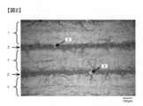
- FIG. 2 illustrates an FRP that does not fall under the present invention and is produced by a manufacturing method different from that of the FRP of FIG. 1 using the same reinforcing fiber, the same matrix resin, and the same conductive particles (same content) as the FRP of FIG. ing.
- Conductive particles 3 are also observed in the resin layer 2 of FIG. 2, but the boundary lines of the reinforcing fiber layers 1 ′ and 1 ′′ in the vicinity of the conductive particles 3 are substantially straight lines, and in the arc shape as in the region A of FIG.
- the thickness of the resin layer is 39 ⁇ m and the conductivity in the thickness direction is 16 S / m in the FRP of FIG. 1, whereas the FRP of FIG. 2 is a resin.
- the thickness of the layer was as thick as 47 ⁇ m, while the conductivity in the thickness direction was 13 S / m, which was lower than that of the FRP of FIG.
- the conductive particles "sink" into the reinforcing fiber layer to reduce the thickness of the resin layer between the reinforcing fiber layers.
- the above-mentioned "entry" of the conductive particles may occur at least in the reinforcing fiber layer on either the upper or lower side.
- the conductive particles 3 are embedded only in the lower reinforcing fiber layer 1 ′′.
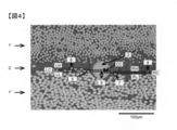
- the boundary line between the reinforcing fiber layer 1 "and the resin layer 2' is determined.
- An auxiliary line LL (indicated by a thin broken line) is drawn at the center of the reinforcing fiber (denoted as 5).
- Draw an auxiliary line LH (indicated by a fine broken line) in the center of (in FIG.
- the length is 100 ⁇ m to the left from the center of the reinforcing fiber 5), and draw an auxiliary line LC between the auxiliary line LL and the auxiliary line LH.
- FIG. 4 the reinforcing fiber 5 and the reinforcing fiber 6 are shown by being surrounded by a white oval.
- FIG. 4 the reinforcing fiber layer 1 ”is shown.
- the reinforcing fiber cross section is elliptical because the reinforcing fibers of the reinforcing fiber layer 1 "are arranged at 45 °. The same operation is performed on the right side, and auxiliary lines RL, RH, and RC are drawn.
- auxiliary line CC (indicated by a solid line) is drawn between LC and RC, and the boundary line between the reinforcing fiber layer 1 "and the resin layer 2'is at the apex of the portion where the boundary line is recessed in an arc shape from the auxiliary line CC.
- Draw a vertical line (indicated by a solid double-dashed line) toward it, and set this length as "Meripping length 9". All auxiliary lines shall be drawn so as to be parallel to the resin layer.
- the "merging length" is 21 ⁇ m. Then, the value obtained by dividing the length of the conductive particles sunk by the cross-sectional diameter of the conductive particles is defined as the amount of the sunk of the conductive particles.
- the cross-sectional diameter of the conductive particles 3 in the A region is measured, it is 53 ⁇ m, so that the amount of penetration is 40%.
- the amount of sinking three conductive particles connecting the reinforcing fiber layers are randomly selected, and the average value is taken.
- the amount of digging is preferably 10% or more. It is more preferably 15% or more, still more preferably 20% or more.
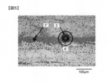
- FIG. 1 Another cross section of the FRP of the present invention is shown in FIG.
- two black circles 3', 3 "(regions considered to be traces of the conductive particles cracking and partially falling off (hereinafter, the same applies)) can be observed.
- the central part of the black circles 3', 3" appears white. From this, it is considered that these are traces of the conductive particles cracking and partially falling off during the preparation of the cross section.
- the region indicated by A'on the right side is considered to be a "sunk" portion of the conductive particles because the boundary line of the reinforcing fiber layer above the black circle 3'is recessed in an arc shape.
- the cross-sectional photograph as shown in FIG. 5 is not used for calculating the sinking amount.
- a cross-sectional photograph in which the conductive particles 3 can be clearly observed is used as shown in FIG.
- the black circle 3 "on the left side of FIG. 5 is not a" recessed "part because the boundary line between the upper and lower reinforcing fiber layers is not a clear arc shape.
- the number of conductive particles embedded in the reinforcing fiber layer is two or more per 50 mm of resin layer length.
- the number of conductive particles embedded in the reinforcing fiber layer around the resin layer length of 50 mm may be referred to as the penetration frequency.
- the immersive conductive particles are those in which the conductive particles can be clearly observed, as shown in the region A of FIG.
- the resin layer length means the length (L) of a straight line passing through the central portion of the resin layer when the FRP cross-sectional photograph is taken.
- the magnification when taking a cross-sectional photograph is 200 times.
- FIG. 3 shows a diagram illustrating the length of the resin layer in the cross section of the FRP of the present invention.
- the polymer particles flow into the periphery where the conductive particles are embedded in the reinforcing fibers. Focusing on the region B in FIG. 1, it can be seen that the boundary between the reinforcing fiber layer 1 and the resin layer 2 is recessed in an elliptical arc shape. Then, it can be seen that the polymer particles 4 are flowing into the dent. This indicates that the polymer particles 4 flow into the periphery of the conductive particles 3 sunk into the reinforcing fiber layer 1. In the FRP of FIG. 1, the polymer particles 4 are contained in the resin layer 2, but when the polymer particles 4 flow into the recesses, the abundance of the polymer particles 4 in the resin layer decreases, and as a result, the resin layer thickness.
- interleaf structure polymer particles, which are interlayer strengthening particles, act as spacers and control the interlayer thickness, and it is considered that such a situation occurs.
- conductive particles larger than the polymer particles act as spacers to determine the resin layer thickness, but as shown in FIGS. 1 and 2, the frequency of the conductive particles is orders of magnitude lower than that of the polymer particles, so this is a major measure.
- the polymer particles, which are the components dominate the thickness of the resin layer. By reducing the thickness of the resin layer, the conductivity of the FRP in the thickness direction is improved.
- the thickness of the resin layer and the linearity of the reinforcing fibers are as uniform as possible in the portion other than the "embedded" portion from the viewpoint of improving the mechanical characteristics of the FRP.
- metal particles, metal oxide particles, metal-coated inorganic particles, organic polymer particles, carbon particles and the like can be used as the conductive particles used in the present invention.
- carbon particles are preferable because they do not have a problem of corrosion even when used in an aircraft.
- ICB manufactured by Nippon Carbon Co., Ltd. has a (002) plane spacing of 3.53 angstroms, and carbon particles having a substantially spherical shape can be described as carbon, No. 168, 157-163 (1995). It is described in.
- the spherical carbon particles are very hard and are not easily deformed even if they are subjected to compression deformation, and the particle shape is restored when the compression is removed.
- FRP fluorescence-activated polymer
- the structural material is deformed as typified by the bending of the main wing during flight, but for FRP containing spherical carbon particles, the spherical carbon particles are irreversible. It is expected that stable conductivity will be exhibited because it is difficult to have a specific deformation. Further, if necessary, a conductive filler / short fiber or a conductive nanomaterial can be used in combination.
- polymer particles in the resin layer sandwiched between the plurality of reinforcing fiber layers from the viewpoint of interlayer reinforcement.
- the interlayer toughness of the FRP can be improved, and the impact resistance, which is important for aircraft applications, can be improved.
- polymer particles polyamide particles and polyimide particles can be preferably used, and polyamide particles, which can greatly improve impact resistance due to its excellent toughness, are most preferable.
- the polyamide is nylon 12, nylon 11, nylon 6, nylon 66 or nylon 6/12 copolymer, and the epoxy compound described in Example 1 of JP-A No. 01-104624, which is a semi-IPN (polymer interpenetrating network structure).
- Nylon poly-IPN nylon
- the shape of the polymer particles is spherical, particularly true spherical, because the effect of improving the impact resistance of FRP is high. More specifically, the sphericity of the polymer particles is preferably 85% or more, more preferably 90% or more.
- the sphericity is determined by randomly selecting 30 particles from the FRP cross-sectional photograph and following the following formulas from the minor axis and the major axis.
- S sphericity (%), a: major diameter, b: minor diameter, n: number of measurements 30.
- spherical polymer particles include SP-500 and SP-10 (manufactured by Toray Co., Ltd.) as polyamide-based products, and MBX series such as MBX-12 and SSX-series such as SSX-115 as polymethylmethacrylate-based products. (Sekisui Chemicals Co., Ltd.), SBX series such as SBX-12 for polystyrene (manufactured by Sekisui Chemicals Co., Ltd.), and MSX and SMX (Sekisui Chemicals Co., Ltd.) as their copolymers.
- Polyurethane type includes Dimic Beads CM series
- polystyrene acetate type includes BELLOCEA (manufactured by Daicel Co., Ltd.)
- phenol resin type includes Marilyn (manufactured by Gunei Chemical Co., Ltd.).
- examples of the true spherical particles made of polyamide and its copolymer include polyamide-based particles described in Example 1 of JP-A-1-104624 and polyamide-based particles described in WO2018 / 207728.
- the true spherical particles of the polyether sulfone system for example, those described in JP-A-2017-197665 can be exemplified.
- the polyamide-based particles described in Example 1 of JP-A-1-104624 are preferable because they are excellent in moisture resistance, chemical resistance and the like, and are also excellent in impact resistance developing effect when made into FRP.
- the particle size of the polymer particles added at the time of producing the intermediate base material is preferably 5 ⁇ m or more and 45 ⁇ m or less in the mode diameter determined by the light scattering method. By setting the mode diameter of the polymer particles to this range, stable impact resistance can be imparted when FRP is used. It is more preferable that the mode diameter of the polymer particles is 10 to 20 ⁇ m.
- the particle size can be measured by applying a light scattering method, for example, using a Partica LA-950V2 manufactured by Horiba, MT3300II manufactured by Microtrac, or a SALD series manufactured by Shimadzu.
- the matrix resin used for the FRP of the present invention preferably contains a thermosetting resin, a thermoplastic resin and a curing agent, but may be only a thermosetting resin and a curing agent or a thermoplastic resin.
- a thermosetting resin an epoxy resin is generally used.
- an epoxy resin having amines, phenols, or a compound having a carbon / carbon double bond as a precursor is preferable.
- epoxy resins using amines as precursors various isomers of tetraglycidyldiaminodiphenylmethane, triglycidyl-p-aminophenol, triglycidyl-m-aminophenol, and triglycidylaminocresol; phenols are precursors.
- body epoxy resin bisphenol A type epoxy resin, bisphenol F type epoxy resin, bisphenol S type epoxy resin, phenol novolac type epoxy resin, cresol novolac type epoxy resin; a compound having a carbon-carbon double bond as a precursor.
- the epoxy resin to be used include, but are not limited to, an alicyclic epoxy resin.
- the epoxy resin contained in the matrix resin it is also preferable to use at least one resin selected from a dicyclopentadiene type epoxy resin having a rigid skeleton and a glycidylaniline type epoxy resin which is a pendant type epoxy resin.
- a dicyclopentadiene type epoxy resin is used, the epoxy equivalent is set to 200 g / eq or more and 265 g / eq or less to improve the compatibility with the thermoplastic resin (particularly the polyether sulfone) used in combination. ,preferable.
- the glycidyl aniline type epoxy resin or the dicyclopentadiene type epoxy resin can be applied to both the primary resin composition and the secondary resin composition, but when used in at least the secondary resin composition, the tensile strength of the FRP is improved. It is preferable because the effect can be seen.
- a bromoized epoxy resin obtained by bromoizing these epoxy resins is also used.
- Epoxy resins using aromatic amines as precursors, such as tetraglycidyldiaminodiphenylmethane, are most suitable for the present invention because they have good heat resistance and good adhesion to reinforcing fibers.
- thermosetting resin is preferably used in combination with a curing agent.
- the curing agent may be a compound having an active group capable of reacting with the epoxy group.
- a compound having an amino group, an acid anhydride group or an azide group is preferably suitable.
- dicyandiamide, various isomers of diaminodiphenyl sulfone, aminobenzoic acid esters and the like are suitable.
- Dicyandiamide is preferred because it has excellent prepreg storage stability.
- various isomers of diaminodiphenyl sulfone are most suitable for the present invention because they give a cured product having good heat resistance.
- trimethylene glycol di-p-aminobenzoate and neopentyl glycol di-p-aminobenzoate are preferably used, and although they are inferior in heat resistance to diaminodiphenyl sulfone, they have higher tensile strength. Because it is excellent, it is selected and used according to the application. It is also possible to use a curing catalyst if necessary. Further, in order to improve the pot life of the coating liquid, it is also possible to use a curing agent or a curing catalyst and a complexing agent capable of forming a complex in combination.
- thermosetting resin mixed with a thermoplastic resin gives better results than when the thermosetting resin is used alone. This is because thermosetting resins can be low-pressure molded by autoclave while having the drawback of being generally brittle, whereas low-pressure molding by autoclave is difficult while thermoplastic resins have the advantage of being generally tough. This is because it is possible to balance the physical properties and the moldability by using a mixture of these to show the contradictory characteristics.
- the thermosetting resin and the thermoplastic resin it is preferable to contain more than 50% by mass of the thermosetting resin from the viewpoint of the mechanical properties of the FRP obtained by curing the prepreg.
- the thermoplastic resin is selected from carbon-carbon bonds, amide bonds, imide bonds, ester bonds, ether bonds, carbonate bonds, urethane bonds, urea bonds, thioether bonds, sulfone bonds, imidazole bonds and carbonyl bonds in the main chain.
- Polymers with bonds can be used. Specifically, polyacrylate, polyolefin, polyamide (PA), aramid, polyester, polycarbonate (PC), polyphenylene sulfide (PPS), polybenzoimidazole (PBI), polyimide (PI), polyetherimide (PEI), polysulfone.
- PSU polyethersulfone
- PES polyetherketone
- PEK polyetheretherketone
- PEEK polyetherketoneketone
- PAEK polyaryletherketone
- PAI polyamideimide
- the FRP of the present invention has a conductivity of 1 S / m or more in the thickness direction as long as it is 1 S / m or more. It may be possible to simplify the lightning protection system in the aircraft, which is preferable.
- the conductivity is more preferably 5 S / m or more, still more preferably 15 S / m or more.
- the post-impact compressive strength CAI (Compression Strength After Impact) of FRP which is an important index of impact resistance in aircraft applications, is preferably 250 MPa or more, more preferably 280 MPa or more.
- the FRP of the present invention is used as a structural material for an aircraft, it is preferable to use a prepreg using a UD material as a reinforcing fiber layer as an intermediate base material. Further, from this meaning, it is preferable to use carbon fiber as the reinforcing fiber.
- a reinforcing fiber fabric or glass fiber can also be used as the reinforcing fiber layer.
- the prepreg used in the present invention is a reinforcing fiber layer impregnated with a resin composition.
- a method for producing a prepreg a step of impregnating a reinforcing fiber layer with a primary resin composition using a primary resin composition film to obtain a primary prepreg, and a step of using a secondary resin composition film for the primary prepreg are used. It is preferable to use a two-stage impregnation method including a step of applying a secondary resin composition to obtain a prepreg.
- thermosetting resin as the matrix resin
- carbon fiber UD material as the reinforcing fiber layer
- a primary resin composition containing an epoxy resin, an aromatic amine-type curing agent and a thermoplastic resin is prepared for the primary prepreg by kneading.
- a primary resin composition film is produced by applying the primary resin composition onto a base material (paper pattern) using a roll coater. After that, the carbon fiber bundles are aligned to form a UD sheet, the primary resin composition film is applied from above and below the carbon fiber bundle, and after preheating, the pressure is applied with a nip roll to impregnate the UD sheet with the primary resin composition. Thereby, a primary prepreg is obtained. At this time, it is preferable to increase the degree of impregnation of the primary prepreg.
- a secondary resin composition containing an epoxy resin, an aromatic amine type curing agent, a thermoplastic resin, polymer particles and conductive particles was prepared, and also applied on a substrate (release paper) using a roll coater.
- a secondary resin composition film is prepared.
- a blade coater such as a knife coater is generally used as a coater.
- a knife coater is used in each of the examples of Patent Documents 1 and 2 mentioned in the background art.
- the blade coater determines the amount of resin coating by the clearance between the blade and the base material, it is difficult for conductive particles having a large particle size to pass through the coater.
- the conductive particles having a large particle size dig into the reinforcing fiber layer and thereby reduce the thickness of the resin layer, the conductive particles having a large particle size are contained in the secondary resin composition film. It is one of the points of prepreg production.
- a roll coater is preferably used when producing a secondary resin composition film. Since the roll coater transfers the feed resin to the roll and further transfers it to a base material (such as a paper pattern), even conductive particles having an essentially large particle size have good coater passability. Since it is important for the roll coater to uniformly transfer the resin onto the transfer roll and to make the film thickness uniform, it is often the case that an opposed roll facing the transfer roll is arranged. Even at this time, if the amount of resin supplied per unit time increases, the resin pressure at the clearance between the transfer roll and the opposing roll increases, but since the roll itself is thick, it is difficult to bend even when the resin pressure becomes high, and the upper limit of the amount of resin supplied.
- the clearance can be increased according to the resin pressure, and from this viewpoint as well, it is easy for conductive particles having a large particle size to pass through.
- the resin to be coated can be stretched between the transfer roll and the traveling base material, and the amount of the supplied resin can be further increased. From these, it is preferable to prepare the secondary resin composition film with a roll coater because it is easy for conductive particles having a large particle size to pass through.
- the secondary resin composition film is applied from both the upper and lower sides of the primary prepreg, and after preheating, the film is pressed with a nip roll to obtain the prepreg on which the secondary resin composition is applied. At this time, it is desirable to sufficiently preheat the secondary resin composition to ensure sufficient fluidity.
- the prepreg by the two-stage impregnation method as described above it is easy to form a structure in which the conductive particles having a large particle size are embedded in the reinforcing fiber layer, and the parts other than the "embedded" portion are compared. Since the resin layer thickness can be made uniform, the obtained FRP is not only highly conductive in the thickness direction, but also advantageous from the viewpoint of mechanical properties.
- the prepreg tape can be obtained by slitting the prepreg into a narrow width.
- a method such as share cut, score cut, leather cut, heat cut, water jet cut, ultrasonic cut and the like can be used.
- FRP can be produced by pressurizing and heating as necessary to shape and cure the resin.
- a heat-pressing molding method or the like can be used. More specifically, a press molding method, an autoclave molding method, a bagging molding method, a wrapping tape method, an internal pressure molding method and the like can be used.
- the molding is preferably performed at a temperature in the range of 150 ° C to 220 ° C.
- the pressure for molding FRP by the autoclave molding method varies depending on the thickness of the prepreg and the volume content of the reinforcing fibers, but is usually in the range of 0.1 to 1 MPa. As a result, it is possible to obtain an FRP that does not have defects such as voids in the obtained FRP and has little dimensional fluctuation such as warpage.
- the FRP of the present invention can be suitably used for aircraft structures.
- aircraft structures flat plate structures, cylindrical structures, box-shaped structures, C-shaped structures, H-shaped structures, L-shaped structures, T-shaped structures, I-shaped structures, Z-shaped structures, It is selected from hat-shaped structures and the like.
- aircraft parts are constructed. Details are described in, for example, "Structural Design of Airplanes", 5th edition, Torikai / Kuze, Japan Aviation Technology Association (2003).
- Such a structure can be obtained by shaping a prepreg as described in, for example, International Publication WO2017 / 110991 [0084], International Publication WO2016 / 043156 [0073], and International Publication WO2019 / 0314078 [0088]. Can be done. Further, a structure having a desired shape can also be obtained by automatically laminating the prepreg tape on the mold having the desired shape and then curing the prepreg tape.
- the fuselage, main wing, central wing, tail wing, etc. are formed by the joined structure in which the above structures are joined together.
- a so-called fastener such as a bolt or a rivet may be used, or an adhesive film or the like may be used.
- a cocure method in which an uncured prepreg laminate or a semi-cured prepreg laminate is bonded and then cured.
- the unit "part" of the composition ratio means a mass part unless otherwise specified.
- the various characteristics (physical properties) were measured in an environment with a temperature of 23 ° C. and a relative humidity of 50% unless otherwise specified.
- Epoxy resin ⁇ "EPICLON” HP-7200L (dicyclopentadiene type epoxy resin, epoxy equivalent 246 g / eq, manufactured by DIC Corporation) "Sumiepoxy” ELM434 (Tetraglycidiaminodiphenylmethane, manufactured by Sumitomo Chemical Co., Ltd., epoxy equivalent 120 g / eq).
- EPICLON 830 bisphenol F type epoxy resin, manufactured by DIC Corporation, epoxy equivalent 171 g / eq) -JER825 (bisphenol A type epoxy resin, manufactured by Mitsubishi Chemical Corporation, epoxy equivalent 170-180 g / eq) -GOT (glycidyl aniline type epoxy resin (N, N-diglycidyl-o-toluidine), manufactured by Nippon Kayaku Co., Ltd.).
- Polymer particles 6 spherical polyamide particles obtained by the following production method (mode diameter 15 ⁇ m, sphericity 96%).
- the particle size was measured using MT3300II (light source 780 nm-3 mW, wet cell (medium: water)) manufactured by Microtrac.
- an autoclave with a 3 L helical ribbon type stirring blade 200 g of ⁇ -caprolactam (manufactured by Toray Industries, Inc.), polyethylene glycol (Wako Pure Chemical Industries, Ltd.) as the second component polymer.
- Primary polyethylene glycol manufactured by Kogyo Co., Ltd., 20,000, weight average molecular weight 18,600), 800 g, and 1,000 g of water were added to form a uniform solution, which was then sealed and replaced with nitrogen. Then, the stirring speed was set to 100 rpm and the temperature was raised to 240 ° C.
- the pressure of the system reached 10 kg / cm 2
- the pressure was controlled while slightly releasing the water vapor so as to maintain the pressure at 10 kg / cm 2.
- the pressure was released at a rate of 0.2 kg / cm 2 ⁇ min.
- the temperature was maintained for 1 hour while flowing nitrogen to complete the polymerization, and the slurry was discharged into a 2,000 g water bath to obtain a slurry.
- filtration was performed, 2,000 g of water was added to the filter medium, and the mixture was washed at 80 ° C.
- the slurry liquid from which the agglomerates had been passed through a 200 ⁇ m sieve was filtered again, and the isolated filter medium was dried at 80 ° C. for 12 hours to obtain 140 g of polyamide 6 powder.
- the melting point of the obtained powder was 218 ° C., which was the same as that of polyamide 6, and the crystallization temperature was 170 ° C.
- Conductive particles (carbon particles) "Nika beads” ICB average particle size (number basis): 27 ⁇ m, manufactured by Nippon Carbon Co., Ltd.).
- Conductive aid carbon black
- Mitsubishi “Carbon Black”# 3230B particle diameter of primary particles 23 nm (arithmetic average diameter obtained by observing carbon black particles with an electron microscope), manufactured by Mitsubishi Chemical Corporation.
- the epoxy resin and the thermoplastic resin were kneaded, the temperature was raised to 150 ° C. or higher, and the mixture was stirred as it was for 1 hour to dissolve the thermoplastic resin and obtain a transparent viscous liquid. After lowering the temperature while kneading this liquid, a curing agent, polymer particles, and conductive particles were added and kneaded to obtain a secondary resin composition.
- Table 1 shows the composition ratios of the resin compositions of each Example and Comparative Example.
- the prepreg of the example was prepared by using the two-stage impregnation method as follows.
- the primary resin composition or the secondary resin composition prepared in (1) above was uniformly applied onto the silicone-coated release paper using a roll coater equipped with an opposed roll, and each of them was a primary resin composition.
- a film and a secondary resin composition film were obtained.
- the winding speed of the resin film is set to 15 m / min, and the resin is stretched between the transfer roll and the traveling paper pattern, so that the resin is supplied per unit time. The amount of resin was increased and the clearance at the roll coater was sufficiently large.
- the carbon fibers uniformly aligned in one direction were sandwiched between the two primary resin composition films, heated and pressed using a press roll, and the carbon fibers were sufficiently impregnated with the primary resin composition.
- a primary prepreg was obtained (carbon fiber texture was 268 g / cm 2 , resin content was 20% by mass).
- the paper pattern was peeled off from the obtained primary prepreg.
- the primary prepreg was sandwiched between two secondary resin composition films, heated and pressurized using a press roll to obtain a prepreg in which the primary prepreg was impregnated with the secondary resin composition (1).
- Carbon fiber grain 268 g / cm 2 resin content 34% by mass).
- the resin film was prepared using a general knife coater.
- the winding speed of the resin film at the time of producing the secondary resin composition film was 2 m / min.
- the primary prepreg and the prepreg were prepared in the same manner as in Examples.
- a cut sample of about 20 mm ⁇ 20 mm was obtained from the obtained CFRP, embedded and cured with epoxy resin, and then the edge portion was polished. This polished surface was observed using a digital microscope VHX-5000 manufactured by KEYENCE CORPORATION.
- the magnification was basically set to 200 times, but there were cases where the magnification was adjusted as necessary to improve the resolution and grasp the overall image.
- the penetration frequency is the number of carbon particles embedded in the CF layer around the resin layer length of 50 mm.
- the resin layer length means the length (L) of a straight line passing through the central portion of the resin layer when a CFRP cross-sectional photograph is taken.
- the magnification when taking a cross-sectional photograph is 200 times.
- CFRP cross-sectional photographs are taken by randomly selecting a number of sheets that can obtain a sufficient length of the resin layer (total length of 50 mm or more).
- auxiliary line LL is drawn at the center of the reinforcing fiber 5 closest to the conductive particles on the left side of the conductive particles 3, and 100 ⁇ m to the left from the reinforcing fibers.
- auxiliary line RC right side auxiliary
- the line is omitted).
- an auxiliary line CC is drawn between LC and RC.
- the boundary line between the reinforcing fiber layer 1 "and the resin layer 2' is recessed in an arc shape from the auxiliary line CC.
- a vertical line is drawn toward the apex of the portion, and this length is defined as the sunk length 9 of the conductive particles.
- the sunk amount is a value obtained by dividing the sunk length of the carbon particles of interest by the cross-sectional diameter of the conductive particles. Three conductive particles connecting the reinforcing fiber layers were randomly selected, the amount of penetration was measured, and the average value was calculated.
- S sphericity (%), a: major diameter, b: minor diameter, n: number of measurements 30.
- Resin layer thickness In the CFRP cross-sectional photograph obtained in (3), the area of the resin layer is obtained using the image analysis software Winroof, and the area is divided by the length of the target resin layer to obtain the resin layer 1 in the cross-sectional photograph. The layer thickness was calculated. This was done with 8 randomly selected layers, and the average value of the resin layer thickness was calculated.
- CFRP Conductivity in the thickness direction of CFRP
- the prepregs obtained as described above are laminated in a pseudo-isotropic manner with 16 plies in a [+ 45 ° / 0 ° / ⁇ 45 ° / 90 °] 2s configuration, and then autoclaved.
- CFRP was prepared by curing the resin at a temperature of 180 ° C. for 2 hours at a pressure of 6 kg / cm 2 and a heating rate of 1.5 ° C./min.
- the prepreg obtained as described above is cut to a predetermined size, four sheets are laminated in one direction, a vacuum bag is performed, and the temperature is 180 ° C. using an autoclave. cured at a pressure 6 kg / cm 2, 2 hours to obtain a unidirectional reinforcement.
- the obtained unidirectional reinforcing material was cut to a width of 12.7 mm and a length of 230 mm, and tabs made of glass fiber reinforced plastic having a width of 1.2 mm and a length of 50 mm were adhered to both ends to obtain a test piece.
- This test piece was subjected to a 0 ° tensile test using an Instron universal tester according to the JIS K7073 (1988) standard. The measurement temperature was room temperature (23 ° C.).
- CFRP post-impact compressive strength (CAI)
- the prepregs obtained as described above were laminated in a pseudo-isotropically 16-ply configuration with a [+ 45 ° / 0 ° / ⁇ 45 ° / 90 °] 2s configuration, and then autoclaved at a temperature of 180 ° C. for 2 hours.
- CFRP was prepared by curing the resin at a pressure of 6 kg / cm 2 and a heating rate of 1.5 ° C./min.
- a sample of 150 mm in length ⁇ 100 mm in width was cut out from the obtained CFRP, and a compressive fracture test was performed after applying a drop impact of 6.7 J / mm to the center of the sample according to SACMA SRM 2R-94.
- the compressive strength (CAI) was determined.
- Example 1 A prepreg was prepared according to the method (2) above with the composition shown in Table 1, and CFRP (flat plate structure) was evaluated as described above. At this time, the content of the carbon particles is 1.0% by mass with respect to the total mass of the epoxy resin, the curing agent, the thermoplastic resin, the carbon particles and the carbon black, and the content of the carbon black is the epoxy resin, the curing agent. It was 1.5% by mass with respect to the total mass of the thermoplastic resin, carbon particles and carbon black.
- this CFRP was observed, as shown in FIG. 1, there was a portion where the upper and lower carbon fiber layers were connected by one carbon particle, and further, it was confirmed that the carbon particles were "sunk".
- the average thickness of the resin layer was thin and the conductivity in the thickness direction was high. From this, it was considered possible to reduce the amount of carbon particles added as compared with Comparative Example 1 when the conductivity was the same.
- Example 1 A prepreg was prepared from the same carbon fiber and resin composition (including polymer particles, carbon particles, and carbon black) as in Example 1, and CFRP (flat plate structure) was prepared in the same manner as in Example 1. A typical example of this cross-sectional observation photograph is shown in FIG. 2, but no "sinking" of carbon particles was observed.
- Example 2 CFRP (plate structure) was prepared in the same manner as in Example 1 with the composition shown in Table 1. At this time, the content of the carbon particles was 1.0% by mass with respect to the total mass of the epoxy resin, the curing agent, the thermoplastic resin and the carbon particles. When the cross section of this was observed, there was a part where the upper and lower carbon fiber layers were connected by one carbon particle, and it was confirmed that the carbon particles were "sunk". The conductivity in the thickness direction was also sufficiently high at 12 S / m.
- Example 3 CFRP (plate structure) was prepared in the same manner as in Example 1 with the composition shown in Table 1. At this time, the content of the carbon particles was 1.0% by mass with respect to the total mass of the epoxy resin, the curing agent, the thermoplastic resin and the carbon particles. When the cross section of this was observed, there was a part where the upper and lower carbon fiber layers were connected by one carbon particle, and it was confirmed that the carbon particles were "sunk”. The conductivity in the thickness direction was also sufficiently high at 13 S / m.
- Example 4 CFRP (plate structure) was prepared in the same manner as in Example 1 with the composition shown in Table 1. At this time, the content of the carbon particles was 1.0% by mass with respect to the total mass of the epoxy resin, the curing agent, the thermoplastic resin, the carbon particles and the carbon black. When the cross section of this was observed, there was a part where the upper and lower carbon fiber layers were connected by one carbon particle, and it was confirmed that the carbon particles were "sunk”. Since carbon black, which is a conductive auxiliary agent, was also used, the conductivity in the thickness direction was 18 S / m, which was higher than that of Example 3.
- Example 5 CFRP (plate structure) was prepared in the same manner as in Example 1 with the composition shown in Table 1. When the cross section of this was observed, there was a part where the upper and lower carbon fiber layers were connected by one carbon particle, and it was confirmed that the carbon particles were "sunk”. The thickness direction conductivity was 8 S / m.
- the FRP of the present invention can be widely applied to industrial fields where conductivity is required for materials.
- it when it is used as a structural member of an aircraft, it can be suitably used in the field because it can reduce conventional lightning protection systems such as metal foils and metal meshes, static elimination systems, electromagnetic wave shielding systems and the like.
Landscapes
- Engineering & Computer Science (AREA)
- Mechanical Engineering (AREA)
- Chemical & Material Sciences (AREA)
- Composite Materials (AREA)
- Physics & Mathematics (AREA)
- Mathematical Physics (AREA)
- Reinforced Plastic Materials (AREA)
Abstract
L'invention concerne un matériau composite renforcé par des fibres qui : comprend une couche de résine prise en sandwich par des couches de fibres de renforcement ; présente une partie dans laquelle des particules électroconductrices présentant une sphéricité supérieure ou égale à 85 % sont disposées dans la couche de résine et dans laquelle les couches de renforcement dans le haut et dans le bas sont reliées par l'intermédiaire de l'une des particules électroconductrices ; et présente une partie dans laquelle les particules électroconductrices s'enfoncent dans les couches de fibres de renforcement. L'invention concerne le matériau composite renforcé par des fibres présentant une électroconductivité suffisante dans la direction d'épaisseur correspondante, à l'aide de seulement une petite quantité de particules électroconductrices ajoutées en son sein.
Priority Applications (3)
| Application Number | Priority Date | Filing Date | Title |
|---|---|---|---|
| EP21833608.9A EP4140676A4 (fr) | 2020-06-30 | 2021-06-25 | Matériau composite renforcé par des fibres et procédé de production de préimprégné |
| US18/010,644 US20230339222A1 (en) | 2020-06-30 | 2021-06-25 | Fiber-reinforced composite material and method for producing prepreg |
| JP2021538973A JPWO2022004586A1 (fr) | 2020-06-30 | 2021-06-25 |
Applications Claiming Priority (2)
| Application Number | Priority Date | Filing Date | Title |
|---|---|---|---|
| JP2020112487 | 2020-06-30 | ||
| JP2020-112487 | 2020-06-30 |
Publications (1)
| Publication Number | Publication Date |
|---|---|
| WO2022004586A1 true WO2022004586A1 (fr) | 2022-01-06 |
Family
ID=79316080
Family Applications (1)
| Application Number | Title | Priority Date | Filing Date |
|---|---|---|---|
| PCT/JP2021/024107 WO2022004586A1 (fr) | 2020-06-30 | 2021-06-25 | Matériau composite renforcé par des fibres et procédé de production de préimprégné |
Country Status (4)
| Country | Link |
|---|---|
| US (1) | US20230339222A1 (fr) |
| EP (1) | EP4140676A4 (fr) |
| JP (1) | JPWO2022004586A1 (fr) |
| WO (1) | WO2022004586A1 (fr) |
Cited By (1)
| Publication number | Priority date | Publication date | Assignee | Title |
|---|---|---|---|---|
| WO2023074733A1 (fr) * | 2021-10-27 | 2023-05-04 | 東レ株式会社 | Matériau composite renforcé par des fibres de carbone |
Citations (12)
| Publication number | Priority date | Publication date | Assignee | Title |
|---|---|---|---|---|
| JPH01104624A (ja) | 1987-10-16 | 1989-04-21 | Toray Ind Inc | 樹脂微粒子を用いたプリプレグ |
| WO2008018421A1 (fr) | 2006-08-07 | 2008-02-14 | Toray Industries, Inc. | Préimprégné et matériau composite renforcé avec des fibres de carbone |
| WO2008056123A1 (fr) | 2006-11-06 | 2008-05-15 | Hexcel Composites Limited | Matières composites améliorées |
| WO2012084197A1 (fr) | 2010-12-21 | 2012-06-28 | Hexcel Composites Limited | Améliorations dans des matériaux composites |
| WO2012124450A1 (fr) | 2011-03-17 | 2012-09-20 | 東レ株式会社 | Pré-imprégné, procédé de fabrication du pré-imprégné et matière composite renforcée par des fibres de carbone |
| JP2013067750A (ja) | 2011-09-26 | 2013-04-18 | Toray Ind Inc | プリプレグおよび炭素繊維強化複合材料 |
| WO2014050896A1 (fr) * | 2012-09-26 | 2014-04-03 | 東邦テナックス株式会社 | Préimprégné et son procédé de fabrication |
| WO2016043156A1 (fr) | 2014-09-19 | 2016-03-24 | 東レ株式会社 | Pré-imprégné encoché et feuille de pré-imprégné encoché |
| WO2017110991A1 (fr) | 2015-12-25 | 2017-06-29 | 東レ株式会社 | Préimprégné et son procédé de fabrication |
| JP2017197665A (ja) | 2016-04-28 | 2017-11-02 | 東レ株式会社 | ポリエーテルスルホン樹脂粒子の製造方法およびポリエーテルスルホン樹脂粒子 |
| WO2018207728A1 (fr) | 2017-05-12 | 2018-11-15 | 東レ株式会社 | Procédé de production de particules fines de polyamide, et particules fines de polyamide |
| WO2019031407A1 (fr) | 2017-08-08 | 2019-02-14 | パイオニア株式会社 | Dispositif et procédé de détermination ainsi que programme |
Family Cites Families (1)
| Publication number | Priority date | Publication date | Assignee | Title |
|---|---|---|---|---|
| GB201206885D0 (en) * | 2012-04-19 | 2012-06-06 | Cytec Tech Corp | Composite materials |
-
2021
- 2021-06-25 JP JP2021538973A patent/JPWO2022004586A1/ja active Pending
- 2021-06-25 EP EP21833608.9A patent/EP4140676A4/fr active Pending
- 2021-06-25 WO PCT/JP2021/024107 patent/WO2022004586A1/fr unknown
- 2021-06-25 US US18/010,644 patent/US20230339222A1/en active Pending
Patent Citations (12)
| Publication number | Priority date | Publication date | Assignee | Title |
|---|---|---|---|---|
| JPH01104624A (ja) | 1987-10-16 | 1989-04-21 | Toray Ind Inc | 樹脂微粒子を用いたプリプレグ |
| WO2008018421A1 (fr) | 2006-08-07 | 2008-02-14 | Toray Industries, Inc. | Préimprégné et matériau composite renforcé avec des fibres de carbone |
| WO2008056123A1 (fr) | 2006-11-06 | 2008-05-15 | Hexcel Composites Limited | Matières composites améliorées |
| WO2012084197A1 (fr) | 2010-12-21 | 2012-06-28 | Hexcel Composites Limited | Améliorations dans des matériaux composites |
| WO2012124450A1 (fr) | 2011-03-17 | 2012-09-20 | 東レ株式会社 | Pré-imprégné, procédé de fabrication du pré-imprégné et matière composite renforcée par des fibres de carbone |
| JP2013067750A (ja) | 2011-09-26 | 2013-04-18 | Toray Ind Inc | プリプレグおよび炭素繊維強化複合材料 |
| WO2014050896A1 (fr) * | 2012-09-26 | 2014-04-03 | 東邦テナックス株式会社 | Préimprégné et son procédé de fabrication |
| WO2016043156A1 (fr) | 2014-09-19 | 2016-03-24 | 東レ株式会社 | Pré-imprégné encoché et feuille de pré-imprégné encoché |
| WO2017110991A1 (fr) | 2015-12-25 | 2017-06-29 | 東レ株式会社 | Préimprégné et son procédé de fabrication |
| JP2017197665A (ja) | 2016-04-28 | 2017-11-02 | 東レ株式会社 | ポリエーテルスルホン樹脂粒子の製造方法およびポリエーテルスルホン樹脂粒子 |
| WO2018207728A1 (fr) | 2017-05-12 | 2018-11-15 | 東レ株式会社 | Procédé de production de particules fines de polyamide, et particules fines de polyamide |
| WO2019031407A1 (fr) | 2017-08-08 | 2019-02-14 | パイオニア株式会社 | Dispositif et procédé de détermination ainsi que programme |
Non-Patent Citations (3)
| Title |
|---|
| "Carbon", 1995, ICB MANUFACTURED BY NIPPON CARBON CO., pages: 157 - 163 |
| See also references of EP4140676A4 |
| TORIKAIKUZE: "Structural Design of Aircrafts", 2003, JAPAN AERONAUTICAL ENGINEERS' ASSOCIATION |
Cited By (1)
| Publication number | Priority date | Publication date | Assignee | Title |
|---|---|---|---|---|
| WO2023074733A1 (fr) * | 2021-10-27 | 2023-05-04 | 東レ株式会社 | Matériau composite renforcé par des fibres de carbone |
Also Published As
| Publication number | Publication date |
|---|---|
| EP4140676A4 (fr) | 2024-02-28 |
| EP4140676A1 (fr) | 2023-03-01 |
| US20230339222A1 (en) | 2023-10-26 |
| JPWO2022004586A1 (fr) | 2022-01-06 |
Similar Documents
| Publication | Publication Date | Title |
|---|---|---|
| US10549499B2 (en) | Composite materials with high Z-direction electrical conductivity | |
| JP5900327B2 (ja) | プリプレグ、プリプレグの製造方法および炭素繊維強化複合材料の製造方法 | |
| EP2902435B1 (fr) | Préimprégné et son procédé de fabrication | |
| JP5522199B2 (ja) | 炭素繊維強化複合材料用エポキシ樹脂組成物、プリプレグおよび炭素繊維強化複合材料 | |
| CN108472879B (zh) | 作为复合材料中的夹层的混合面纱 | |
| JP2011231331A5 (fr) | ||
| JP2011213991A (ja) | 炭素繊維強化複合材料 | |
| WO2022004586A1 (fr) | Matériau composite renforcé par des fibres et procédé de production de préimprégné | |
| JP6213225B2 (ja) | プリプレグおよび繊維強化複合材料 | |
| WO2023008357A1 (fr) | Matériau composite renforcé par des fibres de carbone | |
| WO2023074733A1 (fr) | Matériau composite renforcé par des fibres de carbone | |
| WO2023140271A1 (fr) | Procédé de production d'un préimprégné, procédé de production d'un ruban préimprégné, procédé de production d'un stratifié préimprégné et procédé de production d'un matériau composite renforcé par des fibres de carbone | |
| WO2023190319A1 (fr) | Matériau composite renforcé par des fibres de carbone et préimprégné | |
| JP2013067750A (ja) | プリプレグおよび炭素繊維強化複合材料 | |
| JP2023106337A (ja) | プリプレグ、プリプレグロール、プリプレグテープ、プリプレグ積層体、炭素繊維強化複合材料および構造体 |
Legal Events
| Date | Code | Title | Description |
|---|---|---|---|
| ENP | Entry into the national phase |
Ref document number: 2021538973 Country of ref document: JP Kind code of ref document: A |
|
| 121 | Ep: the epo has been informed by wipo that ep was designated in this application |
Ref document number: 21833608 Country of ref document: EP Kind code of ref document: A1 |
|
| ENP | Entry into the national phase |
Ref document number: 2021833608 Country of ref document: EP Effective date: 20221122 |
|
| NENP | Non-entry into the national phase |
Ref country code: DE |