WO2022004514A1 - 試料ホルダー - Google Patents
試料ホルダー Download PDFInfo
- Publication number
- WO2022004514A1 WO2022004514A1 PCT/JP2021/023735 JP2021023735W WO2022004514A1 WO 2022004514 A1 WO2022004514 A1 WO 2022004514A1 JP 2021023735 W JP2021023735 W JP 2021023735W WO 2022004514 A1 WO2022004514 A1 WO 2022004514A1
- Authority
- WO
- WIPO (PCT)
- Prior art keywords
- sample holder
- heat
- refrigerant
- cooling
- sample
- Prior art date
- Legal status (The legal status is an assumption and is not a legal conclusion. Google has not performed a legal analysis and makes no representation as to the accuracy of the status listed.)
- Ceased
Links
Images


Classifications
-
- H—ELECTRICITY
- H01—ELECTRIC ELEMENTS
- H01J—ELECTRIC DISCHARGE TUBES OR DISCHARGE LAMPS
- H01J37/00—Discharge tubes with provision for introducing objects or material to be exposed to the discharge, e.g. for the purpose of examination or processing thereof
- H01J37/02—Details
- H01J37/20—Means for supporting or positioning the object or the material; Means for adjusting diaphragms or lenses associated with the support
-
- H—ELECTRICITY
- H01—ELECTRIC ELEMENTS
- H01J—ELECTRIC DISCHARGE TUBES OR DISCHARGE LAMPS
- H01J2237/00—Discharge tubes exposing object to beam, e.g. for analysis treatment, etching, imaging
- H01J2237/002—Cooling arrangements
-
- H—ELECTRICITY
- H01—ELECTRIC ELEMENTS
- H01J—ELECTRIC DISCHARGE TUBES OR DISCHARGE LAMPS
- H01J2237/00—Discharge tubes exposing object to beam, e.g. for analysis treatment, etching, imaging
- H01J2237/20—Positioning, supporting, modifying or maintaining the physical state of objects being observed or treated
- H01J2237/2001—Maintaining constant desired temperature
-
- H—ELECTRICITY
- H01—ELECTRIC ELEMENTS
- H01J—ELECTRIC DISCHARGE TUBES OR DISCHARGE LAMPS
- H01J2237/00—Discharge tubes exposing object to beam, e.g. for analysis treatment, etching, imaging
- H01J2237/20—Positioning, supporting, modifying or maintaining the physical state of objects being observed or treated
- H01J2237/2007—Holding mechanisms
-
- H—ELECTRICITY
- H01—ELECTRIC ELEMENTS
- H01J—ELECTRIC DISCHARGE TUBES OR DISCHARGE LAMPS
- H01J2237/00—Discharge tubes exposing object to beam, e.g. for analysis treatment, etching, imaging
- H01J2237/20—Positioning, supporting, modifying or maintaining the physical state of objects being observed or treated
- H01J2237/2008—Positioning, supporting, modifying or maintaining the physical state of objects being observed or treated specially adapted for studying electrical or magnetical properties of objects
-
- H—ELECTRICITY
- H01—ELECTRIC ELEMENTS
- H01J—ELECTRIC DISCHARGE TUBES OR DISCHARGE LAMPS
- H01J2237/00—Discharge tubes exposing object to beam, e.g. for analysis treatment, etching, imaging
- H01J2237/20—Positioning, supporting, modifying or maintaining the physical state of objects being observed or treated
- H01J2237/202—Movement
- H01J2237/20207—Tilt
-
- H—ELECTRICITY
- H01—ELECTRIC ELEMENTS
- H01J—ELECTRIC DISCHARGE TUBES OR DISCHARGE LAMPS
- H01J2237/00—Discharge tubes exposing object to beam, e.g. for analysis treatment, etching, imaging
- H01J2237/20—Positioning, supporting, modifying or maintaining the physical state of objects being observed or treated
- H01J2237/202—Movement
- H01J2237/20214—Rotation
-
- H—ELECTRICITY
- H01—ELECTRIC ELEMENTS
- H01J—ELECTRIC DISCHARGE TUBES OR DISCHARGE LAMPS
- H01J2237/00—Discharge tubes exposing object to beam, e.g. for analysis treatment, etching, imaging
- H01J2237/20—Positioning, supporting, modifying or maintaining the physical state of objects being observed or treated
- H01J2237/202—Movement
- H01J2237/20278—Motorised movement
Definitions
- the present invention relates to a sample holder and an electron microscope having the sample holder, and more particularly to a sample holder capable of cooling a sample and an electron microscope having the sample holder.
- the temperature control range that can be stably operated and observed with a commercially available cooling holder is generally about -269 to -100 degrees. From this point of view, there is known a sample cooling device for an electron microscope that efficiently dissipates the heat generated on the high temperature side of the Pelche element into the atmosphere and improves the cooling efficiency (Patent Document 1).
- forced convection by running water or the like is desirable in order to obtain sufficient endothermic, but in the case of forced convection, depending on the device, the microscope image may be shaken by convection or pulsating current, which may significantly reduce the resolution.
- the present invention is to provide a sample holder that can be rotated while cooling the sample.
- the present inventor has found the present invention as a result of diligent studies on the cooling mechanism of the sample holder.
- the sample holder of the present invention is close to the sample holder shaft portion having the sample and / or the sample mesh mounting portion, the outer cylinder portion capable of storing the sample holder shaft portion, the cooling portion, and the cooling portion. It is characterized by having an installed thermoelectric element.
- thermoelectric element is characterized by being a thermoelectric element utilizing an effect selected from at least one of the Pelche effect and the Thomson effect.
- thermoelectric element and the cooling unit are in contact with each other.
- the refrigerant of the cooling unit is characterized by being composed of a solid refrigerant, a liquid refrigerant, or a gaseous refrigerant.
- the heat from the thermoelectric element is transferred to the sample holder shaft.
- the heat is transferred via a clamp mechanism.
- the sample holder shaft portion is characterized by being rotatable.
- the sample holder shaft portion is characterized in that it can be moved back and forth.
- the cooling unit is removable.
- the sample holder main body and the cooling unit are characterized by having an attachment connection portion for switching a refrigerant that connects the sample holder main body and the cooling unit.
- the refrigerant is a solid refrigerant, a liquid refrigerant, or a gaseous refrigerant.
- the sample holder of the present invention it has an advantageous effect that cooling and rotation can be performed while observing the sample.
- the response of cooling and heating is good, and the influence of heat drift can be suppressed as much as possible, which is an advantageous effect. Further, according to the sample holder of the present invention, since the response of cooling / heating is improved, it has an advantageous effect that precise temperature control is possible.
- thermoelectric element such as a Pelche
- it can be observed under cooling for a long time, and by extension, it is possible to perform EDS analysis and EELS analysis for a long time, which is an advantageous effect. Play.
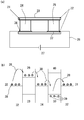
- FIG. 1 is a diagram showing a sample holder according to an embodiment of the present invention.
- FIG. 1A shows a top view of a sample holder according to an embodiment of the present invention.
- 1 (b) shows a sectional view taken along the line BB of FIG. 1 (a)
- FIG. 1 (c) shows a sectional view taken along the line AA of FIG. 1 (a).
- FIG. 2 shows an embodiment of a thermoelectric element applicable to the present invention.
- FIG. 2A shows a cross-sectional view of the Pelche element
- FIG. 2B shows a schematic diagram of the principle of the Pelche element.
- FIG. 3 is a diagram showing a sample holder according to an embodiment of the present invention.
- the sample holder of the present invention is installed close to the sample holder shaft portion having the sample and / or sample mesh mounting portion, the outer cylinder portion capable of storing the sample holder shaft portion, the cooling portion, and the cooling portion. It is characterized by having a thermoelectric element.
- the sample holder shaft portion having the sample and / or the sample mesh mounting portion is not particularly limited, and may have only the sample mounting portion on which the sample is placed.
- the arrangement position of the cooling unit is not particularly limited, but for example, it can be arranged on the handle side of the sample holder.
- the cooling unit it is possible to cool the sample holder shaft, the shielding unit (if any), and the sample by using liquid nitrogen, liquid helium, a solid refrigerant, or the like.
- thermoelectric element installed in the vicinity of the cooling unit.
- the position of the thermoelectric element is not particularly limited as long as it is installed close to the cooling unit.
- the thermoelectric element makes it possible to efficiently set the temperature required for the sample, that is, to control the temperature.
- the thermoelectric element may be arranged so as to be close to the cooling unit.
- a structure may be used in which the cooling unit such as a solid refrigerant is pressed against the heat dissipation surface side, or a gap is provided.
- the structure may be such that it is exposed to cold air.
- cold air When cold air is applied, natural convection or forced convection using a fan or the like may be used, but when forced convection causes vibration, natural convection is desirable, although it depends on the degree of forced convection.
- the refrigerant of the cooling unit is characterized by being composed of a solid refrigerant, a liquid refrigerant, or a gaseous refrigerant.
- the refrigerant may be a solid, a liquid, or a gas.
- the thermoelectric element is characterized by being a thermoelectric element utilizing an effect selected from at least one of the Peltier effect and the Thomson effect.
- the Peltier effect also called the Pelche effect
- the Peltier effect is an effect that converts electrical energy into heat energy, and is a phenomenon in which when two types of dissimilar metals (or semiconductors) are connected at both ends and an electric current is passed through them, a temperature difference occurs at both ends. .. In particular, it is called a Peltier element and is used for cooling precision equipment and wine cellars.
- the Thomson effect is the effect of generating heat other than Joule heat (absorbing heat when the current is reversed), which is generated when a current is passed through a uniform metal (or dissimilar metal) with a temperature gradient. Say that. Both can generate heat or absorb heat.
- the thermoelectric element is a Peltier element from the viewpoint of good cooling / heating response and suppressing the influence of heat drift as much as possible.
- the Peltier element is also called a Pelche element (thermo module), which is a general term for elements that utilize the Pelche effect.
- the structure that is currently considered to have the best performance in the mainstream is called the " ⁇ type" and has the structure shown in FIG.
- FIG. 2 shows an embodiment of a thermoelectric element applicable to the present invention.
- FIG. 2A shows a cross-sectional view of the Pelche element
- FIG. 2B shows a schematic diagram of the principle of the Pelche element.
- 21 is a hot-side metal (mainly Cu)
- 22 is a ceramic substrate (mainly alumina)
- 23 is a heat dissipation surface
- 24 is an N-type semiconductor
- 25 is a P-type semiconductor
- 26 is an electric wire.
- 27 is the power supply
- 28 is the heat absorption
- 29 is the conduction band of the N-type semiconductor
- 30 is the heat dissipation
- 31 is the plus side
- 32 is the heat absorption side
- 33 is the valence band
- 34 is the heat dissipation side
- 35 is the minus side
- 36 is cold.
- Side metal mainly Cu
- 37 is cold side metal (mainly Cu)
- 38 is electron
- 39 is hole
- 40 is the conduction band of P-type semiconductor.
- a negative electrode is connected to the metal 36 on the N-type semiconductor 24 side. Therefore, the voltage pushes electrons from the conduction band of the metal 36 to the conduction band 29 of the N-type semiconductor 24. At this time, since there is an energy gap between the conduction band of the metal 36 and the conduction band 29 of the N-type semiconductor 24, the electrons deprive the metal 36 of heat energy, and as a result, the metal 36 is cooled. Subsequently, electrons flow and fall from the conduction band 29 of the N-type semiconductor 24 to the conduction band of the metal 21. The energy gap between the two bands causes the electrons to emit thermal energy. In this way, the metal 21 on the hot side is heated.
- the flowing electrons fall from the conduction band of the metal 21 into the holes 39 flowing in the P-type semiconductor 25 and release heat energy to heat the metal 21 on the hot side.
- holes 39 are produced by voltage and flow from the cold side 37 to the hot side 21.
- the electrons generated at that time are pushed up to the conduction band of the cold-side metal by the voltage, and take away the heat energy corresponding to those energy gaps to cool the cold-side metal 37.
- the flow of electric current in this way transfers heat from the cold side of the Pelche module to the hot side.
- the semiconductor material is not particularly limited, and any of them can be applied, but Bi-Te semiconductors are considered to have the best performance and are the mainstream.
- the heat radiation side of the thermoelectric element and the cooling unit can be set to a lower temperature by cooling the heat radiation side of the thermoelectric element. It is characterized by contact with.
- cooling is mainly described, but in the present invention, it is also possible to heat by a thermoelectric element.
- thermoelectric element such as the Pelche element
- the practicality also changes depending on the shape of the thermoelectric element such as the Pelche element (whether it is a multi-stage type or not).
- a multi-stage thermoelectric element for example, a Pelche element can be used.
- the forced convection chiller can mean, for example, a chiller that forcibly circulates the refrigerant through the heat dissipation surface.
- a forced convection chiller it is possible to apply a refrigerant with low pulsation and a low temperature of -20 degrees.
- the refrigerant of the cooling unit is a solid refrigerant or a liquid refrigerant from the viewpoint that vibration does not enter due to a low pulsation chiller and complex factors such as the balance of the center of gravity and the weight.
- it is characterized by being composed of a gaseous refrigerant. That is, in the present invention, the heat radiating surface of the Pelche element or the like can be cooled by a solid refrigerant such as dry ice, a liquid refrigerant such as water, or a gas refrigerant using various gases. This makes it possible to eliminate the effects of vibration as much as possible.
- the handle that is, the heat sink of the Pelche
- the heat sink can receive the vibration due to convection, and the vibration can be suppressed.
- the structure is such that an air layer cannot be formed so that bubbles do not enter, and it is possible to adapt to forced convection by suppressing vibration caused by bubbles.
- the cooling gas is not limited to liquid nitrogen. If only the gas is passed through the heat dissipation surface, it is considered that it can be put into practical use with almost no influence of vibration. Therefore, in the present invention, as described above, even when a solid refrigerant is actually used as the cooling unit, it is sufficient to apply cold air with a gap instead of pressing it against the heat radiating surface. In addition, when liquid nitrogen gas is used, the cooling gas is passed through the heat dissipation surface and can be observed without being affected by vibration.
- the heat from the thermoelectric element is transferred to the sample holder shaft. It suffices if the heat from the thermoelectric element can be transferred to the sample holder shaft, for example, the heat from the thermoelectric element can be brought into contact with the sample holder via the member. In a preferred embodiment, the heat from the thermoelectric element can be transferred to the sample holder shaft via the heat conductive portion. Due to the existence of such a heat conductive part, if the thermoelectric element and the sample holder shaft are connected by a heat conductive part made of a heat conductive member, heat from the cooling part can be transferred to the sample holder shaft and eventually to the sample. Is possible.
- the heat conductive portion is not particularly limited as long as it can come into contact with the sample holder shaft so as not to impair the biaxial tilting mechanism of the sample holder shaft.
- the heat conductive portion is not particularly limited as long as it can efficiently conduct heat, and examples thereof include pure copper, copper alloys, and aluminum alloys.
- copper mixed with (STC) carbon any material with good thermal conductivity that can be machined may be used.
- the heat is transferred via a clamp mechanism.
- the heat conductive portion can preferably have a clamping mechanism. This makes it possible to cool the sample with higher performance without damaging the biaxial tilting mechanism of the sample.
- the sample holder shaft portion is characterized by being rotatable.
- the mechanism for making the sample holder shaft portion rotatable is not particularly limited by a conventional method.
- the sample holder shaft portion is connected to a motor or the like, and by rotating the sample holder shaft portion, it can be interlocked with the biaxial tilting mechanism at the tip portion, and the sample can be tilted. be able to.
- the present invention can be applied even in the embodiment including the biaxial tilting mechanism of the sample.
- the sample holder shaft portion is characterized in that it can be moved back and forth.
- the sample holder shaft portion is movable back and forth, that is, the mechanism for making the sample holder shaft portion movable between the center direction of the electron microscope and the so-called handle direction of the sample holder is described. It is not particularly limited by the conventional method.
- the sample holder of the present invention can correspond to the atmosphere non-exposure mechanism.
- the sample holder shaft is driven in the axial direction by connecting the holder handle (handle) and the sample holder shaft, and then pulling the handle backward so that the sample holder shaft can be moved back and forth. Can be stored in. By storing it in the outer cylinder, it is possible to isolate the inside of the holder from the atmosphere.
- the cooling unit is removable. By making it removable, it is possible to easily handle any refrigerant. By changing the cover on the heat dissipation surface, it is possible to easily handle any refrigerant.
- the method of making it removable is not particularly limited, and is based on a conventional method.
- the sample holder main body and the cooling unit are characterized by having an attachment connection portion for switching a refrigerant that connects the sample holder main body and the cooling unit.
- This also makes it possible to handle any refrigerant more easily. That is, by replacing the cooling unit, it is possible to perform water cooling or forced convection of liquid nitrogen vaporized gas, and the merit of forced convection is that the heat dissipation surface can be continuously cooled, which is convenient for long-term observation and analysis. Equipment can be provided.
- the connecting portion is not particularly limited as long as it is possible to connect the sample holder main body and the cooling portion. As for the connection method, it is possible to use a conventional method.
- cooling water is an example, and is not limited to water as long as it is forced convection.
- the refrigerant can be a solid refrigerant, a liquid refrigerant, or a gaseous refrigerant even if the cooling unit is removable.
- FIG. 1 is a diagram showing a sample holder according to an embodiment of the present invention.
- FIG. 1A shows a top view of a sample holder according to an embodiment of the present invention.
- 1 (b) shows a sectional view taken along the line BB of FIG. 1 (a)
- FIG. 1 (c) shows a sectional view taken along the line AA of FIG. 1 (a).
- 1 is an elastic member
- 2 is a heat conductive part
- 3 is a two-axis drive motor
- 4 is a heat sink
- 5 is a cooling part
- 6 is a heat insulating part (heat insulating material)
- 7 is a thermoelectric element (Pelche element).
- 8 indicates a sample holder shaft (biaxial tilting shaft, heat conduction shaft)
- 9 indicates a sample and / or a sample mesh installation portion
- 10 indicates an outer cylinder portion.
- reference numeral 2 denotes a heat conductive portion, which in this example has a clamping mechanism.
- Reference numeral 1 denotes an elastic member such as a spring, which can be appropriately prepared so as not to interfere with the rotation of the sample holder shaft (biaxial tilting shaft, heat conduction shaft) 8 and to provide appropriate thermal contact.
- reference numeral 2 is a heat conductive portion, and in this example, it has a clamping mechanism.
- the clamp mechanism can be appropriately adjusted so as not to interfere with the rotation of the sample holder shaft (biaxial tilt shaft, heat conduction shaft) 8 and to provide appropriate thermal contact.
- Reference numeral 3 is a two-axis drive motor, which is required for observations in which two-axis drive is required.
- 4 is a heat sink, and 5 is a cooling unit.
- liquid nitrogen, liquid helium, a solid refrigerant, or the like can be used in the cooling unit, and the cooling unit is not particularly limited. When more accurate observation is required, a solid refrigerant such as dry ice can be used as the cooling unit.
- Reference numeral 6 is a heat insulating portion (heat insulating material), and 7 is a thermoelectric element, which is a Pelche element in this example.
- the heat (cooling or heating) controlled by the Pelche element can be conducted to the sample holder shaft (biaxially inclined shaft, heat conduction shaft) 8 via the heat conduction portion 2.
- the heat transferred through the heat conductive portion can cool or heat the sample and / or the sample mesh setting portion 9.
- a solid refrigerant dry ice, etc .; -78.5 degrees
- the vibration becomes infinitely zero as compared with the water-cooled Pelche cooling, and stable and high-resolution observation becomes possible. ..
- a heat conductive part such as a heat conduction clamp.
- a solid refrigerant such as dry ice for the heat dissipation surface of the Pelche element, it is suitable in a lower temperature region, for example, at ⁇ 100 ° C.
- FIG. 3 is a diagram showing a sample holder in one embodiment of the present invention in another embodiment.
- 2 is a heat conductive part
- 3 is a biaxial drive motor
- 4 is a heat sink
- 7 is a thermoelectric element (Pelche element)
- 8 is a sample holder shaft (biaxial tilted shaft, heat conductive shaft)
- 9 is a sample.
- 10 is an outer cylinder part
- 50 is a heat sink attachment for a refrigerant
- 51 is a cover for a refrigerant or forced cooling
- 52 is a refrigerant OUT
- 53 is a refrigerant IN.
- reference numeral 2 is a heat conductive portion, and in this example, it has a clamping mechanism.
- the clamp mechanism can be appropriately adjusted so as not to interfere with the rotation of the sample holder shaft (biaxial tilt shaft, heat conduction shaft) 8 and to provide appropriate thermal contact.
- Reference numeral 3 is a two-axis drive motor, which is required for observations in which two-axis drive is required.
- Reference numeral 4 is a heat sink, and the cooling portion is removable in this embodiment.
- the refrigerant used for cooling a solid refrigerant, a liquid refrigerant, or a gaseous refrigerant can be used.
- thermoelectric element 7 is a thermoelectric element, which is a Pelche element in this example.
- the heat (cooling or heating) controlled by the Pelche element can be conducted to the sample holder shaft (biaxially inclined shaft, heat conduction shaft) 8 via the heat conduction portion 2.
- the heat transferred through the heat conductive portion can cool or heat the sample and / or the sample mesh setting portion 9.
- any refrigerant can be used. It was also possible to perform water cooling and forced convection of liquid nitrogen vaporized gas, and it was found that the merit of forced convection is that the heat dissipation surface can be continuously cooled, which is suitable for long-term observation and analysis.
- vibration since vibration is not applied even by forced convection by cooling water, it has been found that the structure is not affected by vibration even by forced convection of cooling water if the structure is such that vibration does not occur even if it is not a solid refrigerant. .. It was also found that forced convection with cooling water is the most efficient and suitable for long-term observation when vibration does not occur. Cooling water is an example, and is not limited to water as long as it is forced convection. Typical examples of the refrigerant include Fluorinert and Garden.
- the Pelche element is placed on the outside of the housing (sample holder) in the same manner as the liquid nitrogen type cooling holder. It was found that it is possible to cool the tip of the sample by heat conduction by arranging it near the handle of the sample. In principle, it is possible to precisely control the temperature in the negative region from around room temperature by controlling the amount of current energized in the Pelche element by creating an endothermic surface and a heat dissipation surface by the movement of electrons. Due to these effects, it was found that it is possible to manufacture a thermoelectric element type sample holder capable of biaxial tilting and stable high-resolution observation, and depending on the refrigerant, stable observation for a long time.
- the sample holder which can be cooled without disturbing the biaxial tilt, contributes to in-situ observation and is applicable in a wide range of technical fields.
Landscapes
- Chemical & Material Sciences (AREA)
- Analytical Chemistry (AREA)
- Sampling And Sample Adjustment (AREA)
Priority Applications (2)
| Application Number | Priority Date | Filing Date | Title |
|---|---|---|---|
| US18/010,119 US20230268157A1 (en) | 2020-07-03 | 2021-06-23 | Specimen holder |
| JP2022533910A JP7668034B2 (ja) | 2020-07-03 | 2021-06-23 | 試料ホルダー |
Applications Claiming Priority (2)
| Application Number | Priority Date | Filing Date | Title |
|---|---|---|---|
| JP2020-115844 | 2020-07-03 | ||
| JP2020115844 | 2020-07-03 |
Publications (1)
| Publication Number | Publication Date |
|---|---|
| WO2022004514A1 true WO2022004514A1 (ja) | 2022-01-06 |
Family
ID=79316275
Family Applications (1)
| Application Number | Title | Priority Date | Filing Date |
|---|---|---|---|
| PCT/JP2021/023735 Ceased WO2022004514A1 (ja) | 2020-07-03 | 2021-06-23 | 試料ホルダー |
Country Status (3)
| Country | Link |
|---|---|
| US (1) | US20230268157A1 (https=) |
| JP (1) | JP7668034B2 (https=) |
| WO (1) | WO2022004514A1 (https=) |
Cited By (1)
| Publication number | Priority date | Publication date | Assignee | Title |
|---|---|---|---|---|
| JP2023054894A (ja) * | 2021-10-05 | 2023-04-17 | 株式会社メルビル | ステージ |
Citations (5)
| Publication number | Priority date | Publication date | Assignee | Title |
|---|---|---|---|---|
| JP2007299753A (ja) * | 2006-05-01 | 2007-11-15 | Fei Co | 温度スイッチを備える粒子−光学装置 |
| JP2008508684A (ja) * | 2004-07-30 | 2008-03-21 | イー エイ フィシオネ インストルメンツ インコーポレーテッド | イオンを利用して材料をミリング処理する装置及び方法 |
| JP2012033335A (ja) * | 2010-07-29 | 2012-02-16 | Hitachi High-Technologies Corp | イオンミリング装置 |
| JP2016085066A (ja) * | 2014-10-23 | 2016-05-19 | 浜松ホトニクス株式会社 | X線像撮像用ユニット及びx線顕微鏡 |
| JP2018129163A (ja) * | 2017-02-08 | 2018-08-16 | 日本電子株式会社 | 試料移動装置及び電子顕微鏡 |
Family Cites Families (5)
| Publication number | Priority date | Publication date | Assignee | Title |
|---|---|---|---|---|
| US5075555A (en) * | 1990-08-10 | 1991-12-24 | Kevex Instruments | Peltier cooled lithium-drifted silicon x-ray spectrometer |
| EP0840940B1 (de) * | 1995-07-25 | 2000-06-14 | Nmi Naturwissenschaftliches Und Medizinisches Intitut An Der Universität Tübingen In Reutlingen | Verfahren und vorrichtung zur ionendünnung in einem hochauflösenden transmissionselektronenmikroskop |
| EP1585999A4 (en) * | 2002-08-02 | 2008-09-17 | E A Fischione Instr Inc | METHOD AND DEVICE FOR PREPARING SAMPLES FOR MICROSCOPY |
| US20060065853A1 (en) * | 2004-09-30 | 2006-03-30 | Chad Rue | Apparatus and method for manipulating sample temperature for focused ion beam processing |
| WO2017073816A1 (ko) * | 2015-10-30 | 2017-05-04 | 한국기초과학지원연구원 | 온도 조절이 가능한 tem 또는 stem용 시료홀더 |
-
2021
- 2021-06-23 JP JP2022533910A patent/JP7668034B2/ja active Active
- 2021-06-23 WO PCT/JP2021/023735 patent/WO2022004514A1/ja not_active Ceased
- 2021-06-23 US US18/010,119 patent/US20230268157A1/en active Pending
Patent Citations (5)
| Publication number | Priority date | Publication date | Assignee | Title |
|---|---|---|---|---|
| JP2008508684A (ja) * | 2004-07-30 | 2008-03-21 | イー エイ フィシオネ インストルメンツ インコーポレーテッド | イオンを利用して材料をミリング処理する装置及び方法 |
| JP2007299753A (ja) * | 2006-05-01 | 2007-11-15 | Fei Co | 温度スイッチを備える粒子−光学装置 |
| JP2012033335A (ja) * | 2010-07-29 | 2012-02-16 | Hitachi High-Technologies Corp | イオンミリング装置 |
| JP2016085066A (ja) * | 2014-10-23 | 2016-05-19 | 浜松ホトニクス株式会社 | X線像撮像用ユニット及びx線顕微鏡 |
| JP2018129163A (ja) * | 2017-02-08 | 2018-08-16 | 日本電子株式会社 | 試料移動装置及び電子顕微鏡 |
Non-Patent Citations (1)
| Title |
|---|
| KITANO SEIKI CO., LTD.: "Pelche type heating / cooling TEM sample holder", IPROS MANUFACTURING, 31 January 2020 (2020-01-31), pages 1 - 7, XP055896153, Retrieved from the Internet <URL:https://www.ipros.jp/product/detail/2000489684> * |
Cited By (2)
| Publication number | Priority date | Publication date | Assignee | Title |
|---|---|---|---|---|
| JP2023054894A (ja) * | 2021-10-05 | 2023-04-17 | 株式会社メルビル | ステージ |
| JP7734404B2 (ja) | 2021-10-05 | 2025-09-05 | 株式会社メルビル | ステージ |
Also Published As
| Publication number | Publication date |
|---|---|
| US20230268157A1 (en) | 2023-08-24 |
| JP7668034B2 (ja) | 2025-04-24 |
| JPWO2022004514A1 (https=) | 2022-01-06 |
Similar Documents
| Publication | Publication Date | Title |
|---|---|---|
| JP3610275B2 (ja) | 半導体製造工程設備用熱電冷却温度調節装置 | |
| US5884485A (en) | Power lead for electrically connecting a superconducting coil to a power supply | |
| US4253515A (en) | Integrated circuit temperature gradient and moisture regulator | |
| Bar-Cohen et al. | On-chip thermal management and hot-spot remediation | |
| US8008571B2 (en) | Thermoelectric composite semiconductor | |
| JP2001059660A (ja) | 混合熱電冷却装置および方法 | |
| JP7291730B2 (ja) | 回動可能なステージ、当該ステージを備える電子顕微鏡、および当該ステージのロータを冷却する方法 | |
| WO2022004514A1 (ja) | 試料ホルダー | |
| WO2025011677A1 (zh) | 无液氦消耗循环制冷系统及液氦温区电子显微镜 | |
| WO2008082678A1 (en) | An indirect method and apparatus for cooling a silicon drift detector | |
| Wang et al. | Enhanced cryogenic thermoelectric cooling of Bi0. 5Sb1. 5Te3 by carrier optimization | |
| TW201029044A (en) | Apparatus for sub-zero temperature ion implantation | |
| JP6279692B1 (ja) | 試料ホルダー | |
| US20070044483A1 (en) | Localized refrigerator apparatus for a thermal management device | |
| JP7723968B2 (ja) | ステージ | |
| JP7734404B2 (ja) | ステージ | |
| JP7844033B2 (ja) | ステージ | |
| JP3377350B2 (ja) | 熱電冷却型パワーリード | |
| JP2018078028A (ja) | 試料ホルダー | |
| Wandelt et al. | Design of a cryo-UHV sample holder with unrestricted manipulation | |
| CN222914725U (zh) | 样品冷却装置及扫描电子显微镜 | |
| KR102147181B1 (ko) | 온도조절장치 및 이를 포함하는 반도체 처리장치 | |
| JPH06260125A (ja) | 試料冷却装置を備えた電子顕微鏡 | |
| JP2025114055A (ja) | 電子顕微鏡の冷却試料ホルダ及びこれを用いた荷電粒子線装置 | |
| KR20170140657A (ko) | 열전소자와 냉매를 이용한 냉온 제어 시스템 |
Legal Events
| Date | Code | Title | Description |
|---|---|---|---|
| 121 | Ep: the epo has been informed by wipo that ep was designated in this application |
Ref document number: 21831802 Country of ref document: EP Kind code of ref document: A1 |
|
| ENP | Entry into the national phase |
Ref document number: 2022533910 Country of ref document: JP Kind code of ref document: A |
|
| NENP | Non-entry into the national phase |
Ref country code: DE |
|
| 122 | Ep: pct application non-entry in european phase |
Ref document number: 21831802 Country of ref document: EP Kind code of ref document: A1 |