WO2022004382A1 - 画像生成装置、画像生成方法、及びプログラム - Google Patents
画像生成装置、画像生成方法、及びプログラム Download PDFInfo
- Publication number
- WO2022004382A1 WO2022004382A1 PCT/JP2021/022846 JP2021022846W WO2022004382A1 WO 2022004382 A1 WO2022004382 A1 WO 2022004382A1 JP 2021022846 W JP2021022846 W JP 2021022846W WO 2022004382 A1 WO2022004382 A1 WO 2022004382A1
- Authority
- WO
- WIPO (PCT)
- Prior art keywords
- viewpoint
- image
- target
- frame
- target viewpoint
- Prior art date
- Legal status (The legal status is an assumption and is not a legal conclusion. Google has not performed a legal analysis and makes no representation as to the accuracy of the status listed.)
- Ceased
Links
Images



Classifications
-
- H—ELECTRICITY
- H04—ELECTRIC COMMUNICATION TECHNIQUE
- H04N—PICTORIAL COMMUNICATION, e.g. TELEVISION
- H04N13/00—Stereoscopic video systems; Multi-view video systems; Details thereof
- H04N13/20—Image signal generators
- H04N13/275—Image signal generators from three-dimensional [3D] object models, e.g. computer-generated stereoscopic image signals
-
- G—PHYSICS
- G06—COMPUTING OR CALCULATING; COUNTING
- G06T—IMAGE DATA PROCESSING OR GENERATION, IN GENERAL
- G06T19/00—Manipulating three-dimensional [3D] models or images for computer graphics
-
- G—PHYSICS
- G06—COMPUTING OR CALCULATING; COUNTING
- G06T—IMAGE DATA PROCESSING OR GENERATION, IN GENERAL
- G06T7/00—Image analysis
- G06T7/20—Analysis of motion
-
- H—ELECTRICITY
- H04—ELECTRIC COMMUNICATION TECHNIQUE
- H04N—PICTORIAL COMMUNICATION, e.g. TELEVISION
- H04N13/00—Stereoscopic video systems; Multi-view video systems; Details thereof
- H04N13/10—Processing, recording or transmission of stereoscopic or multi-view image signals
- H04N13/106—Processing image signals
- H04N13/111—Transformation of image signals corresponding to virtual viewpoints, e.g. spatial image interpolation
- H04N13/117—Transformation of image signals corresponding to virtual viewpoints, e.g. spatial image interpolation the virtual viewpoint locations being selected by the viewers or determined by viewer tracking
-
- H—ELECTRICITY
- H04—ELECTRIC COMMUNICATION TECHNIQUE
- H04N—PICTORIAL COMMUNICATION, e.g. TELEVISION
- H04N13/00—Stereoscopic video systems; Multi-view video systems; Details thereof
- H04N13/20—Image signal generators
- H04N13/204—Image signal generators using stereoscopic image cameras
- H04N13/243—Image signal generators using stereoscopic image cameras using three or more two-dimensional [2D] image sensors
-
- H—ELECTRICITY
- H04—ELECTRIC COMMUNICATION TECHNIQUE
- H04N—PICTORIAL COMMUNICATION, e.g. TELEVISION
- H04N13/00—Stereoscopic video systems; Multi-view video systems; Details thereof
- H04N13/20—Image signal generators
- H04N13/282—Image signal generators for generating image signals corresponding to three or more geometrical viewpoints, e.g. multi-view systems
-
- H—ELECTRICITY
- H04—ELECTRIC COMMUNICATION TECHNIQUE
- H04N—PICTORIAL COMMUNICATION, e.g. TELEVISION
- H04N13/00—Stereoscopic video systems; Multi-view video systems; Details thereof
- H04N13/30—Image reproducers
- H04N13/349—Multi-view displays for displaying three or more geometrical viewpoints without viewer tracking
- H04N13/351—Multi-view displays for displaying three or more geometrical viewpoints without viewer tracking for displaying simultaneously
-
- H—ELECTRICITY
- H04—ELECTRIC COMMUNICATION TECHNIQUE
- H04N—PICTORIAL COMMUNICATION, e.g. TELEVISION
- H04N13/00—Stereoscopic video systems; Multi-view video systems; Details thereof
- H04N13/30—Image reproducers
- H04N13/363—Image reproducers using image projection screens
-
- H—ELECTRICITY
- H04—ELECTRIC COMMUNICATION TECHNIQUE
- H04N—PICTORIAL COMMUNICATION, e.g. TELEVISION
- H04N13/00—Stereoscopic video systems; Multi-view video systems; Details thereof
- H04N13/30—Image reproducers
- H04N13/366—Image reproducers using viewer tracking
- H04N13/376—Image reproducers using viewer tracking for tracking left-right translational head movements, i.e. lateral movements
-
- H—ELECTRICITY
- H04—ELECTRIC COMMUNICATION TECHNIQUE
- H04N—PICTORIAL COMMUNICATION, e.g. TELEVISION
- H04N13/00—Stereoscopic video systems; Multi-view video systems; Details thereof
- H04N13/30—Image reproducers
- H04N13/398—Synchronisation thereof; Control thereof
Definitions
- This technology relates to an image generation device, an image generation method, and a program applicable to the display of multi-viewpoint images.
- Patent Document 1 discloses a technique for updating a background for generating a virtual viewpoint image with high accuracy and with a low processing load. Specifically, in order to reproduce the background in a three-dimensional space, the background shape is divided into partial regions. Then, the input image captured by the camera is divided into the partial regions. The input image divided for each sub-region is compared with the input image for the corresponding sub-region of the immediately preceding frame, and the importance is determined for each sub-region. Based on the determined importance, it is determined whether or not to update the input image for each partial region (paragraphs [0012] [0020] to [0023, etc.] of Patent Document 1).
- an object of the present technology is to provide an image generation device, an image generation method, and a program capable of reducing the processing load required for generating a viewpoint image.
- the image generation device is an image generation device that generates multi-viewpoint image data for displaying a multi-viewpoint image at a predetermined frame rate, and is the first generation.
- a unit, a generation control unit, and a second generation unit are provided.
- the first generation unit can generate a plurality of viewpoint images corresponding to a plurality of viewpoint positions.
- the generation control unit sets one or more target viewpoint positions that are a part of the plurality of viewpoint positions for each frame, and one or more target viewpoints corresponding to the set one or more target viewpoint positions.
- the image is generated by the first generation unit.
- the second generation unit generates the multi-viewpoint image data by using the one or more target viewpoint images generated for each frame.
- one or more target viewpoint images corresponding to one or more target viewpoint positions that are a part of a plurality of viewpoint positions are generated for each frame. Therefore, for each frame, one or more target viewpoint images that are a part of the plurality of viewpoint images are generated. This makes it possible to reduce the processing load required to generate the viewpoint image.
- the second generation unit uses the one or more target viewpoint images generated in a predetermined frame and the one or more target viewpoint images generated in a frame earlier than the predetermined frame.
- the multi-viewpoint image data of the predetermined frame may be generated.
- the generation control unit generates one or more first target viewpoint images corresponding to one or more first target viewpoint positions in the first frame, and the generation control unit generates the first target viewpoint image in the second frame continuous with the first frame.
- One or more second target viewpoint images corresponding to one or more second target viewpoint positions different from any one or more first target viewpoint positions may be generated.
- the second generation unit generates the multi-viewpoint image data of the second frame by using the one or more first target viewpoint images and the one or more second target viewpoint images. May be good.
- the generation control unit sets the number of update frames, and divides the plurality of viewpoint positions into a plurality of target viewpoint position groups having the same number as the number of update frames and in which the target viewpoint positions do not overlap with each other. , Each of the plurality of target viewpoint position groups is assigned to each of the consecutive frames having the number of updated frames, and the target viewpoint image corresponding to the assigned target viewpoint position group is assigned to each of the plurality of frames. You may generate a group.
- the generation control unit sets the number of update frames to 2, and sets the plurality of viewpoint positions to a first target viewpoint position group in which the target viewpoint positions do not overlap with each other and a second target viewpoint position. It is divided into groups, and the first target viewpoint position group and the second target viewpoint position group are assigned to two consecutive frames, and the second one assigned in each of the two frames. A first target viewpoint image group corresponding to the target viewpoint position group 1 and a second target viewpoint image group corresponding to the assigned second target viewpoint position group may be generated.
- the generation control unit may be able to change the number of update frames.
- the generation control unit may change the number of updated frames based on the movement of the object to be displayed or the mode set for the multi-viewpoint image display.
- the generation control unit may set the target viewpoint position of 1 or more based on the interpupillary distance for each frame and generate the target viewpoint image of 1 or more.
- the generation control unit may divide the plurality of viewpoint positions into the plurality of target viewpoint position groups based on the interpupillary distance.
- the second generation unit uses the one or more target viewpoint images generated in a predetermined frame and the multi-viewpoint image data generated in a frame earlier than the predetermined frame.
- the multi-viewpoint image data of the predetermined frame may be generated.
- the first generation unit may generate a virtual image as the viewpoint image.
- the first generation unit may acquire a plurality of captured images as the plurality of viewpoint images from a plurality of image pickup devices arranged at the plurality of viewpoint positions.
- the generation control unit may have the first generation unit output the captured image corresponding to the one or more target viewpoint images and discard the other captured images for each frame.
- the generation control unit may set the target viewpoint position of 1 or more based on the position information of the user for each frame and generate the target viewpoint image of 1 or more.
- the second generation unit may generate the multi-viewpoint image data as data for multi-viewpoint display of the multi-viewpoint display device.
- the multi-viewpoint display device may include a plurality of projectors.
- the second generation unit may generate a plurality of corresponding multi-viewpoint image data corresponding to each of the plurality of projectors as the multi-viewpoint image data.
- the multi-viewpoint display device may include a multi-viewpoint display.
- the second generation unit may generate the multi-viewpoint image data corresponding to the multi-viewpoint display.
- the image generation method is an image generation method executed by a computer system and generating multi-viewpoint image data for displaying a multi-viewpoint image at a predetermined frame rate, and is a plurality of image generation methods for each frame. This includes setting one or more target viewpoint positions that are a part of the viewpoint positions of the above and generating one or more target viewpoint images corresponding to the set one or more target viewpoint positions.
- the multi-viewpoint image data is generated by using the one or more target viewpoint images generated for each frame.
- the program according to one form of the present technology causes a computer system to execute the image generation method.
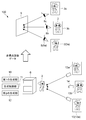
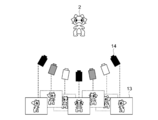
- FIG. 1 is a schematic diagram showing a basic configuration example of an image display system according to an embodiment of the present technology.
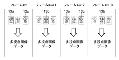
- FIG. 2 is a chart diagram showing a basic operation example of the image display system.
- the image display system 100 includes a multi-viewpoint display device 5 and an image generation device 6.
- the multi-viewpoint display device 5 and the image generation device 6 are communicably connected via wire or wireless.
- the connection form between each device is not limited, and for example, wireless LAN communication such as WiFi and short-range wireless communication such as Bluetooth (registered trademark) can be used.
- the multi-viewpoint display device 5 can display a multi-viewpoint image.
- the multi-viewpoint image is an image capable of displaying the image 3 corresponding to each of the plurality of viewpoint positions 8.
- the user observeer
- An image 3a when the character 2 is viewed from the left side is displayed corresponding to the viewpoint position 8a which is a position moved to the left side from the front viewpoint position 8b with respect to the multi-viewpoint display device 5.
- the multi-viewpoint display device 5 displays a multi-viewpoint image based on the multi-viewpoint image data generated by the image generation device 6. A specific configuration example of the multi-viewpoint display device 5 will be described later.
- the image generation device 6 generates multi-viewpoint image data for displaying a multi-viewpoint image at a predetermined frame rate.
- the image includes both a still image and a moving image (video).
- generating multi-viewpoint image data at a predetermined frame rate corresponds to generating image data of a multi-viewpoint image displayed at a predetermined frame rate. That is, the multi-viewpoint image data includes the image data of the multi-viewpoint image displayed in each frame.
- the image data of the multi-viewpoint image displayed in each frame is described as the multi-viewpoint image data of each frame.
- generating an image at a predetermined frame rate is not limited to generating a moving image (video). This technique can be applied even when an image is displayed in which the frame rate is relatively high and the still image is frame-advanced for the viewer. Of course, such an image display can be regarded as a moving image (video) display.
- the image generation device 6 has hardware necessary for configuring a computer, such as a processor such as a CPU, GPU, and DSP, a memory such as ROM and RAM, and a storage device such as an HDD.
- a processor such as a CPU, GPU, and DSP
- a memory such as ROM and RAM
- a storage device such as an HDD.
- hardware such as FPGA and ASIC may be used (see FIG. 17).
- the image generation method according to the present technology is executed by the processor loading and executing the program according to the present technology recorded in advance in the ROM or the like into the RAM.
- the image generation device 6 can be realized by any computer such as a PC (Personal Computer).
- hardware such as FPGA and ASIC may be used.
- the processor executes a predetermined program
- the first generation unit 10 as a functional block
- the generation control unit 11, and the second generation unit 12 are configured.
- dedicated hardware such as an IC (integrated circuit) may be used.
- the program is installed in the image generator 6 via, for example, various recording media. Alternatively, the program may be installed via the Internet or the like.
- the type of recording medium on which the program is recorded is not limited, and any computer-readable recording medium may be used. For example, any non-transient storage medium readable by a computer may be used.
- the first generation unit 10 can generate a plurality of viewpoint images 13 corresponding to a plurality of viewpoint positions 8.
- the plurality of viewpoint images 13a to 13c correspond to the images 3a to 3c observed from each viewpoint position 8 displayed by the multi-viewpoint display device 5.
- the images 3a to 3c observed by the user from each viewpoint position 8 are also referred to as viewpoint images.
- an image (image data) mainly generated by the first generation unit 10 will be described as a viewpoint image.
- the viewpoint image 13 is generated by CG (computer graphics).
- the virtual camera 14 is arranged around the object to be displayed (character 2 shown in FIG. 1) so as to surround the object.
- a virtual image captured by each virtual camera 14 is generated as a viewpoint image 13.
- the position where the virtual camera 14 is arranged is set corresponding to the viewpoint position 8 defined for the multi-viewpoint display device 5.
- the viewpoint position 8 at which the user can observe the object at different angles is defined based on the position where the virtual camera 14 is arranged.
- the generation of the viewpoint image 13 by the first generation unit 10 can be said to be the rendering of the viewpoint image 13.
- the viewpoint image 13 can also be called a rendered image.
- the number of viewpoint positions 8 is not limited and can be set arbitrarily. By setting a large number of viewpoint positions 8, it is possible to observe the character 2 from various angles, and it is possible to provide a high-quality viewing experience.
- the generation control unit 11 controls the generation of a plurality of viewpoint images 13 by the first generation unit 10.
- the generation control unit 11 sets one or more target viewpoint positions that are a part of the plurality of viewpoint positions 8 for each frame. Further, the generation control unit 11 causes the first generation unit 10 to generate one or more target viewpoint images corresponding to the set one or more target viewpoint positions. That is, the generation control unit 11 determines which viewpoint image 13 is generated for each frame. The viewpoint image 13 generated in each frame based on the determination becomes the target viewpoint image.
- the viewpoint positions 8a and 8c that are a part of the three viewpoint positions 8a to 8c are the target viewpoint positions for which the viewpoint image 13 is generated. Is set as. Then, the viewpoint images 13a and 13c corresponding to the viewpoint positions 8a and 8c are generated as the target viewpoint images.
- the viewpoint positions 8b, which are a part of the three viewpoint positions 8a to 8c are set as the target viewpoint positions to be generated by the viewpoint image 13. Then, the viewpoint image 13b corresponding to the viewpoint position 8b is generated as the target viewpoint image.
- the viewpoint images 13 corresponding to all the viewpoint positions 8 are not generated for each frame, but one or more target viewpoint images corresponding to a part of one or more target viewpoint positions are generated. To. That is, for each frame, not all the viewpoint images 13 but a part of one or more target viewpoint images are generated. For each frame, which viewpoint position 8 is set to one or more target viewpoint positions is not limited and may be arbitrarily set.
- the second generation unit 12 generates multi-viewpoint image data using one or more target viewpoint images generated for each frame.
- the second generation unit 12 generates multi-viewpoint image data for each frame.
- the multi-viewpoint image data is generated as data for multi-viewpoint display of the multi-viewpoint display device 5. Therefore, the multi-viewpoint image data is generated according to the configuration of the multi-viewpoint display device 5 and the multi-viewpoint display method.
- a plurality of viewpoint images 13 generated by the first generation unit 10 are appropriately converted to generate multi-view image data according to the configuration of the multi-view display device 5 and the multi-view display method.
- the second generation unit 12 generates multi-viewpoint image data using one or more target viewpoint images generated for each frame.
- the processing using the image data is not limited to the processing using only the image data. At least arbitrary processing using the image data is included.
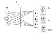
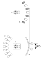
- the multi-viewpoint display device 5 shown in FIG. 3 has a plurality of projectors 16 and a light ray control element 17. Each of the plurality of projectors 16 can project an image, and is configured as a projector array. In the multi-viewpoint display device 5 illustrated in FIG. 3, the five projectors 16 and the light ray control element 17 can display the images 3a to 3c corresponding to the three viewpoint positions 8a to 8c, respectively.
- the specific configuration of the projector 16 is not limited, and any configuration may be adopted.
- the transmission type anisotropic diffusion screen has, for example, anisotropic diffusion characteristics in which the degree of diffusion differs between the horizontal direction and the vertical direction.
- the degree of diffusion in the horizontal direction is set to be smaller than that in the vertical direction, and is configured to have a narrow diffusion characteristic with respect to the horizontal direction.
- the specific configuration of the anisotropic diffusion screen is not limited, and for example, a lens diffusion plate composed of a microlens array or the like, a transmission type HOE (Holographic Optical Element), or the like can be used as the anisotropic diffusion screen. It is possible.
- the viewpoint images 13a to 13b corresponding to each of the three viewpoint positions 8a to 8c are divided into a plurality of strip-shaped regions along the lateral direction of the image.
- the image of the divided area is referred to as a strip image 18.
- the divided strip images 18 are appropriately rearranged to generate image data of the projected image 19 projected from each projector 16.
- the projected image 19 is projected by each projector 16 based on the image data. Therefore, a projection image 19 including strip images 18 of different viewpoint images 13 is projected from a certain projector 16. Further, the projection image 19 including only one strip image 18 may be projected from the other projector 16.
- the user visually recognizes an image 3 in which the strip images 18 corresponding to the viewpoint positions 8 of the projected images 19 projected from different projectors 16 are combined.
- multi-viewpoint image display is realized.
- the image data and the image displayed based on the image data may be described using the same drawing.
- the projected image 19 shown in FIG. 4 may be described as image data of the projected image 19.
- the second generation unit 12 executes rearrangement of the strip image 18 of each viewpoint image 13 to generate multi-viewpoint image data.
- the strip image 18 is rearranged to generate image data of the projected image 19 corresponding to each of the plurality of projectors 16.
- a plurality of image data corresponding to each of the plurality of projectors 16 are generated as multi-viewpoint image data.
- the plurality of image data corresponding to each of the plurality of projectors 16 corresponds to the plurality of corresponding multi-viewpoint image data corresponding to each of the plurality of projectors 16.
- the rearrangement of the strip image 18 can be realized by using a well-known technique based on, for example, the number of projectors 16 and the number of viewpoint positions 8.
- the multi-viewpoint display device 5 shown in FIG. 5 has a multi-viewpoint display 21.
- the multi-viewpoint display 21 makes it possible to simultaneously display images 3 corresponding to a plurality of viewpoint positions 8 toward each viewpoint position 8.
- the multi-viewpoint display 21 can be configured by, for example, any one of a lenticular lens system, a lens array system, and a parallax barrier system. Of course, it is not limited to these methods.
- the multi-viewpoint display 21 shown in FIG. 5 has a flat display panel 22 and a lenticular lens 23.
- the flat display panel 22 has a plurality of pixels arranged in the horizontal direction and the vertical direction.
- the lenticular lens 23 is arranged along the vertical direction.
- the viewpoint images 13a to 13c corresponding to each of the three viewpoint positions 8a to 8c are divided into a plurality of strip images 18 along the lateral direction of the image.
- the divided strip images 18 are appropriately rearranged to generate image data of the display image displayed by the flat display panel 22.
- a display image is displayed by the flat display panel 22 based on the image data. As shown in FIG.
- the pixel region facing the four convex portions 23a of the lenticular lens 23 is divided into three regions 24a to 24c along the horizontal direction.
- the strip image 18 of the three viewpoint images 13 is assigned to the area divided into three.
- the second generation unit 12 executes rearrangement of the strip image 18 of each viewpoint image 13 to generate multi-viewpoint image data.
- the multi-viewpoint image data is multi-viewpoint image data corresponding to the multi-viewpoint display 21.
- the rearrangement of the strip image 18 can be realized by using a well-known technique based on, for example, the configuration of the multi-viewpoint display 21. Compared with the configuration using the projector array, the configuration using the multi-viewpoint display 21 makes it possible to design the entire device more compactly.
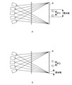
- FIG. 6 is a diagram for explaining the display of a stereoscopic image.
- the width (range) in which the same image 3 (same viewpoint image) can be observed is defined as the viewpoint width.
- the viewpoint width is larger than the interpupillary distance (IPD)
- IPD interpupillary distance
- the parallax image can be displayed as the image 3 (viewpoint image) corresponding to the viewpoint position 8.
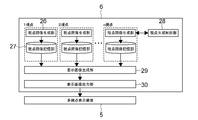
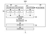
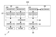
- FIG. 7 is a schematic diagram showing a functional configuration example of the image generation device 6.
- the image generation device 6 includes a plurality of viewpoint image generation units 26, a plurality of viewpoint image storage units 27, a viewpoint image generation control unit 28, a display image generation unit 29, and a display image output unit 30.
- the plurality of viewpoint image generation units 26, viewpoint image generation control unit 28, display image generation unit 29, and display image output unit 30 are configured by, for example, a processor executing a predetermined program. Of course, in order to realize these functional blocks, dedicated hardware such as an IC (integrated circuit) may be used.
- the plurality of viewpoint image storage units 27 are realized by, for example, an HDD, a flash memory, another solid-state memory, or the like. Any storage device may be used without limitation.
- the plurality of viewpoint image generation units 26 are configured to correspond to the plurality of viewpoint positions 8. That is, one viewpoint image generation unit 26 is configured for one viewpoint position 8. Therefore, the plurality of viewpoint image generation units 26 are configured by the number of viewpoint positions 8. In the present embodiment, it is assumed that n viewpoint positions 8 from one viewpoint to n viewpoints are defined as the viewpoint positions 8. Therefore, n viewpoint image generation units 26 are configured. The n viewpoint image generation units 26 generate viewpoint images 13 corresponding to each of the n viewpoint positions 8.
- the plurality of viewpoint image storage units 27 are configured corresponding to the plurality of viewpoint image generation units 26. That is, one viewpoint image storage unit 27 is configured for one viewpoint image generation unit 26. Therefore, n viewpoint image storage units 27, which are the same as the number of viewpoint positions 8, are configured. As shown by the broken line in FIG. 7, it can be said that a pair of the viewpoint image generation unit 26 and the viewpoint image storage unit 27 is configured for one viewpoint position 8.
- the n viewpoint image storage units 27 store the viewpoint images 13 generated by the paired viewpoint image generation units 26.
- the viewpoint image generation control unit 28 controls the generation of the viewpoint image 13 by each viewpoint image generation unit 26 for each frame. Specifically, the viewpoint image generation control unit 28 sets one or more target viewpoint positions that are a part of the plurality of viewpoint positions 8 for each frame. Further, the viewpoint image generation control unit 28 causes the viewpoint image generation unit 26 to generate one or more target viewpoint images corresponding to the set one or more target viewpoint positions. Therefore, the viewpoint image generation control unit 28 determines which viewpoint image 13 is generated for each frame. The viewpoint image 13 generated in each frame based on the determination becomes the target viewpoint image.
- FIG. 8 is a schematic diagram for explaining a setting example of one or more target viewpoint positions.
- the number of updated frames is set by the viewpoint image generation control unit 28.
- the number of updated frames is the number of frames required for updating all the viewpoint images 13.
- the number of updated frames is the number of frames allocated for updating all viewpoint images 13.
- all the viewpoint images 13 are updated over a continuous number of updated frames.
- the number of update frames is set to l. Then, all the viewpoint images 13 are updated by l consecutive frames (# m + 1) to (# m + l).
- the viewpoint image generation control unit 28 divides the plurality of viewpoint positions 8 into a plurality of target viewpoint position groups in which the target viewpoint positions do not overlap with each other, which is the same number as the number of updated frames.
- l target viewpoint position groups (# 1) to (# l) are set.
- the target viewpoint positions included in each target viewpoint position group are set so as not to overlap each other. Therefore, the number of update frames is equal to or less than the total number of viewpoint positions 8.
- the target viewpoint image group (# 3) is a group of target viewpoint images corresponding to each target viewpoint position included in a plurality of target viewpoint position groups (# 3) assigned to the frame (# m + 3).
- all the viewpoint images 13 are updated in one consecutive frame (# m + 1) to (# m + l). Further, by repeating the processing of consecutive frames (# m + 1) to (# m + l), the updating of all the viewpoint images 13 is also repeated. How to set the number of update frames and the target viewpoint position group is not limited, and may be set arbitrarily.
- the odd-numbered frame and the even-numbered frames that follow it are referred to as frames (# m + 1) and (# m + 2).
- indexes 1 to P are added in order from the end. That is, each viewpoint position is identified by a name such as the first viewpoint position 8 or the P-th viewpoint position.
- the method of identifying the viewpoint position 8 such as the method of adding an index is not limited.
- the P viewpoint positions 8 are divided into a target viewpoint position group (# 1) consisting of odd-numbered viewpoint positions 8 and a target viewpoint position group (# 2) consisting of even-numbered viewpoint positions 8.
- every other viewpoint is set so as to be included in a different target viewpoint position group.
- the target viewpoint position group (# 1) and the target viewpoint position group (# 2) are assigned to two consecutive frames (# m + 1) and (# m + 2). Then, in each of the two frames (# m + 1) and (# m + 2), the target viewpoint image group (# 1) corresponding to the assigned target viewpoint position group (# 1) and the assigned target viewpoint position group.
- the target viewpoint image group (# 2) corresponding to (# 2) is generated. In this way, the update of all the viewpoint images 13 may be executed every two frames.
- the target viewpoint position groups (# 1) and (# 2) are one of the first target viewpoint position group and the second target viewpoint position group in which the target viewpoint positions do not overlap with each other. It becomes an embodiment. Further, the target viewpoint image group (# 1) and the target viewpoint image group (# 2) are the first target viewpoint image group corresponding to the assigned first target viewpoint position group and the assigned second target viewpoint image group. It is an embodiment of the second target viewpoint image group corresponding to the position group.
- the present invention is not limited to this, and three target viewpoint position groups may be assigned to three consecutive frames, and three target viewpoint image groups may be repeatedly generated.
- the display image generation unit 29 reads out the viewpoint image 13 corresponding to each viewpoint position 8 from the n viewpoint image storage units 27, and generates multi-view image data. For example, as described with reference to FIGS. 4 and 5, rearrangement of the strip image 18 in which the viewpoint image 13 is divided is executed, and multi-viewpoint image data is generated. As shown in FIG. 7, the multi-viewpoint image data can also be referred to as a display image (display image data).
- the multi-viewpoint image data of the frame (# m + l) is generated by using the target viewpoint image group (# 1 to # l-1) generated in the above.
- the frame (# m + l) is an embodiment of a predetermined frame according to the present technology.
- each target viewpoint image group corresponds to one or more target viewpoints.
- the target viewpoint image group (one or more target viewpoint images) generated in the frame and the target viewpoint image group generated in a frame earlier than the frame. (One or more target viewpoint images) is used to generate multi-view image data of the frame.
- the display image output unit 30 outputs the multi-viewpoint image data generated for each frame to the multi-viewpoint display device 5.
- the first generation unit 10 shown in FIG. 1 is realized by the plurality of viewpoint image generation units 26.
- the viewpoint image generation control unit 28 realizes the generation control unit 11 shown in FIG.
- the display image generation unit 29 realizes the second generation unit 12 shown in FIG.
- the viewpoint image generation control unit 28 may not be configured, and each viewpoint image generation unit 26 may determine whether or not to generate the viewpoint image 13 for each frame.
- the plurality of viewpoint image generation units 26 also function as the generation control unit 11 shown in FIG.
- two consecutive frames are arbitrarily selected from the continuous frames (# m + 1) to (# m + l). Then, of the two consecutive frames, the front frame is the first frame and the rear frame is the second frame. Further, the target viewpoint position group assigned to the first frame is defined as one or more first target viewpoint positions. The target viewpoint position group assigned to the second frame is defined as one or more second target viewpoint positions. Further, the target viewpoint image corresponding to one or more first target viewpoint positions is defined as one or more first target viewpoint images. The target viewpoint image corresponding to one or more second target viewpoint positions is defined as one or more second target viewpoint images.
- the viewpoint image generation control unit 28 generates one or more first target viewpoint images corresponding to one or more first target viewpoint positions in the first frame, and the second frame is continuous with the first frame. In the frame of, one or more second target viewpoint images corresponding to one or more second target viewpoint positions different from any of one or more first target viewpoint positions are generated. Further, the display image generation unit 29 generates multi-viewpoint image data of the second frame by using one or more first target viewpoint images and one or more second target viewpoint images.
- duplication of target viewpoint positions may be allowed for each of the plurality of target viewpoint position groups shown in FIG.
- duplication of target viewpoint positions is allowed between one or more first target viewpoint positions assigned to the first frame and one or more second target viewpoint positions assigned to the second frame. May be good.
- the image generation method executed by the image generation apparatus according to the present technology is not limited to the case where the processing of frames (# m + 1) to (# m + l) is repeated, for example, as shown in FIG. For example, for two consecutive frames, the above-mentioned processing in which these frames are used as the first frame and the second frame is executed at least once. Then, the multi-viewpoint image data of the second frame is generated by using one or more first target viewpoint images and one or more second target viewpoint images. Such processing is also included in one embodiment of the image generation method executed by the image generation apparatus according to the present technology. Furthermore, the process of generating one or more target viewpoint images, which are some viewpoint images 13 instead of all the viewpoint images 13, is executed in at least one frame, and one or more target viewpoint images generated. If the multi-viewpoint image data is generated based on the above, it is included in one embodiment of the image generation method executed by the image generation device according to the present technology.
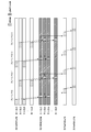
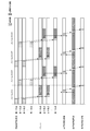
- FIG. 9 is a chart diagram showing an example of generating multi-viewpoint image data.
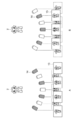
- FIG. 10 is a schematic diagram for explaining the generation of multi-viewpoint image data.
- the viewpoint image generation unit 26 generates one or more target viewpoint images corresponding to one or more target viewpoint positions which are odd-numbered viewpoint positions 8 in a frame (#m) which is an odd frame, and a viewpoint image storage unit 26. It is stored in 27.
- the viewpoint image 13 corresponding to the even-numbered viewpoint position 8 is not generated.
- the first, third, fifth, and seventh viewpoint positions 8 are set as the target viewpoint positions.
- a virtual image (viewpoint image 13) of the character 2 captured by the virtual camera 14 arranged at a position corresponding to the viewpoint position 8 is generated as a target viewpoint image.
- the display image generation unit 29 reads out the viewpoint image 13 corresponding to all the viewpoint positions 8 from all the viewpoint image storage units 27. For the odd-numbered viewpoint position 8, one or more target viewpoint images generated in the frame (#m) are read out. For the even-numbered viewpoint position 8, one or more target viewpoint images generated in the even-numbered frame (# m-1) immediately before the frame (#m) is read out. Multi-viewpoint image data is generated based on all the viewpoint images 13 read out. The generated multi-viewpoint image data is output to the multi-viewpoint display device 5 by the display image output unit 30.
- one or more target viewpoint images corresponding to one or more target viewpoint positions which are even-numbered viewpoint positions 8 are generated and stored in the viewpoint image storage unit 27.
- the viewpoint image 13 corresponding to the odd-numbered viewpoint position 8 is not generated.
- the second, fourth, and sixth viewpoint positions 8 are the target viewpoint positions.
- a virtual image (viewpoint image 13) of the character 2 captured by the virtual camera 14 arranged at a position corresponding to the viewpoint position 8 is generated as a target viewpoint image.
- the display image generation unit 29 reads out the viewpoint image 13 corresponding to all the viewpoint positions 8 from all the viewpoint image storage units 27. For the even-numbered viewpoint position 8, one or more target viewpoint images generated in the frame (# m + 1) are read out. For the odd-numbered viewpoint position 8, one or more target viewpoint images generated in the odd-numbered frame (# m) immediately before the frame (# m + 1), which is a frame earlier than the frame (# m + 1), are read out. Multi-viewpoint image data is generated based on all the viewpoint images 13 read out. The generated multi-viewpoint image data is output to the multi-viewpoint display device 5 by the display image output unit 30.
- one or more target viewpoint images corresponding to one or more target viewpoint positions that are a part of the plurality of viewpoint positions 8 are generated for each frame. Therefore, for each frame, one or more target viewpoint images that are a part of the plurality of viewpoint images 13 are generated. This makes it possible to reduce the processing load required to generate the viewpoint image 13.
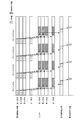
- FIG. 11 is a chart diagram showing the generation of multi-viewpoint image data given as a comparative example.
- the viewpoint image 13 corresponding to all the viewpoint positions 8 is generated in each frame.
- the generated viewpoint image 13 is temporarily stored in a buffer and used by the display image generation unit to generate multi-view image data.
- the load (rendering load) for generating the viewpoint image 13 increases.
- the amount of data handled in each frame increases, and the display frame rate of the multi-viewpoint image decreases.
- the rendering load is further increased and the display frame rate is further reduced. Therefore, it is necessary to reduce the quality of the image such as lowering the resolution of the image, and it is difficult to realize a high-quality multi-viewpoint display.
- the number of viewpoint images 13 acquired for each frame is suppressed, and all the viewpoint images 13 are sequentially updated for each of a plurality of frames.
- the cost (rendering load) required to generate the viewpoint image 13 per frame can be sufficiently suppressed, and the amount of data to be handled can be sufficiently suppressed.
- the number of update frames is a parameter that determines the interval (cycle) in which all viewpoint images 13 are updated. Therefore, the setting of the number of update frames corresponds to the setting of the update cycle.
- the number of updated frames may be arbitrarily changed by the viewpoint image generation control unit 28. As the number of updated frames increases, the processing load per frame decreases, but the acquisition timing of each viewpoint image 13 shifts, so that a moving object may feel uncomfortable.
- the viewpoint image generation control unit 28 can arbitrarily change the number of updated frames based on the movement of the object to be displayed. This makes it possible to balance the processing load and the motion shift, which are in the trade-off relationship described above. For example, when the movement of the object is fast or large, the number of update frames is reduced, and all the viewpoint images 13 are updated in a short update cycle. If the operation of the display object is slow or the change is small, the number of update frames is increased to lengthen the update cycle for updating all the viewpoint images 13. In this way, by making the update cycle (that is, the number of update frames) variable according to the movement of the object, it is possible to reduce the processing load while reducing the perception of the deviation of the object.
- the update cycle of the viewpoint image 13 may be determined according to the mode set by the user.
- the mode is a mode related to multi-viewpoint image display, and is arbitrary, for example, a mode that prioritizes the performance of multi-viewpoint image display (high quality display mode, etc.), a mode that prioritizes low load (low power consumption mode, etc.), and the like. Modes can be adopted. For example, when the user selects a mode in which performance is prioritized, the probability that the movement of the object is deviated can be reduced by shortening the update interval. Further, when the mode in which the low load is prioritized is selected, the processing load can be reduced by lengthening the update interval.
- the update cycle (number of update frames) may be set based on the state of the user acquired by camera tracking or the like.
- the number of update frames may be fixed to a preset constant.
- the interpupillary distance (IPD) may be used as to which viewpoint position 8 is set as one or more target viewpoint positions for each frame. That is, one or more target viewpoint positions may be set for each frame based on the interpupillary distance (IPD), and one or more target viewpoint images may be generated.
- a plurality of viewpoint positions may be divided into a plurality of target viewpoint position groups based on the interpupillary distance (IPD). For example, as illustrated in FIG. 13, the group of virtual cameras 14 of the viewpoint image 13 acquired in a single frame, that is, the group of the target viewpoint position is the user's assumed interpupillary distance (IPD) at the observation position. ) May be determined.
- the interpupillary distance (IPD) may be set to a predetermined value, or a value acquired by using camera tracking or the like may be used.
- IPD interpupillary distance
- the viewpoint image 13 updated at the same timing can be seen by the left and right eyes of the user, so that it is difficult to perceive the deviation of the movement of the object.
- this process is applied when displaying the stereoscopic image shown in FIG. 6B.
- the right-eye image and the left-eye image are updated at the same timing, so that high-quality stereoscopic display is realized.
- FIG. 14 is a schematic diagram showing a functional configuration example of the image generator according to another embodiment.
- FIG. 15 is a chart diagram showing an example of generating multi-viewpoint image data.
- a plurality of buffers 32 are configured instead of the plurality of viewpoint image storage units 27.
- the display image storage unit 33 is configured.
- one or more target viewpoint images corresponding to one or more target viewpoint positions are generated in each frame and temporarily stored in the buffer 32. Further, in the present embodiment, the multi-viewpoint image data (display image) generated by the display image generation unit 29 is stored in the display image storage unit 33 in each frame.
- the display image generation unit 29 reads out one or more target viewpoint images temporarily stored in the buffer 32 in each frame. Further, the display image generation unit 29 reads out the multi-viewpoint image data generated in the past frame from the display image storage unit 33. Then, the display image generation unit 29 generates multi-viewpoint image data by using one or more target viewpoint images of the current frame and the multi-viewpoint image data of the past frame. As described above, in the present embodiment, one or more target viewpoint images generated in a predetermined frame and multi-viewpoint image data generated in a frame earlier than the predetermined frame are used to form a predetermined frame. Multi-viewpoint image data is generated.
- the display image after the strip image 18 is rearranged is stored and held instead of storing and holding the viewpoint image 13. You may.
- the display image generation unit 29 loads the display image after the rearrangement of the previous frame, and rearranges and updates only the corresponding portion of the acquired viewpoint image 13.
- the display image generated by the update is generated as the final multi-viewpoint image data.
- FIG. 16 is a schematic diagram showing a functional configuration example of the image generator according to another embodiment.
- a plurality of display image output units 35 are configured.
- the image generation device 306 is connected to a plurality of display devices 36.
- a plurality of display image output units 35 are configured according to the number of the plurality of display devices 36. Then, a plurality of display image output units 35 are connected to each of the plurality of display devices 36.
- the efficiency of multi-view display is achieved by making the display image output unit 35 correspond to the display device 36 on a one-to-one basis. Is improved.
- a real image may be acquired using a camera array as a real object instead of the camera 14.
- a camera array may be installed in the real space to generate the viewpoint image 13 from an object in the real space.
- the method for suppressing the generation of the viewpoint image 13 according to the present technology can be similarly applied.
- the first generation unit 10 acquires a plurality of captured images as a plurality of viewpoint images 13 from a plurality of image pickup devices arranged at a plurality of viewpoint positions 8.
- the generation control unit 11 causes the first generation unit 10 to output the captured image corresponding to one or more target viewpoint images and discard the other captured images for each frame.
- the output of the captured image by the first generation unit 10 corresponds to the generation of the target viewpoint image by the first generation unit 10.
- the output of the captured image by the first generation unit 10 corresponds to the generation of the target viewpoint image by the first generation unit 10.
- not only CG but also a real object can be displayed on the multi-viewpoint display device 5.
- the user's position information may be used as to which viewpoint position 8 is set as one or more target viewpoint positions for each frame. That is, one or more target viewpoint positions may be set based on the user's position information, and one or more target viewpoint images may be generated.
- the method of acquiring the user's position information is not limited, and any method such as camera tracking may be used. Further, the user's position information may be estimated by machine learning. If the generation position of the viewpoint image is limited to the observer position, the image cannot be observed at other positions, but the generated viewpoint image 13 can be significantly reduced, so that the processing load can be reduced and the display frame rate can be improved. It will be possible to realize. Instead of / in addition to the user's position information, the user's line-of-sight information or the like may be used.
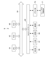
- FIG. 17 is a block diagram showing a hardware configuration example of the image generation device 6.
- the image generation device 6 includes a CPU 61, a ROM (Read Only Memory) 62, a RAM 63, an input / output interface 65, and a bus 64 connecting these to each other.
- a display unit 66, an input unit 67, a storage unit 68, a communication unit 69, a drive unit 70, and the like are connected to the input / output interface 65.
- the display unit 66 is a display device using, for example, a liquid crystal display, an EL, or the like.
- the input unit 67 is, for example, a keyboard, a pointing device, a touch panel, or other operation device.
- the input unit 67 includes a touch panel
- the touch panel may be integrated with the display unit 66.
- the storage unit 68 is a non-volatile storage device, for example, an HDD, a flash memory, or other solid-state memory.
- the drive unit 70 is a device capable of driving a removable recording medium 71 such as an optical recording medium or a magnetic recording tape.
- the communication unit 69 is a modem, a router, or other communication device for communicating with another device that can be connected to a LAN, WAN, or the like.
- the communication unit 69 may communicate using either wired or wireless.
- the communication unit 69 is often used separately from the image generation device 6.
- Information processing (image generation) by the image generation device 6 having the hardware configuration as described above is realized by the cooperation between the software stored in the storage unit 68 or the ROM 62 or the like and the hardware resources of the image generation device 6.
- the information processing method (image generation method) according to the present technology is realized by loading the program constituting the software stored in the ROM 62 or the like into the RAM 63 and executing the program.
- the program is installed in the image generator 6 via, for example, a recording medium 61.
- the program may be installed in the image generator 6 via a global network or the like.
- any non-transient storage medium that can be read by a computer may be used.
- An image generation method and a program according to the present technology may be executed by cooperation of a plurality of computers connected so as to be communicable via a network or the like, and an image generation device according to the present technology may be constructed. That is, the image generation method and the program according to the present technology can be executed not only in a computer system composed of a single computer but also in a computer system in which a plurality of computers operate in conjunction with each other.
- the system means a set of a plurality of components (devices, modules (parts), etc.), and it does not matter whether or not all the components are in the same housing.
- a plurality of devices housed in separate housings and connected via a network, and one device in which a plurality of modules are housed in one housing are both systems.
- the image generation method and program execution according to the present technology by a computer system are, for example, when the generation of a viewpoint image, the setting of a target viewpoint position, the generation of multi-view image data, etc. are executed by a single computer, and each Includes both when the process is performed by different computers. Further, the execution of each process by a predetermined computer includes having another computer execute a part or all of the process and acquiring the result. That is, the image generation method and program according to the present technology can be applied to a cloud computing configuration in which one function is shared by a plurality of devices via a network and jointly processed.
- expressions using "more” such as “greater than A” and “less than A” include both the concept including the case equivalent to A and the concept not including the case equivalent to A. It is an expression that includes the concept. For example, “greater than A” is not limited to the case where the equivalent of A is not included, and “greater than or equal to A” is also included. Further, “less than A” is not limited to “less than A” and includes “less than or equal to A”. When implementing this technique, specific settings and the like may be appropriately adopted from the concepts included in “greater than A” and “less than A” so that the effects described above can be exhibited.
- An image generator that generates multi-view image data for displaying a multi-view image at a predetermined frame rate.
- a first generator that can generate multiple viewpoint images corresponding to multiple viewpoint positions, For each frame, one or more target viewpoint positions that are a part of the plurality of viewpoint positions are set, and one or more target viewpoint images corresponding to the set one or more target viewpoint positions are obtained by the first.
- the generation control unit to be generated by the generation unit of An image generation device including a second generation unit that generates the multi-viewpoint image data using the one or more target viewpoint images generated for each frame.
- the second generation unit uses the one or more target viewpoint images generated in a predetermined frame and the one or more target viewpoint images generated in a frame earlier than the predetermined frame.
- An image generator that generates the multi-viewpoint image data of the predetermined frame.
- the generation control unit Generate one or more first target viewpoint images corresponding to one or more first target viewpoint positions in the first frame.
- Image generator to let you.
- (4) The image generator according to (3).
- the second generation unit is an image that generates the multi-viewpoint image data of the second frame by using the one or more first target viewpoint images and the one or more second target viewpoint images.
- Generator. (5) The image generator according to any one of (1) to (4).
- the generation control unit Set the number of update frames and The plurality of viewpoint positions are divided into a plurality of target viewpoint position groups having the same number as the number of updated frames and in which the target viewpoint positions do not overlap with each other.
- Each of the plurality of target viewpoint position groups is assigned to each of the consecutive frames having the number of updated frames, and the target viewpoint image group corresponding to the assigned target viewpoint position group is assigned to each of the plurality of frames.
- (6) The image generator according to (5).
- the generation control unit Set the number of update frames to 2 and set it to 2.
- the plurality of viewpoint positions are divided into a first target viewpoint position group and a second target viewpoint position group in which the target viewpoint positions do not overlap with each other.
- the first target viewpoint position group and the second target viewpoint position group are assigned to two consecutive frames, and the first target viewpoint position group assigned to each of the two frames is assigned.
- An image generation device that generates a first target viewpoint image group corresponding to the above and a second target viewpoint image group corresponding to the assigned second target viewpoint position group.
- the generation control unit is an image generation device capable of changing the number of update frames.
- the generation control unit is an image generation device that changes the number of updated frames based on the movement of an object to be displayed or a mode set for the multi-viewpoint image display.
- the image generator according to any one of (1) to (8).
- the generation control unit is an image generation device that sets one or more target viewpoint positions based on the interpupillary distance for each frame and generates one or more target viewpoint images.
- the generation control unit is an image display device that divides the plurality of viewpoint positions into the plurality of target viewpoint position groups based on the interpupillary distance. (11)
- the second generation unit uses the one or more target viewpoint images generated in a predetermined frame and the multi-viewpoint image data generated in a frame earlier than the predetermined frame.
- An image generation device that generates the multi-viewpoint image data of the predetermined frame.
- the first generation unit is an image generation device that generates a virtual image as the viewpoint image.
- the first generation unit acquires a plurality of captured images as the plurality of viewpoint images from a plurality of image pickup devices arranged at the plurality of viewpoint positions.
- the generation control unit is an image generation device that causes the first generation unit to output an captured image corresponding to the one or more target viewpoint images and discard other captured images for each frame.
- the image generator according to (1) is an image generation device that causes the first generation unit to output an captured image corresponding to the one or more target viewpoint images and discard other captured images for each frame.
- the generation control unit is an image generation device that sets the one or more target viewpoint positions based on the user's position information for each frame and generates the one or more target viewpoint images.
- the second generation unit is an image generation device that generates the multi-viewpoint image data as data for multi-viewpoint display of the multi-viewpoint display device.
- the multi-view display device includes a plurality of projectors and includes a plurality of projectors.
- the second generation unit is an image generation device that generates a plurality of corresponding multi-viewpoint image data corresponding to each of the plurality of projectors as the multi-viewpoint image data.
- the multi-view display device includes a multi-view display.
- the second generation unit is an image generation device that generates the multi-viewpoint image data corresponding to the multi-viewpoint display.
- the image generation method is For each frame, one or more target viewpoint positions that are a part of a plurality of viewpoint positions are set, and one or more target viewpoint images corresponding to the set one or more target viewpoint positions are generated.
Landscapes
- Engineering & Computer Science (AREA)
- Multimedia (AREA)
- Signal Processing (AREA)
- Theoretical Computer Science (AREA)
- Physics & Mathematics (AREA)
- General Physics & Mathematics (AREA)
- Computer Vision & Pattern Recognition (AREA)
- Computer Graphics (AREA)
- Computer Hardware Design (AREA)
- General Engineering & Computer Science (AREA)
- Software Systems (AREA)
- Processing Or Creating Images (AREA)
- Testing, Inspecting, Measuring Of Stereoscopic Televisions And Televisions (AREA)
Priority Applications (3)
| Application Number | Priority Date | Filing Date | Title |
|---|---|---|---|
| CN202180044825.1A CN115769572A (zh) | 2020-06-30 | 2021-06-16 | 图像生成装置、图像生成方法和程序 |
| JP2022533831A JP7715150B2 (ja) | 2020-06-30 | 2021-06-16 | 画像生成装置、画像生成方法、及びプログラム |
| US18/001,770 US20230283763A1 (en) | 2020-06-30 | 2021-06-16 | Image generation apparatus, image generation method, and program |
Applications Claiming Priority (2)
| Application Number | Priority Date | Filing Date | Title |
|---|---|---|---|
| JP2020113180 | 2020-06-30 | ||
| JP2020-113180 | 2020-06-30 |
Publications (1)
| Publication Number | Publication Date |
|---|---|
| WO2022004382A1 true WO2022004382A1 (ja) | 2022-01-06 |
Family
ID=79316136
Family Applications (1)
| Application Number | Title | Priority Date | Filing Date |
|---|---|---|---|
| PCT/JP2021/022846 Ceased WO2022004382A1 (ja) | 2020-06-30 | 2021-06-16 | 画像生成装置、画像生成方法、及びプログラム |
Country Status (4)
| Country | Link |
|---|---|
| US (1) | US20230283763A1 (cg-RX-API-DMAC7.html) |
| JP (1) | JP7715150B2 (cg-RX-API-DMAC7.html) |
| CN (1) | CN115769572A (cg-RX-API-DMAC7.html) |
| WO (1) | WO2022004382A1 (cg-RX-API-DMAC7.html) |
Cited By (2)
| Publication number | Priority date | Publication date | Assignee | Title |
|---|---|---|---|---|
| WO2023228600A1 (ja) * | 2022-05-23 | 2023-11-30 | ソニーグループ株式会社 | 情報処理装置、情報処理方法および記憶媒体 |
| JP7890740B2 (ja) | 2022-06-30 | 2026-07-15 | 光陣三維科技有限公司 | 画像ストリーム及び視野角をマッチさせる立体表示装置及び立体表示方法 |
Families Citing this family (2)
| Publication number | Priority date | Publication date | Assignee | Title |
|---|---|---|---|---|
| US20230237730A1 (en) * | 2022-01-21 | 2023-07-27 | Meta Platforms Technologies, Llc | Memory structures to support changing view direction |
| US12568287B2 (en) * | 2023-12-01 | 2026-03-03 | Lemon Inc. | Generating three-dimensional videos based on text using machine learning models |
Citations (6)
| Publication number | Priority date | Publication date | Assignee | Title |
|---|---|---|---|---|
| JPH07284128A (ja) * | 1994-04-07 | 1995-10-27 | Sanyo Electric Co Ltd | 立体映像表示方法及びその装置 |
| JP2006157605A (ja) * | 2004-11-30 | 2006-06-15 | Furoobell:Kk | 映像処理システムおよび方法、撮像装置および方法、映像処理装置、映像データ出力方法、記録媒体、並びにプログラム |
| JP2009003507A (ja) * | 2007-06-19 | 2009-01-08 | Victor Co Of Japan Ltd | 画像処理方法、画像処理装置及び画像処理プログラム |
| JP3180075U (ja) * | 2009-07-31 | 2012-12-06 | バロー ティボール | 3d画像を表示する装置 |
| JP2014082686A (ja) * | 2012-10-17 | 2014-05-08 | Canon Inc | 画像処理装置及びその制御方法、プログラム |
| JP2019004271A (ja) * | 2017-06-14 | 2019-01-10 | 日本放送協会 | 画像符号化装置および画像復号化装置、並びに、画像符号化プログラムおよび画像復号化プログラム |
Family Cites Families (4)
| Publication number | Priority date | Publication date | Assignee | Title |
|---|---|---|---|---|
| CN101527865B (zh) * | 2009-01-05 | 2010-09-01 | 清华大学 | 一种投影式高分辨率多视点自由立体显示系统 |
| JP2012047963A (ja) * | 2010-08-26 | 2012-03-08 | Toshiba Corp | 三次元画像表示装置および表示方法 |
| JP2013065951A (ja) * | 2011-09-15 | 2013-04-11 | Sony Corp | 表示装置、表示方法、及びプログラム |
| JP2020101845A (ja) * | 2018-12-19 | 2020-07-02 | キヤノン株式会社 | 画像処理装置、画像処理システム、画像処理方法、およびプログラム |
-
2021
- 2021-06-16 JP JP2022533831A patent/JP7715150B2/ja active Active
- 2021-06-16 US US18/001,770 patent/US20230283763A1/en not_active Abandoned
- 2021-06-16 WO PCT/JP2021/022846 patent/WO2022004382A1/ja not_active Ceased
- 2021-06-16 CN CN202180044825.1A patent/CN115769572A/zh active Pending
Patent Citations (6)
| Publication number | Priority date | Publication date | Assignee | Title |
|---|---|---|---|---|
| JPH07284128A (ja) * | 1994-04-07 | 1995-10-27 | Sanyo Electric Co Ltd | 立体映像表示方法及びその装置 |
| JP2006157605A (ja) * | 2004-11-30 | 2006-06-15 | Furoobell:Kk | 映像処理システムおよび方法、撮像装置および方法、映像処理装置、映像データ出力方法、記録媒体、並びにプログラム |
| JP2009003507A (ja) * | 2007-06-19 | 2009-01-08 | Victor Co Of Japan Ltd | 画像処理方法、画像処理装置及び画像処理プログラム |
| JP3180075U (ja) * | 2009-07-31 | 2012-12-06 | バロー ティボール | 3d画像を表示する装置 |
| JP2014082686A (ja) * | 2012-10-17 | 2014-05-08 | Canon Inc | 画像処理装置及びその制御方法、プログラム |
| JP2019004271A (ja) * | 2017-06-14 | 2019-01-10 | 日本放送協会 | 画像符号化装置および画像復号化装置、並びに、画像符号化プログラムおよび画像復号化プログラム |
Cited By (2)
| Publication number | Priority date | Publication date | Assignee | Title |
|---|---|---|---|---|
| WO2023228600A1 (ja) * | 2022-05-23 | 2023-11-30 | ソニーグループ株式会社 | 情報処理装置、情報処理方法および記憶媒体 |
| JP7890740B2 (ja) | 2022-06-30 | 2026-07-15 | 光陣三維科技有限公司 | 画像ストリーム及び視野角をマッチさせる立体表示装置及び立体表示方法 |
Also Published As
| Publication number | Publication date |
|---|---|
| US20230283763A1 (en) | 2023-09-07 |
| CN115769572A (zh) | 2023-03-07 |
| JPWO2022004382A1 (cg-RX-API-DMAC7.html) | 2022-01-06 |
| JP7715150B2 (ja) | 2025-07-30 |
Similar Documents
| Publication | Publication Date | Title |
|---|---|---|
| KR102704703B1 (ko) | 눈 위치를 사용하는 삼차원 무안경 광 필드 디스플레이 | |
| JP7715150B2 (ja) | 画像生成装置、画像生成方法、及びプログラム | |
| Peterka et al. | Advances in the dynallax solid-state dynamic parallax barrier autostereoscopic visualization display system | |
| JP4835659B2 (ja) | 集積映像背景を有する2次元−3次元兼用ディスプレイ方法及び装置 | |
| US9083964B2 (en) | Stereoscopic image display device | |
| US20190253697A1 (en) | Method of operating a light field 3d display device having an rgbg pixel structure, and light field 3d display device | |
| CN103369337A (zh) | 3d显示设备及使用该3d显示设备处理图像的方法 | |
| CN103167305B (zh) | 一种信号处理方法及装置 | |
| US12165559B2 (en) | Display method of display panel and display control apparatus thereof, and display apparatus | |
| US8154543B2 (en) | Stereoscopic image display device | |
| CN112752085A (zh) | 基于人眼跟踪的裸眼3d视频播放系统及方法 | |
| JP2008085503A (ja) | 三次元画像処理装置、方法、プログラム及び三次元画像表示装置 | |
| US20120050290A1 (en) | Three-dimensional image display apparatus and display method | |
| JP2015037282A (ja) | 画像処理装置、画像処理方法及びプログラム | |
| JP2023524901A (ja) | 表示装置、システム、および方法 | |
| KR20110090205A (ko) | 3차원 영상 디스플레이 장치 및 방법 | |
| WO2022221048A1 (en) | Warped perspective correction | |
| KR100939080B1 (ko) | 합성 영상 생성 방법 및 장치, 합성 영상을 이용한 디스플레이 방법 및 장치 | |
| KR20130112679A (ko) | 3d 디스플레이 장치 및 그 영상 처리 방법 | |
| JP7394691B2 (ja) | 立体表示装置 | |
| JP2014106330A (ja) | 3次元表示装置及び3次元表示方法 | |
| JP2015046694A (ja) | 画像処理装置、画像処理方法及びプログラム | |
| JPWO2012140841A1 (ja) | 画像表示方法、制御装置、眼鏡、画像システム及び合成装置 | |
| JP4969684B2 (ja) | 画像表示装置 | |
| US20160150224A1 (en) | Device and method for generating super multi-viewpoint image |
Legal Events
| Date | Code | Title | Description |
|---|---|---|---|
| 121 | Ep: the epo has been informed by wipo that ep was designated in this application |
Ref document number: 21833497 Country of ref document: EP Kind code of ref document: A1 |
|
| ENP | Entry into the national phase |
Ref document number: 2022533831 Country of ref document: JP Kind code of ref document: A |
|
| NENP | Non-entry into the national phase |
Ref country code: DE |
|
| 122 | Ep: pct application non-entry in european phase |
Ref document number: 21833497 Country of ref document: EP Kind code of ref document: A1 |