WO2022004378A1 - 電磁継電器 - Google Patents
電磁継電器 Download PDFInfo
- Publication number
- WO2022004378A1 WO2022004378A1 PCT/JP2021/022803 JP2021022803W WO2022004378A1 WO 2022004378 A1 WO2022004378 A1 WO 2022004378A1 JP 2021022803 W JP2021022803 W JP 2021022803W WO 2022004378 A1 WO2022004378 A1 WO 2022004378A1
- Authority
- WO
- WIPO (PCT)
- Prior art keywords
- contact
- movable
- fixed
- movable contact
- arc
- Prior art date
- Legal status (The legal status is an assumption and is not a legal conclusion. Google has not performed a legal analysis and makes no representation as to the accuracy of the status listed.)
- Ceased
Links
Images


Classifications
-
- H—ELECTRICITY
- H01—ELECTRIC ELEMENTS
- H01H—ELECTRIC SWITCHES; RELAYS; SELECTORS; EMERGENCY PROTECTIVE DEVICES
- H01H50/00—Details of electromagnetic relays
- H01H50/54—Contact arrangements
- H01H50/546—Contact arrangements for contactors having bridging contacts
-
- H—ELECTRICITY
- H01—ELECTRIC ELEMENTS
- H01H—ELECTRIC SWITCHES; RELAYS; SELECTORS; EMERGENCY PROTECTIVE DEVICES
- H01H50/00—Details of electromagnetic relays
- H01H50/16—Magnetic circuit arrangements
- H01H50/18—Movable parts of magnetic circuits, e.g. armature
-
- H—ELECTRICITY
- H01—ELECTRIC ELEMENTS
- H01H—ELECTRIC SWITCHES; RELAYS; SELECTORS; EMERGENCY PROTECTIVE DEVICES
- H01H50/00—Details of electromagnetic relays
- H01H50/16—Magnetic circuit arrangements
- H01H50/36—Stationary parts of magnetic circuit, e.g. yoke
- H01H50/38—Part of main magnetic circuit shaped to suppress arcing between the contacts of the relay
-
- H—ELECTRICITY
- H01—ELECTRIC ELEMENTS
- H01H—ELECTRIC SWITCHES; RELAYS; SELECTORS; EMERGENCY PROTECTIVE DEVICES
- H01H50/00—Details of electromagnetic relays
- H01H50/44—Magnetic coils or windings
-
- H—ELECTRICITY
- H01—ELECTRIC ELEMENTS
- H01H—ELECTRIC SWITCHES; RELAYS; SELECTORS; EMERGENCY PROTECTIVE DEVICES
- H01H9/00—Details of switching devices, not covered by groups H01H1/00 - H01H7/00
- H01H9/30—Means for extinguishing or preventing arc between current-carrying parts
- H01H9/44—Means for extinguishing or preventing arc between current-carrying parts using blow-out magnet
- H01H9/443—Means for extinguishing or preventing arc between current-carrying parts using blow-out magnet using permanent magnets
Definitions
- the present invention relates to an electromagnetic relay.
- the electromagnetic relay of Patent Document 1 includes a fixed terminal, a fixed contact arranged on the fixed terminal, a movable contact piece, and a movable contact arranged on the movable contact piece.
- the movable contact can come into contact with the fixed contact, and the electric circuit is opened and closed when the movable contact comes into contact with the fixed contact or is separated from the fixed contact.
- the electromagnetic relay is provided with a permanent magnet for extending an arc generated when the movable contact is separated from the fixed contact.
- An object of the present invention is to move an arc quickly in an electromagnetic relay.
- the electromagnetic relay includes a fixed terminal, a movable contact piece, a first contact, a second contact, a movable mechanism, and a magnet portion.
- the first contact is arranged on either a fixed terminal or a movable contact piece.
- the second contact is accessible to the first contact and is located on either the fixed terminal or the movable contact piece.
- the movable mechanism moves the movable contact piece to a closed position where the first contact and the second contact are in contact and an open position where the first contact and the second contact are separated from each other.
- the magnet portion generates a magnetic field that exerts a Lorentz force on the arc generated between the first contact and the second contact.
- the magnet portion is arranged so that the Lorentz force acts in the first direction when the current flowing through the arc goes from the second contact to the first contact.
- One of the first contact and the second contact protrudes in the first direction from the other of the first contact and the second contact. In a state where the first contact and the second contact are in contact with each other, the center position of the first contact and the center position of the second contact are deviated from each other in the first direction.
- the distance to the end of the first contact located in the first direction is in the first direction of the second contact. It is larger than the distance to the end of the second contact where it is located. Therefore, the end of the arc on the first contact side moves in the first direction with respect to the end of the arc on the second contact side.
- the direction of the Lorentz force acting on the arc changes, and the end of the arc on the second contact side moves to the terminal where the second contact is placed (either the fixed terminal or the movable contact piece). It becomes easier to do. That is, by changing the direction of the Lorentz force acting on the arc, the end of the arc on the second contact side can be quickly moved to the terminal where the second contact is arranged. As a result, the arc can be quickly moved in the first direction.
- the first contact may protrude in the first direction from the second contact.
- the end of the arc is easier to move than the first contact, which is the cathode side contact, of the arc on the second contact side, which is the anode side contact.
- Lorentz force acts in the direction that the end moves to the terminal.
- one of the ends of the arc can be moved to the terminal more effectively, so that the arc can be moved more quickly.
- the second contact may protrude from the first contact in the second direction opposite to the first direction.
- the magnet portion may be arranged so that the Lorentz force acts in the second direction when the current flowing through the arc goes from the first contact to the second contact. In this case, the end of the arc can be quickly moved to the terminal where either the first contact or the second contact, which is the anode-side contact, is arranged, regardless of the energization direction.
- the center position of the first contact and the center position of the second contact may be deviated from each other in the first direction. Even in this case, the arc can be quickly moved in the first direction.
- the arc can be moved quickly in an electromagnetic relay.
- FIG. 3 is a schematic cross-sectional view taken along the line LL of FIG. 3 around the movable contact when the movable contact is in the open position.
- FIG. 3 is a schematic cut-off view in which the periphery of the movable contact when the movable contact is in the closed position is cut along the LL line of FIG.
- 6 is a schematic cross-sectional view taken along the line L1-L1 of FIG. 6 around the movable contact when the movable contact is in the open position.
- FIG. 1 When referring to the drawings, the upper side in FIG. 1 will be described as “upper”, the lower side as “lower side”, the left side as “left”, and the right side as “right” in order to make the explanation easier to understand. Further, the direction orthogonal to the paper surface of FIG. 1 will be described as the front-back direction. These directions are defined for convenience of explanation, and do not limit the arrangement direction of the electromagnetic relay 100.
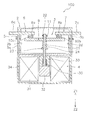
- the electromagnetic relay 100 includes a contact case 2, a contact device 3, a drive device 4, and a magnet portion 5.
- the contact case 2 has a substantially rectangular box shape and is made of an insulating material. In this embodiment, the contact case 2 is made of resin. The contact device 3 is housed in the contact case 2.
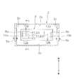
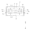
- FIG. 3 is a schematic view of the inside of the contact case 2 as viewed from above.
- the contact case 2 includes the first to fourth inner side surfaces 2a to 2d.
- Each of the first to fourth inner side surfaces 2a to 2d is an inner side surface of the contact case 2 located on the front, back, left and right sides.
- the first inner side surface 2a and the second inner side surface 2b are arranged so as to face each other in the front-rear direction.
- the first inner side surface 2a and the second inner side surface 2b extend in the vertical direction and the horizontal direction.
- the third inner side surface 2c and the fourth inner side surface 2d are arranged so as to face each other in the left-right direction.
- the third inner side surface 2c and the fourth inner side surface 2d extend in the vertical direction and the front-rear direction.
- the contact device 3 includes fixed terminals 6 and 7, fixed contacts 8a and 8b, a movable contact piece 9, movable contacts 10a and 10b, and a movable mechanism 11.
- the fixed terminals 6 and 7, the fixed contacts 8a and 8b, the movable contact piece 9 and the movable contacts 10a and 10b are made of a conductive material.
- the fixed contact 8a and the movable contact 10b in the present embodiment are examples of the first contact
- the fixed contact 8b and the movable contact 10a in the present embodiment are examples of the second contact.
- the fixed terminals 6 and 7 are plate-shaped terminals and extend in the left-right direction.
- the fixed terminals 6 and 7 are arranged so as to be spaced apart from each other in the left-right direction.
- the fixed terminal 6 includes an external connection portion 6a projecting to the left from the contact case 2.
- the fixed terminal 7 includes an external connection portion 7a projecting to the right from the contact case 2.
- the fixed contacts 8a and 8b are arranged in the contact case 2.
- the fixed contacts 8a and 8b have a substantially rectangular shape when viewed from the vertical direction.
- the fixed contacts 8a and 8b may have chamfered ends.
- the fixed contact 8a is arranged at the fixed terminal 6.
- the fixed contact 8a projects from the surface of the fixed terminal 6 facing the movable contact piece 9 toward the movable contact piece 9.
- the fixed contact 8a projects upward from the fixed terminal 6.
- the fixed contact 8b is arranged at the fixed terminal 7.
- the fixed contact 8b projects from the surface of the fixed terminal 7 facing the movable contact piece 9 toward the movable contact piece 9.
- the movable contact piece 9 is a plate-shaped member that is long in one direction and extends in the left-right direction in the contact case 2.
- the longitudinal direction of the movable contact piece 9 coincides with the left-right direction.
- the lateral direction of the movable contact piece 9 coincides with the front-rear direction.
- the movable contact piece 9 moves integrally with the movable contacts 10a and 10b.
- the movable contact piece 9 is arranged at a distance in the front-rear direction from the first inner side surface 2a and the second inner side surface 2b.
- Arc extension spaces 12a and 12b for extending an arc are provided between the movable contact piece 9 and the first inner side surface 2a, and between the movable contact piece 9 and the second inner side surface 2b.
- the movable contacts 10a and 10b are arranged on the movable contact piece 9.
- the movable contacts 10a and 10b have a substantially rectangular shape when viewed from the vertical direction.
- the ends of the movable contacts 10a and 10b may be chamfered.
- the movable contacts 10a and 10b can be moved to a closed position (position shown in FIG. 1) in contact with the fixed contacts 8a and 8b and an open position (position shown in FIG. 2) separated from the fixed contacts 8a and 8b.
- the movable contacts 10a and 10b can move in the contact direction Z1 that contacts the fixed contacts 8a and 8b and the opening direction Z2 that separates. In the present embodiment, the contact direction Z1 and the separation direction Z2 coincide with the vertical direction.
- the movable contact 10a is arranged at a position facing the fixed contact 8a, and protrudes from the movable contact piece 9 toward the fixed contact 8a.
- the movable contact 10b is arranged at a position facing the fixed contact 8b, and protrudes from the movable contact piece 9 toward the fixed contact 8b.
- the movable mechanism 11 moves the movable contact piece 9 between the closed position shown in FIG. 1 and the open position shown in FIG.
- the movable mechanism 11 moves the movable contacts 10a and 10b via the movable contact piece 9.
- the movable mechanism 11 includes a drive shaft 21, a first holding member 22, a second holding member 23, and a contact spring 24.
- the drive shaft 21 is connected to the movable contact piece 9.
- the drive shaft 21 extends in the vertical direction and penetrates the movable contact piece 9 in the vertical direction.
- the drive shaft 21 is provided so as to be movable in the contact direction Z1 and the separation direction Z2.
- the first holding member 22 is fixed to the drive shaft 21 above the movable contact piece 9.
- the second holding member 23 is fixed to the drive shaft 21 below the movable contact piece 9.
- the contact spring 24 is arranged between the movable contact piece 9 and the second holding member 23. The contact spring 24 urges the movable contact piece 9 in the contact direction Z1 via the second holding member 23.
- the drive device 4 moves the movable mechanism 11 in the contact direction Z1 and the opening direction Z2 by an electromagnetic force.
- the drive device 4 moves the movable contact piece 9 in the contact direction Z1 and the opening direction Z2 via the drive shaft 21.
- the drive device 4 includes a coil 31, a movable core 32, a fixed core 33, a yoke 34, and a return spring 35.
- the coil 31 When a voltage is applied and excited, the coil 31 generates an electromagnetic force that moves the movable iron core 32 in the contact direction Z1.
- the movable iron core 32 is integrally movably connected to the drive shaft 21.
- the fixed iron core 33 is arranged at a position facing the movable iron core 32.
- the yoke 34 is arranged so as to surround the coil 31.
- the return spring 35 is arranged between the movable iron core 32 and the fixed iron core 33. The return spring 35 urges the movable iron core 32 in the opening direction Z2.
- the magnet portion 5 generates a magnetic field that causes Lorentz forces F1 and F2 to act on an arc generated between the fixed contact 8a and the movable contact 10a and between the fixed contact 8b and the movable contact 10b.
- the magnet portion 5 has a first direction D1 in the arc generated between the fixed contact 8a and the movable contact 10a when the current flowing through the arc is directed from the movable contact 10a to the fixed contact 8a (from the back to the front of the paper surface in FIG. 3). It is arranged so that the Lorentz force F1 acts on the magnet. That is, the first direction D1 is the direction in which the arc generated between the fixed contact 8a and the movable contact 10a is extended.
- the direction of the Lorentz force F1 acting on the arc changes with the movement of the arc. Therefore, more accurately, the first direction D1 means the direction of the Lorentz force F1 acting on the arc at the time when the arc is generated between the fixed contact 8a and the movable contact 10a.
- the first direction D1 in this embodiment is forward.
- the first direction D1 is parallel to the lateral direction of the movable contact piece 9, and is a direction from the movable contact piece 9 toward the first inner side surface 2a.
- the magnet portion 5 includes a first magnet 5a and a second magnet 5b.
- the first magnet 5a and the second magnet 5b are permanent magnets.
- the first magnet 5a and the second magnet 5b have a substantially rectangular shape and extend in the front-rear direction and the up-down direction.
- the first magnet 5a is arranged on the outer periphery of the contact case 2 below the fixed terminal 6.
- the second magnet 5b is arranged on the outer periphery of the contact case 2 below the fixed terminal 7.
- the first magnet 5a is arranged so as to face the second magnet 5b in the left-right direction.
- the first magnet 5a and the second magnet 5b are arranged so that different poles face each other in the longitudinal direction of the movable contact piece 9.
- the N pole of the first magnet 5a is arranged so as to face the contact case 2.
- the second magnet 5b has an S pole facing the contact case 2.
- the magnetic flux flows in the direction from the first magnet 5a to the second magnet 5b by the first magnet 5a and the second magnet 5b arranged in this way. That is, magnetic flux flows around the fixed contacts 8a and 8b and the movable contacts 10a and 10b in a direction substantially parallel to the longitudinal direction of the movable contact piece 9. Therefore, for example, when a current flows from the movable contact 10a to the fixed contact 8a, the Lorentz force F1 acts on the arc generated between the fixed contact 8a and the movable contact 10a, and the arc moves to the arc extension space 12a. do.
- the Lorentz force F2 acts on the arc generated between the fixed contact 8b and the movable contact 10b in the second direction D2 in the direction opposite to the first direction D1. That is, the Lorentz force F2 acts on the arc generated between the fixed contact 8b and the movable contact 10b in the direction toward the second inner side surface 2b, and the arc moves to the arc extension space 12b.
- the direction in which the current flows will be described as the direction from the movable contact 10a to the fixed contact 8a. Therefore, on the movable contact 10b side, a current flows in the direction from the fixed contact 8b toward the movable contact 10b.
- the movable contacts 10a and 10b are in the open position as shown in FIG.
- the movable contacts 10a and 10b move from the open position to the closed position as shown in FIG.
- the movable iron core 32 moves in the contact direction Z1 against the elastic force of the return spring 35.
- the drive shaft 21 and the movable contact piece 9 move in the contact direction Z1 with the movement of the contact direction Z1 of the movable iron core 32, the movable contacts 10a and 10b move to the closed positions and come into contact with the fixed contacts 8a and 8b. ..
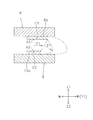
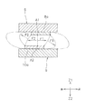
- FIG. 4 is a schematic cross-sectional view taken along the line LL of FIG. 3 around the movable contact 10a when the movable contact 10a is in the open position.
- FIG. 4 schematically shows how the arc generated between the fixed contact 8a and the movable contact 10a is extended.
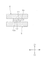
- FIG. 5 is a schematic cross-sectional view taken along the line LL of FIG. 3 around the movable contact 10a when the movable contact 10a is in the closed position.
- the fixed contact 8a protrudes in the first direction D1 (here, forward) from the movable contact 10a.
- the movable contact 10a is shorter than the fixed contact 8a in the first direction D1.
- the fixed contact 8a is displaced in the first direction D1 with respect to the movable contact 10a. That is, the fixed contact 8a is deviated from the movable contact 10a in the direction in which the arc is extended (the same direction as the Lorentz force F1).
- the center position C1 of the fixed contact 8a and the center position C2 of the movable contact 10a are in the first direction. They are offset from each other by D1.
- the center position C1 of the fixed contact 8a is located at the center of the fixed contact 8a in the front-rear direction.
- the center position C2 of the movable contact 10a is located at the center of the movable contact 10a in the front-rear direction.
- the center position C1 of the fixed contact 8a and the center position C2 of the movable contact 10a are deviated from each other in the first direction D1 when viewed from the moving direction of the movable contact 10a. That is, the center position C1 of the fixed contact 8a does not overlap with the center position C2 of the movable contact 10a in the vertical direction. In the present embodiment, the center position C1 of the fixed contact 8a is deviated from the center position C2 of the movable contact 10a in the first direction D1.
- the first end portion A1 of the arc and the second end portion A2 of the arc are displaced in the vertical direction, so that the direction of the Lorentz force F1 acting on the arc changes in the forward direction and the opening direction Z2. That is, the Lorentz force F1 acts in a direction in which the second end portion A2 of the arc is easily moved from the movable contact 10a to the movable contact piece 9. As a result, the second end portion A2 of the arc can be quickly moved to the movable contact piece 9. As a result, the arc can be quickly moved in the first direction D1.
- the arc generated between the fixed contact 8a and the movable contact 10a has a characteristic that it easily sticks at the end of the fixed contact 8a and the end of the movable contact 10a. Further, the arc has a characteristic that the cathode side contact is easier to move than the anode side contact.
- the anode-side contact and the cathode-side contact are determined by the direction in which the current flows. Specifically, in the fixed contact 8a and the movable contact 10a, the contact located on the upstream side in the direction in which the current flows is the anode side contact, and the contact located on the downstream side is the cathode side contact.
- the movable contact 10a becomes the anode side contact and the fixed contact 8a becomes the cathode side contact.
- the Lorentz force F1 acts in the direction in which the second end A2 of the arc on the movable contact 10a side, which is easier to move than the first end A1 of the arc on the fixed contact 8a side, moves to the movable contact piece 9. ..
- the end portion of the arc can be moved to the movable contact piece 9 more effectively, so that the arc can be moved more quickly.
- the present invention is not limited to the above embodiment, and various changes can be made without departing from the gist of the invention.
- the shapes or arrangements of the contact case 2, the contact device 3, and the drive device 4 may be changed.
- the present invention has been described by exemplifying a plunger type electromagnetic relay, but the present invention may be applied to, for example, a hinge type electromagnetic relay.
- a hinge type electromagnetic relay In the case of a hinge type electromagnetic relay, the configuration corresponding to the fixed terminal 7, the fixed contact 8b and the movable contact 10b may be omitted.
- the present invention may be applied to an electromagnetic relay that operates so that the movable contact piece 9 is pulled toward the fixed terminals 6 and 7.
- the fixed contact 8a protrudes from the movable contact 10a in the first direction D1
- the movable contact 10a may protrude from the fixed contact 8a in the first direction D1.
- the shape of the fixed contact 8a in the embodiment may be the shape of the movable contact 10a
- the shape of the movable contact 10a in the embodiment may be the shape of the fixed contact 8a.
- the movable contact 10a is an example of the first contact and the fixed contact 8a is an example of the second contact, and the first end portion A1 of the arc can be quickly moved to the fixed terminal 6 by the Lorentz force F1.
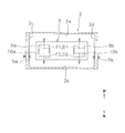
- FIG. 6 is a schematic view of the inside of the contact case 2 according to another embodiment as viewed from above.
- FIG. 7 is a schematic cross-sectional view taken along the line L1-L1 of FIG. 6 around the movable contact 10a when the movable contact 10a is in the open position.
- the movable contact 10a may protrude in the second direction D2 from the fixed contact 8a.
- the fixed contact 8a protrudes from the movable contact 10a in the first direction D1.
- the magnet portion 5 has a second direction D2 in the arc generated between the fixed contact 8a and the movable contact 10a when the current flowing through the arc is directed from the fixed contact 8a to the movable contact 10a (from the front to the back of the paper in FIG. 6).
- the Lorentz force F2 is arranged so as to act on the magnet.
- the configuration of the magnet portion 5 is the same as that of the above embodiment. In this case, when the current flowing through the arc goes from the fixed contact 8a to the movable contact 10a, the Lorentz force F2 is generated in the direction in which the first end A1 of the arc of the fixed contact 8a, which is the anode side contact, moves to the fixed terminal 6. It works.
- the end of the arc can be quickly moved to the fixed terminal 6 or the movable contact piece 9 in which the fixed contact 8a or the movable contact 10a, which is the contact on the anode side, is arranged. ..
- the configuration of the magnet portion 5 is not limited to the above embodiment.
- the first magnet 5a and the second magnet 5b may be arranged so that the N poles face each other in the longitudinal direction of the movable contact piece 9. That is, a magnetic flux flows around the fixed contact 8a and the movable contact 10a in the direction from the first magnet 5a toward the second magnet 5b, and around the fixed contact 8b and the movable contact 10b in the direction from the second magnet 5b toward the first magnet 5a.
- the magnet portion 5 may be configured so that the magnetic flux flows.
- the fixed contact 8a and the movable contact 10a have the same configuration as shown in FIG.
- the fixed contact 8b and the movable contact 10b have the same configuration as the fixed contact 8a and the movable contact 10b. In this case, even if the energization direction changes, the anode-side contact is always shorter than the cathode-side contact on the movable contact 10a side and the movable contact 10b side in the direction in which the arc is extended, so that the end of the arc The part can be moved quickly.
- the first magnet 5a and the second magnet 5b may be arranged so that the S poles face each other in the longitudinal direction of the movable contact piece 9. That is, a magnetic flux flows around the fixed contact 8a and the movable contact 10a in the direction from the second magnet 5b toward the first magnet 5a, and around the fixed contact 8b and the movable contact 10b in the direction from the first magnet 5a toward the second magnet 5b.
- the magnet portion 5 may be configured so that the magnetic flux flows.
- the fixed contacts 8a and 8b and the movable contacts 10a and 10b have the same configuration as the fixed contacts 8b and the movable contacts 10b shown in FIG.
- the magnet portion 5 may be configured so that the magnetic flux flows in a direction substantially parallel to the lateral direction of the movable contact piece 9.
- the first magnet 5a and the second magnet 5b may be arranged so as to face each other in the lateral direction of the movable contact piece 9.
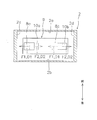
- the relay has polarity or the configuration in which the magnetic flux flows in the direction from the second inner side surface 2b to the first inner side surface 2a, as shown in FIG. 10, it is movable with the fixed contacts 8a and 8b.
- the contacts 10a and 10b may be arranged so as to be displaced in the direction in which the arc is extended (here, the left-right direction).
- the direction in which the Lorentz forces F1 and F2 act is parallel to the longitudinal direction of the movable contact piece 9.
- the Lorentz force F1 acts in the direction toward the third inner side surface 2c with respect to the arc generated between the fixed contact 8a and the movable contact 10a.
- the Lorentz force F2 acts in the direction toward the fourth inner side surface 2d with respect to the arc generated between the fixed contact 8b and the movable contact 10b. do.
- the anode-side contact is always shorter than the cathode-side contact in the direction in which the arc is extended, the end of the arc can be moved quickly.
- the arc can be moved quickly in an electromagnetic relay.
Landscapes
- Physics & Mathematics (AREA)
- Electromagnetism (AREA)
- Arc-Extinguishing Devices That Are Switches (AREA)
Abstract
電磁継電器は、固定端子と、可動接触片と、第1接点と、第2接点と、可動機構と、磁石部とを備える。第1接点は、固定端子及び可動接触片のいずれか一方に配置される。第2接点は、第1接点と接触可能であり、固定端子及び可動接触片のいずれか他方に配置される。可動機構は、第1接点と第2接点とが接触する閉位置と、第1接点と第2接点とが開離した開位置とに可動接触片を移動させる。磁石部は、第1接点と第2接点との間で生じるアークにローレンツ力を作用させる磁界を発生させる。磁石部は、アークに流れる電流が第2接点から第1接点に向かうときに第1方向にローレンツ力が作用するように配置される。第1接点及び第2接点のいずれか一方は、第1接点及び第2接点のいずれか他方よりも第1方向に突出する。
Description
本発明は、電磁継電器に関する。
従来、電気回路を開閉する電磁継電器が知られている。例えば、特許文献1の電磁継電器は、固定端子と、固定端子に配置された固定接点と、可動接触片と、可動接触片に配置された可動接点と、を備えている。可動接点は、固定接点に接触可能であり、可動接点が固定接点に接触又は固定接点から開離することで、電気回路が開閉される。また、電磁継電器には、可動接点が固定接点から開離するときに発生するアークを伸長させるための永久磁石が設けられている。
特許文献1の電磁継電器では、アークが発生したときに、固定接点及び可動接点の端部、或いは接点と端子との境界部分にアークが膠着して、アークの移動が阻害されるおそれがある。
本発明の課題は、電磁継電器において、アークを迅速に移動させることにある。
本発明の一態様に係る電磁継電器は、固定端子と、可動接触片と、第1接点と、第2接点と、可動機構と、磁石部とを備える。第1接点は、固定端子及び可動接触片のいずれか一方に配置される。第2接点は、第1接点と接触可能であり、固定端子及び可動接触片のいずれか他方に配置される。可動機構は、第1接点と第2接点とが接触する閉位置と、第1接点と第2接点とが開離した開位置とに可動接触片を移動させる。磁石部は、第1接点と第2接点との間で生じるアークにローレンツ力を作用させる磁界を発生させる。磁石部は、アークに流れる電流が第2接点から第1接点に向かうときに第1方向にローレンツ力が作用するように配置される。第1接点及び第2接点のいずれか一方は、第1接点及び第2接点のいずれか他方よりも第1方向に突出する。第1接点と第2接点とが接触した状態において、第1接点の中心位置と第2接点の中心位置とは、第1方向に互いにずれている。
この電磁継電器では、例えば、第1接点が第2接点よりも第1方向に突出している場合、第1方向に位置する第1接点の端部までの距離が、第2接点の第1方向に位置する第2接点の端部までの距離よりも大きくなる。このため、第1接点側のアークの端部は、第2接点側のアークの端部よりも第1方向に移動する。これにより、アークに作用するローレンツ力の方向が変化して、第2接点が配置される端子(固定端子及び可動接触片のいずれか一方)に第2接点側のアークの端部が端子に移動し易くなる。すなわち、アークに作用するローレンツ力の方向が変化することで、第2接点が配置される端子に第2接点側のアークの端部を迅速に移動させることができる。その結果、第1方向にアークを迅速に移動させることができる。
第1接点は、第2接点よりも第1方向に突出してもよい。この場合、アークに流れる電流が第2接点から第1接点に向かうときに、陰極側接点となる第1接点よりもアークの端部が移動し易い陽極側接点となる第2接点側のアークの端部が端子に移動する方向にローレンツ力が作用する。これにより、より効果的にアークの端部の一方を端子に移動させることができるので、さらにアークを迅速に移動させることができる。
第2接点は、第1接点よりも第1方向と反対の第2方向に突出してもよい。磁石部は、アークに流れる電流が第1接点から第2接点に向かうときに第2方向にローレンツ力が作用するように配置されてもよい。この場合は、いずれの通電方向であっても、陽極側接点となる第1接点及び第2接点のいずれか一方の接点が配置される端子にアークの端部を迅速に移動させることができる。
第1接点と第2接点とが開離した状態において、第1接点の中心位置と第2接点の中心位置とは、第1方向に互いにずれていてもよい。この場合においても、第1方向にアークを迅速に移動させることができる。
本発明によれば、電磁継電器において、アークを迅速に移動させることができる。
以下、本発明の一態様に係る電磁継電器の実施形態について、図面を参照して説明する。 なお、図面を参照するときにおいて、説明を分かり易くするために図1における上側を「上」、下側を「下」、左側を「左」、右側を「右」として説明する。また、図1の紙面と直交する方向を前後方向として説明する。これらの方向は、説明の便宜上、定義されるものであって、電磁継電器100の配置方向を限定するものではない。
図1及び図2は電磁継電器100の断面模式図である。電磁継電器100は、接点ケース2、接点装置3と、駆動装置4と、磁石部5とを備えている。
接点ケース2は、略四角形の箱型であり、絶縁性を有する材料で形成されている。本実施形態では、接点ケース2は樹脂製である。接点ケース2内には、接点装置3が収容されている。
図3は、接点ケース2の内部を上方から見た模式図である。接点ケース2は、第1~第4内側面2a~2dを含む。第1~第4内側面2a~2dのそれぞれは、前後左右に位置する接点ケース2の内側面である。第1内側面2a及び第2内側面2bは、前後方向に互いに対向して配置されている。第1内側面2a及び第2内側面2bは、上下方向及び左右方向に延びている。第3内側面2c及び第4内側面2dは、左右方向に互いに対向して配置されている。第3内側面2c及び第4内側面2dは、上下方向かつ前後方向に延びている。
接点装置3は、固定端子6,7と、固定接点8a,8bと、可動接触片9と、可動接点10a,10bと、可動機構11とを含む。固定端子6,7、固定接点8a,8b、可動接触片9及び可動接点10a,10bは、導電性を有する材料で形成されている。本実施形態における固定接点8a及び可動接点10bは、第1接点の一例であり、本実施形態における固定接点8b及び可動接点10aは第2接点の一例である。
固定端子6,7は、板状の端子であり、左右方向に延びている。固定端子6,7は、左右方向に互いに間隔を隔てて配置されている。固定端子6は、接点ケース2から左方に突出する外部接続部6aを含む。固定端子7は、接点ケース2から右方に突出する外部接続部7aを含む。
固定接点8a,8bは、接点ケース2内に配置されている。固定接点8a,8bは、上下方向から見て、略矩形状である。固定接点8a,8bは、端部が面取りされていてもよい。固定接点8aは、固定端子6に配置されている。固定接点8aは、固定端子6の可動接触片9に対向する面から可動接触片9に向かって突出している。ここでは、固定接点8aは、固定端子6から上方に突出している。固定接点8bは、固定端子7に配置されている。固定接点8bは、固定端子7の可動接触片9に対向する面から可動接触片9に向かって突出している。
可動接触片9は、一方向に長い板状部材であり、接点ケース2内で左右方向に延びている。本実施形態では、可動接触片9の長手方向は、左右方向と一致する。また、可動接触片9の短手方向は、前後方向と一致する。可動接触片9は、可動接点10a,10bと一体的に移動する。可動接触片9は、第1内側面2a及び第2内側面2bと前後方向に間隔を隔てて配置されている。可動接触片9と第1内側面2aとの間、及び可動接触片9と第2内側面2bとの間には、アークを伸長させるためのアーク伸長空間12a,12bが設けられている。
可動接点10a,10bは、可動接触片9に配置されている。可動接点10a,10bは、上下方向から見て、略矩形状である。可動接点10a,10bは、端部が面取りされていてもよい。可動接点10a,10bは、固定接点8a,8bに接触する閉位置(図1に示す位置)と固定接点8a,8bから開離した開位置(図2に示す位置)とに移動可能である。可動接点10a,10bは、固定接点8a,8bに接触する接触方向Z1と開離する開離方向Z2とに移動可能である。本実施形態では、接触方向Z1及び開離方向Z2は、上下方向と一致する。
可動接点10aは、固定接点8aと対向する位置に配置され、可動接触片9から固定接点8aに向かって突出している。可動接点10bは、固定接点8bと対向する位置に配置され、可動接触片9から固定接点8bに向かって突出している。
可動機構11は、図1に示す閉位置と、図2に示す開位置とに可動接触片9を移動させる。可動機構11は、可動接触片9を介して可動接点10a,10bを移動させる。可動機構11は、駆動軸21と、第1保持部材22と、第2保持部材23と、接点バネ24とを含む。駆動軸21は、可動接触片9に連結される。駆動軸21は、上下方向に延びており、可動接触片9を上下方向に貫通している。駆動軸21は、接触方向Z1及び開離方向Z2に移動可能に設けられる。
第1保持部材22は、可動接触片9よりも上方で駆動軸21に固定されている。第2保持部材23は、可動接触片9よりも下方で駆動軸21に固定されている。接点バネ24は、可動接触片9と第2保持部材23の間に配置されている。接点バネ24は、第2保持部材23を介して可動接触片9を接触方向Z1に付勢する。
駆動装置4は、電磁力によって可動機構11を接触方向Z1及び開離方向Z2に移動させる。本実施形態では、駆動装置4は、駆動軸21を介して可動接触片9を接触方向Z1及び開離方向Z2に移動させる。駆動装置4は、コイル31と、可動鉄心32と、固定鉄心33と、ヨーク34と、復帰バネ35と、を含む。
コイル31は、電圧が印加されて励磁されると、可動鉄心32を接触方向Z1に移動させる電磁力を発生させる。可動鉄心32は、駆動軸21に一体移動可能に連結されている。固定鉄心33は、可動鉄心32と対向する位置に配置されている。ヨーク34は、コイル31を囲むように配置されている。復帰バネ35は、可動鉄心32と固定鉄心33の間に配置されている。復帰バネ35は、可動鉄心32を開離方向Z2に付勢する。
磁石部5は、固定接点8aと可動接点10aとの間、及び固定接点8bと可動接点10bとの間で生じるアークにローレンツ力F1,F2を作用させる磁界を発生させる。磁石部5は、アークに流れる電流が可動接点10aから固定接点8a(図3の紙面の奥から手前)に向かうときに、固定接点8aと可動接点10aとの間で生じるアークに第1方向D1にローレンツ力F1が作用するように配置されている。すなわち、第1方向D1は、固定接点8aと可動接点10aとの間で生じるアークが伸長される方向である。ただし、本実施形態では、アークに作用するローレンツ力F1の方向がアークの移動に伴い変化する。このため、より正確には、第1方向D1は、固定接点8aと可動接点10aとの間でアークが発生した時点のアークに作用するローレンツ力F1の方向を意味する。本実施形態における第1方向D1は、前方である。第1方向D1は、可動接触片9の短手方向に平行であり、可動接触片9から第1内側面2aに向かう方向である。
磁石部5は、第1磁石5aと、第2磁石5bとを含む。第1磁石5a及び第2磁石5bは、永久磁石である。第1磁石5a及び第2磁石5bは、略矩形状であり、前後方向かつ上下方向に延びている。第1磁石5aは、固定端子6の下方で接点ケース2の外周に配置されている。第2磁石5bは、固定端子7の下方で接点ケース2の外周に配置されている。第1磁石5aは、第2磁石5bと左右方向に対向して配置されている。第1磁石5aと第2磁石5bとは、可動接触片9の長手方向に異極が互いに対向するように配置されている。第1磁石5aは、N極が接点ケース2に面して配置されている。第2磁石5bは、S極が接点ケース2に面して配置されている。
このように配置された第1磁石5aと第2磁石5bとによって、第1磁石5aから第2磁石5bに向かう方向に磁束が流れる。すなわち、固定接点8a,8b及び可動接点10a,10bの周辺には、可動接触片9の長手方向と略平行な方向に磁束が流れる。したがって、例えば、可動接点10aから固定接点8aに向けて電流が流れる場合は、固定接点8aと可動接点10aとの間で生じるアークにローレンツ力F1が作用して、アークがアーク伸長空間12aに移動する。一方、固定接点8bと可動接点10bとの間で生じるアークには、第1方向D1と反対方向の第2方向D2にローレンツ力F2が作用する。すなわち、固定接点8bと可動接点10bとの間で生じるアークには、第2内側面2bに向かう方向にローレンツ力F2が作用して、アークがアーク伸長空間12bに移動する。なお、本実施形態では、特に断りがない限り、電流が流れる方向を可動接点10aから固定接点8aに向かう方向として説明する。したがって、可動接点10b側では、固定接点8bから可動接点10bに向かう方向に電流が流れる。
次に、電磁継電器100の動作について説明する。駆動装置4が励磁されていない状態では、図1に示すように、可動接点10a,10bが開位置にある。駆動装置4が励磁されると、図2に示すように、可動接点10a,10bが開位置から閉位置に移動する。詳細には、コイル31に電圧が印加されると、可動鉄心32が復帰バネ35の弾性力に抗して接触方向Z1に移動する。可動鉄心32の接触方向Z1の移動に伴い、駆動軸21及び可動接触片9が接触方向Z1に移動することで、可動接点10a,10bが閉位置に移動して固定接点8a,8bに接触する。一方、コイル31への電圧の印加が停止されると、可動鉄心32が復帰バネ35の弾性力によって可動接触片9とともに開離方向Z2に移動することで、可動接点10a,10bが閉位置に移動する。
次に、固定接点8aと可動接点10aの詳細について説明する。図4は、可動接点10aが開位置にあるときの可動接点10a周辺を図3のL-L線で切断した断面模式図である。図4では、固定接点8aと可動接点10aとの間で生じたアークが伸長されていく様子を模式的に示している。図5は、可動接点10aが閉位置にあるときの可動接点10a周辺を図3のL-L線で切断した断面模式図である。
固定接点8aは、可動接点10aよりも第1方向D1(ここでは前方)に突出している。可動接点10aは、第1方向D1において、固定接点8aよりも短い。固定接点8aは、可動接点10aに対して第1方向D1にずれている。すなわち、固定接点8aは、可動接点10aに対してアークが伸長される方向(ローレンツ力F1と同じ方向)にずれている。
図4及び図5に示すように、固定接点8aと可動接点10aとが接触した状態及び開離した状態において、固定接点8aの中心位置C1と可動接点10aの中心位置C2とは、第1方向D1に互いにずれている。固定接点8aの中心位置C1は、前後方向における固定接点8aの中心に位置している。可動接点10aの中心位置C2は、前後方向における可動接点10aの中心に位置している。図3に示すように、可動接点10aの移動方向からみて、固定接点8aの中心位置C1と可動接点10aの中心位置C2とは、第1方向D1に互いにずれている。すなわち、固定接点8aの中心位置C1は、可動接点10aの中心位置C2と上下方向に重ならない。本実施形態では、固定接点8aの中心位置C1は、可動接点10aの中心位置C2に対して第1方向D1にずれている。
図4に示すように、固定接点8aと可動接点10aの間で生じたアークにローレンツ力F1が作用すると、固定接点8a側のアークの第1端部A1と、可動接点10a側のアークの第2端部A2とが第1内側面2aに近づく方向に移動する。このとき、固定接点8aが可動接点10aに対してアークが伸長される第1方向D1にずれているので、アークの第1端部A1は、アークの第2端部A2よりも第1内側面2aに近づく方向に移動する。これにより、アークの第1端部A1とアークの第2端部A2とが上下方向にずれるので、アークに作用するローレンツ力F1の方向が前方かつ開離方向Z2に向かう方向に変化する。すなわち、アークの第2端部A2が可動接点10aから可動接触片9に移動し易くなる方向にローレンツ力F1が作用する。これにより、可動接触片9にアークの第2端部A2を迅速に移動させることができる。その結果、第1方向D1にアークを迅速に移動させることができる。
ここで、固定接点8aと可動接点10aの間で生じたアークは、固定接点8aの端部及び可動接点10aの端部において膠着し易いといった特性がある。また、アークは、陽極側接点よりも陰極側接点の方が移動し易いといった特性がある。陽極側接点及び陰極側接点は、電流が流れる方向によって定まる。具体的には、固定接点8aと可動接点10aとにおいて、電流が流れる方向の上流側に位置する接点が陽極側接点であり、下流側に位置する接点が陰極側接点である。したがって、可動接点10aから固定接点8aに向かう方向に電流が流れる場合は、可動接点10aが陽極側接点、固定接点8aが陰極側接点となる。本実施形態では、固定接点8a側のアークの第1端部A1よりも移動し易い可動接点10a側のアークの第2端部A2が可動接触片9に移動する方向にローレンツ力F1が作用する。これにより、より効果的にアークの端部を可動接触片9に移動させることができるので、さらにアークを迅速に移動させることができる。
なお、可動接点10b側では、図3に示すように、陰極側接点である可動接点10bを陽極側接点である固定接点8bに対して第2方向D2にずらすことが好ましい。これにより、可動接点10a側と同様の効果を得ることができる。
以上、本発明の一態様に係る電磁継電器の実施形態について説明したが、本発明は上記実施形態に限定されるものではなく、発明の要旨を逸脱しない範囲で種々の変更が可能である。例えば、接点ケース2、接点装置3及び駆動装置4の形状、或いは配置が変更されてもよい。前記実施形態では、プランジャ型の電磁継電器を例示して本発明を説明したが、例えば、ヒンジ型の電磁継電器に本発明を適用してもよい。ヒンジ型の電磁継電器の場合、固定端子7、固定接点8b及び可動接点10bに対応する構成は、省略されてもよい。また、可動接触片9が固定端子6,7に向けて引き込まれるように動作する電磁継電器に本発明を適用してもよい。
前記実施形態では、固定接点8aが可動接点10aよりも第1方向D1に突出していたが、可動接点10aが固定接点8aよりも第1方向D1に突出する構成であってもよい。すなわち、前記実施形態における固定接点8aの形状を可動接点10aの形状にして、前記実施形態における可動接点10aの形状を固定接点8aの形状にしてもよい。この場合は、可動接点10aが第1接点の一例、固定接点8aが第2接点の一例となり、アークの第1端部A1をローレンツ力F1によって固定端子6に迅速に移動させることができる。
図6は、他の実施形態に係る接点ケース2の内部を上方から見た模式図である。図7は、可動接点10aが開位置にあるときの可動接点10a周辺を図6のL1-L1線で切断した断面模式図である。図6及び図7に示すように、可動接点10aは、固定接点8aよりも第2方向D2に突出してもよい。なお、前記実施形態と同様に、固定接点8aは、可動接点10aよりも第1方向D1に突出している。磁石部5は、アークに流れる電流が固定接点8aから可動接点10a(図6の紙面の手前から奥)に向かうときに、固定接点8aと可動接点10aとの間で生じるアークに第2方向D2にローレンツ力F2が作用するように配置されている。磁石部5の構成は、前記実施形態と同様である。この場合は、アークに流れる電流が固定接点8aから可動接点10aに向かうときに、陽極側接点となる固定接点8aのアークの第1端部A1が固定端子6に移動する方向にローレンツ力F2が作用する。すなわち、通電方向が変化した場合であっても、陽極側接点となる固定接点8a又は可動接点10aが配置される固定端子6又は可動接触片9にアークの端部を迅速に移動させることができる。
なお、可動接点10b側については、固定接点8bを可動接点10bに対して第1方向D1にずらすことが好ましい。これにより、可動接点10b側についても、可動接点10a側と同様の効果を得ることができる。
磁石部5の構成は、前記実施形態に限定されるものではない。例えば、図8に示すように、第1磁石5aと第2磁石5bは、可動接触片9の長手方向にN極が互いに対向するように配置されてもよい。すなわち、固定接点8a及び可動接点10a周辺に第1磁石5aから第2磁石5bに向かう方向に磁束が流れ、固定接点8b及び可動接点10b周辺に第2磁石5bから第1磁石5aに向かう方向に磁束が流れるように磁石部5が構成されてもよい。固定接点8a及び可動接点10aは、図6に示す構成と同じである。固定接点8b及び可動接点10bは、固定接点8a及び可動接点10bと同様の構成である。この場合は、通電方向が変化した場合であっても、可動接点10a側及び可動接点10b側において、常に陽極側接点が陰極側接点よりもアークが伸長される方向に短くなるので、アークの端部を迅速に移動させることができる。
図9に示すように、第1磁石5aと第2磁石5bは、可動接触片9の長手方向にS極が互いに対向するように配置されてもよい。すなわち、固定接点8a及び可動接点10a周辺に第2磁石5bから第1磁石5aに向かう方向に磁束が流れ、固定接点8b及び可動接点10b周辺に第1磁石5aから第2磁石5bに向かう方向に磁束が流れるように磁石部5が構成されてもよい。固定接点8a,8b及び可動接点10a,10bは、図6に示す固定接点8b及び可動接点10bと同様の構成である。
図10に示すように、可動接触片9の短手方向と略平行な方向に磁束が流れるように磁石部5が構成されてもよい。例えば、第1磁石5aと第2磁石5bとが可動接触片9の短手方向に対向して配置されてもよい。また、リレーが極性を有する構造の場合や、第2内側面2bから第1内側面2aに向かう方向に磁束が流れる構成の場合は、図10に示すうように、固定接点8a,8bと可動接点10a,10bをアークが伸長される方向(ここでは、左右方向)にずらして配置してもよい。この場合は、ローレンツ力F1,F2が作用する方向が可動接触片9の長手方向と平行になる。可動接点10aから固定接点8aに向かう方向に電流が流れる場合は、固定接点8aと可動接点10aとの間で生じるアークに対して、ローレンツ力F1が第3内側面2cに向かう方向に作用する。一方、固定接点8aから可動接点10aに向かう方向に電流が流れる場合は、固定接点8bと可動接点10bとの間で生じるアークに対して、ローレンツ力F2が第4内側面2dに向かう方向に作用する。この場合でも、常に陽極側接点が陰極側接点よりもアークが伸長される方向に短くなるので、アークの端部を迅速に移動させることができる。
本発明によれば、電磁継電器において、アークを迅速に移動させることができる。
5 磁石部
6 固定端子
7 可動接触片
8a 固定接点
10a 可動接点
11 可動機構
100 電磁継電器
D1 第1方向
D2 第2方向
6 固定端子
7 可動接触片
8a 固定接点
10a 可動接点
11 可動機構
100 電磁継電器
D1 第1方向
D2 第2方向
Claims (4)
- 固定端子と、
可動接触片と、
前記固定端子及び前記可動接触片のいずれか一方に配置される第1接点と、
前記第1接点と接触可能であり、前記固定端子及び前記可動接触片のいずれか他方に配置される第2接点と、
前記第1接点と前記第2接点とが接触する閉位置と、前記第1接点と前記第2接点とが開離した開位置とに前記可動接触片を移動させる可動機構と、
前記第1接点と前記第2接点との間で生じるアークにローレンツ力を作用させる磁界を発生させる磁石部と、
を備え、
前記磁石部は、前記アークに流れる電流が前記第2接点から前記第1接点に向かうときに第1方向に前記ローレンツ力が作用するように配置され、
前記第1接点及び前記第2接点のいずれか一方は、前記第1接点及び前記第2接点のいずれか他方よりも前記第1方向に突出し、
前記第1接点と前記第2接点とが接触した状態において、前記第1接点の中心位置と前記第2接点の中心位置とは、前記第1方向に互いにずれている、
電磁継電器。 - 前記第1接点は、前記第2接点よりも前記第1方向に突出する、
請求項1に記載の電磁継電器。 - 前記第2接点は、前記第1接点よりも前記第1方向と反対の第2方向に突出し、
前記磁石部は、前記アークに流れる電流が前記第1接点から前記第2接点に向かうときに前記第2方向に前記ローレンツ力が作用するように配置されている、
請求項2に記載の電磁継電器。 - 前記第1接点と前記第2接点とが開離した状態において、前記第1接点の中心位置と前記第2接点の中心位置とは、前記第1方向に互いにずれている、
請求項1から3のいずれか1項に記載の電磁継電器。
Priority Applications (3)
| Application Number | Priority Date | Filing Date | Title |
|---|---|---|---|
| CN202180043948.3A CN115836375B (zh) | 2020-07-02 | 2021-06-16 | 电磁继电器 |
| US18/011,191 US12183529B2 (en) | 2020-07-02 | 2021-06-16 | Electromagnetic relay |
| DE112021003578.9T DE112021003578T5 (de) | 2020-07-02 | 2021-06-16 | Elektromagnetisches Relais |
Applications Claiming Priority (2)
| Application Number | Priority Date | Filing Date | Title |
|---|---|---|---|
| JP2020-114971 | 2020-07-02 | ||
| JP2020114971A JP7380455B2 (ja) | 2020-07-02 | 2020-07-02 | 電磁継電器 |
Publications (1)
| Publication Number | Publication Date |
|---|---|
| WO2022004378A1 true WO2022004378A1 (ja) | 2022-01-06 |
Family
ID=79316125
Family Applications (1)
| Application Number | Title | Priority Date | Filing Date |
|---|---|---|---|
| PCT/JP2021/022803 Ceased WO2022004378A1 (ja) | 2020-07-02 | 2021-06-16 | 電磁継電器 |
Country Status (5)
| Country | Link |
|---|---|
| US (1) | US12183529B2 (ja) |
| JP (1) | JP7380455B2 (ja) |
| CN (1) | CN115836375B (ja) |
| DE (1) | DE112021003578T5 (ja) |
| WO (1) | WO2022004378A1 (ja) |
Families Citing this family (3)
| Publication number | Priority date | Publication date | Assignee | Title |
|---|---|---|---|---|
| JP7067580B2 (ja) * | 2020-03-18 | 2022-05-16 | 株式会社デンソーエレクトロニクス | 電磁継電器、および、電磁継電器の製造方法 |
| JP7593276B2 (ja) * | 2021-09-17 | 2024-12-03 | オムロン株式会社 | 電磁継電器 |
| JP7513644B2 (ja) | 2022-01-31 | 2024-07-09 | プライムプラネットエナジー&ソリューションズ株式会社 | 電池パック |
Citations (3)
| Publication number | Priority date | Publication date | Assignee | Title |
|---|---|---|---|---|
| JP2016031803A (ja) * | 2014-07-28 | 2016-03-07 | 富士通コンポーネント株式会社 | 電磁継電器 |
| JP2017010719A (ja) * | 2015-06-19 | 2017-01-12 | 富士通コンポーネント株式会社 | 電磁継電器 |
| JP2020035561A (ja) * | 2018-08-28 | 2020-03-05 | オムロン株式会社 | 電磁継電器 |
Family Cites Families (14)
| Publication number | Priority date | Publication date | Assignee | Title |
|---|---|---|---|---|
| JP3321963B2 (ja) * | 1994-02-22 | 2002-09-09 | 株式会社デンソー | プランジャ型電磁継電器 |
| US7859372B2 (en) * | 2007-10-24 | 2010-12-28 | Tyco Electronics Corporation | Methods and apparatus for reducing bounce between relay contacts |
| JP5829616B2 (ja) * | 2010-11-01 | 2015-12-09 | 日本特殊陶業株式会社 | 継電器 |
| JP5623873B2 (ja) * | 2010-11-08 | 2014-11-12 | パナソニック株式会社 | 電磁リレー |
| JP5675337B2 (ja) | 2010-12-28 | 2015-02-25 | 富士通コンポーネント株式会社 | 電磁継電器 |
| JP5585550B2 (ja) * | 2011-07-18 | 2014-09-10 | アンデン株式会社 | 継電器 |
| JP2017195160A (ja) * | 2016-04-22 | 2017-10-26 | オムロン株式会社 | 電磁継電器 |
| JP2017195161A (ja) * | 2016-04-22 | 2017-10-26 | オムロン株式会社 | 接点機構および電磁継電器 |
| JP2019032944A (ja) * | 2017-08-04 | 2019-02-28 | オムロン株式会社 | 電磁継電器およびスマートメータ |
| JP6907801B2 (ja) * | 2017-08-10 | 2021-07-21 | オムロン株式会社 | 電磁継電器 |
| JP6996412B2 (ja) * | 2018-04-26 | 2022-01-17 | 株式会社Soken | 電磁継電器 |
| JP7077890B2 (ja) * | 2018-09-14 | 2022-05-31 | 富士電機機器制御株式会社 | 接点機構及びこれを使用した電磁接触器 |
| CN109243924A (zh) * | 2018-09-29 | 2019-01-18 | 厦门赛特勒继电器有限公司 | 小尺寸高压直流继电器及消灭电磁继电器电弧的方法 |
| JP7142220B2 (ja) * | 2018-11-13 | 2022-09-27 | パナソニックIpマネジメント株式会社 | 接点装置及び電磁継電器 |
-
2020
- 2020-07-02 JP JP2020114971A patent/JP7380455B2/ja active Active
-
2021
- 2021-06-16 DE DE112021003578.9T patent/DE112021003578T5/de active Pending
- 2021-06-16 CN CN202180043948.3A patent/CN115836375B/zh active Active
- 2021-06-16 US US18/011,191 patent/US12183529B2/en active Active
- 2021-06-16 WO PCT/JP2021/022803 patent/WO2022004378A1/ja not_active Ceased
Patent Citations (3)
| Publication number | Priority date | Publication date | Assignee | Title |
|---|---|---|---|---|
| JP2016031803A (ja) * | 2014-07-28 | 2016-03-07 | 富士通コンポーネント株式会社 | 電磁継電器 |
| JP2017010719A (ja) * | 2015-06-19 | 2017-01-12 | 富士通コンポーネント株式会社 | 電磁継電器 |
| JP2020035561A (ja) * | 2018-08-28 | 2020-03-05 | オムロン株式会社 | 電磁継電器 |
Also Published As
| Publication number | Publication date |
|---|---|
| US20230245845A1 (en) | 2023-08-03 |
| CN115836375B (zh) | 2026-03-27 |
| JP7380455B2 (ja) | 2023-11-15 |
| DE112021003578T5 (de) | 2023-07-06 |
| JP2022012847A (ja) | 2022-01-17 |
| US12183529B2 (en) | 2024-12-31 |
| CN115836375A (zh) | 2023-03-21 |
Similar Documents
| Publication | Publication Date | Title |
|---|---|---|
| JP5585550B2 (ja) | 継電器 | |
| EP2472539B1 (en) | Electromagnetic relay | |
| JP5768223B2 (ja) | 接点装置 | |
| US20150054605A1 (en) | Electromagnetic relay | |
| KR101631760B1 (ko) | 전자기 릴레이 | |
| JP6996412B2 (ja) | 電磁継電器 | |
| US20130229246A1 (en) | Latching relay | |
| CN112470244B (zh) | 电磁继电器 | |
| JP7380455B2 (ja) | 電磁継電器 | |
| JP5120162B2 (ja) | 電磁継電器 | |
| WO2019103063A1 (ja) | 接点モジュール、接点装置、電磁継電器モジュール、及び電気機器 | |
| US20210398763A1 (en) | Electromagnetic relay | |
| US20150170857A1 (en) | Electromagnetic actuator for a medium voltage vacuum circuit breaker | |
| CN110911234A (zh) | 触点机构及使用该触点机构的电磁接触器 | |
| JP7056549B2 (ja) | 電磁継電器 | |
| US7482902B2 (en) | Linear magnetic drive | |
| JP5549642B2 (ja) | 継電器 | |
| JP5942276B2 (ja) | 接点装置 | |
| JP7357193B2 (ja) | 電磁継電器 | |
| CN113168999B (zh) | 电磁继电器 | |
| JP6964252B2 (ja) | 接点装置、及び電磁継電器 | |
| CN102834891B (zh) | 接点装置 | |
| JP2024171584A (ja) | リレー | |
| JP2024171594A (ja) | リレー | |
| WO2020013224A1 (ja) | 接点装置及び電磁継電器 |
Legal Events
| Date | Code | Title | Description |
|---|---|---|---|
| 121 | Ep: the epo has been informed by wipo that ep was designated in this application |
Ref document number: 21832385 Country of ref document: EP Kind code of ref document: A1 |
|
| 122 | Ep: pct application non-entry in european phase |
Ref document number: 21832385 Country of ref document: EP Kind code of ref document: A1 |