WO2022004297A1 - ノズル、ノズルアセンブリおよびクリーナ装置 - Google Patents
ノズル、ノズルアセンブリおよびクリーナ装置 Download PDFInfo
- Publication number
- WO2022004297A1 WO2022004297A1 PCT/JP2021/021728 JP2021021728W WO2022004297A1 WO 2022004297 A1 WO2022004297 A1 WO 2022004297A1 JP 2021021728 W JP2021021728 W JP 2021021728W WO 2022004297 A1 WO2022004297 A1 WO 2022004297A1
- Authority
- WO
- WIPO (PCT)
- Prior art keywords
- nozzle
- injection port
- curved surface
- convex curved
- convex
- Prior art date
Links
- 238000004140 cleaning Methods 0.000 claims abstract description 188
- 239000012530 fluid Substances 0.000 claims abstract description 48
- 238000002347 injection Methods 0.000 claims description 219
- 239000007924 injection Substances 0.000 claims description 219
- 238000006073 displacement reaction Methods 0.000 claims description 26
- 230000002093 peripheral effect Effects 0.000 claims description 20
- 230000003287 optical effect Effects 0.000 claims description 11
- 239000007921 spray Substances 0.000 abstract description 5
- 239000007788 liquid Substances 0.000 description 130
- 238000012986 modification Methods 0.000 description 11
- 230000004048 modification Effects 0.000 description 11
- 239000000758 substrate Substances 0.000 description 8
- 239000000463 material Substances 0.000 description 5
- 230000001105 regulatory effect Effects 0.000 description 4
- 239000004925 Acrylic resin Substances 0.000 description 3
- 229920000178 Acrylic resin Polymers 0.000 description 3
- 229930182556 Polyacetal Natural products 0.000 description 3
- 230000033228 biological regulation Effects 0.000 description 3
- 229920005668 polycarbonate resin Polymers 0.000 description 3
- 239000004431 polycarbonate resin Substances 0.000 description 3
- 229920006324 polyoxymethylene Polymers 0.000 description 3
- 239000011347 resin Substances 0.000 description 3
- 229920005989 resin Polymers 0.000 description 3
- 238000005507 spraying Methods 0.000 description 3
- 229920003002 synthetic resin Polymers 0.000 description 3
- 239000000057 synthetic resin Substances 0.000 description 3
- 230000036544 posture Effects 0.000 description 2
- 230000007423 decrease Effects 0.000 description 1
- 238000010586 diagram Methods 0.000 description 1
- 230000000694 effects Effects 0.000 description 1
- 239000011521 glass Substances 0.000 description 1
- 238000000034 method Methods 0.000 description 1
Images


Classifications
-
- B—PERFORMING OPERATIONS; TRANSPORTING
- B05—SPRAYING OR ATOMISING IN GENERAL; APPLYING FLUENT MATERIALS TO SURFACES, IN GENERAL
- B05B—SPRAYING APPARATUS; ATOMISING APPARATUS; NOZZLES
- B05B1/00—Nozzles, spray heads or other outlets, with or without auxiliary devices such as valves, heating means
- B05B1/02—Nozzles, spray heads or other outlets, with or without auxiliary devices such as valves, heating means designed to produce a jet, spray, or other discharge of particular shape or nature, e.g. in single drops, or having an outlet of particular shape
- B05B1/04—Nozzles, spray heads or other outlets, with or without auxiliary devices such as valves, heating means designed to produce a jet, spray, or other discharge of particular shape or nature, e.g. in single drops, or having an outlet of particular shape in flat form, e.g. fan-like, sheet-like
- B05B1/046—Outlets formed, e.g. cut, in the circumference of tubular or spherical elements
-
- B—PERFORMING OPERATIONS; TRANSPORTING
- B60—VEHICLES IN GENERAL
- B60S—SERVICING, CLEANING, REPAIRING, SUPPORTING, LIFTING, OR MANOEUVRING OF VEHICLES, NOT OTHERWISE PROVIDED FOR
- B60S1/00—Cleaning of vehicles
- B60S1/02—Cleaning windscreens, windows or optical devices
- B60S1/56—Cleaning windscreens, windows or optical devices specially adapted for cleaning other parts or devices than front windows or windscreens
-
- B—PERFORMING OPERATIONS; TRANSPORTING
- B05—SPRAYING OR ATOMISING IN GENERAL; APPLYING FLUENT MATERIALS TO SURFACES, IN GENERAL
- B05B—SPRAYING APPARATUS; ATOMISING APPARATUS; NOZZLES
- B05B1/00—Nozzles, spray heads or other outlets, with or without auxiliary devices such as valves, heating means
- B05B1/02—Nozzles, spray heads or other outlets, with or without auxiliary devices such as valves, heating means designed to produce a jet, spray, or other discharge of particular shape or nature, e.g. in single drops, or having an outlet of particular shape
- B05B1/04—Nozzles, spray heads or other outlets, with or without auxiliary devices such as valves, heating means designed to produce a jet, spray, or other discharge of particular shape or nature, e.g. in single drops, or having an outlet of particular shape in flat form, e.g. fan-like, sheet-like
-
- B—PERFORMING OPERATIONS; TRANSPORTING
- B05—SPRAYING OR ATOMISING IN GENERAL; APPLYING FLUENT MATERIALS TO SURFACES, IN GENERAL
- B05B—SPRAYING APPARATUS; ATOMISING APPARATUS; NOZZLES
- B05B13/00—Machines or plants for applying liquids or other fluent materials to surfaces of objects or other work by spraying, not covered by groups B05B1/00 - B05B11/00
- B05B13/02—Means for supporting work; Arrangement or mounting of spray heads; Adaptation or arrangement of means for feeding work
- B05B13/0278—Arrangement or mounting of spray heads
-
- B—PERFORMING OPERATIONS; TRANSPORTING
- B08—CLEANING
- B08B—CLEANING IN GENERAL; PREVENTION OF FOULING IN GENERAL
- B08B3/00—Cleaning by methods involving the use or presence of liquid or steam
- B08B3/02—Cleaning by the force of jets or sprays
-
- B—PERFORMING OPERATIONS; TRANSPORTING
- B08—CLEANING
- B08B—CLEANING IN GENERAL; PREVENTION OF FOULING IN GENERAL
- B08B5/00—Cleaning by methods involving the use of air flow or gas flow
- B08B5/02—Cleaning by the force of jets, e.g. blowing-out cavities
-
- B—PERFORMING OPERATIONS; TRANSPORTING
- B60—VEHICLES IN GENERAL
- B60S—SERVICING, CLEANING, REPAIRING, SUPPORTING, LIFTING, OR MANOEUVRING OF VEHICLES, NOT OTHERWISE PROVIDED FOR
- B60S1/00—Cleaning of vehicles
- B60S1/02—Cleaning windscreens, windows or optical devices
- B60S1/46—Cleaning windscreens, windows or optical devices using liquid; Windscreen washers
- B60S1/48—Liquid supply therefor
- B60S1/52—Arrangement of nozzles; Liquid spreading means
-
- G—PHYSICS
- G02—OPTICS
- G02B—OPTICAL ELEMENTS, SYSTEMS OR APPARATUS
- G02B27/00—Optical systems or apparatus not provided for by any of the groups G02B1/00 - G02B26/00, G02B30/00
- G02B27/0006—Optical systems or apparatus not provided for by any of the groups G02B1/00 - G02B26/00, G02B30/00 with means to keep optical surfaces clean, e.g. by preventing or removing dirt, stains, contamination, condensation
-
- G—PHYSICS
- G01—MEASURING; TESTING
- G01S—RADIO DIRECTION-FINDING; RADIO NAVIGATION; DETERMINING DISTANCE OR VELOCITY BY USE OF RADIO WAVES; LOCATING OR PRESENCE-DETECTING BY USE OF THE REFLECTION OR RERADIATION OF RADIO WAVES; ANALOGOUS ARRANGEMENTS USING OTHER WAVES
- G01S7/00—Details of systems according to groups G01S13/00, G01S15/00, G01S17/00
- G01S7/48—Details of systems according to groups G01S13/00, G01S15/00, G01S17/00 of systems according to group G01S17/00
- G01S7/497—Means for monitoring or calibrating
- G01S2007/4975—Means for monitoring or calibrating of sensor obstruction by, e.g. dirt- or ice-coating, e.g. by reflection measurement on front-screen
- G01S2007/4977—Means for monitoring or calibrating of sensor obstruction by, e.g. dirt- or ice-coating, e.g. by reflection measurement on front-screen including means to prevent or remove the obstruction
Definitions
- the present invention relates to a nozzle and a cleaner device including the nozzle.
- the present invention also relates to a nozzle assembly and a cleaner device comprising the nozzle assembly.
- the present inventors have studied the above-mentioned vehicle cleaner system, and have come to recognize the following problems.
- the object to be cleaned often has a convex curved surface such as a spherical surface, such as the lens surface of a camera. Placing the nozzle in front of the object to be cleaned makes it easy to reliably spray the cleaning fluid, but the nozzle can obstruct the view of the object to be cleaned.
- the nozzle may be arranged, for example, on the side of the object to be cleaned so as to eject the cleaning fluid sideways or diagonally from the nozzle toward the convex curved surface of the object to be cleaned.
- a part of the cleaning fluid ejected from the nozzle may deviate from the convex curved surface of the object to be cleaned and may pass in the vicinity of the object to be cleaned.
- the cleaning fluid that passes through without hitting the object to be cleaned does not contribute to cleaning and is wasted. Since this cleaning fluid is merely sprayed to the surroundings, there is a concern that the cleaning fluid may be scattered to the surroundings, especially when the cleaning fluid is a liquid. Similar problems can occur not only in vehicle cleaner systems, but also in other general purpose cleaner devices.
- An aspect of the present invention has been made in view of these circumstances, one of which is an exemplary purpose of providing a nozzle capable of spraying more cleaning fluid onto an object to be cleaned and a cleaner device comprising the nozzle. It is in.
- the nozzle When an external force is applied to the nozzle of the cleaner device, such as when a worker's hand accidentally hits it during assembly work, the nozzle may shift from the correct position depending on how the nozzle is fixed. If the direction of injection of the cleaning fluid from the nozzle is changed due to such misalignment of the nozzle, it may be difficult for the cleaning fluid to hit the object to be cleaned, and cleaning may not be successful.
- One embodiment of the present invention has been made in view of these circumstances, one of which is an exemplary purpose of providing a nozzle assembly having a structure for holding an injection port of a cleaning fluid in the correct position. ..
- One aspect of the present invention relates to a nozzle of a cleaner device for cleaning an object to be cleaned having a convex curved surface.
- the nozzle is arranged on the outside of the convex curved surface, and the convex curved surface is provided with an injection port for injecting the cleaning fluid in a fan shape.
- the shape of the injection port is defined so that the fan-shaped layer of the cleaning fluid to be injected has a shape that is convexly curved in the same direction as the convex curved surface.
- the fan-shaped layer of cleaning fluid to be jetted is adapted to the convex curved surface of the object to be cleaned, whereby more cleaning fluid can be sprayed on the object to be cleaned.
- the upper and lower edges of the injection port may be curved convexly toward the tip of the nozzle. In this way, the fan-shaped layer of the cleaning fluid to be jetted can be easily given a convexly curved shape.
- the fan-shaped layer of cleaning fluid to be sprayed hits the convex curved surface on one side with respect to the center of the convex curved surface, and goes beyond the center of the convex curved surface to the other side along the convex curved surface. It may be arranged so as to flow. In this way, the cleaning fluid can flow over a relatively wide range of the convex curved surface, which leads to good cleaning of the object to be cleaned.
- the injection port may be configured so that both ends of the fan-shaped cleaning fluid layer to be injected face the peripheral edge of the convex curved surface. By doing so, it is possible to reduce the amount of cleaning fluid scattered to the outside of the peripheral edge of the convex curved surface.
- the nozzle is provided with a plurality of injection ports, and each of the plurality of injection ports is arranged so as to inject the cleaning fluid into a fan shape on the corresponding convex curved surface among the plurality of convex curved surfaces arranged around the nozzle. May be.
- the shape of each injection port is defined so that the fan-shaped cleaning fluid layer injected from the injection port has a shape that is convexly curved in the same direction as the convex curved surface corresponding to the injection port. May be good. In this way, a plurality of objects to be cleaned (or a plurality of parts of the same object to be cleaned) can be cleaned by the plurality of injection ports.
- a layer of fan-shaped cleaning fluid to be injected can be adapted to the corresponding convex curved surface, whereby more cleaning fluid can be sprayed onto the object to be cleaned.
- the cleaner device may include a nozzle of any of the above embodiments.
- the convex curved surface may be the surface of the optical element.
- the cleaner device may be attached to the vehicle.
- the optical element may form a part of an in-vehicle device that is an object to be cleaned.
- the nozzle assembly of the cleaner device of one embodiment of the present invention is supported by a bracket to which an object to be cleaned is attached.
- the bracket has a recess or a protrusion.
- the nozzle assembly is a protrusion or recess that regulates the displacement of the nozzle assembly with respect to the object to be cleaned by combining it with a fixation that is fixed to the bracket at a location different from the recess or protrusion of the bracket. And.
- the nozzle assembly is not only secured to the bracket to which the object to be cleaned is attached, but is also combined with the concave (or convex) of the bracket at the convex (or concave), thereby the object to be cleaned. Displacement of the nozzle assembly with respect to is regulated. Therefore, the misalignment of the nozzle due to an accidental external force can be prevented or sufficiently suppressed, and the nozzle can be held in the correct position.
- the fixed portion is provided as a first nozzle portion having a first injection port of the cleaning fluid, and a second nozzle portion having a second injection port of the cleaning fluid is connected to the first nozzle portion, and the convex portion or the concave portion is formed. , May be formed on the second nozzle portion.
- the first nozzle portion is fixed to the bracket, and the second nozzle portion is combined with the concave portion (or convex portion) of the bracket at the convex portion (or concave portion), whereby the first nozzle portion and the second nozzle portion are combined. Both nozzles can be held in the correct position.
- the nozzle assembly comprises a nozzle having a first injection port and a second injection port, each of which injects cleaning fluid in different directions, and a nozzle holder to which the nozzle is mounted and having a fixed portion and a convex or concave portion. May be good.
- the nozzle holder is fixed to the bracket and is combined with the concave portion (or convex portion) of the bracket at the convex portion (or concave portion). Since the nozzles having the first injection port and the second injection port are mounted on such a nozzle holder, each injection port can be held in the correct position with respect to the corresponding object to be cleaned.
- the convex or concave portion of the nozzle assembly and the concave or convex portion of the bracket do not have to be fixed to each other. In this way, the convex portion (or the concave portion) and the concave portion (or the convex portion) need only be combined without being fixed to each other, so that the assembling work becomes easy.
- the cleaner device may include a nozzle assembly of any of the above embodiments.
- the cleaner device may be attached to the vehicle.
- the object to be cleaned may be an in-vehicle device.
- more cleaning fluid can be sprayed on the object to be cleaned.
- FIG. 3A and 3B are perspective views schematically showing a layer of a fan-shaped cleaning liquid sprayed from a first injection port of a nozzle and a first convex curved surface of a first camera from the injection port.
- .. 4 (a) and 4 (b) are perspective views schematically showing a layer of a fan-shaped cleaning liquid sprayed from the second injection port of the nozzle to the second convex curved surface of the second camera. .. It is a front view which shows typically the cleaner device which concerns on other embodiment.
- FIG. 8 is a perspective view schematically showing a state in which the nozzle assembly of the cleaner device shown in FIG. 7 is attached to the bracket
- FIG. 8 (b) is a perspective view of the nozzle assembly in FIG. 8 (a). It is a partial cross-sectional view which cut out a part of the 2nd nozzle part.
- FIG. 8 is a perspective view schematically showing the bracket shown in FIG. 8A in a state where the nozzle assembly is not attached. It is a perspective view which shows typically the nozzle assembly shown in FIG. 8A from the back side.
- FIG. 11 (a) shows the FF cross section shown in FIG. 8 (a), and FIG. 11 (b) shows the GG cross section shown in FIG. 11 (a).
- 13 (a) is a perspective view schematically showing a state in which the nozzle assembly of the cleaner device shown in FIG. 12 is attached to the bracket
- FIG. 13 (b) is a perspective view of the nozzle assembly in FIG. 13 (a).
- FIG. 3 is a perspective view showing the bracket shown in FIG. 13A in a state where the nozzle assembly is not attached.
- the cross section AA shown in FIG. 13A is shown.
- FIG. 1 is a front view schematically showing the cleaner device 10 according to the embodiment.
- the cleaner device 10 shown in FIG. 1 is a vehicle cleaner device mounted on a vehicle such as an automobile in this embodiment.
- the cleaner device 10 is configured to clean a plurality of objects to be cleaned, for example, the first camera 11 and the second camera 12.
- the first camera 11 and the second camera 12 are arranged side by side and adjacent to each other, for example, as shown in the figure.
- the first camera 11 and the second camera 12 are installed in different postures so as to capture different directions, for example, in front of and behind the vehicle.
- the first camera 11 and the second camera 12 have different outer shapes
- the first camera 11 has a circular shape
- the second camera 12 has a rectangular shape. Has.
- the first camera 11 has a first convex curved surface 13
- the second camera 12 has a second convex curved surface 14.
- These convex curved surfaces are the surfaces of optical elements exposed to the outside, which are components of the camera.
- the optical element may be, for example, a lens, or may be a translucent lens cover for protecting the lens, or may be another optical element.
- the first convex curved surface 13 and the second convex curved surface 14 can also have different shapes according to the design and specifications of each camera.
- the convex curved surface is, for example, a part of a spherical surface.
- the convex curved surface may be another quadric surface such as a paraboloid, or a curved surface having another shape that is convexly curved toward the outside, such as an aspherical surface.
- the convex curved surface is not limited to a curved surface on the entire surface thereof, and may have a shape that looks convex outward as a whole, and may include a flat region as a part thereof.
- the cleaner device 10 includes a nozzle 20, and the nozzle 20 is provided with a plurality of injection ports for injecting cleaning liquids in different directions, for example, a first injection port 22 and a second injection port 24. These plurality of injection ports are arranged so as to inject the cleaning liquid onto the corresponding convex curved surface among the plurality of convex curved surfaces arranged around the nozzle 20. Specifically, the first injection port 22 is arranged so as to inject the cleaning liquid onto the first convex curved surface 13, and the second injection port 24 is arranged so as to inject the cleaning liquid onto the second convex curved surface 14. ing.
- the nozzle 20 is outside the field of view of these cameras, for example, the first camera 11 and the second camera, so as not to interfere with the shooting by the first camera 11 and the second camera 12, or to minimize the influence on the shooting. It is arranged on the side of twelve.
- the first injection port 22 is arranged outside the first convex curved surface 13
- the second injection port 24 is arranged outside the second convex curved surface 14.
- the nozzle 20 is installed between the first camera 11 and the second camera 12.
- the first camera 11 is on the right side of the nozzle 20 and the second camera 12 is on the left side of the nozzle 20.
- the first convex curved surface 13 is located on one side with respect to the nozzle 20, and the second convex curved surface 14 is located on the other side with respect to the nozzle 20. Therefore, the first injection port 22 and the second injection port 24 are provided on the nozzle 20 so as to inject the cleaning liquid in substantially opposite directions to each other.
- the tip of the nozzle 20 has a conical shape, and the first injection port 22 and the second injection port 24 are open on the conical side surface thereof.
- the first injection port 22 and the second injection port 24 are provided on one side and the other side with respect to the center of the nozzle 20.
- the first injection port 22 is configured to inject the cleaning liquid into the first convex curved surface 13 in a fan shape
- the second injection port 24 is configured to inject the cleaning liquid into the second convex curved surface 14 in a fan shape.
- FIG. 1 shows a fan-shaped cleaning liquid layer 26 sprayed from the first injection port 22 to the first convex curved surface 13 and a second convex curved surface 14 from the second injection port 24.
- a layer 28 of a fan-shaped cleaning liquid sprayed on the surface is shown.
- the layer of the fan-shaped cleaning liquid to be sprayed is curved convexly in the same direction as the convex curved surface. It may be determined to have a shaped shape.
- the shape of the second injection port 24 is determined so that the fan-shaped cleaning liquid layer 28 to be ejected has a shape that is convexly curved toward the same direction as the second convex curved surface 14. Has been done.
- the periphery of the first camera 11, the second camera 12, and the nozzle 20 is covered with the cover member 16. Therefore, the portion of the cleaner device 10 other than the nozzle 20 is covered with the cover member 16.
- FIG. 2 is a perspective view schematically showing an attached state of the nozzle assembly 30 of the cleaner device 10 shown in FIG. Note that FIG. 2 shows a state in which the cover member 16 shown in FIG. 1 is removed. Therefore, FIG. 2 shows the nozzle assembly 30 as seen from the second injection port 24 side of the nozzle 20, together with a part of the bracket 18 arranged behind the cover member 16.
- the nozzle assembly 30 includes a nozzle 20 and a nozzle holder 32.
- the nozzle 20 is attached to the nozzle holder 32.
- the nozzle 20 and the nozzle holder 32 are formed of an appropriate synthetic resin material such as a polyacetal resin, an acrylic resin, or a polycarbonate resin.
- the nozzle holder 32 is fixed to the bracket 18 with, for example, a screw 34.
- the nozzle holder 32 may be fixed to the bracket 18 by other fixing means.
- the nozzle assembly 30 is supported by the vehicle body via the bracket 18.
- the bracket 18 may be equipped with not only the nozzle assembly 30 but also the first camera 11 and the second camera 12.
- connection hose 36 is connected to the nozzle holder 32.
- the connection hose 36 is connected to the flow path of the cleaning liquid in the nozzle holder 32, and further, the flow path in the nozzle holder 32 is connected to the first injection port 22 and the second injection port 24 through the internal flow path of the nozzle 20.
- the connection hose 36 is connected to a cleaning liquid supply source including a cleaning liquid tank, a pump for delivering the cleaning liquid from the tank, and the like.
- the cleaning liquid is injected from the cleaning liquid supply source through the internal flow paths of the connecting hose 36, the nozzle holder 32, and the nozzle 20 from the first injection port 22 and the second injection port 24.
- a fan-shaped cleaning liquid layer 26 is sprayed onto the first convex curved surface 13 from the first injection port 22, and a fan-shaped cleaning liquid layer 28 is sprayed from the second injection port 24 to the fan-shaped cleaning liquid layer 28. It is sprayed on the biconvex curved surface 14.
- FIG. 3A and 3B schematically show a fan-shaped cleaning liquid layer 26 jetted from the first injection port 22 of the nozzle 20 and the first convex curved surface 13 of the first camera 11. It is a perspective view which shows.
- FIG. 3A shows the first convex surface of the first injection port 22 when viewed from the direction in which the first convex curved surface 13 of the first camera 11 comes to the front with respect to the first injection port 22 of the nozzle 20.
- FIG. 3B shows the shape of the cleaning liquid layer 26 when the nozzle 20 is viewed from a viewpoint farther from the same direction as in FIG. 3A. show.
- the central axis 21 of the nozzle 20 is shown as the vertical direction for convenience.
- the first camera 11 is installed slightly tilted with respect to the central axis 21 of the nozzle 20, and the first convex curved surface 13 is also slightly tilted with respect to the plane perpendicular to the central axis 21. As shown in the figure, the first convex curved surface 13 is gently inclined downward to the right.
- the first convex curved surface 13 has a center 13a and a peripheral edge 13b. As described above, the first convex curved surface 13 is curved outward (upward in FIG. 3A), so that the center 13a projects outward (upper side) with respect to the peripheral edge 13b. ing.
- the center 13a corresponds to the apex of the first convex curved surface 13 that projects most outward, and the peripheral edge 13b draws a circle centered on the center 13a.
- the first convex curved surface 13 is a gently curved surface, and the height of the center 13a with respect to the peripheral edge 13b is smaller than the radius of the peripheral edge 13b.
- the first injection port 22 has a linear upper edge 22a, lower edge 22b, left edge 22c, and right edge 22d, and has a quadrangular shape with rounded corners as a whole.
- the upper edge 22a and the lower edge 22b are connected to each other by the left edge 22c and the right edge 22d.
- the upper edge 22a and the lower edge 22b are slightly longer than the left edge 22c and the right edge 22d, and the first injection port 22 is elongated laterally.
- the first injection port 22 has a similarly inclined shape. Have. Therefore, the upper edge 22a and the lower edge 22b are gently inclined downward to the right as in the first convex curved surface 13. Since the upper edge 22a and the lower edge 22b of the first injection port 22 extend substantially parallel to each other, the fan-shaped cleaning liquid layer 26 from the first injection port 22 is as shown in FIG. 3 (b). Form a planar liquid layer.
- the first injection port 22 is arranged on the side of the first convex curved surface 13 (rear in FIG. 3A), and is located slightly above the first convex curved surface 13.
- the upper edge 22a and the lower edge 22b of the first injection port 22 are located above the center 13a of the first convex curved surface 13. Therefore, the layer 26 of the cleaning liquid is sprayed diagonally downward from the first injection port 22 toward the first convex curved surface 13.
- the fan-shaped cleaning liquid layer 26 to be sprayed has a first convex shape on one side (back side in FIG. 3A) with respect to the center 13a of the first convex curved surface 13. It corresponds to the curved surface 13 and is arranged so as to flow along the first convex curved surface 13 beyond the center 13a of the first convex curved surface 13 to the other side (front side in FIG. 3A). In this way, the cleaning liquid can be flowed over a relatively wide range of the first convex curved surface 13 (for example, almost the entire area of the first convex curved surface 13), which leads to good cleaning of the first convex curved surface 13.
- the distance between the left edge 22c and the right edge 22d of the first injection port 22 gradually widens from the back to the front of the first injection port 22. Due to such lateral expansion of the first injection port 22, the layer 26 of the cleaning liquid ejected from the first injection port 22 expands in a fan shape in the lateral direction.
- the first injection port 22 is configured such that both ends 26b of the fan-shaped cleaning liquid layer 26 to be sprayed are directed toward the peripheral edge 13b of the first convex curved surface 13, respectively. As shown in FIG. 3A, both ends 26b of the fan-shaped cleaning liquid layer 26 ejected from the first injection port 22 are first convex like tangents from the left edge 22c and the right edge 22d, respectively.
- the first convex curved surface 13 is sprayed so as to pass through the peripheral edge 13b of the curved surface 13. Therefore, it is possible to reduce the amount of cleaning liquid scattered outward from the peripheral edge 13b of the first convex curved surface 13.
- FIG. 4A shows the second convex surface of the second injection port 24 when viewed from the direction in which the second convex curved surface 14 of the second camera 12 comes to the front with respect to the second injection port 24 of the nozzle 20.
- FIG. 4B shows the shape of the cleaning liquid layer 28 when the nozzle 20 is viewed from a viewpoint farther from the same direction as in FIG. 4A. show.
- the central axis 21 of the nozzle 20 is shown as the vertical direction for convenience.
- the second camera 12 is installed along the central axis 21 of the nozzle 20, and the second convex curved surface 14 is arranged along a plane perpendicular to the central axis 21.
- the second convex curved surface 14 has a center 14a and a peripheral edge 14b.
- the second convex curved surface 14 is curved outward (upward in FIG. 4A), so that the center 14a projects outward (upper side) with respect to the peripheral edge 14b.
- the center 14a corresponds to the apex of the second convex curved surface 14 that projects most outward
- the peripheral edge 14b draws a circle centered on the center 14a.
- the second convex curved surface 14 is a gently curved surface, and the height of the center 14a with respect to the peripheral edge 14b is smaller than the radius of the peripheral edge 14b.
- the shape of the second injection port 24 is defined so that the fan-shaped cleaning liquid layer 28 to be sprayed has a shape that is convexly curved toward the same direction as the second convex curved surface 14. Therefore, the upper edge 24a and the lower edge 24b of the second injection port 24 are curved convexly toward the tip of the nozzle 20. By doing so, as shown in FIG. 4B, the fan-shaped cleaning liquid layer 28 to be sprayed can be easily given a convexly curved shape.
- the second injection port 24 has a linear left edge 24c and right edge 24d, and the upper edge 24a and the lower edge 24b are connected to each other by the left edge 24c and the right edge 24d.
- the upper edge 24a and the lower edge 24b are slightly longer than the left edge 24c and the right edge 24d, and the second injection port 24 is elongated laterally.
- the second injection port 24 is arranged on the side of the second convex curved surface 14 (rear in FIG. 4A), and is located slightly above the second convex curved surface 14.
- the upper edge 24a and the lower edge 24b of the second injection port 24 are located above the center 14a of the second convex curved surface 14. Therefore, the layer 28 of the cleaning liquid is sprayed diagonally downward from the second injection port 24 toward the second convex curved surface 14.
- the fan-shaped cleaning liquid layer 28 to be sprayed has a second convex shape on one side (back side in FIG. 4A) with respect to the center 14a of the second convex curved surface 14. It corresponds to the curved surface 14 and is arranged so as to flow along the second convex curved surface 14 beyond the center 14a of the second convex curved surface 14 to the other side (front side in FIG. 4A). In this way, the cleaning liquid can be flowed over a relatively wide range of the second convex curved surface 14 (for example, almost the entire area of the second convex curved surface 14), which leads to good cleaning of the second convex curved surface 14.
- the distance between the left edge 24c and the right edge 24d of the second injection port 24 gradually widens from the back to the front of the second injection port 24. Due to such lateral expansion of the second injection port 24, the layer 28 of the cleaning liquid ejected from the second injection port 24 expands in a fan shape in the lateral direction.
- the second injection port 24 is configured such that both ends 28b of the fan-shaped cleaning liquid layer 28 to be sprayed are directed toward the peripheral edge 14b of the second convex curved surface 14, respectively.
- both ends 28b of the fan-shaped cleaning liquid layer 28 ejected from the second injection port 24 have a second convex shape like a tangent line from each of the left edge 24c and the right edge 24d.
- the second convex curved surface 14 is sprayed so as to pass through the peripheral edge 14b of the curved surface 14. Therefore, it is possible to reduce the amount of cleaning liquid scattered outward from the peripheral edge 14b of the second convex curved surface 14.
- the nozzle 20 of the cleaner device 10 is arranged outside the second convex curved surface 14, and the second injection port for injecting the cleaning liquid onto the second convex curved surface 14 in a fan shape. 24 is provided.
- the shape of the second injection port 24 is defined so that the fan-shaped cleaning liquid layer 28 to be sprayed has a shape that is convexly curved in the same direction as the second convex curved surface 14.
- the sprayed fan-shaped layer 28 of the cleaning liquid is adapted to the second convex curved surface 14 of the second camera 12, whereby more cleaning liquid can be sprayed on the second convex curved surface 14.
- the cleaning liquid when the cleaning liquid is sprayed linearly from the injection port, it hits the convex curved surface locally, but by spraying the cleaning liquid in a fan shape, it is easy to spray the cleaning liquid over the entire convex curved surface. be.
- the fan-shaped cleaning liquid layer 28 is planar, only the central portion of the liquid layer directly hits the vicinity of the center 14a of the second convex curved surface 14, and the end portion of the liquid layer is the first.
- the liquid may tend to scatter around the second convex curved surface 14 by passing above the peripheral edge 14b without hitting the second convex curved surface 14.
- the fan-shaped cleaning liquid layer 28 is actually curved convexly like the second convex curved surface 14, the entire layer 28 of the cleaning liquid is formed on the second convex curved surface 14. Can be hit directly, and the scattering of such cleaning liquid can be reduced.
- the curved shapes of the upper edge 24a and the lower edge 24b of the second injection port 24 can be directly confirmed visually.
- the upper edge 24a and the lower edge 24b of the second injection port 24 may be magnified by a magnifying glass.
- the curved shape may be visible when viewed.
- FIG. 5 is a front view schematically showing the cleaner device 10 according to another embodiment.
- the cleaner device 10 shown in FIG. 5 is different from the cleaner device 10 shown in FIG. 1 in terms of nozzle configuration, but is common in other respects.
- the cleaner device 10 includes a nozzle assembly 40, and the nozzle assembly 40 is provided with a first nozzle portion 42 having a first injection port 22 and a second nozzle portion 44 having a second injection port 24.
- the first nozzle portion 42 is fixed to a support member such as a bracket with screws 46.
- the first nozzle portion 42 may be fixed to the support member by other fixing means.
- the second nozzle portion 44 is connected to the first nozzle portion 42.
- the cleaning liquid is supplied to the first nozzle unit 42 from a supply source such as a tank, and is supplied to the second nozzle unit 44 via the first nozzle unit 42.
- the cleaning liquid supplied to the first nozzle unit 42 is ejected from the first injection port 22, and the cleaning liquid supplied to the second nozzle unit 44 is injected from the second injection port 24.
- the first injection port 22 is arranged so as to inject the cleaning liquid onto the first convex curved surface 13 of the first camera 11, and the second injection port 24 injects the cleaning liquid onto the second convex curved surface 14 of the second camera 12. Arranged to do.
- the first nozzle portion 42 is arranged above the first camera 11, and the first injection port 22 injects the cleaning liquid downward toward the first convex curved surface 13.
- the second nozzle portion 44 is arranged between the first camera 11 and the second camera 12, and the second injection port 24 injects the cleaning liquid diagonally downward toward the second convex curved surface 14.
- the first injection port 22 is configured to inject the cleaning liquid into the first convex curved surface 13 in a fan shape
- the second injection port 24 is configured to inject the cleaning liquid into the second convex curved surface 14 in a fan shape.
- FIG. 5 shows a fan-shaped cleaning liquid layer 26 sprayed from the first injection port 22 to the first convex curved surface 13 and a second convex curved surface 14 from the second injection port 24.
- a layer 28 of a fan-shaped cleaning liquid sprayed on the surface is shown.
- the shape of one or both of the first injection port 22 and the second injection port 24 is such that the layer of the fan-shaped cleaning liquid to be sprayed is a convex curved surface. It may be defined to have a shape curved convexly in the same direction as the above.
- the shape of the second injection port 24 is determined so that the fan-shaped cleaning liquid layer 28 to be ejected has a shape that is convexly curved toward the same direction as the second convex curved surface 14. Has been done.
- the shape of the second injection port 24 can be the same as that described with reference to FIGS. 4 (a) and 4 (b).
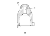
- FIG. 6 is a diagram schematically showing an AA line cross section of the second nozzle portion 44 shown in FIG.
- the second nozzle portion 44 is formed with an internal flow path 48 whose diameter decreases toward the tip of the nozzle.
- the second injection port 24 is provided so as to be bent at a substantially right angle from the small diameter portion on the tip end side of the internal flow path 48.
- the cleaning liquid is applied to the second convex curved surface 14. It is slightly diagonally downward to point.
- the second nozzle portion 44 of the cleaner device 10 is arranged outside the second convex curved surface 14, and the cleaning liquid is sprayed onto the second convex curved surface 14 in a fan shape.
- the injection port 24 is provided.
- the shape of the second injection port 24 is defined so that the fan-shaped cleaning liquid layer 28 to be sprayed has a shape that is convexly curved in the same direction as the second convex curved surface 14.
- the sprayed fan-shaped layer 28 of the cleaning liquid is adapted to the second convex curved surface 14 of the second camera 12, whereby more cleaning liquid can be sprayed on the second convex curved surface 14.
- FIG. 7 is a front view schematically showing the cleaner device 110 according to the embodiment.
- the cleaner device 110 shown in FIG. 7 is a vehicle cleaner device mounted on a vehicle such as an automobile in this embodiment.
- the cleaner device 110 is configured to clean a plurality of objects to be cleaned, for example, the first camera 111 and the second camera 112.
- the first camera 111 and the second camera 112 are arranged side by side and adjacent to each other, for example, as shown in the figure.
- the first camera 111 and the second camera 112 are installed in different postures so as to capture different directions, for example, in front of and behind the vehicle.
- the first camera 111 and the second camera 112 have different outer shapes
- the first camera 111 has a circular shape
- the second camera 112 has a rectangular shape. Has.
- the first camera 111 has a first surface 113 and the second camera 112 has a second surface 114.
- These surfaces to be cleaned are the surfaces of optical elements exposed to the outside, which are components of the camera.
- the optical element may be, for example, a lens, or may be a translucent lens cover for protecting the lens, or may be another optical element.
- the first surface 113 and the second surface 114 may be curved surfaces that are convexly curved toward the outside, such as a spherical surface, or may be a flat surface or other surface having a shape.
- the first surface 113 and the second surface 114 may have the same shape, but in general, they may have different shapes depending on the design and specifications of each camera.
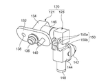
- the cleaner device 110 includes a nozzle assembly 120, and the nozzle assembly 120 is provided with a first nozzle portion 121 having a first injection port 122 and a second nozzle portion 123 having a second injection port 124.
- the nozzle assembly 120 has a substantially L-shaped shape in which a horizontally long first nozzle portion 121 and a vertically long second nozzle portion 123 are connected to each other.
- the cleaning liquid is supplied to the first nozzle unit 121 from a supply source such as a tank, and is supplied to the second nozzle unit 123 via the first nozzle unit 121.
- the cleaning liquid supplied to the first nozzle unit 121 is ejected from the first injection port 122, and the cleaning liquid supplied to the second nozzle unit 123 is injected from the second injection port 124.
- the first injection port 122 is arranged so as to inject the cleaning liquid onto the first surface 113
- the second injection port 124 is arranged so as to inject the cleaning liquid onto the second surface 114.
- the first injection port 122 is configured to inject the cleaning liquid into the first surface 113 in a fan shape
- the second injection port 124 is configured to inject the cleaning liquid into the second surface 114 in a fan shape.
- FIG. 7 shows a fan-shaped cleaning liquid layer 126 sprayed from the first injection port 122 onto the first surface 113 and sprayed from the second injection port 124 onto the second surface 114.
- a fan-shaped cleaning liquid layer 128 is shown.
- the nozzle assembly 120 is arranged outside the field of view of the first camera 111 and the second camera 112 so as not to interfere with the shooting or to minimize the influence on the shooting.
- the first nozzle portion 121 is arranged above the first camera 111, and the first injection port 122 injects the cleaning liquid downward toward the first surface 113.
- the second nozzle portion 123 is arranged between the first camera 111 and the second camera 112, and the second injection port 124 injects the cleaning liquid diagonally downward toward the second surface 114.
- the periphery of the first camera 111, the second camera 112, and the nozzle assembly 120 is covered with the cover member 116.
- a support member for supporting the first camera 111, the second camera 112, and the nozzle assembly 120 for example, the bracket 118 shown in FIG. 8A, is provided.
- a first camera 111, a second camera 112, and a nozzle assembly 120 are attached to the bracket 118.
- the cleaner device 110 is a vehicle cleaner device
- the first camera 111, the second camera 112, and the nozzle assembly 120 are supported by the vehicle body via the bracket 118.
- the first nozzle portion 121 not only has a role of spraying a cleaning liquid on the first surface 113 of the first camera 111, but is also provided as a fixing portion for fixing the nozzle assembly 120 to the bracket 118.
- the first nozzle portion 121 is fixed to the bracket 118 by, for example, a screw 30 as a fixing member.
- the first nozzle portion 121 may be fixed to the bracket 118 or the support member by other fixing means.
- Each part of the nozzle assembly 120 and the bracket 118 are made of an appropriate synthetic resin material such as polyacetal resin, acrylic resin, and polycarbonate resin.
- Each part of the nozzle assembly 120 and the bracket 118 are made of, for example, the same material, but may be made of different materials.
- the nozzle assembly 120 is combined with the bracket 118 to form a nozzle assembly for the object to be cleaned (that is, the first camera 111 and the second camera 112). It is configured to regulate the displacement of 120.
- the first nozzle portion 121 is fixed to the bracket 118
- the second nozzle portion 123 is connected to the first nozzle portion 121
- the displacement regulating structure of the nozzle assembly 120 is formed by the second nozzle portion 123 and the bracket 118. ..
- the second nozzle portion 123 and the bracket 118 are not directly fixed, but the second nozzle portion 123 and the bracket 118 are provided with a concave-convex shape that is combined with each other so as to suppress the movement of the nozzle assembly 120 with respect to the bracket 118 as a displacement control structure. There is.
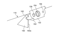
- FIG. 8 (a) is a perspective view schematically showing a state in which the nozzle assembly 120 of the cleaner device 110 shown in FIG. 7 is attached to the bracket 118
- FIG. 8 (b) is a perspective view in FIG. 8 (a). It is a partial cross-sectional view which cut out a part of the 2nd nozzle part 123 of a nozzle assembly 120. Note that in FIGS. 8A and 8B, the nozzle assembly 120 viewed from the second injection port 124 side of the second nozzle portion 123 with the cover member 116 shown in FIG. 7 removed is the bracket 118. Shown with some of. FIG. 8B shows a vertical cross section of the second nozzle portion 123.
- FIG. 9 is a perspective view showing the bracket 118 shown in FIG. 8A in a state where the nozzle assembly 120 is not attached.
- FIG. 10 is a perspective view schematically showing the nozzle assembly 120 shown in FIG. 8A from the back side.
- 11 (a) shows the FF cross section shown in FIG. 8 (a)
- FIG. 11 (b) shows the GG cross section shown in FIG. 11 (a).
- the first nozzle portion 121 is formed in a horizontally long substrate portion 132, an injection portion 134 formed in the front center portion of the substrate portion 132, and a back center portion of the substrate portion 132. It has an entrance portion 136.
- the injection unit 134 is provided with the first injection port 122 shown in FIG. 7.
- An internal flow path for guiding the cleaning liquid to the first injection port 122 and the second nozzle portion 123 is formed through the substrate portion 132 from the inlet portion 136 to the injection portion 134.
- a screw hole 138 is formed on one side of the injection portion 134, and a positioning pin 140 is formed on the opposite side of the injection portion 134.
- the screw hole 138 penetrates from the front surface to the back surface of the substrate portion 132.
- the positioning pin 140 is a rod-shaped protrusion protruding from the back surface of the substrate portion 132.
- the second nozzle unit 123 has a nozzle 142 having a second injection port 124 and a vertically long nozzle holder 144.
- the nozzle holder 144 has a connecting portion 146 for connecting the second nozzle portion 123 to the first nozzle portion 121, and a nozzle holding portion 147 shown in FIG. 11B.
- the connection portion 146 is formed on, for example, the upper part of the side surface of the nozzle holder 144, and is fitted into the injection portion 134 of the first nozzle portion 121 by, for example, press fitting, whereby the second nozzle portion 123 is coupled to the first nozzle portion 121. ..
- the nozzle holding portion 147 is formed in, for example, the central portion of the front surface of the nozzle holder 144.
- the nozzle 142 is fitted into the nozzle holding portion 147 by, for example, press fitting, whereby the nozzle 142 is mounted on the nozzle holder 144.
- the nozzle holder 144 is formed with an internal flow path for guiding the cleaning liquid from the connecting portion 146 to the nozzle holding portion 147. Therefore, the cleaning liquid can be flowed from the injection unit 134 of the first nozzle unit 121 to the second injection port 124 of the nozzle 142 through the internal flow path of the nozzle holder 144.
- a cap 148 is attached to the lower end of the nozzle holder 144 so that the cleaning liquid flowing through the internal flow path of the nozzle holder 144 does not flow out from the opening at the lower end of the nozzle holder 144, and this opening is closed by the cap 148. ..
- the nozzle holder 144 has a convex portion 150 as the above-mentioned displacement restricting structure, and the convex portion 150 is formed in, for example, the central portion of the back surface of the nozzle holder 144.
- the convex portion 150 has an H-shaped shape, and the two first vertical ribs 150a and the lateral portions connecting the first vertical ribs 150a at the central portion thereof. It has a rib 150b.
- the bracket 118 has a mounting portion 152 overhanging toward the front side.
- the mounting portion 152 has a mounting surface 153 that comes into contact with the back surface of the substrate portion 132 of the first nozzle portion 121 when the first nozzle portion 121 is mounted.
- a flow path 154 is opened in the central portion of the mounting surface 153, a screw hole 156 is formed on one side of the flow path 154, and a positioning hole 158 is formed on the opposite side of the injection portion 134.
- the flow path 154 is connected to a cleaning liquid supply source (not shown) including a cleaning liquid tank, a pump for delivering the cleaning liquid from the tank, and the like.
- the bracket 118 has a second vertical rib 160 protruding toward the front side.
- the second vertical rib 160 is formed at a position corresponding to the back of the second nozzle portion 123 when the nozzle assembly 120 is attached to the bracket 118.
- the second vertical rib 160 is provided with a recess 162 as the displacement restricting structure described above.
- the recess 162 is formed on the front end surface 160a of the second vertical rib 160 so as to regulate the displacement of the second nozzle portion 123 in at least one direction by combining with the convex portion 150 of the nozzle holder 144.
- the nozzle assembly 120 is fixed to the bracket 118 by fixing the first nozzle portion 121 to the mounting portion 152 of the bracket 118.
- the positioning pin 140 of the first nozzle portion 121 is inserted into the positioning hole 158 of the bracket 118, and the inlet portion 136 of the first nozzle portion 121 is fitted into the flow path 154 of the bracket 118.
- a screw 30 (see FIG. 7) is screwed into the screw hole 138 of the first nozzle portion 121 and the screw hole 156 of the bracket 118, and the first nozzle portion 121 is fixed to the mounting portion 152 of the bracket 118.
- the nozzle assembly 120 is fixed to the bracket 118 with one screw 30, the assembling work is relatively easy.
- the convex portion 150 of the second nozzle portion 123 is the concave portion 162 of the bracket 118 as shown in FIGS. 8 (b), 11 (a) and 11 (b). Enters. In this way, the convex portion 150 and the concave portion 162 are combined. Since the recess 162 is a notch formed in the second vertical rib 160, the convex portion 150 is vertically sandwiched by the second vertical rib 160 in the recess 162. At this time, there may be a slight gap between the convex portion 150 and the concave portion 162, or the convex portion 150 and the concave portion 162 may be in contact with each other at least a part of their surfaces.
- the convex portion 150 of the second nozzle portion 123 abuts on the second vertical rib 160 in the concave portion 162, whereby the bracket.
- the vertical displacement or movement of the second nozzle unit 123 with respect to 118 is restricted.
- the convex portion 150 of the nozzle assembly 120 and the concave portion 162 of the bracket 118 are not fixed to each other. By doing so, since it is only necessary to combine the convex portion 150 and the concave portion 162 without fixing them to each other, the assembling work becomes easy.
- the front end surface 160a of the second vertical rib 160 provided with the recess 162 faces the back surface of the second nozzle portion 123 on the lower side of the recess 162. There may be a slight gap between the front end surface 160a of the second vertical rib 160 and the back surface of the second nozzle portion 123, or they may be in contact with each other.
- the nozzle assembly 120 eg, the second nozzle portion 123
- the second nozzle portion 123 abuts on the front end surface 160a of the second vertical rib 160, whereby the second nozzle with respect to the bracket 118.
- the displacement or movement of the portion 123 in the front-rear direction is restricted.
- the two first vertical ribs 150a of the convex portion 150 are arranged apart from each other on both sides of the second vertical rib 160 of the bracket 118, and the two first vertical ribs 150a are each the first. 2 Not in contact with the vertical rib 160. Therefore, the displacement of the second nozzle portion 123 with respect to the bracket 118 in the left-right direction is allowed. However, instead of this, the second nozzle portion 123 with respect to the bracket 118 is brought into contact with or sufficiently close to the convex portion 150 and the concave portion 162 so as to sandwich the second vertical rib 160 between the two first vertical ribs 150a. Left-right displacement or movement of the may be restricted.
- the flow path 154 of the bracket 118 is connected to the first injection port 122 through the internal flow path of the first nozzle portion 121.
- the flow path 154 is connected to the second injection port 124 through the internal flow path of the first nozzle portion 121 and the second nozzle portion 123. Therefore, when the cleaner device 110 is operated, the cleaning liquid is ejected from the cleaning liquid supply source through the flow path 154, the first nozzle portion 121, and the second nozzle portion 123 from the first injection port 122 and the second injection port 124 (FIG. 8).
- the flow of the cleaning liquid is schematically shown by an arrow).
- a fan-shaped cleaning liquid layer 126 is sprayed from the first injection port 122 onto the first surface 113 of the first camera 111, and a fan-shaped cleaning liquid layer 128 is sprayed from the second injection port 124 onto the second surface 114 of the second camera 112. Is sprayed on.
- the cleaner device 110 can clean the first camera 111 and the second camera 112 with a cleaning liquid, as shown in FIG.
- an external force may be applied to the nozzle assembly 120, such as a worker's hand accidentally hitting the nozzle assembly 120. If such an accidental external force is large, unintended movement or misalignment may occur in the nozzle assembly 120.
- the portion of the nozzle assembly 120 on which such an accidental external force acts is relatively far from the fixing portion of the nozzle assembly 120 to the bracket 118, that is, the first nozzle portion 121, for example, the second nozzle portion 123.
- the torque applied by this external force may increase, resulting in unintended movement or misalignment in the nozzle assembly 120.
- first injection port 122 or the second injection port 124 may be displaced from the correct position. If the direction of injection of the cleaning liquid from the nozzle is changed due to the misalignment of the injection port, it may be difficult for the cleaning fluid to hit the first camera 111 or the second camera 112, and cleaning may not be successful.
- the nozzle assembly 120 of the cleaner device 110 has a fixing portion, that is, a first nozzle portion 121, which is fixed to the bracket 118 at a portion different from the recess 162 of the bracket 118, and a recess of the bracket 118. It comprises a protrusion 150 that, when combined with 162, regulates the displacement of the nozzle assembly 120 with respect to the first camera 111 and the second camera 112.
- the convex portion 150 is formed on the second nozzle portion 123.
- the nozzle assembly is not only secured to the bracket 118 to which the first camera 111 and the second camera 112 are attached, but is also combined with the recess 162 and the protrusion 150 of the bracket 118, thereby the first.
- the displacement of the nozzle assembly 120 with respect to the camera 111 and the second camera 112 is restricted. Therefore, the misalignment of the first injection port 122 and the second injection port 124 due to an accidental external force is prevented or sufficiently suppressed.
- the first injection port 122 and the second injection port 124 can be held in the correct positions.
- the cleaner device 170 is common to the cleaner device 110 shown in FIG. 7 in that it is provided for cleaning the first camera 111 and the second camera 112, but differs in terms of nozzle configuration and displacement control structure.
- FIG. 12 is a front view schematically showing the cleaner device 170 according to another embodiment.
- 13 (a) is a perspective view schematically showing a state in which the nozzle assembly 171 of the cleaner device 170 shown in FIG. 12 is attached to the bracket 175, and
- FIG. 13 (b) is a perspective view in FIG. 13 (a). It is a partial cross-sectional view which cut out a part of the nozzle assembly 171. Note that FIGS. 13 (a) and 13 (b) show the nozzle assembly 171 together with a part of the bracket 175 with the cover member 174 shown in FIG. 12 removed.
- FIG. 14 is a perspective view showing the bracket 175 shown in FIG. 13A in a state where the nozzle assembly 171 is not attached.
- FIG. 15 is a perspective view schematically showing the nozzle assembly 171 shown in FIG. 13A from the back side.
- FIG. 16 shows a cross section taken along the line AA shown in FIG. 13 (a).
- the cleaner device 110 includes a nozzle 172, and the nozzle 172 is provided with a plurality of injection ports for injecting cleaning liquids in different directions, for example, a first injection port 122 and a second injection port 124.
- the first injection port 122 is arranged so as to inject the cleaning liquid onto the first surface 113 of the first camera 111
- the second injection port 124 is arranged so as to inject the cleaning liquid onto the second surface 114 of the second camera 112. Has been done.
- the nozzle 172 is installed between the first camera 111 and the second camera 112. As shown in FIG. 12, the first camera 111 is to the right of the nozzle 172 and the second camera 112 is to the left of the nozzle 172. Therefore, the first injection port 122 and the second injection port 124 are provided on the nozzle 172 so as to inject the cleaning liquid in substantially opposite directions to each other.
- the tip of the nozzle 172 has a conical shape, and the first injection port 122 and the second injection port 124 are opened on the conical side surface thereof.
- the first injection port 122 and the second injection port 124 are provided on one side and the other side with respect to the center of the nozzle 172.
- the first injection port 122 is configured to inject the cleaning liquid into the first surface 113 in a fan shape
- the second injection port 124 is configured to inject the cleaning liquid into the second surface 114 in a fan shape.
- FIG. 12 shows a fan-shaped cleaning liquid layer 126 sprayed from the first injection port 122 to the first surface 113 and sprayed from the second injection port 124 to the second surface 114.
- a fan-shaped cleaning liquid layer 128 is shown.
- the periphery of the first camera 111, the second camera 112, and the nozzle 172 is covered with the cover member 174.
- a support member for supporting the first camera 111, the second camera 112, and the nozzle assembly 171 is provided, for example, the bracket 175 shown in FIG. 13 (a).
- a first camera 111, a second camera 112, and a nozzle assembly 171 are attached to the bracket 175.
- the cleaner device 110 is a vehicle cleaner device
- the first camera 111, the second camera 112, and the nozzle assembly 171 are supported by the vehicle body via the bracket 175.
- the nozzle assembly 171 includes a nozzle 172 and a nozzle holder 173.
- the nozzle 172 is mounted on the front surface of the nozzle holder 173.
- the nozzle 172 and the nozzle holder 173 are formed of an appropriate synthetic resin material such as a polyacetal resin, an acrylic resin, or a polycarbonate resin.
- a connection hose 176 is connected to the lower end of the nozzle holder 173.
- the connection hose 176 is connected to the flow path of the cleaning liquid in the nozzle holder 173, and further, the flow path in the nozzle holder 173 is connected to the first injection port 122 and the second injection port 124 through the internal flow path of the nozzle 172.
- the connection hose 176 is connected to a cleaning liquid supply source including a cleaning liquid tank, a pump for delivering the cleaning liquid from the tank, and the like.
- the cleaning liquid is injected from the cleaning liquid supply source through the internal flow paths of the connecting hose 176, the nozzle holder 173, and the nozzle 172 from the first injection port 122 and the second injection port 124.
- the fan-shaped cleaning liquid layer 126 is sprayed onto the first surface 113 from the first injection port 122, and the fan-shaped cleaning liquid layer 128 is sprayed from the second injection port 124 onto the second surface. It is sprayed on 114.
- the cleaner device 170 can clean the first camera 111 and the second camera 112 with a cleaning liquid.
- the nozzle holder 173 has a fixing portion 177 and a recess 178 as a displacement regulating structure, as shown in FIG. 15, for example.
- the fixing portion 177 is formed at the upper end portion of the nozzle holder 173, and the screw hole 179 penetrates from the front surface to the back surface.
- the recess 178 is formed on the back surface of the nozzle holder 173 on the side opposite to the nozzle 172.
- the bracket 175 has a mounting portion 181 in which a screw hole 180 is formed, and a convex portion 182 as a displacement restricting structure.
- the convex portion 182 is provided so as to project toward the front side with respect to the mounting portion 181.
- the protrusion 182 is configured to regulate displacement of the nozzle assembly 171 in at least one direction by combining with the recess 178 of the nozzle holder 173.
- the bracket 175 is not provided with a flow path for the cleaning liquid.
- a screw 83 as a fixing member is screwed into the screw hole 179 of the fixing portion 177 and the screw hole 180 of the mounting portion 181, and the fixing portion 177 of the nozzle holder 173 is fixed to the mounting portion 181 of the bracket 175.
- the concave portion 178 of the nozzle holder 173 is inserted into the convex portion 182 of the bracket 175, and the convex portion 182 and the concave portion 178 are combined.
- the nozzle assembly 171 is fixed to the bracket 175.
- the nozzle holder 173 When an external force acts on the nozzle assembly 171 in the vertical direction, the nozzle holder 173 abuts on the convex portion 182 of the bracket 175 in the recess 178, thereby restricting the vertical displacement or movement of the nozzle assembly 171 with respect to the bracket 175. Nozzle. Similarly, the lateral and anteroposterior displacement of the nozzle assembly 171 with respect to the bracket 175 is also regulated.
- the convex portion 182 when the convex portion 182 is arranged in the concave portion 178, the convex portion 182 comes into contact with the protrusion 184 formed in the concave portion 178.
- Contact between the protrusion 182 and the protrusion 184 in the recess 178 positions the nozzle assembly 171 with respect to the bracket 175, thereby causing the first injection port 122 and the second injection port 124 to be the first camera 111 and the second, respectively. It can be accurately positioned with respect to the camera 112.
- the nozzle assembly 171 of the cleaner device 170 includes a fixing portion 177 fixed to the bracket 175 at a portion different from the convex portion 182 of the bracket 175, and a convex portion 182 of the bracket 175.
- a recess 178 that, when combined, regulates the displacement of the nozzle assembly 171 with respect to the first camera 111 and the second camera 112.
- the recess 178 is formed in the nozzle holder 173.
- the nozzle assembly 171 is not only fixed to the bracket 175 to which the first camera 111 and the second camera 112 are attached, but is also combined by the convex portions 182 and the concave portions 178 of the bracket 175, whereby the first camera assembly 171 is fixed.
- the displacement of the nozzle assembly 171 with respect to the 1st camera 111 and the 2nd camera 112 is restricted. Therefore, the misalignment of the first injection port 122 and the second injection port 124 due to an accidental external force is prevented or sufficiently suppressed.
- the first injection port 122 and the second injection port 124 can be held in the correct positions.
- the concave portion 178 of the nozzle assembly 171 and the convex portion 182 of the bracket 175 are not fixed to each other. In this way, the convex portion 182 and the concave portion 178 need only be combined without being fixed to each other, so that the assembling work becomes easy.
- the present invention is not limited to the above-described embodiments and modifications, and it is possible to combine embodiments and modifications, and to make further modifications such as various design changes based on the knowledge of those skilled in the art.
- the present invention also includes embodiments and modifications in which such combinations or further modifications are added.
- the above-mentioned embodiments and modifications, and the new embodiments resulting from the combination of the above-mentioned embodiments and modifications and the following modifications combine the effects of the combined embodiments, modifications and further modifications. Have.
- the upper edge 24a and the lower edge 24b of the second injection port 24 are convexly curved in the same direction as the second convex curved surface 14, but the present invention is not limited to this. At least one of the upper edge 24a and the lower edge 24b of the second injection port 24, for example, at least the upper edge 24a may be curved convexly in accordance with the second convex curved surface 14.
- one of the first injection port 22 and the second injection port 24, specifically, the shape of the second injection port 24 is convexly curved in accordance with the second convex curved surface 14.
- both the first injection port 22 and the second injection port 24 may be curved convexly. Therefore, the nozzle is provided with a plurality of injection ports, and each of the plurality of injection ports so as to inject the cleaning fluid into a fan shape on the corresponding convex curved surface among the plurality of convex curved surfaces arranged around the nozzle. It may be arranged.
- the shape of each injection port is defined so that the fan-shaped cleaning fluid layer injected from the injection port has a shape that is convexly curved in the same direction as the convex curved surface corresponding to the injection port. May be good.
- the plurality of injection ports are arranged so as to inject the cleaning liquid onto different objects to be cleaned.
- the plurality of injection ports are arranged to inject the cleaning liquid to different parts of the same object to be cleaned or to the same part of the same object to be cleaned from different directions. good.
- the number of injection ports is not particularly limited. Three or more injection ports may be provided, or only one may be provided.
- the arrangement and shape of the convex and concave portions as the displacement regulation structure are not limited to the above-mentioned specific form, and may take various other forms.
- an H-shaped convex portion 150 having two first vertical ribs 150a and one horizontal rib 150b is used.
- the convex portion 150 may have only the horizontal rib 150b without the first vertical rib 150a.
- the convex portion 150 is formed on the back surface of the nozzle holder 144, but instead of the convex portion 150, for example, a convex portion is formed on the side surface of the nozzle holder 144 (the surface on the same side as the connection portion 146 or the surface on the opposite side). Is formed, and a concave portion to be combined with the convex portion may be formed in the bracket 118.
- a concave portion may be provided instead of the convex portion.
- a convex portion may be provided instead of the concave portion.
- a concave portion is formed in the nozzle assembly 120, a convex portion is formed in the bracket 118, and the concave portion and the convex portion are formed.
- a displacement regulation structure may be formed.
- a convex portion is formed in the nozzle assembly 171 and a concave portion is formed in the bracket 175, and the convex portion and the concave portion are combined.
- the displacement regulation structure may be formed by.
- the nozzle having the injection port and the nozzle holder are prepared as separate parts, and the nozzle is mounted on the nozzle holder.
- one nozzle component in which the nozzle and the nozzle holder are integrally molded may be used.
- the shape of one or both of the first injection port 122 and the second injection port 124 is the same as that of the embodiment described with reference to FIG. May be defined so that the sprayed fan-shaped layer of cleaning liquid has a shape that is convexly curved in the same direction as the convex curved surface of the object to be cleaned.
- the cleaning fluid is a cleaning fluid
- the cleaning fluid may be a gas such as air.
- the vehicle cleaner device for cleaning the in-vehicle camera is described as an example, but the object to be cleaned by the cleaner devices 10 and 110 is an in-vehicle camera such as a distance measuring sensor such as LiDAR. It may be an in-vehicle sensor other than the above, or it may be another in-vehicle device.
- the optical element to be cleaned may form a part of an in-vehicle device to be cleaned.
- the cleaner devices 10 and 110 are not limited to those for vehicles.
- the cleaner device according to the embodiment can be mounted on an outdoor lighting device such as a street light, a sensor device, or various other devices, and for cleaning various objects to be cleaned provided in such a device. May be used for.
- the present invention can be used for a nozzle and a cleaner device including the nozzle.
Abstract
クリーナ装置(10)のノズル(20)は、第2凸状曲面(14)をもつ第2カメラ(12)を洗浄する。ノズル(20)は、第2凸状曲面(14)の外側に配置され、第2凸状曲面(14)に洗浄流体を扇形状に噴射する第2噴射口(24)を備える。第2噴射口(24)の形状は、噴射される扇形状の洗浄流体の層(28)が第2凸状曲面(14)と同じ方向に向かって凸に湾曲した形状をもつように定められている。
Description
本発明は、ノズルおよびこれを備えるクリーナ装置に関する。また、本発明は、ノズルアセンブリおよびこれを備えるクリーナ装置に関する。
従来、車両のフロントウィンドウを洗浄するウィンドウォッシャや、ヘッドランプを洗浄するランプクリーナなど、種々の洗浄装置を車両に搭載することが知られている。また、こうした洗浄装置に加えてカメラやLiDARなど車載センサを洗浄するセンサクリーナを統合した使い勝手のよい車両用クリーナシステムが提案されている(例えば、特許文献1参照。)。
本発明者らは、上記の車両用クリーナシステムについて検討したところ、以下の課題を認識するに至った。被洗浄物は、例えばカメラのレンズ面のように、しばしば球面など凸状曲面をもつ。被洗浄物の正面にノズルを配置すれば洗浄流体を確実に吹き付けることが容易である反面、被洗浄物にとっての視界がノズルによって妨げられうる。これを避けるべく、被洗浄物の凸状曲面に向けてノズルから横向きまたは斜めに洗浄流体を噴射するように、ノズルが被洗浄物の例えば側方に配置されることがある。この場合、ノズルから噴射される洗浄流体の一部が被洗浄物の凸状曲面から逸れて当たらず、被洗浄物の近傍を通り過ぎてしまうことがあるかもしれない。被洗浄物に当たらずに通過した洗浄流体は、洗浄に寄与せず無駄になる。この洗浄流体は単に周囲に噴射されるにすぎないので、洗浄流体が液体の場合には特に、周囲への飛散も懸念される。同様の問題は、車両用クリーナシステムだけではなく、そのほか一般用途のクリーナ装置でも起こりうる。
本発明のある態様はこうした状況に鑑みてなされたものであり、その例示的な目的のひとつは、被洗浄物に洗浄流体をより多く吹き付けることのできるノズルおよびこれを備えるクリーナ装置を提供することにある。
組み付け作業の際に作業者の手が偶然当たる等、クリーナ装置のノズルに外力が加えられたとき、ノズルの固定の仕方によっては、ノズルが正しい位置からずれてしまう可能性がある。そのようなノズルの位置ずれにより、もしノズルからの洗浄流体の噴射方向が変わってしまったとすると、被洗浄物に洗浄流体が当たりにくくなり、うまく洗浄できなくなってしまうかもしれない。
本発明のある態様はこうした状況に鑑みてなされたものであり、その例示的な目的のひとつは、洗浄流体の噴射口を正しい位置に保持するための構造を有するノズルアセンブリを提供することにある。
本発明のある態様は、凸状曲面をもつ被洗浄物を洗浄するクリーナ装置のノズルに関する。ノズルは、凸状曲面の外側に配置され、凸状曲面に洗浄流体を扇形状に噴射する噴射口を備える。噴射口の形状は、噴射される扇形状の洗浄流体の層が凸状曲面と同じ方向に向かって凸に湾曲した形状をもつように定められている。
この態様によると、噴射される扇形状の洗浄流体の層を被洗浄物の凸状曲面に適合させ、それにより、被洗浄物に洗浄流体をより多く吹き付けることができる。また、被洗浄物に当たらずに周囲に飛散する洗浄流体を減らすことができる。
噴射口の上縁および下縁が、ノズルの先端に向かって凸に湾曲していてもよい。このようにすれば、噴射される扇形状の洗浄流体の層に、凸に湾曲した形状を容易に与えることができる。
噴射口は、噴射される扇形状の洗浄流体の層が、凸状曲面の中心に対して一方側で凸状曲面に当たり、凸状曲面に沿って凸状曲面の中心を越えて他方側へと流れるように配置されていてもよい。このようにすれば、凸状曲面の比較的広い範囲に洗浄流体を流すことができ、これは被洗浄物の良好な洗浄につながる。
噴射口は、噴射される扇形状の洗浄流体の層の両端がそれぞれ、凸状曲面の周縁に向かうように構成されていてもよい。このようにすれば、凸状曲面の周縁よりも外側へと飛散する洗浄流体を減らすことができる。
ノズルは、複数の噴射口を備え、複数の噴射口はそれぞれが、ノズルの周囲に配置される複数の凸状曲面のうち対応する凸状曲面に洗浄流体を扇形状に噴射するように配置されていてもよい。各噴射口の形状は、当該噴射口から噴射される扇形状の洗浄流体の層が当該噴射口に対応する凸状曲面と同じ方向に向かって凸に湾曲した形状をもつように定められていてもよい。このようにすれば、複数の噴射口により、複数の被洗浄物(または同一の被洗浄物の複数の部位)を洗浄することができる。各噴射口について、噴射される扇形状の洗浄流体の層を対応する凸状曲面に適合させ、それにより、被洗浄物に洗浄流体をより多く吹き付けることができる。また、被洗浄物に当たらずに周囲に飛散する洗浄流体を減らすことができる。
本発明の別の態様は、クリーナ装置に関する。クリーナ装置は、上記のいずれかの態様のノズルを備えてもよい。凸状曲面は、光学素子の表面であってもよい。
クリーナ装置は、車両に取り付けられてもよい。光学素子は、被洗浄物である車載機器の一部を構成してもよい。
本発明のある態様のクリーナ装置のノズルアセンブリは、被洗浄物が取り付けられるブラケットによって支持される。ブラケットは、凹部または凸部を有する。ノズルアセンブリは、ブラケットの凹部または凸部とは異なる部位でブラケットに固定される固定部と、ブラケットの凹部または凸部と組み合わさることによって被洗浄物に対するノズルアセンブリの変位を規制する凸部または凹部と、を備える。
この態様によると、ノズルアセンブリは、被洗浄物が取り付けられるブラケットに固定されるだけでなく、凸部(または凹部)でこのブラケットの凹部(または凸部)と組み合わされ、それにより、被洗浄物に対するノズルアセンブリの変位が規制される。したがって、偶発的な外力によるノズルの位置ずれは防止され、または十分に抑制され、ノズルを正しい位置に保持することができる。
固定部は、洗浄流体の第1噴射口を有する第1ノズル部として設けられ、第1ノズル部には、洗浄流体の第2噴射口を有する第2ノズル部が接続され、凸部または凹部は、第2ノズル部に形成されていてもよい。このようにすれば、第1ノズル部はブラケットに固定され、第2ノズル部は凸部(または凹部)でブラケットの凹部(または凸部)と組み合わされ、それにより、第1ノズル部と第2ノズル部の両方を正しい位置に保持することができる。
ノズルアセンブリは、それぞれが異なる方向に洗浄流体を噴射する第1噴射口および第2噴射口を有するノズルと、ノズルが装着され、固定部と凸部または凹部とを有するノズルホルダと、を備えてもよい。このようにすれば、ノズルホルダは、ブラケットに固定されるとともに、凸部(または凹部)でこのブラケットの凹部(または凸部)と組み合わされる。第1噴射口および第2噴射口を有するノズルがこのようなノズルホルダに装着されているので、各噴射口を対応する被洗浄物に対して正しい位置に保持することができる。
ノズルアセンブリの凸部または凹部とブラケットの凹部または凸部とは、互いに固定されていなくてもよい。このようにすれば、凸部(または凹部)と凹部(または凸部)を互いに固定することなく組み合わせるだけでよいので、組み付け作業が容易になる。
本発明の別の態様は、クリーナ装置に関する。クリーナ装置は、上記のいずれかの態様のノズルアセンブリを備えてもよい。
クリーナ装置は、車両に取り付けられてもよい。被洗浄物は、車載機器であってもよい。
本発明のある態様によれば、被洗浄物に洗浄流体をより多く吹き付けることができる。本発明のある態様によれば、洗浄流体の噴射口を正しい位置に保持するための構造を有するノズルアセンブリを提供することができる。
以下、本発明を好適な実施の形態をもとに図面を参照しながら説明する。実施の形態は、発明を限定するものではなく例示であって、実施の形態に記述されるすべての特徴やその組み合わせは、必ずしも発明の本質的なものであるとは限らない。各図面に示される同一または同等の構成要素、部材、処理には、同一の符号を付するものとし、適宜重複した説明は省略する。また、各図に示す各部の縮尺や形状は、説明を容易にするために便宜的に設定されており、特に言及がない限り限定的に解釈されるものではない。また、本明細書または請求項中に用いられる「第1」、「第2」等の用語は、いかなる順序や重要度を表すものでもなく、ある構成と他の構成とを区別するためのものである。また、各図面において実施の形態を説明する上で重要ではない部材の一部は省略して表示する。
図1は、実施の形態に係るクリーナ装置10を模式的に示す正面図である。図1に示されるクリーナ装置10は、この実施の形態では、自動車などの車両に搭載される車両用クリーナ装置である。
クリーナ装置10は、複数の被洗浄物、例えば第1カメラ11と第2カメラ12を洗浄するように構成される。第1カメラ11と第2カメラ12は、例えば、図示されるように、横並びに隣接して配置される。第1カメラ11と第2カメラ12は、例えば車両の前方と後方など、異なる方向を撮影するように異なる姿勢で設置されている。図示されるように、この例では、第1カメラ11と第2カメラ12は異なる外形を有し、第1カメラ11は、円形状の形状を有し、第2カメラ12は、方形状の形状を有する。
クリーナ装置10によって洗浄されるべき表面として、第1カメラ11は、第1凸状曲面13を有し、第2カメラ12は、第2凸状曲面14を有する。これら凸状曲面は、カメラの構成要素である外部に露出された光学素子の表面である。光学素子は、例えばレンズであり、またはレンズを保護するための透光性をもつレンズカバーであってもよく、あるいは、その他の光学素子であってもよい。第1凸状曲面13と第2凸状曲面14も、各カメラの設計と仕様に応じた異なる形状をとりうる。
凸状曲面は、例えば球面の一部である。ただし、凸状曲面は、例えば放物面など他の二次曲面、または非球面など、外部に向かって凸に湾曲しているその他の形状の曲面であってもよい。なお、凸状曲面は、その全面が曲面であるものには限られず、全体として外に向かって凸に見える形状であってもよく、その一部に平坦な領域が含まれてもよい。
クリーナ装置10は、ノズル20を備え、ノズル20には、互いに異なる方向に洗浄液を噴射する複数の噴射口、例えば第1噴射口22と第2噴射口24が設けられている。これら複数の噴射口は、ノズル20の周囲に配置される複数の凸状曲面のうち対応する凸状曲面に洗浄液を噴射するように配置されている。具体的には、第1噴射口22は、第1凸状曲面13に洗浄液を噴射するように配置され、第2噴射口24は、第2凸状曲面14に洗浄液を噴射するように配置されている。
ノズル20は、第1カメラ11と第2カメラ12による撮影を妨げないように、または撮影への影響を最小限とするように、これらカメラの視界の外、例えば第1カメラ11および第2カメラ12の側方に配置されている。第1噴射口22は、第1凸状曲面13の外側に配置され、第2噴射口24は、第2凸状曲面14の外側に配置されている。
この実施の形態では、ノズル20が第1カメラ11と第2カメラ12の間に設置されている。図1に示されるように、第1カメラ11がノズル20の向かって右に、第2カメラ12がノズル20の向かって左にある。第1凸状曲面13は、ノズル20に対して一方側に位置し、第2凸状曲面14は、ノズル20に対して他方側に位置する。そのため、第1噴射口22と第2噴射口24は互いに概ね反対方向に洗浄液を噴射するようにノズル20に設けられている。ノズル20の先端部は円すい状の形状を有し、その円すい状の側面に第1噴射口22と第2噴射口24が開口している。第1噴射口22と第2噴射口24は、ノズル20の中心に対して一方側と他方側に設けられている。
第1噴射口22は、第1凸状曲面13に洗浄液を扇形状に噴射するように構成され、第2噴射口24は、第2凸状曲面14に洗浄液を扇形状に噴射するように構成されている。理解を容易にするために、図1には、第1噴射口22から第1凸状曲面13に噴射される扇形状の洗浄液の層26と、第2噴射口24から第2凸状曲面14に噴射される扇形状の洗浄液の層28を示す。
また、詳細は後述するが、第1噴射口22と第2噴射口24のうち一方または両方の形状は、噴射される扇形状の洗浄液の層が凸状曲面と同じ方向に向かって凸に湾曲した形状をもつように定められていてもよい。この実施の形態では、例えば、噴射される扇形状の洗浄液の層28が第2凸状曲面14と同じ方向に向かって凸に湾曲した形状をもつように、第2噴射口24の形状が定められている。
図1に示されるように、第1カメラ11、第2カメラ12、およびノズル20の周囲は、カバー部材16で覆われている。よって、クリーナ装置10のノズル20以外の部分は、カバー部材16によって覆い隠されている。
図2は、図1に示されるクリーナ装置10のノズルアセンブリ30の取付状態を模式的に示す斜視図である。なお図2には、図1に示されるカバー部材16を取り外した状態が示されている。よって、図2には、カバー部材16の背後に配置されたブラケット18の一部とともに、ノズル20の第2噴射口24側から見たノズルアセンブリ30が示されている。
ノズルアセンブリ30は、ノズル20とノズルホルダ32とを備える。ノズル20は、ノズルホルダ32に装着されている。ノズル20とノズルホルダ32は、例えばポリアセタール樹脂、アクリル樹脂、ポリカーボネート樹脂など、適宜の合成樹脂材料で形成される。
ノズルホルダ32は、ブラケット18に例えばねじ34で固定されている。他の固定手段によりノズルホルダ32がブラケット18に固定されてもよい。上述のように、この実施の形態では、クリーナ装置10は車両用クリーナ装置であるから、ノズルアセンブリ30は、ブラケット18を介して車体に支持される。図示を省略するが、ブラケット18には、ノズルアセンブリ30だけでなく、第1カメラ11と第2カメラ12も取り付けられていてもよい。
ノズルホルダ32には、接続ホース36が接続されている。接続ホース36は、ノズルホルダ32内の洗浄液の流路に接続され、さらに、このノズルホルダ32内の流路がノズル20の内部流路を通じて第1噴射口22と第2噴射口24に接続されている。また、接続ホース36は、洗浄液タンクや洗浄液をタンクから送出するためのポンプなどを含む洗浄液供給源に接続されている。
したがって、クリーナ装置10の作動時には、洗浄液供給源から接続ホース36、ノズルホルダ32およびノズル20の内部流路を通じて、第1噴射口22と第2噴射口24から洗浄液が噴射される。それにより、図1に示されるように、第1噴射口22から扇形状の洗浄液の層26が第1凸状曲面13に吹き付けられ、第2噴射口24から扇形状の洗浄液の層28が第2凸状曲面14に吹き付けられる。
図3(a)および図3(b)は、ノズル20の第1噴射口22とそこから第1カメラ11の第1凸状曲面13に噴射される扇形状の洗浄液の層26を模式的に示す斜視図である。図3(a)には、ノズル20の第1噴射口22に対して第1カメラ11の第1凸状曲面13が手前にくる方向から見たときの第1噴射口22を第1凸状曲面13および洗浄液の層26とともに拡大して示し、図3(b)には、同じ方向から図3(a)に比べて離れた視点からノズル20を見たときの洗浄液の層26の形状を示す。図3(a)および図3(b)では便宜上、ノズル20の中心軸21を上下方向として示す。
第1カメラ11は、ノズル20の中心軸21に対して若干傾いて設置されており、第1凸状曲面13も中心軸21に垂直な平面に対して若干傾いている。図示されるように、第1凸状曲面13は、右下がりに緩やかに傾斜している。第1凸状曲面13は、中心13aと周縁13bを有する。第1凸状曲面13は上述のように、外に向かって(図3(a)では上に向かって)凸に湾曲しているから、中心13aは周縁13bに対して外側(上側)に張り出している。この例では、中心13aは外側に最も張り出している第1凸状曲面13の頂点にあたり、周縁13bは中心13aを中心とする円を描く。第1凸状曲面13は、緩やかな湾曲面であり、周縁13bに対する中心13aの高さは、周縁13bの半径より小さい。
第1噴射口22は、直線状の上縁22a、下縁22b、左縁22c、右縁22dを有し、全体として角に丸みを帯びた四角形状の形状を有する。上縁22aと下縁22bは互いに、左縁22cおよび右縁22dによって接続されている。上縁22aおよび下縁22bは、左縁22cおよび右縁22dに比べていくらか長く、第1噴射口22は、横向きに細長くなっている。
上述のように傾斜して配置された第1凸状曲面13に、第1噴射口22からの扇形状の洗浄液の層26を適合させるために、第1噴射口22は、同様に傾斜した形状をもつ。よって、上縁22aおよび下縁22bは、第1凸状曲面13と同様に右下がりに緩やかに傾斜している。第1噴射口22の上縁22aと下縁22bは概ね互いに平行に延びているので、第1噴射口22からの扇形状の洗浄液の層26は、図3(b)に示されるように、平面状の液層を形成する。
第1噴射口22は、第1凸状曲面13の側方(図3(a)では後方)に配置され、第1凸状曲面13よりもやや上方に位置する。第1噴射口22の上縁22aおよび下縁22bは、第1凸状曲面13の中心13aよりも上方に位置する。よって、洗浄液の層26は、第1噴射口22から第1凸状曲面13に向けて斜め下向きに噴射される。
また、第1噴射口22は、噴射される扇形状の洗浄液の層26が、第1凸状曲面13の中心13aに対して一方側(図3(a)において奥側)で第1凸状曲面13に当たり、第1凸状曲面13に沿って第1凸状曲面13の中心13aを越えて他方側(図3(a)において手前側)へと流れるように配置されている。このようにして、第1凸状曲面13の比較的広い範囲(例えば第1凸状曲面13のほぼ全域)に洗浄液を流すことができ、第1凸状曲面13の良好な洗浄につながる。
また、第1噴射口22の奥から手前に向かって、第1噴射口22の左縁22cと右縁22dとの間隔は、徐々に広がっている。このような第1噴射口22の横方向の広がりにより、第1噴射口22から噴射される洗浄液の層26は、横方向に扇形状に広がることになる。
第1噴射口22は、噴射される扇形状の洗浄液の層26の両端26bがそれぞれ、第1凸状曲面13の周縁13bに向かうように構成されている。図3(a)に示されるように、第1噴射口22から噴射される扇形状の洗浄液の層26の両端26bは、左縁22cと右縁22dそれぞれからいわば接線のように第1凸状曲面13の周縁13bを通過するようにして、第1凸状曲面13に吹き付けられている。そのため、第1凸状曲面13の周縁13bよりも外側へと飛散する洗浄液を減らすことができる。
図4(a)および図4(b)は、ノズル20の第2噴射口24とそこから第2カメラ12の第2凸状曲面14に噴射される扇形状の洗浄液の層28を模式的に示す斜視図である。図4(a)には、ノズル20の第2噴射口24に対して第2カメラ12の第2凸状曲面14が手前にくる方向から見たときの第2噴射口24を第2凸状曲面14および洗浄液の層28とともに拡大して示し、図4(b)には、同じ方向から図4(a)に比べて離れた視点からノズル20を見たときの洗浄液の層28の形状を示す。図4(a)および図4(b)では便宜上、ノズル20の中心軸21を上下方向として示す。
第2カメラ12は、ノズル20の中心軸21に沿って設置されており、第2凸状曲面14は、中心軸21に垂直な平面に沿って配置されている。第2凸状曲面14は、中心14aと周縁14bを有する。第2凸状曲面14は上述のように、外に向かって(図4(a)では上に向かって)凸に湾曲しているから、中心14aは周縁14bに対して外側(上側)に張り出している。この例では、中心14aは外側に最も張り出している第2凸状曲面14の頂点にあたり、周縁14bは中心14aを中心とする円を描く。第2凸状曲面14は、緩やかな湾曲面であり、周縁14bに対する中心14aの高さは、周縁14bの半径より小さい。
第2噴射口24の形状は、噴射される扇形状の洗浄液の層28が第2凸状曲面14と同じ方向に向かって凸に湾曲した形状をもつように定められている。そのために、第2噴射口24の上縁24aおよび下縁24bが、ノズル20の先端に向かって凸に湾曲している。このようにすれば、図4(b)に示されるように、噴射される扇形状の洗浄液の層28に、凸に湾曲した形状を容易に与えることができる。
また、第2噴射口24は、直線状の左縁24cおよび右縁24dを有し、上縁24aと下縁24bは互いに、左縁24cおよび右縁24dによって接続されている。上縁24aおよび下縁24bは、左縁24cおよび右縁24dに比べていくらか長く、第2噴射口24は、横向きに細長くなっている。
第2噴射口24は、第2凸状曲面14の側方(図4(a)では後方)に配置され、第2凸状曲面14よりもやや上方に位置する。第2噴射口24の上縁24aおよび下縁24bは、第2凸状曲面14の中心14aよりも上方に位置する。よって、洗浄液の層28は、第2噴射口24から第2凸状曲面14に向けて斜め下向きに噴射される。
また、第2噴射口24は、噴射される扇形状の洗浄液の層28が、第2凸状曲面14の中心14aに対して一方側(図4(a)において奥側)で第2凸状曲面14に当たり、第2凸状曲面14に沿って第2凸状曲面14の中心14aを越えて他方側(図4(a)において手前側)へと流れるように配置されている。このようにして、第2凸状曲面14の比較的広い範囲(例えば第2凸状曲面14のほぼ全域)に洗浄液を流すことができ、第2凸状曲面14の良好な洗浄につながる。
また、第2噴射口24の奥から手前に向かって、第2噴射口24の左縁24cと右縁24dとの間隔は、徐々に広がっている。このような第2噴射口24の横方向の広がりにより、第2噴射口24から噴射される洗浄液の層28は、横方向に扇形状に広がることになる。
第2噴射口24は、噴射される扇形状の洗浄液の層28の両端28bがそれぞれ、第2凸状曲面14の周縁14bに向かうように構成されている。図4(a)に示されるように、第2噴射口24から噴射される扇形状の洗浄液の層28の両端28bは、左縁24cと右縁24dそれぞれからいわば接線のように第2凸状曲面14の周縁14bを通過するようにして、第2凸状曲面14に吹き付けられている。そのため、第2凸状曲面14の周縁14bよりも外側へと飛散する洗浄液を減らすことができる。
以上に説明したように、実施の形態に係るクリーナ装置10のノズル20は、第2凸状曲面14の外側に配置され、第2凸状曲面14に洗浄液を扇形状に噴射する第2噴射口24を備える。第2噴射口24の形状は、噴射される扇形状の洗浄液の層28が第2凸状曲面14と同じ方向に向かって凸に湾曲した形状をもつように定められている。このようにして、噴射される扇形状の洗浄液の層28を第2カメラ12の第2凸状曲面14に適合させ、それにより、第2凸状曲面14に洗浄液をより多く吹き付けることができる。また、洗浄液を噴射口から直線状に噴射した場合には凸状曲面に局所的に当たることになるが、洗浄液を扇形状に噴射することにより、凸状曲面の全体に洗浄液を吹き付けることが容易である。
また、仮に、扇形状の洗浄液の層28が平面状であった場合には、液層の中央部のみが第2凸状曲面14の中心14aの近傍に直撃し、液層の端部は第2凸状曲面14の周縁14bの上方を第2凸状曲面14に当たらずに通り過ぎ、周囲に液が飛散しがちかもしれない。しかし、この実施の形態では、実際には、扇形状の洗浄液の層28は第2凸状曲面14と同様に凸に湾曲しているので、洗浄液の層28の全体を第2凸状曲面14に直撃させることができ、そのような洗浄液の飛散を減らすことができる。
なお、第2噴射口24の上縁24aおよび下縁24bの湾曲した形状は、目視で直接確認できることは必須ではない。ノズル20、第2噴射口24、および、対応する第2凸状曲面14のサイズ、形状など、設計によっては、第2噴射口24の上縁24aおよび下縁24bは、拡大鏡により拡大して見たときに湾曲形状を視認できるものであってもよい。
図5は、他の実施の形態に係るクリーナ装置10を模式的に示す正面図である。図5に示されるクリーナ装置10は、図1に示されるクリーナ装置10とは、ノズル構成に関して異なるが、その他の点については共通である。
クリーナ装置10は、ノズルアセンブリ40を備え、ノズルアセンブリ40には、第1噴射口22を有する第1ノズル部42と、第2噴射口24を有する第2ノズル部44とが設けられている。第1ノズル部42は、ブラケットなどの支持部材にねじ46で固定されている。他の固定手段により第1ノズル部42が支持部材に固定されてもよい。第2ノズル部44は、第1ノズル部42に接続されている。洗浄液は、タンクなどの供給源から第1ノズル部42に供給され、第1ノズル部42を介して第2ノズル部44に供給される。第1ノズル部42に供給された洗浄液は第1噴射口22から噴射され、第2ノズル部44に供給された洗浄液は第2噴射口24から噴射される。
第1噴射口22は、第1カメラ11の第1凸状曲面13に洗浄液を噴射するように配置され、第2噴射口24は、第2カメラ12の第2凸状曲面14に洗浄液を噴射するように配置されている。第1ノズル部42は、第1カメラ11の上方に配置され、第1噴射口22は、第1凸状曲面13に向けて洗浄液を下方に噴射する。第2ノズル部44は、第1カメラ11と第2カメラ12の間に配置され、第2噴射口24は、第2凸状曲面14に向けて洗浄液を斜め下方に噴射する。
第1噴射口22は、第1凸状曲面13に洗浄液を扇形状に噴射するように構成され、第2噴射口24は、第2凸状曲面14に洗浄液を扇形状に噴射するように構成されている。理解を容易にするために、図5には、第1噴射口22から第1凸状曲面13に噴射される扇形状の洗浄液の層26と、第2噴射口24から第2凸状曲面14に噴射される扇形状の洗浄液の層28を示す。
また、図1を参照して説明した実施の形態と同様に、第1噴射口22と第2噴射口24のうち一方または両方の形状は、噴射される扇形状の洗浄液の層が凸状曲面と同じ方向に向かって凸に湾曲した形状をもつように定められていてもよい。この実施の形態では、例えば、噴射される扇形状の洗浄液の層28が第2凸状曲面14と同じ方向に向かって凸に湾曲した形状をもつように、第2噴射口24の形状が定められている。一例として、第2噴射口24の形状は、図4(a)および図4(b)を参照して説明したものと同じとすることができる。
図6は、図5に示される第2ノズル部44のA-A線断面を概略的に示す図である。第2ノズル部44には、ノズル先端に向かって径が小さくなっている内部流路48が形成されている。第2噴射口24は、この内部流路48の先端側の小径部から、ほぼ直角に折れ曲がるようにして設けられている。ただし、図4(a)を参照して述べたように、第2噴射口24は、第2凸状曲面14に対してやや上方に配置されているから、第2凸状曲面14に洗浄液を向けるためにやや斜め下向きとなっている。
以上に説明したように、実施の形態に係るクリーナ装置10の第2ノズル部44は、第2凸状曲面14の外側に配置され、第2凸状曲面14に洗浄液を扇形状に噴射する第2噴射口24を備える。第2噴射口24の形状は、噴射される扇形状の洗浄液の層28が第2凸状曲面14と同じ方向に向かって凸に湾曲した形状をもつように定められている。このようにして、噴射される扇形状の洗浄液の層28を第2カメラ12の第2凸状曲面14に適合させ、それにより、第2凸状曲面14に洗浄液をより多く吹き付けることができる。また、第2凸状曲面14に当たらずに周囲に飛散する洗浄液を減らすことができる。
図7は、実施の形態に係るクリーナ装置110を模式的に示す正面図である。図7に示されるクリーナ装置110は、この実施の形態では、自動車などの車両に搭載される車両用クリーナ装置である。
クリーナ装置110は、複数の被洗浄物、例えば第1カメラ111と第2カメラ112を洗浄するように構成される。第1カメラ111と第2カメラ112は、例えば、図示されるように、横並びに隣接して配置される。第1カメラ111と第2カメラ112は、例えば車両の前方と後方など、異なる方向を撮影するように異なる姿勢で設置されている。図示されるように、この例では、第1カメラ111と第2カメラ112は異なる外形を有し、第1カメラ111は、円形状の形状を有し、第2カメラ112は、方形状の形状を有する。
クリーナ装置110によって洗浄されるべき表面として、第1カメラ111は、第1表面113を有し、第2カメラ112は、第2表面114を有する。これらの被洗浄面は、カメラの構成要素である外部に露出された光学素子の表面である。光学素子は、例えばレンズであり、またはレンズを保護するための透光性をもつレンズカバーであってもよく、あるいは、その他の光学素子であってもよい。第1表面113と第2表面114は、例えば球面状など、外部に向かって凸に湾曲した曲面であってもよく、または、平面その他の形状をもつ表面であってもよい。第1表面113と第2表面114は、同じ形状であってもよいが、一般には、各カメラの設計と仕様に応じて、互いに異なる形状をとりうる。
クリーナ装置110は、ノズルアセンブリ120を備え、ノズルアセンブリ120には、第1噴射口122を有する第1ノズル部121と、第2噴射口124を有する第2ノズル部123とが設けられている。ノズルアセンブリ120は、一例として、図7に示されるように、横長の第1ノズル部121と縦長の第2ノズル部123が互いに接続された略L字状の形状を有する。洗浄液は、タンクなどの供給源から第1ノズル部121に供給され、第1ノズル部121を介して第2ノズル部123に供給される。第1ノズル部121に供給された洗浄液は第1噴射口122から噴射され、第2ノズル部123に供給された洗浄液は第2噴射口124から噴射される。第1噴射口122は、第1表面113に洗浄液を噴射するように配置され、第2噴射口124は、第2表面114に洗浄液を噴射するように配置されている。
第1噴射口122は、第1表面113に洗浄液を扇形状に噴射するように構成され、第2噴射口124は、第2表面114に洗浄液を扇形状に噴射するように構成されている。理解を容易にするために、図7には、第1噴射口122から第1表面113に噴射される扇形状の洗浄液の層126と、第2噴射口124から第2表面114に噴射される扇形状の洗浄液の層128を示す。
また、ノズルアセンブリ120は、第1カメラ111と第2カメラ112による撮影を妨げないように、または撮影への影響を最小限とするように、これらカメラの視界の外に配置されている。一例として、第1ノズル部121は、第1カメラ111の上方に配置され、第1噴射口122は、第1表面113に向けて洗浄液を下方に噴射する。第2ノズル部123は、第1カメラ111と第2カメラ112の間に配置され、第2噴射口124は、第2表面114に向けて洗浄液を斜め下方に噴射する。
図7に示されるように、第1カメラ111、第2カメラ112、およびノズルアセンブリ120の周囲は、カバー部材116で覆われている。カバー部材116の背後には、第1カメラ111、第2カメラ112、およびノズルアセンブリ120を支持する支持部材、例えば図8(a)に示されるブラケット118が設けられている。このブラケット118に第1カメラ111、第2カメラ112、およびノズルアセンブリ120が取り付けられている。上述のように、この実施の形態では、クリーナ装置110は車両用クリーナ装置であるから、第1カメラ111、第2カメラ112、およびノズルアセンブリ120は、ブラケット118を介して車体に支持される。
また、第1ノズル部121は、第1カメラ111の第1表面113に洗浄液を吹き付ける役割をもつだけでなく、ノズルアセンブリ120をブラケット118に固定するための固定部として設けられている。第1ノズル部121は、固定部材としての例えばねじ30により、ブラケット118に固定されている。あるいは、他の固定手段により第1ノズル部121がブラケット118または支持部材に固定されてもよい。
なお、ノズルアセンブリ120の各部およびブラケット118は、例えばポリアセタール樹脂、アクリル樹脂、ポリカーボネート樹脂など、適宜の合成樹脂材料で形成される。ノズルアセンブリ120の各部およびブラケット118は、例えば同じ材料で形成されるが、異なる材料で形成されてもよい。
図8(a)から図11(b)を参照して後述するように、ノズルアセンブリ120は、ブラケット118と組み合わさることによって被洗浄物(すなわち第1カメラ111、第2カメラ112)に対するノズルアセンブリ120の変位を規制するように構成される。第1ノズル部121がブラケット118に固定され、第2ノズル部123が第1ノズル部121に接続されており、ノズルアセンブリ120の変位規制構造が、第2ノズル部123とブラケット118により形成される。第2ノズル部123とブラケット118は直接固定されないが、第2ノズル部123とブラケット118にはブラケット118に対するノズルアセンブリ120の動きを抑制するように互いに組み合わされる凹凸形状が変位規制構造として設けられている。
図8(a)は、図7に示されるクリーナ装置110のノズルアセンブリ120がブラケット118に取り付けられた状態を模式的に示す斜視図であり、図8(b)は、図8(a)においてノズルアセンブリ120の第2ノズル部123の一部を切り欠いた部分断面図である。なお図8(a)および図8(b)には、図7に示されるカバー部材116を取り外した状態で、第2ノズル部123の第2噴射口124側から見たノズルアセンブリ120がブラケット118の一部とともに示されている。図8(b)には、第2ノズル部123の縦断面が示される。
また、図9は、図8(a)に示されるブラケット118をノズルアセンブリ120が取り付けられていない状態で示す斜視図である。図10は、図8(a)に示されるノズルアセンブリ120を背面側から模式的に示す斜視図である。図11(a)は、図8(a)に示されるF-F断面を示し、図11(b)は、図11(a)に示されるG-G断面を示す。
第1ノズル部121は、例えば図10に示されるように、横長の基板部132と、基板部132の前面中央部に形成された噴射部134と、基板部132の背面中央部に形成された入口部136とを有する。噴射部134には図7に示される第1噴射口122が設けられている。第1噴射口122と第2ノズル部123に洗浄液を導くための内部流路が、入口部136から噴射部134へと基板部132を貫通して形成されている。
また、第1ノズル部121の基板部132には、噴射部134に対して一方側にねじ孔138が形成され、噴射部134に対して反対側には位置決めピン140が形成されている。ねじ孔138は、基板部132の前面から背面へと貫通している。位置決めピン140は、基板部132の背面から突出する棒状の突起である。
第2ノズル部123は、第2噴射口124を有するノズル142と、縦長のノズルホルダ144とを有する。ノズルホルダ144は、第2ノズル部123を第1ノズル部121に接続するための接続部146と、図11(b)に示されるノズル保持部147とを有する。接続部146は、ノズルホルダ144の例えば側面上部に形成され、第1ノズル部121の噴射部134に例えば圧入により嵌め込まれ、それにより第2ノズル部123が第1ノズル部121に結合されている。ノズル保持部147は、ノズルホルダ144の例えば前面中央部に形成されている。ノズル142は、ノズル保持部147に例えば圧入により嵌め込まれ、それによりノズル142がノズルホルダ144に装着されている。ノズルホルダ144には、接続部146からノズル保持部147へと洗浄液を導くための内部流路が形成されている。よって、第1ノズル部121の噴射部134からノズルホルダ144の内部流路を通じてノズル142の第2噴射口124へと洗浄液を流すことができる。ノズルホルダ144の内部流路を流れる洗浄液がノズルホルダ144の下端の開口部から流出しないように、ノズルホルダ144の下端にはキャップ148が取り付けられ、この開口部がキャップ148で塞がれている。
また、ノズルホルダ144は、上述の変位規制構造としての凸部150を有し、凸部150は、ノズルホルダ144の例えば背面中央部に形成されている。この実施の形態では、凸部150は、図10に示されるように、H型の形状をもち、2本の第1縦リブ150aと、これら第1縦リブ150aをその中央部で接続する横リブ150bとを有する。
ブラケット118は、図9に示されるように、手前側に張り出した取付部152を有する。取付部152は、第1ノズル部121が取り付けられるとき第1ノズル部121の基板部132の背面と接触する取付面153を有する。取付面153の中央部には、流路154が開口しており、この流路154に対して一方側にねじ孔156が形成され、噴射部134に対して反対側には位置決め穴158が形成されている。流路154は、洗浄液タンクや洗浄液をタンクから送出するためのポンプなどを含む洗浄液供給源(図示せず)に接続されている。
また、ブラケット118には、手前側に突出した第2縦リブ160を有する。第2縦リブ160は、ノズルアセンブリ120がブラケット118に取り付けられたとき第2ノズル部123の背後に相当する位置に形成されている。第2縦リブ160には、上述の変位規制構造としての凹部162が設けられている。凹部162は、ノズルホルダ144の凸部150と組み合わさることによって第2ノズル部123の少なくとも一方向の変位を規制するように第2縦リブ160の前端面160aに形成されている。
第1ノズル部121をブラケット118の取付部152に固定することによって、ノズルアセンブリ120がブラケット118に固定される。このとき、第1ノズル部121の位置決めピン140がブラケット118の位置決め穴158に挿入されるとともに、第1ノズル部121の入口部136がブラケット118の流路154に嵌め込まれる。そして、第1ノズル部121のねじ孔138とブラケット118のねじ孔156にねじ30(図7参照)がねじ込まれ、第1ノズル部121がブラケット118の取付部152に固定される。このように、ノズルアセンブリ120は、1本のねじ30でブラケット118に固定されるので、組み付け作業が比較的楽である。
ノズルアセンブリ120がブラケット118に固定されたとき、図8(b)、図11(a)および図11(b)に示されるように、第2ノズル部123の凸部150がブラケット118の凹部162が入り込む。このようにして、凸部150と凹部162が組み合わされる。凹部162は第2縦リブ160に形成された切り欠きであるので、凸部150は凹部162内で第2縦リブ160によって上下に挟まれる。このとき、凸部150と凹部162の間にはわずかな隙間があってもよく、または、凸部150と凹部162はそれらの表面の少なくとも一部において互いに接触していてもよい。したがって、ノズルアセンブリ120(例えば第2ノズル部123)に上下方向に外力が作用するとき、第2ノズル部123の凸部150が凹部162内で第2縦リブ160に当接し、それにより、ブラケット118に対する第2ノズル部123の上下方向の変位または動きが規制される。
ノズルアセンブリ120の凸部150とブラケット118の凹部162とは、互いに固定されていない。このようにすれば、凸部150と凹部162を互いに固定することなく組み合わせるだけでよいので、組み付け作業が容易になる。
凹部162が設けられている第2縦リブ160の前端面160aが凹部162の下側で第2ノズル部123の背面と対向している。第2縦リブ160の前端面160aと第2ノズル部123の背面との間にはわずかな隙間があってもよく、または、互いに接触していてもよい。ノズルアセンブリ120(例えば第2ノズル部123)が前から後に向かって押されたとき、第2ノズル部123が第2縦リブ160の前端面160aに当接し、それにより、ブラケット118に対する第2ノズル部123の前後方向の変位または動きが規制される。
凸部150の2つの第1縦リブ150aは、図11(a)に示されるように、ブラケット118の第2縦リブ160の両側に離れて配置され、2つの第1縦リブ150aはそれぞれ第2縦リブ160と接触していない。そのため、ブラケット118に対する第2ノズル部123の左右方向の変位は許容されている。しかし、これに代えて、2つの第1縦リブ150aで第2縦リブ160を挟み込むようにして凸部150と凹部162を接触させまたは十分に近接させることにより、ブラケット118に対する第2ノズル部123の左右方向の変位または動きが規制されてもよい。
ノズルアセンブリ120がブラケット118に固定されることによって、ブラケット118の流路154が第1ノズル部121の内部流路を通じて第1噴射口122に接続される。それとともに、流路154は、第1ノズル部121および第2ノズル部123の内部流路を通じて第2噴射口124に接続される。したがって、クリーナ装置110の作動時には、洗浄液供給源から流路154、第1ノズル部121および第2ノズル部123を通じて、第1噴射口122と第2噴射口124から洗浄液が噴射される(図8(b)では洗浄液の流れが矢印により模式的に示される)。第1噴射口122から扇形状の洗浄液の層126が第1カメラ111の第1表面113に吹き付けられ、第2噴射口124から扇形状の洗浄液の層128が第2カメラ112の第2表面114に吹き付けられる。こうして、クリーナ装置110は、図7に示されるように、第1カメラ111と第2カメラ112を洗浄液で洗浄することができる。
ところで、ノズルアセンブリ120またはその近傍の機器などの組み付け作業の際に、作業者の手がノズルアセンブリ120に偶然当たる等、ノズルアセンブリ120に外力が加えられることが起こりうる。こうした偶発的な外力が大きい場合には、意図しない動きまたは位置ずれがノズルアセンブリ120に生じてしまうかもしれない。あるいは、こうした偶発的な外力が作用するノズルアセンブリ120の部位が、例えば第2ノズル部123のように、ノズルアセンブリ120のブラケット118への固定部すなわち第1ノズル部121から比較的離れている場合には、この外力によって加わるトルクが大きくなり、その結果、意図しない動きまたは位置ずれをノズルアセンブリ120に生じさせるかもしれない。このようにして、第1噴射口122または第2噴射口124(とくに、第2噴射口)が正しい位置からずれてしまう可能性がある。噴射口の位置ずれにより、もしノズルからの洗浄液の噴射方向が変わってしまったとすると、第1カメラ111または第2カメラ112に洗浄流体が当たりにくくなり、うまく洗浄できなくなってしまうかもしれない。
これに対処すべく、実施の形態に係るクリーナ装置110のノズルアセンブリ120は、ブラケット118の凹部162とは異なる部位でブラケット118に固定される固定部すなわち第1ノズル部121と、ブラケット118の凹部162と組み合わさることによって第1カメラ111および第2カメラ112に対するノズルアセンブリ120の変位を規制する凸部150と、を備える。凸部150は、第2ノズル部123に形成されている。
このようにして、ノズルアセンブリは、第1カメラ111および第2カメラ112が取り付けられるブラケット118に固定されるだけでなく、このブラケット118の凹部162と凸部150で組み合わされ、それにより、第1カメラ111および第2カメラ112に対するノズルアセンブリ120の変位が規制される。したがって、偶発的な外力による第1噴射口122および第2噴射口124の位置ずれは防止され、または十分に抑制される。凸部150と凹部162の組み合わせという簡易な構造で、第1噴射口122および第2噴射口124を正しい位置に保持することができる。
次に、図12から図16を参照して、他の実施の形態に係るクリーナ装置170を説明する。このクリーナ装置170は、第1カメラ111と第2カメラ112を洗浄するために設けられている点で図7に示される上述のクリーナ装置110と共通するが、ノズル構成と変位規制構造に関して異なる。
図12は、他の実施の形態に係るクリーナ装置170を模式的に示す正面図である。図13(a)は、図12に示されるクリーナ装置170のノズルアセンブリ171がブラケット175に取り付けられた状態を模式的に示す斜視図であり、図13(b)は、図13(a)においてノズルアセンブリ171の一部を切り欠いた部分断面図である。なお図13(a)および図13(b)には、図12に示されるカバー部材174を取り外した状態でノズルアセンブリ171がブラケット175の一部とともに示されている。
また、図14は、図13(a)に示されるブラケット175をノズルアセンブリ171が取り付けられていない状態で示す斜視図である。図15は、図13(a)に示されるノズルアセンブリ171を背面側から模式的に示す斜視図である。図16は、図13(a)に示されるA-A断面を示す。
クリーナ装置110は、ノズル172を備え、ノズル172には、互いに異なる方向に洗浄液を噴射する複数の噴射口、例えば第1噴射口122と第2噴射口124が設けられている。第1噴射口122は、第1カメラ111の第1表面113に洗浄液を噴射するように配置され、第2噴射口124は、第2カメラ112の第2表面114に洗浄液を噴射するように配置されている。
この実施の形態では、ノズル172が第1カメラ111と第2カメラ112の間に設置されている。図12に示されるように、第1カメラ111がノズル172の向かって右に、第2カメラ112がノズル172の向かって左にある。そのため、第1噴射口122と第2噴射口124は互いに概ね反対方向に洗浄液を噴射するようにノズル172に設けられている。ノズル172の先端部は円すい状の形状を有し、その円すい状の側面に第1噴射口122と第2噴射口124が開口している。第1噴射口122と第2噴射口124は、ノズル172の中心に対して一方側と他方側に設けられている。
第1噴射口122は、第1表面113に洗浄液を扇形状に噴射するように構成され、第2噴射口124は、第2表面114に洗浄液を扇形状に噴射するように構成されている。理解を容易にするために、図12には、第1噴射口122から第1表面113に噴射される扇形状の洗浄液の層126と、第2噴射口124から第2表面114に噴射される扇形状の洗浄液の層128を示す。
図12に示されるように、第1カメラ111、第2カメラ112、およびノズル172の周囲は、カバー部材174で覆われている。カバー部材174の背後には、第1カメラ111、第2カメラ112、およびノズルアセンブリ171を支持する支持部材、例えば図13(a)に示されるブラケット175が設けられている。このブラケット175に第1カメラ111、第2カメラ112、およびノズルアセンブリ171が取り付けられている。上述のように、この実施の形態では、クリーナ装置110は車両用クリーナ装置であるから、第1カメラ111、第2カメラ112、およびノズルアセンブリ171は、ブラケット175を介して車体に支持される。
図13(a)および図13(b)に示されるように、ノズルアセンブリ171は、ノズル172とノズルホルダ173とを備える。ノズル172は、ノズルホルダ173の前面に装着されている。ノズル172とノズルホルダ173は、例えばポリアセタール樹脂、アクリル樹脂、ポリカーボネート樹脂など、適宜の合成樹脂材料で形成される。また、ノズルホルダ173の下端部には、接続ホース176が接続されている。接続ホース176は、ノズルホルダ173内の洗浄液の流路に接続され、さらに、このノズルホルダ173内の流路がノズル172の内部流路を通じて第1噴射口122と第2噴射口124に接続されている。また、接続ホース176は、洗浄液タンクや洗浄液をタンクから送出するためのポンプなどを含む洗浄液供給源に接続されている。
したがって、クリーナ装置110の作動時には、洗浄液供給源から接続ホース176、ノズルホルダ173およびノズル172の内部流路を通じて、第1噴射口122と第2噴射口124から洗浄液が噴射される。それにより、図12に示されるように、第1噴射口122から扇形状の洗浄液の層126が第1表面113に吹き付けられ、第2噴射口124から扇形状の洗浄液の層128が第2表面114に吹き付けられる。こうして、クリーナ装置170は、第1カメラ111と第2カメラ112を洗浄液で洗浄することができる。
また、ノズルホルダ173は、例えば図15に示されるように、固定部177と、変位規制構造としての凹部178とを有する。固定部177は、ノズルホルダ173の上端部に形成され、ねじ孔179が前面から背面へと貫通している。凹部178は、ノズルホルダ173の背面においてノズル172とは反対側に形成されている。
ブラケット175は、図14に示されるように、ねじ孔180が形成された取付部181と、変位規制構造としての凸部182とを有する。凸部182は、取付部181に対して手前側に突出して設けられている。凸部182は、ノズルホルダ173の凹部178と組み合わさることによってノズルアセンブリ171の少なくとも一方向の変位を規制するように構成されている。なお、このブラケット175には、図9に示されるブラケット118とは異なり、洗浄液の流路は設けられていない。
固定部材としての例えばねじ83が固定部177のねじ孔179および取付部181のねじ孔180にねじ込まれ、ノズルホルダ173の固定部177がブラケット175の取付部181に固定される。このとき、ノズルホルダ173の凹部178がブラケット175の凸部182に挿入され、凸部182と凹部178が組み合わされる。このようにして、ノズルアセンブリ171がブラケット175に固定される。凸部182と凹部178の間にはわずかな隙間があってもよく、または、凸部182と凹部178はそれらの表面の少なくとも一部において互いに接触していてもよい。ノズルアセンブリ171に上下方向に外力が作用するとき、ノズルホルダ173が凹部178内でブラケット175の凸部182に当接し、それにより、ブラケット175に対するノズルアセンブリ171の上下方向の変位または動きが規制される。同様に、ブラケット175に対するノズルアセンブリ171の左右方向および前後方向の変位も規制される。
また、凸部182は、図16に示されるように、凹部178内に配置されるとき、凹部178内に形成された突起184と接触する。凸部182と凹部178内の突起184との接触により、ノズルアセンブリ171がブラケット175に対して位置決めされ、それにより、第1噴射口122および第2噴射口124をそれぞれ第1カメラ111および第2カメラ112に対して正確に位置決めすることができる。
以上に説明したように、実施の形態に係るクリーナ装置170のノズルアセンブリ171は、ブラケット175の凸部182とは異なる部位でブラケット175に固定される固定部177と、ブラケット175の凸部182と組み合わさることによって第1カメラ111および第2カメラ112に対するノズルアセンブリ171の変位を規制する凹部178と、を備える。凹部178は、ノズルホルダ173に形成されている。
このようにして、ノズルアセンブリ171は、第1カメラ111および第2カメラ112が取り付けられるブラケット175に固定されるだけでなく、このブラケット175の凸部182と凹部178で組み合わされ、それにより、第1カメラ111および第2カメラ112に対するノズルアセンブリ171の変位が規制される。したがって、偶発的な外力による第1噴射口122および第2噴射口124の位置ずれは防止され、または十分に抑制される。凸部182と凹部178の組み合わせという簡易な構造で、第1噴射口122および第2噴射口124を正しい位置に保持することができる。
ノズルアセンブリ171の凹部178とブラケット175の凸部182とは、互いに固定されていない。このようにすれば、凸部182と凹部178を互いに固定することなく組み合わせるだけでよいので、組み付け作業が容易になる。
本発明は、上述した実施の形態及び変形例に限定されるものではなく、実施の形態及び変形例を組み合わせたり、当業者の知識に基づいて各種の設計変更などのさらなる変形を加えることも可能であり、そのような組み合わせられ、もしくはさらなる変形が加えられた実施の形態や変形例も本発明の範囲に含まれる。上述した実施の形態や変形例、及び上述した実施の形態や変形例と以下の変形との組合せによって生じる新たな実施の形態は、組み合わされる実施の形態、変形例及びさらなる変形それぞれの効果をあわせもつ。
上述の実施の形態では、第2噴射口24の上縁24aおよび下縁24bが第2凸状曲面14と同じ方向に向かって凸に湾曲しているが、これに限られない。第2噴射口24の上縁24aおよび下縁24bのうち少なくとも一方、例えば少なくとも上縁24aが第2凸状曲面14に合わせて凸に湾曲していてもよい。
また、上述の実施の形態では、第1噴射口22と第2噴射口24のうち一方、具体的には第2噴射口24の形状が第2凸状曲面14に合わせて凸に湾曲しているが、第1噴射口22と第2噴射口24の両方が凸に湾曲していてもよい。よって、ノズルは、複数の噴射口を備え、複数の噴射口はそれぞれが、ノズルの周囲に配置される複数の凸状曲面のうち対応する凸状曲面に洗浄流体を扇形状に噴射するように配置されていてもよい。各噴射口の形状は、当該噴射口から噴射される扇形状の洗浄流体の層が当該噴射口に対応する凸状曲面と同じ方向に向かって凸に湾曲した形状をもつように定められていてもよい。
上述の実施の形態では、複数の噴射口はそれぞれ、異なる被洗浄物へと洗浄液を噴射するように配置されている。しかし、それに代えて、複数の噴射口はそれぞれ、同一の被洗浄物の異なる部分へと、または同一の被洗浄物の同じ部分へと異なる方向から、洗浄液を噴射するように配置されていてもよい。
噴射口の数はとくに限定されない。3つ以上の噴射口が設けられてもよいし、あるいは、1つだけであってもよい。
変位規制構造としての凸部と凹部の配置、形状は、上述の特定の形態には限定されず、さまざまな他の形態をとりうる。例えば、図7から図11(b)を参照して説明した実施の形態では、2つの第1縦リブ150aと1つの横リブ150bを有するH字状の形状の凸部150が用いられているが、例えば、凸部150は、第1縦リブ150a無しで横リブ150bのみを有してもよい。また、凸部150は、ノズルホルダ144の背面に形成されているが、これに代えて、例えば、ノズルホルダ144の側面(接続部146と同じ側の面、または反対側の面)に凸部が形成され、この凸部に組み合わさる凹部がブラケット118に形成されてもよい。
また、凸部に代えて、凹部が設けられてもよい。逆に、凹部に代えて、凸部が設けられてもよい。例えば、図7から図11(b)を参照して説明した実施の形態に係るクリーナ装置110において、ノズルアセンブリ120に凹部が形成され、ブラケット118に凸部が形成され、これら凹部と凸部が組み合わさることによって変位規制構造が形成されてもよい。また、図12から図16を参照して説明した実施の形態に係るクリーナ装置170において、ノズルアセンブリ171に凸部が形成され、ブラケット175に凹部が形成され、これら凸部と凹部が組み合わさることによって変位規制構造が形成されてもよい。
上述の実施の形態では、噴射口を有するノズルとノズルホルダとが別個の部品として用意され、ノズルがノズルホルダに装着されている。しかし、これに代えて、ノズルとノズルホルダが一体成形された一つのノズル部品が用いられてもよい。
図7から図16を参照して説明した実施の形態においても、図1を参照して説明した実施の形態と同様に、第1噴射口122と第2噴射口124のうち一方または両方の形状は、噴射される扇形状の洗浄液の層が被洗浄物の凸状曲面と同じ方向に向かって凸に湾曲した形状をもつように定められていてもよい。
上述の実施の形態では、洗浄流体が洗浄液である場合を例として説明したが、洗浄流体は、空気など気体であってもよい。
上述の実施の形態では、車載カメラを洗浄する車両用クリーナ装置を例として説明しているが、クリーナ装置10、110によって洗浄される対象物は、例えばLiDARのような測距センサなど、車載カメラ以外の車載センサであってもよく、またはその他の車載機器であってもよい。洗浄される光学素子は、被洗浄物である車載機器の一部を構成してもよい。また、クリーナ装置10、110は、車両用には限られない。実施の形態に係るクリーナ装置は、例えば、街路灯など屋外の照明機器、センサ機器、または他の様々な機器に搭載されうるものであり、そうした機器に設けられる様々な被洗浄物を洗浄するために使用されてもよい。
実施の形態にもとづき、具体的な語句を用いて本発明を説明したが、実施の形態は、本発明の原理、応用の一側面を示しているにすぎず、実施の形態には、請求の範囲に規定された本発明の思想を逸脱しない範囲において、多くの変形例や配置の変更が認められる。
本発明は、ノズルおよびこれを備えるクリーナ装置に利用できる。
10 クリーナ装置、 13 第1凸状曲面、 14 第2凸状曲面、 20 ノズル、 22 第1噴射口、 22a 上縁、 22b 下縁、 24 第2噴射口、 26 洗浄液の層、 26b 両端、 28 洗浄液の層、 28b 両端、 110 クリーナ装置、 111 第1カメラ、 112 第2カメラ、 113 第1表面、 114 第2表面、 118 ブラケット、 120 ノズルアセンブリ、 121 第1ノズル部、 122 第1噴射口、 123 第2ノズル部、 124 第2噴射口、 142 ノズル、 144 ノズルホルダ、 150 凸部、 150a 第1縦リブ、 150b 横リブ、 160 第2縦リブ、 162 凹部。
Claims (13)
- 凸状曲面をもつ被洗浄物を洗浄するクリーナ装置のノズルであって、
前記凸状曲面の外側に配置され、前記凸状曲面に洗浄流体を扇形状に噴射する噴射口を備え、
前記噴射口の形状は、噴射される扇形状の洗浄流体の層が前記凸状曲面と同じ方向に向かって凸に湾曲した形状をもつように定められていることを特徴とするノズル。 - 前記噴射口の上縁および下縁が、前記ノズルの先端に向かって凸に湾曲していることを特徴とする請求項1に記載のノズル。
- 前記噴射口は、前記噴射される扇形状の洗浄流体の層が、前記凸状曲面の中心に対して一方側で前記凸状曲面に当たり、前記凸状曲面に沿って前記凸状曲面の中心を越えて他方側へと流れるように配置されていることを特徴とする請求項1または2に記載のノズル。
- 前記噴射口は、前記噴射される扇形状の洗浄流体の層の両端がそれぞれ、前記凸状曲面の周縁に向かうように構成されていることを特徴とする請求項1から3のいずれかに記載のノズル。
- 前記ノズルは、複数の噴射口を備え、前記複数の噴射口はそれぞれが、前記ノズルの周囲に配置される複数の凸状曲面のうち対応する凸状曲面に洗浄流体を扇形状に噴射するように配置され、
各噴射口の形状は、当該噴射口から噴射される扇形状の洗浄流体の層が当該噴射口に対応する凸状曲面と同じ方向に向かって凸に湾曲した形状をもつように定められていることを特徴とする請求項1から4のいずれかに記載のノズル。 - 請求項1から5のいずれかに記載のノズルを備え、
前記凸状曲面は、光学素子の表面であることを特徴とするクリーナ装置。 - 前記クリーナ装置は、車両に取り付けられ、前記光学素子は、被洗浄物である車載機器の一部を構成することを特徴とする請求項6に記載のクリーナ装置。
- 被洗浄物が取り付けられるブラケットによって支持されるクリーナ装置のノズルアセンブリであって、前記ブラケットは、凹部または凸部を有しており、
前記ブラケットの前記凹部または前記凸部とは異なる部位で前記ブラケットに固定される固定部と、
前記ブラケットの前記凹部または前記凸部と組み合わさることによって前記被洗浄物に対する前記ノズルアセンブリの変位を規制する凸部または凹部と、を備えることを特徴とするノズルアセンブリ。 - 前記固定部は、洗浄流体の第1噴射口を有する第1ノズル部として設けられ、
前記第1ノズル部には、洗浄流体の第2噴射口を有する第2ノズル部が接続され、
前記凸部または前記凹部は、前記第2ノズル部に形成されていることを特徴とする請求項8に記載のノズルアセンブリ。 - それぞれが異なる方向に洗浄流体を噴射する第1噴射口および第2噴射口を有するノズルと、前記ノズルが装着され、前記固定部と前記凸部または前記凹部とを有するノズルホルダと、を備えることを特徴とする請求項8に記載のノズルアセンブリ。
- 前記ノズルアセンブリの前記凸部または前記凹部と前記ブラケットの前記凹部または前記凸部とは、互いに固定されていないことを特徴とする請求項8から10のいずれかに記載のノズルアセンブリ。
- 請求項8から11のいずれかに記載のノズルアセンブリを備えることを特徴とするクリーナ装置。
- 前記クリーナ装置は、車両に取り付けられ、前記被洗浄物は、車載機器であることを特徴とする請求項12に記載のクリーナ装置。
Priority Applications (4)
| Application Number | Priority Date | Filing Date | Title |
|---|---|---|---|
| JP2022533779A JPWO2022004297A1 (ja) | 2020-06-30 | 2021-06-08 | |
| EP21833870.5A EP4173901A4 (en) | 2020-06-30 | 2021-06-08 | NOZZLE, NOZZLE ASSEMBLY AND CLEANING DEVICE |
| CN202180046823.6A CN115803235A (zh) | 2020-06-30 | 2021-06-08 | 喷嘴、喷嘴组件及清洁器装置 |
| US18/147,121 US20230132583A1 (en) | 2020-06-30 | 2022-12-28 | Nozzle, nozzle assembly, and cleaner device |
Applications Claiming Priority (4)
| Application Number | Priority Date | Filing Date | Title |
|---|---|---|---|
| JP2020-112767 | 2020-06-30 | ||
| JP2020112767 | 2020-06-30 | ||
| JP2020-117281 | 2020-07-07 | ||
| JP2020117281 | 2020-07-07 |
Related Child Applications (1)
| Application Number | Title | Priority Date | Filing Date |
|---|---|---|---|
| US18/147,121 Continuation US20230132583A1 (en) | 2020-06-30 | 2022-12-28 | Nozzle, nozzle assembly, and cleaner device |
Publications (1)
| Publication Number | Publication Date |
|---|---|
| WO2022004297A1 true WO2022004297A1 (ja) | 2022-01-06 |
Family
ID=79315219
Family Applications (1)
| Application Number | Title | Priority Date | Filing Date |
|---|---|---|---|
| PCT/JP2021/021728 WO2022004297A1 (ja) | 2020-06-30 | 2021-06-08 | ノズル、ノズルアセンブリおよびクリーナ装置 |
Country Status (5)
| Country | Link |
|---|---|
| US (1) | US20230132583A1 (ja) |
| EP (1) | EP4173901A4 (ja) |
| JP (1) | JPWO2022004297A1 (ja) |
| CN (1) | CN115803235A (ja) |
| WO (1) | WO2022004297A1 (ja) |
Families Citing this family (3)
| Publication number | Priority date | Publication date | Assignee | Title |
|---|---|---|---|---|
| US20220009453A1 (en) * | 2020-07-09 | 2022-01-13 | A. Raymond Et Cie | Bracket and modular assembly for fluid spray system |
| US11780409B2 (en) * | 2020-08-06 | 2023-10-10 | Ford Global Technologies, Llc | Sensor apparatus with cleaning |
| US11921208B2 (en) * | 2020-08-27 | 2024-03-05 | Ford Global Technologies, Llc | Sensor apparatus with cleaning |
Citations (9)
| Publication number | Priority date | Publication date | Assignee | Title |
|---|---|---|---|---|
| JPS6359361A (ja) * | 1986-08-29 | 1988-03-15 | Koito Mfg Co Ltd | ヘッドランプクリ−ナ用超広角ノズル |
| US20160272163A1 (en) * | 2015-03-17 | 2016-09-22 | Magna Electronics Inc. | Vehicle camera with lens washer system |
| JP2017520443A (ja) * | 2014-04-16 | 2017-07-27 | ディエルエイチ・ボウルズ・インコーポレイテッドdlhBOWLES Inc. | 複数の画像センサを同時に清掃するための統合的複数画像センサ及びレンズ洗浄ノズルアセンブリ及びその方法 |
| JP2018095255A (ja) * | 2015-06-30 | 2018-06-21 | 株式会社小糸製作所 | 異物除去装置および当該異物除去装置を備える車両 |
| US20180272996A1 (en) * | 2015-05-07 | 2018-09-27 | Jetwipe 2017 Ivs | Wiperless cleaning system for transparent surfaces using air jets |
| WO2018220175A1 (en) * | 2017-06-02 | 2018-12-06 | Jetwipe 2017 Ivs | Cleaning system for optical surface |
| WO2018230558A1 (ja) | 2017-06-13 | 2018-12-20 | 株式会社小糸製作所 | 車両用クリーナシステムおよび車両用クリーナシステムを備える車両 |
| JP2019526206A (ja) * | 2016-07-28 | 2019-09-12 | ディエルエイチ・ボウルズ・インコーポレイテッドdlhBOWLES Inc. | 自給型カメラ洗浄システム及びその方法 |
| JP2019156260A (ja) * | 2018-03-15 | 2019-09-19 | 株式会社小糸製作所 | 車両用クリーナノズルおよび車両用クリーナノズルの組み付け方法 |
Family Cites Families (3)
| Publication number | Priority date | Publication date | Assignee | Title |
|---|---|---|---|---|
| FR2619066B1 (fr) * | 1987-08-06 | 1989-12-22 | Cibie Projecteurs | Dispositif pour laver la glace d'un projecteur, notamment pour vehicule automobile |
| WO2004018109A1 (ja) * | 2002-08-22 | 2004-03-04 | Asmo Co., Ltd. | ウォッシャノズル及びウォッシャ装置 |
| FR3056526B1 (fr) * | 2016-09-28 | 2018-10-26 | Valeo Systemes D'essuyage | Dispositif de nettoyage destine a projeter au moins un fluide vers une surface a nettoyer d'un vehicule automobile |
-
2021
- 2021-06-08 EP EP21833870.5A patent/EP4173901A4/en active Pending
- 2021-06-08 CN CN202180046823.6A patent/CN115803235A/zh active Pending
- 2021-06-08 WO PCT/JP2021/021728 patent/WO2022004297A1/ja unknown
- 2021-06-08 JP JP2022533779A patent/JPWO2022004297A1/ja active Pending
-
2022
- 2022-12-28 US US18/147,121 patent/US20230132583A1/en active Pending
Patent Citations (9)
| Publication number | Priority date | Publication date | Assignee | Title |
|---|---|---|---|---|
| JPS6359361A (ja) * | 1986-08-29 | 1988-03-15 | Koito Mfg Co Ltd | ヘッドランプクリ−ナ用超広角ノズル |
| JP2017520443A (ja) * | 2014-04-16 | 2017-07-27 | ディエルエイチ・ボウルズ・インコーポレイテッドdlhBOWLES Inc. | 複数の画像センサを同時に清掃するための統合的複数画像センサ及びレンズ洗浄ノズルアセンブリ及びその方法 |
| US20160272163A1 (en) * | 2015-03-17 | 2016-09-22 | Magna Electronics Inc. | Vehicle camera with lens washer system |
| US20180272996A1 (en) * | 2015-05-07 | 2018-09-27 | Jetwipe 2017 Ivs | Wiperless cleaning system for transparent surfaces using air jets |
| JP2018095255A (ja) * | 2015-06-30 | 2018-06-21 | 株式会社小糸製作所 | 異物除去装置および当該異物除去装置を備える車両 |
| JP2019526206A (ja) * | 2016-07-28 | 2019-09-12 | ディエルエイチ・ボウルズ・インコーポレイテッドdlhBOWLES Inc. | 自給型カメラ洗浄システム及びその方法 |
| WO2018220175A1 (en) * | 2017-06-02 | 2018-12-06 | Jetwipe 2017 Ivs | Cleaning system for optical surface |
| WO2018230558A1 (ja) | 2017-06-13 | 2018-12-20 | 株式会社小糸製作所 | 車両用クリーナシステムおよび車両用クリーナシステムを備える車両 |
| JP2019156260A (ja) * | 2018-03-15 | 2019-09-19 | 株式会社小糸製作所 | 車両用クリーナノズルおよび車両用クリーナノズルの組み付け方法 |
Non-Patent Citations (1)
| Title |
|---|
| See also references of EP4173901A4 |
Also Published As
| Publication number | Publication date |
|---|---|
| EP4173901A1 (en) | 2023-05-03 |
| JPWO2022004297A1 (ja) | 2022-01-06 |
| EP4173901A4 (en) | 2024-04-03 |
| US20230132583A1 (en) | 2023-05-04 |
| CN115803235A (zh) | 2023-03-14 |
Similar Documents
| Publication | Publication Date | Title |
|---|---|---|
| WO2022004297A1 (ja) | ノズル、ノズルアセンブリおよびクリーナ装置 | |
| US7540646B2 (en) | Light guide element, light guide unit, backlight apparatus and light source apparatus | |
| US20080049331A1 (en) | Cover for head-up display | |
| KR101232391B1 (ko) | 외부 리어뷰미러 어셈블리 | |
| US10133118B2 (en) | Light flux control member with an annular groove | |
| KR20160046812A (ko) | 백라이트 유닛 및 표시장치 | |
| KR20050063635A (ko) | 와셔노즐 및 와셔장치 | |
| US10712586B2 (en) | Optical device and optical system | |
| KR20090032116A (ko) | 실질적으로 평행한 광 빔을 포함하는 자동차용 디스플레이 장치 | |
| JP2016078688A (ja) | 車載センサ洗浄装置 | |
| KR102002009B1 (ko) | 홀로그램 복합 시스템 | |
| US20180217376A1 (en) | Backlight unit and head-up display device | |
| EP3330601B1 (en) | Vehicle light | |
| US20150367773A1 (en) | Vehicle lighting unit | |
| JP2018144542A (ja) | 噴射用ノズル部材 | |
| CN112236689A (zh) | 具有清洁设备的光学或光电设备 | |
| US11511707B2 (en) | Vehicle cleaner system | |
| JP2007320498A (ja) | ウォッシャノズル組込み型ハイマウントストップランプ | |
| CN109789780A (zh) | 投影型显示装置 | |
| US10649223B2 (en) | Reticle having an illumination device | |
| JP2012083393A (ja) | ヘッドアップ表示灯 | |
| JP5402287B2 (ja) | プロジェクター | |
| US20190071006A1 (en) | Illumination apparatus, vehicle component and vehicle | |
| JP2012040916A (ja) | 車両用灯具の洗浄装置 | |
| CN112859433B (zh) | 面光源装置及显示装置 |
Legal Events
| Date | Code | Title | Description |
|---|---|---|---|
| 121 | Ep: the epo has been informed by wipo that ep was designated in this application |
Ref document number: 21833870 Country of ref document: EP Kind code of ref document: A1 |
|
| ENP | Entry into the national phase |
Ref document number: 2022533779 Country of ref document: JP Kind code of ref document: A |
|
| NENP | Non-entry into the national phase |
Ref country code: DE |
|
| ENP | Entry into the national phase |
Ref document number: 2021833870 Country of ref document: EP Effective date: 20230130 |