WO2022004297A1 - Buse, ensemble buse et appareil de nettoyage - Google Patents
Buse, ensemble buse et appareil de nettoyage Download PDFInfo
- Publication number
- WO2022004297A1 WO2022004297A1 PCT/JP2021/021728 JP2021021728W WO2022004297A1 WO 2022004297 A1 WO2022004297 A1 WO 2022004297A1 JP 2021021728 W JP2021021728 W JP 2021021728W WO 2022004297 A1 WO2022004297 A1 WO 2022004297A1
- Authority
- WO
- WIPO (PCT)
- Prior art keywords
- nozzle
- injection port
- curved surface
- convex curved
- convex
- Prior art date
Links
- 238000004140 cleaning Methods 0.000 claims abstract description 188
- 239000012530 fluid Substances 0.000 claims abstract description 48
- 238000002347 injection Methods 0.000 claims description 219
- 239000007924 injection Substances 0.000 claims description 219
- 238000006073 displacement reaction Methods 0.000 claims description 26
- 230000002093 peripheral effect Effects 0.000 claims description 20
- 230000003287 optical effect Effects 0.000 claims description 11
- 239000007921 spray Substances 0.000 abstract description 5
- 239000007788 liquid Substances 0.000 description 130
- 238000012986 modification Methods 0.000 description 11
- 230000004048 modification Effects 0.000 description 11
- 239000000758 substrate Substances 0.000 description 8
- 239000000463 material Substances 0.000 description 5
- 230000001105 regulatory effect Effects 0.000 description 4
- 239000004925 Acrylic resin Substances 0.000 description 3
- 229920000178 Acrylic resin Polymers 0.000 description 3
- 229930182556 Polyacetal Natural products 0.000 description 3
- 230000033228 biological regulation Effects 0.000 description 3
- 229920005668 polycarbonate resin Polymers 0.000 description 3
- 239000004431 polycarbonate resin Substances 0.000 description 3
- 229920006324 polyoxymethylene Polymers 0.000 description 3
- 239000011347 resin Substances 0.000 description 3
- 229920005989 resin Polymers 0.000 description 3
- 238000005507 spraying Methods 0.000 description 3
- 229920003002 synthetic resin Polymers 0.000 description 3
- 239000000057 synthetic resin Substances 0.000 description 3
- 230000036544 posture Effects 0.000 description 2
- 230000007423 decrease Effects 0.000 description 1
- 238000010586 diagram Methods 0.000 description 1
- 230000000694 effects Effects 0.000 description 1
- 239000011521 glass Substances 0.000 description 1
- 238000000034 method Methods 0.000 description 1
Images


Classifications
-
- B—PERFORMING OPERATIONS; TRANSPORTING
- B05—SPRAYING OR ATOMISING IN GENERAL; APPLYING FLUENT MATERIALS TO SURFACES, IN GENERAL
- B05B—SPRAYING APPARATUS; ATOMISING APPARATUS; NOZZLES
- B05B1/00—Nozzles, spray heads or other outlets, with or without auxiliary devices such as valves, heating means
- B05B1/02—Nozzles, spray heads or other outlets, with or without auxiliary devices such as valves, heating means designed to produce a jet, spray, or other discharge of particular shape or nature, e.g. in single drops, or having an outlet of particular shape
- B05B1/04—Nozzles, spray heads or other outlets, with or without auxiliary devices such as valves, heating means designed to produce a jet, spray, or other discharge of particular shape or nature, e.g. in single drops, or having an outlet of particular shape in flat form, e.g. fan-like, sheet-like
- B05B1/046—Outlets formed, e.g. cut, in the circumference of tubular or spherical elements
-
- B—PERFORMING OPERATIONS; TRANSPORTING
- B60—VEHICLES IN GENERAL
- B60S—SERVICING, CLEANING, REPAIRING, SUPPORTING, LIFTING, OR MANOEUVRING OF VEHICLES, NOT OTHERWISE PROVIDED FOR
- B60S1/00—Cleaning of vehicles
- B60S1/02—Cleaning windscreens, windows or optical devices
- B60S1/56—Cleaning windscreens, windows or optical devices specially adapted for cleaning other parts or devices than front windows or windscreens
-
- B—PERFORMING OPERATIONS; TRANSPORTING
- B05—SPRAYING OR ATOMISING IN GENERAL; APPLYING FLUENT MATERIALS TO SURFACES, IN GENERAL
- B05B—SPRAYING APPARATUS; ATOMISING APPARATUS; NOZZLES
- B05B1/00—Nozzles, spray heads or other outlets, with or without auxiliary devices such as valves, heating means
- B05B1/02—Nozzles, spray heads or other outlets, with or without auxiliary devices such as valves, heating means designed to produce a jet, spray, or other discharge of particular shape or nature, e.g. in single drops, or having an outlet of particular shape
- B05B1/04—Nozzles, spray heads or other outlets, with or without auxiliary devices such as valves, heating means designed to produce a jet, spray, or other discharge of particular shape or nature, e.g. in single drops, or having an outlet of particular shape in flat form, e.g. fan-like, sheet-like
-
- B—PERFORMING OPERATIONS; TRANSPORTING
- B05—SPRAYING OR ATOMISING IN GENERAL; APPLYING FLUENT MATERIALS TO SURFACES, IN GENERAL
- B05B—SPRAYING APPARATUS; ATOMISING APPARATUS; NOZZLES
- B05B13/00—Machines or plants for applying liquids or other fluent materials to surfaces of objects or other work by spraying, not covered by groups B05B1/00 - B05B11/00
- B05B13/02—Means for supporting work; Arrangement or mounting of spray heads; Adaptation or arrangement of means for feeding work
- B05B13/0278—Arrangement or mounting of spray heads
-
- B—PERFORMING OPERATIONS; TRANSPORTING
- B08—CLEANING
- B08B—CLEANING IN GENERAL; PREVENTION OF FOULING IN GENERAL
- B08B3/00—Cleaning by methods involving the use or presence of liquid or steam
- B08B3/02—Cleaning by the force of jets or sprays
-
- B—PERFORMING OPERATIONS; TRANSPORTING
- B08—CLEANING
- B08B—CLEANING IN GENERAL; PREVENTION OF FOULING IN GENERAL
- B08B5/00—Cleaning by methods involving the use of air flow or gas flow
- B08B5/02—Cleaning by the force of jets, e.g. blowing-out cavities
-
- B—PERFORMING OPERATIONS; TRANSPORTING
- B60—VEHICLES IN GENERAL
- B60S—SERVICING, CLEANING, REPAIRING, SUPPORTING, LIFTING, OR MANOEUVRING OF VEHICLES, NOT OTHERWISE PROVIDED FOR
- B60S1/00—Cleaning of vehicles
- B60S1/02—Cleaning windscreens, windows or optical devices
- B60S1/46—Cleaning windscreens, windows or optical devices using liquid; Windscreen washers
- B60S1/48—Liquid supply therefor
- B60S1/52—Arrangement of nozzles; Liquid spreading means
-
- G—PHYSICS
- G02—OPTICS
- G02B—OPTICAL ELEMENTS, SYSTEMS OR APPARATUS
- G02B27/00—Optical systems or apparatus not provided for by any of the groups G02B1/00 - G02B26/00, G02B30/00
- G02B27/0006—Optical systems or apparatus not provided for by any of the groups G02B1/00 - G02B26/00, G02B30/00 with means to keep optical surfaces clean, e.g. by preventing or removing dirt, stains, contamination, condensation
-
- G—PHYSICS
- G01—MEASURING; TESTING
- G01S—RADIO DIRECTION-FINDING; RADIO NAVIGATION; DETERMINING DISTANCE OR VELOCITY BY USE OF RADIO WAVES; LOCATING OR PRESENCE-DETECTING BY USE OF THE REFLECTION OR RERADIATION OF RADIO WAVES; ANALOGOUS ARRANGEMENTS USING OTHER WAVES
- G01S7/00—Details of systems according to groups G01S13/00, G01S15/00, G01S17/00
- G01S7/48—Details of systems according to groups G01S13/00, G01S15/00, G01S17/00 of systems according to group G01S17/00
- G01S7/497—Means for monitoring or calibrating
- G01S2007/4975—Means for monitoring or calibrating of sensor obstruction by, e.g. dirt- or ice-coating, e.g. by reflection measurement on front-screen
- G01S2007/4977—Means for monitoring or calibrating of sensor obstruction by, e.g. dirt- or ice-coating, e.g. by reflection measurement on front-screen including means to prevent or remove the obstruction
Definitions
- the present invention relates to a nozzle and a cleaner device including the nozzle.
- the present invention also relates to a nozzle assembly and a cleaner device comprising the nozzle assembly.
- the present inventors have studied the above-mentioned vehicle cleaner system, and have come to recognize the following problems.
- the object to be cleaned often has a convex curved surface such as a spherical surface, such as the lens surface of a camera. Placing the nozzle in front of the object to be cleaned makes it easy to reliably spray the cleaning fluid, but the nozzle can obstruct the view of the object to be cleaned.
- the nozzle may be arranged, for example, on the side of the object to be cleaned so as to eject the cleaning fluid sideways or diagonally from the nozzle toward the convex curved surface of the object to be cleaned.
- a part of the cleaning fluid ejected from the nozzle may deviate from the convex curved surface of the object to be cleaned and may pass in the vicinity of the object to be cleaned.
- the cleaning fluid that passes through without hitting the object to be cleaned does not contribute to cleaning and is wasted. Since this cleaning fluid is merely sprayed to the surroundings, there is a concern that the cleaning fluid may be scattered to the surroundings, especially when the cleaning fluid is a liquid. Similar problems can occur not only in vehicle cleaner systems, but also in other general purpose cleaner devices.
- An aspect of the present invention has been made in view of these circumstances, one of which is an exemplary purpose of providing a nozzle capable of spraying more cleaning fluid onto an object to be cleaned and a cleaner device comprising the nozzle. It is in.
- the nozzle When an external force is applied to the nozzle of the cleaner device, such as when a worker's hand accidentally hits it during assembly work, the nozzle may shift from the correct position depending on how the nozzle is fixed. If the direction of injection of the cleaning fluid from the nozzle is changed due to such misalignment of the nozzle, it may be difficult for the cleaning fluid to hit the object to be cleaned, and cleaning may not be successful.
- One embodiment of the present invention has been made in view of these circumstances, one of which is an exemplary purpose of providing a nozzle assembly having a structure for holding an injection port of a cleaning fluid in the correct position. ..
- One aspect of the present invention relates to a nozzle of a cleaner device for cleaning an object to be cleaned having a convex curved surface.
- the nozzle is arranged on the outside of the convex curved surface, and the convex curved surface is provided with an injection port for injecting the cleaning fluid in a fan shape.
- the shape of the injection port is defined so that the fan-shaped layer of the cleaning fluid to be injected has a shape that is convexly curved in the same direction as the convex curved surface.
- the fan-shaped layer of cleaning fluid to be jetted is adapted to the convex curved surface of the object to be cleaned, whereby more cleaning fluid can be sprayed on the object to be cleaned.
- the upper and lower edges of the injection port may be curved convexly toward the tip of the nozzle. In this way, the fan-shaped layer of the cleaning fluid to be jetted can be easily given a convexly curved shape.
- the fan-shaped layer of cleaning fluid to be sprayed hits the convex curved surface on one side with respect to the center of the convex curved surface, and goes beyond the center of the convex curved surface to the other side along the convex curved surface. It may be arranged so as to flow. In this way, the cleaning fluid can flow over a relatively wide range of the convex curved surface, which leads to good cleaning of the object to be cleaned.
- the injection port may be configured so that both ends of the fan-shaped cleaning fluid layer to be injected face the peripheral edge of the convex curved surface. By doing so, it is possible to reduce the amount of cleaning fluid scattered to the outside of the peripheral edge of the convex curved surface.
- the nozzle is provided with a plurality of injection ports, and each of the plurality of injection ports is arranged so as to inject the cleaning fluid into a fan shape on the corresponding convex curved surface among the plurality of convex curved surfaces arranged around the nozzle. May be.
- the shape of each injection port is defined so that the fan-shaped cleaning fluid layer injected from the injection port has a shape that is convexly curved in the same direction as the convex curved surface corresponding to the injection port. May be good. In this way, a plurality of objects to be cleaned (or a plurality of parts of the same object to be cleaned) can be cleaned by the plurality of injection ports.
- a layer of fan-shaped cleaning fluid to be injected can be adapted to the corresponding convex curved surface, whereby more cleaning fluid can be sprayed onto the object to be cleaned.
- the cleaner device may include a nozzle of any of the above embodiments.
- the convex curved surface may be the surface of the optical element.
- the cleaner device may be attached to the vehicle.
- the optical element may form a part of an in-vehicle device that is an object to be cleaned.
- the nozzle assembly of the cleaner device of one embodiment of the present invention is supported by a bracket to which an object to be cleaned is attached.
- the bracket has a recess or a protrusion.
- the nozzle assembly is a protrusion or recess that regulates the displacement of the nozzle assembly with respect to the object to be cleaned by combining it with a fixation that is fixed to the bracket at a location different from the recess or protrusion of the bracket. And.
- the nozzle assembly is not only secured to the bracket to which the object to be cleaned is attached, but is also combined with the concave (or convex) of the bracket at the convex (or concave), thereby the object to be cleaned. Displacement of the nozzle assembly with respect to is regulated. Therefore, the misalignment of the nozzle due to an accidental external force can be prevented or sufficiently suppressed, and the nozzle can be held in the correct position.
- the fixed portion is provided as a first nozzle portion having a first injection port of the cleaning fluid, and a second nozzle portion having a second injection port of the cleaning fluid is connected to the first nozzle portion, and the convex portion or the concave portion is formed. , May be formed on the second nozzle portion.
- the first nozzle portion is fixed to the bracket, and the second nozzle portion is combined with the concave portion (or convex portion) of the bracket at the convex portion (or concave portion), whereby the first nozzle portion and the second nozzle portion are combined. Both nozzles can be held in the correct position.
- the nozzle assembly comprises a nozzle having a first injection port and a second injection port, each of which injects cleaning fluid in different directions, and a nozzle holder to which the nozzle is mounted and having a fixed portion and a convex or concave portion. May be good.
- the nozzle holder is fixed to the bracket and is combined with the concave portion (or convex portion) of the bracket at the convex portion (or concave portion). Since the nozzles having the first injection port and the second injection port are mounted on such a nozzle holder, each injection port can be held in the correct position with respect to the corresponding object to be cleaned.
- the convex or concave portion of the nozzle assembly and the concave or convex portion of the bracket do not have to be fixed to each other. In this way, the convex portion (or the concave portion) and the concave portion (or the convex portion) need only be combined without being fixed to each other, so that the assembling work becomes easy.
- the cleaner device may include a nozzle assembly of any of the above embodiments.
- the cleaner device may be attached to the vehicle.
- the object to be cleaned may be an in-vehicle device.
- more cleaning fluid can be sprayed on the object to be cleaned.
- FIG. 3A and 3B are perspective views schematically showing a layer of a fan-shaped cleaning liquid sprayed from a first injection port of a nozzle and a first convex curved surface of a first camera from the injection port.
- .. 4 (a) and 4 (b) are perspective views schematically showing a layer of a fan-shaped cleaning liquid sprayed from the second injection port of the nozzle to the second convex curved surface of the second camera. .. It is a front view which shows typically the cleaner device which concerns on other embodiment.
- FIG. 8 is a perspective view schematically showing a state in which the nozzle assembly of the cleaner device shown in FIG. 7 is attached to the bracket
- FIG. 8 (b) is a perspective view of the nozzle assembly in FIG. 8 (a). It is a partial cross-sectional view which cut out a part of the 2nd nozzle part.
- FIG. 8 is a perspective view schematically showing the bracket shown in FIG. 8A in a state where the nozzle assembly is not attached. It is a perspective view which shows typically the nozzle assembly shown in FIG. 8A from the back side.
- FIG. 11 (a) shows the FF cross section shown in FIG. 8 (a), and FIG. 11 (b) shows the GG cross section shown in FIG. 11 (a).
- 13 (a) is a perspective view schematically showing a state in which the nozzle assembly of the cleaner device shown in FIG. 12 is attached to the bracket
- FIG. 13 (b) is a perspective view of the nozzle assembly in FIG. 13 (a).
- FIG. 3 is a perspective view showing the bracket shown in FIG. 13A in a state where the nozzle assembly is not attached.
- the cross section AA shown in FIG. 13A is shown.
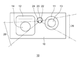
- FIG. 1 is a front view schematically showing the cleaner device 10 according to the embodiment.
- the cleaner device 10 shown in FIG. 1 is a vehicle cleaner device mounted on a vehicle such as an automobile in this embodiment.
- the cleaner device 10 is configured to clean a plurality of objects to be cleaned, for example, the first camera 11 and the second camera 12.
- the first camera 11 and the second camera 12 are arranged side by side and adjacent to each other, for example, as shown in the figure.
- the first camera 11 and the second camera 12 are installed in different postures so as to capture different directions, for example, in front of and behind the vehicle.
- the first camera 11 and the second camera 12 have different outer shapes
- the first camera 11 has a circular shape
- the second camera 12 has a rectangular shape. Has.
- the first camera 11 has a first convex curved surface 13
- the second camera 12 has a second convex curved surface 14.
- These convex curved surfaces are the surfaces of optical elements exposed to the outside, which are components of the camera.
- the optical element may be, for example, a lens, or may be a translucent lens cover for protecting the lens, or may be another optical element.
- the first convex curved surface 13 and the second convex curved surface 14 can also have different shapes according to the design and specifications of each camera.
- the convex curved surface is, for example, a part of a spherical surface.
- the convex curved surface may be another quadric surface such as a paraboloid, or a curved surface having another shape that is convexly curved toward the outside, such as an aspherical surface.
- the convex curved surface is not limited to a curved surface on the entire surface thereof, and may have a shape that looks convex outward as a whole, and may include a flat region as a part thereof.
- the cleaner device 10 includes a nozzle 20, and the nozzle 20 is provided with a plurality of injection ports for injecting cleaning liquids in different directions, for example, a first injection port 22 and a second injection port 24. These plurality of injection ports are arranged so as to inject the cleaning liquid onto the corresponding convex curved surface among the plurality of convex curved surfaces arranged around the nozzle 20. Specifically, the first injection port 22 is arranged so as to inject the cleaning liquid onto the first convex curved surface 13, and the second injection port 24 is arranged so as to inject the cleaning liquid onto the second convex curved surface 14. ing.
- the nozzle 20 is outside the field of view of these cameras, for example, the first camera 11 and the second camera, so as not to interfere with the shooting by the first camera 11 and the second camera 12, or to minimize the influence on the shooting. It is arranged on the side of twelve.
- the first injection port 22 is arranged outside the first convex curved surface 13
- the second injection port 24 is arranged outside the second convex curved surface 14.
- the nozzle 20 is installed between the first camera 11 and the second camera 12.
- the first camera 11 is on the right side of the nozzle 20 and the second camera 12 is on the left side of the nozzle 20.
- the first convex curved surface 13 is located on one side with respect to the nozzle 20, and the second convex curved surface 14 is located on the other side with respect to the nozzle 20. Therefore, the first injection port 22 and the second injection port 24 are provided on the nozzle 20 so as to inject the cleaning liquid in substantially opposite directions to each other.
- the tip of the nozzle 20 has a conical shape, and the first injection port 22 and the second injection port 24 are open on the conical side surface thereof.
- the first injection port 22 and the second injection port 24 are provided on one side and the other side with respect to the center of the nozzle 20.
- the first injection port 22 is configured to inject the cleaning liquid into the first convex curved surface 13 in a fan shape
- the second injection port 24 is configured to inject the cleaning liquid into the second convex curved surface 14 in a fan shape.
- FIG. 1 shows a fan-shaped cleaning liquid layer 26 sprayed from the first injection port 22 to the first convex curved surface 13 and a second convex curved surface 14 from the second injection port 24.
- a layer 28 of a fan-shaped cleaning liquid sprayed on the surface is shown.
- the layer of the fan-shaped cleaning liquid to be sprayed is curved convexly in the same direction as the convex curved surface. It may be determined to have a shaped shape.
- the shape of the second injection port 24 is determined so that the fan-shaped cleaning liquid layer 28 to be ejected has a shape that is convexly curved toward the same direction as the second convex curved surface 14. Has been done.
- the periphery of the first camera 11, the second camera 12, and the nozzle 20 is covered with the cover member 16. Therefore, the portion of the cleaner device 10 other than the nozzle 20 is covered with the cover member 16.
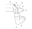
- FIG. 2 is a perspective view schematically showing an attached state of the nozzle assembly 30 of the cleaner device 10 shown in FIG. Note that FIG. 2 shows a state in which the cover member 16 shown in FIG. 1 is removed. Therefore, FIG. 2 shows the nozzle assembly 30 as seen from the second injection port 24 side of the nozzle 20, together with a part of the bracket 18 arranged behind the cover member 16.
- the nozzle assembly 30 includes a nozzle 20 and a nozzle holder 32.
- the nozzle 20 is attached to the nozzle holder 32.
- the nozzle 20 and the nozzle holder 32 are formed of an appropriate synthetic resin material such as a polyacetal resin, an acrylic resin, or a polycarbonate resin.
- the nozzle holder 32 is fixed to the bracket 18 with, for example, a screw 34.
- the nozzle holder 32 may be fixed to the bracket 18 by other fixing means.
- the nozzle assembly 30 is supported by the vehicle body via the bracket 18.
- the bracket 18 may be equipped with not only the nozzle assembly 30 but also the first camera 11 and the second camera 12.
- connection hose 36 is connected to the nozzle holder 32.
- the connection hose 36 is connected to the flow path of the cleaning liquid in the nozzle holder 32, and further, the flow path in the nozzle holder 32 is connected to the first injection port 22 and the second injection port 24 through the internal flow path of the nozzle 20.
- the connection hose 36 is connected to a cleaning liquid supply source including a cleaning liquid tank, a pump for delivering the cleaning liquid from the tank, and the like.
- the cleaning liquid is injected from the cleaning liquid supply source through the internal flow paths of the connecting hose 36, the nozzle holder 32, and the nozzle 20 from the first injection port 22 and the second injection port 24.
- a fan-shaped cleaning liquid layer 26 is sprayed onto the first convex curved surface 13 from the first injection port 22, and a fan-shaped cleaning liquid layer 28 is sprayed from the second injection port 24 to the fan-shaped cleaning liquid layer 28. It is sprayed on the biconvex curved surface 14.
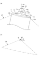
- FIG. 3A and 3B schematically show a fan-shaped cleaning liquid layer 26 jetted from the first injection port 22 of the nozzle 20 and the first convex curved surface 13 of the first camera 11. It is a perspective view which shows.
- FIG. 3A shows the first convex surface of the first injection port 22 when viewed from the direction in which the first convex curved surface 13 of the first camera 11 comes to the front with respect to the first injection port 22 of the nozzle 20.
- FIG. 3B shows the shape of the cleaning liquid layer 26 when the nozzle 20 is viewed from a viewpoint farther from the same direction as in FIG. 3A. show.
- the central axis 21 of the nozzle 20 is shown as the vertical direction for convenience.
- the first camera 11 is installed slightly tilted with respect to the central axis 21 of the nozzle 20, and the first convex curved surface 13 is also slightly tilted with respect to the plane perpendicular to the central axis 21. As shown in the figure, the first convex curved surface 13 is gently inclined downward to the right.
- the first convex curved surface 13 has a center 13a and a peripheral edge 13b. As described above, the first convex curved surface 13 is curved outward (upward in FIG. 3A), so that the center 13a projects outward (upper side) with respect to the peripheral edge 13b. ing.
- the center 13a corresponds to the apex of the first convex curved surface 13 that projects most outward, and the peripheral edge 13b draws a circle centered on the center 13a.
- the first convex curved surface 13 is a gently curved surface, and the height of the center 13a with respect to the peripheral edge 13b is smaller than the radius of the peripheral edge 13b.
- the first injection port 22 has a linear upper edge 22a, lower edge 22b, left edge 22c, and right edge 22d, and has a quadrangular shape with rounded corners as a whole.
- the upper edge 22a and the lower edge 22b are connected to each other by the left edge 22c and the right edge 22d.
- the upper edge 22a and the lower edge 22b are slightly longer than the left edge 22c and the right edge 22d, and the first injection port 22 is elongated laterally.
- the first injection port 22 has a similarly inclined shape. Have. Therefore, the upper edge 22a and the lower edge 22b are gently inclined downward to the right as in the first convex curved surface 13. Since the upper edge 22a and the lower edge 22b of the first injection port 22 extend substantially parallel to each other, the fan-shaped cleaning liquid layer 26 from the first injection port 22 is as shown in FIG. 3 (b). Form a planar liquid layer.
- the first injection port 22 is arranged on the side of the first convex curved surface 13 (rear in FIG. 3A), and is located slightly above the first convex curved surface 13.
- the upper edge 22a and the lower edge 22b of the first injection port 22 are located above the center 13a of the first convex curved surface 13. Therefore, the layer 26 of the cleaning liquid is sprayed diagonally downward from the first injection port 22 toward the first convex curved surface 13.
- the fan-shaped cleaning liquid layer 26 to be sprayed has a first convex shape on one side (back side in FIG. 3A) with respect to the center 13a of the first convex curved surface 13. It corresponds to the curved surface 13 and is arranged so as to flow along the first convex curved surface 13 beyond the center 13a of the first convex curved surface 13 to the other side (front side in FIG. 3A). In this way, the cleaning liquid can be flowed over a relatively wide range of the first convex curved surface 13 (for example, almost the entire area of the first convex curved surface 13), which leads to good cleaning of the first convex curved surface 13.
- the distance between the left edge 22c and the right edge 22d of the first injection port 22 gradually widens from the back to the front of the first injection port 22. Due to such lateral expansion of the first injection port 22, the layer 26 of the cleaning liquid ejected from the first injection port 22 expands in a fan shape in the lateral direction.
- the first injection port 22 is configured such that both ends 26b of the fan-shaped cleaning liquid layer 26 to be sprayed are directed toward the peripheral edge 13b of the first convex curved surface 13, respectively. As shown in FIG. 3A, both ends 26b of the fan-shaped cleaning liquid layer 26 ejected from the first injection port 22 are first convex like tangents from the left edge 22c and the right edge 22d, respectively.
- the first convex curved surface 13 is sprayed so as to pass through the peripheral edge 13b of the curved surface 13. Therefore, it is possible to reduce the amount of cleaning liquid scattered outward from the peripheral edge 13b of the first convex curved surface 13.
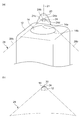
- FIG. 4A shows the second convex surface of the second injection port 24 when viewed from the direction in which the second convex curved surface 14 of the second camera 12 comes to the front with respect to the second injection port 24 of the nozzle 20.
- FIG. 4B shows the shape of the cleaning liquid layer 28 when the nozzle 20 is viewed from a viewpoint farther from the same direction as in FIG. 4A. show.
- the central axis 21 of the nozzle 20 is shown as the vertical direction for convenience.
- the second camera 12 is installed along the central axis 21 of the nozzle 20, and the second convex curved surface 14 is arranged along a plane perpendicular to the central axis 21.
- the second convex curved surface 14 has a center 14a and a peripheral edge 14b.
- the second convex curved surface 14 is curved outward (upward in FIG. 4A), so that the center 14a projects outward (upper side) with respect to the peripheral edge 14b.
- the center 14a corresponds to the apex of the second convex curved surface 14 that projects most outward
- the peripheral edge 14b draws a circle centered on the center 14a.
- the second convex curved surface 14 is a gently curved surface, and the height of the center 14a with respect to the peripheral edge 14b is smaller than the radius of the peripheral edge 14b.
- the shape of the second injection port 24 is defined so that the fan-shaped cleaning liquid layer 28 to be sprayed has a shape that is convexly curved toward the same direction as the second convex curved surface 14. Therefore, the upper edge 24a and the lower edge 24b of the second injection port 24 are curved convexly toward the tip of the nozzle 20. By doing so, as shown in FIG. 4B, the fan-shaped cleaning liquid layer 28 to be sprayed can be easily given a convexly curved shape.
- the second injection port 24 has a linear left edge 24c and right edge 24d, and the upper edge 24a and the lower edge 24b are connected to each other by the left edge 24c and the right edge 24d.
- the upper edge 24a and the lower edge 24b are slightly longer than the left edge 24c and the right edge 24d, and the second injection port 24 is elongated laterally.
- the second injection port 24 is arranged on the side of the second convex curved surface 14 (rear in FIG. 4A), and is located slightly above the second convex curved surface 14.
- the upper edge 24a and the lower edge 24b of the second injection port 24 are located above the center 14a of the second convex curved surface 14. Therefore, the layer 28 of the cleaning liquid is sprayed diagonally downward from the second injection port 24 toward the second convex curved surface 14.
- the fan-shaped cleaning liquid layer 28 to be sprayed has a second convex shape on one side (back side in FIG. 4A) with respect to the center 14a of the second convex curved surface 14. It corresponds to the curved surface 14 and is arranged so as to flow along the second convex curved surface 14 beyond the center 14a of the second convex curved surface 14 to the other side (front side in FIG. 4A). In this way, the cleaning liquid can be flowed over a relatively wide range of the second convex curved surface 14 (for example, almost the entire area of the second convex curved surface 14), which leads to good cleaning of the second convex curved surface 14.
- the distance between the left edge 24c and the right edge 24d of the second injection port 24 gradually widens from the back to the front of the second injection port 24. Due to such lateral expansion of the second injection port 24, the layer 28 of the cleaning liquid ejected from the second injection port 24 expands in a fan shape in the lateral direction.
- the second injection port 24 is configured such that both ends 28b of the fan-shaped cleaning liquid layer 28 to be sprayed are directed toward the peripheral edge 14b of the second convex curved surface 14, respectively.
- both ends 28b of the fan-shaped cleaning liquid layer 28 ejected from the second injection port 24 have a second convex shape like a tangent line from each of the left edge 24c and the right edge 24d.
- the second convex curved surface 14 is sprayed so as to pass through the peripheral edge 14b of the curved surface 14. Therefore, it is possible to reduce the amount of cleaning liquid scattered outward from the peripheral edge 14b of the second convex curved surface 14.
- the nozzle 20 of the cleaner device 10 is arranged outside the second convex curved surface 14, and the second injection port for injecting the cleaning liquid onto the second convex curved surface 14 in a fan shape. 24 is provided.
- the shape of the second injection port 24 is defined so that the fan-shaped cleaning liquid layer 28 to be sprayed has a shape that is convexly curved in the same direction as the second convex curved surface 14.
- the sprayed fan-shaped layer 28 of the cleaning liquid is adapted to the second convex curved surface 14 of the second camera 12, whereby more cleaning liquid can be sprayed on the second convex curved surface 14.
- the cleaning liquid when the cleaning liquid is sprayed linearly from the injection port, it hits the convex curved surface locally, but by spraying the cleaning liquid in a fan shape, it is easy to spray the cleaning liquid over the entire convex curved surface. be.
- the fan-shaped cleaning liquid layer 28 is planar, only the central portion of the liquid layer directly hits the vicinity of the center 14a of the second convex curved surface 14, and the end portion of the liquid layer is the first.
- the liquid may tend to scatter around the second convex curved surface 14 by passing above the peripheral edge 14b without hitting the second convex curved surface 14.
- the fan-shaped cleaning liquid layer 28 is actually curved convexly like the second convex curved surface 14, the entire layer 28 of the cleaning liquid is formed on the second convex curved surface 14. Can be hit directly, and the scattering of such cleaning liquid can be reduced.
- the curved shapes of the upper edge 24a and the lower edge 24b of the second injection port 24 can be directly confirmed visually.
- the upper edge 24a and the lower edge 24b of the second injection port 24 may be magnified by a magnifying glass.
- the curved shape may be visible when viewed.
- FIG. 5 is a front view schematically showing the cleaner device 10 according to another embodiment.
- the cleaner device 10 shown in FIG. 5 is different from the cleaner device 10 shown in FIG. 1 in terms of nozzle configuration, but is common in other respects.
- the cleaner device 10 includes a nozzle assembly 40, and the nozzle assembly 40 is provided with a first nozzle portion 42 having a first injection port 22 and a second nozzle portion 44 having a second injection port 24.
- the first nozzle portion 42 is fixed to a support member such as a bracket with screws 46.
- the first nozzle portion 42 may be fixed to the support member by other fixing means.
- the second nozzle portion 44 is connected to the first nozzle portion 42.
- the cleaning liquid is supplied to the first nozzle unit 42 from a supply source such as a tank, and is supplied to the second nozzle unit 44 via the first nozzle unit 42.
- the cleaning liquid supplied to the first nozzle unit 42 is ejected from the first injection port 22, and the cleaning liquid supplied to the second nozzle unit 44 is injected from the second injection port 24.
- the first injection port 22 is arranged so as to inject the cleaning liquid onto the first convex curved surface 13 of the first camera 11, and the second injection port 24 injects the cleaning liquid onto the second convex curved surface 14 of the second camera 12. Arranged to do.
- the first nozzle portion 42 is arranged above the first camera 11, and the first injection port 22 injects the cleaning liquid downward toward the first convex curved surface 13.
- the second nozzle portion 44 is arranged between the first camera 11 and the second camera 12, and the second injection port 24 injects the cleaning liquid diagonally downward toward the second convex curved surface 14.
- the first injection port 22 is configured to inject the cleaning liquid into the first convex curved surface 13 in a fan shape
- the second injection port 24 is configured to inject the cleaning liquid into the second convex curved surface 14 in a fan shape.
- FIG. 5 shows a fan-shaped cleaning liquid layer 26 sprayed from the first injection port 22 to the first convex curved surface 13 and a second convex curved surface 14 from the second injection port 24.
- a layer 28 of a fan-shaped cleaning liquid sprayed on the surface is shown.
- the shape of one or both of the first injection port 22 and the second injection port 24 is such that the layer of the fan-shaped cleaning liquid to be sprayed is a convex curved surface. It may be defined to have a shape curved convexly in the same direction as the above.
- the shape of the second injection port 24 is determined so that the fan-shaped cleaning liquid layer 28 to be ejected has a shape that is convexly curved toward the same direction as the second convex curved surface 14. Has been done.
- the shape of the second injection port 24 can be the same as that described with reference to FIGS. 4 (a) and 4 (b).
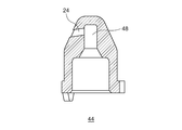
- FIG. 6 is a diagram schematically showing an AA line cross section of the second nozzle portion 44 shown in FIG.
- the second nozzle portion 44 is formed with an internal flow path 48 whose diameter decreases toward the tip of the nozzle.
- the second injection port 24 is provided so as to be bent at a substantially right angle from the small diameter portion on the tip end side of the internal flow path 48.
- the cleaning liquid is applied to the second convex curved surface 14. It is slightly diagonally downward to point.
- the second nozzle portion 44 of the cleaner device 10 is arranged outside the second convex curved surface 14, and the cleaning liquid is sprayed onto the second convex curved surface 14 in a fan shape.
- the injection port 24 is provided.
- the shape of the second injection port 24 is defined so that the fan-shaped cleaning liquid layer 28 to be sprayed has a shape that is convexly curved in the same direction as the second convex curved surface 14.
- the sprayed fan-shaped layer 28 of the cleaning liquid is adapted to the second convex curved surface 14 of the second camera 12, whereby more cleaning liquid can be sprayed on the second convex curved surface 14.
- FIG. 7 is a front view schematically showing the cleaner device 110 according to the embodiment.
- the cleaner device 110 shown in FIG. 7 is a vehicle cleaner device mounted on a vehicle such as an automobile in this embodiment.
- the cleaner device 110 is configured to clean a plurality of objects to be cleaned, for example, the first camera 111 and the second camera 112.
- the first camera 111 and the second camera 112 are arranged side by side and adjacent to each other, for example, as shown in the figure.
- the first camera 111 and the second camera 112 are installed in different postures so as to capture different directions, for example, in front of and behind the vehicle.
- the first camera 111 and the second camera 112 have different outer shapes
- the first camera 111 has a circular shape
- the second camera 112 has a rectangular shape. Has.
- the first camera 111 has a first surface 113 and the second camera 112 has a second surface 114.
- These surfaces to be cleaned are the surfaces of optical elements exposed to the outside, which are components of the camera.
- the optical element may be, for example, a lens, or may be a translucent lens cover for protecting the lens, or may be another optical element.
- the first surface 113 and the second surface 114 may be curved surfaces that are convexly curved toward the outside, such as a spherical surface, or may be a flat surface or other surface having a shape.
- the first surface 113 and the second surface 114 may have the same shape, but in general, they may have different shapes depending on the design and specifications of each camera.
- the cleaner device 110 includes a nozzle assembly 120, and the nozzle assembly 120 is provided with a first nozzle portion 121 having a first injection port 122 and a second nozzle portion 123 having a second injection port 124.
- the nozzle assembly 120 has a substantially L-shaped shape in which a horizontally long first nozzle portion 121 and a vertically long second nozzle portion 123 are connected to each other.
- the cleaning liquid is supplied to the first nozzle unit 121 from a supply source such as a tank, and is supplied to the second nozzle unit 123 via the first nozzle unit 121.
- the cleaning liquid supplied to the first nozzle unit 121 is ejected from the first injection port 122, and the cleaning liquid supplied to the second nozzle unit 123 is injected from the second injection port 124.
- the first injection port 122 is arranged so as to inject the cleaning liquid onto the first surface 113
- the second injection port 124 is arranged so as to inject the cleaning liquid onto the second surface 114.
- the first injection port 122 is configured to inject the cleaning liquid into the first surface 113 in a fan shape
- the second injection port 124 is configured to inject the cleaning liquid into the second surface 114 in a fan shape.
- FIG. 7 shows a fan-shaped cleaning liquid layer 126 sprayed from the first injection port 122 onto the first surface 113 and sprayed from the second injection port 124 onto the second surface 114.
- a fan-shaped cleaning liquid layer 128 is shown.
- the nozzle assembly 120 is arranged outside the field of view of the first camera 111 and the second camera 112 so as not to interfere with the shooting or to minimize the influence on the shooting.
- the first nozzle portion 121 is arranged above the first camera 111, and the first injection port 122 injects the cleaning liquid downward toward the first surface 113.
- the second nozzle portion 123 is arranged between the first camera 111 and the second camera 112, and the second injection port 124 injects the cleaning liquid diagonally downward toward the second surface 114.
- the periphery of the first camera 111, the second camera 112, and the nozzle assembly 120 is covered with the cover member 116.
- a support member for supporting the first camera 111, the second camera 112, and the nozzle assembly 120 for example, the bracket 118 shown in FIG. 8A, is provided.
- a first camera 111, a second camera 112, and a nozzle assembly 120 are attached to the bracket 118.
- the cleaner device 110 is a vehicle cleaner device
- the first camera 111, the second camera 112, and the nozzle assembly 120 are supported by the vehicle body via the bracket 118.
- the first nozzle portion 121 not only has a role of spraying a cleaning liquid on the first surface 113 of the first camera 111, but is also provided as a fixing portion for fixing the nozzle assembly 120 to the bracket 118.
- the first nozzle portion 121 is fixed to the bracket 118 by, for example, a screw 30 as a fixing member.
- the first nozzle portion 121 may be fixed to the bracket 118 or the support member by other fixing means.
- Each part of the nozzle assembly 120 and the bracket 118 are made of an appropriate synthetic resin material such as polyacetal resin, acrylic resin, and polycarbonate resin.
- Each part of the nozzle assembly 120 and the bracket 118 are made of, for example, the same material, but may be made of different materials.
- the nozzle assembly 120 is combined with the bracket 118 to form a nozzle assembly for the object to be cleaned (that is, the first camera 111 and the second camera 112). It is configured to regulate the displacement of 120.
- the first nozzle portion 121 is fixed to the bracket 118
- the second nozzle portion 123 is connected to the first nozzle portion 121
- the displacement regulating structure of the nozzle assembly 120 is formed by the second nozzle portion 123 and the bracket 118. ..
- the second nozzle portion 123 and the bracket 118 are not directly fixed, but the second nozzle portion 123 and the bracket 118 are provided with a concave-convex shape that is combined with each other so as to suppress the movement of the nozzle assembly 120 with respect to the bracket 118 as a displacement control structure. There is.
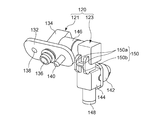
- FIG. 8 (a) is a perspective view schematically showing a state in which the nozzle assembly 120 of the cleaner device 110 shown in FIG. 7 is attached to the bracket 118
- FIG. 8 (b) is a perspective view in FIG. 8 (a). It is a partial cross-sectional view which cut out a part of the 2nd nozzle part 123 of a nozzle assembly 120. Note that in FIGS. 8A and 8B, the nozzle assembly 120 viewed from the second injection port 124 side of the second nozzle portion 123 with the cover member 116 shown in FIG. 7 removed is the bracket 118. Shown with some of. FIG. 8B shows a vertical cross section of the second nozzle portion 123.
- FIG. 9 is a perspective view showing the bracket 118 shown in FIG. 8A in a state where the nozzle assembly 120 is not attached.
- FIG. 10 is a perspective view schematically showing the nozzle assembly 120 shown in FIG. 8A from the back side.
- 11 (a) shows the FF cross section shown in FIG. 8 (a)
- FIG. 11 (b) shows the GG cross section shown in FIG. 11 (a).
- the first nozzle portion 121 is formed in a horizontally long substrate portion 132, an injection portion 134 formed in the front center portion of the substrate portion 132, and a back center portion of the substrate portion 132. It has an entrance portion 136.
- the injection unit 134 is provided with the first injection port 122 shown in FIG. 7.
- An internal flow path for guiding the cleaning liquid to the first injection port 122 and the second nozzle portion 123 is formed through the substrate portion 132 from the inlet portion 136 to the injection portion 134.
- a screw hole 138 is formed on one side of the injection portion 134, and a positioning pin 140 is formed on the opposite side of the injection portion 134.
- the screw hole 138 penetrates from the front surface to the back surface of the substrate portion 132.
- the positioning pin 140 is a rod-shaped protrusion protruding from the back surface of the substrate portion 132.
- the second nozzle unit 123 has a nozzle 142 having a second injection port 124 and a vertically long nozzle holder 144.
- the nozzle holder 144 has a connecting portion 146 for connecting the second nozzle portion 123 to the first nozzle portion 121, and a nozzle holding portion 147 shown in FIG. 11B.
- the connection portion 146 is formed on, for example, the upper part of the side surface of the nozzle holder 144, and is fitted into the injection portion 134 of the first nozzle portion 121 by, for example, press fitting, whereby the second nozzle portion 123 is coupled to the first nozzle portion 121. ..
- the nozzle holding portion 147 is formed in, for example, the central portion of the front surface of the nozzle holder 144.
- the nozzle 142 is fitted into the nozzle holding portion 147 by, for example, press fitting, whereby the nozzle 142 is mounted on the nozzle holder 144.
- the nozzle holder 144 is formed with an internal flow path for guiding the cleaning liquid from the connecting portion 146 to the nozzle holding portion 147. Therefore, the cleaning liquid can be flowed from the injection unit 134 of the first nozzle unit 121 to the second injection port 124 of the nozzle 142 through the internal flow path of the nozzle holder 144.
- a cap 148 is attached to the lower end of the nozzle holder 144 so that the cleaning liquid flowing through the internal flow path of the nozzle holder 144 does not flow out from the opening at the lower end of the nozzle holder 144, and this opening is closed by the cap 148. ..
- the nozzle holder 144 has a convex portion 150 as the above-mentioned displacement restricting structure, and the convex portion 150 is formed in, for example, the central portion of the back surface of the nozzle holder 144.
- the convex portion 150 has an H-shaped shape, and the two first vertical ribs 150a and the lateral portions connecting the first vertical ribs 150a at the central portion thereof. It has a rib 150b.
- the bracket 118 has a mounting portion 152 overhanging toward the front side.
- the mounting portion 152 has a mounting surface 153 that comes into contact with the back surface of the substrate portion 132 of the first nozzle portion 121 when the first nozzle portion 121 is mounted.
- a flow path 154 is opened in the central portion of the mounting surface 153, a screw hole 156 is formed on one side of the flow path 154, and a positioning hole 158 is formed on the opposite side of the injection portion 134.
- the flow path 154 is connected to a cleaning liquid supply source (not shown) including a cleaning liquid tank, a pump for delivering the cleaning liquid from the tank, and the like.
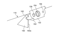
- the bracket 118 has a second vertical rib 160 protruding toward the front side.
- the second vertical rib 160 is formed at a position corresponding to the back of the second nozzle portion 123 when the nozzle assembly 120 is attached to the bracket 118.
- the second vertical rib 160 is provided with a recess 162 as the displacement restricting structure described above.
- the recess 162 is formed on the front end surface 160a of the second vertical rib 160 so as to regulate the displacement of the second nozzle portion 123 in at least one direction by combining with the convex portion 150 of the nozzle holder 144.
- the nozzle assembly 120 is fixed to the bracket 118 by fixing the first nozzle portion 121 to the mounting portion 152 of the bracket 118.
- the positioning pin 140 of the first nozzle portion 121 is inserted into the positioning hole 158 of the bracket 118, and the inlet portion 136 of the first nozzle portion 121 is fitted into the flow path 154 of the bracket 118.
- a screw 30 (see FIG. 7) is screwed into the screw hole 138 of the first nozzle portion 121 and the screw hole 156 of the bracket 118, and the first nozzle portion 121 is fixed to the mounting portion 152 of the bracket 118.
- the nozzle assembly 120 is fixed to the bracket 118 with one screw 30, the assembling work is relatively easy.
- the convex portion 150 of the second nozzle portion 123 is the concave portion 162 of the bracket 118 as shown in FIGS. 8 (b), 11 (a) and 11 (b). Enters. In this way, the convex portion 150 and the concave portion 162 are combined. Since the recess 162 is a notch formed in the second vertical rib 160, the convex portion 150 is vertically sandwiched by the second vertical rib 160 in the recess 162. At this time, there may be a slight gap between the convex portion 150 and the concave portion 162, or the convex portion 150 and the concave portion 162 may be in contact with each other at least a part of their surfaces.
- the convex portion 150 of the second nozzle portion 123 abuts on the second vertical rib 160 in the concave portion 162, whereby the bracket.
- the vertical displacement or movement of the second nozzle unit 123 with respect to 118 is restricted.
- the convex portion 150 of the nozzle assembly 120 and the concave portion 162 of the bracket 118 are not fixed to each other. By doing so, since it is only necessary to combine the convex portion 150 and the concave portion 162 without fixing them to each other, the assembling work becomes easy.
- the front end surface 160a of the second vertical rib 160 provided with the recess 162 faces the back surface of the second nozzle portion 123 on the lower side of the recess 162. There may be a slight gap between the front end surface 160a of the second vertical rib 160 and the back surface of the second nozzle portion 123, or they may be in contact with each other.
- the nozzle assembly 120 eg, the second nozzle portion 123
- the second nozzle portion 123 abuts on the front end surface 160a of the second vertical rib 160, whereby the second nozzle with respect to the bracket 118.
- the displacement or movement of the portion 123 in the front-rear direction is restricted.
- the two first vertical ribs 150a of the convex portion 150 are arranged apart from each other on both sides of the second vertical rib 160 of the bracket 118, and the two first vertical ribs 150a are each the first. 2 Not in contact with the vertical rib 160. Therefore, the displacement of the second nozzle portion 123 with respect to the bracket 118 in the left-right direction is allowed. However, instead of this, the second nozzle portion 123 with respect to the bracket 118 is brought into contact with or sufficiently close to the convex portion 150 and the concave portion 162 so as to sandwich the second vertical rib 160 between the two first vertical ribs 150a. Left-right displacement or movement of the may be restricted.
- the flow path 154 of the bracket 118 is connected to the first injection port 122 through the internal flow path of the first nozzle portion 121.
- the flow path 154 is connected to the second injection port 124 through the internal flow path of the first nozzle portion 121 and the second nozzle portion 123. Therefore, when the cleaner device 110 is operated, the cleaning liquid is ejected from the cleaning liquid supply source through the flow path 154, the first nozzle portion 121, and the second nozzle portion 123 from the first injection port 122 and the second injection port 124 (FIG. 8).
- the flow of the cleaning liquid is schematically shown by an arrow).
- a fan-shaped cleaning liquid layer 126 is sprayed from the first injection port 122 onto the first surface 113 of the first camera 111, and a fan-shaped cleaning liquid layer 128 is sprayed from the second injection port 124 onto the second surface 114 of the second camera 112. Is sprayed on.
- the cleaner device 110 can clean the first camera 111 and the second camera 112 with a cleaning liquid, as shown in FIG.
- an external force may be applied to the nozzle assembly 120, such as a worker's hand accidentally hitting the nozzle assembly 120. If such an accidental external force is large, unintended movement or misalignment may occur in the nozzle assembly 120.
- the portion of the nozzle assembly 120 on which such an accidental external force acts is relatively far from the fixing portion of the nozzle assembly 120 to the bracket 118, that is, the first nozzle portion 121, for example, the second nozzle portion 123.
- the torque applied by this external force may increase, resulting in unintended movement or misalignment in the nozzle assembly 120.
- first injection port 122 or the second injection port 124 may be displaced from the correct position. If the direction of injection of the cleaning liquid from the nozzle is changed due to the misalignment of the injection port, it may be difficult for the cleaning fluid to hit the first camera 111 or the second camera 112, and cleaning may not be successful.
- the nozzle assembly 120 of the cleaner device 110 has a fixing portion, that is, a first nozzle portion 121, which is fixed to the bracket 118 at a portion different from the recess 162 of the bracket 118, and a recess of the bracket 118. It comprises a protrusion 150 that, when combined with 162, regulates the displacement of the nozzle assembly 120 with respect to the first camera 111 and the second camera 112.
- the convex portion 150 is formed on the second nozzle portion 123.
- the nozzle assembly is not only secured to the bracket 118 to which the first camera 111 and the second camera 112 are attached, but is also combined with the recess 162 and the protrusion 150 of the bracket 118, thereby the first.
- the displacement of the nozzle assembly 120 with respect to the camera 111 and the second camera 112 is restricted. Therefore, the misalignment of the first injection port 122 and the second injection port 124 due to an accidental external force is prevented or sufficiently suppressed.
- the first injection port 122 and the second injection port 124 can be held in the correct positions.
- the cleaner device 170 is common to the cleaner device 110 shown in FIG. 7 in that it is provided for cleaning the first camera 111 and the second camera 112, but differs in terms of nozzle configuration and displacement control structure.
- FIG. 12 is a front view schematically showing the cleaner device 170 according to another embodiment.
- 13 (a) is a perspective view schematically showing a state in which the nozzle assembly 171 of the cleaner device 170 shown in FIG. 12 is attached to the bracket 175, and
- FIG. 13 (b) is a perspective view in FIG. 13 (a). It is a partial cross-sectional view which cut out a part of the nozzle assembly 171. Note that FIGS. 13 (a) and 13 (b) show the nozzle assembly 171 together with a part of the bracket 175 with the cover member 174 shown in FIG. 12 removed.
- FIG. 14 is a perspective view showing the bracket 175 shown in FIG. 13A in a state where the nozzle assembly 171 is not attached.
- FIG. 15 is a perspective view schematically showing the nozzle assembly 171 shown in FIG. 13A from the back side.
- FIG. 16 shows a cross section taken along the line AA shown in FIG. 13 (a).
- the cleaner device 110 includes a nozzle 172, and the nozzle 172 is provided with a plurality of injection ports for injecting cleaning liquids in different directions, for example, a first injection port 122 and a second injection port 124.
- the first injection port 122 is arranged so as to inject the cleaning liquid onto the first surface 113 of the first camera 111
- the second injection port 124 is arranged so as to inject the cleaning liquid onto the second surface 114 of the second camera 112. Has been done.
- the nozzle 172 is installed between the first camera 111 and the second camera 112. As shown in FIG. 12, the first camera 111 is to the right of the nozzle 172 and the second camera 112 is to the left of the nozzle 172. Therefore, the first injection port 122 and the second injection port 124 are provided on the nozzle 172 so as to inject the cleaning liquid in substantially opposite directions to each other.
- the tip of the nozzle 172 has a conical shape, and the first injection port 122 and the second injection port 124 are opened on the conical side surface thereof.
- the first injection port 122 and the second injection port 124 are provided on one side and the other side with respect to the center of the nozzle 172.
- the first injection port 122 is configured to inject the cleaning liquid into the first surface 113 in a fan shape
- the second injection port 124 is configured to inject the cleaning liquid into the second surface 114 in a fan shape.
- FIG. 12 shows a fan-shaped cleaning liquid layer 126 sprayed from the first injection port 122 to the first surface 113 and sprayed from the second injection port 124 to the second surface 114.
- a fan-shaped cleaning liquid layer 128 is shown.
- the periphery of the first camera 111, the second camera 112, and the nozzle 172 is covered with the cover member 174.
- a support member for supporting the first camera 111, the second camera 112, and the nozzle assembly 171 is provided, for example, the bracket 175 shown in FIG. 13 (a).
- a first camera 111, a second camera 112, and a nozzle assembly 171 are attached to the bracket 175.
- the cleaner device 110 is a vehicle cleaner device
- the first camera 111, the second camera 112, and the nozzle assembly 171 are supported by the vehicle body via the bracket 175.
- the nozzle assembly 171 includes a nozzle 172 and a nozzle holder 173.
- the nozzle 172 is mounted on the front surface of the nozzle holder 173.
- the nozzle 172 and the nozzle holder 173 are formed of an appropriate synthetic resin material such as a polyacetal resin, an acrylic resin, or a polycarbonate resin.
- a connection hose 176 is connected to the lower end of the nozzle holder 173.
- the connection hose 176 is connected to the flow path of the cleaning liquid in the nozzle holder 173, and further, the flow path in the nozzle holder 173 is connected to the first injection port 122 and the second injection port 124 through the internal flow path of the nozzle 172.
- the connection hose 176 is connected to a cleaning liquid supply source including a cleaning liquid tank, a pump for delivering the cleaning liquid from the tank, and the like.
- the cleaning liquid is injected from the cleaning liquid supply source through the internal flow paths of the connecting hose 176, the nozzle holder 173, and the nozzle 172 from the first injection port 122 and the second injection port 124.
- the fan-shaped cleaning liquid layer 126 is sprayed onto the first surface 113 from the first injection port 122, and the fan-shaped cleaning liquid layer 128 is sprayed from the second injection port 124 onto the second surface. It is sprayed on 114.
- the cleaner device 170 can clean the first camera 111 and the second camera 112 with a cleaning liquid.
- the nozzle holder 173 has a fixing portion 177 and a recess 178 as a displacement regulating structure, as shown in FIG. 15, for example.
- the fixing portion 177 is formed at the upper end portion of the nozzle holder 173, and the screw hole 179 penetrates from the front surface to the back surface.
- the recess 178 is formed on the back surface of the nozzle holder 173 on the side opposite to the nozzle 172.
- the bracket 175 has a mounting portion 181 in which a screw hole 180 is formed, and a convex portion 182 as a displacement restricting structure.
- the convex portion 182 is provided so as to project toward the front side with respect to the mounting portion 181.
- the protrusion 182 is configured to regulate displacement of the nozzle assembly 171 in at least one direction by combining with the recess 178 of the nozzle holder 173.
- the bracket 175 is not provided with a flow path for the cleaning liquid.
- a screw 83 as a fixing member is screwed into the screw hole 179 of the fixing portion 177 and the screw hole 180 of the mounting portion 181, and the fixing portion 177 of the nozzle holder 173 is fixed to the mounting portion 181 of the bracket 175.
- the concave portion 178 of the nozzle holder 173 is inserted into the convex portion 182 of the bracket 175, and the convex portion 182 and the concave portion 178 are combined.
- the nozzle assembly 171 is fixed to the bracket 175.
- the nozzle holder 173 When an external force acts on the nozzle assembly 171 in the vertical direction, the nozzle holder 173 abuts on the convex portion 182 of the bracket 175 in the recess 178, thereby restricting the vertical displacement or movement of the nozzle assembly 171 with respect to the bracket 175. Nozzle. Similarly, the lateral and anteroposterior displacement of the nozzle assembly 171 with respect to the bracket 175 is also regulated.
- the convex portion 182 when the convex portion 182 is arranged in the concave portion 178, the convex portion 182 comes into contact with the protrusion 184 formed in the concave portion 178.
- Contact between the protrusion 182 and the protrusion 184 in the recess 178 positions the nozzle assembly 171 with respect to the bracket 175, thereby causing the first injection port 122 and the second injection port 124 to be the first camera 111 and the second, respectively. It can be accurately positioned with respect to the camera 112.
- the nozzle assembly 171 of the cleaner device 170 includes a fixing portion 177 fixed to the bracket 175 at a portion different from the convex portion 182 of the bracket 175, and a convex portion 182 of the bracket 175.
- a recess 178 that, when combined, regulates the displacement of the nozzle assembly 171 with respect to the first camera 111 and the second camera 112.
- the recess 178 is formed in the nozzle holder 173.
- the nozzle assembly 171 is not only fixed to the bracket 175 to which the first camera 111 and the second camera 112 are attached, but is also combined by the convex portions 182 and the concave portions 178 of the bracket 175, whereby the first camera assembly 171 is fixed.
- the displacement of the nozzle assembly 171 with respect to the 1st camera 111 and the 2nd camera 112 is restricted. Therefore, the misalignment of the first injection port 122 and the second injection port 124 due to an accidental external force is prevented or sufficiently suppressed.
- the first injection port 122 and the second injection port 124 can be held in the correct positions.
- the concave portion 178 of the nozzle assembly 171 and the convex portion 182 of the bracket 175 are not fixed to each other. In this way, the convex portion 182 and the concave portion 178 need only be combined without being fixed to each other, so that the assembling work becomes easy.
- the present invention is not limited to the above-described embodiments and modifications, and it is possible to combine embodiments and modifications, and to make further modifications such as various design changes based on the knowledge of those skilled in the art.
- the present invention also includes embodiments and modifications in which such combinations or further modifications are added.
- the above-mentioned embodiments and modifications, and the new embodiments resulting from the combination of the above-mentioned embodiments and modifications and the following modifications combine the effects of the combined embodiments, modifications and further modifications. Have.
- the upper edge 24a and the lower edge 24b of the second injection port 24 are convexly curved in the same direction as the second convex curved surface 14, but the present invention is not limited to this. At least one of the upper edge 24a and the lower edge 24b of the second injection port 24, for example, at least the upper edge 24a may be curved convexly in accordance with the second convex curved surface 14.
- one of the first injection port 22 and the second injection port 24, specifically, the shape of the second injection port 24 is convexly curved in accordance with the second convex curved surface 14.
- both the first injection port 22 and the second injection port 24 may be curved convexly. Therefore, the nozzle is provided with a plurality of injection ports, and each of the plurality of injection ports so as to inject the cleaning fluid into a fan shape on the corresponding convex curved surface among the plurality of convex curved surfaces arranged around the nozzle. It may be arranged.
- the shape of each injection port is defined so that the fan-shaped cleaning fluid layer injected from the injection port has a shape that is convexly curved in the same direction as the convex curved surface corresponding to the injection port. May be good.
- the plurality of injection ports are arranged so as to inject the cleaning liquid onto different objects to be cleaned.
- the plurality of injection ports are arranged to inject the cleaning liquid to different parts of the same object to be cleaned or to the same part of the same object to be cleaned from different directions. good.
- the number of injection ports is not particularly limited. Three or more injection ports may be provided, or only one may be provided.
- the arrangement and shape of the convex and concave portions as the displacement regulation structure are not limited to the above-mentioned specific form, and may take various other forms.
- an H-shaped convex portion 150 having two first vertical ribs 150a and one horizontal rib 150b is used.
- the convex portion 150 may have only the horizontal rib 150b without the first vertical rib 150a.
- the convex portion 150 is formed on the back surface of the nozzle holder 144, but instead of the convex portion 150, for example, a convex portion is formed on the side surface of the nozzle holder 144 (the surface on the same side as the connection portion 146 or the surface on the opposite side). Is formed, and a concave portion to be combined with the convex portion may be formed in the bracket 118.
- a concave portion may be provided instead of the convex portion.
- a convex portion may be provided instead of the concave portion.
- a concave portion is formed in the nozzle assembly 120, a convex portion is formed in the bracket 118, and the concave portion and the convex portion are formed.
- a displacement regulation structure may be formed.
- a convex portion is formed in the nozzle assembly 171 and a concave portion is formed in the bracket 175, and the convex portion and the concave portion are combined.
- the displacement regulation structure may be formed by.
- the nozzle having the injection port and the nozzle holder are prepared as separate parts, and the nozzle is mounted on the nozzle holder.
- one nozzle component in which the nozzle and the nozzle holder are integrally molded may be used.
- the shape of one or both of the first injection port 122 and the second injection port 124 is the same as that of the embodiment described with reference to FIG. May be defined so that the sprayed fan-shaped layer of cleaning liquid has a shape that is convexly curved in the same direction as the convex curved surface of the object to be cleaned.
- the cleaning fluid is a cleaning fluid
- the cleaning fluid may be a gas such as air.
- the vehicle cleaner device for cleaning the in-vehicle camera is described as an example, but the object to be cleaned by the cleaner devices 10 and 110 is an in-vehicle camera such as a distance measuring sensor such as LiDAR. It may be an in-vehicle sensor other than the above, or it may be another in-vehicle device.
- the optical element to be cleaned may form a part of an in-vehicle device to be cleaned.
- the cleaner devices 10 and 110 are not limited to those for vehicles.
- the cleaner device according to the embodiment can be mounted on an outdoor lighting device such as a street light, a sensor device, or various other devices, and for cleaning various objects to be cleaned provided in such a device. May be used for.
- the present invention can be used for a nozzle and a cleaner device including the nozzle.
Abstract
La présente invention concerne une buse (20) d'un appareil de nettoyage (10) qui lave une seconde caméra (12) qui comporte une seconde surface incurvée de projection (14). La buse (20) est disposée à l'extérieur de la seconde surface incurvée de projection (14) et est pourvue d'un second orifice de pulvérisation (24) qui pulvérise un fluide de nettoyage dans une forme en éventail vers la seconde surface incurvée de projection (14). La forme du second orifice de pulvérisation (24) est spécifiée de telle sorte qu'une couche (28) du fluide de nettoyage pulvérisé sous une forme en éventail présente une forme incurvée faisant saillie dans la même direction que celle de la seconde surface incurvée de projection (14).
Priority Applications (4)
| Application Number | Priority Date | Filing Date | Title |
|---|---|---|---|
| CN202180046823.6A CN115803235A (zh) | 2020-06-30 | 2021-06-08 | 喷嘴、喷嘴组件及清洁器装置 |
| EP21833870.5A EP4173901A4 (fr) | 2020-06-30 | 2021-06-08 | Buse, ensemble buse et appareil de nettoyage |
| JP2022533779A JPWO2022004297A1 (fr) | 2020-06-30 | 2021-06-08 | |
| US18/147,121 US20230132583A1 (en) | 2020-06-30 | 2022-12-28 | Nozzle, nozzle assembly, and cleaner device |
Applications Claiming Priority (4)
| Application Number | Priority Date | Filing Date | Title |
|---|---|---|---|
| JP2020112767 | 2020-06-30 | ||
| JP2020-112767 | 2020-06-30 | ||
| JP2020117281 | 2020-07-07 | ||
| JP2020-117281 | 2020-07-07 |
Related Child Applications (1)
| Application Number | Title | Priority Date | Filing Date |
|---|---|---|---|
| US18/147,121 Continuation US20230132583A1 (en) | 2020-06-30 | 2022-12-28 | Nozzle, nozzle assembly, and cleaner device |
Publications (1)
| Publication Number | Publication Date |
|---|---|
| WO2022004297A1 true WO2022004297A1 (fr) | 2022-01-06 |
Family
ID=79315219
Family Applications (1)
| Application Number | Title | Priority Date | Filing Date |
|---|---|---|---|
| PCT/JP2021/021728 WO2022004297A1 (fr) | 2020-06-30 | 2021-06-08 | Buse, ensemble buse et appareil de nettoyage |
Country Status (5)
| Country | Link |
|---|---|
| US (1) | US20230132583A1 (fr) |
| EP (1) | EP4173901A4 (fr) |
| JP (1) | JPWO2022004297A1 (fr) |
| CN (1) | CN115803235A (fr) |
| WO (1) | WO2022004297A1 (fr) |
Families Citing this family (3)
| Publication number | Priority date | Publication date | Assignee | Title |
|---|---|---|---|---|
| US20220009453A1 (en) * | 2020-07-09 | 2022-01-13 | A. Raymond Et Cie | Bracket and modular assembly for fluid spray system |
| US11780409B2 (en) * | 2020-08-06 | 2023-10-10 | Ford Global Technologies, Llc | Sensor apparatus with cleaning |
| US11921208B2 (en) * | 2020-08-27 | 2024-03-05 | Ford Global Technologies, Llc | Sensor apparatus with cleaning |
Citations (9)
| Publication number | Priority date | Publication date | Assignee | Title |
|---|---|---|---|---|
| JPS6359361A (ja) * | 1986-08-29 | 1988-03-15 | Koito Mfg Co Ltd | ヘッドランプクリ−ナ用超広角ノズル |
| US20160272163A1 (en) * | 2015-03-17 | 2016-09-22 | Magna Electronics Inc. | Vehicle camera with lens washer system |
| JP2017520443A (ja) * | 2014-04-16 | 2017-07-27 | ディエルエイチ・ボウルズ・インコーポレイテッドdlhBOWLES Inc. | 複数の画像センサを同時に清掃するための統合的複数画像センサ及びレンズ洗浄ノズルアセンブリ及びその方法 |
| JP2018095255A (ja) * | 2015-06-30 | 2018-06-21 | 株式会社小糸製作所 | 異物除去装置および当該異物除去装置を備える車両 |
| US20180272996A1 (en) * | 2015-05-07 | 2018-09-27 | Jetwipe 2017 Ivs | Wiperless cleaning system for transparent surfaces using air jets |
| WO2018220175A1 (fr) * | 2017-06-02 | 2018-12-06 | Jetwipe 2017 Ivs | Système de nettoyage pour surface optique |
| WO2018230558A1 (fr) | 2017-06-13 | 2018-12-20 | 株式会社小糸製作所 | Système de nettoyage de véhicule et véhicule équipé d'un système de nettoyage de véhicule |
| JP2019526206A (ja) * | 2016-07-28 | 2019-09-12 | ディエルエイチ・ボウルズ・インコーポレイテッドdlhBOWLES Inc. | 自給型カメラ洗浄システム及びその方法 |
| JP2019156260A (ja) * | 2018-03-15 | 2019-09-19 | 株式会社小糸製作所 | 車両用クリーナノズルおよび車両用クリーナノズルの組み付け方法 |
Family Cites Families (3)
| Publication number | Priority date | Publication date | Assignee | Title |
|---|---|---|---|---|
| FR2619066B1 (fr) * | 1987-08-06 | 1989-12-22 | Cibie Projecteurs | Dispositif pour laver la glace d'un projecteur, notamment pour vehicule automobile |
| US7111793B2 (en) * | 2002-08-22 | 2006-09-26 | Asmo Co., Ltd. | Washer nozzle and washer apparatus |
| FR3056526B1 (fr) * | 2016-09-28 | 2018-10-26 | Valeo Systemes D'essuyage | Dispositif de nettoyage destine a projeter au moins un fluide vers une surface a nettoyer d'un vehicule automobile |
-
2021
- 2021-06-08 JP JP2022533779A patent/JPWO2022004297A1/ja active Pending
- 2021-06-08 EP EP21833870.5A patent/EP4173901A4/fr active Pending
- 2021-06-08 CN CN202180046823.6A patent/CN115803235A/zh active Pending
- 2021-06-08 WO PCT/JP2021/021728 patent/WO2022004297A1/fr unknown
-
2022
- 2022-12-28 US US18/147,121 patent/US20230132583A1/en active Pending
Patent Citations (9)
| Publication number | Priority date | Publication date | Assignee | Title |
|---|---|---|---|---|
| JPS6359361A (ja) * | 1986-08-29 | 1988-03-15 | Koito Mfg Co Ltd | ヘッドランプクリ−ナ用超広角ノズル |
| JP2017520443A (ja) * | 2014-04-16 | 2017-07-27 | ディエルエイチ・ボウルズ・インコーポレイテッドdlhBOWLES Inc. | 複数の画像センサを同時に清掃するための統合的複数画像センサ及びレンズ洗浄ノズルアセンブリ及びその方法 |
| US20160272163A1 (en) * | 2015-03-17 | 2016-09-22 | Magna Electronics Inc. | Vehicle camera with lens washer system |
| US20180272996A1 (en) * | 2015-05-07 | 2018-09-27 | Jetwipe 2017 Ivs | Wiperless cleaning system for transparent surfaces using air jets |
| JP2018095255A (ja) * | 2015-06-30 | 2018-06-21 | 株式会社小糸製作所 | 異物除去装置および当該異物除去装置を備える車両 |
| JP2019526206A (ja) * | 2016-07-28 | 2019-09-12 | ディエルエイチ・ボウルズ・インコーポレイテッドdlhBOWLES Inc. | 自給型カメラ洗浄システム及びその方法 |
| WO2018220175A1 (fr) * | 2017-06-02 | 2018-12-06 | Jetwipe 2017 Ivs | Système de nettoyage pour surface optique |
| WO2018230558A1 (fr) | 2017-06-13 | 2018-12-20 | 株式会社小糸製作所 | Système de nettoyage de véhicule et véhicule équipé d'un système de nettoyage de véhicule |
| JP2019156260A (ja) * | 2018-03-15 | 2019-09-19 | 株式会社小糸製作所 | 車両用クリーナノズルおよび車両用クリーナノズルの組み付け方法 |
Non-Patent Citations (1)
| Title |
|---|
| See also references of EP4173901A4 |
Also Published As
| Publication number | Publication date |
|---|---|
| EP4173901A4 (fr) | 2024-04-03 |
| US20230132583A1 (en) | 2023-05-04 |
| CN115803235A (zh) | 2023-03-14 |
| JPWO2022004297A1 (fr) | 2022-01-06 |
| EP4173901A1 (fr) | 2023-05-03 |
Similar Documents
| Publication | Publication Date | Title |
|---|---|---|
| WO2022004297A1 (fr) | Buse, ensemble buse et appareil de nettoyage | |
| US7540646B2 (en) | Light guide element, light guide unit, backlight apparatus and light source apparatus | |
| US20080049331A1 (en) | Cover for head-up display | |
| US8419246B2 (en) | Illumination device for vehicle and light source unit | |
| KR101232391B1 (ko) | 외부 리어뷰미러 어셈블리 | |
| KR20160046812A (ko) | 백라이트 유닛 및 표시장치 | |
| US10759348B2 (en) | Rear view assembly for a motor vehicle with interchangeable approach lamp | |
| US10712586B2 (en) | Optical device and optical system | |
| KR20050063635A (ko) | 와셔노즐 및 와셔장치 | |
| US20170115531A1 (en) | Light flux control member, light-emitting device, planar light source device and display device | |
| KR20090032116A (ko) | 실질적으로 평행한 광 빔을 포함하는 자동차용 디스플레이 장치 | |
| EP3330600B1 (fr) | Feu de véhicule | |
| JP2016078688A (ja) | 車載センサ洗浄装置 | |
| KR102002009B1 (ko) | 홀로그램 복합 시스템 | |
| EP3330601B1 (fr) | Feu de véhicule | |
| US20150367773A1 (en) | Vehicle lighting unit | |
| JP2018144542A (ja) | 噴射用ノズル部材 | |
| CN112236689A (zh) | 具有清洁设备的光学或光电设备 | |
| US11511707B2 (en) | Vehicle cleaner system | |
| JP2007320498A (ja) | ウォッシャノズル組込み型ハイマウントストップランプ | |
| CN109789780A (zh) | 投影型显示装置 | |
| JP2012083393A (ja) | ヘッドアップ表示灯 | |
| CN210514678U (zh) | 导光条及触摸显示设备 | |
| JP5402287B2 (ja) | プロジェクター | |
| US20190071006A1 (en) | Illumination apparatus, vehicle component and vehicle |
Legal Events
| Date | Code | Title | Description |
|---|---|---|---|
| 121 | Ep: the epo has been informed by wipo that ep was designated in this application |
Ref document number: 21833870 Country of ref document: EP Kind code of ref document: A1 |
|
| ENP | Entry into the national phase |
Ref document number: 2022533779 Country of ref document: JP Kind code of ref document: A |
|
| NENP | Non-entry into the national phase |
Ref country code: DE |
|
| ENP | Entry into the national phase |
Ref document number: 2021833870 Country of ref document: EP Effective date: 20230130 |