WO2022004253A1 - 固体酸化物形セル用燃料極、積層構造体及びその製造方法、並びに固体酸化物形セル及びその製造方法 - Google Patents
固体酸化物形セル用燃料極、積層構造体及びその製造方法、並びに固体酸化物形セル及びその製造方法 Download PDFInfo
- Publication number
- WO2022004253A1 WO2022004253A1 PCT/JP2021/020944 JP2021020944W WO2022004253A1 WO 2022004253 A1 WO2022004253 A1 WO 2022004253A1 JP 2021020944 W JP2021020944 W JP 2021020944W WO 2022004253 A1 WO2022004253 A1 WO 2022004253A1
- Authority
- WO
- WIPO (PCT)
- Prior art keywords
- solid oxide
- conductive material
- fuel electrode
- electrolyte
- electrode
- Prior art date
- Legal status (The legal status is an assumption and is not a legal conclusion. Google has not performed a legal analysis and makes no representation as to the accuracy of the status listed.)
- Ceased
Links
Images




Classifications
-
- H—ELECTRICITY
- H01—ELECTRIC ELEMENTS
- H01M—PROCESSES OR MEANS, e.g. BATTERIES, FOR THE DIRECT CONVERSION OF CHEMICAL ENERGY INTO ELECTRICAL ENERGY
- H01M4/00—Electrodes
- H01M4/86—Inert electrodes with catalytic activity, e.g. for fuel cells
-
- H—ELECTRICITY
- H01—ELECTRIC ELEMENTS
- H01M—PROCESSES OR MEANS, e.g. BATTERIES, FOR THE DIRECT CONVERSION OF CHEMICAL ENERGY INTO ELECTRICAL ENERGY
- H01M4/00—Electrodes
- H01M4/86—Inert electrodes with catalytic activity, e.g. for fuel cells
- H01M4/90—Selection of catalytic material
-
- H—ELECTRICITY
- H01—ELECTRIC ELEMENTS
- H01M—PROCESSES OR MEANS, e.g. BATTERIES, FOR THE DIRECT CONVERSION OF CHEMICAL ENERGY INTO ELECTRICAL ENERGY
- H01M8/00—Fuel cells; Manufacture thereof
- H01M8/10—Fuel cells with solid electrolytes
- H01M8/12—Fuel cells with solid electrolytes operating at high temperature, e.g. with stabilised ZrO2 electrolyte
-
- H—ELECTRICITY
- H01—ELECTRIC ELEMENTS
- H01M—PROCESSES OR MEANS, e.g. BATTERIES, FOR THE DIRECT CONVERSION OF CHEMICAL ENERGY INTO ELECTRICAL ENERGY
- H01M8/00—Fuel cells; Manufacture thereof
- H01M8/10—Fuel cells with solid electrolytes
- H01M8/12—Fuel cells with solid electrolytes operating at high temperature, e.g. with stabilised ZrO2 electrolyte
- H01M8/1213—Fuel cells with solid electrolytes operating at high temperature, e.g. with stabilised ZrO2 electrolyte characterised by the electrode/electrolyte combination or the supporting material
-
- H—ELECTRICITY
- H01—ELECTRIC ELEMENTS
- H01M—PROCESSES OR MEANS, e.g. BATTERIES, FOR THE DIRECT CONVERSION OF CHEMICAL ENERGY INTO ELECTRICAL ENERGY
- H01M8/00—Fuel cells; Manufacture thereof
- H01M8/10—Fuel cells with solid electrolytes
- H01M8/12—Fuel cells with solid electrolytes operating at high temperature, e.g. with stabilised ZrO2 electrolyte
- H01M8/1213—Fuel cells with solid electrolytes operating at high temperature, e.g. with stabilised ZrO2 electrolyte characterised by the electrode/electrolyte combination or the supporting material
- H01M8/1226—Fuel cells with solid electrolytes operating at high temperature, e.g. with stabilised ZrO2 electrolyte characterised by the electrode/electrolyte combination or the supporting material characterised by the supporting layer
-
- H—ELECTRICITY
- H01—ELECTRIC ELEMENTS
- H01M—PROCESSES OR MEANS, e.g. BATTERIES, FOR THE DIRECT CONVERSION OF CHEMICAL ENERGY INTO ELECTRICAL ENERGY
- H01M8/00—Fuel cells; Manufacture thereof
- H01M8/10—Fuel cells with solid electrolytes
- H01M8/12—Fuel cells with solid electrolytes operating at high temperature, e.g. with stabilised ZrO2 electrolyte
- H01M8/124—Fuel cells with solid electrolytes operating at high temperature, e.g. with stabilised ZrO2 electrolyte characterised by the process of manufacturing or by the material of the electrolyte
-
- Y—GENERAL TAGGING OF NEW TECHNOLOGICAL DEVELOPMENTS; GENERAL TAGGING OF CROSS-SECTIONAL TECHNOLOGIES SPANNING OVER SEVERAL SECTIONS OF THE IPC; TECHNICAL SUBJECTS COVERED BY FORMER USPC CROSS-REFERENCE ART COLLECTIONS [XRACs] AND DIGESTS
- Y02—TECHNOLOGIES OR APPLICATIONS FOR MITIGATION OR ADAPTATION AGAINST CLIMATE CHANGE
- Y02E—REDUCTION OF GREENHOUSE GAS [GHG] EMISSIONS, RELATED TO ENERGY GENERATION, TRANSMISSION OR DISTRIBUTION
- Y02E60/00—Enabling technologies; Technologies with a potential or indirect contribution to GHG emissions mitigation
- Y02E60/30—Hydrogen technology
- Y02E60/50—Fuel cells
-
- Y—GENERAL TAGGING OF NEW TECHNOLOGICAL DEVELOPMENTS; GENERAL TAGGING OF CROSS-SECTIONAL TECHNOLOGIES SPANNING OVER SEVERAL SECTIONS OF THE IPC; TECHNICAL SUBJECTS COVERED BY FORMER USPC CROSS-REFERENCE ART COLLECTIONS [XRACs] AND DIGESTS
- Y02—TECHNOLOGIES OR APPLICATIONS FOR MITIGATION OR ADAPTATION AGAINST CLIMATE CHANGE
- Y02P—CLIMATE CHANGE MITIGATION TECHNOLOGIES IN THE PRODUCTION OR PROCESSING OF GOODS
- Y02P70/00—Climate change mitigation technologies in the production process for final industrial or consumer products
- Y02P70/50—Manufacturing or production processes characterised by the final manufactured product
Definitions
- the present invention relates to a fuel electrode for a solid oxide fuel cell, a laminated structure and a method for producing the same, and a solid oxide cell and a method for producing the same.
- solid oxide fuel cell is being researched and developed for practical use as a device that enables high-efficiency energy conversion.
- Typical examples of devices using solid oxide fuel cells include solid oxide fuel cells and solid oxide electrolytic cells.
- a solid oxide fuel cell is composed of a dense electrolyte containing an oxide as a main material sandwiched between two porous electrodes, an air electrode and a fuel electrode.
- the solid oxide fuel cell can select a wide operating temperature range depending on the constituent material, and is used at 400 to 1000 ° C.
- the ions that serve as charge carriers are mainly oxide ions and protons.
- the electrolyte material that conducts oxide ions is called an oxide ion conductive electrolyte
- the electrolyte material that conducts protons is called a proton conductive electrolyte.
- Typical examples include zirconia-based and ceria-based materials as the oxide ion conductive electrolyte, and perovskite-type oxide materials and the like as the proton conductive electrolyte.
- an electron-conducting oxide or metal having catalytic activity is used (hereinafter referred to as "electron-conducting material").
- the electronically conductive material may be used alone, but in order to expand the reaction field of the electrode, adjust the thermal expansion coefficient, and improve the mechanical strength, the same material as the electrolyte or the same ion as the electrolyte (“ion” is oxidation.
- An ionic conductive material that conducts (a general term for all ions that are conductive carriers including physical ions and protons) may be used in combination with an electron conductive material.
- the reaction resistance of the electrode is reduced by mixing the electron conductive material and the ionic conductive material. The reaction resistance depends on the size of the reaction field (or the amount of reaction active sites) per unit area of the electrode and the activity per reaction field.
- the mixing when the average particle size of at least one or more materials is 1 ⁇ m or less is called a composite, and the effect of reducing the reaction resistance of the electrode is remarkable by the composite. Obtained in.
- the electrode Since the electrode is a porous body, the gas required for the electrochemical reaction is supplied to the reaction field in the electrode, and the gas generated by the electrochemical reaction is removed (gas supply and removal are referred to as "gas”. It can be called “diffusion”).
- gas diffusion resistance The resistance in the electrode caused by gas diffusion is called gas diffusion resistance.
- the porosity of the electrode exceed at least 15% by volume. In the actual electrode design, the porosity is often set to about 40% by volume in order to sufficiently reduce the gas diffusion resistance.
- electrode resistance The combined resistance of the above electrode reaction resistance and gas diffusion resistance is called electrode resistance.
- Examples of the electron conductive material for the air electrode of the solid oxide fuel cell include a perovskite type oxide material, for example, (LaSr) MnO 3 , (LaSr) FeO 3 , (LaSr) CoO 3 , (LaSr) (CoFe). O 3 or the like is there.
- La of the electron conductive material can be replaced or partially replaced with other lanthanoids (Pr, Sm, Gd), and Sr can be replaced or partially replaced with other alkaline earth metals (Ca, Ba). Is.
- Metallic materials are used as the electron conductive material for the fuel electrode of the solid oxide fuel cell.
- Metallic materials also include those reduced by gases such as hydrogen, carbon monoxide, hydrocarbons, and biofuels.
- gases such as hydrogen, carbon monoxide, hydrocarbons, and biofuels.
- NiO oxide
- a solid oxide fuel cell is constructed, and when operated by the above gas, NiO is reduced to Ni (metal).
- the dominant factor that determines the current density of solid oxide fuel cells is the above-mentioned electrode resistance.
- An overvoltage (voltage difference between the equilibrium state and the operating state) occurs due to the electrochemical reaction and gas diffusion that occur at the electrode, but from the viewpoint of high efficiency operation, a low electrode resistance electrode that can obtain a high current density even with a low overvoltage. Is required.
- the fuel electrode is manufactured by firing at a higher temperature than the air electrode, and the problem is that the surface area (reaction field) effective for the reaction decreases and the electrode resistance increases due to the occurrence of grain growth. ..
- the electrode resistance of the fuel electrode is reduced by controlling the average particle size of the electron conductive material and the ionic conductive material (Patent Document 1). Further, a fuel electrode capable of reducing electrode resistance and obtaining a high current density by mixing an electron conductive material and an ionic conductive material and further increasing the porosity and the pore diameter is disclosed (Patent Document). 2). Although a certain effect has been confirmed, in order to promote the cost reduction and popularization of solid oxide fuel cells, a technology for further reducing the electrode resistance of the fuel electrode was required.
- an object of the present invention is to provide a fuel electrode for a solid oxide fuel cell having a low electrode resistance. Another object of the present invention is to provide a solid oxide fuel cell that realizes a high current density.
- the present inventors have prototyped many fuel electrode samples by controlling the material and structure of the fuel electrode in order to realize a fuel electrode capable of significantly reducing the electrode resistance, and have repeatedly evaluated their performance.
- the fuel electrode material contains an electron conductive material and an ionic conductive material, and each material has a specific particle size and a specific particle size distribution, so that the electrode resistance of the fuel electrode can be dramatically reduced. Furthermore, they have found that the electrode resistance of the fuel electrode can be further reduced by setting a specific film thickness or a specific pore ratio, and have developed the present invention.
- the present invention is characterized by the following.
- a fuel electrode for a solid oxide fuel cell It consists of a fired material of raw materials containing an electron conductive material and an ionic conductive material.
- the average particle size of the electron conductive material is 0.001 to 2.00 ⁇ m
- the average particle size of the ionic conductive material is 0.001 to 2.00 ⁇ m.
- Is 0.000 to 20.0 When the standard deviation of the particle size distribution of the ionic conductive material is A 2 ( ⁇ m) and the average particle size of the ionic conductive material is B 2 ( ⁇ m), the value is (A 2 / B 2 ) ⁇ 100.
- Is 0.000 to 20.0 A fuel electrode for solid oxide fuel cells characterized by. (2) The fuel electrode for a solid oxide fuel cell according to claim 1, wherein the film thickness is 1.0 ⁇ m to 100.0 ⁇ m and the porosity is 15 to 40% by volume. (3) A metal containing one or more selected from the group consisting of Ni, Cu, Fe, Co, Mn, Cr, La, Sm, Gd, Ce, Pr, Sr, Ca, and Ba in the electron conductive material.
- the ionic conductive material is one or more of metal oxides containing one or more selected from the group consisting of Sc, Sr, Zr, Y, Ba, Ce, Sm, Gd, and Yb.
- the mass ratio of the electron conductive material to the ion conductive material is 80:20 to 40:60.
- the fuel electrode for a solid oxide fuel cell according to claim 1. (4) It is composed of an electrolyte and a fuel electrode for a solid oxide fuel cell according to any one of claims 1 to 3 laminated with the electrolyte.
- the film thickness of the electrolyte is 0.1 to 20.0 ⁇ m, and the electrolyte is a dense body having a relative density of 95 to 100%.
- a laminated structure characterized by. (6) A solid oxide fuel cell having the fuel electrode according to any one of claims 1 to 3. (7) A solid oxide fuel cell having the laminated structure according to claim 4 or 5.
- a first slurry for producing the fuel electrode for a solid oxide fuel cell is applied, then a second slurry for producing the electrolyte is applied, and then a second slurry is applied.
- a method for producing a laminated structure which comprises a step of forming a porous support, a fuel electrode, and an electrolyte by firing at one temperature.
- a first slurry for producing the fuel electrode for a solid oxide fuel cell is applied, then a second slurry for producing the electrolyte is applied, and then a second slurry is applied.
- the process of forming a porous support, a fuel electrode, and an electrolyte by firing at one temperature A step of applying a third slurry for forming an intermediate layer on the formed electrolyte and then firing at a second temperature to form an intermediate layer, and a step of forming the intermediate layer.
- a method for producing a solid oxide fuel cell which comprises. In this specification, when the numerical range is indicated by using "-", the numerical values at both ends thereof are included.
- the present invention it is possible to provide a fuel electrode having a low electrode resistance. Further, according to the present invention, it is possible to provide a solid oxide fuel cell that realizes a high current density.
- FIG. 6 is a schematic cross-sectional view of a laminated structure of a fuel electrode and an electrolyte of an embodiment.
- FIG. 3 is a schematic cross-sectional view of a laminated structure of a fuel electrode and a porous support according to an embodiment.
- FIG. 6 is a schematic cross-sectional view of a laminated structure of an electrolyte, a fuel electrode, and a porous support according to an embodiment.
- the electrode for a solid oxide cell of the present invention the solid oxide cell using the electrode, and the manufacturing method thereof will be described.
- the numerical range is indicated by using "-"
- the numerical values at both ends thereof are included.
- the fuel electrode for a solid oxide cell of the present invention is a fuel electrode for a solid oxide cell. It consists of a fired material of raw materials containing an electron conductive material and an ionic conductive material.
- the average particle size of the electron conductive material is 0.001 to 2.00 ⁇ m
- the average particle size of the ionic conductive material is 0.001 to 2.00 ⁇ m.
- Is 0.000 to 20.0 When the standard deviation of the particle size distribution of the ionic conductive material is A 2 ( ⁇ m) and the average particle size of the ionic conductive material is B 2 ( ⁇ m), the value is (A 2 / B 2 ) ⁇ 100. Is 0.000 to 20.0, It is a fuel electrode for a solid oxide fuel cell characterized by.
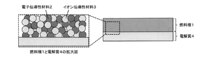
- FIG. 1 schematically shows a cross section of an electrode according to an embodiment of the present invention.
- the fuel electrode of this embodiment is porous and has pores for gas diffusion (fuel electrode 1).
- the fuel electrode 1 contains an electron conductive material 2 and an ionic conductive material 3.
- the porosity of the fuel electrode 1 is 15 to 40% by volume.
- the fuel electrode 1 is formed as a laminated structure with the electrolyte 4 which is an ionic conductive material.
- the electrolyte 4 has a dense layer to prevent gas cross leakage.
- the entire electrolyte 4 may be a dense body.
- the relative density of the dense body layer of the electrolyte 4 with respect to the true density (mass) is 95 to 100%, more preferably 97 to 100%, and particularly preferably 98 to 100%. This is because the gas cross leak prevention function can be further improved.
- the thickness of the dense layer of the electrolyte 4 is 0.1 ⁇ m to 20.0 ⁇ m, more preferably 0.1 ⁇ m to 10.0 ⁇ m, and particularly preferably 0.1 ⁇ m to 5.0 ⁇ m.
- the fuel electrode 1 is placed on the porous support 5 having a higher porosity than the fuel electrode 1, as in the laminated structure shown in FIG. Is formed in.
- the fuel electrode 1 can be formed as a specialized electrode (called an active layer, a catalyst layer, a functional layer, or the like) for reducing the electrode resistance.
- FIG. 3 schematically shows a cross-sectional view of the laminated structure according to the embodiment of the present invention.
- the fuel electrode 1 is formed on the porous support 5, and the electrolyte 4 is formed on the fuel electrode 1.
- a laminated structure having a gas cross leak prevention function of the electrolyte 4, a function of reducing the electrode resistance of the fuel electrode 1, and a function of improving the gas diffusivity and the electrical current collection property of the porous support 5 is formed. can do.
- the fuel electrode for a solid oxide fuel cell of the present invention is a porous body in which an electron conductive material and an ionic conductive material are composited.
- the fuel electrode for a solid oxide fuel cell of the present invention comprises a fired body of a raw material containing an electron conductive material and an ionic conductive material. That is, the fuel electrode for a solid oxide cell of the present invention contains an electron conductive substance and an ion conductive substance, and calcins a raw material mixture containing a powdery electron conductive material and a powdery ion conductive material. It is a fired product obtained by the above.
- the electron conductive material for the fuel electrode refers to a material that can be used in a high temperature reducing atmosphere, has catalytic activity for the oxidation or reduction reaction of the gas on the fuel electrode side, and has the property of conducting electrons. It sometimes contains materials that are reduced to metal.
- the electron conductive material for the fuel electrode is not particularly limited, and examples thereof include iron, nickel, and copper.
- the electron conductive material for the fuel electrode may be one kind alone or a combination of two or more kinds.
- the electron conductive material one or more selected from the group consisting of Ni, Cu, Fe, Co, Mn, Cr, La, Sm, Gd, Ce, Pr, Sr, Ca, and Ba. It is a material composed of one or more of a metal or a metal oxide containing.
- Nickel is preferable as the electronically conductive material for the fuel electrode.
- the ionic conductive material for the fuel electrode refers to a material that can be used in a high temperature reducing atmosphere and has the property of conducting ions.
- the ionic conductive material for the fuel electrode is not particularly limited, and examples thereof include oxides based on zirconia, ceria, and the like.
- the ionic conductive material for the fuel electrode may be one kind alone or a combination of two or more kinds.
- ionic conductive materials include one or more of metal oxides containing one or more selected from the group consisting of Sc, Sr, Zr, Y, Ba, Ce, Sm, Gd, and Yb. It is a material that becomes.
- ZrO 2 (Y 2 O 3 ) stabilized ZrO 2 , (Sc 2 O 3 ) stabilized ZrO 2 , Sm-added CeO 2 , and Gd-added CeO 2 are preferable.
- the average particle size of the primary particles of the electron conductive material according to the fuel electrode for the solid oxide fuel cell of the present invention is 0.001 to 2.00 ⁇ m, preferably 0.005 to 1.00 ⁇ m, and particularly preferably 0.010. It is ⁇ 0.50 ⁇ m.
- the average particle size of the primary particles of the ionic conductive material according to the fuel electrode for the solid oxide fuel cell of the present invention is 0.001 to 2.00 ⁇ m, preferably 0.005 to 1.00 ⁇ m, and particularly preferably 0. It is 010 to 0.50 ⁇ m.
- the contact points between the electron conductive material and the ion conductive material are increased, and the specific surface area in the electrode is increased.
- the reaction field is expanded and the electrode resistance is lowered.
- the particle size means the particle size of the primary particles unless otherwise specified.
- the average particle diameter of the primary particles is determined by X-ray diffraction (eg, manufactured by Rigaku, SmartLab) and Scheller's formula (Scheller constant: 0.9).
- the cross section of the electrode is observed by SEM (eg, Carl Zeiss, Ultra55) and obtained by analyzing the SEM image.
- the population parameter for obtaining the standard deviation and the average particle size of the particle size distribution by analyzing the SEM image is 100 or more.
- the standard deviation of the particle size distribution of the electron conductive material is A 1 ( ⁇ m) and the average particle size of the electron conductive material is B 1 ( ⁇ m)
- a 1 / B 1 ) ⁇ 100 is 0. It is .000 to 20.0, preferably 0.001 to 15.0, and particularly preferably 0.1 to 10.0.
- the standard deviation of the particle size distribution of the ionic conductive material is A 2 ( ⁇ m) and the average particle size of the ionic conductive material is B 2 ( ⁇ m)
- a 2 / B 2 ) ⁇ 100 that is, (standard deviation of particle size distribution of ionic conductive material (A 2 ) / average particle diameter of ionic conductive material (B 2 )) ⁇ 100 is 0. It is .000 to 20.0, preferably 0.001 to 15.0, and particularly preferably 0.1 to 10.0.
- the value of "(standard deviation of particle size distribution / average particle size) x 100" of the electron conductive material and the ionic conductive material is within the above range.
- the mass ratio of the electron conductive material to the ion conductive material is preferably 80:20 to 40 :. It is 60, preferably 70:30 to 50:50, and particularly preferably 65:35 to 55:45.
- the reaction field is expanded by increasing the contact points between the electron conductive material and the ion conductive material, and the electrode resistance is increased. Will be low.
- the fuel electrode for a solid oxide cell of the present invention may contain a material other than the electron conductive material and the ionic conductive material, and the electron contained in the fuel electrode for the solid oxide cell of the present invention may be contained.
- the content of other materials other than the conductive material and the ionic conductive material is in the range of 0 to 20 parts by mass of the other material component when the total mass of the electron conductive material and the ionic conductive material is 100 parts by mass. be.
- the film thickness of the fuel electrode for a solid oxide fuel cell of the present invention is preferably 1.0 ⁇ m to 100.0 ⁇ m, more preferably 1.0 ⁇ m to 30.0 ⁇ m, and particularly preferably 1.0 ⁇ m to 10.0 ⁇ m.
- the film thickness of the fuel electrode is within the above range, the gas diffusion resistance is reduced and the electrode resistance is lowered.
- the porosity of the fuel electrode for a solid oxide fuel cell of the present invention is preferably 15 to 40% by volume, more preferably 18 to 38% by volume, and particularly preferably 20 to 35% by volume. Since the pore ratio of the fuel electrode is within the above range, the occupancy rate of the electron conductive material and the ionic conductive material in the electrode per space is increased while maintaining the diffusivity of the gas, and the reaction field is expanded. , The electrode resistance becomes low.
- the laminated structure of the first aspect of the present invention comprises an electrolyte and a fuel electrode for a solid oxide fuel cell of the present invention laminated with the electrolyte.
- the film thickness of the electrolyte is 0.1 to 20.0 ⁇ m, and the electrolyte is a dense body having a relative density of 95 to 100%. It is a laminated structure characterized by.
- the laminated structure of the second aspect of the present invention comprises a porous support and a fuel electrode for a solid oxide cell of the present invention laminated on the porous support.
- the porosity of the porous support is higher than the porosity of the fuel electrode for the solid oxide fuel cell. It is a laminated structure characterized by.
- a first slurry for producing the fuel electrode for a solid oxide fuel cell is applied onto a porous support, and then a second slurry for producing the electrolyte is applied.
- a method for producing a laminated structure which comprises a step of applying a slurry and then firing at a first temperature to form a porous support, a fuel electrode, and an electrolyte.
- the solid oxide fuel cell of the present invention is a solid oxide fuel cell having the fuel electrode for the solid oxide cell of the present invention.
- the solid oxide cell of the present invention is a solid oxide cell characterized by having a laminated structure of the first form or the second form of the present invention.
- a first slurry for producing a fuel electrode for a solid oxide fuel cell is applied onto a porous support, and then the electrolyte is produced.
- the material for forming the electrolyte refers to a material that has the property of conducting ions such as oxide ions and protons.
- the material for the electrolyte is not particularly limited, and for example, an oxide having oxide ion conductivity such as a zirconia oxide or a ceria oxide, an oxide having proton conductivity such as a perovskite type oxide, or the like. Can be mentioned.
- the material for the electrolyte may be one kind alone or a combination of two or more kinds.
- materials for electrolytes include one or more selected from the group consisting of Ca, Sc, Sr, Ga, Y, Zr, In, Ba, La, Ce, Pr, Sm, Gd, Yb. It is a material consisting of one or more kinds of metals or metal oxides contained therein.
- As the material for the electrolyte ZrO 2 type oxide, LaGaO 3 type oxide, BaZrO 3 type oxide, and BaCeO 3 type oxide are preferable.
- the material for forming the intermediate layer refers to a material that conducts ions such as oxide ions and protons and has high chemical stability with the electrolyte material and the air electrode material.
- the material for the intermediate layer is not particularly limited, and examples thereof include zirconia-based oxides, ceria-based oxides, and perovskite-type oxides.
- the material for the intermediate layer may be one kind alone or a combination of two or more kinds.
- the material for the intermediate layer one or more selected from the group consisting of Ca, Sc, Sr, Ga, Y, Zr, In, Ba, La, Ce, Pr, Sm, Gd, Yb. It is a material composed of one or more of a metal or a metal oxide containing.
- the material for the intermediate layer CeO 2 based oxide.
- the material for forming an air electrode refers to a material that conducts electrons or holes and has a property of having catalytic activity in an air electrode reaction.
- the material for forming the air electrode is not particularly limited, and examples thereof include perovskite-type oxides and the like.
- the material for forming the air electrode may be one kind alone or a combination of two or more kinds.
- More specific examples of materials for forming air electrodes are Ca, Sc, Cr, Mn, Fe, Co, Ni, Cu, Sr, Ga, Y, Zr, In, Ba, La, Ce, Pr. , Sm, Gd, Yb, and one or more of metals or metal oxides containing one or more selected from the group.
- the material for forming the air electrode LaMnO 3 series oxide, LaCoO 3 series oxide, SmCoO 3 series oxide, and (La, Sr) (Co, Fe) O 3 series oxide are preferable.
- the fuel electrode, the laminated structure, and the solid oxide fuel cell of the present embodiment are suitably manufactured by the manufacturing method shown below.
- the fuel electrode that is, the fuel electrode 1, which is the product of the present invention, is formed as a laminated structure with the electrolyte 4.
- the electrolyte 4 is generally a dense body to prevent gas leaks.
- the fuel electrode that is, the fuel electrode 1, which is the product of the present invention, is formed as a laminated structure of the electrolyte 4 and the porous support 5.
- the porous support 5 has a higher porosity than the fuel electrode 1 in order to enhance gas diffusivity.
- the raw material for the fuel electrode 1 is an oxide powder material.
- the average particle size of the primary particles when formed as a fuel electrode can be controlled by the particle size, the dispersed state, the firing temperature, or the combination of the composite materials of the oxide powder material.
- the amount of the binder, plasticizer, or dispersant added or the firing temperature is changed, or carbon, cellulose, or a polymer-based pore-forming agent is additionally mixed to form the fuel electrode 1. Porosity can be controlled.
- the method for producing the laminated structure 4 is, for example, to apply a first slurry for producing the fuel electrode 1 on the porous support 5, then apply a second slurry for producing the electrolyte 4, and then apply the second slurry. It is provided with a process of forming a laminated structure of a porous support 5, a fuel electrode 1, and an electrolyte 4 by co-firing at a first temperature.
- the porous support 5 has good electrical conductivity and gas diffusivity.
- the porosity of the porous support 5 is, for example, 10 to 60% by volume, more preferably 30 to 57%, and particularly preferably 40 to 50%. When the porosity of the porous support is within the above range, good electrical conductivity and gas diffusibility can be maintained.
- the shape of the porous support 5 may be a flat plate shape, a tube shape, or the like, but is not particularly limited. Examples of the material of the porous support 5 include oxides such as alumina and zirconia, and heat-resistant metals.
- the fuel electrode includes one or more metal oxides including at least one of the group consisting of Sc, Sr, Zr, Y, Ba, Ce, Sm, Gd, and Yb, which are ionic conductive materials, and electrons.
- the first slurry which is a fuel electrode material
- the second slurry which is an electrolyte material
- co-firing at the first temperature causes a thin-film dense electrolyte.
- a layer is obtained. That is, a laminate having an electrolyte 4 which is a thin film dense electrolyte layer, a fuel electrode 1 formed on one surface of the electrolyte 4, and a porous support 5 which is a support thereof can be obtained.
- the electrolyte can be shrunk together with the porous support 5 and the fuel electrode 1, and a dense electrolyte layer having a high relative density can be obtained.
- Examples of the first slurry coating method include a screen printing method, a spray coating method, a transfer method, and a dip coating method. Sintering of this coating film proceeds by firing at the first temperature, and the film thickness of the fuel electrode 1 obtained after firing is 1.0 ⁇ m to 100.0 ⁇ m, preferably 1.0 ⁇ m to 30.0 ⁇ m, particularly. It is preferably 1.0 ⁇ m to 10.0 ⁇ m.
- Examples of the second slurry coating method include a screen printing method, a spray coating method, a transfer method, and a dip coating method.
- a coating film having a high molding density can be obtained by optimizing the particle dispersibility of the electrolyte material in the second slurry. Sintering of this coating film proceeds by firing at the first temperature, and the film thickness of the electrolyte 4 obtained after firing is 0.1 to 20.0 ⁇ m, preferably 0.1 ⁇ m to 10.0 ⁇ m, particularly preferably. Is 0.1 ⁇ m to 5.0 ⁇ m.
- the electrolyte 4 In order to reduce the electrical resistance, it is preferable to make the electrolyte 4 as thin as possible. On the other hand, the extreme thinning causes a gas leak due to a defect in the electrolyte 4. Therefore, it is appropriate that the electrolyte 4 has a film thickness of 0.1 ⁇ m or more in order to prevent defects, and the film thickness of the electrolyte 4 is 20 ⁇ m or less so that the electric resistance of the electrolyte 4 can be 1 ⁇ 2 or less of the total electric resistance of the solid oxide fuel cell.
- the firing temperature of these coating films is preferably 1250 to 1500 ° C, more preferably 1300 to 1450 ° C, and particularly preferably 1350 to 1400 ° C. This is because the sintering of the coating film proceeds sufficiently at a firing temperature of 1250 ° C. or higher, and a dense electrolyte can be obtained. Further, when the firing temperature is 1500 ° C. or lower, the diffusion of the elements and the volatilization of the elements constituting the electrolyte 4 are suppressed.
- the firing time of the coating film is preferably 1 to 8 hours, more preferably 2 to 6 hours, and particularly preferably 3 to 4 hours.
- FIG. 3 schematically shows a cross-sectional view of a solid oxide fuel cell according to an embodiment of the present invention.
- the solid oxide fuel cell according to the embodiment of the present invention includes the fuel electrode 1, the electrolyte 4, and the porous support 5 of the present invention. Further, an intermediate layer 6 and an air electrode 7 are provided on the electrolyte 4 as an intermediate layer for preventing a reaction.
- a first slurry is applied onto a porous support 5, a second slurry is applied, and then co-baking is performed at a first temperature.
- a step of forming the fuel electrode 1 and the electrolyte 4 a step of applying the third slurry on the electrolyte 4, and then firing at a second temperature to form the intermediate layer 5, and a step of forming the fourth slurry on the intermediate layer 5. It is provided with a step of applying and then firing at a third temperature to form an air electrode 7.
- the first slurry is applied onto the porous support 5, then the second slurry is applied, and then co-firing at the first temperature is performed to make the fuel electrode 1. And the step of forming the electrolyte 4, and the step of applying the fourth slurry on the electrolyte 4 and then firing at the third temperature to form the air electrode 7.
- the porosity, material, and mixed mass ratio of the porous support 5 are the same as those described in the fuel electrode manufacturing method.
- the method for applying the first slurry and the film thickness of the fuel electrode 1 are the same as the method for applying the first slurry and the film thickness of the fuel electrode 1 in the method for manufacturing the fuel electrode.
- the method for applying the second slurry and the film thickness of the electrolyte 4 are the same as the method for applying the second slurry and the film thickness of the electrolyte 4 in the method for producing the fuel electrode.
- the preferable range of the first temperature, which is the co-firing temperature of the fuel electrode 1 and the electrolyte 4, and the reason thereof are the preferable range of the firing temperature of the coating film, which is the material of the fuel electrode 1 and the electrolyte 4, in the method of manufacturing the fuel electrode.
- the reason is the same.
- the preferable range of the co-firing time and the reason thereof are the same as the preferable range of the firing time of the coating film which is the material of the fuel electrode 1 and the electrolyte 4 in the method for producing the fuel electrode and the reason thereof.
- the intermediate layer 6 can be either a dense body or a porous body, but it is desirable that the intermediate layer 6 has a high relative density in order to enhance the reaction prevention function. Specifically, 60 to 100% is preferable, 70 to 100% is more preferable, and 80 to 100% is particularly preferable. Further, the intermediate layer 6 may form a solid oxide fuel cell without the intermediate layer 6 when the chemical stability of the electrolyte 4 and the air electrode 7 is high (when the reaction prevention function is not required). can.
- Examples of the method for applying the third slurry include a screen printing method, a spray coating method, a transfer method, and a dip coating method.
- a coating film having a high molding density can be obtained by optimizing the particle dispersibility of the intermediate layer material in the third slurry. Sintering of this coating film proceeds by firing at a second temperature, and the film thickness of the intermediate layer 6 obtained after firing is preferably 0.1 to 10 ⁇ m.
- the intermediate layer 6 is made as thin as possible in order to reduce the electrical resistance.
- the extremely thin film impairs the reaction prevention function of the intermediate layer 6. Therefore, the thickness of the intermediate layer 6 is 0.1 ⁇ m or more in order to maintain the reaction prevention function, and the electric resistance of the intermediate layer 5 is 10 ⁇ m or less so that the electric resistance of the intermediate layer 5 can be 1/2 or less of the total electric resistance of the solid oxide fuel cell. Is appropriate.
- the firing temperature of the coating film is preferably 1000 to 1400 ° C, more preferably 1100 to 1350 ° C, and particularly preferably 1150 to 1300 ° C. This is because a good sintered state can be obtained and the influence of mutual diffusion of elements with the electrolyte 4 can be suppressed.
- the firing time of the coating film is preferably 0.5 to 4 hours, more preferably 1 to 3 hours, and particularly preferably 1 to 2 hours.
- Examples of the method for applying the fourth slurry include a screen printing method, a spray coating method, a transfer method, and a dip coating method. Sintering of this coating film proceeds by firing at a third temperature, and the film thickness of the air electrode 7 obtained after firing is preferably 1 to 100 ⁇ m.
- the air electrode 7 is formed on the electrolyte 4 or the intermediate layer 6.
- the air electrode 7 preferably contains a perovskite-type oxide material as the electron conductive material.
- the air electrode 7 is a material in which an electron conductive material and an ionic conductive material are mixed or composited.
- the third temperature, which is the firing temperature of the air electrode 7, is preferably 700 to 1200 ° C, more preferably 800 to 1100 ° C, and particularly preferably 850 to 1050 ° C.
- the firing time is preferably 0.5 to 8 hours, more preferably 1 to 6 hours, and particularly preferably 1 to 3 hours.
- the solid oxide fuel cell is a device in which a fuel electrode 1, an electrolyte 4, an intermediate layer 6 if necessary, an air electrode 7, and a porous electrode if necessary are formed on a porous support 5 as a support. Is.
- the oxide powder material which is the raw material of the fuel electrode, was produced by the spray pyrolysis method.
- the spray pyrolysis method is one of the methods capable of synthesizing nano-sized oxide powder materials. It is possible to synthesize a single oxide powder material, but it is also possible to synthesize an oxide powder material in which two or more kinds of oxides are combined. At this time, a good dispersed state can be obtained in two or more kinds of composite oxides. Another feature is that the primary particle size can be controlled in a wide range.
- the synthesis of the oxide powder material by the spray pyrolysis method in the examples will be described.
- a spray aqueous solution containing a metal salt of an electron conductive material source for a fuel electrode and a metal salt of an ionic conductive material source is prepared, and the spray aqueous solution is atomized by ultrasonic vibration.
- the oxide powder material for the air electrode is obtained by introducing the atomized aqueous solution for spraying into a heating furnace.
- the composition ratio of various metal elements constituting the primary particles of the electron conductive material for the fuel electrode and the primary particles of the ionic conductive material was adjusted.
- the spraying aqueous solution in the spraying device is atomized by ultrasonic vibration (frequency: 1.75 MHz), and then the atomized aqueous solution is atomized by flowing with the air of the carrier gas through a pipe connected to the spraying device. Introduced into a heating furnace.
- the metal salt of the electron conductive material source for the fuel electrode and the metal salt of the ionic conductive material source in the spray aqueous solution were thermally decomposed and oxidized to obtain an oxide powder material for the fuel electrode.
- a heating furnace As a heating furnace, a 4-stage electric furnace is used, the temperature inside the furnace of each stage is 300, 500, 700, 900 ° C from the previous stage, and the heating time at each stage (passing time in the furnace of each stage) is 8 from the previous stage. Seconds, 8 seconds, 8 seconds, 8 seconds).
- Aqueous solution for spraying s1 Weigh 18.542 g of nickel nitrate hexahydrate, 8.910 g of zirconyl dihydrate dihydrate, and 2.221 g of yttrium hexahydrate nitrate, dissolve in pure water, and then make the amount of the aqueous solution 1000 ml. Further, pure water was added to prepare an aqueous solution for spraying s1.
- 0.1 mol of 50% by mass NiO-50% by mass (ZrO 2 ) 0.92 (Y 2 O 3 ) 0.08 (hereinafter, YSZ) is synthesized per 1 L.
- Aqueous solution for spraying s2 Weigh 21.089 g of nickel nitrate hexahydrate, 6.756 g of zirconyl dihydrate dihydrate, and 1.684 g of yttrium hexahydrate nitrate, dissolve in pure water, and then make the amount of the aqueous solution 1000 ml. Further, pure water was added to prepare an aqueous solution for spraying s2. By spray pyrolyzing the aqueous spray solution s1, 0.1 mol of 60% by mass NiO-40% by mass YSZ can be synthesized per liter.
- Aqueous solution for spraying s3 Weigh 23.384 g of nickel nitrate hexahydrate, 4.816 g of zirconyl dihydrate dihydrate, and 1.200 g of ittrium hexahydrate nitrate, dissolve in pure water, and then make the amount of the aqueous solution 1000 ml. Further, pure water was added to prepare an aqueous solution for spraying s3. By spray pyrolyzing the aqueous spray solution s1, 0.1 mol of 70% by mass NiO-30% by mass YSZ can be synthesized per liter.
- Aqueous solution for spraying s4 Weighing 14.72 g of strontium nitrate hexahydrate, 4.63 g of strontium nitrate, 12.73 g of cobalt nitrate hexahydrate, and 19.54 g of cerium nitrate hexahydrate, otherwise the same as the spray aqueous solution s1.
- an aqueous solution for spraying s4 was prepared.
- spray pyrolyzing the aqueous spray solution s4 0.1 mol of 50% by mass SSC-50% by mass SDC can be synthesized per liter.
- the spraying aqueous solution s4 is used to produce an air electrode.
- Oxide powder material p1 Using the spray aqueous solution s1, spray pyrolysis was performed by an ultrasonic spray pyrolysis method to obtain an oxide powder material p1 of NiO-YSZ.
- Oxide powder material p2 Using the spray aqueous solution s2, the oxide powder material p2 of NiO-YSZ was obtained by the same method as the oxide powder material p1.
- Oxide powder material p3 Using the spray aqueous solution s3, the oxide powder material p3 of NiO-YSZ was obtained by the same method as the oxide powder material p1.
- Oxide powder material p4 Using the spray aqueous solution s4, the oxide powder material p4 of SSC-SDC was obtained by the same method as the oxide powder material p1.
- any of the NiO-YSZ oxide powder materials could be identified as NiO and YSZ.
- a diffraction peak was observed, and it was confirmed that the material was a powder material containing crystalline NiO and YSZ.
- X-ray diffraction analysis of the oxide powder material p4 of the SSC-SDC was performed, diffraction peaks that could be identified as SSC and SDC were observed, and it was confirmed that the powder material contained crystalline SSC and SDC. did it.
- the particle size distribution of the oxide powder materials p1 to p4 was measured by a laser diffraction type particle size distribution measurement method (Microtrac HRA9320-X100 manufactured by Nikkiso Co., Ltd.), and the volume-based 10% particle size (D10) was measured. The values of 50% particle size (D50) and 90% particle size (D90) based on the volume were determined.
- the oxide powder material is an aggregate secondary particle in which finer primary particles are composited, and the particle size distribution measured here is a value in the aggregate secondary particle. The results are shown below.
- the average particle size of the primary particles of the oxide powder materials p1 to p4 was determined by the peak width at half maximum of X-ray diffraction (SmartLab, manufactured by Rigaku) and the Scheller's formula (Scheller constant: 0.9). As a result, any of the primary particles of NiO, YSZ, SSC, and SDC synthesized as the primary particles was about 15 nm.
- NiO manufactured by Sumitomo Metal Mining Co., Ltd.
- YSZ manufactured by TZ-8YS, manufactured by Tosoh
- the pore-forming agent was a mixture of carbon and cellulose in a ratio of 2: 1 and was added in an amount of 25% by mass based on the sum of the masses of NiO and YSZ.
- the above mixture was molded into a flat plate-shaped green sheet having a width of 120 mm and a thickness of 0.7 mm by an extrusion molding method.
- the green sheet was cut out to a diameter of 32 mm using a punching punch, and then fired at 1240 ° C. for 2 hours in an air atmosphere to obtain a porous support calcined body.
- ⁇ Preparation of slurry for fuel electrode> A mixture of ethyl cellulose, a plasticizer, a dispersant, and ⁇ -terepineol with the oxide powder material p1 is kneaded in a kneader at room temperature for 1 minute and 30 seconds to obtain a fuel electrode slurry S1. Obtained.
- Slurry for fuel electrode S2 A mixture of ethyl cellulose, a plasticizer, a dispersant, and ⁇ -terepineol with the oxide powder material p2 is kneaded at room temperature for 1 minute and 30 seconds in a kneader to obtain a fuel electrode slurry S2. Obtained.
- YSZ powder (TZ-8Y, manufactured by Tosoh) mixed with ethyl cellulose, plasticizer, dispersant, and ⁇ -terepineol is kneaded in a kneader at room temperature for 1 minute and 30 seconds for electrolytes. A slurry was obtained.
- a slurry for an intermediate layer was obtained by kneading in a vessel at room temperature for 1 minute and 30 seconds.
- a slurry of an air electrode is obtained by kneading the oxide powder material p4 with ethyl cellulose, a plasticizer, a dispersant, and ⁇ -terepineol in a kneader at room temperature for 1 minute and 30 seconds. rice field.
- Example 1 The fuel electrode slurry S1 is applied onto the porous support calcined body by a screen printing method, and then the fuel electrode slurry S1 is applied onto the porous support calcined body. After applying the slurry for electrolytes by a screen printing method, the slurry was fired at 1360 ° C. for 3 hours in an air atmosphere to obtain a laminated structure of an electrolyte, a fuel electrode and a porous support. Then, the slurry for an intermediate layer was applied onto the electrolyte of the laminated structure by a screen printing method, and then calcined at 1300 ° C. for 1 hour in an air atmosphere to obtain an intermediate layer. Then, an air electrode slurry was applied onto the intermediate layer by a screen printing method, and then calcined at 900 ° C. for 1 hour in an air atmosphere to obtain an air electrode. As described above, the solid oxide fuel cell of Example 1 was produced.
- Example 2 After applying the fuel electrode slurry S2 on the porous support calcined body by a screen printing method, the fuel electrode slurry S2 coated on the porous support calcined body is then coated with the fuel electrode slurry S2.
- the slurry was fired at 1360 ° C. for 3 hours in an air atmosphere to obtain a laminated structure of an electrolyte, a fuel electrode and a porous support.
- the slurry for an intermediate layer was applied onto the electrolyte of the laminated structure by a screen printing method, and then calcined at 1300 ° C. for 1 hour in an air atmosphere to obtain an intermediate layer.
- an air electrode slurry was applied onto the intermediate layer by a screen printing method, and then calcined at 900 ° C. for 1 hour in an air atmosphere to obtain an air electrode.
- the solid oxide fuel cell of Example 2 was produced.
- Example 3 After applying the fuel electrode slurry S3 on the porous support calcined body by a screen printing method, the fuel electrode slurry S3 coated on the porous support calcined body is then coated with the fuel electrode slurry S3.
- the slurry was fired at 1360 ° C. for 3 hours in an air atmosphere to obtain a laminated structure of an electrolyte, a fuel electrode and a porous support.
- the slurry for an intermediate layer was applied onto the electrolyte of the laminated structure by a screen printing method, and then calcined at 1300 ° C. for 1 hour in an air atmosphere to obtain an intermediate layer.
- an air electrode slurry was applied onto the intermediate layer by a screen printing method, and then calcined at 900 ° C. for 1 hour in an air atmosphere to obtain an air electrode.
- the solid oxide fuel cell of Example 3 was produced.
- the film thickness of each member was about 0.55 mm for the porous support, about 5.0 ⁇ m for the fuel electrode, and about 3. for the electrolyte. It is 0 ⁇ m, the intermediate layer is about 2.0 ⁇ m, and the air electrode is about 30.0 ⁇ m.
- the film thickness of the fuel electrode is 4.0 ⁇ m at the thinnest part and 6.0 ⁇ m at the thickest part, and 4.0 ⁇ m at the thinnest part and 6 at the thickest part in Example 2. It was 0.0 ⁇ m, and in Example 3, it was 4.0 ⁇ m at the thinnest part and 6.0 ⁇ m at the thickest part.
- Example 1 the film thickness of the electrolyte was 2.5 ⁇ m at the thinnest part and 3.5 ⁇ m at the thickest part, and 2.5 ⁇ m at the thinnest part and 3.5 ⁇ m at the thickest part in Example 2. In Example 3, the thickness was 2.5 ⁇ m at the thinnest part and 3.5 ⁇ m at the thickest part.
- Comparative Example 1 The electrolyte slurry is applied onto the porous support calcined body by a screen printing method, and then fired at 1360 ° C. for 3 hours in an air atmosphere to obtain a laminated structure of the electrolyte and the porous support. rice field. Then, the slurry for an intermediate layer was applied onto the electrolyte of the laminated structure by a screen printing method, and then calcined at 1300 ° C. for 1 hour in an air atmosphere to obtain an intermediate layer. Then, an air electrode slurry was applied onto the intermediate layer by a screen printing method, and then calcined at 900 ° C.
- the solid oxide fuel cell of Comparative Example 1 was produced.
- the porous support since the material of the porous support is NiO-YSZ, the porous support is a support and at the same time functions as a fuel electrode of a solid oxide fuel cell in an electrochemical reaction. do.
- the film thickness of each member in the solid oxide cell of Comparative Example 1 is about 0.55 mm for the porous support, about 3.0 ⁇ m for the electrolyte, about 2.0 ⁇ m for the intermediate layer, and about 30.0 ⁇ m for the air electrode. Is.
- the porous support also serves as a fuel electrode.
- the film thickness of the electrolyte was 2.5 ⁇ m at the thinnest part and 3.5 ⁇ m at the thickest part.
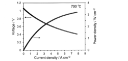
- Table 1 shows the results of power generation characteristic measurement (maximum output density) and the results of AC impedance measurement (electrode resistance) in the solid oxide fuel cell of Examples 1 to 3 and Comparative Example 1.
- the cell electrode resistance is the call-call plot of the cell to be measured obtained by the AC impedance method, that is, the real part resistance value Z'( ⁇ ) and the imaginary part resistance for each frequency when the frequency is changed.
- the real part resistance value Z'( ⁇ ) the real part resistance value Z'( ⁇ ) and the imaginary part resistance for each frequency when the frequency is changed.
- the real part of the two sections with the horizontal axis of the graph It is the difference in resistance value.
- FIG. 7 shows an image of the fuel electrode observed by LV-SEM (Ultra55, manufactured by Carl Zeiss) after the cross-sectional processing.
- the porosity of each fuel electrode was measured from the contrast of each LV-SEM image by image processing using image analysis software (WinROOF2018, manufactured by Mitani Corporation). Further, the particle diameters of the observed Ni particles and YSZ particles were measured on the image using the same image analysis software, and the average particle diameter of each material and its standard deviation were obtained.
- Examples 1 to 3 showed high maximum power density and low electrode resistance with respect to Comparative Example 1. This is because the electron conductive material and the ionic conductive material are contained in a specific range of mass ratio as the fuel electrode material, and the average particle size and the particle size distribution in each of the electron conductive material and the ionic conductive material. By setting the film thickness and porosity within specific ranges, the electrode resistance of the fuel electrode is dramatically reduced, and as a result, a high maximum output density is realized.
- the porous supports of Examples 1 to 3 are made of the same material as Comparative Example 1, the measurement results of Comparative Example 1 shown in Table 2 are the porous supports of Examples 1 to 3. It corresponds to each physical property value (porosity, average particle size, standard deviation of particle size distribution).
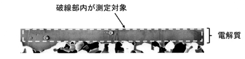
- FIG. 8 shows an image of Example 2 in which the electrolyte was observed with an LV-SEM (Ultra55, manufactured by Carl Zeiss) after performing the above cross-sectional treatment.
- the relative density of the electrolyte was measured from the contrast of the LV-SEM image by performing image processing using image analysis software (WinROOF2018, manufactured by Mitani Corporation).
- WinROOF2018 image analysis software
- the relative density of Example 2 was 99%.
- the relative densities of the electrolytes of Examples 1 and 3 and Comparative Example 1 measured in the same manner were also 99%.
- a fuel electrode for a solid oxide fuel cell and a solid oxide fuel cell having excellent performance with a low electrode resistance of the fuel electrode.
Landscapes
- Chemical & Material Sciences (AREA)
- Engineering & Computer Science (AREA)
- Chemical Kinetics & Catalysis (AREA)
- Electrochemistry (AREA)
- General Chemical & Material Sciences (AREA)
- Manufacturing & Machinery (AREA)
- Life Sciences & Earth Sciences (AREA)
- Sustainable Development (AREA)
- Sustainable Energy (AREA)
- Materials Engineering (AREA)
- Fuel Cell (AREA)
- Inert Electrodes (AREA)
Abstract
電極抵抗が低い固体酸化物形セル用燃料極を提供する。 固体酸化物形セル用燃料極であって、電子伝導性材料及びイオン伝導性材料を含有する原料の焼成体からなり、該電子伝導性材料の平均粒子径が0.001~2.00μmであり、且つ、該イオン伝導性材料の平均粒子径が0.001~2.00μmであり、該電子伝導性材料の粒子径分布の標準偏差をA1(μm)、該電子伝導性材料の平均粒子径をB1(μm)としたときに、(A1/B1)×100の値が0.000~20.0であり、該イオン伝導性材料の粒子径分布の標準偏差をA2(μm)、該イオン伝導性材料の平均粒子径をB2(μm)としたときに、(A2/B2)×100の値が0.000~20.0であること、を特徴とする固体酸化物形セル用燃料極である。
Description
本発明は、固体酸化物形セル用燃料極、積層構造体及びその製造方法、並びに固体酸化物形セル及びその製造方法に関する。
固体酸化物形セルは、高効率エネルギー変換を可能とするデバイスとしての実用化に向けた研究開発が進められている。固体酸化物形セルを用いたデバイスの代表例として、固体酸化物形燃料電池や固体酸化物形電解セル等が挙げられる。固体酸化物形セルは、酸化物を主な材料とする緻密体の電解質を、空気極と燃料極の2つの多孔質体の電極で挟み込んで構成される。
固体酸化物形セルは、構成材料により幅広い作動温度領域を選択でき、400~1000℃で使用される。
電荷担体となるイオンは、主に酸化物イオンとプロトンである。酸化物イオンを伝導する電解質材料は酸化物イオン伝導性電解質と、プロトンを伝導する電解質材料はプロトン伝導性電解質とそれぞれ呼ばれる。酸化物イオン伝導性電解質としてはジルコニア系やセリア系材料等が、プロトン伝導性電解質としてはペロブスカイト型酸化物材料等が、代表例としてそれぞれ挙げられる。
電極の材料は、触媒活性を有する電子伝導性の酸化物や金属が用いられる(以下、「電子伝導性材料」という)。電子伝導性材料は、単体で用いられる場合もあるが、電極の反応場拡大、熱膨張係数調整や機械的強度向上のために、電解質と同じ材料又は電解質と同じイオン(「イオン」は、酸化物イオンやプロトンを含む伝導キャリアとなる全てのイオンの総称)を伝導するイオン伝導性材料が、電子伝導性材料と混合して用いられることもある。一般的には、電子伝導性材料とイオン伝導性材料が混合されることで、電極の反応抵抗が低減される。なお、反応抵抗は、電極単位面積あたりの反応場の広さ(又は反応活性点の量)と反応場あたりの活性に依存する。
電子伝導性材料とイオン伝導性材料の混合について、少なくとも1つ以上の材料の平均粒径が1μm以下である場合の混合を複合と呼び、複合化することにより電極の反応抵抗低減の効果が顕著に得られる。
電極は多孔質体であることにより、電極内の反応場に、電気化学反応に必要なガスを供給し、また電気化学反応により生成したガスを除去(ガスの供給や除去を、以下、「ガス拡散」という)することができる。ガス拡散に伴い生じる電極内の抵抗をガス拡散抵抗と呼ぶ。実用上、ガスが拡散するためには、気孔をガスが移動できる開気孔とすることが必要であり、そのためには電極の気孔率を少なくとも15体積%を超えるようにすることが必要である。実際の電極設計としては、ガス拡散抵抗を十分に低減するために気孔率を40体積%程度とすることが多い。
上記の電極の反応抵抗とガス拡散抵抗を合せた抵抗を、電極抵抗と呼ぶ。
固体酸化物形セルの空気極用の電子伝導性材料としては、ペロブスカイト型の酸化物材料、例えば、(LaSr)MnO3、(LaSr)FeO3、(LaSr)CoO3、(LaSr)(CoFe)O3等がある。上記電子伝導性材料のLaは他のランタノイド(Pr、Sm、Gd)と置換又は一部置換が可能であり、Srは他のアルカリ土類金属(Ca、Ba)と置換又は一部置換が可能である。
固体酸化物形セルの燃料極用の電子伝導性材料としては、金属系材料(Ti、Mn、Fe、Co、Ni、Cu等)が使用される。金属系材料は、水素、一酸化炭素、炭化水素、及びバイオ燃料等のガスにより還元されたものも含む。例えば、製造時の材料としてNiO(酸化物)が用いられている場合、固体酸化物形セルが構築され、上記ガスにより動作される際には、NiOはNi(金属)に還元される。
固体酸化物形セルの普及に向けての重要な課題として、コスト低減に直結する単位体積あたりのエネルギー変換性能の向上が挙げられる。そして、固体酸化物形セルの単位体積あたりのエネルギー変換性能の重要な要因となるのが、電極単位面積あたりの電流(以下、「電流密度」という)であり、現在も電流密度の増加を目指し、様々な研究開発が進められている。
固体酸化物形セルの電流密度を決定する支配的な要因は、上記の電極抵抗である。電極で起こる電気化学反応とガス拡散に伴い、過電圧(平衡状態と作動状態の電圧差)が生じるが、高効率作動の観点から、低い過電圧でも高い電流密度を得ることができる低電極抵抗の電極が要求される。
特に燃料極は、空気極と比較して高温での焼成により製造され、粒成長が起こることにより、反応に有効な表面積(反応場)が減少し、電極抵抗が大きくなることが課題であった。
これまでの研究開発としては、例えば、電子伝導性材料とイオン伝導性材料の平均粒子径を制御することで、燃料極の電極抵抗を低減することが開示されている(特許文献1)。また、電子伝導性材料とイオン伝導性材料を混合し、さらに気孔率と気孔径を大きくすることで電極抵抗を低減し、高い電流密度を得ることができる燃料極が開示されている(特許文献2)。一定の効果は確認できていいるものの、固体酸化物形セルのコスト低減と普及を促進するためには、さらに燃料極の電極抵抗を低減する技術が必要となっていた。
以上のように、固体酸化物形セルのコスト低減・普及促進のためには、電極抵抗を従来技術と比較し飛躍的に低減させることが必要である。そして、上述したように、さらに電極抵抗を低減させ、より高い電流密度を実現することが求められている。
従って、本発明は、電極抵抗が低い固体酸化物形セル用燃料極を提供することを目的とする。また、本発明は、高い電流密度を実現する固体酸化物形セルを提供することを目的とする。
本発明者らは、電極抵抗を著しく低減することができる燃料極を実現するために、燃料極の材料と構造を制御することにより多くの燃料極試料を試作し、その性能評価を重ねた結果、燃料極材料として、電子伝導性材料及びイオン伝導性材料を含有し、各材料が特定の粒子径であり、特定の粒子径分布を有することにより、燃料極の電極抵抗を飛躍的に低減できること、更に、特定の膜厚とすること、あるいは、特定の気孔率とすることで、燃料極の電極抵抗が更に低減できることを見出し、本発明を開発するに至った。
上記課題を解決するために、本発明は、以下のことを特徴としている。
(1)固体酸化物形セル用燃料極であって、
電子伝導性材料及びイオン伝導性材料を含有する原料の焼成体からなり、
該電子伝導性材料の平均粒子径が0.001~2.00μmであり、且つ、該イオン伝導性材料の平均粒子径が0.001~2.00μmであり、
該電子伝導性材料の粒子径分布の標準偏差をA1(μm)、該電子伝導性材料の平均粒子径をB1(μm)としたときに、(A1/B1)×100の値が0.000~20.0であり、
該イオン伝導性材料の粒子径分布の標準偏差をA2(μm)、該イオン伝導性材料の平均粒子径をB2(μm)としたときに、(A2/B2)×100の値が0.000~20.0であること、
を特徴とする固体酸化物形セル用燃料極。
(2)膜厚が1.0μm~100.0μmであり、気孔率が15~40体積%であることを特徴とする請求項1記載の固体酸化物形セル用燃料極。
(3)前記電子伝導性材料が、Ni、Cu、Fe、Co、Mn、Cr、La、Sm、Gd、Ce、Pr、Sr、Ca、及びBaからなる群から選ばれる1つ以上を含む金属又は金属酸化物の1種以上であり、
前記イオン伝導性材料が、Sc、Sr、Zr、Y、Ba、Ce、Sm、Gd、及びYbからなる群から選ばれる1つ以上を含む金属酸化物の1種以上であり、
前記電子伝導性材料と前記イオン伝導性材料の質量比(電子伝導性材料の質量:イオン伝導性材料の質量)が、80:20~40:60であること、
を特徴とする請求項1記載の固体酸化物形セル用燃料極。
(4)電解質と、該電解質と積層された請求項1~3のいずれか1項記載の固体酸化物形セル用燃料極と、からなり、
該電解質の膜厚が0.1~20.0μmであり、該電解質は、相対密度が95~100%の緻密体であること、
を特徴とする積層構造体。
(5)多孔質支持体と、該多孔質支持体上に積層された請求項1~3のいずれか1項に記載の固体酸化物形セル用燃料極と、からなり、
該多孔質支持体の気孔率が、該固体酸化物形セル用燃料極の気孔率より高いこと、
を特徴とする積層構造体。
(6)請求項1~3のいずれか1項に記載の燃料極を有することを特徴とする固体酸化物形セル。
(7)請求項4又は5記載の積層構造体を有することを特徴とする固体酸化物形セル。
(8)多孔質支持体上に、前記固体酸化物形セル用燃料極を作製するための第1スラリーを塗布し、次いで、前記電解質を作製するための第2スラリーを塗布し、次いで、第1温度で焼成して、多孔質支持体と燃料極と電解質を形成する工程を有することを特徴とする積層構造体の製造方法。
(9)多孔質支持体上に、前記固体酸化物形セル用燃料極を作製するための第1スラリーを塗布し、次いで、前記電解質を作製するための第2スラリーを塗布し、次いで、第1温度で焼成して、多孔質支持体と燃料極と電解質を形成する工程と、
形成された電解質上に中間層を形成するための第3スラリーを塗布し、次いで、第2温度で焼成して、中間層を形成する工程と、
形成された中間層上に空気極を作製するための第4スラリーを塗布し、次いで、第3温度で焼成して、空気極を形成する工程と、
を有することを特徴とする固体酸化物形セルの製造方法。
なお、本明細書において、数値範囲を「~」を用いて示す時、その両端の数値を含む。
電子伝導性材料及びイオン伝導性材料を含有する原料の焼成体からなり、
該電子伝導性材料の平均粒子径が0.001~2.00μmであり、且つ、該イオン伝導性材料の平均粒子径が0.001~2.00μmであり、
該電子伝導性材料の粒子径分布の標準偏差をA1(μm)、該電子伝導性材料の平均粒子径をB1(μm)としたときに、(A1/B1)×100の値が0.000~20.0であり、
該イオン伝導性材料の粒子径分布の標準偏差をA2(μm)、該イオン伝導性材料の平均粒子径をB2(μm)としたときに、(A2/B2)×100の値が0.000~20.0であること、
を特徴とする固体酸化物形セル用燃料極。
(2)膜厚が1.0μm~100.0μmであり、気孔率が15~40体積%であることを特徴とする請求項1記載の固体酸化物形セル用燃料極。
(3)前記電子伝導性材料が、Ni、Cu、Fe、Co、Mn、Cr、La、Sm、Gd、Ce、Pr、Sr、Ca、及びBaからなる群から選ばれる1つ以上を含む金属又は金属酸化物の1種以上であり、
前記イオン伝導性材料が、Sc、Sr、Zr、Y、Ba、Ce、Sm、Gd、及びYbからなる群から選ばれる1つ以上を含む金属酸化物の1種以上であり、
前記電子伝導性材料と前記イオン伝導性材料の質量比(電子伝導性材料の質量:イオン伝導性材料の質量)が、80:20~40:60であること、
を特徴とする請求項1記載の固体酸化物形セル用燃料極。
(4)電解質と、該電解質と積層された請求項1~3のいずれか1項記載の固体酸化物形セル用燃料極と、からなり、
該電解質の膜厚が0.1~20.0μmであり、該電解質は、相対密度が95~100%の緻密体であること、
を特徴とする積層構造体。
(5)多孔質支持体と、該多孔質支持体上に積層された請求項1~3のいずれか1項に記載の固体酸化物形セル用燃料極と、からなり、
該多孔質支持体の気孔率が、該固体酸化物形セル用燃料極の気孔率より高いこと、
を特徴とする積層構造体。
(6)請求項1~3のいずれか1項に記載の燃料極を有することを特徴とする固体酸化物形セル。
(7)請求項4又は5記載の積層構造体を有することを特徴とする固体酸化物形セル。
(8)多孔質支持体上に、前記固体酸化物形セル用燃料極を作製するための第1スラリーを塗布し、次いで、前記電解質を作製するための第2スラリーを塗布し、次いで、第1温度で焼成して、多孔質支持体と燃料極と電解質を形成する工程を有することを特徴とする積層構造体の製造方法。
(9)多孔質支持体上に、前記固体酸化物形セル用燃料極を作製するための第1スラリーを塗布し、次いで、前記電解質を作製するための第2スラリーを塗布し、次いで、第1温度で焼成して、多孔質支持体と燃料極と電解質を形成する工程と、
形成された電解質上に中間層を形成するための第3スラリーを塗布し、次いで、第2温度で焼成して、中間層を形成する工程と、
形成された中間層上に空気極を作製するための第4スラリーを塗布し、次いで、第3温度で焼成して、空気極を形成する工程と、
を有することを特徴とする固体酸化物形セルの製造方法。
なお、本明細書において、数値範囲を「~」を用いて示す時、その両端の数値を含む。
本発明によれば、電極抵抗が低い燃料極を提供することができる。また、本発明によれば、高い電流密度を実現する固体酸化物形セルを提供することができる。
以下、実施形態と実施例に基づいて、本発明の固体酸化物形セル用電極及びそれを用いた固体酸化物形セル、その製造方法を説明する。なお、本明細書において、数値範囲を「~」を用いて示す時、その両端の数値を含む。
本発明の固体酸化物形セル用燃料極は、固体酸化物形セル用燃料極であって、
電子伝導性材料及びイオン伝導性材料を含有する原料の焼成体からなり、
該電子伝導性材料の平均粒子径が0.001~2.00μmであり、且つ、該イオン伝導性材料の平均粒子径が0.001~2.00μmであり、
該電子伝導性材料の粒子径分布の標準偏差をA1(μm)、該電子伝導性材料の平均粒子径をB1(μm)としたときに、(A1/B1)×100の値が0.000~20.0であり、
該イオン伝導性材料の粒子径分布の標準偏差をA2(μm)、該イオン伝導性材料の平均粒子径をB2(μm)としたときに、(A2/B2)×100の値が0.000~20.0であること、
を特徴とする固体酸化物形セル用燃料極である。
電子伝導性材料及びイオン伝導性材料を含有する原料の焼成体からなり、
該電子伝導性材料の平均粒子径が0.001~2.00μmであり、且つ、該イオン伝導性材料の平均粒子径が0.001~2.00μmであり、
該電子伝導性材料の粒子径分布の標準偏差をA1(μm)、該電子伝導性材料の平均粒子径をB1(μm)としたときに、(A1/B1)×100の値が0.000~20.0であり、
該イオン伝導性材料の粒子径分布の標準偏差をA2(μm)、該イオン伝導性材料の平均粒子径をB2(μm)としたときに、(A2/B2)×100の値が0.000~20.0であること、
を特徴とする固体酸化物形セル用燃料極である。
図1は、本発明の実施形態に係る電極の断面を模式的に示している。本実施形態の燃料極は、多孔質でありガス拡散のための気孔を有している(燃料極1)。燃料極1は電子伝導性材料2とイオン伝導性材料3を含んでいる。燃料極1の気孔率は15~40体積%である。なお、気孔率は、多孔質電極の断面SEM像のコントラストから、画像解析ソフトを用いて画像処理することにより測定でき、画像解析対象の面積を100%としたときの気孔の面積が気孔率(体積%)となる(気孔率(体積%)=気孔の面積÷画像解析対象の面積×100)。
図1に示すように、燃料極1はイオン伝導性材料である電解質4との積層構造体として形成される。電解質4は、ガスクロスリークを防止するために緻密体層を有する。電解質4全体が緻密体であっても良い。電解質4の緻密体層の真密度(質量)に対する相対密度は、95~100%であり、97~100%がより好ましく、98~100%が特に好ましい。ガスクロスリーク防止機能をさらに向上させることができるからである。また、電解質4の緻密体層の厚さは、0.1μm~20.0μmであり、0.1μm~10.0μmがより好ましく、0.1μm~5.0μmが特に好ましい。ガスクロスリーク防止機能を維持しつつ、電解質4の緻密体層の抵抗を低減することができるからである。ガスクリスリークを防止しつつ、電解質4を薄くするためには、電解質4全体が緻密体であることが望ましい。なお、相対密度は、電解質の断面SEM像のコントラストから、画像解析ソフトを用いて画像処理することにより測定し、画像解析対象の面積を100%としたときの電解質の面積が相対密度(%)となる(相対密度(%)=電解質の面積÷画像解析対象の面積×100)。
また、ガス拡散性を損なわず、機械的強度を向上させるために、図2に示す積層構造体のように、燃料極1は、燃料極1よりも高い気孔率を有する多孔質支持体5上に形成される。これにより、燃料極1は電極抵抗を低減させるために特化した電極(活性層、触媒層、又は機能層などと呼ばれる)として形成することができる。
図3は、本発明の実施形態に係る積層構造体の断面図を模式的に示している。多孔質支持体5上に燃料極1が形成され、燃料極1上に電解質4が形成される。これにより、電解質4のガスクロスリーク防止機能と、燃料極1の電極抵抗を低減機能と、多孔質支持体5のガス拡散性と電気的集電性の向上機能を兼ね揃えた積層構造体を形成することができる。
本発明の固体酸化物形セル用燃料極は、電子伝導性材料とイオン伝導性材料が複合化された多孔質体である。本発明の固体酸化物形セル用燃料極は、電子伝導性材料及びイオン伝導性材料を含有する原料の焼成体からなる。つまり、本発明の固体酸化物形セル用燃料極は、電子伝導性物質及びイオン伝導性物質を含有し、粉末状の電子伝導性材料及び粉末状のイオン伝導性材料を含有する原料混合物を焼成して得られる焼成物である。
燃料極用の電子伝導性材料とは、高温還元雰囲気で使用が可能であり、燃料極側ガスの酸化又は還元反応に対する触媒活性を有し、且つ電子を伝導する性質を持つ材料を指し、作動時には還元され金属となるような材料を含む。燃料極用の電子伝導性材料としては、特に制限されず、例えば、鉄、ニッケル、銅等が挙げられる。燃料極用の電子伝導性材料は、1種単独であっても2種以上の組み合わせであってもよい。
電子伝導性材料のより具体的な例としては、Ni、Cu、Fe、Co、Mn、Cr、La、Sm、Gd、Ce、Pr、Sr、Ca、及びBaからなる群から選ばれる1つ以上を含む金属又は金属酸化物の1種以上からなる材料である。
燃料極用の電子伝導性材料としては、ニッケルが好ましい。
燃料極用のイオン伝導性材料とは、高温還元雰囲気で使用が可能であり、且つイオンを伝導する性質を持つ材料を指す。燃料極用のイオン伝導性材料としては、特に制限されず、例えば、ジルコニアやセリア等をベースにした酸化物が挙げられる。燃料極用のイオン伝導性材料は、1種単独であっても2種以上の組み合わせであってもよい。
イオン伝導性材料のより具体的な例としては、Sc、Sr、Zr、Y、Ba、Ce、Sm、Gd、及びYbからなる群から選ばれる1つ以上を含む金属酸化物の1種以上からなる材料である。
燃料極用のイオン伝導性材料としては、ZrO2(Y2O3)安定化ZrO2、(Sc2O3)安定化ZrO2、Sm添加CeO2、Gd添加CeO2が好ましい。
本発明の固体酸化物形セル用燃料極に係る電子伝導性材料の一次粒子の平均粒子径は、0.001~2.00μm、好ましくは0.005~1.00μm、特に好ましくは0.010~0.50μmである。また、本発明の固体酸化物形セル用燃料極に係るイオン伝導性材料の一次粒子の平均粒子径は、0.001~2.00μm、好ましくは0.005~1.00μm、特に好ましくは0.010~0.50μmである。電子伝導性材料とイオン伝導性材料の一次粒子の平均粒子径が上記範囲内にあることにより、電子伝導性材料とイオン伝導性材料の接触点が増加すること及び電極内比表面積が増加することにより反応場が拡大され、電極抵抗が低くなる。
なお、本明細書において、粒子径とは、特段の断りがない限り、一次粒子の粒子径を意味する。
また、本発明において、上記一次粒子の平均粒子径は、一次粒子径がおおよそ100nmより小さい場合は、X線回折(例:リガク製、SmartLab)とシェラーの式(シェラー定数:0.9)により計算され、一次粒子径がおおよそ100nmより大きい場合は、電極の断面をSEM(例:Carl Zeiss社製、Ultra55)により観察し、そのSEM画像を解析することによって求める。なお、SEM画像の解析により粒子径分布の標準偏差及び平均粒子径を求める際の母数は100以上である。
本発明の固体酸化物形セル用燃料極において、電子伝導性材料の粒子径分布の標準偏差をA1(μm)、電子伝導性材料の平均粒子径をB1(μm)としたとき、(A1/B1)×100の値、すなわち、(電子伝導性材料の粒子径分布の標準偏差(A1)/電子伝導性材料の平均粒子径(B1))×100の値は、0.000~20.0、好ましくは0.001~15.0、特に好ましくは0.1~10.0である。
本発明の固体酸化物形セル用燃料極において、イオン伝導性材料の粒子径分布の標準偏差をA2(μm)、イオン伝導性材料の平均粒子径をB2(μm)としたとき、(A2/B2)×100の値、すなわち、(イオン伝導性材料の粒子径分布の標準偏差(A2)/イオン伝導性材料の平均粒子径(B2))×100の値は、0.000~20.0、好ましくは0.001~15.0、特に好ましくは0.1~10.0である。
そして、本発明の固体酸化物形セル用燃料極では、電子伝導性材料とイオン伝導性材料の「(粒子径分布の標準偏差/平均粒子径)×100」の値が、上記範囲内にあることにより、平均粒子径から大きく外れた粒子(特に大きな粒子)の数を少なくでき、接触点が増加すること及び電極内比表面積が増加することにより反応場が拡大され、電極抵抗が低くなる。
本発明の固体酸化物形セル用燃料極では、電子伝導性材料とイオン伝導性材料の質量比(電子伝導性材料の質量:イオン伝導性材料の質量)は、好ましくは80:20~40:60、好ましくは70:30~50:50、特に好ましくは65:35~55:45である。燃料極中の電子伝導性材料とイオン伝導性材料の質量比が上記範囲内にあることにより、電子伝導性材料とイオン伝導性材料の接触点が増加することにより反応場が拡大され、電極抵抗が低くなる。
本発明の固体酸化物形セル用燃料極は、電子伝導性材料及びイオン伝導性材料以外の他材料を含有していてもよく、本発明の固体酸化物形セル用燃料極中に含まれる電子伝導性材料及びイオン伝導性材料以外の他材料の含有量は、電子伝導性材料とイオン伝導性材料を合せた質量を100質量部としたとき、他材料成分が0~20質量部の範囲である。
本発明の固体酸化物形セル用燃料極の膜厚は、好ましくは1.0μm~100.0μm、より好ましくは1.0μm~30.0μm、特に好ましくは1.0μm~10.0μmである。燃料極の膜厚が上記範囲内にあることにより、ガス拡散抵抗が低減されるため電極抵抗が低くなる。
本発明の固体酸化物形セル用燃料極の気孔率は、好ましくは15~40体積%であり、より好ましくは18~38体積%、特に好ましくは20~35体積%である。燃料極の気孔率が上記範囲内にあることにより、ガスの拡散性を保ちつつ、電極内の電子伝導性材料とイオン伝導性材料の空間あたりの占有率が高くなり反応場が拡大されるため、電極抵抗が低くなる。
本発明の第一の形態の積層構造体は、電解質と、該電解質と積層された本発明の固体酸化物形セル用燃料極と、からなり、
該電解質の膜厚が0.1~20.0μmであり、該電解質は、相対密度が95~100%の緻密体であること、
を特徴とする積層構造体である。
該電解質の膜厚が0.1~20.0μmであり、該電解質は、相対密度が95~100%の緻密体であること、
を特徴とする積層構造体である。
また、本発明の第二の形態の積層構造体は、多孔質支持体と、該多孔質支持体上に積層された本発明の固体酸化物形セル用燃料極と、からなり、
該多孔質支持体の気孔率が、該固体酸化物形セル用燃料極の気孔率より高いこと、
を特徴とする積層構造体である。
該多孔質支持体の気孔率が、該固体酸化物形セル用燃料極の気孔率より高いこと、
を特徴とする積層構造体である。
本発明の積層構造体の製造方法は、多孔質支持体上に、前記固体酸化物形セル用燃料極を作製するための第1スラリーを塗布し、次いで、前記電解質を作製するための第2スラリーを塗布し、次いで、第1温度で焼成して、多孔質支持体と燃料極と電解質を形成する工程を有することを特徴とする積層構造体の製造方法である。
本発明の固体酸化物形セルは、本発明の固体酸化物形セル用燃料極を有することを特徴とする固体酸化物形セルである。
また、本発明の固体酸化物形セルは、本発明の第一の形態又は第二の形態の積層構造体を有することを特徴とする固体酸化物形セルである。
本発明の固体酸化物形セルの製造方法は、多孔質支持体上に、前記固体酸化物形セル用燃料極を作製するための第1スラリーを塗布し、次いで、前記電解質を作製するための第2スラリーを塗布し、次いで、第1温度で焼成して、多孔質支持体と燃料極と電解質を形成する工程と、
形成された電解質上に中間層を形成するための第3スラリーを塗布し、次いで、第2温度で焼成して、中間層を形成する工程と、
形成された中間層上に空気極を作製するための第4スラリーを塗布し、次いで、第3温度で焼成して、空気極を形成する工程と、
を有することを特徴とする固体酸化物形セルの製造方法である。
形成された電解質上に中間層を形成するための第3スラリーを塗布し、次いで、第2温度で焼成して、中間層を形成する工程と、
形成された中間層上に空気極を作製するための第4スラリーを塗布し、次いで、第3温度で焼成して、空気極を形成する工程と、
を有することを特徴とする固体酸化物形セルの製造方法である。
電解質を形成するための材料とは、酸化物イオンやプロトン等のイオンを伝導する性質を持つ材料を指す。電解質用の材料としては、特に制限されず、例えば、ジルコニア系酸化物やセリア系酸化物等の酸化物イオン伝導性を有する酸化物、又はペロブスカイト型酸化物等のプロトン伝導性を有する酸化物等が挙げられる。電解質用の材料は、1種単独であっても2種以上の組み合わせであってもよい。
電解質用の材料のより具体的な例としては、Ca、Sc、Sr、Ga、Y、Zr、In、Ba、La、Ce、Pr、Sm、Gd、Ybからなる群から選ばれる1つ以上を含む金属又は金属酸化物の1種以上からなる材料である。電解質用の材料としては、ZrO2系酸化物、LaGaO3系酸化物、BaZrO3系酸化物、BaCeO3系酸化物が好ましい。
中間層を形成するための材料とは、酸化物イオンやプロトン等のイオンを伝導し、電解質材料及び空気極材料との化学的安定性が高い材料を指す。中間層用の材料としては、特に制限されず、例えば、ジルコニア系酸化物、セリア系酸化物、ペロブスカイト型酸化物等が挙げられる。中間層用の材料は、1種単独であっても2種以上の組み合わせであってもよい。
中間層用の材料のより具体的な例としては、Ca、Sc、Sr、Ga、Y、Zr、In、Ba、La、Ce、Pr、Sm、Gd、Ybからなる群から選ばれる1つ以上を含む金属又は金属酸化物の1種以上からなる材料である。中間層用の材料としては、CeO2系酸化物が好ましい。
空気極を形成するための材料とは、電子又はホールを伝導し、空気極反応における触媒活性を有する性質を持つ材料を指す。空気極を形成するための材料としては、特に制限されず、例えば、ペロブスカイト型酸化物等が挙げられる。空気極を形成するための材料は、1種単独であっても2種以上の組み合わせであってもよい。
空気極を形成するための材料のより具体的な例としては、Ca、Sc、Cr、Mn、Fe、Co、Ni、Cu、Sr、Ga、Y、Zr、In、Ba、La、Ce、Pr、Sm、Gd、Ybからなる群から選ばれる1つ以上を含む金属又は金属酸化物の1種以上からなる材料である。空気極を形成するための材料としては、LaMnO3系酸化物、LaCoO3系酸化物、SmCoO3系酸化物、(La、Sr)(Co、Fe)O3系酸化物が好ましい。
本実施形態の燃料極、積層構造体、固体酸化物形セルは、以下に示す製造方法により、好適に製造される。
図1に示すように、本発明品である燃料極、すなわち燃料極1は電解質4との積層構造体として形成される。電解質4は、一般的にはガスリークを防止するために緻密体である。
また、図2に示すように,本発明品である燃料極、すなわち燃料極1は電解質4と多孔質支持体5との積層構造体として形成される。多孔質支持体5は、ガス拡散性を高めるために、燃料極1より高い気孔率を有している。
燃料極1の原材料は、酸化物の粉体材料を用いる。この酸化物粉体材料の粒子径、分散状態、焼成温度、又は複合化する材料の組合せにより、燃料極として形成された際の一次粒子の平均粒子径を制御することができる。
燃料極1の形成時に、バインダー、可塑剤、若しくは分散剤の添加量若しくは焼成温度を変化させること、又はカーボン、セルロース、若しくは高分子系の造孔剤を追加混合することにより、燃料極1の気孔率が制御できる。
積層構造体4の製造方法は、例えば、多孔質支持体5上に、燃料極1を作製するための第1スラリーを塗布し、次いで電解質4を作製するための第2スラリーを塗布し、その後、第1温度で共焼成して、多孔質支持体5と燃料極1と電解質4の積層構造体を形成する行程を備えている。
多孔質支持体5は、良好な電気伝導性とガス拡散性を有している。この多孔質支持体5の気孔率は、例えば10~60体積%であり、30~57%がより好ましく、40~50%が特に好ましい。多孔質支持体の気孔率が上記範囲内にあることにより、良好な電気伝導性とガス拡散性を保つことができる。多孔質支持体5の作製方法は、一軸加圧成形、射出成形、押出成形、又は鋳込み成形などが採用できるが、特に限定されない。多孔質支持体5の形状は、平板形状又はチューブ形状などが採用できるが、特に限定されない。多孔質支持体5の材料としては、アルミナ若しくはジルコニア等の酸化物、又は耐熱性金属が挙げられる。燃料極としては、イオン伝導性材料となる、Sc、Sr、Zr、Y、Ba、Ce、Sm、Gd、及びYbからなる群の少なくとも1つ以上を含む1種類以上の金属酸化物と、電子伝導性材料の金属酸化物であるMeOα(Me=Ti、Mn、Fe、Co、Ni、Cuの少なくとも一種、0.8≦α≦2.2)で表される酸化物の混合物を用いてもよい。
イオン伝導性材料とMeOαで表される酸化物の混合質量比は、イオン伝導性材料:MeOαで表される酸化物=30:70~70:30が好適な範囲の目安である。この混合質量比は、イオン伝導性材料:MeOαで表される酸化物=35:65~65:35がより好ましく、イオン伝導性材料:MeOαで表される酸化物=40:60~60:40が特に好ましい。
多孔質支持体5上に、燃料極材料である第1スラリーを塗布し、次いで、電解質材料である第2スラリーを塗布し、その後、第1温度で共焼成することによって、薄膜状の緻密電解質層が得られる。すなわち、薄膜緻密電解質層である電解質4と、この電解質4の一面に形成された燃料極1と、これらの支持体である多孔質支持体5を備える積層体が得られる。なお、上記の共焼成により、多孔質支持体5と燃料極1とともに、電解質を収縮させることが可能となり、相対密度が高い緻密電解質層が得られる。
第1スラリー塗布方法としては、スクリーン印刷法、スプレーコート法、転写法、又はディップコート法などが挙げられる。この塗布膜は、第1温度で焼成することによって焼結が進行するが、焼成後に得られる燃料極1の膜厚は1.0μm~100.0μm、好ましくは1.0μm~30.0μm、特に好ましくは1.0μm~10.0μmである。
第2スラリー塗布方法としては、スクリーン印刷法、スプレーコート法、転写法、又はディップコート法などが挙げられる。いずれの塗布方法でも、第2スラリー中の電解質材料の粒子分散性を最適化することにより、高い成形密度の塗布膜が得られる。この塗布膜は、第1温度で焼成することによって焼結が進行するが、焼成後に得られる電解質4の膜厚は0.1~20.0μm、好ましくは0.1μm~10.0μm、特に好ましくは0.1μm~5.0μmである。
電気抵抗を低減するために、電解質4をできるだけ薄層化することが好ましい。一方で、極度の薄膜化は、電解質4の欠陥によるガスリークを引き起こす。したがって、電解質4は、欠陥を防ぐために膜厚0.1μm以上で、電解質4の電気抵抗が固体酸化物形セルの総電気抵抗の1/2以下にできる膜厚20μm以下が適切である。
これらの塗布膜の焼成温度、すなわち第1温度は、1250~1500℃が好ましく、1300~1450℃がより好ましく、1350~1400℃が特に好ましい。焼成温度1250℃以上で塗布膜の焼結が十分進行し、緻密な電解質が得られるからである。また、焼成温度1500℃以下で、元素の拡散と、電解質4を構成する元素の揮発が抑えられるからである。塗布膜の焼成時間は、1~8時間が好ましく、2~6時間がより好ましく、3~4時間が特に好ましい。
図3は、本発明の実施形態に係る固体酸化物形セルの断面図を模式的に示している。本発明の実施形態に係る固体酸化物形セルは、本発明の燃料極1と、電解質4と、多孔質支持体5と、を備えている。また、電解質4上に、反応防止用の中間層として中間層6と、空気極7と、を備えている。
本実施形態の固体酸化物形セルの製造方法は、例えば、多孔質支持体5上に、第1スラリーを塗布し、次いで、第2スラリーを塗布し、その後、第1温度で共焼成して燃料極1と電解質4を形成する工程と、電解質4上に第3スラリーを塗布し、その後、第2温度で焼成して中間層5を形成する工程と、中間層5上に第4スラリーを塗布し、その後、第3温度で焼成して空気極7を形成する工程を備えている。また、中間層5を用いない場合には、例えば多孔質支持体5上に、第1スラリーを塗布し、次いで、第2スラリーを塗布し、その後、第1温度で共焼成して燃料極1と電解質4を形成する工程と、電解質4上に第4スラリーを塗布し、その後、第3温度で焼成して空気極7を形成する工程を備えている。
なお、多孔質支持体5の気孔率、材料、混合質量比については、燃料極の製造方法での記載と同様である。また、第1スラリーの塗布方法及び燃料極1の膜厚については、燃料極の製造方法での第1スラリーの塗布方法及び燃料極1の膜厚と同様である。また、第2スラリーの塗布方法及び電解質4の膜厚については、燃料極の製造方法での第2スラリーの塗布方法及び電解質4の膜厚と同様である。また、燃料極1と電解質4の共焼成温度である第1温度の好ましい範囲とその理由は、燃料極の作製方法の燃料極1と電解質4の材料である塗布膜の焼成温度の好ましい範囲とその理由と同様である。さらに、共焼成時間の好ましい範囲とその理由も、燃料極の作製方法の燃料極1と電解質4の材料である塗布膜の焼成時間の好ましい範囲とその理由と同様である。
中間層6は緻密体、多孔質体のいずれも用いることができるが、反応防止機能を強化するために相対密度が高いことが望ましい。具体的には、60~100%が好ましく、70~100%がより好ましく、80~100%が特に好ましい。また、中間層6は、電解質4と空気極7の化学的安定性が高い場合(反応防止機能が不要な場合)は、中間層6を備えることなく、固体酸化物形セルを形成することもできる。
第3スラリーの塗布方法としては、スクリーン印刷法、スプレーコート法、転写法、又はディップコート法などが挙げられる。いずれの塗布方法でも、第3スラリー中の中間層材料の粒子分散性を最適化することにより、高い成形密度の塗布膜が得られる。この塗布膜は、第2温度で焼成することによって焼結が進行するが、焼成後に得られる中間層6の膜厚は0.1~10μmが好ましい。
電気抵抗を低減するために、中間層6をできるだけ薄層化することが好ましい。一方で、極度の薄膜化は、中間層6の反応防止機能を損ねてしまう。したがって、中間層6は、反応防止機能を維持するために膜厚0.1μm以上で、中間層5の電気抵抗が固体酸化物形セルの総電気抵抗の1/2以下にできる膜厚10μm以下が適切である。
この塗布膜の焼成温度、すなわち第3温度は、1000~1400℃が好ましく、1100~1350℃がより好ましく、1150~1300℃が特に好ましい。良好な焼結状態が得られ、電解質4との元素の相互拡散の影響も抑えられるからである。塗布膜の焼成時間は、0.5~4時間が好ましく、1~3時間がより好ましく、1~2時間が特に好ましい。
第4スラリーの塗布方法としては、スクリーン印刷法、スプレーコート法、転写法、又はディップコート法などが挙げられる。この塗布膜は、第3温度で焼成することによって焼結が進行するが、焼成後に得られる空気極7の膜厚は1~100μmが好ましい。
空気極7を形成する工程では、例えば空気極7を電解質4又は中間層6上に形成する。空気極7は、電子伝導性材料としてペロブスカイト型酸化物材料を含むことが好ましい。
空気極7は、電子伝導性材料とイオン伝導性材料が混合化又は複合化された材料である。空気極7の焼成温度である第3温度は、700~1200℃が好ましく、800~1100℃がより好ましく、850~1050℃が特に好ましい。焼成時間は、0.5~8時間が好ましく、1~6時間がより好ましく、1~3時間が特に好ましい。
固体酸化物形セルは、支持体としての多孔質支持体5上に、燃料極1、電解質4、必要に応じて中間層6、空気極7、必要に応じて多孔質電極が形成されたデバイスである。
つぎに、実施例を挙げて本発明を更に具体的に説明するが、これらは単なる例示であって、本発明を制限するものではない。
以下の手順に従って、電子伝導性材料とイオン伝導性材料の比の異なる燃料極を作製した。ここでは、燃料極極の原材料となる酸化物粉体材料は噴霧熱分解法により作製した。
<噴霧熱分解法による酸化物粉体材料の合成>
噴霧熱分解法は、ナノサイズの酸化物粉体材料を合成できる手法の一つである。単一の酸化物粉体材料を合成することもできるが、2種類以上の酸化物が複合化された酸化物粉体材料を合成することもできる。この際、複合化された2種類以上の酸化物において良好な分散状態を得ることができる。また、一次粒子径を広い範囲で制御することができることも特徴である。以下、実施例における噴霧熱分解法による酸化物粉体材料の合成について記載する。
噴霧熱分解法は、ナノサイズの酸化物粉体材料を合成できる手法の一つである。単一の酸化物粉体材料を合成することもできるが、2種類以上の酸化物が複合化された酸化物粉体材料を合成することもできる。この際、複合化された2種類以上の酸化物において良好な分散状態を得ることができる。また、一次粒子径を広い範囲で制御することができることも特徴である。以下、実施例における噴霧熱分解法による酸化物粉体材料の合成について記載する。
噴霧熱分解法の工程は、燃料極用の電子伝導性材料源の金属塩と、イオン伝導性材料源の金属塩とを含有する噴霧用水溶液を調製し、噴霧用水溶液を超音波振動により霧化させ、次いで、霧化した該噴霧用水溶液を加熱炉に導入することで、空気極用の酸化物粉体材料を得るものである。
噴霧用水溶液中に含有される各金属元素の濃度比を適宜選択することにより、燃料極極用の電子伝導性材料の一次粒子及びイオン伝導性材料の一次粒子を構成する各種の金属元素の組成比を調節した。
噴霧装置内の噴霧用水溶液を超音波振動(周波数:1.75MHz)により霧化させ、次いで、キャリアーガスの空気でフローすることにより霧化した該噴霧用水溶液を噴霧装置に接続された配管を通して加熱炉に導入した。噴霧用水溶液中の該燃料極用の電子伝導性材料源の金属塩やイオン伝導性材料源の金属塩を、熱分解及び酸化して、燃料極用の酸化物粉体材料を得た。加熱炉としては、4段式電気炉を用い、各段の炉内温度は前段から300、500、700、900℃、各段での加熱時間(各段の炉内通過時間)は前段から8秒、8秒、8秒、8秒)とした。
<噴霧用水溶液の作製>
(1)噴霧用水溶液s1
硝酸ニッケル六水和物18.542g、硝酸ジルコニル二水和物8.910g、及び硝酸イットリウム六水和物2.221gを秤量し、純水に溶解させ、次いで、水溶液量が1000mlになるようにさらに純水を加え、噴霧用水溶液s1を調製した。該噴霧用水溶液s1を噴霧熱分解することにより、1Lあたり0.1molの50質量%NiO-50質量%(ZrO2)0.92(Y2O3)0.08(以下、YSZ)を合成できる。
(2)噴霧用水溶液s2
硝酸ニッケル六水和物21.089g、硝酸ジルコニル二水和物6.756g、及び硝酸イットリウム六水和物1.684gを秤量し、純水に溶解させ、次いで、水溶液量が1000mlになるようにさらに純水を加え、噴霧用水溶液s2を調製した。該噴霧用水溶液s1を噴霧熱分解することにより、1Lあたり0.1molの60質量%NiO-40質量%YSZを合成できる。
(3)噴霧用水溶液s3
硝酸ニッケル六水和物23.384g、硝酸ジルコニル二水和物4.816g、及び硝酸イットリウム六水和物1.200gを秤量し、純水に溶解させ、次いで、水溶液量が1000mlになるようにさらに純水を加え、噴霧用水溶液s3を調製した。該噴霧用水溶液s1を噴霧熱分解することにより、1Lあたり0.1molの70質量%NiO-30質量%YSZを合成できる。
(4)噴霧用水溶液s4
硝酸サマリウム六水和物14.72g、硝酸ストロンチウム4.63g、硝酸コバルト六水和物12.73g、及び硝酸セリウム六水和物19.54gを秤量し、それ以外は噴霧用水溶液s1と同様の方法により、噴霧用水溶液s4を調製した。該噴霧用水溶液s4を噴霧熱分解することにより、1Lあたり0.1molの50質量%SSC-50質量%SDCを合成できる。なお、該噴霧用水溶液s4は、空気極を製造するために用いる。
(1)噴霧用水溶液s1
硝酸ニッケル六水和物18.542g、硝酸ジルコニル二水和物8.910g、及び硝酸イットリウム六水和物2.221gを秤量し、純水に溶解させ、次いで、水溶液量が1000mlになるようにさらに純水を加え、噴霧用水溶液s1を調製した。該噴霧用水溶液s1を噴霧熱分解することにより、1Lあたり0.1molの50質量%NiO-50質量%(ZrO2)0.92(Y2O3)0.08(以下、YSZ)を合成できる。
(2)噴霧用水溶液s2
硝酸ニッケル六水和物21.089g、硝酸ジルコニル二水和物6.756g、及び硝酸イットリウム六水和物1.684gを秤量し、純水に溶解させ、次いで、水溶液量が1000mlになるようにさらに純水を加え、噴霧用水溶液s2を調製した。該噴霧用水溶液s1を噴霧熱分解することにより、1Lあたり0.1molの60質量%NiO-40質量%YSZを合成できる。
(3)噴霧用水溶液s3
硝酸ニッケル六水和物23.384g、硝酸ジルコニル二水和物4.816g、及び硝酸イットリウム六水和物1.200gを秤量し、純水に溶解させ、次いで、水溶液量が1000mlになるようにさらに純水を加え、噴霧用水溶液s3を調製した。該噴霧用水溶液s1を噴霧熱分解することにより、1Lあたり0.1molの70質量%NiO-30質量%YSZを合成できる。
(4)噴霧用水溶液s4
硝酸サマリウム六水和物14.72g、硝酸ストロンチウム4.63g、硝酸コバルト六水和物12.73g、及び硝酸セリウム六水和物19.54gを秤量し、それ以外は噴霧用水溶液s1と同様の方法により、噴霧用水溶液s4を調製した。該噴霧用水溶液s4を噴霧熱分解することにより、1Lあたり0.1molの50質量%SSC-50質量%SDCを合成できる。なお、該噴霧用水溶液s4は、空気極を製造するために用いる。
<酸化物粉体材料の作製>
(1)酸化物粉体材料p1
前記噴霧水溶液s1を用いて、超音波方式の噴霧熱分解法により、噴霧熱分解を行い、NiO-YSZの酸化物粉体材料p1を得た。
(2)酸化物粉体材料p2
前記噴霧水溶液s2を用いて、酸化物粉体材料p1と同様の方法により、NiO-YSZの酸化物粉体材料p2を得た。
(3)酸化物粉体材料p3
前記噴霧水溶液s3を用いて、酸化物粉体材料p1と同様の方法により、NiO-YSZの酸化物粉体材料p3を得た。
(4)酸化物粉体材料p4
前記噴霧水溶液s4を用いて、酸化物粉体材料p1と同様の方法により、SSC-SDCの酸化物粉体材料p4を得た。
(1)酸化物粉体材料p1
前記噴霧水溶液s1を用いて、超音波方式の噴霧熱分解法により、噴霧熱分解を行い、NiO-YSZの酸化物粉体材料p1を得た。
(2)酸化物粉体材料p2
前記噴霧水溶液s2を用いて、酸化物粉体材料p1と同様の方法により、NiO-YSZの酸化物粉体材料p2を得た。
(3)酸化物粉体材料p3
前記噴霧水溶液s3を用いて、酸化物粉体材料p1と同様の方法により、NiO-YSZの酸化物粉体材料p3を得た。
(4)酸化物粉体材料p4
前記噴霧水溶液s4を用いて、酸化物粉体材料p1と同様の方法により、SSC-SDCの酸化物粉体材料p4を得た。
<酸化物粉体材料のX線回折分析>
該3種のNiO-YSZ酸化物粉体材料p1~3のX線回折分析(SmartLab、リガク製)を行ったところ、いずれのNiO-YSZの酸化物粉体材料も、NiOとYSZと同定できる回折ピークが観察され、結晶性のNiOとYSZを含む粉体材料であると確認できた。また、該SSC-SDCの酸化物粉体材料p4のX線回折分析を行ったところ、SSCとSDCと同定できる回折ピークが観察され、結晶性のSSCとSDCを含む粉体材料であると確認できた。
該3種のNiO-YSZ酸化物粉体材料p1~3のX線回折分析(SmartLab、リガク製)を行ったところ、いずれのNiO-YSZの酸化物粉体材料も、NiOとYSZと同定できる回折ピークが観察され、結晶性のNiOとYSZを含む粉体材料であると確認できた。また、該SSC-SDCの酸化物粉体材料p4のX線回折分析を行ったところ、SSCとSDCと同定できる回折ピークが観察され、結晶性のSSCとSDCを含む粉体材料であると確認できた。
<酸化物粉体材料の粒度分布測定>
酸化物粉体材料p1~p4の粒度分布を、レーザー回折式粒度分布測定法(日機装株式会社製、マイクロトラックHRA9320-X100)により測定し、体積基準の10%粒径(D10)、体積基準の50%粒径(D50)及び体積基準の90%粒径(D90)の値を求めた。なお、酸化物粉体材料は、より微細な一次粒子が複合化された凝集体二次粒子であり、ここで測定される粒度分布は凝集体二次粒子における値である。その結果を下記に示す。
<酸化物粉体材料p1>
D10:0.49μm、D50:0.65μm、D90:0.93μm
<酸化物粉体材料p2>
D10:0.47μm、D50:0.63μm、D90:0.94μm
<酸化物粉体材料p3>
D10:0.49μm、D50:0.67μm、D90:1.00μm
<酸化物粉体材料p4>
D10:0.62μm、D50:0.91μm、D90:1.26μm
酸化物粉体材料p1~p4の粒度分布を、レーザー回折式粒度分布測定法(日機装株式会社製、マイクロトラックHRA9320-X100)により測定し、体積基準の10%粒径(D10)、体積基準の50%粒径(D50)及び体積基準の90%粒径(D90)の値を求めた。なお、酸化物粉体材料は、より微細な一次粒子が複合化された凝集体二次粒子であり、ここで測定される粒度分布は凝集体二次粒子における値である。その結果を下記に示す。
<酸化物粉体材料p1>
D10:0.49μm、D50:0.65μm、D90:0.93μm
<酸化物粉体材料p2>
D10:0.47μm、D50:0.63μm、D90:0.94μm
<酸化物粉体材料p3>
D10:0.49μm、D50:0.67μm、D90:1.00μm
<酸化物粉体材料p4>
D10:0.62μm、D50:0.91μm、D90:1.26μm
<酸化物粉体材料の一次粒子の平均粒子径測定>
酸化物粉体材料p1~p4の一次粒子の平均粒子径を、X線回折(SmartLab、リガク製)のピーク半値幅とシェラーの式(シェラー定数:0.9)により求めた。その結果、一次粒子として合成されたNiO、YSZ、SSC、及びSDCのいずれの一次粒子も、約15nmであった。
酸化物粉体材料p1~p4の一次粒子の平均粒子径を、X線回折(SmartLab、リガク製)のピーク半値幅とシェラーの式(シェラー定数:0.9)により求めた。その結果、一次粒子として合成されたNiO、YSZ、SSC、及びSDCのいずれの一次粒子も、約15nmであった。
<多孔質支持体の作製>
NiO(住友金属鉱山製)とYSZ(TZ-8YS、東ソー製)を6:4の質量比で混合し、この混合粉体に対し、セルロース系結合剤、造孔剤及び水を加えて混合した。造孔剤はカーボンとセルロースを2:1で混合したものであり、NiOとYSZの質量の和に対し、25質量%添加した。
NiO(住友金属鉱山製)とYSZ(TZ-8YS、東ソー製)を6:4の質量比で混合し、この混合粉体に対し、セルロース系結合剤、造孔剤及び水を加えて混合した。造孔剤はカーボンとセルロースを2:1で混合したものであり、NiOとYSZの質量の和に対し、25質量%添加した。
上記混合体を押出成形法にて、幅120mm、厚さ0.7mmの平板状グリーンシートを成形した。次いで、該グリーンシートを打ち抜きポンチを用いて直径32mmに切り抜き、その後、大気雰囲気下1240℃で2時間焼成することで、多孔質支持体仮焼体を得た。
<燃料極用スラリーの作製>
(1)燃料極用スラリーS1
前記酸化物粉体材料p1に、エチルセルロース、可塑剤、分散剤、α-テレピネオールを混合したものを、混錬器にて、室温で1分30秒間混錬することにより、燃料極用スラリーS1を得た。
(2)燃料極用スラリーS2
前記酸化物粉体材料p2に、エチルセルロース、可塑剤、分散剤、α-テレピネオールを混合したものを、混錬器にて、室温で1分30秒間混錬することにより、燃料極用スラリーS2を得た。
(3)燃料極用スラリーS3
前記酸化物粉体材料p3に、エチルセルロース、可塑剤、分散剤、α-テレピネオールを混合したものを、混錬器にて、室温で1分30秒間混錬することにより、燃料極用スラリーS3を得た。
(1)燃料極用スラリーS1
前記酸化物粉体材料p1に、エチルセルロース、可塑剤、分散剤、α-テレピネオールを混合したものを、混錬器にて、室温で1分30秒間混錬することにより、燃料極用スラリーS1を得た。
(2)燃料極用スラリーS2
前記酸化物粉体材料p2に、エチルセルロース、可塑剤、分散剤、α-テレピネオールを混合したものを、混錬器にて、室温で1分30秒間混錬することにより、燃料極用スラリーS2を得た。
(3)燃料極用スラリーS3
前記酸化物粉体材料p3に、エチルセルロース、可塑剤、分散剤、α-テレピネオールを混合したものを、混錬器にて、室温で1分30秒間混錬することにより、燃料極用スラリーS3を得た。
<電解質用スラリーの作製>
YSZ粉体(TZ-8Y、東ソー製)に、エチルセルロース、可塑剤、分散剤、α-テレピネオールを混合したものを、混錬器にて、室温で1分30秒間混錬することにより、電解質用スラリーを得た。
YSZ粉体(TZ-8Y、東ソー製)に、エチルセルロース、可塑剤、分散剤、α-テレピネオールを混合したものを、混錬器にて、室温で1分30秒間混錬することにより、電解質用スラリーを得た。
<中間層用スラリーの作製>
Ce0.9Gd0.1O1.95粉体(CGO90/10、UHSA、ソルベイ・スペシャルケム・ジャパン製)に、エチルセルロース、可塑剤、分散剤、α-テレピネオールを混合したものを、混錬器にて、室温で1分30秒間混錬することにより、中間層用スラリーを得た。
Ce0.9Gd0.1O1.95粉体(CGO90/10、UHSA、ソルベイ・スペシャルケム・ジャパン製)に、エチルセルロース、可塑剤、分散剤、α-テレピネオールを混合したものを、混錬器にて、室温で1分30秒間混錬することにより、中間層用スラリーを得た。
<空気極用スラリーの作製>
前記酸化物粉体材料p4に、エチルセルロース、可塑剤、分散剤、α-テレピネオールを混合したものを、混錬器にて、室温で1分30秒間混錬することにより、空気極用スラリーを得た。
前記酸化物粉体材料p4に、エチルセルロース、可塑剤、分散剤、α-テレピネオールを混合したものを、混錬器にて、室温で1分30秒間混錬することにより、空気極用スラリーを得た。
<実施例としての固体酸化物形セルの作製>
(1)実施例1
前記多孔質支持体仮焼体上に、燃料極用スラリーS1をスクリーン印刷法にて塗布した後、次いで、前記多孔質支持体仮焼体上に塗布された燃料極用スラリーS1上に、前記電解質用スラリーをスクリーン印刷法にて塗布した後、大気雰囲気下1360℃で3時間焼成することで、電解質と燃料極と多孔質支持体の積層構造体を得た。その後、前記積層構造体の電解質上に、中間層用スラリーをスクリーン印刷法にて塗布した後、大気雰囲気下1300℃で1時間焼成することで中間層を得た。その後、中間層上に、空気極用スラリーをスクリーン印刷法にて塗布した後、大気雰囲気下900℃で1時間焼成することで空気極を得た。以上のようにして実施例1の固体酸化物形セルを作製した。
(1)実施例1
前記多孔質支持体仮焼体上に、燃料極用スラリーS1をスクリーン印刷法にて塗布した後、次いで、前記多孔質支持体仮焼体上に塗布された燃料極用スラリーS1上に、前記電解質用スラリーをスクリーン印刷法にて塗布した後、大気雰囲気下1360℃で3時間焼成することで、電解質と燃料極と多孔質支持体の積層構造体を得た。その後、前記積層構造体の電解質上に、中間層用スラリーをスクリーン印刷法にて塗布した後、大気雰囲気下1300℃で1時間焼成することで中間層を得た。その後、中間層上に、空気極用スラリーをスクリーン印刷法にて塗布した後、大気雰囲気下900℃で1時間焼成することで空気極を得た。以上のようにして実施例1の固体酸化物形セルを作製した。
(2)実施例2
前記多孔質支持体仮焼体上に、燃料極用スラリーS2をスクリーン印刷法にて塗布した後、次いで、前記多孔質支持体仮焼体上に塗布された燃料極用スラリーS2上に、前記電解質用スラリーをスクリーン印刷法にて塗布した後、大気雰囲気下1360℃で3時間焼成することで、電解質と燃料極と多孔質支持体の積層構造体を得た。その後、前記積層構造体の電解質上に、中間層用スラリーをスクリーン印刷法にて塗布した後、大気雰囲気下1300℃で1時間焼成することで中間層を得た。その後、中間層上に、空気極用スラリーをスクリーン印刷法にて塗布した後、大気雰囲気下900℃で1時間焼成することで空気極を得た。以上のようにして実施例2の固体酸化物形セルを作製した。
前記多孔質支持体仮焼体上に、燃料極用スラリーS2をスクリーン印刷法にて塗布した後、次いで、前記多孔質支持体仮焼体上に塗布された燃料極用スラリーS2上に、前記電解質用スラリーをスクリーン印刷法にて塗布した後、大気雰囲気下1360℃で3時間焼成することで、電解質と燃料極と多孔質支持体の積層構造体を得た。その後、前記積層構造体の電解質上に、中間層用スラリーをスクリーン印刷法にて塗布した後、大気雰囲気下1300℃で1時間焼成することで中間層を得た。その後、中間層上に、空気極用スラリーをスクリーン印刷法にて塗布した後、大気雰囲気下900℃で1時間焼成することで空気極を得た。以上のようにして実施例2の固体酸化物形セルを作製した。
(3)実施例3
前記多孔質支持体仮焼体上に、燃料極用スラリーS3をスクリーン印刷法にて塗布した後、次いで、前記多孔質支持体仮焼体上に塗布された燃料極用スラリーS3上に、前記電解質用スラリーをスクリーン印刷法にて塗布した後、大気雰囲気下1360℃で3時間焼成することで、電解質と燃料極と多孔質支持体の積層構造体を得た。その後、前記積層構造体の電解質上に、中間層用スラリーをスクリーン印刷法にて塗布した後、大気雰囲気下1300℃で1時間焼成することで中間層を得た。その後、中間層上に、空気極用スラリーをスクリーン印刷法にて塗布した後、大気雰囲気下900℃で1時間焼成することで空気極を得た。以上のようにして実施例3の固体酸化物形セルを作製した。
前記多孔質支持体仮焼体上に、燃料極用スラリーS3をスクリーン印刷法にて塗布した後、次いで、前記多孔質支持体仮焼体上に塗布された燃料極用スラリーS3上に、前記電解質用スラリーをスクリーン印刷法にて塗布した後、大気雰囲気下1360℃で3時間焼成することで、電解質と燃料極と多孔質支持体の積層構造体を得た。その後、前記積層構造体の電解質上に、中間層用スラリーをスクリーン印刷法にて塗布した後、大気雰囲気下1300℃で1時間焼成することで中間層を得た。その後、中間層上に、空気極用スラリーをスクリーン印刷法にて塗布した後、大気雰囲気下900℃で1時間焼成することで空気極を得た。以上のようにして実施例3の固体酸化物形セルを作製した。
前記実施例1~3の固体酸化物形セルにおける各部材の膜厚は、いずれの実施例においても、多孔質支持体は約0.55mm、燃料極は約5.0μm、電解質は約3.0μm、中間層は約2.0μm、空気極は約30.0μmである。なお、燃料極の膜厚は、実施例1において、最も薄い箇所で4.0μm、最も厚い箇所で6.0μmであり、実施例2において、最も薄い箇所で4.0μm、最も厚い箇所で6.0μmであり、実施例3において、最も薄い箇所で4.0μm、最も厚い箇所で6.0μmであった。電解質の膜厚は、実施例1において、最も薄い箇所で2.5μm、最も厚い箇所で3.5μmであり、実施例2において、最も薄い箇所で2.5μm、最も厚い箇所で3.5μmであり、実施例3において、最も薄い箇所で2.5μm、最も厚い箇所で3.5μmであった。
<比較例としての固体酸化物形セルの作製>
(1)比較例1
前記多孔質支持体仮焼体上に、前記電解質用スラリーをスクリーン印刷法にて塗布した後、大気雰囲気下1360℃で3時間焼成することで、電解質と多孔質支持体の積層構造体を得た。その後、前記積層構造体の電解質上に、中間層用スラリーをスクリーン印刷法にて塗布した後、大気雰囲気下1300℃で1時間焼成することで中間層を得た。その後、中間層上に、空気極用スラリーをスクリーン印刷法にて塗布した後、大気雰囲気下900℃で1時間焼成することで空気極を得た。以上のようにして比較例1の固体酸化物形セルを作製した。なお、比較例1においては、前記多孔質支持体の材料がNiO-YSZであるため、多孔質支持体が支持体であると同時に、固体酸化物形セルの燃料極として、電気化学反応では機能する。
(1)比較例1
前記多孔質支持体仮焼体上に、前記電解質用スラリーをスクリーン印刷法にて塗布した後、大気雰囲気下1360℃で3時間焼成することで、電解質と多孔質支持体の積層構造体を得た。その後、前記積層構造体の電解質上に、中間層用スラリーをスクリーン印刷法にて塗布した後、大気雰囲気下1300℃で1時間焼成することで中間層を得た。その後、中間層上に、空気極用スラリーをスクリーン印刷法にて塗布した後、大気雰囲気下900℃で1時間焼成することで空気極を得た。以上のようにして比較例1の固体酸化物形セルを作製した。なお、比較例1においては、前記多孔質支持体の材料がNiO-YSZであるため、多孔質支持体が支持体であると同時に、固体酸化物形セルの燃料極として、電気化学反応では機能する。
前記比較例1の固体酸化物形セルにおける各部材の膜厚は、多孔質支持体は約0.55mm、電解質は約3.0μm、中間層は約2.0μm、空気極は約30.0μmである。なお、比較例においては、多孔質支持体が燃料極を兼ねている。電解質の膜厚は、最も薄い箇所で2.5μm、最も厚い箇所で3.5μmであった。
<固体酸化物形セルの性能評価>
実施例1~3及び比較例1の固体酸化物形セルについて、ポテンショスタット・周波数アナライザー(Autolab PGSTAT302、Metrohm製)を用いて発電特性測定及び交流インピーダンス測定を行った。固体酸化物形セルの空気極側に空気を導入し、燃料極側に3%加湿水素を導入し、700℃で測定を行った。測定例として実施例2における発電特性測定と交流インピーダンス測定の結果(コール・コール・プロット)を図5と図6にそれぞれ示す。実施例1~3及び比較例1の固体酸化物形セルにおける発電特性測定の結果(最大出力密度)と交流インピーダンス測定の結果(電極抵抗)を表1に示す。なお、セルの電極抵抗は、交流インピーダンス法より得られる測定対象のセルのコール・コール・プロット、すなわち、周波数を変化させた時の周波数毎の実数部抵抗値Z’(Ω)及び虚数部抵抗値Z”(Ω)を、横軸を実数部抵抗値Z’、縦軸を虚数部抵抗値Z”として、プロットして得られるグラフにおいて、該グラフの横軸との2つの切片の実数部抵抗値の差である。
実施例1~3及び比較例1の固体酸化物形セルについて、ポテンショスタット・周波数アナライザー(Autolab PGSTAT302、Metrohm製)を用いて発電特性測定及び交流インピーダンス測定を行った。固体酸化物形セルの空気極側に空気を導入し、燃料極側に3%加湿水素を導入し、700℃で測定を行った。測定例として実施例2における発電特性測定と交流インピーダンス測定の結果(コール・コール・プロット)を図5と図6にそれぞれ示す。実施例1~3及び比較例1の固体酸化物形セルにおける発電特性測定の結果(最大出力密度)と交流インピーダンス測定の結果(電極抵抗)を表1に示す。なお、セルの電極抵抗は、交流インピーダンス法より得られる測定対象のセルのコール・コール・プロット、すなわち、周波数を変化させた時の周波数毎の実数部抵抗値Z’(Ω)及び虚数部抵抗値Z”(Ω)を、横軸を実数部抵抗値Z’、縦軸を虚数部抵抗値Z”として、プロットして得られるグラフにおいて、該グラフの横軸との2つの切片の実数部抵抗値の差である。

<燃料極観察のための断面処理>
固体酸化物形セルの性能評価後の燃料極を観察するために、実施例1~3及び比較例1のセル断面を、クロスセクションポリッシャ(Arイオンビーム、IB-19510CP、日本電子製)により平滑化した。なお、固体酸化物形セルの性能評価後であるため、燃料極及び多孔質支持体中のNiOはNiに還元されている。
固体酸化物形セルの性能評価後の燃料極を観察するために、実施例1~3及び比較例1のセル断面を、クロスセクションポリッシャ(Arイオンビーム、IB-19510CP、日本電子製)により平滑化した。なお、固体酸化物形セルの性能評価後であるため、燃料極及び多孔質支持体中のNiOはNiに還元されている。
<燃料極の観察>
上記断面処理を行った後に、燃料極をLV-SEM(Ultra55、Carl Zeiss製)で観察した像を図7に示す。各LV-SEM像のコントラストから、画像解析ソフト(WinROOF2018、三谷商事製)を用いて画像処理することにより、各燃料極の気孔率を測定した。また、同画像解析ソフトを用いて、観察されたNi粒子とYSZ粒子の粒子径を画像上で測定し、各材料の平均粒子径とその標準偏差を求めた。これらの結果を表2に示す。
上記断面処理を行った後に、燃料極をLV-SEM(Ultra55、Carl Zeiss製)で観察した像を図7に示す。各LV-SEM像のコントラストから、画像解析ソフト(WinROOF2018、三谷商事製)を用いて画像処理することにより、各燃料極の気孔率を測定した。また、同画像解析ソフトを用いて、観察されたNi粒子とYSZ粒子の粒子径を画像上で測定し、各材料の平均粒子径とその標準偏差を求めた。これらの結果を表2に示す。

表1に示されるように、比較例1に対して、実施例1~3は高い最大出力密度及び低い電極抵抗を示した。これは、燃料極材料として、電子伝導性材料とイオン伝導性材料を特定の範囲の質量比で含有し、電子伝導性材料とイオン伝導性材料の各材料において、平均粒子径、粒子径分布、膜厚、気孔率を特定の範囲とすることで、燃料極の電極抵抗を飛躍的に低減し、その結果として高い最大出力密度を実現したものである。
なお、実施例1~3の多孔質支持体は、比較例1と同じ材料であるため、表2に示されている比較例1の測定結果は、実施例1~3の多孔質支持体の各物性値(気孔率、平均粒子径、粒子径分布の標準偏差)に相当する。
<電解質観察のための断面処理>
固体酸化物形セルの性能評価後の電解質を観察するために、実施例1~3及び比較例1のセル断面を、クロスセクションポリッシャ(Arイオンビーム、IB-19510CP、日本電子製)により平滑化した。
固体酸化物形セルの性能評価後の電解質を観察するために、実施例1~3及び比較例1のセル断面を、クロスセクションポリッシャ(Arイオンビーム、IB-19510CP、日本電子製)により平滑化した。
<電解質の観察>
上記断面処理を行った後に、電解質をLV-SEM(Ultra55、Carl Zeiss製)で観察した実施例2の像を図8に示す。LV-SEM像のコントラストから、画像解析ソフト(WinROOF2018、三谷商事製)を用いて画像処理することにより、電解質の相対密度を測定した。その結果、実施例2の相対密度は99%であった。また、同様に測定した実施例1と3及び比較例1の電解質の相対密度も99%であった。
上記断面処理を行った後に、電解質をLV-SEM(Ultra55、Carl Zeiss製)で観察した実施例2の像を図8に示す。LV-SEM像のコントラストから、画像解析ソフト(WinROOF2018、三谷商事製)を用いて画像処理することにより、電解質の相対密度を測定した。その結果、実施例2の相対密度は99%であった。また、同様に測定した実施例1と3及び比較例1の電解質の相対密度も99%であった。
本発明を用いれば、燃料極の電極抵抗が低い優れた性能を有する固体酸化物形セル用燃料極及び固体酸化物形セルを製造することができる。
Claims (9)
- 固体酸化物形セル用燃料極であって、
電子伝導性材料及びイオン伝導性材料を含有する原料の焼成体からなり、
該電子伝導性材料の平均粒子径が0.001~2.00μmであり、且つ、該イオン伝導性材料の平均粒子径が0.001~2.00μmであり、
該電子伝導性材料の粒子径分布の標準偏差をA1(μm)、該電子伝導性材料の平均粒子径をB1(μm)としたときに、(A1/B1)×100の値が0.000~20.0であり、
該イオン伝導性材料の粒子径分布の標準偏差をA2(μm)、該イオン伝導性材料の平均粒子径をB2(μm)としたときに、(A2/B2)×100の値が0.000~20.0であること、
を特徴とする固体酸化物形セル用燃料極。 - 膜厚が1.0μm~100.0μmであり、気孔率が15~40体積%であることを特徴とする請求項1記載の固体酸化物形セル用燃料極。
- 前記電子伝導性材料が、Ni、Cu、Fe、Co、Mn、Cr、La、Sm、Gd、Ce、Pr、Sr、Ca、及びBaからなる群から選ばれる1つ以上を含む金属又は金属酸化物の1種以上であり、
前記イオン伝導性材料が、Sc、Sr、Zr、Y、Ba、Ce、Sm、Gd、及びYbからなる群から選ばれる1つ以上を含む金属酸化物の1種以上であり、
前記電子伝導性材料と前記イオン伝導性材料の質量比(電子伝導性材料の質量:イオン伝導性材料の質量)が、80:20~40:60であること、
を特徴とする請求項1記載の固体酸化物形セル用燃料極。 - 電解質と、該電解質と積層された請求項1~3のいずれか1項記載の固体酸化物形セル用燃料極と、からなり、
該電解質の膜厚が0.1~20.0μmであり、該電解質は、相対密度が95~100%の緻密体であること、
を特徴とする積層構造体。 - 多孔質支持体と、該多孔質支持体上に積層された請求項1~3のいずれか1項に記載の固体酸化物形セル用燃料極と、からなり、
該多孔質支持体の気孔率が、該固体酸化物形セル用燃料極の気孔率より高いこと、
を特徴とする積層構造体。 - 請求項1~3のいずれか1項記載の固体酸化物形セル用燃料極を有することを特徴とする固体酸化物形セル。
- 請求項4又は5記載の積層構造体を有することを特徴とする固体酸化物形セル。
- 多孔質支持体上に、前記固体酸化物形セル用燃料極を作製するための第1スラリーを塗布し、次いで、前記電解質を作製するための第2スラリーを塗布し、次いで、第1温度で焼成して、多孔質支持体と燃料極と電解質を形成する工程を有することを特徴とする積層構造体の製造方法。
- 多孔質支持体上に、前記固体酸化物形セル用燃料極を作製するための第1スラリーを塗布し、次いで、前記電解質を作製するための第2スラリーを塗布し、次いで、第1温度で焼成して、多孔質支持体と燃料極と電解質を形成する工程と、
形成された電解質上に中間層を形成するための第3スラリーを塗布し、次いで、第2温度で焼成して、中間層を形成する工程と、
形成された中間層上に空気極を作製するための第4スラリーを塗布し、次いで、第3温度で焼成して、空気極を形成する工程と、
を有することを特徴とする固体酸化物形セルの製造方法。
Applications Claiming Priority (2)
| Application Number | Priority Date | Filing Date | Title |
|---|---|---|---|
| JP2020-111653 | 2020-06-29 | ||
| JP2020111653A JP7510669B2 (ja) | 2020-06-29 | 2020-06-29 | 固体酸化物形セル用燃料極、積層構造体及びその製造方法、並びに固体酸化物形セル及びその製造方法 |
Publications (1)
| Publication Number | Publication Date |
|---|---|
| WO2022004253A1 true WO2022004253A1 (ja) | 2022-01-06 |
Family
ID=79316198
Family Applications (1)
| Application Number | Title | Priority Date | Filing Date |
|---|---|---|---|
| PCT/JP2021/020944 Ceased WO2022004253A1 (ja) | 2020-06-29 | 2021-06-02 | 固体酸化物形セル用燃料極、積層構造体及びその製造方法、並びに固体酸化物形セル及びその製造方法 |
Country Status (2)
| Country | Link |
|---|---|
| JP (1) | JP7510669B2 (ja) |
| WO (1) | WO2022004253A1 (ja) |
Cited By (1)
| Publication number | Priority date | Publication date | Assignee | Title |
|---|---|---|---|---|
| JP2025169747A (ja) * | 2024-05-02 | 2025-11-14 | 森村Sofcテクノロジー株式会社 | 電気化学反応単セル、および、電気化学反応セルスタック |
Families Citing this family (1)
| Publication number | Priority date | Publication date | Assignee | Title |
|---|---|---|---|---|
| JP7849002B2 (ja) * | 2022-03-29 | 2026-04-21 | 国立大学法人北海道大学 | プロトンセラミック可逆セル、ならびにそれを含む水蒸気電解セル及び燃料電池 |
Citations (3)
| Publication number | Priority date | Publication date | Assignee | Title |
|---|---|---|---|---|
| JP2013152915A (ja) * | 2011-03-18 | 2013-08-08 | Ngk Insulators Ltd | 固体酸化物形燃料電池 |
| JP2018041662A (ja) * | 2016-09-08 | 2018-03-15 | 株式会社日本触媒 | 電気化学セル用電解質層、およびそれを含む電気化学セル |
| JP2018063871A (ja) * | 2016-10-13 | 2018-04-19 | 株式会社日本触媒 | 電気化学セル用燃料極、およびそれを含む電気化学セル |
-
2020
- 2020-06-29 JP JP2020111653A patent/JP7510669B2/ja active Active
-
2021
- 2021-06-02 WO PCT/JP2021/020944 patent/WO2022004253A1/ja not_active Ceased
Patent Citations (3)
| Publication number | Priority date | Publication date | Assignee | Title |
|---|---|---|---|---|
| JP2013152915A (ja) * | 2011-03-18 | 2013-08-08 | Ngk Insulators Ltd | 固体酸化物形燃料電池 |
| JP2018041662A (ja) * | 2016-09-08 | 2018-03-15 | 株式会社日本触媒 | 電気化学セル用電解質層、およびそれを含む電気化学セル |
| JP2018063871A (ja) * | 2016-10-13 | 2018-04-19 | 株式会社日本触媒 | 電気化学セル用燃料極、およびそれを含む電気化学セル |
Cited By (1)
| Publication number | Priority date | Publication date | Assignee | Title |
|---|---|---|---|---|
| JP2025169747A (ja) * | 2024-05-02 | 2025-11-14 | 森村Sofcテクノロジー株式会社 | 電気化学反応単セル、および、電気化学反応セルスタック |
Also Published As
| Publication number | Publication date |
|---|---|
| JP2022010876A (ja) | 2022-01-17 |
| JP7510669B2 (ja) | 2024-07-04 |
Similar Documents
| Publication | Publication Date | Title |
|---|---|---|
| Fan et al. | Electrochemical stability of La0. 6Sr0. 4Co0. 2Fe0. 8O3− δ-infiltrated YSZ oxygen electrode for reversible solid oxide fuel cells | |
| JP6601488B2 (ja) | プロトン伝導体、燃料電池用固体電解質層、セル構造体およびそれを備える燃料電池 | |
| AU2002334198B2 (en) | Improvements in fuel cells and related devices | |
| EP3637518B1 (en) | Multilayer structure of electrode and mixed ion/electron conductive electrolyte and method for producing same | |
| WO2017030023A1 (ja) | セル構造体の製造方法 | |
| EP3537524B1 (en) | Composite particle powder, electrode material for solid oxide cell, and electrode for solid oxide cell made thereof | |
| JP5546559B2 (ja) | 固体酸化物形燃料電池および該燃料電池のカソード形成用材料 | |
| JP2010282772A (ja) | 固体酸化物形燃料電池用電極材及び固体酸化物形燃料電池用電極 | |
| Solovyev et al. | Effect of sintering temperature on the performance of composite La0. 6Sr0. 4Co0. 2Fe0. 8O3–Ce0. 9Gd0. 1O2 cathode for solid oxide fuel cells | |
| JP5439959B2 (ja) | 固体酸化物形燃料電池用電極及び固体酸化物形燃料電池用セル | |
| JP7510669B2 (ja) | 固体酸化物形セル用燃料極、積層構造体及びその製造方法、並びに固体酸化物形セル及びその製造方法 | |
| CA2675988C (en) | A composite material suitable for use as an electrode material in a soc | |
| JP7055473B2 (ja) | 固体酸化物形セル用電極及びそれを用いた固体酸化物形セル | |
| JP6808544B2 (ja) | 固体酸化物形電気化学セル用ハーフセル、固体酸化物形電気化学セル及び固体酸化物形電気化学セル用ハーフセルの製造方法 | |
| CN117999679A (zh) | 电极和电化学电池 | |
| JP6664132B2 (ja) | 多孔質構造体とその製造方法、及びそれを用いた電気化学セルとその製造方法 | |
| JP7135419B2 (ja) | 多孔質焼結体 | |
| JP7208764B2 (ja) | 固体酸化物形燃料電池とこれに用いる集電部形成用材料 | |
| JP2015185246A (ja) | アノード支持基板及びアノード支持型セル | |
| JPWO2019171905A1 (ja) | セル構造体 | |
| JP6808010B2 (ja) | 電気化学セル | |
| KR20110037716A (ko) | 고체산화물 전해질, 이를 포함하는 고체산화물 연료전지 및 이의 제조방법 | |
| JPH07215764A (ja) | 導電性セラミック焼結体及びその製造方法 | |
| JP7243709B2 (ja) | 燃料電池用電解質層-アノード複合部材、セル構造体および燃料電池、ならびに複合部材の製造方法 | |
| JP2018142419A (ja) | 固体酸化物形燃料電池セル |
Legal Events
| Date | Code | Title | Description |
|---|---|---|---|
| 121 | Ep: the epo has been informed by wipo that ep was designated in this application |
Ref document number: 21832555 Country of ref document: EP Kind code of ref document: A1 |
|
| NENP | Non-entry into the national phase |
Ref country code: DE |
|
| 122 | Ep: pct application non-entry in european phase |
Ref document number: 21832555 Country of ref document: EP Kind code of ref document: A1 |