WO2022004192A1 - 作業機の表示装置 - Google Patents
作業機の表示装置 Download PDFInfo
- Publication number
- WO2022004192A1 WO2022004192A1 PCT/JP2021/019571 JP2021019571W WO2022004192A1 WO 2022004192 A1 WO2022004192 A1 WO 2022004192A1 JP 2021019571 W JP2021019571 W JP 2021019571W WO 2022004192 A1 WO2022004192 A1 WO 2022004192A1
- Authority
- WO
- WIPO (PCT)
- Prior art keywords
- unit
- map
- field map
- display
- depth
- Prior art date
- Legal status (The legal status is an assumption and is not a legal conclusion. Google has not performed a legal analysis and makes no representation as to the accuracy of the status listed.)
- Ceased
Links
Images





Classifications
-
- A—HUMAN NECESSITIES
- A01—AGRICULTURE; FORESTRY; ANIMAL HUSBANDRY; HUNTING; TRAPPING; FISHING
- A01B—SOIL WORKING IN AGRICULTURE OR FORESTRY; PARTS, DETAILS, OR ACCESSORIES OF AGRICULTURAL MACHINES OR IMPLEMENTS, IN GENERAL
- A01B63/00—Lifting or adjusting devices or arrangements for agricultural machines or implements
-
- A—HUMAN NECESSITIES
- A01—AGRICULTURE; FORESTRY; ANIMAL HUSBANDRY; HUNTING; TRAPPING; FISHING
- A01B—SOIL WORKING IN AGRICULTURE OR FORESTRY; PARTS, DETAILS, OR ACCESSORIES OF AGRICULTURAL MACHINES OR IMPLEMENTS, IN GENERAL
- A01B63/00—Lifting or adjusting devices or arrangements for agricultural machines or implements
- A01B63/02—Lifting or adjusting devices or arrangements for agricultural machines or implements for implements mounted on tractors
- A01B63/10—Lifting or adjusting devices or arrangements for agricultural machines or implements for implements mounted on tractors operated by hydraulic or pneumatic means
- A01B63/111—Lifting or adjusting devices or arrangements for agricultural machines or implements for implements mounted on tractors operated by hydraulic or pneumatic means regulating working depth of implements
-
- G—PHYSICS
- G06—COMPUTING OR CALCULATING; COUNTING
- G06Q—INFORMATION AND COMMUNICATION TECHNOLOGY [ICT] SPECIALLY ADAPTED FOR ADMINISTRATIVE, COMMERCIAL, FINANCIAL, MANAGERIAL OR SUPERVISORY PURPOSES; SYSTEMS OR METHODS SPECIALLY ADAPTED FOR ADMINISTRATIVE, COMMERCIAL, FINANCIAL, MANAGERIAL OR SUPERVISORY PURPOSES, NOT OTHERWISE PROVIDED FOR
- G06Q50/00—Information and communication technology [ICT] specially adapted for implementation of business processes of specific business sectors, e.g. utilities or tourism
- G06Q50/02—Agriculture; Fishing; Forestry; Mining
Definitions
- the present invention relates to a display device of a working machine.
- the working machine disclosed in Patent Document 1 includes a traveling vehicle and a cultivator (cultivator) mounted on the traveling vehicle.
- the cultivator has a cultivator that cultivates the field and a cultivator cover that covers the cultivator.
- the tillage cover has a main cover that covers the upper part of the tillage portion and a rear cover that covers the rear of the tillage portion.
- the rear cover is pivotally supported on the rear end of the main cover so as to be swingable up and down, and the lower end of the rear cover touches the cultivated cultivated land to level the cultivated land.
- the cultivator is controlled to move up and down based on the swing displacement of the rear cover, so that the cultivator is cultivated at a predetermined cultivating depth (cultivation depth).
- a predetermined cultivating depth cultivation depth
- the present invention has been made to solve such a problem of the prior art, and is a display of a working machine capable of easily recognizing the tilling depth of the tilling device and easily creating a plan of the tilling work. The purpose is to provide the device.
- the display device of the work machine is a tillage depth acquisition unit for acquiring the tillage depth of the tillage device possessed by the work machine, and a reference acquisition unit for acquiring a predetermined standard indicating the degree of tillage depth.
- the position acquisition unit that acquires the position of the work machine when cultivated by the tillage device, the tillage depth acquired by the tillage depth acquisition unit, the standard acquired by the standard acquisition unit, and the position acquired by the position acquisition unit.
- it has a map creation unit that creates a field map, a storage unit that stores the field map created by the map creation unit, and a map display unit that calls and displays the field map stored in the storage unit.
- the display device of the work machine is provided with a selection operation unit capable of accepting the first operation and the second operation, and when the selection operation unit accepts the first operation, the map creation unit newly creates a field map.
- the map creation unit updates the field map stored in the storage unit.
- the display device of the work machine is provided with a standard change unit for changing the standard, the map creation unit calls the field map stored in the storage unit, and the standard of the called field map is changed by the standard change unit. If so, a new field map is created by associating the changed criteria with the position and tillage depth associated with the called field map, and the map display section creates a new field map. indicate.
- the storage unit stores the first field map, which is the called field map, and the second field map, which is a new field map created when the standard is changed by the standard change unit.
- the map display unit displays either the first field map or the second field map. Further, the map display unit can display the degree of reference to the reference associated with the second field map, and the reference associated with the second field map by the reference changing unit in a state where the second field map can be displayed. When is changed, the display form of the degree shown in the second field map is changed based on the changed standard.
- the display device of the work machine is a selection that accepts a selection input of one of the field maps displayed in the list display unit and the list display unit that displays the field maps stored in the storage unit as a list.
- the map display unit calls up and displays one field map that has received the selection input in the selection unit from the storage unit. Further, the map display unit displays the degree with respect to the reference of the plowing depth at a predetermined position, and displays the degree by changing the display form according to the degree.
- the standard includes the upper limit value and the lower limit value corresponding to the tillage depth
- the map display unit shows the case where the tillage depth exceeds the upper limit value and the tillage depth is equal to or more than the lower limit value and less than or equal to the upper limit value. The degree is displayed by changing the display form depending on whether there is a case or the plowing depth is less than the lower limit.
- an average calculation unit for calculating the average of the tillage depth based on the tillage depth acquired by the tillage depth acquisition unit is provided, and the storage unit corresponds to the field map created by the map creation unit and the field map. The average of the plowing depth calculated by the average calculation unit is associated and stored.
- the cultivation depth of the tilling device can be easily recognized, and a plan for the tilling work can be easily created.
- FIG. 1 is a diagram showing a first application screen.
- FIG. 2 is a diagram showing a first application screen. It is a figure which shows the 1st reference screen. It is a figure which shows the list screen. It is a figure which shows the detail screen.
- FIG. 1 is a diagram showing a second application screen. It is a figure which shows the 2nd reference screen. It is the 2nd figure which shows the 2nd application screen. It is the whole side view which attached the tilling device to the connecting frame and connected to the car body.
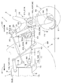
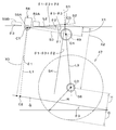
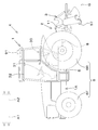
- FIG. 11 shows a working machine (agricultural working machine) 4 in which a tilling device 3 is connected to a connecting device 2 attached to a traveling vehicle 1.
- a tractor is exemplified as the traveling vehicle 1.
- the rotary tilling device is exemplified.
- the arrow A1 direction (forward direction of the working machine 4) in FIG. 11 will be described as forward
- the arrow A2 direction (reverse direction of the working machine 4) in FIG. 11 will be described as backward. Therefore, the front side of FIG. 11 is on the left side, and the back side of FIG. 11 is on the right side.
- the horizontal direction orthogonal to the front-rear direction will be described as the vehicle body width direction.
- the working machine 4 has a travelable vehicle body 1A.
- the vehicle body 1A has a prime mover (not shown) and a power transmission case (transmission device) 5.
- the prime mover is an engine such as a diesel engine.
- the prime mover may be an electric motor, or may be a hybrid type having a diesel engine and an electric motor.
- the power transmission case 5 is transmitted via, for example, a flywheel housing accommodating a flywheel, a clutch housing accommodating a clutch for intermittently transmitting the power of a prime mover transmitted via the flywheel, and a clutch. It is configured by directly connecting to a mission case that houses a power transmission case 5 that shifts power.
- the working machine 4 has a traveling device 6 that supports the vehicle body 1A so as to be travelable.
- the traveling device 6 is, for example, a wheel-type traveling device 6 having a front wheel 6F provided at the front portion of the vehicle body 1A and a rear wheel 6R provided at the rear portion of the vehicle body 1A.
- a PTO shaft 8 is provided on the back surface of the vehicle body 1A so as to project rearward.
- the PTO shaft 8 is an output shaft that takes out the power of the working machine 4 (the power of the prime mover) to the outside.
- a hydraulic device 9 is mounted on the rear portion of the vehicle body 1A.
- the hydraulic device 9 has a hydraulic cylinder inside, and has a left lift arm 10L and a right lift arm 10R that are driven by the hydraulic cylinder and swing up and down.
- the connecting device 2 for connecting the rotary tilling device 3 is attached to the rear part of the vehicle body 1A.
- the connecting device 2 has a link mechanism such as a three-point link mechanism 11 and a connecting frame 12.
- the three-point link mechanism 11 has a top link 13 and a first lower link 14L and a second lower link 14R.
- the top link 13 is arranged at the upper rear of the vehicle body 1A and at the center in the vehicle body width direction.
- the front part of the top link 13 is pivotally connected to the top link bracket 15 attached to the back surface of the vehicle body 1A.
- the first lower link 14L and the second lower link 14R are arranged side by side in the vehicle body width direction behind the lower part of the vehicle body 1A.
- the front portions of the lower links 14L and 14R are pivotally connected to the lower link bracket 16 fixed to the vehicle body 1A.
- the middle part of the first lower link 14L and the left lift arm 10L are connected by a left lift rod 60L.
- the middle part of the second lower link 14R and the right lift arm 10R are connected by a right lift rod 60R. Therefore, by driving the left lift arm 10L and the right lift arm 10R and swinging them up and down, the first lower link 14L and the second lower link 14R swing up and down.
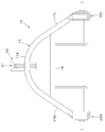
- the connecting frame 12 has a main frame 17.
- the main frame 17 is formed by bending a square pipe or the like.
- the upper portion 17A is formed in a curved shape that is convex upward when viewed from the front.
- the first side portion 17L extends diagonally downward to the left (inclination direction that shifts to the left as it goes downward) from the lower left end (lower end on one side) of the upper portion 17A.
- the second side portion 17R extends diagonally downward to the right (inclination direction that shifts to the right as it goes downward) from the lower right end (lower end on the other side) of the upper portion 17A.
- first side portion 17L and the second side portion 17R are extended from the main frame 17 so that the distance in the vehicle body width direction gradually increases toward the lower side.
- the upper portions of the first side portion 17L and the second side portion 17R are connected to each other by a reinforcing member 18 formed of a square pipe or the like.
- the upper engaging bracket 19 is fixed to the upper portion 17A of the main frame 17.
- the upper engaging bracket 19 has a link connecting portion 20 at the upper portion.
- the rear portion of the top link 13 is pivotally connected to the link connecting portion 20 (see FIG. 1A).
- the upper engaging bracket 19 has an engaging portion 21 at the rear portion.
- the engaging portion 21 includes a first engaging portion 21A and a second engaging portion 21B.
- the first engaging portion 21A and the second engaging portion 21B are formed in a hook shape, and the first engaging portion 21A is provided above the second engaging portion 21B.
- the first lower engaging bracket 22L is fixed to the lower end of the first side portion 17L
- the second lower engaging bracket 22R is fixed to the lower end of the second side portion 17R.
- the first lower link 14L is connected to the first lower engaging bracket 22L.
- a connecting pin or the like is fixed to the first lower engaging bracket 22L
- the rear portion of the first lower link 14L is pivotally connected to the connecting pin.
- the second lower link 14R is connected to the second lower engaging bracket 22R.
- a connecting pin or the like is fixed to the second lower engaging bracket 22R, and the rear portion of the second lower link 14R is pivotally connected to the connecting pin.
- the rotary tillage device 3 is exemplified as a side drive type rotary tillage device 3 in the present embodiment.
- the rotary tillage device 3 may be a center drive type rotary tillage device 3.
- the rotary tillage device 3 has a machine frame 46 and a tillage portion 47.
- the machine frame 46 includes a gear case 48 located in the center in the vehicle body width direction, a left support arm 49L extending to the left from the gear case 48, a right support arm 49R extending to the right from the gear case 48, and a left support arm 49L. It has a transmission case 50 attached to the right support arm 49R and a side frame attached to the right support arm 49R.
- the gear case 48 is provided with a PIC shaft (input shaft, not shown) so as to project forward.
- the PIC shaft is connected to the yoke 44 by spline coupling or the like, and the power from the PTO shaft 8 is transmitted via the drive shaft 40 through the bevel gear transmission mechanism in the gear case 48 and the transmission shaft in the left support arm 49L. It is transmitted to the chain transmission mechanism in the case 50.
- a top mast 54 is fixed to the upper part of the gear case 48.
- An upper connecting portion 55 that engages with the engaging portion 21 is provided on the front upper portion of the top mast 54.
- the upper connecting portion 55 is composed of pins, and in the illustrated example, the upper connecting portion 55 is fitted and engaged with the second engaging portion 21B.
- the bracket 51L is fixed to the left support arm 49L, and the bracket 51R is fixed to the right support arm 49R.
- the left bracket 51L is provided with a first lower connecting portion 52L
- the right bracket 51R is provided with a second lower connecting portion 52R.
- the first lower connecting portion 52L and the second lower connecting portion 52R are composed of pins.
- the left support arm 49L and the right support arm 49R may be collectively referred to as a support arm 49.
- the tilling portion 47 has a rotating shaft 56 provided between the lower part of the transmission case 50 and the side frame, and a large number of tilling claws 57 attached to the rotating shaft 56.
- the rotary shaft 56 is rotatably supported by the machine frame 46 around an axis extending in the width direction of the vehicle body.
- the rotation shaft 56 is rotated in the direction of arrow Y1 in FIG. 1A, for example, by the power transmitted to the chain transmission mechanism in the transmission case 50.
- the tilling claw 57 rotates together with the rotating shaft 56, plunges into the soil of the field, cultivates the soil, and releases the cultivated soil to the rear.
- the rotary tillage device 3 has a tillage cover including a main cover that covers the upper part of the tillage portion 47 and a rear cover that covers the rear of the tillage portion 47.
- the working machine 4 includes a control device 70 and a display device 80.
- the control device 70 and the display device 80 are connected by an in-vehicle network such as CAN.
- the control device 70 controls the traveling system and the working system of the working machine 4.
- the control device 70 may be any one that controls the work system and the traveling system of the work machine 4, and the control method is not limited.
- an operating member 72 is connected to the control device 70, and the control device 70 controls the raising and lowering of the connecting device 2 based on the operation of the operating member 72.
- an angle sensor 71 for detecting the angle of the lift arm 10 is connected to the control device 70, and the operating member 72 is a position lever 73 for operating the raising and lowering of the connecting device 2, and the connecting device 2.
- the control device 70 raises and lowers the control device 70 based on the detection signal output from the angle sensor 71, the operation signal output from the position lever 73, and the operation signal output from the upper limit setting dial 74.
- the control device 70 calculates (acquires) the angle (actual angle) of the lift arm 10 based on the detection signal output from the angle sensor 71 and a predetermined table stored in the storage device (not shown).
- the control device 70 calculates (acquires) the angle (indicated angle) of the lift arm 10 based on the operation of the position lever 73 based on the operation signal output from the position lever 73 and the predetermined table stored in the storage device. do.
- control device 70 has an upper limit (upper limit angle) of the angle of the lift arm 10 based on the operation of the upper limit setting dial 74 based on the operation signal output from the upper limit setting dial 74 and the predetermined table stored in the storage device. ), In other words, the upper limit of the height of the connecting device 2 is calculated (acquired).
- the control device 70 is the rear end of the lift arm 10 when the indicated angle is smaller than the upper limit angle and the actual angle is smaller than the indicated angle, or when the indicated angle is larger than the upper limit angle and the actual angle is smaller than the upper limit angle.
- the part (the end on the tilling device 3 side) is raised.
- the control device 70 maintains the height of the lift arm 10 when the indicated angle is smaller than the upper limit angle and the actual angle is equal to the indicated angle, or when the indicated angle is larger than the upper limit angle and the actual angle is equal to the upper limit angle. Let me.
- the control device 70 is the rear end of the lift arm 10 when the indicated angle is smaller than the upper limit angle and the actual angle is larger than the indicated angle, or when the indicated angle is larger than the upper limit angle and the actual angle is larger than the upper limit angle. Lower the part.
- the control device 70 may control the raising and lowering of the connecting device 2 based on the operation of the position lever 73, the upper limit setting dial 74, etc., and the control method is not limited to the above method, and existing technology can be applied. be.
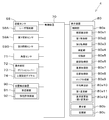
- the display device 80 can display various information about the work machine 4. Specifically, as shown in FIG. 2, the display device 80 includes a control unit 80a, a display unit 80b, and a storage unit 80c.
- the control unit 80a is composed of a CPU and the like, and mainly controls the display of the display unit 80b.
- the display unit 80b is a touch panel capable of displaying and inputting.
- the storage unit 80c is a non-volatile memory or the like, and stores information to be displayed on the display unit 80b, information related to control of the working machine 4, and the like.
- the storage unit 80c stores, for example, various application software (application software).
- the working machine 4 includes a position detection device 90.
- the position detection device 90 is a device that detects the position of the working machine 4 (vehicle body 1A).
- the position detection device 90 is, for example, a positioning device, and is provided in the traveling vehicle 1.
- the position detection device 90 can detect its own position (positioning information including latitude and longitude) by a satellite positioning system (positioning satellite) such as D-GPS, GPS, GLONASS, Hokuto, Galileo, and Michibiki.
- the position detection device 90 receives the satellite signal (position of the positioning satellite, transmission time, correction information, etc.) transmitted from the positioning satellite, and based on the satellite signal, the position of the working machine 4 (vehicle body 1A) (for example,). , Latitude, longitude), that is, the vehicle body position is detected.
- the position detection device 90 includes a receiving device 91 and an inertial measurement unit 92 (IMU: Inertial Measurement Unit) 92.
- the receiving device 91 is a device having an antenna or the like and receiving a satellite signal transmitted from a positioning satellite, and is attached to the vehicle body 1A separately from the inertial measurement unit 92.
- the receiving device 91 is attached to the upper part of the cabin (protection mechanism) 32 provided in the vehicle body 1A.
- the mounting position of the receiving device 91 is not limited to the above position, and may be the central portion of the bonnet, or may be the upper portion of the lops when the vehicle body 1A is provided with the lops.
- the inertial measurement unit 92 includes an acceleration sensor that detects the acceleration of the vehicle body 1A, a gyro sensor that detects the angular velocity of the vehicle body 1A, and the like.
- the inertial measurement unit 92 is provided below the vehicle body 1A, for example, the driver's seat 30, and can detect the roll angle, pitch angle, yaw angle, and the like of the vehicle body 1A.
- the position detection device 90 is a position detection device 90 that detects the position of the vehicle body 1A based on a satellite signal, but the position detection device 90 only needs to be able to detect the position of the vehicle body 1A.
- the position of the vehicle body 1A may be detected based on the acceleration detected by the inertial measurement unit 92 and the predetermined position information, and the configuration is not limited to the above. Further, the position detecting device 90 may be provided on the display device 80 instead of the traveling vehicle 1 as long as it can detect the position of the working machine 4, and the configuration thereof is not limited to the above configuration.
- the working machine 4 includes a distance sensor 58, a first inclination sensor 59A, and a tillage depth calculation unit 80a1.
- the distance sensor 58 is attached to the coupling device 2 and measures the distance to the ground G.
- the distance sensor 58 is a sensor that measures the distance from the distance sensor 58 to the ground G.
- the distance sensor 58 is composed of, for example, a laser sensor.
- the distance sensor 58 has a laser irradiation unit 58A, and measures the distance from the laser irradiation unit 58A to the ground G by receiving the laser light emitted from the laser irradiation unit 58A and reflected by the ground G.
- the distance sensor 58 is not limited to the laser sensor as long as it can measure the distance from the connecting device 2 to the ground G as shown in FIG. 3A.
- the distance sensor 58 is provided in the sensor mounting portion 62 mounted on the connecting frame 12.
- the sensor mounting portion 62 projects forward from the connecting frame 12 and protrudes forward from the tilling portion 47. Further, the distance sensor 58 is located behind the rear wheel 6R. Therefore, the distance sensor 58 measures the distance in the uncultivated land that is located in front of the cultivated portion 47 and is not cultivated by the cultivated portion 47.
- the distance sensor 58 may be attached to another portion of the connecting frame 12. Further, the distance sensor 58 may be attached to the first lower link 14L or the second lower link 14R, or may be attached to the first lower link 14L and the second lower link 14R.
- the first tilt sensor 59A is a sensor that detects the tilt of the rotary tillage device 3, and measures the tilt angle ⁇ 1 with respect to the horizontal (ground G). As shown in FIG. 1A, the first tilt sensor 59A is provided in the sensor mounting portion 62 like the distance sensor 58, and the first tilt sensor 59A is located behind the rear wheel 6R. The first tilt sensor 59A may be attached to another portion of the connecting frame 12 separately from the distance sensor 58.
- the tilling depth calculation unit 80a1 cultivates the tilling device 3 based on the inclination angle ⁇ 1 of the tilling device 3 with respect to the horizontal detected by the first inclination sensor 59A provided in the working machine 4, in addition to the distance measured by the distance sensor 58. Calculate the depth D.
- the tillage depth calculation unit 80a1 is composed of, for example, electrical / electronic parts, a program incorporated in the control unit 80a, and the like, and the tillage device 3 is cultivated based on the signals output from the distance sensor 58 and the first tilt sensor 59A. Calculate the depth D.
- the tillage depth calculation unit 80a1 acquires the distance measured by the distance sensor 58 and the inclination angle ⁇ 1 detected by the first inclination sensor 59A, and dimensional information used for calculating the tillage depth D in addition to the distance and the inclination angle ⁇ 1. Is obtained and the cultivation depth D is calculated.
- the calculation of the tillage depth D by the tillage depth calculation unit 80a1 will be described with reference to FIG. 3A.
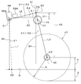
- FIG. 3A shows the reference (standard) working posture of the working machine 4, and shows the constituent parts of the rotary tilling device 3 and the position of the distance sensor 58 in the working posture in the working state.
- the radius of gyration of the cultivated claw 57 (the radius of the rotation locus of the outermost end of the cultivated claw 57 in the radial direction of rotation) is R, and the height of the axis C3 of the rotating shaft 56 from the ground G is H. .. Further, the line passing through the axis C3 and the axis C4 of the support arm 49 is defined as S1. Further, the tilt angle detected by the first tilt sensor 59A is ⁇ 1, and the mounting angle of the first tilt sensor 59A is ⁇ 2.
- the angle of the sensor 59A is ⁇ 2.
- the line passing through the irradiation starting point C1 and orthogonal to the line S1 is defined as S2, and the intersection of the line S1 and the line S2 is defined as C5.
- the line S3 shows a horizontal line
- the line S4 shows a vertical line.
- the distance L2 between the irradiation starting point C1 and the intersection C5 and the distance L3 between the axial center C3 and the intersection C5 are obtained based on the dimensions of the rotary tiller 3 and the position of the irradiation starting point C1.
- the distance L2 and the distance L3 are obtained, and the tillage depth calculation unit 80a1 acquires the dimensional information (distance L2, L3, mounting angle ⁇ 2) and the turning radius R from the outside in advance.
- the working machine 4 includes a first acquisition unit 80a2 and a second acquisition unit 80a3, and the first acquisition unit 80a2 and the second acquisition unit 80a3 are, for example, electric / electronic parts and a control unit 80a. It consists of built-in programs and the like.
- the first acquisition unit 80a2 acquires the individual information of the tilling device 3 connected to the connecting device 2.
- the first acquisition unit 80a2 acquires the individual information of the tilling device 3 by acquiring the information input to the display device 80 via the storage unit 80c or the like.
- the storage unit 80c stores individual information (identification information) that can be identified by the cultivating device 3, such as the name, model number, and product number of the cultivating device 3 that can be attached to the working machine 4, and the first acquisition unit 80a2 stores the individual information (identification information) that can be identified by the cultivating device 3.
- the individual information of the tilling device 3 is acquired from the storage unit 80c.
- the second acquisition unit 80a3 can acquire the turning radius R in addition to the distances L2 and L3 and the mounting angle ⁇ 2 of the first inclination sensor 59A as dimensional information.
- the display device 80 can display a predetermined setting screen M1 capable of setting and inputting the distances L2 and L3, the mounting angle ⁇ 2, and the turning radius R, and the second acquisition unit 80a3 inputs the information set and input to the setting screen M1. It can be obtained.
- the storage unit 80c stores the individual information of the tilling device 3 in association with the information set and input to the setting screen M1, and the second acquisition unit 80a3 sets and inputs to the setting screen M1 via the storage unit 80c and the like. Get the information that was done.
- the plowing depth calculation unit 80a1 obtains the plowing depth D by the following formula [1].
- D RH [1]
- the height H is calculated by the following formula [2].
- H X0 + X1-X2 [2]
- X0 is L1cos ⁇ 1, which is a value obtained by correcting the distance L1 measured by the distance sensor 58 to the vertical distance to the ground G.
- the plowing depth D is obtained by the following equation [3].
- D R- (L1cos ⁇ 1 + L2sin ( ⁇ 1 + ⁇ 2) -L3cos ( ⁇ 1 + ⁇ 2)) [3]
- the tillage depth calculation unit 80a1 calculates the tillage depth D by the equation [3] based on the distance L1 measured by the distance sensor 58 and the inclination angle ⁇ 1 detected by the first inclination sensor 59A.
- the tilling depth D is calculated by taking this inclination into consideration. Will be done. That is, the control device 70 corrects the distance L1 to the ground G measured by the distance sensor 58 by the inclination angle ⁇ 1 detected by the first inclination sensor 59A. As a result, the tillage depth D can be detected with high accuracy.
- the distance sensor 58 is not limited to one, and a plurality of distance sensors 58 may be provided. When a plurality of distance sensors 58 are provided, the plowing depth D is calculated with the average value of the distances measured by each distance sensor 58 as L1.
- the working machine 4 includes a second tilt sensor 59B, and the control device 70 has a correction unit 80a4 and a switching unit 80a5.
- the second tilt sensor 59B is a sensor that detects the tilt of the traveling vehicle 1 and measures the tilt angle ⁇ 3 with respect to the horizontal (ground G). Specifically, the second tilt sensor 59B can measure the pitch angle of the tilt of the vehicle body 1A. As shown in FIG.
- the second tilt sensor 59B is provided on the vehicle body 1A and can detect the inclination angle ⁇ 3 of the vehicle body 1A with respect to the horizontal.
- the second tilt sensor 59B only needs to be able to detect at least the tilt of the vehicle body 1A, and the mounting position and the structure of the sensor are not limited to the above-described configuration, and the inertial measurement unit 92 of the position detection device 90 is the first. 2
- the configuration may be such that the tilt sensor 59B is also used.
- the correction unit 80a4 and the switching unit 80a5 are composed of, for example, electrical / electronic components, a program incorporated in the control unit 80a, and the like.
- the correction unit 80a4 corrects the tillage depth D of the tillage device 3 calculated by the tillage depth calculation unit 80a1 based on the inclination angle ⁇ 3 of the traveling vehicle 1 detected by the second inclination sensor 59B, and corrects the area orthogonal to the ground G.
- the later tillage depth D (second tillage depth D2) can be calculated.
- the tillage depth D calculated by the tillage depth calculation unit 80a1 without the correction of the correction unit 80a4 is referred to as the first tillage depth D1
- the tillage depth calculation unit 80a1 is corrected by the correction unit 80a4.
- the calculated corrected tillage depth D may be referred to as a second tillage depth D2.
- control unit 80a has a mode in which correction by the correction unit 80a4 is allowed, that is, a first mode (slope mode) in which correction by the correction unit 80a4 is effective, and a mode in which correction by the correction unit 80a4 is prohibited, that is, correction. It is possible to switch to the second mode (flat ground mode) in which the correction by the unit 80a4 is invalid. That is, in the first mode, the tillage depth calculation unit 80a1 calculates the second tillage depth D2, and in the second mode, the tillage depth calculation unit 80a1 calculates the first tillage depth D1.
- the switching unit 80a5 switches the control unit 80a to either the first mode or the second mode.
- the switching unit 80a5 switches to either the first mode or the second mode based on the operation information input to the slope mode ON / OFF switching button 124 of the setting screen M1.
- the correction unit 80a4 detects the inclination angle ⁇ 1 in the calculation of the first tillage depth D1 in the second mode by the second inclination sensor 59B. The correction is made by, and the cultivation depth calculation unit 80a1 calculates the corrected second cultivation depth D2.
- the calculation of the second tillage depth D2 by the tillage depth calculation unit 80a1 corrected by the correction unit 80a4 will be described with reference to FIG. 3B.
- the second tillage depth D2 is obtained by the following equation [4] as described above.
- D2 RH'[4]
- the corrected height H' is calculated by the following equation [5].
- H' X'0 + X'1-X'2 [5]
- X0' is L1cos ⁇ '1, and is a value obtained by correcting the distance L1 measured by the distance sensor 58 to the vertical distance to the ground G.
- the depth calculation unit 80a1 calculates the tillage depth D based on the equation [3]. As a result, it is possible to accurately detect the cultivation depth D while suppressing the influence of disturbance due to the unevenness even when traveling in a field having relatively many irregularities and not sloped.
- the correction unit 80a4 corrects the inclination angle ⁇ 1 with the inclination angle ⁇ 3, and the tillage depth calculation unit 80a1 calculates the corrected second cultivation depth D2, but the correction unit 80a4 calculates the inclination angle. It suffices if the first tillage depth D1 of the tilling device 3 calculated by the tillage depth calculation unit 80a1 can be corrected based on ⁇ 3 to calculate the second tillage depth D2. May be configured to calculate the second tillage depth D2.
- the display device 80 of the working machine 4 includes a tillage depth acquisition unit 80a6, a reference acquisition unit 80a7, a position acquisition unit 80a8, a map creation unit 80a9, and an average calculation unit 80a10.
- the tillage depth acquisition unit 80a6, the reference acquisition unit 80a7, the position acquisition unit 80a8, the map creation unit 80a9, and the average calculation unit 80a10 are composed of, for example, electrical / electronic parts, a program incorporated in the control unit 80a, and the like.
- the tillage depth acquisition unit 80a6 acquires the tillage depth D (first tillage depth D1 or second tillage depth D2) of the tillage device 3 possessed by the working machine 4.
- the plowing depth D calculated by the plowing depth calculation unit 80a1 is acquired.
- the tillage depth acquisition unit 80a6 only needs to be able to acquire the tillage depth D of the tillage device 3, and the acquisition source is not limited to the tillage depth calculation unit 80a1, and the tillage depth acquisition unit 80a6 is calculated by, for example, the tillage depth calculation unit 80a1.
- the plowing depth D temporarily stored in the storage unit 80c may be acquired.
- the standard acquisition unit 80a7 acquires a predetermined standard indicating the degree of plowing depth D.
- the reference acquisition unit 80a7 acquires the information stored in the storage unit 80c in advance and the information set and input by operating the display unit 80b.
- the standard is a level (rank) indicating the degree of plowing depth D.
- the standard includes three levels, the first level, the second level, and the third level in the order of shallower tillage depth D. That is, the reference in the present embodiment corresponds to the tillage depth D and is the lower limit value which is the threshold value between the first level and the second level and the upper limit value which is the threshold value between the second level and the third level. Includes.
- the most appropriate value among the central level (second level in the present embodiment) among the standards will be described as the reference value. Further, a case where the lower limit value of the reference is "11.5 cm” and the upper limit value is “13.5 cm” will be described as an example.
- the level included in the standard may be four or five, and the number is not limited.
- the position acquisition unit 80a8 acquires the position of the working machine 4 when cultivated by the tilling device 3.
- the position acquisition unit 80a8 can acquire at least the position of the vehicle body 1A when cultivated by the tilling device 3 among the positions of the vehicle body 1A detected by the position detection device 90, and can acquire the current position of the vehicle body 1A.
- the map creation unit 80a9 associates the tillage depth D acquired by the tillage depth acquisition unit 80a6 with the reference acquired by the reference acquisition unit 80a7 and the position acquired by the position acquisition unit 80a8 to form a field map (first field map). Create m1).
- the first field map m1 is a field when the working machine 4 is actually driven, and is a virtual field in which the degree of tillage depth D acquired by the tillage depth acquisition unit 80a6 is associated with each position.
- the tillage depth D acquired by the tillage depth acquisition unit 80a6 is assigned.
- the area Qn is divided, for example, according to the time interval in which the plowing depth acquisition unit 80a6 acquires the plowing depth D.
- the area up to the position acquired by the position acquisition unit 80a8 when the tillage depth D is acquired is classified as one area Qn.
- the width of the area Qn corresponds to the length (working width) in the width direction of the tilling device 3.
- the first field map m1 includes the tillage depth D acquired by the tillage depth acquisition unit 80a6, the reference acquired by the reference acquisition unit 80a7, and the position acquired by the position acquisition unit 80a8.
- the first field map m1 whose creation is completed by the map creation unit 80a9 is stored in the storage unit 80c.
- the first field map m1 being created by the map creation unit 80a9 is temporarily stored in the storage unit 80c, and is updated every time the tillage depth acquisition unit 80a6 acquires the tillage depth D. Further, when the work machine 4 finishes the work of acquiring the plowing depth D, the map creation unit 80a9 finishes the update of the first field map m1, that is, the temporary storage in the storage unit 80c, and completes the creation.
- the generated first field map m1 is stored in the storage unit 80c.
- the tillage depth calculation unit 80a1 calculates the tillage depth D at the position where the work machine 4 has traveled, that is, the position where the tillage device 3 has passed, the first field map m1 is on the route where the work machine 4 has traveled. Will be created. For example, when the working machine 4 performs the tilling work by the tilling device 3, the working machine 4 travels substantially linearly from one side to the other side and from the other side to one side of the field, so that the plurality of areas Qn are in the field. A plurality of areas Qn extending from one side to the other and continuous in a band shape are displayed so as to be parallel to each other.
- the area Qn is divided according to the time interval in which the tillage depth acquisition unit 80a6 acquires the tillage depth D, but the map creation unit 80a9 sets the area Qn to a predetermined distance regardless of the time interval. It may be divided into intervals (positional intervals), or it may be divided into meshes of predetermined intervals, and the method of dividing the area Qn is not limited to the above-mentioned method.
- the map creation unit 80a9 associates the tillage depth D acquired by the tillage depth acquisition unit 80a6 with the reference acquired by the reference acquisition unit 80a7 and the position acquired by the position acquisition unit 80a8 to form a field map (first field). Map) m1 may be created, and the field map m1 may display the tillage depth D as contour lines, and the display method thereof is not limited to the above-mentioned method.
- the average calculation unit 80a10 calculates the average of the tillage depth D based on the tillage depth D acquired by the tillage depth acquisition unit 80a6.
- the average calculation unit 80a10 acquires a plurality of plowing depths D included in the first field map m1 and averages the plurality of plowing depths D to obtain the plowing depths in the first field map m1. Calculate the average of D.
- the storage unit 80c stores the first field map m1 and the average of the tillage depth D corresponding to the first field map m1 and calculated by the average calculation unit 80a10 in association with each other.
- the first field map m1 includes the plowing depth D acquired by the plowing depth acquisition unit 80a6, the reference acquired by the reference acquisition unit 80a7, the position acquired by the position acquisition unit 80a8, and the average calculation unit 80a10.
- Date information (year / month / day or year / month), time information (start time and / or end time of tillage), total tillage time, average value of tillage depth D, running speed of work machine 4, work width,
- the model of the working machine 4 and any or all of the reference values may be included.
- the display unit 80b of the display device 80 can display various screens (plurality of screens) in response to operations, for example, a predetermined home screen (not shown).
- the setting screen M1, the first application screen M2 for displaying the tillage depth D of the tilling device 3, the first reference screen M3 for accepting the reference setting input, and the like are individually displayed.
- a common designated unit 110 is displayed on the screen displayed by the display unit 80b.
- the designation unit 110 specifies the transition of the screen displayed by the display unit 80b, and can switch the screens displayed by the display unit 80b to each other.
- the designation unit 110 has, for example, a home button 110a for designating the display of the home screen (switching to the home screen) and a return button 110b for returning to the previous screen (switching to the previous screen) from the currently displayed screen. And include. Further, when the first application screen M2 or the like is displayed, the designation unit 110 has a setting button 110c for designating the display of the setting screen M1. The setting button 110c is arranged on the opposite side of the home button 110a and the return button 110b.
- the setting screen M1 is a screen for controlling the work machine 4 and setting the display device 80, and the display unit 80b displays the setting screen M1 when the setting button 110c of the designated unit 110 is operated. As shown in FIG. 4, the setting screen M1 displays a plurality of setting areas corresponding to the contents to be set. In the present embodiment, the setting screen M1 displays a first setting area 120a, a second setting area 120b, a third setting area 120c, a fourth setting area 120d, and a fifth setting area 120e.
- the first setting area 120a is an area on the left side of the setting screen M1 and displayed above the designated area 115.
- the first setting area 120a is an area for setting and inputting information about the tilling device 3.
- the second setting area 120b is an area displayed on the upper right side of the setting screen M1.
- the second setting area 120b is, for example, an area for setting and inputting information regarding the setting of the first application screen M2.
- the third setting area 120c is an area displayed on the lower right side of the setting screen M1.
- the third setting area 120c is, for example, an area for setting and inputting information related to communication of the position detection device 90.
- the fourth setting area 120d is an area displayed below the third setting area 120c, and includes a first confirmation button 121 for confirming the information set and input in the first setting area 120a to the third setting area 120c. I'm out.
- the fifth setting area 120e is an area on the left side of the setting screen M1 and displayed between the first setting area 120a and the designated area 115.
- the fifth setting area 120e includes a work history button 123 for displaying the setting screen M1 described later, and a slope mode ON / OFF switching button 124.
- the first setting area 120a is an area in which information related to the calculation of the tillage depth D of the tilling device 3, that is, individual information of the tilling device 3, dimensional information of the distance sensor 58 and the first inclination sensor 59A, and the like can be set and input. .. Specifically, as shown in FIG. 4, the first setting area 120a displays a plurality of input units 122. The plurality of input units 122 can set and input individual information of the tilling device 3 and dimensional information of the first tilt sensor 59A.
- the plurality of input units 122 are a first input unit 122a which is a part for inputting at least a turning radius R, a second input unit 122b which is a part for inputting a distance L2, and a third input which is a part for inputting a distance L3.
- the unit 122c includes a fourth input unit 122d, which is a portion for inputting the mounting angle ⁇ 2 of the first tilt sensor 59A, and a device selection unit 122e for selecting individual information of the tilling device 3.
- the first input unit 122a to the fourth input unit 122d can accept the input of arbitrary numerical values, and the input of the numerical values to the first input unit 122a to the fourth input unit 122d is a predetermined display on the display unit 80b. This is performed by operating the operation tool of the above, the operation switch of the display device 80, and the like.
- the device selection unit 122e is a part for selecting and operating individual information of the tilling device 3 connected to the connecting device 2, that is, selecting and operating individual information that can be identified by the tilling device 3, such as the name, model number, and product number of the tilling device 3. be.
- the device selection unit 122e displays, for example, individual information acquired from the storage device by the control unit 80a as a list, and the operator operates the display unit 80b or operates an operation switch or the like of the display device 80. Select individual information.
- the setting screen M1 displays the device selection unit 122e capable of selecting and operating the individual information of the tilling device 3, but the setting screen M1 only needs to be able to input the individual information and displays it on the display unit 80b.
- a portion where individual information of the tilling device 3 is directly input may be displayed by operating a predetermined operating tool, an operation switch of the display device 80, or the like.
- the storage unit 80c receives individual information of the tilling device 3 selected by the device selection unit 122e, the first input unit 122a.
- the ⁇ 2 is associated and stored.
- the plurality of input units 122 have a length (working width) in the width direction of the tilling device 3 and a working range of the tilling device 3 separately from the device selection unit 122e and the first input unit 122a to the fourth input unit 122d. It may include an input unit for inputting a width (wrap width) to be wrapped (overlap). Further, the display device 80 obtains the turning radius R, the distance L2, the distance L3, and the mounting angle ⁇ 2 corresponding to the individual information from the storage unit 80c based on the individual information of the tilling device 3 selected by the device selection unit 122e. It may be acquired and displayed in advance on the first input unit 122a to the fourth input unit 122d, and the display of the setting screen M1 is not limited to the above-described configuration.
- the setting screen M1 only needs to be able to set and input information related to the calculation of the tilling depth D of the tilling device 3, that is, individual information of the tilling device 3, and dimensional information of the distance sensor 58 and the first tilt sensor 59A, and display the information thereof.
- the area, display method, and the like are not limited to the above configuration.
- the first application screen M2 is a screen for displaying various information corresponding to the application, and has the first application area 130.
- the first application area 130 is displayed above the designated area 115.
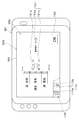
- 5A shows a screen for displaying the first field map m1 being created by the map creation unit 80a9 among the cultivation depth display applications for displaying the cultivation depth D of the tillage device 3.
- the first application screen M2 based on the tillage depth D acquired by the tillage depth acquisition unit 80a6 of the display device 80, the tillage depth D of the tillage depth D performed by the tillage device 3 by actually running the working machine 4 Can be displayed.
- the first application area 130 of the first application screen M2 is mainly divided into a first display area 130a, a second display area 130b, and a third display area 130c.
- the first display area 130a is an area displayed from the left end to the right end of the first application area 130, for example, at the upper end of the first application area 130.
- the current tillage depth D acquired by the tillage depth acquisition unit 80a6 is displayed. Further, when the current tillage depth D is equal to the reference value acquired by the reference acquisition unit 80a7, "reference tillage depth" is displayed in the vicinity of the displayed tillage depth D.
- predetermined information such as the position information of the working machine 4 and the vehicle speed may be displayed in the first display area 130a.
- the mileage of the working machine 4 the mileage of the cultivating device 3 (the product of the working width and the mileage), the positioning state of the position detecting device 90, and the like are displayed. It may be displayed.
- the second display area 130b is displayed below the first display area 130a, and is an area extending from the left end of the first application area 130 to the right side. That is, the second display area 130b is arranged between the designated area 115 and the first display area 130a.
- the third display area 130c is arranged on the right side of the second display area 130b, and is an area displayed between the designated area 115 and the first display area 130a at the right end of the first application area 130.
- the second display area 130b displays the field display unit 131
- the field display unit 131 displays the first field map m1 created by the map creation unit 80a9.
- the field display unit 131 includes a case where the driver seated in the driver's seat 30 of the work machine 4 (vehicle body 1A) sees an actual field and a first field map m1 (field image) displayed on the field display unit 131.
- the field image is displayed diagonally so that and is sensuously matched.
- the field image displayed by the field display unit 131 may be a bird's-eye view display, and the display form thereof is not limited to the above-mentioned form.
- the virtual field displayed on the field display unit 131 may be referred to as a "virtual field" or a "field image”.
- the field display unit 131 displays the current position of the working machine 4 acquired by the position acquisition unit 80a8.
- the field display unit 131 shows a machine display unit 132 that displays the position of the working machine 4 based on the position information acquired by the position acquisition unit 80a8, that is, the position information detected by the position detection device 90. ing. More specifically, it is an image unit that displays the current position of the working machine 4 on the field display unit 131, and the machine display unit 132 virtually shows the working machine 4 (vehicle body 1A).
- the machine display unit 132 has a fixed display position of the machine display unit 132 with respect to the field display unit 131.
- the virtual field (field image) shown in 131 scrolls.
- the field display unit 131 displays the divided data d2n assigned to the plurality of areas Qn in different display modes according to the degree.
- the field display unit 131 displays the first degree display unit 141 showing the divided data d2n on the field image.
- the first degree display unit 141 is displayed on the field display unit 131 and displays the degree of tillage depth D with respect to a predetermined reference at a predetermined position.
- the first degree display unit 141 displays the degree of tillage depth D in each area Qn on the field in sections having different display forms based on the first field map m1.
- the first degree display unit 141 "reds" an area Qn (first level) in which the tillage depth D is less than the lower limit value, that is, an area Qn in which the tillage depth D is relatively shallow, in the virtual field displayed by the field display unit 131. It is displayed in the section 142a of. Further, the first degree display unit 141 sets the area Qn (second level) in which the plowing depth D is equal to or greater than the lower limit value and equal to or less than the upper limit value, that is, the area Qn in which the plowing depth D is appropriate, to be "blue" in the virtual field.
- the area Qn in which the tillage depth D exceeds the upper limit value, that is, the area Qn (third level) in which the tillage depth D is relatively deep is displayed in the section 142b, and is displayed in the “yellow” section 142c.
- the first degree display unit 141 may display the degree of the first field map m1 by changing the display form according to the degree, and the display form to be different is not limited to the color, and the different colors are described above. It is not limited to the color gamut, and the operator may change it arbitrarily.
- the first degree display unit 141 may display the section 142a in "light blue”, the section 142b in “green”, and the section 142c in “red”, and is not limited to the above-described configuration. ..
- the display unit 80b may display the tillage depth D of the current tillage device 3 separately from the first field map m1 of the field display unit 131. Specifically, the display unit 80b displays the second degree display unit 145 on the first application screen M2. The second degree display unit 145 displays the degree of tillage depth D with respect to a predetermined reference at the place where the tillage device 3 is located. Specifically, the second degree display unit 145 determines the degree of tillage depth D at the current position of the working machine 4 from the displayed first field map m1 based on the position information acquired by the position acquisition unit 80a8. indicate. Further, the second degree display unit 145 is displayed in the third display area 130c.
- the second degree display unit 145 has a numerical display unit 146, a first display unit 148, and a second display unit 149.
- the numerical display unit 146 is a part that displays the tillage depth D acquired by the tillage depth acquisition unit 80a6 as a numerical value or the like.
- the first display unit 148 indicates, for example, that the tillage depth D is shallower than the reference, that is, that the tillage depth D acquired by the tillage depth acquisition unit 80a6 is less than the lower limit value with an arrow pointing in one direction (for example, upward).
- the figure is shown and is arranged above the numerical display unit 146 as shown in FIG. 5A.
- the second display unit 149 indicates that, for example, the tillage depth D is deeper than the reference, that is, the tillage depth D acquired by the tillage depth acquisition unit 80a6 exceeds the upper limit value, which is opposite to one direction. It is a figure indicated by an arrow pointing in a direction (for example, downward), and is arranged below the numerical display unit 146.
- a window for accepting a selection input as to whether or not to return to the home screen is displayed in a pop-up (not shown).
- the map creation unit 80a9 ends the creation of the first field map m1 being created, and the storage unit 80c finishes the creation of the first field.
- the storage unit 80c stores the first field map m1 for which the creation is completed, the average calculation unit 80a10 calculates the average value of the tillage depth D.
- the storage unit 80c stores the updated first field map m1 in association with the average value of the corresponding tillage depth D.
- the storage unit 80c stores the first field map m1 and the average value of the tillage depth D in association with each other, and when a predetermined operation is performed on the display device 80 to display the first application screen M2 again, FIG. 5B is shown.
- the selection operation unit in the present embodiment, the first selection reception unit 135 and the second selection reception unit 136) is displayed in the first application area 130.
- the selection operation units 135 and 136 can accept the first operation and the second operation.
- the first selection reception unit 135 can accept the first operation
- the second selection reception unit 136 can accept the second operation.
- the first selection reception unit 135 and the second selection reception unit 136 are image units capable of selecting either one, and the first selection reception unit 135 is described as “from the beginning”, and the second selection reception unit 135 is described as “from the beginning”. 136 is written as "work from the continuation”.
- the map creation unit 80a9 When the selection operation units 135 and 136 accept the first operation, the map creation unit 80a9 newly creates the first field map m1, and when the selection operation units 135 and 136 accept the second operation, the map creation unit The 80a9 updates the first field map m1 stored in the storage unit 80c. Specifically, when the first selection reception unit 135 accepts the first operation, the map creation unit 80a9 is a first field map different from the first field map m1 for which the previous creation was completed, based on the operation information. Start creating the field map m1.
- the map creation unit 80a9 acquires the first field map m1 for which the previous creation was completed from the storage unit 80c based on the operation information, and acquires the first field map m1. The creation of the first field map m1 is resumed, and the first field map m1 is updated.
- the selection operation unit includes the first selection reception unit 135 and the second selection reception unit 136, but the selection operation unit is a first field map different from the first field map m1 whose creation was completed last time. It suffices if the selection operation of starting the creation of m1 or restarting the creation of the first field map m1 can be accepted, and the configuration is not limited to the above-mentioned configuration. Further, the map creation unit 80a9 may be able to determine the first field map m1 being created based on some operation or input information. For example, the first application screen M2 may be displayed by the working machine 4. It may have a save button (not shown) for ending cultivation, that is, confirming the first field map m1 created by the map creation unit 80a9.
- the map creation unit 80a9 ends the creation of the first field map m1 being created, and the storage unit 80c stores the first field map m1 that has been created. .. Further, when the save button is operated and the storage unit 80c stores the first field map m1 whose creation has been completed, the average calculation unit 80a10 calculates the average value of the tillage depth D.
- the display device 80 includes a first change unit 80a11.
- the first change unit 80a11 is composed of, for example, electrical / electronic parts, a program incorporated in the control unit 80a, and the like, and the first change unit 80a11 inputs the changed reference to the screen displayed on the display unit 80b.
- the first reception unit 150 that accepts the above is displayed, and the standard is changed based on the information input to the first reception unit 150.
- the standard acquisition unit 80a7 acquires the changed standard
- the map creation unit 80a9 associates the changed standard with the first field map m1 being created.
- the map creation unit 80a9 reassigns the division data d2n based on the division data d1n included in the first field map m1 and the reference acquired by the reference acquisition unit 80a7, so that the first field map m1 To update.
- the first reception unit 150 is displayed on the first reference screen M3 displayed by the display unit 80b.
- the display device 80 is displayed on the display unit 80b as shown in FIG. 1 Display the reference screen M3.
- the first reception unit 150 has a reference input unit 151 and a second confirmation button 152.
- the reference input unit 151 is a portion that can accept a reference input for the tillage depth D, and is a portion that defines a range in which the tillage depth D is “appropriate”.
- the reference input unit 151 includes a reference value input unit 151a, a lower limit input unit 151b, and an upper limit input unit 151c.
- the reference value input unit 151a is a portion for inputting the most appropriate value of the tillage depth D, and in FIG. 6, "12.5 cm" is input as the reference value.
- the lower limit input unit 151b is a part of the standard for inputting the lower limit value corresponding to the tillage depth D.
- the lower limit input unit 151b accepts the input of the lower limit value by receiving the input of the difference between the reference value and the lower limit value (first deviation), and in FIG. 6, the lower limit input unit 151b is set to " "1.0 cm” is input. That is, in the first reception unit 150 shown in FIG. 6, the lower limit value is input as "11.5 cm".
- the upper limit input unit 151c is a part of the standard for inputting the upper limit value corresponding to the tillage depth D.
- the upper limit input unit 151c accepts the input of the upper limit value by receiving the input of the difference (second deviation) between the reference value and the upper limit value, and in FIG. 6, the upper limit input unit 151c is set to ". "1.0 cm” is input. That is, in the first reception unit 150 shown in FIG. 6, the upper limit value is input as "13.5 cm".
- the second confirmation button 152 is an image unit capable of confirming a value (reference value or the like) input by the reference input unit 151. Therefore, when the operator sets and inputs a value to the reference input unit 151 and operates the second confirmation button 152, the reference acquisition unit 80a7 acquires the input reference value, the first deviation, and the second deviation. , The map creation unit 80a9 associates the reference value, the first deviation, and the reference based on the second deviation with the first field map m1 displayed by the field display unit 131, and the division included in the first field map m1. The divided data d2n is reassigned based on the data d1n and the reference acquired by the reference acquisition unit 80a7, and the first field map m1 is updated.
- the display device 80 can call and display the field map (first field map m1) stored in the storage unit 80c.
- the display device 80 includes a list display unit 160, selection units 161, 166, and a map display unit 171.
- the list display unit 160, the selection units 161, 166, and the map display unit 171 are display images displayed on various screens displayed on the display device 80.
- the list display unit 160 displays the first field map m1 stored in the storage unit 80c as a list.
- the selection unit accepts a selection operation of one of the first field maps m1 displayed on the list display unit 160.
- the map display unit 171 calls and displays the first field map m1 for which the selection unit has received the selection operation from the storage unit 80c.
- the control unit 80a performs an arithmetic process for displaying the list display unit 160, the selection unit, and the map display unit 171 on the display unit 80b.
- the list display unit 160, the selection unit, and the map display unit 171 will be described in detail mainly with reference to FIGS. 7A to 8.
- the display unit 80b individually displays the list display unit 160, the list screen M4 for displaying the selection units 161, 166, and the second application screen M6 for displaying the map display unit 171. Further, on the list screen M4 and the detail screen M5, the designated unit 110 common to the screens M1, M2, and M3 is displayed.
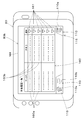
- the display device 80 displays the list screen M4 on the display unit 80b as shown in FIG. 7A.
- the list screen M4 is a screen for displaying a list of information of the first field map m1 stored in the storage unit 80c, and has a list display unit 160.
- the list display unit 160 is displayed above the designated area 115.
- the list display unit 160 displays a list of the first field map m1 stored in the storage unit 80c as a table.
- the list display unit 160 has a name display unit 160a for displaying the name of the tilling work corresponding to the first field map m1 and a date for displaying the date information on which the working machine 4 has cultivated. It has a display unit 160b and.
- the list screen M4 may have a selection unit 161 in addition to the list display unit 160.
- the selection unit 161 is displayed on the right side of the table of the list display unit 160.
- the selection unit 161 is arranged adjacent to the list display unit 160, and is a plurality of image units corresponding to each of the first field map m1 displayed by the table. That is, in the present embodiment, when the selection unit 161 adjacent to the right side of the first field map m1 of the first field map m1 displayed on the list display unit 160 is selected, the selection unit is selected. 161 accepts the selection input of the first field map m1.
- the selection unit 161 is arranged adjacent to the list display unit 160, but the display device 80 may have the list display unit 160 and the selection units 161, 166.
- the display method and display form thereof are not limited to the above-mentioned examples, and may be configured such that the image unit of the selection unit 161 is displayed in the table of the list display unit 160, for example.
- the selection unit 166 may be displayed on a screen different from the list display unit 160, that is, may be displayed on a screen different from the list screen M4.
- the display unit 80b may be capable of displaying the selection unit 166 and the detail screen M5 displaying the details of the first field map m1.
- the detail screen M5 is a screen that transitions from the list screen M4, and is one of the first field maps m1 displayed on the list display unit 160, for example, by operating the list display unit 160.
- the first field map m1 of is selected as the target of detailed display.
- the display unit 80b displays the detail screen M5 corresponding to the selected first field map m1.
- the detail screen M5 displays the information display unit 165 and the selection unit 166 above the designated area 115.
- the information display unit 165 is a display area for displaying information stored in the storage unit 80c in association with the first field map m1.
- the information display unit 165 may, for example, indicate the name of the tilling work corresponding to the first field map m1, the date information (year / month / day or year / month) in which the working machine 4 cultivated, the time information (the start time of tilling and the start time of tilling). / Or end time), total tillage time, average value of tillage depth D, running speed of work machine 4, work width, model of work machine 4, and any or all of reference values are displayed.
- the information display unit 165 is, for example, the name of the tilling work corresponding to the first field map m1, the date when the working machine 4 cultivated, the start time and the end time of the tillage, the total tillage time, and the tillage.
- the average value of the depth D, the traveling speed of the working machine 4, the working width, the model of the working machine 4, and the reference value are displayed.
- the average calculation unit 80a10 calculates the average value of the tillage depth D when the storage unit 80c stores the first field map m1 for which the creation is completed, and the information display unit 165 calculates the tillage depth.
- the average value of D is displayed, but the display device 80 only needs to be able to display the average value of the tillage depth D on at least the information display unit 165, and the timing at which the average calculation unit 80a10 calculates the average value of the tillage depth D is
- the storage unit 80c is not limited to storing the first field map m1.
- the average calculation unit 80a10 may use the first field map m1 displayed on the list display unit 160 when the first field map m1 is selected as the target for detailed display. It may be configured to calculate the average value of the tillage depth D in.
- the selection unit 166 displayed on the detail screen M5 accepts the selection input of the first field map m1 displayed on the detail screen M5, that is, among the first field map m1 displayed on the list display unit 160. Accepts the selection input of the first field map m1.
- the selection unit 166 displayed on the detail screen M5 is a display image displayed on the lower side of the information display unit 165.
- the information of the first field map m1 stored in the storage unit 80c may be editable. For example, among the information associated with the first field map m1, the first field map m1 is editable. The name of the cultivation work corresponding to the field map m1 and the description (memo) of the first field map m1 may be editable. Further, on the detail screen M5, the information of the first field map m1 stored in the storage unit 80c may be deleted. As shown in FIG. 7B, the detail screen M5 has a delete button 167, and the delete button 167 accepts an input operation for deleting data corresponding to the first field map m1 displayed on the detail screen M5. .. When the delete button 167 is operated, the control unit 80a deletes the data of the first field map m1 displayed on the detail screen M5 for which the delete button 167 has received the input operation from the storage unit 80c.
- the second application screen M6 is a screen that displays various information corresponding to the application like the first application screen M2, and has a second application area 170.
- the second application area 170 is displayed above the designated area 115.
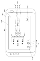
- the second application screen M6 of FIG. 8 shows a screen for displaying a field map stored in the storage unit 80c among the cultivation depth display applications for displaying the cultivation depth D of the tillage device 3.
- the second application area 170 of the second application screen M6 has a map display unit 171.
- the map display unit 171 displays, for example, the first field map m1 stored in the storage unit 80c and the selection units 161, 166 have received the selection input as a field map. Further, the map display unit 171 displays a bird's-eye view of the map image of the first field map m1 from above (bird's-eye view display). Similar to the field display unit 131, the map display unit 171 diagonally tilts the map image so that the driver seated in the driver's seat 30 of the work machine 4 (vehicle body 1A) sensuously matches the actual field.
- the display form may be limited to the above-mentioned form.
- the virtual field map displayed on the map display unit 171 may be referred to as a "virtual map" or a "map image".
- the map display unit 171 may be capable of enlarging or reducing the map image to be displayed, moving the area to be displayed, or performing a predetermined operation, and the display method is not limited to the above-described configuration.
- the map display unit 171 displays the divided data d2n assigned to the plurality of areas Qn of the first field map m1 in different display modes according to the degree.
- the map display unit 171 displays a third degree display unit 172 showing the divided data d2n on the map image.
- the third degree display unit 172 is displayed on the map display unit 171 and displays the degree of tillage depth D with respect to a predetermined reference at a predetermined position.
- the third degree display unit 172 displays the degree of plowing depth D at each position on the virtual map based on the first field map m1.
- the third degree display unit 172 "reds" the area Qn (first level) in which the plowing depth D is less than the lower limit value, that is, the area Qn (first level) in which the plowing depth D is relatively shallow, on the virtual map displayed by the map display unit 171. It is displayed in the section 173a of. Further, the third degree display unit 172 sets the area Qn (second level) in which the tillage depth D is equal to or less than the lower limit value and the upper limit value or less, that is, the area Qn (second level) in which the tillage depth D is appropriate, to be “blue” on the virtual map.
- the area Qn in which the tillage depth D exceeds the upper limit value, that is, the area Qn (third level) in which the tillage depth D is relatively deep is displayed in the section 173b, and is displayed in the “yellow” section 173c.
- the third degree display unit 172 may display the degree of the field map by changing the display form according to the degree, and the different display form is not limited to the color, and the different color is the color gamut described above. It is not limited to, and the worker may change it arbitrarily.
- the section 173a may be displayed in "light blue”
- the section 173b may be displayed in "green”
- the section 173c may be displayed in "red”
- the configuration is not limited to the above.
- the map display unit 171 may display the reference of the field map stored in the storage unit 80c. As shown in FIG. 8, a reference display unit 174 for displaying a reference is displayed on the left side of the third degree display unit 172.
- the reference display unit 174 displays the numerical values of the reference value, the lower limit value, and the upper limit value of the degree of the field map, and the color of the degree. By displaying the reference display unit 174, the correspondence between the color of the field map and the plowing depth value can be linked at a glance.
- the display device 80 of the working machine 4 includes a reference changing unit (second changing unit) 80a12 for changing the reference, and the map creating unit 80a9 is stored in the storage unit 80c.
- the first field map m1 is called, and a new field map (second field map m2) is created based on the change of the standard by the standard change unit 80a12.
- the map creation unit 80a9 calls the first field map m1 displayed on the map display unit 171 and creates a new field map (second field map m2) based on the change of the standard by the standard change unit 80a12. ..
- the reference changing unit 80a12 is composed of, for example, electrical / electronic parts, a program incorporated in the control unit 80a, and the like, and the reference changing unit 80a12 accepts the input of the changed standard on the screen displayed on the display unit 80b.
- the change input unit 180 is displayed, and the standard is changed based on the information input to the change input unit 180.
- the change input unit 180 is displayed on the second reference screen M7 displayed by the display unit 80b.
- the change input unit 180 has a reference input unit 181 and a third confirmation button 182.
- the reference input unit 181 is a portion that can accept a reference input to the tillage depth D, like the reference input unit 181, and is a portion that defines a range in which the tillage depth D is “appropriate”.
- the reference input unit 181 includes a reference value input unit 181a, a lower limit input unit 181b, and an upper limit input unit 181c.
- the reference value corresponding to the first field map m1 for which the selection units 161 and 166 have received the selection input is input in advance in the same manner as the reference value input unit 151a of the first reference screen M3, for example. "12.5 cm" is entered.
- the lower limit input unit 181b is a portion of the standard for inputting the lower limit value corresponding to the tillage depth D, similarly to the lower limit input unit 151b of the first reference screen M3.
- the input of the lower limit value is accepted by accepting the input of the difference between the reference value and the lower limit value (first deviation), and in the lower limit input unit 181b, the selection units 161 and 166 receive the selection input.
- the first deviation corresponding to one field map m1 is input in advance.
- "12.5 cm” is input to the reference value input unit 181a.
- "1.0 cm” is input in advance to the lower limit input unit 181b, and the case where the lower limit input unit 181b is changed to "2.0 cm” is shown. That is, in the change input unit 180 shown in FIG. 9, the lower limit value is input as "10.5 cm".
- the upper limit input unit 181c is a portion of the standard for inputting the upper limit value corresponding to the tillage depth D, similarly to the upper limit input unit 181c of the first reference screen M3.
- the input of the upper limit value is accepted by accepting the input of the difference (second deviation) between the reference value and the upper limit value, and in the upper limit input unit 181c, the selection units 161 and 166 receive the selection input.
- the second deviation corresponding to one field map m1 is input in advance.
- "1.0 cm” is input in advance in the upper limit input unit 181c, and the case where the upper limit input unit 181c is changed to "2.0 cm” is shown. That is, in the change input unit 180 shown in FIG. 9, the upper limit value is input as "14.5 cm".
- the third confirmation button 182 is an image unit capable of confirming a value (reference value, etc.) input by the reference input unit 181. Therefore, when the operator sets and inputs a value to the reference input unit 181 and operates the third confirmation button 182, the reference acquisition unit 80a7 acquires the input reference value, the first deviation, and the second deviation. , Divided data based on the divided data d1n included in the first field map m1 and the reference acquired by the reference acquisition unit 80a7 based on the first field map m1 in which the selection units 161, 166 have received the selection input. A new field map (second field map m2) is created by reassigning d2n, that is, associating the changed reference with the position and tillage depth D associated with the called first field map m1. create.
- the map display unit 171 displays the second field map m2 which is the new field map. Specifically, as shown in FIG. 10, the map display unit 171 displays the second field map m2 in place of the first field map m1. Therefore, the criteria are different between the first field map m1 and the second field map m2, and in the example of FIG. 9, the range in which the tillage depth D is appropriate (the range of the second level) is larger than that of the first field map m1. However, since the second field map m2 is larger, the degree of plowing depth D at each position on the map is displayed differently. Specifically, the second field map m2 displayed on the second application screen M6 shown in FIG.
- the reference changing unit 80a12 changes the reference, so that the map display unit 171 can shift the display from the first field map m1 to the second field map m2 having a different degree of tillage.
- the map display unit 171 shifts the display from the first field map m1 to the second field map m2, but the map creation unit 80a9 has the selection units 161, 166 accepting and storing the selection input.
- the first field map m1 stored in the unit 80c may be called to create a new field map (second field map m2) based on the change of the standard by the reference changing unit 80a12, and the map display unit 171 may store the map.
- the configuration may be such that the first field map m1 called from the unit 80c is not displayed, but the second field map m2 created by the map creation unit 80a9 is displayed.
- the map creating unit 80a9 changes to the changed reference, the first field map m1. It is possible to create a new second field map m2 different from the second field map m2 displayed by the map display unit 171 based on the associated position and cultivation.
- the display device 80 of the working machine 4 described above has a tilling depth acquisition unit 80a6 for acquiring the tilling depth D of the tilling device 3 possessed by the working machine 4, and a reference for acquiring a predetermined standard indicating the degree of the tilling depth D.
- the map creation unit 80a9 that creates the field map m1 by associating the position acquired by the position acquisition unit 80a8, the storage unit 80c that stores the field map m1 created by the map creation unit 80a9, and the storage unit 80c. It is provided with a map display unit 171 that calls and displays the field map m1. According to the above configuration, the work plan of the tilling device 3 can be easily created by displaying the field map m1 stored in the storage unit 80c and confirming the field map m1 by the operator.
- the display device 80 of the working machine 4 includes selection operation units 135 and 136 capable of accepting the first operation and the second operation, and when the selection operation units 135 and 136 receive the first operation, the map creation unit 80a9. Creates a new field map m1, and when the selection operation units 135 and 136 accept the second operation, the map creation unit 80a9 updates the field map m1 stored in the storage unit 80c. According to the above configuration, it is possible to select whether to newly create the field map m1 or to update the field map m1 that has already been created. This makes it possible to improve the flexibility of creating the field map m1.
- the display device 80 of the working machine 4 includes a reference changing unit 80a12 for changing the reference, and the map creating unit 80a9 calls the field map m1 stored in the storage unit 80c to call the field map m1.
- a new field map m2 is created by associating the changed reference with the position and the tillage depth D associated with the called field map m1.
- the map display unit 171 displays a new field map m2. According to the above configuration, based on the field map m1 stored in the storage unit 80c, a new field map m2 based on a standard different from the field map m1 can be displayed, and the utilization of the field map m1 can be improved. Can be done.
- the storage unit 80c stores a first field map m1 which is a called field map and a second field map m2 which is a new field map created when the reference is changed by the reference change unit 80a12.
- the map display unit 171 displays either the first field map m1 or the second field map m2. According to the above configuration, since the storage unit 80c stores both the first field map m1 and the second field map m2, the map display unit 171 arbitrarily sets the first field map m1 and the second field map m2. Can be called to. Therefore, the versatility of the map display unit 171 can be further improved.
- the map display unit 171 can display the degree with respect to the reference associated with the second field map m2, and in a state where the second field map m2 can be displayed, the reference changing unit 80a12 displays the degree on the second field map m2.
- the display form of the degree shown in the second field map m2 is changed based on the changed standard.
- the standard of the second field map m2 can be changed, and the operator can visually and easily recognize the cultivation depth D by confirming the second field map m2 whose standard is changed and the display form is different. be able to.
- the display device 80 of the work machine 4 has one field of the list display unit 160 that displays the field map m1 stored in the storage unit 80c as a list and the field map m1 displayed on the list display unit 160.
- the map display unit 171 calls from the storage unit 80c and displays one field map m1 that has received the selection input by the selection unit 161 and 166. According to the above configuration, the operator can select the field map m1 to be confirmed, and the workability can be improved.
- the map display unit 171 displays the degree of the tillage depth D at a predetermined position with respect to the reference, and displays the degree by changing the display form according to the degree. According to the above configuration, the operator can visually recognize the degree of tillage depth D by checking the map display unit 171. Further, the standard includes an upper limit value and a lower limit value corresponding to the tillage depth D, and the map display unit 171 shows the case where the tillage depth D exceeds the upper limit value and the tillage depth D is equal to or more than the lower limit value. The degree is displayed by changing the display form depending on whether it is equal to or less than the upper limit value or the tillage depth D is less than the lower limit value.
- the worker improves the distinction between the case where the tillage depth D exceeds the upper limit value, the case where the tillage depth D is within the range between the upper limit value and the lower limit value, and the case where the tillage depth D is less than the lower limit value. Can be made to.
- the average calculation unit 80a10 for calculating the average of the tillage depth D based on the tillage depth D acquired by the tillage depth acquisition unit 80a6 is provided, and the storage unit 80c includes the field map m1 created by the map creation unit 80a9 and the field map m1.
- the average of the tillage depth D corresponding to the field map m1 and calculated by the average calculation unit 80a10 is stored in association with the average. According to the above configuration, the degree of tilling work of the field map m1 can be easily grasped.
- the above-mentioned agricultural work machine (working machine) 4 is attached to the traveling vehicle 1, the tilling device 3 which is arranged behind the traveling vehicle 1 and is connected via the connecting device 2, and the connecting device 2, and reaches the ground G.
- the distance sensor 58 that measures the distance
- the first tilt sensor 59A that detects the tilt angle ⁇ 1 of the tilling device 3 with respect to the horizontal, and the distance measured by the distance sensor 58 and the tilt angle ⁇ 1 detected by the first tilt sensor 59A.
- the control device 70 includes a control device 70 having a tillage depth calculation unit 80a1 for calculating the tillage depth D of the tillage device 3, and a second tilt sensor 59B for detecting the tilt angle ⁇ 3 of the traveling vehicle 1, and the control device 70 is a second. It has a correction unit 80a4 for correcting the cultivation depth D of the tilling device 3 calculated by the cultivation depth calculation unit 80a1 based on the inclination angle ⁇ 3 of the traveling vehicle 1 detected by the inclination sensor 59B. According to the above configuration, by correcting the tillage depth D based on the inclination angle ⁇ 3 of the traveling vehicle 1, accurate tillage depth detection can be performed particularly when there are relatively few irregularities and the field is inclined.
- the correction unit 80a4 sets the tilt angle ⁇ 1 of the tilling device 3 detected by the first tilt sensor 59A to the tilt angle ⁇ 1 of the tilling device 3 and the tilt angle ⁇ 3 of the traveling vehicle 1 detected by the second tilt sensor 59B. It is corrected by the difference, and the tilling depth D of the tilling device 3 calculated by the tilling depth calculation unit 80a1 is corrected. According to the above configuration, accurate tillage depth detection can be performed by a relatively simple method of correcting the inclination angle ⁇ 1 of the tillage device 3.
- control device 70 is a switching unit 80a5 that switches between a first mode that allows the correction unit 80a4 of the tillage depth D of the tillage device 3 calculated by the tillage depth calculation unit 80a1 and a second mode that prohibits the correction. have.
- the method of calculating the cultivation depth D can be changed when there are relatively many irregularities and the field is not inclined, or when there are relatively few irregularities and the field is inclined. Therefore, the plowing depth D can be calculated by a more appropriate calculation method according to the situation of the field.
- the first tilt sensor 59A is attached to the coupling device 2. According to the above configuration, even when the tilling device 3 is replaced, the work of removing and attaching the first tilt sensor 59A, changing the wiring method, and the like becomes unnecessary. Further, since the distance sensor 58 and the first inclination sensor 59A are arranged in the same structure, it is possible to detect the plowing depth D with higher accuracy. Further, the tilling depth calculation unit 80a1 corrects the distance to the ground G measured by the distance sensor 58 by the inclination angle ⁇ 1 of the tilling device 3 detected by the first inclination sensor 59A.
- the distance sensor 58 by attaching the distance sensor 58 to the connecting device 2, the distance L1 to the ground G measured by the distance sensor 58 in the uncultivated land before being cultivated by the tilling device 3 is measured by the first inclination sensor 59A. Since the vertical distance X0 to the ground G is calculated by correcting with the detected inclination angle ⁇ 1, the cultivation depth D can be detected with high accuracy.
- the agricultural work machine 4 is provided with a display device 80 for displaying the tillage depth D. According to the above configuration, the operator can confirm the calculated plowing depth D.
- Tillage device (rotary tillage device) 4 Working machine (agricultural working machine) 80 Display device 80a6 Tillage depth acquisition unit 80a7 Reference acquisition unit 80a8 Position acquisition unit 80a9 Map creation unit 80a10 Average calculation unit 80a12 Reference change unit (second change unit) 80c Storage unit 160 List display unit 161 Selection unit 166 Selection unit 171 Map display unit D Tillage depth m1 First field map (field map) m2 2nd field map (field map)
Landscapes
- Life Sciences & Earth Sciences (AREA)
- Engineering & Computer Science (AREA)
- Business, Economics & Management (AREA)
- Environmental Sciences (AREA)
- Soil Sciences (AREA)
- Mechanical Engineering (AREA)
- Primary Health Care (AREA)
- Physics & Mathematics (AREA)
- Economics (AREA)
- General Health & Medical Sciences (AREA)
- Human Resources & Organizations (AREA)
- Marketing (AREA)
- Mining & Mineral Resources (AREA)
- Strategic Management (AREA)
- Tourism & Hospitality (AREA)
- Health & Medical Sciences (AREA)
- General Business, Economics & Management (AREA)
- General Physics & Mathematics (AREA)
- Theoretical Computer Science (AREA)
- Marine Sciences & Fisheries (AREA)
- Animal Husbandry (AREA)
- Agronomy & Crop Science (AREA)
- Lifting Devices For Agricultural Implements (AREA)
- Management, Administration, Business Operations System, And Electronic Commerce (AREA)
Abstract
耕耘装置(3)の耕深(D)を容易に認知することができ、耕耘作業の計画を容易に作成する。 作業機(4)の表示装置(80)は、作業機(4)が有している耕耘装置(3)の耕深(D)を取得する耕深取得部(80a6)と、耕深(D)の度合を示す所定の基準を取得する基準取得部(80a7)と、耕耘装置(3)で耕耘したときの作業機(4)の位置を取得する位置取得部(80a8)と、耕深取得部(80a6)が取得した耕深(D)と、基準取得部(80a7)が取得した基準と、位置取得部(80a8)が取得した位置とを対応づけて、フィールドマップ(m1)を作成するマップ作成部(80a9)と、マップ作成部(80a9)が作成したフィールドマップ(m1)を記憶する記憶部(80c)と、記憶部(80c)に記憶されたフィールドマップ(m1)を呼び出して表示するマップ表示部(171)と、を備えている。
Description
本発明は、作業機の表示装置に関する。
従来、特許文献1に開示された作業機は、走行車両と、走行車両に装着される耕耘機(耕耘装置)とを備えている。耕耘機は、圃場を耕耘する耕耘部と、耕耘部を覆う耕耘カバーとを有する。耕耘カバーは、耕耘部の上方を覆う主カバーと、耕耘部の後方を覆う後部カバーとを有する。後部カバーは、主カバーの後端部に上下揺動可能に枢支されており、該後部カバーの下端部は、耕耘された既耕地に接地して該既耕地を整地する。
特許文献1の作業機では、後部カバーの揺動変位に基づいて耕耘機を昇降制御することにより、所定の耕深(耕耘の深さ)で耕耘するようにしている。しかしながら、高精度な耕耘を行うためには作業者が耕深を容易に認知する必要があり、耕耘作業の計画を適切に行うことができなかった。
本発明は、このような従来技術の問題点を解決すべくなされたものであって、耕耘装置の耕深を容易に認知することができ、耕耘作業の計画を容易に作成できる作業機の表示装置の提供を目的とする。
本発明は、このような従来技術の問題点を解決すべくなされたものであって、耕耘装置の耕深を容易に認知することができ、耕耘作業の計画を容易に作成できる作業機の表示装置の提供を目的とする。
本発明の一態様に係る作業機の表示装置は、作業機が有している耕耘装置の耕深を取得する耕深取得部と、耕深の度合を示す所定の基準を取得する基準取得部と、耕耘装置で耕耘したときの作業機の位置を取得する位置取得部と、耕深取得部が取得した耕深と、基準取得部が取得した基準と、位置取得部が取得した位置とを対応づけて、フィールドマップを作成するマップ作成部と、マップ作成部が作成したフィールドマップを記憶する記憶部と、記憶部に記憶されたフィールドマップを呼び出して表示するマップ表示部と、を備えている。
また、作業機の表示装置は、第1操作と第2操作を受け付け可能な選択操作部を備え、選択操作部が第1操作を受け付けた場合、マップ作成部は、フィールドマップを新規に作成し、選択操作部が第2操作を受け付けた場合、マップ作成部は、記憶部に記憶されているフィールドマップを更新する。
また、作業機の表示装置は、基準を変更する基準変更部を備え、マップ作成部は、記憶部に記憶されているフィールドマップを呼び出して、呼び出されたフィールドマップの基準が基準変更部で変更された場合に、変更された基準と、当該呼び出されたフィールドマップに対応付けられている位置及び耕深と、を対応づけて、新しいフィールドマップを作成し、マップ表示部は、新しいフィールドマップを表示する。
また、作業機の表示装置は、基準を変更する基準変更部を備え、マップ作成部は、記憶部に記憶されているフィールドマップを呼び出して、呼び出されたフィールドマップの基準が基準変更部で変更された場合に、変更された基準と、当該呼び出されたフィールドマップに対応付けられている位置及び耕深と、を対応づけて、新しいフィールドマップを作成し、マップ表示部は、新しいフィールドマップを表示する。
また、記憶部は、呼び出されたフィールドマップである第1フィールドマップと、基準が基準変更部で変更された場合に作成された新しいフィールドマップである第2フィールドマップと、を記憶しており、マップ表示部は、第1フィールドマップ及び第2フィールドマップのいずれかを表示する。
また、マップ表示部は、第2フィールドマップに対応付けられた基準に対する度合を表示可能であり、第2フィールドマップを表示可能な状態において、基準変更部によって第2フィールドマップに対応付けられた基準が変更された場合には、変更後の基準に基づいて、第2フィールドマップに示す度合の表示形態を変更する。
また、マップ表示部は、第2フィールドマップに対応付けられた基準に対する度合を表示可能であり、第2フィールドマップを表示可能な状態において、基準変更部によって第2フィールドマップに対応付けられた基準が変更された場合には、変更後の基準に基づいて、第2フィールドマップに示す度合の表示形態を変更する。
また、作業機の表示装置は、記憶部が記憶しているフィールドマップを一覧として表示する一覧表示部と、一覧表示部に表示されたフィールドマップのうち、一のフィールドマップの選択入力を受け付ける選択部と、を備え、マップ表示部は、選択部で選択入力を受け付けた一のフィールドマップを記憶部から呼び出して表示する。
また、マップ表示部は、所定位置における耕深の基準に対する度合を表示し、度合に応じて表示形態を異ならせて当該度合を表示する。
また、マップ表示部は、所定位置における耕深の基準に対する度合を表示し、度合に応じて表示形態を異ならせて当該度合を表示する。
また、基準は、耕深に対応する上限値及び下限値を含んでおり、マップ表示部は、耕深が上限値を超過している場合と、耕深が下限値以上、且つ上限値以下である場合と、耕深が下限値未満である場合と、で表示形態を異ならせて当該度合を表示する。
また、耕深取得部が取得した耕深に基づいて、当該耕深の平均を算出する平均算出部を備え、記憶部は、マップ作成部が作成したフィールドマップと、当該フィールドマップに対応し且つ平均算出部が算出した耕深の平均と、を対応付けて記憶する。
また、耕深取得部が取得した耕深に基づいて、当該耕深の平均を算出する平均算出部を備え、記憶部は、マップ作成部が作成したフィールドマップと、当該フィールドマップに対応し且つ平均算出部が算出した耕深の平均と、を対応付けて記憶する。
上記作業機の表示装置によれば、耕耘装置の耕深を容易に認知することができ、耕耘作業の計画を容易に作成できる。
以下、本発明の一実施形態について、図面を適宜参照しつつ説明する。
図11は、走行車両1に取り付けられた連結装置2に耕耘装置3を連結した作業機(農作業機)4を示している。本実施形態では、走行車両1として、トラクタが例示されている。また、耕耘装置3として、ロータリ耕耘装置が例示されている。本実施形態においては、図11の矢印A1方向(作業機4の前進方向)を前方、図11の矢印A2方向(作業機4の後進方向)を後方として説明する。したがって、図11の手前側が左方であり、図11の奥側が右方である。また、前後方向に直交する水平方向を車体幅方向として説明する。
図11は、走行車両1に取り付けられた連結装置2に耕耘装置3を連結した作業機(農作業機)4を示している。本実施形態では、走行車両1として、トラクタが例示されている。また、耕耘装置3として、ロータリ耕耘装置が例示されている。本実施形態においては、図11の矢印A1方向(作業機4の前進方向)を前方、図11の矢印A2方向(作業機4の後進方向)を後方として説明する。したがって、図11の手前側が左方であり、図11の奥側が右方である。また、前後方向に直交する水平方向を車体幅方向として説明する。
図11に示すように、作業機4は、走行可能な車体1Aを有する。車体1Aは、原動機(図示省略)と、動力伝達ケース(変速装置)5とを有する。原動機は、ディーゼルエンジン等のエンジンである。原動機は、電動モータであってもよいし、ディーゼルエンジン及び電動モータを有するハイブリッド型であってもよい。
動力伝達ケース5は、例えば、フライホイールを収容するフライホイールハウジングと、フライホイールを介して伝達される原動機の動力を断続可能に伝達するクラッチを収容するクラッチハウジングと、クラッチを介して伝達される動力を変速する動力伝達ケース5を収容するミッションケースとを直結して構成される。
動力伝達ケース5は、例えば、フライホイールを収容するフライホイールハウジングと、フライホイールを介して伝達される原動機の動力を断続可能に伝達するクラッチを収容するクラッチハウジングと、クラッチを介して伝達される動力を変速する動力伝達ケース5を収容するミッションケースとを直結して構成される。
図11に示すように、作業機4は、車体1Aを走行可能に支持する走行装置6を有する。走行装置6は、例えば、車輪型の走行装置6であり、車体1Aの前部に設けられた前輪6Fと、車体1Aの後部に設けられた後輪6Rとを有する。
図1A、図11に示すように、車体1Aの背面には、PTO軸8が後方に突出状に設けられている。PTO軸8は、作業機4の動力(原動機の動力)を外部に取り出す出力軸である。また、車体1Aの後部には、油圧装置9が搭載されている。油圧装置9は、内部に油圧シリンダを有すると共に、該油圧シリンダによって駆動されて上下に揺動する左のリフトアーム10L及び右のリフトアーム10Rを有する。
図1A、図11に示すように、車体1Aの背面には、PTO軸8が後方に突出状に設けられている。PTO軸8は、作業機4の動力(原動機の動力)を外部に取り出す出力軸である。また、車体1Aの後部には、油圧装置9が搭載されている。油圧装置9は、内部に油圧シリンダを有すると共に、該油圧シリンダによって駆動されて上下に揺動する左のリフトアーム10L及び右のリフトアーム10Rを有する。
図1A、図11に示すように、ロータリ耕耘装置3を連結する連結装置2は、車体1Aの後部に取り付けられている。連結装置2は、三点リンク機構11等のリンク機構と、連結枠12とを有する。三点リンク機構11は、トップリンク13と、第1ロワーリンク14L及び第2ロワーリンク14Rとを有する。トップリンク13は、車体1Aの上部後方で且つ車体幅方向の中央部に配置される。トップリンク13の前部は、車体1Aの背面に取り付けられたトップリンクブラケット15に枢支連結されている。第1ロワーリンク14L及び第2ロワーリンク14Rは、車体1Aの下部後方に、車体幅方向で並べて配置されている。各ロワーリンク14L、14Rの前部は、車体1Aに固定されたロワーリンクブラケット16に枢支連結されている。第1ロワーリンク14Lの中途部と左のリフトアーム10Lとは、左のリフトロッド60Lによって連結されている。また、第2ロワーリンク14Rの中途部と右のリフトアーム10Rとは、右のリフトロッド60Rによって連結されている。したがって、左のリフトアーム10L及び右のリフトアーム10Rを駆動して上下に揺動させることにより、第1ロワーリンク14L及び第2ロワーリンク14Rが上下に揺動する。
図1A及び図1Bに示すように、連結枠12は、主枠17を有する。主枠17は、角パイプ等を屈曲することで形成されている。上部17Aは、正面視で上方に向けて凸形状となる湾曲状に形成されている。第1側部17Lは、上部17Aの左下端(一側下端)から左斜め下方(下方に向かうにつれて左方に移行する傾斜方向)に延出されている。第2側部17Rは、上部17Aの右下端(他側下端)から右斜め下方(下方に向かうにつれて右方に移行する傾斜方向)に延出されている。したがって、第1側部17Lと第2側部17Rとは、下方に向かうにつれて車体幅方向の間隔が漸次広がるように主枠17から延出されている。第1側部17Lと第2側部17Rの上部同士は、角パイプ等で形成された補強部材18によって連結されている。
図1A、図1Bに示すように、主枠17の上部17Aには、上係合ブラケット19が固定されている。上係合ブラケット19は、上部にリンク連結部20を有する。リンク連結部20には、トップリンク13の後部が枢支連結される(図1A参照)。また、上係合ブラケット19は、後部に係合部21を有する。係合部21は、第1係合部位21A及び第2係合部位21Bを含む。第1係合部位21A及び第2係合部位21Bは、フック状に形成され、第1係合部位21Aは、第2係合部位21Bの上方に設けられている。
図1A、図1Bに示すように、第1側部17Lの下端部には、第1下係合ブラケット22Lが固定され、第2側部17Rの下端部には、第2下係合ブラケット22Rが固定されている。第1下係合ブラケット22Lに、第1ロワーリンク14Lが連結されている。詳しくは、第1下係合ブラケット22Lに、連結ピン等が固定され、該連結ピンに第1ロワーリンク14Lの後部が枢支連結されている。また、第2下係合ブラケット22Rに、第2ロワーリンク14Rが連結されている。詳しくは、第2下係合ブラケット22Rに、連結ピン等が固定され、該連結ピンに第2ロワーリンク14Rの後部が枢支連結されている。
図1A、図11に示すように、ロータリ耕耘装置3は、本実施形態では、サイドドライブ型のロータリ耕耘装置3が例示されている。なお、ロータリ耕耘装置3は、センタードライブ型のロータリ耕耘装置3であってもよい。ロータリ耕耘装置3は、機枠46と、耕耘部47とを有する。機枠46は、車体幅方向の中央に位置するギヤケース48と、ギヤケース48から左方に延びる左のサポートアーム49Lと、ギヤケース48から右方に延びる右のサポートアーム49Rと、左のサポートアーム49Lに取り付けられた伝動ケース50と、右のサポートアーム49Rに取り付けられたサイドフレームとを有する。
図1Aに示すように、ギヤケース48には、PIC軸(入力軸、図示略)が前方に突出状に設けられている。PIC軸は、ヨーク44にスプライン結合等によって連結されおり、PTO軸8からの動力は、ドライブシャフト40を介してギヤケース48内のベベルギヤ伝動機構及び左のサポートアーム49L内の伝動軸をへて伝動ケース50内のチェーン伝動機構に伝達される。
図1Aに示すように、ギヤケース48の上部には、トップマスト54が固定されている。トップマスト54の前上部には、係合部21に係合する上連結部55が設けられている。上連結部55は、ピンによって構成され、図例では、第2係合部位21Bに嵌って係合している。
左のサポートアーム49Lには、ブラケット51Lが固定され、右のサポートアーム49Rには、ブラケット51Rが固定されている。左のブラケット51Lには、第1下連結部52Lが設けられ、右のブラケット51Rには、第2下連結部52Rが設けられている。第1下連結部52L及び第2下連結部52Rは、ピンによって構成されている。以下の説明において、左のサポートアーム49Lと右のサポートアーム49Rを合わせてサポートアーム49ということがある。
左のサポートアーム49Lには、ブラケット51Lが固定され、右のサポートアーム49Rには、ブラケット51Rが固定されている。左のブラケット51Lには、第1下連結部52Lが設けられ、右のブラケット51Rには、第2下連結部52Rが設けられている。第1下連結部52L及び第2下連結部52Rは、ピンによって構成されている。以下の説明において、左のサポートアーム49Lと右のサポートアーム49Rを合わせてサポートアーム49ということがある。
図1Aに示すように、耕耘部47は、伝動ケース50とサイドフレームとの下部間に設けられた回転軸56と、回転軸56に取り付けられた多数の耕耘爪57とを有する。回転軸56は、機枠46に、車体幅方向に延伸する軸心回りに回転可能に支持されている。回転軸56は、伝動ケース50内のチェーン伝動機構に伝達された動力によって、例えば、図1Aの矢印Y1方向に回転する。耕耘爪57は、回転軸56と共に回転し、圃場の土壌に突入して該土壌を耕起すると共に耕起した土壌を後方に放てきする。なお、ロータリ耕耘装置3は、耕耘部47の上方を覆う主カバーと耕耘部47の後方を覆う後部カバーとを含む耕耘カバーを有する。
図2に示すように、作業機4は、制御装置70及び表示装置80を備えている。制御装置70及び表示装置80は、CAN等の車載ネットワークにより接続されている。制御装置70は、作業機4の走行系や作業系の制御を行う。なお、制御装置70は、作業機4の作業系や走行系を制御するものであればよく、制御方式は限定されない。
図2に示すように、制御装置70には、操作部材72が接続されており、制御装置70は、当該操作部材72の操作に基づいて連結装置2の昇降を制御する。具体的には、制御装置70には、例えばリフトアーム10の角度を検出する角度センサ71が接続されており、操作部材72は、連結装置2の昇降を操作するポジションレバー73、及び連結装置2の上限を設定する上限設定ダイヤル74を含んでいる。
図2に示すように、制御装置70には、操作部材72が接続されており、制御装置70は、当該操作部材72の操作に基づいて連結装置2の昇降を制御する。具体的には、制御装置70には、例えばリフトアーム10の角度を検出する角度センサ71が接続されており、操作部材72は、連結装置2の昇降を操作するポジションレバー73、及び連結装置2の上限を設定する上限設定ダイヤル74を含んでいる。
制御装置70は、角度センサ71から出力された検出信号と、ポジションレバー73から出力された操作信号と、上限設定ダイヤル74から出力された操作信号と、に基づいて制御装置70を昇降させる。制御装置70は、角度センサ71から出力された検出信号と記憶装置(図示略)に記憶された所定のテーブルとに基づいて、リフトアーム10の角度(実角度)を算出(取得)する。制御装置70は、ポジションレバー73から出力された操作信号と記憶装置に記憶された所定のテーブルとに基づいて、ポジションレバー73の操作に基づくリフトアーム10の角度(指示角度)を算出(取得)する。また、制御装置70は、上限設定ダイヤル74から出力された操作信号と記憶装置に記憶された所定のテーブルとに基づいて、上限設定ダイヤル74の操作に基づくリフトアーム10の角度の上限(上限角度)、言い換えると連結装置2の高さの上限を算出(取得)する。
制御装置70は、指示角度が上限角度よりも小さく且つ実角度が指示角度よりも小さい場合、又は指示角度が上限角度よりも大きく且つ実角度が上限角度よりも小さい場合、リフトアーム10の後端部(耕耘装置3側の端部)を上昇させる。
制御装置70は、指示角度が上限角度よりも小さく且つ実角度が指示角度と等しい場合、又は指示角度が上限角度よりも大きく且つ実角度が上限角度と等しい場合、リフトアーム10の高さを維持させる。
制御装置70は、指示角度が上限角度よりも小さく且つ実角度が指示角度と等しい場合、又は指示角度が上限角度よりも大きく且つ実角度が上限角度と等しい場合、リフトアーム10の高さを維持させる。
制御装置70は、指示角度が上限角度よりも小さく且つ実角度が指示角度よりも大きい場合、又は指示角度が上限角度よりも大きく且つ実角度が上限角度よりも大きい場合、リフトアーム10の後端部を下降させる。
なお、制御装置70は、ポジションレバー73や上限設定ダイヤル74等の操作に基づいて、連結装置2の昇降を制御すればよく、その制御方法は上記方法に限定されず既存の技術を適用可能である。
なお、制御装置70は、ポジションレバー73や上限設定ダイヤル74等の操作に基づいて、連結装置2の昇降を制御すればよく、その制御方法は上記方法に限定されず既存の技術を適用可能である。
表示装置80は、作業機4に関する様々な情報を表示可能である。具体的には、図2に示すように、表示装置80は、制御部80aと、表示部80bと、記憶部80cと、を有している。制御部80aは、CPU等から構成され、主に表示部80bの表示に関する制御を行う。表示部80bは、表示及び入力を行うことができるタッチパネルである。記憶部80cは、不揮発性のメモリ等であって、表示部80bに表示する情報や作業機4の制御に関する情報等を記憶する。記憶部80cは、例えば、様々なアプリケーションソフト(application software)を記憶している。
図2に示すように、作業機4は、位置検出装置90を備えている。位置検出装置90は、作業機4(車体1A)の位置を検出する装置である。本実施形態において、位置検出装置90は例えば測位装置であり、走行車両1に設けられている。位置検出装置90は、D-GPS、GPS、GLONASS、北斗、ガリレオ、みちびき等の衛星測位システム(測位衛星)により、自己の位置(緯度、経度を含む測位情報)を検出可能である。即ち、位置検出装置90は、測位衛星から送信された衛星信号(測位衛星の位置、送信時刻、補正情報等)を受信し、衛星信号に基づいて、作業機4(車体1A)の位置(例えば、緯度、経度)、即ち、車体位置を検出する。図2に示すように、位置検出装置90は、受信装置91と、慣性計測装置92(IMU:Inertial Measurement Unit)92とを有している。受信装置91は、アンテナ等を有していて測位衛星から送信された衛星信号を受信する装置であり、慣性計測装置92とは別に車体1Aに取付けられている。この実施形態では、受信装置91は、車体1Aに設けられたキャビン(保護機構)32の上部に取り付けられている。なお、受信装置91の取り付け位置は、上記位置に限定されず、ボンネットの中央部であってもよく、車体1Aにロプスが設けられている場合、当該ロプスの上部であってもよい。
慣性計測装置92は、車体1Aの加速度を検出する加速度センサ、車体1Aの角速度を検出するジャイロセンサ等を有している。慣性計測装置92は、車体1A、例えば、運転席30の下方に設けられ、車体1Aのロール角、ピッチ角、ヨー角等を検出することができる。
なお、本実施形態において、位置検出装置90は、衛星信号に基づいて車体1Aの位置を検出する位置検出装置90であるが、位置検出装置90は、車体1Aの位置を検出することができればよく、慣性計測装置92が検出した加速度と所定の位置情報に基づいて車体1Aの位置を検出するようなものでもよく、上記構成に限定されない。また、位置検出装置90は作業機4の位置を検出することができればよく、走行車両1ではなく表示装置80に設けられていてもよいし、その構成は上記構成に限定されない。
なお、本実施形態において、位置検出装置90は、衛星信号に基づいて車体1Aの位置を検出する位置検出装置90であるが、位置検出装置90は、車体1Aの位置を検出することができればよく、慣性計測装置92が検出した加速度と所定の位置情報に基づいて車体1Aの位置を検出するようなものでもよく、上記構成に限定されない。また、位置検出装置90は作業機4の位置を検出することができればよく、走行車両1ではなく表示装置80に設けられていてもよいし、その構成は上記構成に限定されない。
図2に示すように、作業機4は、距離センサ58、第1傾斜センサ59A、及び耕深算出部80a1を備えている。距離センサ58は、連結装置2に取り付けられ、且つ地面Gまでの距離を測定する。具体的には、距離センサ58は、当該距離センサ58から地面Gまでの距離を測定するセンサである。距離センサ58は、例えば、レーザセンサによって構成される。距離センサ58は、レーザ照射部58Aを有し、レーザ照射部58Aから照射されて地面Gで反射したレーザ光を受光することでレーザ照射部58Aから地面Gまでの距離を測定する。なお、距離センサ58は、図3Aに示すように連結装置2から地面Gまでの距離を測定することができればよく、レーザセンサに限定されることはない。
図1Aに示すように、距離センサ58は、連結枠12に取り付けられたセンサ取付部62に設けられている。センサ取付部62は、連結枠12から前方に突出しており、且つ耕耘部47よりも前方に突出している。また、距離センサ58は、後輪6Rよりも後方に位置している。このため、距離センサ58は、耕耘部47よりも前方に位置していて、耕耘部47で耕耘しない未耕地において距離を測定する。
なお、距離センサ58は、連結枠12の他の部位に取り付けられていてもよい。また、距離センサ58は、第1ロワーリンク14L又は第2ロワーリンク14Rに取り付けられていてもよいし、第1ロワーリンク14L及び第2ロワーリンク14Rに取り付けられていてもよい。
第1傾斜センサ59Aは、ロータリ耕耘装置3の傾きを検出するセンサであって、水平(地面G)に対する傾斜角度θ1を計測する。図1Aに示すように、第1傾斜センサ59Aは、距離センサ58同様、センサ取付部62に設けられており、第1傾斜センサ59Aは、後輪6Rよりも後方に位置している。なお、第1傾斜センサ59Aは、距離センサ58とは別に連結枠12の他の部位に取り付けられていてもよい。
第1傾斜センサ59Aは、ロータリ耕耘装置3の傾きを検出するセンサであって、水平(地面G)に対する傾斜角度θ1を計測する。図1Aに示すように、第1傾斜センサ59Aは、距離センサ58同様、センサ取付部62に設けられており、第1傾斜センサ59Aは、後輪6Rよりも後方に位置している。なお、第1傾斜センサ59Aは、距離センサ58とは別に連結枠12の他の部位に取り付けられていてもよい。
耕深算出部80a1は、距離センサ58で測定した距離に加えて、作業機4が備えている第1傾斜センサ59Aが検出した水平に対する耕耘装置3の傾斜角度θ1に基づいて耕耘装置3の耕深Dを算出する。耕深算出部80a1は、例えば電気・電子部品、制御部80aに組み込まれたプログラム等から構成されており、距離センサ58及び第1傾斜センサ59Aから出力された信号に基づいて耕耘装置3の耕深Dを算出する。詳しくは、耕深算出部80a1は、距離センサ58で測定した距離及び第1傾斜センサ59Aで検出した傾斜角度θ1を取得し、当該距離及び傾斜角度θ1以外に耕深Dの算出に用いる寸法情報を取得して耕深Dの算出を行う。以下、図3Aを参照して、耕深算出部80a1による耕深Dの算出について説明する。
図3Aは、作業機4の基準(標準)の作業姿勢を示しており、作業状態の作業姿勢におけるロータリ耕耘装置3の構成部位及び距離センサ58の位置を示している。距離センサ58のレーザ照射部58Aの照射起点(レーザ光が照射される起点)C1からレーザ光が照射された点である照射点C2までの距離(距離センサ58によって測定される地面Gまでの距離)をL1とする。また、耕耘爪57の回転半径(耕耘爪57の回転径方向の最も外側の端部の回転軌跡の半径)をRとし、回転軸56の軸心C3の地面Gからの高さをHとする。また、軸心C3及びサポートアーム49の軸心C4を通る線をS1とする。また、第1傾斜センサ59Aが検出した傾斜角度はθ1であり、第1傾斜センサ59Aの取り付け角度をθ2とする。つまり、ロータリ耕耘装置3の基準の作業姿勢、即ち距離センサ58の測定方向が地面Gと直交する姿勢における第1傾斜センサ59Aの傾斜角度θ1が零(θ1=0)である場合の第1傾斜センサ59Aの角度はθ2である。また、照射起点C1を通り且つ線S1に直交する線をS2とし、線S1と線S2との交点をC5とする。線S3は水平線を示し、線S4は鉛直線を示している。
また、照射起点C1と交点C5との間の距離L2と、軸心C3と交点C5との間の距離L3とは、ロータリ耕耘装置3の寸法、照射起点C1の位置に基づいて求められるので、距離L2と距離L3とを求めて、耕深算出部80a1が当該寸法情報(距離L2,L3、取り付け角度θ2)、回転半径Rを予め外部から取得する。具体的には、作業機4は、第1取得部80a2と第2取得部80a3とを備えており、第1取得部80a2及び第2取得部80a3は、例えば電気・電子部品、制御部80aに組み込まれたプログラム等から構成されている。
第1取得部80a2は、連結装置2に連結された耕耘装置3の個別情報を取得する。第1取得部80a2は、記憶部80c等を介して表示装置80に入力された情報を取得することで耕耘装置3の個別情報を取得する。例えば、記憶部80cは、作業機4に装着可能な耕耘装置3の名称、型番、品番等の耕耘装置3が識別可能な個別情報(識別情報)を記憶しており、第1取得部80a2は表示装置80に入力された情報に基づいて記憶部80cから耕耘装置3の個別情報を取得する。
第2取得部80a3は、本実施形態においては、寸法情報として距離L2,L3、及び第1傾斜センサ59Aの取り付け角度θ2に加えて、回転半径Rを取得可能である。表示装置80は、距離L2,L3、取り付け角度θ2、及び回転半径Rを設定入力可能な所定の設定画面M1を表示可能であり、第2取得部80a3は設定画面M1に設定入力された情報を取得可能である。記憶部80cは、耕耘装置3の個別情報と設定画面M1に設定入力された情報を対応付けて記憶しており、第2取得部80a3は、記憶部80c等を介して設定画面M1に設定入力された情報を取得する。
耕深算出部80a1は、耕深Dを下記の式[1]で求める。
D=R-H [1]
高さHは、下記の式[2]で求められる。
H=X0+X1-X2 [2]
X0は、L1cosθ1であり、距離センサ58によって測定した距離L1を地面Gまでの垂直距離に補正した値である。
D=R-H [1]
高さHは、下記の式[2]で求められる。
H=X0+X1-X2 [2]
X0は、L1cosθ1であり、距離センサ58によって測定した距離L1を地面Gまでの垂直距離に補正した値である。
また、X1=L2sin(θ1+θ2)であり、X2=L3cos(θ1+θ2)である。
したがって、耕深Dは下記の式[3]で求められる。
D=R-(L1cosθ1+L2sin(θ1+θ2)-L3cos(θ1+θ2))[3]
これにより、耕深算出部80a1は、距離センサ58によって測定した距離L1及び第1傾斜センサ59Aで検出した傾斜角度θ1に基づいて、耕深Dを式[3]によって算出する。
したがって、耕深Dは下記の式[3]で求められる。
D=R-(L1cosθ1+L2sin(θ1+θ2)-L3cos(θ1+θ2))[3]
これにより、耕深算出部80a1は、距離センサ58によって測定した距離L1及び第1傾斜センサ59Aで検出した傾斜角度θ1に基づいて、耕深Dを式[3]によって算出する。
ロータリ耕耘装置3が基準の作業姿勢では、θ1=0であるので、
L1cosθ1=L1である。
作業機4が地面Gに沈み込んでロータリ耕耘装置3が基準の作業姿勢から傾いたり、ロータリ耕耘装置3自身が基準の作業姿勢から傾いたりしたときには、この傾きを加味して耕深Dが算出される。即ち、制御装置70は、距離センサ58で測定した地面Gまでの距離L1を、第1傾斜センサ59Aで検出した傾斜角度θ1により補正する。これにより、精度のよい耕深Dの検出が行える。
L1cosθ1=L1である。
作業機4が地面Gに沈み込んでロータリ耕耘装置3が基準の作業姿勢から傾いたり、ロータリ耕耘装置3自身が基準の作業姿勢から傾いたりしたときには、この傾きを加味して耕深Dが算出される。即ち、制御装置70は、距離センサ58で測定した地面Gまでの距離L1を、第1傾斜センサ59Aで検出した傾斜角度θ1により補正する。これにより、精度のよい耕深Dの検出が行える。
なお、距離センサ58は、1つに限らず、複数設けることができる。距離センサ58を複数設ける場合は、各距離センサ58で測定した距離の平均値をL1として耕深Dを算出する。
また、図2に示すように、作業機4は、第2傾斜センサ59Bを備え、制御装置70は、補正部80a4と切換部80a5とを有している。第2傾斜センサ59Bは、走行車両1の傾きを検出するセンサであって、水平(地面G)に対する傾斜角度θ3を計測する。具体的には、第2傾斜センサ59Bは、車体1Aの傾きのうち、ピッチ角を計測可能である。図1Aに示すように、第2傾斜センサ59Bは、車体1Aに設けられており、水平に対する車体1Aの傾斜角度θ3を検出可能である。なお、第2傾斜センサ59Bは、少なくとも車体1Aの傾きを検出することができればよく、その取り付け位置やセンサの構造は、上述した構成に限定されず、位置検出装置90の慣性計測装置92が第2傾斜センサ59Bを兼用するような構成であってもよい。
また、図2に示すように、作業機4は、第2傾斜センサ59Bを備え、制御装置70は、補正部80a4と切換部80a5とを有している。第2傾斜センサ59Bは、走行車両1の傾きを検出するセンサであって、水平(地面G)に対する傾斜角度θ3を計測する。具体的には、第2傾斜センサ59Bは、車体1Aの傾きのうち、ピッチ角を計測可能である。図1Aに示すように、第2傾斜センサ59Bは、車体1Aに設けられており、水平に対する車体1Aの傾斜角度θ3を検出可能である。なお、第2傾斜センサ59Bは、少なくとも車体1Aの傾きを検出することができればよく、その取り付け位置やセンサの構造は、上述した構成に限定されず、位置検出装置90の慣性計測装置92が第2傾斜センサ59Bを兼用するような構成であってもよい。
補正部80a4及び切換部80a5は、例えば電気・電子部品、制御部80aに組み込まれたプログラム等から構成されている。補正部80a4は、第2傾斜センサ59Bが検出した走行車両1の傾斜角度θ3に基づいて、耕深算出部80a1が算出した耕耘装置3の耕深Dを補正して、地面Gに直交する補正後の耕深D(第2耕深D2)を算出することができる。なお、以下において、説明の都合上、補正部80a4の補正によらず耕深算出部80a1が算出した耕深Dを第1耕深D1といい、補正部80a4の補正によって耕深算出部80a1が算出した補正後の耕深Dを第2耕深D2ということがある。
また、制御部80aは、補正部80a4による補正が許容されるモード、即ち補正部80a4による補正が有効である第1モード(傾斜地モード)と、補正部80a4による補正が禁止されるモード、即ち補正部80a4による補正が無効である第2モード(平地モード)と、に切り換え可能である。つまり、第1モードにおいて耕深算出部80a1は、第2耕深D2を算出し、第2モードにおいて耕深算出部80a1は、第1耕深D1を算出する。切換部80a5は、制御部80aを第1モードと第2モードとのいずれか一方に切り換える。切換部80a5は、ここでは設定画面M1の傾斜地モードON/OFF切換ボタン124に入力された操作情報に基づいて、第1モードと第2モードのいずれか一方に切り換える。
第1モードでの第2耕深D2の算出について詳しく説明すると、補正部80a4は、第2モードでの第1耕深D1の算出における傾斜角度θ1を第2傾斜センサ59Bが検出した傾斜角度θ3で補正して、耕深算出部80a1が補正後の第2耕深D2を算出する。補正部80a4によって補正された傾斜角度θ1を傾斜角度θ´1として説明すると、補正部80a4は、第1傾斜センサ59Aが検出した傾斜角度θ1と第2傾斜センサ59Bが検出した傾斜角度θ3との差分を補正後の傾斜角度θ´1として補正を行う(θ´1=θ1-θ3)。以下、図3Bを参照して、補正部80a4によって補正された耕深算出部80a1による第2耕深D2の算出について説明する。
回転軸56の軸心C3の地面Gに直交する補正後の高さをH´とすると、第2耕深D2は上述したように下記の式[4]で求められる。
D2=R-H´ [4]
補正後の高さH´は、下記の式[5]で求められる。
H´=X´0+X´1-X´2 [5]
X0´は、L1cosθ´1であり、距離センサ58によって測定した距離L1を地面Gまでの垂直距離に補正した値である。
D2=R-H´ [4]
補正後の高さH´は、下記の式[5]で求められる。
H´=X´0+X´1-X´2 [5]
X0´は、L1cosθ´1であり、距離センサ58によって測定した距離L1を地面Gまでの垂直距離に補正した値である。
また、X´1=L2sin(θ´1+θ2)であり、X´2=L3cos(θ´1+θ2)である。
したがって、耕深Dは下記の式[6]で求められる。
D2=R-(L1cosθ´1+L2sin(θ´1+θ2)-L3cos(θ´1+θ2))[6]
このため、補正部80a4によって補正された第2耕深D2は下記の式[7]で求められる。
したがって、耕深Dは下記の式[6]で求められる。
D2=R-(L1cosθ´1+L2sin(θ´1+θ2)-L3cos(θ´1+θ2))[6]
このため、補正部80a4によって補正された第2耕深D2は下記の式[7]で求められる。
D2=R-(L1cos(θ1-θ3)+L2sin(θ1-θ3+θ2)-L3cos(θ1-θ3+θ2))[7]
これによって、作業機4が例えば比較的凹凸が少なく且つ傾斜している圃場を走行しており、切換部80a5が制御部80aを第1モードに切り換えた場合、補正部80a4による補正が許容され、作業車両及びロータリ耕耘装置3が基準の作業姿勢から傾いているときには、この傾きを加味して圃場の傾斜面に対する第2耕深D2を耕深算出部80a1は、式[7]に基づいて算出する。第1傾斜センサ59Aで検出した傾斜角度θ1と、第2傾斜センサ59Bで検出した傾斜角度θ3により補正する。これにより、比較的凹凸が少なく傾斜している圃場を走行している場合であっても精度のよい耕深Dの検出が行える。
これによって、作業機4が例えば比較的凹凸が少なく且つ傾斜している圃場を走行しており、切換部80a5が制御部80aを第1モードに切り換えた場合、補正部80a4による補正が許容され、作業車両及びロータリ耕耘装置3が基準の作業姿勢から傾いているときには、この傾きを加味して圃場の傾斜面に対する第2耕深D2を耕深算出部80a1は、式[7]に基づいて算出する。第1傾斜センサ59Aで検出した傾斜角度θ1と、第2傾斜センサ59Bで検出した傾斜角度θ3により補正する。これにより、比較的凹凸が少なく傾斜している圃場を走行している場合であっても精度のよい耕深Dの検出が行える。
一方、作業機4が例えば比較的凹凸が多く且つ傾斜していない圃場を走行しており、切換部80a5が制御部80aを第2モードに切り換えた場合、補正部80a4による補正が禁止され、耕深算出部80a1は、式[3]に基づいて耕深Dを算出する。これにより、比較的凹凸が多く、傾斜していない圃場を走行している場合であっても凹凸による外乱の影響を抑制しつつ精度のよい耕深Dの検出が行える。
なお、上述した実施形態において、補正部80a4が傾斜角度θ1を傾斜角度θ3で補正して、耕深算出部80a1が補正後の第2耕深D2を算出するが、補正部80a4は、傾斜角度θ3に基づいて、耕深算出部80a1が算出した耕耘装置3の第1耕深D1を補正して、第2耕深D2を算出することができればよく、耕深算出部80a1ではなく補正部80a4が第2耕深D2を算出するような構成であってもよい。
図2に示すように、作業機4の表示装置80は、耕深取得部80a6と、基準取得部80a7と、位置取得部80a8と、マップ作成部80a9と、平均算出部80a10と、を備えている。耕深取得部80a6、基準取得部80a7、位置取得部80a8、マップ作成部80a9、及び平均算出部80a10は、例えば電気・電子部品、制御部80aに組み込まれたプログラム等から構成されている。耕深取得部80a6は、作業機4が有している耕耘装置3の耕深D(第1耕深D1又は第2耕深D2)を取得する。本実施形態においては耕深算出部80a1が算出した耕深Dを取得する。また、耕深取得部80a6は、耕耘装置3の耕深Dを取得できればよく、その取得元は耕深算出部80a1に限定されず、耕深取得部80a6は、例えば耕深算出部80a1が算出し、且つ記憶部80cに一時的に記憶されている耕深Dを取得してもよい。
基準取得部80a7は、耕深Dの度合を示す所定の基準を取得する。具体的には、基準取得部80a7は、予め記憶部80cに記憶されている情報や、表示部80bを操作して設定入力された情報を取得する。基準は、耕深Dの度合を示すレベル(ランク)である。本実施形態において、基準は、3つのレベルを含んでおり、耕深Dが浅い順に第1レベル、第2レベル、第3レベルを含んでいる。即ち、本実施形態における基準は、耕深Dに対応し且つ第1レベルと第2レベルとの間の閾値である下限値、及び第2レベルと第3レベルとの間の閾値である上限値を含んでいる。以下の説明において、基準のうち中央のレベル(本実施形態においては第2レベル)のうち最も適正である値を基準値として説明する。また、基準の下限値が「11.5cm」であり、上限値が「13.5cm」である場合を例に説明する。なお、基準が含むレベルは4つであってもよいし、5つであってもよく、その数は限定されない。
位置取得部80a8は、耕耘装置3で耕耘したときの作業機4の位置を取得する。本実施形態において、位置取得部80a8は、位置検出装置90が検出した車体1Aの位置のうち少なくとも耕耘装置3で耕耘したときの車体1Aの位置を取得し、現在の車体1Aの位置を取得可能である。
マップ作成部80a9は、耕深取得部80a6が取得した耕深Dと、基準取得部80a7が取得した基準と、位置取得部80a8が取得した位置とを対応づけて、フィールドマップ(第1フィールドマップm1)を作成する。第1フィールドマップm1は、作業機4を実際に走行させた場合のフィールドであって、耕深取得部80a6が取得した耕深Dの度合が位置ごとに対応付けられている仮想フィールドである。具体的には、マップ作成部80a9は、仮想フィールドを複数のエリアQn(n=1,2,3・・・n)に区分し、位置取得部80a8が取得した位置に基づいて仮想フィールド上に耕深取得部80a6が取得した耕深Dを割り当てる。エリアQnは、例えば耕深取得部80a6が耕深Dを取得した時間間隔に対応して区分される。具体的には、耕深取得部80a6が前回(N=n-1)に耕深Dを取得した際に位置取得部80a8が取得した位置から、耕深取得部80a6が今回(N=n)に耕深Dを取得した際に位置取得部80a8が取得した位置までを1つのエリアQnとして区分する。エリアQnの幅は、耕耘装置3の幅方向の長さ(作業幅)に相当する。
マップ作成部80a9は、耕深取得部80a6が取得した耕深Dと、基準取得部80a7が取得した基準と、位置取得部80a8が取得した位置とを対応づけて、フィールドマップ(第1フィールドマップm1)を作成する。第1フィールドマップm1は、作業機4を実際に走行させた場合のフィールドであって、耕深取得部80a6が取得した耕深Dの度合が位置ごとに対応付けられている仮想フィールドである。具体的には、マップ作成部80a9は、仮想フィールドを複数のエリアQn(n=1,2,3・・・n)に区分し、位置取得部80a8が取得した位置に基づいて仮想フィールド上に耕深取得部80a6が取得した耕深Dを割り当てる。エリアQnは、例えば耕深取得部80a6が耕深Dを取得した時間間隔に対応して区分される。具体的には、耕深取得部80a6が前回(N=n-1)に耕深Dを取得した際に位置取得部80a8が取得した位置から、耕深取得部80a6が今回(N=n)に耕深Dを取得した際に位置取得部80a8が取得した位置までを1つのエリアQnとして区分する。エリアQnの幅は、耕耘装置3の幅方向の長さ(作業幅)に相当する。
マップ作成部80a9は、複数のエリアQnにそれぞれ対応する耕深Dである分割データd1n(n=1,2,3・・・n)を割り当てる。マップ作成部80a9は、複数のエリアQnに分割データd1nを割り当てると、仮想フィールドに基準取得部80a7が取得した基準を対応付け、当該分割データd1nと、基準取得部80a7が取得した基準と、に基づいて複数のエリアQnに耕深Dの度合である分割データd2n(n=1,2,3・・・n)を割り当て、第1フィールドマップm1を作成する。即ち、第1フィールドマップm1は、耕深取得部80a6が取得した耕深Dと、基準取得部80a7が取得した基準と、位置取得部80a8が取得した位置と、を含んでいる。マップ作成部80a9が作成を完了させた第1フィールドマップm1は、記憶部80cに記憶される。
なお、マップ作成部80a9が作成している最中の第1フィールドマップm1は、記憶部80cに一時的に記憶され、耕深取得部80a6が耕深Dを取得するごとに更新される。また、作業機4が耕深Dの取得作業を終了した場合に、マップ作成部80a9は、第1フィールドマップm1の更新、つまり記憶部80cへの一時的な記憶を終了して、作成を完了させた第1フィールドマップm1を記憶部80cに記憶する。
また、耕深算出部80a1は、作業機4が走行した位置、即ち耕耘装置3が通過した位置における耕深Dを算出するため、第1フィールドマップm1は、作業機4が走行した経路上に作成される。例えば、作業機4が耕耘装置3によって耕耘作業を行う場合、作業機4は、圃場の一方側から他方側、他方側から一方側に略直線状に走行するため、複数のエリアQnは圃場の一方側から他方側に延び、帯状に連続する複数のエリアQnが並列するように表示される。
また、本実施形態において、耕深取得部80a6が耕深Dを取得した時間間隔に対応してエリアQnを区分するが、マップ作成部80a9は、エリアQnを時間間隔によらず、所定の距離間隔(位置間隔)ごとに区分してもよいし、所定間隔のメッシュ状に区分してもよいし、エリアQnの区分方法は上述した方法に限定されない。さらに、マップ作成部80a9は、耕深取得部80a6が取得した耕深Dと、基準取得部80a7が取得した基準と、位置取得部80a8が取得した位置とを対応づけてフィールドマップ(第1フィールドマップ)m1を作成すればよく、フィールドマップm1は耕深Dを等高線として表示してもよいし、その表示方法は上述した方法に限定されない。
平均算出部80a10は、耕深取得部80a6が取得した耕深Dに基づいて、当該耕深Dの平均を算出する。本実施形態においては、平均算出部80a10は、第1フィールドマップm1が含んでいる複数の耕深Dを取得して、当該複数の耕深Dを平均することで第1フィールドマップm1における耕深Dの平均を算出する。記憶部80cは、第1フィールドマップm1と、当該第1フィールドマップm1に対応し且つ平均算出部80a10が算出した耕深Dの平均と、を対応付けて記憶する。
なお、本実施形態において第1フィールドマップm1は、耕深取得部80a6が取得した耕深Dと、基準取得部80a7が取得した基準と、位置取得部80a8が取得した位置と、平均算出部80a10が算出した耕深Dの平均値と、を含んでいるが、耕深D、基準、及び位置に加えて、第1フィールドマップm1に対応する耕耘作業の名称、作業機4が耕耘を行った日付情報(年/月/日や年/月)、時間情報(耕耘の開始時間及び/又は終了時間)、耕耘の総時間、耕深Dの平均値、作業機4の走行速度、作業幅、作業機4の機種、並びに基準値のいずれか又は全部を含んでいてもよい。
図4や図5A等に示すように、表示装置80の表示部80bは、操作に対応して様々な画面(複数の画面)を表示可能であって、例えば所定のホーム画面(図示略)、設定画面M1、及び耕耘装置3の耕深Dを表示する第1アプリ画面M2、基準の設定入力を受け付ける第1基準画面M3等を個別に表示する。表示部80bが表示する画面には、共通の指定部110が表示されている。指定部110は、表示部80bが表示する画面の遷移に関する指定を行うものであって、表示部80bが表示する画面を相互に切り換えることが可能である。指定部110は、例えばホーム画面を表示させることを指定する(ホーム画面に切り換える)ホームボタン110aと、現在表示している画面から1つ前の画面に戻す(前の画面に切り換える)戻しボタン110bとを含んでいる。また、第1アプリ画面M2等を表示した場合には、指定部110は、設定画面M1を表示させることを指定する設定ボタン110cを有している。設定ボタン110cは、ホームボタン110a及び戻しボタン110bの反対側に配置されている。
設定画面M1は、作業機4の制御や表示装置80の設定を行う画面であり、表示部80bは指定部110の設定ボタン110cが操作されると設定画面M1を表示する。図4に示すように、設定画面M1は、設定する内容に対応する設定領域を複数表示する。本実施形態において、設定画面M1は、第1設定領域120aと、第2設定領域120bと、第3設定領域120cと、第4設定領域120dと、第5設定領域120eと、を表示する。第1設定領域120aは、設定画面M1のうち左側であって且つ指定領域115の上方に表示される領域である。第1設定領域120aは、耕耘装置3に関する情報を設定入力する領域である。第2設定領域120bは、設定画面M1のうち右側の上部に表示される領域である。第2設定領域120bは、例えば第1アプリ画面M2の設定に関する情報を設定入力する領域である。第3設定領域120cは、設定画面M1のうち右側の下部に表示される領域である。第3設定領域120cは、例えば位置検出装置90の通信に関する情報を設定入力する領域である。第4設定領域120dは、第3設定領域120cの下側に表示される領域であり、第1設定領域120a~第3設定領域120cで設定入力された情報を確定させる第1確定ボタン121を含んでいる。第5設定領域120eは、設定画面M1のうち左側であって且つ第1設定領域120aと指定領域115との間に表示される領域である。第5設定領域120eは、後述する設定画面M1を表示する作業履歴ボタン123と、傾斜地モードON/OFF切換ボタン124を含んでいる。
第1設定領域120aは、耕耘装置3の耕深Dの算出に関する情報、即ち耕耘装置3の個別情報、距離センサ58及び第1傾斜センサ59Aの寸法情報等を設定入力することができる領域である。具体的には、図4に示すように第1設定領域120aは、複数の入力部122を表示する。
複数の入力部122は、耕耘装置3の個別情報及び第1傾斜センサ59Aの寸法情報等を設定入力可能である。複数の入力部122は、少なくとも回転半径Rを入力する部分である第1入力部122aと、距離L2を入力する部分である第2入力部122bと、距離L3を入力する部分である第3入力部122cと、第1傾斜センサ59Aの取り付け角度θ2を入力する部分である第4入力部122dと、耕耘装置3の個別情報を選択する装置選択部122eと、を含んでいる。第1入力部122a~第4入力部122dは、任意の数値の入力を受け付け可能であり、第1入力部122a~第4入力部122dへの数値の入力は、表示部80bに表示される所定の操作具や表示装置80が有している操作スイッチ等を操作することで行う。
複数の入力部122は、耕耘装置3の個別情報及び第1傾斜センサ59Aの寸法情報等を設定入力可能である。複数の入力部122は、少なくとも回転半径Rを入力する部分である第1入力部122aと、距離L2を入力する部分である第2入力部122bと、距離L3を入力する部分である第3入力部122cと、第1傾斜センサ59Aの取り付け角度θ2を入力する部分である第4入力部122dと、耕耘装置3の個別情報を選択する装置選択部122eと、を含んでいる。第1入力部122a~第4入力部122dは、任意の数値の入力を受け付け可能であり、第1入力部122a~第4入力部122dへの数値の入力は、表示部80bに表示される所定の操作具や表示装置80が有している操作スイッチ等を操作することで行う。
装置選択部122eは、連結装置2に連結された耕耘装置3の個別情報を選択操作、即ち耕耘装置3の名称、型番、品番等の耕耘装置3が識別可能な個別情報を選択操作する部分である。装置選択部122eは、例えば制御部80aが記憶装置から取得した個別情報を一覧として表示し、作業者は表示部80bを操作、又は表示装置80が有している操作スイッチ等を操作することで個別情報を選択する。
なお、本実施形態において、設定画面M1は、耕耘装置3の個別情報を選択操作可能な装置選択部122eを表示するが、設定画面M1は個別情報の入力操作ができればよく、表示部80bに表示される所定の操作具や表示装置80が有している操作スイッチ等を操作することで耕耘装置3の個別情報を直接入力するような部分を表示してもよい。
作業者が、第1設定領域120aに情報を設定入力し、第1確定ボタン121を操作すると、記憶部80cは、装置選択部122eで選択された耕耘装置3の個別情報、第1入力部122aで入力された回転半径R、第2入力部122bで入力された距離L2、第3入力部122cで入力された距離L3、及び第4入力部122dで入力された第1傾斜センサ59Aの取り付け角度θ2を対応付けて記憶する。
作業者が、第1設定領域120aに情報を設定入力し、第1確定ボタン121を操作すると、記憶部80cは、装置選択部122eで選択された耕耘装置3の個別情報、第1入力部122aで入力された回転半径R、第2入力部122bで入力された距離L2、第3入力部122cで入力された距離L3、及び第4入力部122dで入力された第1傾斜センサ59Aの取り付け角度θ2を対応付けて記憶する。
なお、複数の入力部122は、装置選択部122eや第1入力部122a~第4入力部122dとは別に耕耘装置3の幅方向の長さ(作業幅)や、耕耘装置3の作業範囲をラップ(オーバラップ)させる幅(ラップ幅)等を入力する入力部を含んでいてもよい。
また、表示装置80は、装置選択部122eで選択された耕耘装置3の個別情報に基づいて、当該個別情報に対応する回転半径R、距離L2、距離L3、及び取り付け角度θ2を記憶部80cから取得して第1入力部122a~第4入力部122dに予め表示してもよいし、設定画面M1の表示は上述した構成に限定されない。
また、表示装置80は、装置選択部122eで選択された耕耘装置3の個別情報に基づいて、当該個別情報に対応する回転半径R、距離L2、距離L3、及び取り付け角度θ2を記憶部80cから取得して第1入力部122a~第4入力部122dに予め表示してもよいし、設定画面M1の表示は上述した構成に限定されない。
さらに、設定画面M1は、耕耘装置3の耕深Dの算出に関する情報、即ち耕耘装置3の個別情報、距離センサ58及び第1傾斜センサ59Aの寸法情報を設定入力することができればよく、その表示領域や表示方法等は上記構成に限定されない。
図5Aに示すように、第1アプリ画面M2は、アプリに対応した様々な情報を表示する画面であって、第1アプリ領域130を有している。第1アプリ領域130は、指定領域115の上方に表示される。なお、図5Aの第1アプリ画面M2は、耕耘装置3の耕深Dを表示する耕深表示のアプリのうち、マップ作成部80a9が作成中の第1フィールドマップm1を表示する画面を示している。つまり、この第1アプリ画面M2では、表示装置80が有する耕深取得部80a6が取得した耕深Dに基づき、作業機4を実際に走行させて耕耘装置3が行っている耕耘の耕深Dを表示することができる。
図5Aに示すように、第1アプリ画面M2は、アプリに対応した様々な情報を表示する画面であって、第1アプリ領域130を有している。第1アプリ領域130は、指定領域115の上方に表示される。なお、図5Aの第1アプリ画面M2は、耕耘装置3の耕深Dを表示する耕深表示のアプリのうち、マップ作成部80a9が作成中の第1フィールドマップm1を表示する画面を示している。つまり、この第1アプリ画面M2では、表示装置80が有する耕深取得部80a6が取得した耕深Dに基づき、作業機4を実際に走行させて耕耘装置3が行っている耕耘の耕深Dを表示することができる。
図5Aに示すように、第1アプリ画面M2の第1アプリ領域130は、主に、第1表示領域130aと、第2表示領域130bと、第3表示領域130cに区分される。第1表示領域130aは、例えば第1アプリ領域130の上端において、第1アプリ領域130の左端から右端に亘って表示される領域である。第1表示領域130aには、耕深取得部80a6が取得した現在の耕深Dが表示される。また、当該現在の耕深Dが基準取得部80a7の取得した基準値と等しい場合、表示されている耕深Dの近傍に「基準耕深」と表示される。なお、第1表示領域130aには、上述した耕深Dの他に例えば作業機4の位置情報や車速等の所定の情報が表示されていてもよい。例えば、第1表示領域130aは、現在の耕深Dに代えて、作業機4の走行距離、耕耘装置3の走行面積(作業幅と走行距離の積)、位置検出装置90の測位状態等を表示してもよい。
第2表示領域130bは、第1表示領域130aの下方に表示されており、第1アプリ領域130の左端から右側に延びて表示される領域である。つまり、第2表示領域130bは、指定領域115と第1表示領域130aとの間に配置されている。
第3表示領域130cは、第2表示領域130bの右方に配置されており、第1アプリ領域130の右端において、指定領域115と第1表示領域130aとの間に表示される領域である。
第3表示領域130cは、第2表示領域130bの右方に配置されており、第1アプリ領域130の右端において、指定領域115と第1表示領域130aとの間に表示される領域である。
図5Aに示すように、第2表示領域130bは、フィールド表示部131を表示し、当該フィールド表示部131は、マップ作成部80a9が作成している第1フィールドマップm1を表示する。また、フィールド表示部131は、作業機4(車体1A)の運転席30に着座した運転者が実際のフィールドを見た場合と、フィールド表示部131に表示した第1フィールドマップm1(フィールド画像)とが感覚的に一致するように、フィールド画像を斜めに表示している。なお、フィールド表示部131が表示するフィールド画像は、鳥瞰表示であってもよいし、その表示形態は上述した形態に限定されない。なお、説明の便宜上、フィールド表示部131に表示した仮想的なフィールドのことを「仮想フィールド」、又は「フィールド画像」ということがある。
また、フィールド表示部131は、位置取得部80a8が取得した現在の作業機4の位置を表示する。具体的には、フィールド表示部131には、位置取得部80a8が取得した位置情報、即ち位置検出装置90が検出した位置情報に基づいて作業機4の位置を表示する機械表示部132が示されている。詳しくは、作業機4の現在の位置をフィールド表示部131に表示する画像部であり、機械表示部132は、作業機4(車体1A)を仮想的に示していている。機械表示部132は、フィールド表示部131に対する機械表示部132の表示位置は固定されている。
したがって、作業機4を実際に走行させた場合、仮想フィールドの機械表示部132の表示位置は固定のままで、位置検出装置90によって検出された車体1Aの位置の変化に伴って、フィールド表示部131に示された仮想フィールド(フィールド画像)がスクロールする。
フィールド表示部131は、複数のエリアQnに割り当てられた分割データd2nを度合に応じて表示形態を異ならせて表示する。具体的には、フィールド表示部131は、フィールド画像上に分割データd2nを示す第1度合表示部141を表示する。例えば、第1度合表示部141は、フィールド表示部131に表示され且つ所定位置における所定の基準に対する耕深Dの度合を表示する。
フィールド表示部131は、複数のエリアQnに割り当てられた分割データd2nを度合に応じて表示形態を異ならせて表示する。具体的には、フィールド表示部131は、フィールド画像上に分割データd2nを示す第1度合表示部141を表示する。例えば、第1度合表示部141は、フィールド表示部131に表示され且つ所定位置における所定の基準に対する耕深Dの度合を表示する。
第1度合表示部141は、第1フィールドマップm1に基づいて、フィールド上のそれぞれのエリアQnにおける耕深Dの度合を表示形態の異なる区画で表示する。第1度合表示部141は、フィールド表示部131が表示する仮想フィールドに、耕深Dが下限値未満であるエリアQn(第1レベル)、即ち比較的耕深Dが浅いエリアQnを「赤色」の区画142aで表示する。また、第1度合表示部141は、仮想フィールドに、耕深Dが下限値以上、且つ上限値以下のエリアQn(第2レベル)、即ち耕深Dが適正であるエリアQnを「青色」の区画142bで表示し、耕深Dが上限値を超過しているエリアQn、即ち耕深Dが比較的深いエリアQn(第3レベル)を「黄色」の区画142cで表示する。
なお、第1度合表示部141は、度合に応じて表示形態を異ならせて第1フィールドマップm1の度合を表示すればよく、異ならせる表示形態は色彩に限定されず、また異ならせる色彩は上述した色域に限定されず、作業者が任意に変更できてもよい。例えば、第1度合表示部141は、区画142aを「水色」で表示し、区画142bを「緑色」で表示し、区画142cを「赤色」で表示してもよいし、上述した構成に限定されない。
また、図5Aに示すように表示部80bは、フィールド表示部131の第1フィールドマップm1とは別に現在の耕耘装置3の耕深Dを表示してもよい。具体的には、表示部80bは、第1アプリ画面M2において第2度合表示部145を表示する。第2度合表示部145は、耕耘装置3が位置している場所における所定の基準に対する耕深Dの度合を表示する。具体的には、第2度合表示部145は、位置取得部80a8が取得した位置情報に基づいて、表示している第1フィールドマップm1から現在の作業機4の位置における耕深Dの度合を表示する。また、第2度合表示部145は、第3表示領域130cに表示されている。
図5Aに示すように、第2度合表示部145は、数値表示部146と、第1表示部148と、第2表示部149と、を有している。数値表示部146は、耕深取得部80a6が取得した耕深Dを数字等で表示する部分である。
第1表示部148は、例えば耕深Dが基準に対して浅いこと、即ち耕深取得部80a6が取得した耕深Dが下限値未満であることを一方向(例えば、上)に向く矢印で示す図形であって、図5Aに示すように数値表示部146の上側に配置されている。第2表示部149は、例えば耕深Dが基準に対して深いこと、即ち耕深取得部80a6が取得した耕深Dが上限値を超過していることを一方向とは反対側である他方向(例えば、下)に向く矢印で示す図形であって、数値表示部146の下側に配置されている。
第1表示部148は、例えば耕深Dが基準に対して浅いこと、即ち耕深取得部80a6が取得した耕深Dが下限値未満であることを一方向(例えば、上)に向く矢印で示す図形であって、図5Aに示すように数値表示部146の上側に配置されている。第2表示部149は、例えば耕深Dが基準に対して深いこと、即ち耕深取得部80a6が取得した耕深Dが上限値を超過していることを一方向とは反対側である他方向(例えば、下)に向く矢印で示す図形であって、数値表示部146の下側に配置されている。
また、第1アプリ画面M2において戻しボタン110bを操作した場合、ホーム画面に戻るか否かの選択入力を受け付けるウィンドウがポップアップ表示される(図示略)。当該ウィンドウに「ホーム画面に戻る」旨の選択入力がなされた場合、マップ作成部80a9は、作成している第1フィールドマップm1の作成を終了させ、記憶部80cは作成が終了した第1フィールドマップm1を記憶する。また、作成が終了した第1フィールドマップm1を記憶部80cが記憶すると、平均算出部80a10が耕深Dの平均値を算出する。これにより、記憶部80cは、更新後の第1フィールドマップm1とこれに対応する耕深Dの平均値とを対応付けて記憶する。
記憶部80cは、第1フィールドマップm1と耕深Dの平均値とを対応付けて記憶し、表示装置80に所定の操作がなされて第1アプリ画面M2を再度表示させると、図5Bに示すように、第1アプリ領域130に選択操作部(本実施形態においては第1選択受付部135と第2選択受付部136)を表示する。選択操作部135,136は、第1操作と第2操作を受け付け可能である。第1選択受付部135は、第1操作を受け付け、第2選択受付部136は、第2操作を受け付け可能である。第1選択受付部135及び第2選択受付部136は、いずれか一方の選択操作が可能な画像部であって、第1選択受付部135は「はじめから」と表記され、第2選択受付部136は「続きから作業」と表記される。
選択操作部135,136が第1操作を受け付けた場合、マップ作成部80a9は、第1フィールドマップm1を新規に作成し、選択操作部135,136が第2操作を受け付けた場合、マップ作成部80a9は、記憶部80cに記憶されている第1フィールドマップm1を更新する。
具体的には、第1選択受付部135が第1操作を受け付けた場合、当該操作情報に基づいて、マップ作成部80a9は、前回作成を終了させた第1フィールドマップm1とは別の第1フィールドマップm1の作成を開始する。一方、第2選択受付部136が第2操作を受け付けた場合、当該操作情報に基づいて、マップ作成部80a9は、前回作成を終了させた第1フィールドマップm1を記憶部80cから取得し、取得した第1フィールドマップm1の作成を再開し、当該第1フィールドマップm1を更新する。
具体的には、第1選択受付部135が第1操作を受け付けた場合、当該操作情報に基づいて、マップ作成部80a9は、前回作成を終了させた第1フィールドマップm1とは別の第1フィールドマップm1の作成を開始する。一方、第2選択受付部136が第2操作を受け付けた場合、当該操作情報に基づいて、マップ作成部80a9は、前回作成を終了させた第1フィールドマップm1を記憶部80cから取得し、取得した第1フィールドマップm1の作成を再開し、当該第1フィールドマップm1を更新する。
なお、選択操作部は、第1選択受付部135と第2選択受付部136を含んでいるが、選択操作部は、前回作成を終了させた第1フィールドマップm1とは別の第1フィールドマップm1の作成を開始するか、又は第1フィールドマップm1の作成を再開するか、の選択操作を受け付けることができればよく、その構成は上述した構成に限定されない。また、マップ作成部80a9は、何等かの操作や入力される情報に基づいて、作成している第1フィールドマップm1を確定させることができればよく、例えば第1アプリ画面M2は、作業機4が耕耘を終了、即ちマップ作成部80a9が作成している第1フィールドマップm1を確定させる保存ボタン(図示略)を有していてもよい。斯かる場合において、保存ボタンが操作されると、マップ作成部80a9は、作成している第1フィールドマップm1の作成を終了させ、記憶部80cは作成が終了した第1フィールドマップm1を記憶する。また、保存ボタンが操作され、作成が終了した第1フィールドマップm1を記憶部80cが記憶すると、平均算出部80a10が耕深Dの平均値を算出する。
図2に示すように、表示装置80は、第1変更部80a11を備えている。第1変更部80a11は、例えば電気・電子部品、制御部80aに組み込まれたプログラム等から構成されており、第1変更部80a11は、表示部80bに表示される画面に変更後の基準の入力を受け付ける第1受付部150を表示させ、当該第1受付部150に入力された情報に基づいて基準の変更を行う。第1変更部80a11が基準を変更すると、基準取得部80a7が変更された基準を取得して、マップ作成部80a9は、作成中の第1フィールドマップm1に当該変更後の基準を対応付ける。これにより、マップ作成部80a9は、第1フィールドマップm1が含んでいる分割データd1nと、基準取得部80a7が取得した基準と、に基づいて分割データd2nを再度割り当てることで、第1フィールドマップm1を更新する。
本実施形態において、第1受付部150は、表示部80bが表示する第1基準画面M3に表示される。作業者が表示装置80に所定の操作を行う、ここでは設定画面M1右上の「耕深値表示詳細設定」ボタンを押すと、図6に示すように、表示装置80は、表示部80bに第1基準画面M3を表示する。第1受付部150は、基準入力部151と、第2確定ボタン152と、を有している。基準入力部151は、耕深Dに対する基準の入力を受け付け可能な部分であり、耕深Dが「適正」である範囲を定義する部分である。本実施形態において、基準入力部151は、基準値入力部151aと、下限入力部151bと、上限入力部151cと、を含んでいる。基準値入力部151aは、耕深Dのうち最も適正である値を入力する部分であり、図6においては基準値として「12.5cm」が入力されている。
下限入力部151bは、基準のうち耕深Dに対応する下限値を入力する部分である。本実施形態においては、下限入力部151bは、基準値と下限値との差の入力(第1偏差)を受け付けることで下限値の入力を受け付け、図6において、下限入力部151bには、「1.0cm」と入力されている。つまり、図6に示す第1受付部150においては、下限値は「11.5cm」として入力されている。
上限入力部151cは、基準のうち耕深Dに対応する上限値を入力する部分である。本実施形態においては、上限入力部151cは、基準値と上限値との差(第2偏差)の入力を受け付けることで上限値の入力を受け付け、図6において、上限入力部151cには、「1.0cm」と入力されている。つまり、図6に示す第1受付部150において、上限値は「13.5cm」として入力されている。
第2確定ボタン152は、基準入力部151で入力された値(基準値等)を確定させる操作が可能な画像部である。このため、作業者が基準入力部151に値を設定入力し、第2確定ボタン152を操作すると、基準取得部80a7は、入力された基準値、第1偏差、及び第2偏差を取得して、マップ作成部80a9が当該基準値、第1偏差、及び第2偏差に基づく基準をフィールド表示部131が表示している第1フィールドマップm1に対応付け、第1フィールドマップm1が含んでいる分割データd1nと、基準取得部80a7が取得した基準と、に基づいて分割データd2nを再度割り当て、第1フィールドマップm1を更新する。
図7Aに示すように、表示装置80は、記憶部80cに記憶されているフィールドマップ(第1フィールドマップm1)を呼び出して表示することができる。具体的には、表示装置80は、一覧表示部160と、選択部161,166と、マップ表示部171と、を備えている。一覧表示部160、選択部161,166、及びマップ表示部171は、表示装置80に表示される様々な画面に表示される表示画像である。一覧表示部160は、記憶部80cが記憶している第1フィールドマップm1を一覧として表示する。選択部は、一覧表示部160に表示された第1フィールドマップm1のうち、一の第1フィールドマップm1の選択操作を受け付ける。マップ表示部171は、選択部が選択操作を受け付けた一の第1フィールドマップm1を記憶部80cから呼び出して表示する。なお、一覧表示部160、選択部、及びマップ表示部171を表示部80bに表示させる演算処理は、制御部80aが行う。以下、主に図7A~図8を用いて、一覧表示部160、選択部、及びマップ表示部171について詳しく説明する。
図7Aに示すように、表示部80bは、一覧表示部160及び選択部161,166を表示する一覧画面M4、マップ表示部171を表示する第2アプリ画面M6を個別に表示する。また、一覧画面M4、及び詳細画面M5には、画面M1,M2,M3と共通の指定部110が表示されている。
作業者が表示装置80に所定の操作を行う、ここでは設定画面M1の作業履歴ボタン123を押すと、図7Aに示すように、表示装置80は、表示部80bに一覧画面M4を表示する。一覧画面M4は、記憶部80cに記憶されている第1フィールドマップm1の情報を一覧表示する画面であって、一覧表示部160を有している。一覧表示部160は、指定領域115の上方に表示される。一覧表示部160は、記憶部80cに記憶されている第1フィールドマップm1をテーブルとして一覧表示する。例えば、図7Aに示すように、一覧表示部160は、第1フィールドマップm1に対応する耕耘作業の名称を表示する名称表示部160aと、作業機4が耕耘を行った日付情報を表示する日付表示部160bと、を有している。
作業者が表示装置80に所定の操作を行う、ここでは設定画面M1の作業履歴ボタン123を押すと、図7Aに示すように、表示装置80は、表示部80bに一覧画面M4を表示する。一覧画面M4は、記憶部80cに記憶されている第1フィールドマップm1の情報を一覧表示する画面であって、一覧表示部160を有している。一覧表示部160は、指定領域115の上方に表示される。一覧表示部160は、記憶部80cに記憶されている第1フィールドマップm1をテーブルとして一覧表示する。例えば、図7Aに示すように、一覧表示部160は、第1フィールドマップm1に対応する耕耘作業の名称を表示する名称表示部160aと、作業機4が耕耘を行った日付情報を表示する日付表示部160bと、を有している。
また、一覧画面M4は、一覧表示部160に加えて選択部161を有していてもよく、例えば、図7Aに示すように、選択部161は、一覧表示部160のテーブルの右側に表示される。選択部161は、一覧表示部160に隣接して配置されており、テーブルが表示する第1フィールドマップm1のそれぞれに対応している複数の画像部である。即ち、本実施形態においては、一覧表示部160に表示される第1フィールドマップm1のうち、一の第1フィールドマップm1の右側に隣接する選択部161を選択操作すると、選択操作された選択部161は、一の第1フィールドマップm1の選択入力を受け付ける。なお、上述した例においては、選択部161は、一覧表示部160に隣接して配置されているが、表示装置80は、一覧表示部160と選択部161,166とを有していればよく、その表示方法や表示形態は、上述した例に限定されず、例えば一覧表示部160のテーブル内に選択部161の画像部が表示されているような構成であってもよい。また、選択部166は、一覧表示部160とは別の画面に表示、即ち一覧画面M4とは別の画面に表示されていてもよい。
具体的には、図7Bに示すように、表示部80bは、選択部166を表示し且つ第1フィールドマップm1の詳細を表示する詳細画面M5を表示可能であってもよい。斯かる場合において、詳細画面M5は、一覧画面M4から遷移する画面であって、例えば一覧表示部160を操作することで、当該一覧表示部160に表示される第1フィールドマップm1のうち、一の第1フィールドマップm1が詳細表示の対象として選択される。これにより、表示部80bは、選択された第1フィールドマップm1に対応する詳細画面M5を表示する。詳細画面M5は、情報表示部165と選択部166とを指定領域115の上方に表示する。情報表示部165は、第1フィールドマップm1に対応付けて記憶部80cに記憶されている情報を表示する表示領域である。情報表示部165は、例えば第1フィールドマップm1に対応する耕耘作業の名称、作業機4が耕耘を行った日付情報(年/月/日や年/月)、時間情報(耕耘の開始時間及び/又は終了時間)、耕耘の総時間、耕深Dの平均値、作業機4の走行速度、作業幅、作業機4の機種、並びに基準値のいずれか又は全部を表示する。本実施形態においては、情報表示部165は、例えば第1フィールドマップm1に対応する耕耘作業の名称、作業機4が耕耘を行った日付、耕耘の開始時間及び終了時間、耕耘の総時間、耕深Dの平均値、作業機4の走行速度、作業幅、作業機4の機種、並びに基準値を表示する。
なお、本実施形態においては、平均算出部80a10は、記憶部80cが作成の終了した第1フィールドマップm1を記憶した際に耕深Dの平均値を算出し、情報表示部165が当該耕深Dの平均値を表示するが、表示装置80は、少なくとも情報表示部165に耕深Dの平均値を表示させることができればよく、平均算出部80a10が耕深Dの平均値を算出するタイミングは、記憶部80cが第1フィールドマップm1を記憶した際に限定されない。例えば、平均算出部80a10は、一覧表示部160に表示された第1フィールドマップm1のうち、詳細表示の対象として一の第1フィールドマップm1が選択された際に当該一の第1フィールドマップm1における耕深Dの平均値を算出するような構成であってもよい。
また、詳細画面M5に表示される選択部166は、詳細画面M5に表示されている第1フィールドマップm1の選択入力を受け付ける、即ち一覧表示部160に表示された第1フィールドマップm1のうち、一の第1フィールドマップm1の選択入力を受け付ける。詳細画面M5に表示される選択部166は、情報表示部165の下側に表示される表示画像である。
なお、詳細画面M5では、記憶部80cに記憶されている第1フィールドマップm1の情報を編集可能であってもよく、例えば第1フィールドマップm1に対応付けられている情報のうち、当該第1フィールドマップm1に対応する耕耘作業の名称や、第1フィールドマップm1の説明(メモ)を編集可能であってもよい。また、詳細画面M5では、記憶部80cに記憶されている第1フィールドマップm1の情報を削除操作可能であってもよい。図7Bに示すように、詳細画面M5は、削除ボタン167を有しており、削除ボタン167は、詳細画面M5に表示されている第1フィールドマップm1に対応するデータの削除の入力操作を受け付ける。削除ボタン167が操作されると、制御部80aは、削除ボタン167が入力操作を受け付けた詳細画面M5が表示する第1フィールドマップm1のデータを記憶部80cから削除する。
図8に示すように、第2アプリ画面M6は、第1アプリ画面M2と同様にアプリに対応した様々な情報を表示する画面であって、第2アプリ領域170を有している。第2アプリ領域170は、指定領域115の上方に表示される。なお、図8の第2アプリ画面M6は、耕耘装置3の耕深Dを表示する耕深表示のアプリのうち、記憶部80cに記憶されているフィールドマップを表示する画面を示している。
図8に示すように、第2アプリ画面M6の第2アプリ領域170は、マップ表示部171を有している。マップ表示部171は、フィールドマップとして、例えば記憶部80cに記憶され且つ選択部161,166が選択入力を受け付けた第1フィールドマップm1を表示する。また、マップ表示部171は、第1フィールドマップm1のマップ画像を上方から俯瞰して表示する(鳥瞰表示)。マップ表示部171は、フィールド表示部131と同様に作業機4(車体1A)の運転席30に着座した運転者が実際のフィールドを見た場合と感覚的に一致するように、マップ画像を斜めに表示してもよいし、その表示形態は上述した形態に限定されない。なお、説明の便宜上、マップ表示部171に表示した仮想的なフィールドマップのことを「仮想マップ」、又は「マップ画像」ということがある。
また、マップ表示部171は、表示するマップ画像を拡大、縮小表示したり、表示させる領域を移動させたり所定の操作が可能であってもよいし、その表示方法は上述した構成に限定されない。
図8に示すように、マップ表示部171は、第1フィールドマップm1の複数のエリアQnに割り当てられた分割データd2nを度合に応じて表示形態を異ならせて表示する。具体的には、マップ表示部171は、マップ画像上に分割データd2nを示す第3度合表示部172を表示する。例えば、第3度合表示部172は、マップ表示部171に表示され且つ所定位置における所定の基準に対する耕深Dの度合を表示する。
図8に示すように、マップ表示部171は、第1フィールドマップm1の複数のエリアQnに割り当てられた分割データd2nを度合に応じて表示形態を異ならせて表示する。具体的には、マップ表示部171は、マップ画像上に分割データd2nを示す第3度合表示部172を表示する。例えば、第3度合表示部172は、マップ表示部171に表示され且つ所定位置における所定の基準に対する耕深Dの度合を表示する。
第3度合表示部172は、第1フィールドマップm1に基づいて、仮想マップ上のそれぞれの位置における耕深Dの度合を表示する。第3度合表示部172は、マップ表示部171が表示する仮想マップに、耕深Dが下限値未満であるエリアQn、即ち比較的耕深Dが浅いエリアQn(第1レベル)を「赤色」の区画173aで表示する。また、第3度合表示部172は、仮想マップに、耕深Dが下限値以上、且つ上限値以下のエリアQn、即ち耕深Dが適正であるエリアQn(第2レベル)を「青色」の区画173bで表示し、耕深Dが上限値を超過しているエリアQn、即ち耕深Dが比較的深いエリアQn(第3レベル)を「黄色」の区画173cで表示する。
なお、第3度合表示部172は、度合に応じて表示形態を異ならせてフィールドマップの度合を表示すればよく、異ならせる表示形態は色彩に限定されず、また異ならせる色彩は上述した色域に限定されず、作業者が任意に変更できてもよい。例えば、区画173aを「水色」で表示し、区画173bを「緑色」で表示し、区画173cを「赤色」で表示してもよいし、上述した構成に限定されない。
マップ表示部171には、記憶部80cに記憶されているフィールドマップの基準を表示してもよい。図8に示すように、第3度合表示部172の左側に、基準を表示する基準表示部174を表示する。基準表示部174は、フィールドマップの度合の基準値、下限値、上限値の数値と、度合の色を表示する。基準表示部174を表示することで、フィールドマップの色彩と耕深値の対応関係を一目で結びつけることができる。
また、図2に示すように、作業機4の表示装置80は、基準を変更する基準変更部(第2変更部)80a12を備えており、マップ作成部80a9は、記憶部80cに記憶されている第1フィールドマップm1を呼び出して、基準変更部80a12による基準の変更に基づいて新しいフィールドマップ(第2フィールドマップm2)を作成する。例えば、マップ作成部80a9は、マップ表示部171に表示されている第1フィールドマップm1を呼び出して、基準変更部80a12による基準の変更に基づいて新しいフィールドマップ(第2フィールドマップm2)を作成する。基準変更部80a12は、例えば電気・電子部品、制御部80aに組み込まれたプログラム等から構成されており、基準変更部80a12は、表示部80bに表示される画面に変更後の基準の入力を受け付ける変更入力部180を表示させ、当該変更入力部180に入力された情報に基づいて基準の変更を行う。本実施形態において、変更入力部180は、表示部80bが表示する第2基準画面M7に表示される。
作業者が表示装置80に所定の操作を行うと、図9に示すように、表示装置80は、表示部80bに第2基準画面M7を表示する。変更入力部180は、基準入力部181と、第3確定ボタン182と、を有している。基準入力部181は、基準入力部181と同様に耕深Dに対する基準の入力を受け付け可能な部分であり、耕深Dが「適正」である範囲を定義する部分である。本実施形態において、基準入力部181は、基準値入力部181aと、下限入力部181bと、上限入力部181cと、を含んでいる。基準値入力部181aは、第1基準画面M3の基準値入力部151aと同様に選択部161,166が選択入力を受け付けた第1フィールドマップm1に対応する基準値が予め入力されており、例えば「12.5cm」が入力されている。
下限入力部181bは、第1基準画面M3の下限入力部151bと同様に、基準のうち耕深Dに対応する下限値を入力する部分である。本実施形態においては、基準値と下限値との差の入力(第1偏差)を受け付けることで下限値の入力を受け付け、下限入力部181bは、選択部161,166が選択入力を受け付けた第1フィールドマップm1に対応する第1偏差が予め入力されている。図9の例においては、基準値入力部181aは、例えば「12.5cm」が入力されている。下限入力部181bには、予め「1.0cm」と入力されており、下限入力部181bで「2.0cm」と変更された場合を示している。つまり、図9に示す変更入力部180においては、下限値は「10.5cm」として入力されている。
上限入力部181cは、第1基準画面M3の上限入力部181cと同様に、基準のうち耕深Dに対応する上限値を入力する部分である。本実施形態においては、基準値と上限値との差(第2偏差)の入力を受け付けることで上限値の入力を受け付け、上限入力部181cは、選択部161,166が選択入力を受け付けた第1フィールドマップm1に対応する第2偏差が予め入力されている。図9の例においては、上限入力部181cには、予め「1.0cm」と入力されており、上限入力部181cで、「2.0cm」と変更された場合を示している。つまり、図9に示す変更入力部180においては、上限値は「14.5cm」として入力されている。
第3確定ボタン182は、基準入力部181で入力された値(基準値等)を確定させる操作が可能な画像部である。このため、作業者が基準入力部181に値を設定入力し、第3確定ボタン182を操作すると、基準取得部80a7は、入力された基準値、第1偏差、及び第2偏差を取得して、選択部161,166が選択入力を受け付けた第1フィールドマップm1に基づいて、第1フィールドマップm1が含んでいる分割データd1nと、基準取得部80a7が取得した基準と、に基づいて分割データd2nを再度割り当て、即ち変更された基準と、当該呼び出された第1フィールドマップm1に対応付けられている位置及び耕深Dと、を対応づけて、新しいフィールドマップ(第2フィールドマップm2)を作成する。
マップ作成部80a9が第2フィールドマップm2を作成すると、マップ表示部171は、当該新しいフィールドマップである第2フィールドマップm2を表示する。具体的には、マップ表示部171は、図10に示すように、第1フィールドマップm1に代えて第2フィールドマップm2を表示する。このため、第1フィールドマップm1と第2フィールドマップm2とでは、基準が異なり、図9の例においては、耕深Dが適正である範囲(第2レベルの範囲)が第1フィールドマップm1よりも第2フィールドマップm2の方が大きくなるため、マップ上のそれぞれの位置における耕深Dの度合が異なって表示される。具体的には、図8に示す第2アプリ画面M6に表示された第1フィールドマップm1よりも、図10に示す第2アプリ画面M6に表示された第2フィールドマップm2のほうが比較的耕深Dの適正な区画173b(第2レベル)が多く表示され、比較的耕深Dの浅い区画173a(第1レベル)及び比較的耕深Dの深い区画173c(第3レベル)が少なく表示される。これによって、基準変更部80a12が基準を変更することで、マップ表示部171は、第1フィールドマップm1から耕耘の度合が異なる第2フィールドマップm2に表示を遷移させることができる。
なお、上述した実施形態において、マップ表示部171は、第1フィールドマップm1から第2フィールドマップm2に表示を遷移させるが、マップ作成部80a9は、選択部161,166が選択入力を受け付け且つ記憶部80cに記憶されている第1フィールドマップm1を呼び出して、基準変更部80a12による基準の変更に基づいて新しいフィールドマップ(第2フィールドマップm2)を作成すればよく、マップ表示部171は、記憶部80cから呼び出した第1フィールドマップm1を表示せず、マップ作成部80a9が作成した第2フィールドマップm2を表示するような構成であってもよい。
斯かる場合、マップ表示部171が第2フィールドマップm2を表示している際において、基準変更部80a12がさらに基準を変更すると、マップ作成部80a9は、変更後の基準、第1フィールドマップm1に対応付けられている位置、及び耕耘に基づいて、マップ表示部171が表示している第2フィールドマップm2とは異なる新しい第2フィールドマップm2を作成可能である。
上述した作業機4の表示装置80は、作業機4が有している耕耘装置3の耕深Dを取得する耕深取得部80a6と、耕深Dの度合を示す所定の基準を取得する基準取得部80a7と、耕耘装置3で耕耘したときの作業機4の位置を取得する位置取得部80a8と、耕深取得部80a6が取得した耕深Dと、基準取得部80a7が取得した基準と、位置取得部80a8が取得した位置とを対応づけて、フィールドマップm1を作成するマップ作成部80a9と、マップ作成部80a9が作成したフィールドマップm1を記憶する記憶部80cと、記憶部80cに記憶されたフィールドマップm1を呼び出して表示するマップ表示部171と、を備えている。上記構成によれば、記憶部80cに記憶されているフィールドマップm1を表示し、作業者が当該フィールドマップm1を確認することで耕耘装置3の作業計画を容易に作成することができる。
また、作業機4の表示装置80は、第1操作と第2操作を受け付け可能な選択操作部135,136を備え、選択操作部135,136が第1操作を受け付けた場合、マップ作成部80a9は、フィールドマップm1を新規に作成し、選択操作部135,136が第2操作を受け付けた場合、マップ作成部80a9は、記憶部80cに記憶されているフィールドマップm1を更新する。上記構成によれば、フィールドマップm1を新規に作成するか、すでに作成が終了されているフィールドマップm1を更新するかを選択することができる。これにより、フィールドマップm1の作成の柔軟性を向上させることができる。
また、作業機4の表示装置80は、基準を変更する基準変更部80a12を備え、マップ作成部80a9は、記憶部80cに記憶されているフィールドマップm1を呼び出して、呼び出されたフィールドマップm1の基準が基準変更部80a12で変更された場合に、変更された基準と、当該呼び出されたフィールドマップm1に対応付けられている位置及び耕深Dと、を対応づけて、新しいフィールドマップm2を作成し、マップ表示部171は、新しいフィールドマップm2を表示する。上記構成によれば、記憶部80cに記憶されているフィールドマップm1に基づいて、当該フィールドマップm1とは別の基準に基づく新しいフィールドマップm2を表示でき、フィールドマップm1の活用性を向上させることができる。
また、記憶部80cは、呼び出されたフィールドマップである第1フィールドマップm1と、基準が基準変更部80a12で変更された場合に作成された新しいフィールドマップである第2フィールドマップm2と、を記憶しており、マップ表示部171は、第1フィールドマップm1及び第2フィールドマップm2のいずれかを表示する。上記構成によれば、記憶部80cは第1フィールドマップm1と第2フィールドマップm2との両方を記憶しているため、マップ表示部171は第1フィールドマップm1と第2フィールドマップm2とを任意に呼び出すことができる。このためマップ表示部171の汎用性を一層向上させることができる。
また、マップ表示部171は、第2フィールドマップm2に対応付けられた基準に対する度合を表示可能であり、第2フィールドマップm2を表示可能な状態において、基準変更部80a12によって第2フィールドマップm2に対応付けられた基準が変更された場合には、変更後の基準に基づいて、第2フィールドマップm2に示す度合の表示形態を変更する。上記構成によれば、第2フィールドマップm2の基準を変更でき、作業者は、基準が変更され、表示形態が異なる第2フィールドマップm2を確認して視覚的に容易に耕深Dを認識することができる。
また、作業機4の表示装置80は、記憶部80cが記憶しているフィールドマップm1を一覧として表示する一覧表示部160と、一覧表示部160に表示されたフィールドマップm1のうち、一のフィールドマップm1の選択入力を受け付ける選択部161,166と、を備え、マップ表示部171は、選択部161,166で選択入力を受け付けた一のフィールドマップm1を記憶部80cから呼び出して表示する。上記構成によれば、作業者は確認したいフィールドマップm1を選択でき、作業性を向上させることができる。
また、マップ表示部171は、所定位置における耕深Dの基準に対する度合を表示し、度合に応じて表示形態を異ならせて当該度合を表示する。上記構成によれば、作業者は、マップ表示部171を確認することで耕深Dの度合を視覚的に認識することができる。
また、基準は、耕深Dに対応する上限値及び下限値を含んでおり、マップ表示部171は、耕深Dが上限値を超過している場合と、耕深Dが下限値以上、且つ上限値以下である場合と、耕深Dが下限値未満である場合と、で表示形態を異ならせて当該度合を表示する。上記構成によれば、作業者は、耕深Dが上限値を超えている場合と、上限値と下限値との範囲内である場合と、下限値未満である場合と、の識別性を向上させることができる。
また、基準は、耕深Dに対応する上限値及び下限値を含んでおり、マップ表示部171は、耕深Dが上限値を超過している場合と、耕深Dが下限値以上、且つ上限値以下である場合と、耕深Dが下限値未満である場合と、で表示形態を異ならせて当該度合を表示する。上記構成によれば、作業者は、耕深Dが上限値を超えている場合と、上限値と下限値との範囲内である場合と、下限値未満である場合と、の識別性を向上させることができる。
また、耕深取得部80a6が取得した耕深Dに基づいて、当該耕深Dの平均を算出する平均算出部80a10を備え、記憶部80cは、マップ作成部80a9が作成したフィールドマップm1と、当該フィールドマップm1に対応し且つ平均算出部80a10が算出した耕深Dの平均と、を対応付けて記憶する。上記構成によれば、フィールドマップm1の耕耘作業の程度を簡単に把握することができる。
上述した農作業機(作業機)4は、走行車両1と、走行車両1の後方に配置され、連結装置2を介して連結される耕耘装置3と、連結装置2に取り付けられ、地面Gまでの距離を測定する距離センサ58と、水平に対する耕耘装置3の傾斜角度θ1を検出する第1傾斜センサ59Aと、距離センサ58で測定した距離と第1傾斜センサ59Aで検出した傾斜角度θ1とに基づいて耕耘装置3の耕深Dを算出する耕深算出部80a1を有する制御装置70と、走行車両1の傾斜角度θ3を検出する第2傾斜センサ59Bと、を備え、制御装置70は、第2傾斜センサ59Bが検出した走行車両1の傾斜角度θ3に基づいて、耕深算出部80a1が算出した耕耘装置3の耕深Dを補正する補正部80a4を有している。上記構成によれば、走行車両1の傾斜角度θ3に基づいて耕深Dの補正を行うことで、特に比較的凹凸が少なく且つ圃場が傾斜している場合に精度のよい耕深検出を行える。
また、補正部80a4は、第1傾斜センサ59Aが検出した耕耘装置3の傾斜角度θ1を、当該耕耘装置3の傾斜角度θ1と第2傾斜センサ59Bが検出した走行車両1の傾斜角度θ3との差分によって補正し、耕深算出部80a1が算出した耕耘装置3の耕深Dを補正する。上記構成によれば、耕耘装置3の傾斜角度θ1を補正するという比較的簡単な方法で精度のよい耕深検出を行える。
また、制御装置70は、耕深算出部80a1が算出した耕耘装置3の耕深Dの補正部80a4による補正を許容する第1モードと、補正を禁止する第2モードと、に切り換える切換部80a5を有している。上記構成によれば、比較的凹凸が多く且つ圃場が傾斜していない場合や、比較的凹凸が少なく且つ圃場が傾斜している場合で耕深Dの算出方法を変更することができる。このため、圃場の状況に応じてより適切な算出方法で耕深Dを算出できる。
また、第1傾斜センサ59Aは、連結装置2に取り付けられる。上記構成によれば、耕耘装置3を取り替える等を行う場合であっても、第1傾斜センサ59Aの取り外し、取り付けや、配線の方法を変更する等の作業が不要となる。さらに、距離センサ58と第1傾斜センサ59Aが同じ構造物に配置されるので、より精度のよい耕深Dの検出を行える。
また、耕深算出部80a1は、距離センサ58で測定した地面Gまでの距離を、第1傾斜センサ59Aで検出した耕耘装置3の傾斜角度θ1により補正する。上記構成によれば、距離センサ58を連結装置2に取り付けることにより、耕耘装置3で耕耘する前の未耕地において距離センサ58によって測定された地面Gまでの距離L1を、第1傾斜センサ59Aで検出した傾斜角度θ1により補正し、地面Gまでの鉛直距離X0を計算するので、精度のよい耕深Dの検出を行える。
また、耕深算出部80a1は、距離センサ58で測定した地面Gまでの距離を、第1傾斜センサ59Aで検出した耕耘装置3の傾斜角度θ1により補正する。上記構成によれば、距離センサ58を連結装置2に取り付けることにより、耕耘装置3で耕耘する前の未耕地において距離センサ58によって測定された地面Gまでの距離L1を、第1傾斜センサ59Aで検出した傾斜角度θ1により補正し、地面Gまでの鉛直距離X0を計算するので、精度のよい耕深Dの検出を行える。
また、農作業機4は、耕深Dを表示する表示装置80を備えている。上記構成によれば、算出した耕深Dを作業者が確認することができる。
以上、本発明について説明したが、今回開示された実施の形態はすべての点で例示であって制限的なものではないと考えられるべきである。本発明の範囲は上記した説明ではなくて請求の範囲によって示され、請求の範囲と均等の意味及び範囲内でのすべての変更が含まれることが意図される。
以上、本発明について説明したが、今回開示された実施の形態はすべての点で例示であって制限的なものではないと考えられるべきである。本発明の範囲は上記した説明ではなくて請求の範囲によって示され、請求の範囲と均等の意味及び範囲内でのすべての変更が含まれることが意図される。
3 耕耘装置(ロータリ耕耘装置)
4 作業機(農作業機)
80 表示装置
80a6 耕深取得部
80a7 基準取得部
80a8 位置取得部
80a9 マップ作成部
80a10 平均算出部
80a12 基準変更部(第2変更部)
80c 記憶部
160 一覧表示部
161 選択部
166 選択部
171 マップ表示部
D 耕深
m1 第1フィールドマップ(フィールドマップ)
m2 第2フィールドマップ(フィールドマップ)
4 作業機(農作業機)
80 表示装置
80a6 耕深取得部
80a7 基準取得部
80a8 位置取得部
80a9 マップ作成部
80a10 平均算出部
80a12 基準変更部(第2変更部)
80c 記憶部
160 一覧表示部
161 選択部
166 選択部
171 マップ表示部
D 耕深
m1 第1フィールドマップ(フィールドマップ)
m2 第2フィールドマップ(フィールドマップ)
Claims (9)
- 作業機が有している耕耘装置の耕深を取得する耕深取得部と、
前記耕深の度合を示す所定の基準を取得する基準取得部と、
前記耕耘装置で耕耘したときの前記作業機の位置を取得する位置取得部と、
前記耕深取得部が取得した前記耕深と、前記基準取得部が取得した前記基準と、前記位置取得部が取得した前記位置とを対応づけて、フィールドマップを作成するマップ作成部と、
前記マップ作成部が作成した前記フィールドマップを記憶する記憶部と、
前記記憶部に記憶された前記フィールドマップを呼び出して表示するマップ表示部と、
を備えている作業機の表示装置。 - 第1操作と第2操作を受け付け可能な選択操作部を備え、
前記選択操作部が前記第1操作を受け付けた場合、前記マップ作成部は、前記フィールドマップを新規に作成し、
前記選択操作部が前記第2操作を受け付けた場合、前記マップ作成部は、前記記憶部に記憶されている前記フィールドマップを更新する請求項1に記載の作業機の表示装置。 - 前記基準を変更する基準変更部を備え、
前記マップ作成部は、前記記憶部に記憶されている前記フィールドマップを呼び出して、呼び出された前記フィールドマップの前記基準が前記基準変更部で変更された場合に、変更された前記基準と、当該呼び出された前記フィールドマップに対応付けられている前記位置及び前記耕深と、を対応づけて、新しいフィールドマップを作成し、
前記マップ表示部は、前記新しいフィールドマップを表示する請求項1又は2に記載の作業機の表示装置。 - 前記記憶部は、呼び出された前記フィールドマップである第1フィールドマップと、前記基準が前記基準変更部で変更された場合に作成された前記新しいフィールドマップである第2フィールドマップと、を記憶しており、
前記マップ表示部は、前記第1フィールドマップ及び第2フィールドマップのいずれかを表示する請求項3に記載の作業機の表示装置。 - 前記マップ表示部は、前記第2フィールドマップに対応付けられた前記基準に対する前記度合を表示可能であり、前記第2フィールドマップを表示可能な状態において、前記基準変更部によって前記第2フィールドマップに対応付けられた前記基準が変更された場合には、変更後の前記基準に基づいて、前記第2フィールドマップに示す前記度合の表示形態を変更する請求項4に記載の作業機の表示装置。
- 前記記憶部が記憶している前記フィールドマップを一覧として表示する一覧表示部と、
前記一覧表示部に表示された前記フィールドマップのうち、一のフィールドマップの選択入力を受け付ける選択部と、
を備え、
前記マップ表示部は、前記選択部で選択入力を受け付けた前記一のフィールドマップを前記記憶部から呼び出して表示する請求項1~5のいずれか1項に記載の作業機の表示装置。 - 前記マップ表示部は、所定位置における前記耕深の前記基準に対する前記度合を表示し、前記度合に応じて表示形態を異ならせて当該度合を表示する請求項1~6のいずれか1項に記載の作業機の表示装置。
- 前記基準は、前記耕深に対応する上限値及び下限値を含んでおり、
前記マップ表示部は、
前記耕深が前記上限値を超過している場合と、
前記耕深が前記下限値以上、且つ前記上限値以下である場合と、
前記耕深が前記下限値未満である場合と、で表示形態を異ならせて当該度合を表示する請求項7に記載の作業機の表示装置。 - 前記耕深取得部が取得した耕深に基づいて、当該耕深の平均を算出する平均算出部を備え、
前記記憶部は、前記マップ作成部が作成した前記フィールドマップと、当該フィールドマップに対応し且つ前記平均算出部が算出した前記耕深の平均と、を対応付けて記憶する請求項1~8のいずれか1項に記載の作業機の表示装置。
Applications Claiming Priority (2)
| Application Number | Priority Date | Filing Date | Title |
|---|---|---|---|
| JP2020112966A JP7341954B2 (ja) | 2020-06-30 | 2020-06-30 | 作業機の表示装置 |
| JP2020-112966 | 2020-06-30 |
Publications (1)
| Publication Number | Publication Date |
|---|---|
| WO2022004192A1 true WO2022004192A1 (ja) | 2022-01-06 |
Family
ID=79315864
Family Applications (1)
| Application Number | Title | Priority Date | Filing Date |
|---|---|---|---|
| PCT/JP2021/019571 Ceased WO2022004192A1 (ja) | 2020-06-30 | 2021-05-24 | 作業機の表示装置 |
Country Status (2)
| Country | Link |
|---|---|
| JP (1) | JP7341954B2 (ja) |
| WO (1) | WO2022004192A1 (ja) |
Citations (7)
| Publication number | Priority date | Publication date | Assignee | Title |
|---|---|---|---|---|
| US6041582A (en) * | 1998-02-20 | 2000-03-28 | Case Corporation | System for recording soil conditions |
| JP2014187954A (ja) * | 2013-03-27 | 2014-10-06 | Iseki & Co Ltd | 作業情報共有システム |
| JP2014187953A (ja) * | 2013-03-27 | 2014-10-06 | Iseki & Co Ltd | 作業情報共有システム |
| JP2017212941A (ja) * | 2016-06-01 | 2017-12-07 | 井関農機株式会社 | 作業車両の管理システム |
| JP2019088204A (ja) * | 2017-11-13 | 2019-06-13 | 小橋工業株式会社 | 表示方法 |
| JP2019187377A (ja) * | 2018-04-27 | 2019-10-31 | 株式会社クボタ | 作業機の散布支援システム |
| JP2019207284A (ja) * | 2018-05-28 | 2019-12-05 | ヤンマー株式会社 | 地図情報生成システム、および作業支援システム |
-
2020
- 2020-06-30 JP JP2020112966A patent/JP7341954B2/ja active Active
-
2021
- 2021-05-24 WO PCT/JP2021/019571 patent/WO2022004192A1/ja not_active Ceased
Patent Citations (7)
| Publication number | Priority date | Publication date | Assignee | Title |
|---|---|---|---|---|
| US6041582A (en) * | 1998-02-20 | 2000-03-28 | Case Corporation | System for recording soil conditions |
| JP2014187954A (ja) * | 2013-03-27 | 2014-10-06 | Iseki & Co Ltd | 作業情報共有システム |
| JP2014187953A (ja) * | 2013-03-27 | 2014-10-06 | Iseki & Co Ltd | 作業情報共有システム |
| JP2017212941A (ja) * | 2016-06-01 | 2017-12-07 | 井関農機株式会社 | 作業車両の管理システム |
| JP2019088204A (ja) * | 2017-11-13 | 2019-06-13 | 小橋工業株式会社 | 表示方法 |
| JP2019187377A (ja) * | 2018-04-27 | 2019-10-31 | 株式会社クボタ | 作業機の散布支援システム |
| JP2019207284A (ja) * | 2018-05-28 | 2019-12-05 | ヤンマー株式会社 | 地図情報生成システム、および作業支援システム |
Also Published As
| Publication number | Publication date |
|---|---|
| JP2022011669A (ja) | 2022-01-17 |
| JP7341954B2 (ja) | 2023-09-11 |
Similar Documents
| Publication | Publication Date | Title |
|---|---|---|
| JP7324330B2 (ja) | 自律走行システム | |
| JP6613185B2 (ja) | モータグレーダの制御方法、モータグレーダおよびモータグレーダの作業管理システム | |
| WO2017010563A1 (ja) | 表示システム及び建設機械 | |
| WO2020129704A1 (ja) | 走行作業機 | |
| WO2017154772A1 (ja) | 経路生成装置 | |
| JP2018169826A (ja) | 農用作業車両 | |
| JP2017158520A (ja) | 経路生成装置 | |
| WO2020241640A1 (ja) | 表示システムおよび表示方法 | |
| CN113825389A (zh) | 障碍物判定系统以及自主行驶系统 | |
| JP6772105B2 (ja) | 作業管理システム | |
| WO2020241572A1 (ja) | マップ生成システム及びマップ生成方法 | |
| JP2023133558A (ja) | 作業機、耕耘装置、及び作業機の表示装置 | |
| WO2020153314A1 (ja) | 作業機械のシステム及び方法 | |
| AU2020211862A1 (en) | System and method for work machine | |
| JP2020099225A (ja) | 走行作業機 | |
| JP6953304B2 (ja) | 作業場管理システム | |
| JP7341954B2 (ja) | 作業機の表示装置 | |
| JP7413166B2 (ja) | 農作業機 | |
| JP2021009523A (ja) | 作業表示装置及び作業機 | |
| CA3119309C (en) | System and method for work machine | |
| JP7605047B2 (ja) | 管理システム | |
| JP7050874B2 (ja) | 作業管理システム | |
| JP2021009524A (ja) | 作業支援システム、作業車両 | |
| JP2024094471A (ja) | 作業車両の遠隔操作支援システム、遠隔装置 | |
| JP2020101467A (ja) | 圃場形状生成システム及び農作業車 |
Legal Events
| Date | Code | Title | Description |
|---|---|---|---|
| 121 | Ep: the epo has been informed by wipo that ep was designated in this application |
Ref document number: 21832971 Country of ref document: EP Kind code of ref document: A1 |
|
| NENP | Non-entry into the national phase |
Ref country code: DE |
|
| 122 | Ep: pct application non-entry in european phase |
Ref document number: 21832971 Country of ref document: EP Kind code of ref document: A1 |