WO2022004140A1 - 信号処理装置及びそれを備えたレーダ装置 - Google Patents
信号処理装置及びそれを備えたレーダ装置 Download PDFInfo
- Publication number
- WO2022004140A1 WO2022004140A1 PCT/JP2021/018030 JP2021018030W WO2022004140A1 WO 2022004140 A1 WO2022004140 A1 WO 2022004140A1 JP 2021018030 W JP2021018030 W JP 2021018030W WO 2022004140 A1 WO2022004140 A1 WO 2022004140A1
- Authority
- WO
- WIPO (PCT)
- Prior art keywords
- signal
- receiving antenna
- antenna array
- unit
- signal processing
- Prior art date
- Legal status (The legal status is an assumption and is not a legal conclusion. Google has not performed a legal analysis and makes no representation as to the accuracy of the status listed.)
- Ceased
Links
Images





Classifications
-
- G—PHYSICS
- G01—MEASURING; TESTING
- G01S—RADIO DIRECTION-FINDING; RADIO NAVIGATION; DETERMINING DISTANCE OR VELOCITY BY USE OF RADIO WAVES; LOCATING OR PRESENCE-DETECTING BY USE OF THE REFLECTION OR RERADIATION OF RADIO WAVES; ANALOGOUS ARRANGEMENTS USING OTHER WAVES
- G01S13/00—Systems using the reflection or reradiation of radio waves, e.g. radar systems; Analogous systems using reflection or reradiation of waves whose nature or wavelength is irrelevant or unspecified
- G01S13/02—Systems using reflection of radio waves, e.g. primary radar systems; Analogous systems
- G01S13/06—Systems determining position data of a target
- G01S13/42—Simultaneous measurement of distance and other co-ordinates
-
- G—PHYSICS
- G01—MEASURING; TESTING
- G01S—RADIO DIRECTION-FINDING; RADIO NAVIGATION; DETERMINING DISTANCE OR VELOCITY BY USE OF RADIO WAVES; LOCATING OR PRESENCE-DETECTING BY USE OF THE REFLECTION OR RERADIATION OF RADIO WAVES; ANALOGOUS ARRANGEMENTS USING OTHER WAVES
- G01S13/00—Systems using the reflection or reradiation of radio waves, e.g. radar systems; Analogous systems using reflection or reradiation of waves whose nature or wavelength is irrelevant or unspecified
- G01S13/88—Radar or analogous systems specially adapted for specific applications
- G01S13/93—Radar or analogous systems specially adapted for specific applications for anti-collision purposes
- G01S13/931—Radar or analogous systems specially adapted for specific applications for anti-collision purposes of land vehicles
Definitions
- the present invention relates to a signal processing device and a radar device including the signal processing device.
- Millimeter waves which are radio waves with a frequency of 30 GHz to 300 GHz, are a frequency band close to light among radio waves, have strong straightness, and have excellent environmental resistance (rain, fog, snow, dirt, etc.).
- a millimeter-wave radar that applies this property as a sensor can measure the distance and speed of a distant detected object and the orientation of the detected object, and can measure autonomous driving (AD) and advanced driver assistance systems (Advanced Driver). It is used as the main sensor of Assistance Systems (ADAS).
- AD autonomous driving
- Advanced Driver Advanced Driver Assistance Systems
- ADAS Advanced Driver Assistance Systems
- the first viewpoint is to increase the resolution in the distance direction, which can be realized by widening the frequency band of radio waves. For example, by using a millimeter wave in the 79 GHz band having a bandwidth of 4 GHz, a high resolution of about 20 cm in the distance direction can be realized (Non-Patent Document 1).
- the second viewpoint is to increase the resolution in the angular direction. In order to achieve high resolution in the angular direction, it is basically necessary to lengthen the aperture length of the receiving antenna array. Therefore, it is necessary to increase the number of receiving antennas constituting the receiving antenna array.
- Patent Document 1 discloses a signal processing method characterized in that the antenna extension portion performs each of the following processes. That is, the antenna extension unit has a plurality of data relating to two or more consecutive receiving antennas so that the position of the receiving antenna at one end of the two or more receiving antennas is aligned with the position of the receiving antenna at the other end. The phase of the two data at the position of the receiving antenna at the other end of the multiple receiving antennas is the same for the process of additionally arranging the data related to the receiving antenna and the data relating to the additionally arranged two or more receiving antennas.
- the process of rotating the phase and the data related to two or more receiving antennas whose phases are rotated are adopted, and the data related to the receiving antenna at the position of the receiving antenna at the other end of the plurality of receiving antennas is adopted.
- the present invention has been made to solve such a technical problem, and is a signal processing device capable of realizing high resolution in the angular direction not only for a single target but also for a multi-target, and a radar provided with the signal processing device.
- the purpose is to provide the device.
- the signal processing device adds phase information according to the distance from the receiving antenna array to the detection object to the first signal from the receiving antenna constituting the receiving antenna array, thereby adding the phase information according to the distance from the receiving antenna array to the detection object. It is characterized by generating a second signal in the region outside the opening of.
- the second signal in the region outside the opening of the receiving antenna array is obtained by adding phase information according to the distance from the receiving antenna array to the detection object to the first signal from the receiving antenna. Since it is generated, the effective number of receiving antennas can be increased by signal processing. Therefore, it is possible to realize high resolution in the angular direction not only for a single target but also for a multi-target.
- FIG. 1 is a block diagram showing an embodiment of a signal processing device according to the present invention.
- the signal processing device 10 of the present embodiment is provided in the radar device (described later) 1 that detects an object, starts calculating a signal in a region outside the opening of the receiving antenna array, and performs each signal processing related to the radar device 1. It is a device to perform.
- the signal processing device 10 mainly includes a signal duplication unit 36, an additional phase calculation unit 37, a phase addition processing unit 38, and an array signal expansion unit 39.
- the first signal 31 (hereinafter, simply referred to as "first signal 31") from each channel of the receiving antenna constituting the receiving antenna array is input to the signal duplication unit 36.
- the signal duplication unit 36 duplicates the first signal 31, and outputs the duplicated first signal 31 to the phase addition processing unit 38.
- the additional phase calculation unit 37 calculates the additional phase using the calculation method described later based on these input information, and outputs the calculated additional phase to the phase addition processing unit 38.
- the phase addition processing unit 38 adds the additional phase calculated by the addition phase calculation unit 37 to the first signal 31 duplicated by the signal duplication unit 36, so that the region outside the opening of the receiving antenna array is the first. Generates two signals. Then, the phase addition processing unit 38 outputs the generated second signal to the array signal expansion unit 39.
- the first signal 31 and the extrapolation position information 35 are also input to the array signal expansion unit 39.
- the array signal expansion unit 39 generates the third signal of the expanded receiving antenna array including the region outside the opening of the receiving antenna array by arranging the second signal and the first signal 31 according to the extrapolation position information 35. do.
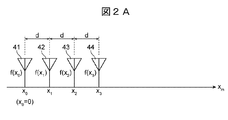
- the processing contents of the signal processing apparatus 10 will be described with reference to FIGS. 2A and 2B.
- the interval d of the receiving antennas is, for example, approximately 1 ⁇ 2 of the wavelength 33 of the received wave.
- the positions of the channels 41 to 44 of the receiving antenna are x 0 , x 1 , x 2 , and x 3 , and the first signal 31 from each channel 31. Let f (x 0 ), f (x 1 ), f (x 2 ), f (x 3 ).
- the first signal 31 from the receiving antenna is a signal of four receiving antennas arranged at intervals of substantially half a wavelength of the received wave.
- the first signal 31 from each channel is an IF (intermediate frequency) obtained by mixing, for example, a transmission wave modulated by an FCM (Fast Chirp Modulation) method and a reception wave received by each channel 41 to 44 by a mixer. It is a signal of each channel 41 to 44 at a predetermined frequency after further Fourier transforming the signal, and is a complex amplitude having phase information.
- IF intermediate frequency
- f (x 0 ) to f (x 3 ), which are the first signals 31 from each channel, are duplicated by the signal duplication unit 36, and the duplicated first signal 31 is input to the phase addition processing unit 38.
- the predetermined frequency corresponds to the distance information 32, for example, if the distance is R, this corresponds to the distance information 32.
- x 0 , x 1 , x 2 , and x 3 correspond to the installation position information 34 of each channel of the receiving antenna.
- the predetermined frequency may be, for example, a frequency at which the signal strength peaks.
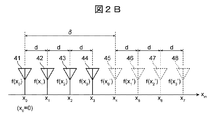
- the contents of generating the third signal of the extended receiving antenna array including the region outside the opening of the receiving antenna array will be described.
- the first signals f (x 0 ) to f (x 3 ) of each channel 41 to 44 of the receiving antenna are used, and the opening length ⁇ of the receiving antenna array is separated from the positions x 4 , x 5 , and so on.
- the second signal at x 6 and x 7 is calculated and generated.
- the aperture length ⁇ of the receiving antenna array corresponds to the extrapolation position information 35.
- Channels 45 to 48 in FIG. 2B are channels of the extended receiving antenna.
- the additional phase calculation unit 37 calculates the additional phase based on the distance information 32, the wavelength 33 of the received wave, the installation position information 34, and the extrapolation position information 35 (that is, ⁇ ). Then, assuming that the wavelength 33 of the received wave is ⁇ , the additional phase is calculated by the second term on the right side of the following equation (1).
- the phase addition processing unit 38 performs the addition processing of the equation (1) using the addition phase calculated by the addition phase calculation unit 37, and corresponds to the second signal of the positions x 4 , x 5 , x 6 , and x 7. Calculate f (x 0 '), f (x 1 '), f (x 2 '), f (x 3 ').
- the array signal expansion unit 39 extrapolates the calculated second signals f (x 0 '), f (x 1 '), f (x 2 '), and f (x 3 ') to the extrapolation position information 35 (. That is, by treating it as a signal at a position shifted by the amount of ⁇ ) and arranging it along with the original first signals f (x 0 ), f (x 1 ), f (x 2 ), and f (x 3). , Generates a third signal in the extended receive antenna array, including the area outside the aperture of the receive antenna array.
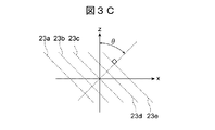
- FIGS. 3A to 3C are schematic views showing the position of the detected object and the wavefront shape of the received wave.
- FIG. 3A shows the positional relationship between the axis 22 in the direction in which the receiving antenna arrays are lined up and the reflection point 50 located at the coordinate A.
- the reflection point 50 indicates a reflection point when a radio wave radiated from a transmitting antenna is reflected from a detection object or a part of the detection object.
- the reflection point 50 exists at a position separated from the origin O of the axis 22 by a distance R, and is located in the direction of the direction ⁇ when viewed from the origin O.
- the reference numeral 21 is an arc having a radius R, and the reflection point 50 is located on the arc 21 having a radius R.
- Reference numeral 20 indicates an axis parallel to the axis 22 and separated by a distance R.
- the reflected wave propagates toward the receiving antenna array as a spherical wave centered on the reflection point 50.
- Reference numeral 23 indicates an equiphase plane of the reflected wave
- reference numeral 24 indicates a wave vector of the reflected wave.
- the phases 23a to 23e of the reflected wave can be regarded as a plane wave within the range of the opening of the receiving antenna array, and the discussion is advanced. The assumption that it is regarded as a plane wave is valid when the distance R is sufficiently longer than the aperture length.
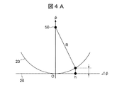
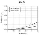
- FIG. 4A and 4B are diagrams showing the phase difference between a spherical wave and a plane wave.
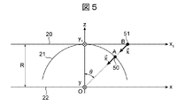
- FIG. 5 is a schematic diagram showing an object position having an orientation equivalent to the orientation of the detected object.
- the reflection point does not necessarily have to exist on the arc 21 in order to detect the direction ⁇ of the reflection point 50.
- the reflection point does not necessarily have to exist on the arc 21 in order to detect the direction ⁇ of the reflection point 50.
- the reflection point does not necessarily have to exist on the extension line of the origin O and the coordinate A and at the coordinate B (reference numeral 51) intersecting the axis 20, it is still the direction ⁇ . No.
- a phase difference corresponding to the distance between the coordinate A and the coordinate B occurs between the reflected wave when the coordinate A is used as the reflection point and the reflected wave when the coordinate B is used as the reflection point, but this phase is received. Since it is uniformly superimposed on the antenna array, there is no problem in calculating the phase gradient of the received signal in the receiving antenna array, which is required when estimating the orientation ⁇ . That is, when estimating the direction ⁇ , the processing is performed assuming that the reflection point exists on the axis 20. Therefore, in the following description, the discussion will proceed on the assumption that the reflection point is on the axis 20.
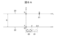
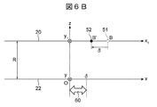
- FIG. 6A and 6B are schematic views showing a process of virtually shifting the position of the detected object in order to generate a second signal in the region outside the opening of the receiving antenna array.
- FIG. 6A is a schematic view showing the positional relationship between the reflection point 51 projected on the shaft 20 and the receiving antenna array opening.
- Reference numeral 60 indicates a range of the aperture of the receiving antenna array, and the aperture length is ⁇ . In such a positional relationship, for example, a method of estimating the received signal in the region 61 in which the receiving antenna is not actually arranged will be described below.
- the distance R is sufficiently far from the aperture length ⁇ . Under such conditions, it becomes the condition of Fraunhofer diffraction in wave optics, and the electric field distribution of the radio wave on the axis 20 and the electric field distribution of the radio wave on the axis 22 are as shown in the following equation (2), where k is the wave number. It can be related using the Fourier transform.
- the electric field distribution of the radio wave on the axis 20 is u (x 1 , y 1 , R)
- the electric field distribution of the radio wave on the axis 22 is u (x, y, 0).
- a (x 1 , y 1 , R) in the formula (2) is obtained by the following formula (3).
- the electric field distribution of the radio wave in the region 61 is the position B'(reference numeral) in which the position B of the reflection point 51 (that is, the above-mentioned coordinate B) is shifted by the opening length ⁇ . It can be considered to be equivalent to the electric field distribution of the radio wave in the region 60 when it exists in 52). It is impossible to physically shift the position of the physical space where the reflection points exist, but if the Fourier transform relationship as shown in Eq. (2) holds, the electric field distribution of the radio wave when the position is shifted is Fourier. From the transform formula, it can be expressed as a form obtained by multiplying the electric field distribution of the radio wave in the region 60 by the phase function as shown in the following equation (4).
- the wavelength ⁇ indicates the wavelength of the radio wave to be used, which is a self-explanatory value as a design value.
- the position shift ⁇ is also a trivial value as a design value.
- the distance R is not a design value because it changes according to the detected object, but as signal processing of the millimeter wave radar, there is generally a process of calculating the distance R of the detected object in the process before obtaining the arrival angle. Therefore, the calculation result may be used.
- variable x corresponds to the position of each antenna element constituting the receiving antenna array
- the specific value of the phase function of the second term on the right side of the equation (4) can be obtained by using the value of each variable described above. can. Further, by multiplying the received signal (that is, the first signal) from the reflection point at the position of the distance R by the phase function, the received signal (that is, the second signal) in the region outside the opening of the receiving antenna array is calculated. Can be generated.
- the received signal in the region outside the opening of the receiving antenna array is calculated, and the orientation is estimated in a form with enhanced resolution in the angular direction by using the extended receiving antenna array signal (that is, the third signal). It becomes possible.
- the reflection point does not actually exist on the axis 20, and this way of thinking is temporarily taken when estimating the direction. Therefore, for example, when the relative coordinates of the reflection points seen from a radar device equipped with a signal processing device are finally obtained, it is assumed that the reflection points exist on the arc 21, and the reflection points are combined with the azimuth ⁇ estimated by the above-mentioned grasping method. demand.
- the received signal that is, the second signal
- the signal processing device 10 of the present embodiment is also applied when two reflection points are present on the arc 21 having a radius R.
- the IF (intermediate frequency) signal obtained by mixing the transmitted wave and the received wave received by each channel by a mixer is Fourier transformed, it has a large value at a predetermined frequency corresponding to the distance R, which is the coordinate.
- the cause is the reflection point 53 located at the A 1 and the reflection point 54 located at the coordinate A 2.
- the reflection point 53 and the reflection point 54 are on the extension line of the origin O and the coordinate A 1 or the coordinate A 2 , and the coordinates B 1 (reference numeral 53 b) and the coordinate B 2 (reference numeral B 2) intersect with the axis 20. It is considered to exist in 54b).
- FIG. 8A and 8B are schematic views showing a process of virtually shifting the position of the detected object in order to generate a second signal in the region outside the opening of the receiving antenna array.
- FIG. 8A is a schematic view showing the positional relationship between the reflection points 53b and 54b projected on the shaft 20 and the receiving antenna array opening.
- Reference numeral 60 indicates a range of the aperture of the receiving antenna array, and the aperture length is ⁇ .
- the electric field distribution of the radio wave in the region 61 where the receiving antenna is not arranged shifts the position by the opening length ⁇ of the coordinate B 1 of the reflection point 53b as shown in FIG. 8B.
- coordinate B 1 and ', and the coordinates B 2 of the reflection point 54b is coordinate B 2 shifted by an amount position of the aperture length [delta]' can be considered wave electric field distribution and the equivalent in the region 60 when present in.
- the received signal (that is, the second signal) in the region 61 in which the receiving antenna is not actually arranged can be calculated.
- the received signal in the region outside the opening of the receiving antenna array is calculated, and the orientation is estimated in a form with enhanced resolution in the angular direction by using the extended receiving antenna array signal (that is, the third signal). It becomes possible.
- the signal duplication unit 36 duplicates the first signal 31, and the additional phase calculation unit 37 has the distance information 32, the received wave wavelength 33, the installation position information 34, and the outside.
- the additional phase is calculated based on the Fourier transform using the insertion position information 35, and the phase addition processing unit 38 adds the first signal 31 duplicated by the signal duplication unit 36 to the addition phase calculation unit 37.
- the phase addition processing the second signal in the region outside the opening of the receiving antenna array is generated, and the array signal expansion unit 39 with the first signal 31 and the second signal generated by the phase addition processing unit 38.
- the external position information 35 are arranged according to the external position information 35 to generate a third signal of the extended receiving antenna array including the region outside the opening of the receiving antenna array.
- the receiving antenna of the signal processing device 10 is composed of a receiving antenna actually arranged (hereinafter referred to as “existing receiving antenna”) and the above-mentioned expanded receiving antenna. Become. As a result, it becomes possible to realize high resolution in the angular direction not only for a single target but also for a multi-target.
- the signal processing apparatus includes the signal duplication unit 36, the additional phase calculation unit 37, the phase addition processing unit 38, and the array signal expansion unit 39.
- a distance detection unit, an orientation estimation unit, and the like may be further provided.
- the receiving antennas have been described with reference to an example in which they are arranged at equal intervals, but they may be arranged at irregular intervals. Further, the number of receiving antennas is not limited to the above, as long as the first signal 31 from the receiving antenna includes signals of at least one set of receiving antennas arranged at intervals of approximately half a wavelength of the received wave. It may be increased or decreased.
- a virtual antenna by MIMO Multi Input Multi Output
- the signal of the virtual antenna may be generated in advance by MIMO based on the signal from the existing receiving antenna, and the range including the virtual antenna may be regarded as the range of the opening of the receiving antenna array.
- the first signal 31 in FIG. 1 may include the signal of the virtual antenna by MIMO.
- the receiving antenna is composed of a real receiving antenna, a virtual antenna generated by MIMO, and an extended receiving antenna.
- the number of effective receiving antennas can be further increased, and it becomes easier to realize high resolution in the angular direction.
- FIG. 9 is a schematic view showing an embodiment of the radar device according to the present invention.
- the radar device 1 of the present embodiment includes an oscillator 11, a transmission unit 12, a plurality of (here, three) transmitting antennas 13, a plurality of (here, four) receiving antennas 14, and receiving.
- a unit 15, an A / D converter 16, a signal processing device 17, and a communication interface unit (communication I / F unit) 18 are provided.
- the four receiving antennas 14 form a receiving antenna array.
- the radar device 1 is mounted on a vehicle, for example, and is connected to a vehicle control device 2 separately provided on the vehicle.
- the oscillator 11 generates a frequency-modulated modulated signal and supplies the modulated signal to the transmitting unit 12 and the receiving unit 15.
- a PLL Phase Locked Loop
- VCO Voltage Controlled Oscillator
- the transmission unit 12 power-amplifies the modulation signal from the oscillator 11 to output the frequency-modulated transmission signal to the transmission antenna 13.
- This transmission signal is radiated as a radio wave directed around the vehicle, for example, in front of the vehicle, via the transmission antenna 13.
- the receiving unit 15 is obtained by reflecting a transmission signal radiated from the transmitting unit 12 via the transmitting antenna 13 by an object around the vehicle and inputting it to the receiving antenna 14. Receive a signal. Then, by mixing the received signal with the modulated signal from the oscillator 11, a beat signal corresponding to the frequency difference between these signals is generated, and frequency down-conversion is performed. The generated beat signal becomes digital data that has been A / D converted by the A / D converter 16 after the unnecessary frequencies have been cut through the band limiting filter, and the distance and speed to the objects around the vehicle by the signal processing device 17 are obtained. , And signal processing to calculate the arrival angle and the like.
- the signal processing device 17 includes a distance detection unit 17a, a speed detection unit 17b, a signal processing unit 17c, a direction estimation unit 17d, and a tracking unit 17e.
- the difference between the signal processing device 17 and the above-mentioned signal processing device 10 is that the distance detection unit 17a, the speed detection unit 17b, the direction estimation unit 17d, and the follow-up unit 17e are further provided. That is, the signal processing unit 17c of the signal processing device 17 is composed of the signal duplication unit 36, the additional phase calculation unit 37, the phase addition processing unit 38, and the array signal expansion unit 39, similarly to the signal processing device 10 described above. Is.
- the distance detection unit 17a performs distance detection and the speed detection unit 17b performs speed detection using A / D converted digital data. Further, the signal processing unit 17c calculates the received signal (that is, the second signal) in the region outside the opening of the receiving antenna array, and the direction estimation unit 17d performs the direction estimation. Further, the detected object is tracked by the tracking unit 17e. Then, these object information is transmitted to the vehicle control device 2 through the communication I / F unit 18.
- the radar device 1 configured as described above includes the signal processing device 17, the number of effective receiving antennas can be increased by signal processing as in the above-mentioned signal processing device 10, and the radar device 1 is not limited to a single target.
- the effect of achieving high resolution in the angular direction can be obtained even for multiple targets. As a result, the detection accuracy of the radar device 1 can be improved.
- the signal processing device 17 is the region outside the opening of the receiving antenna array as in the above-mentioned signal processing device 10. It is preferable to generate the second signal in. That is, as described above, assuming that the reflected wave from a single reflection point can be regarded as a plane wave in the receiving antenna array, a second signal is generated in the region outside the opening of the receiving antenna array, so that an error occurs when the wave deviates from the plane wave. growing. Further, as shown in FIG. 4B, the shorter the distance to the reflection point, the larger the amount of deviation. Therefore, in order to suppress the error, the second signal is generated in the region outside the opening of the receiving antenna array only when the distance is a predetermined distance (that is, the threshold value) or more.
- control process shown in FIG. 11 is repeatedly executed at a predetermined cycle.
- step S101 the distance detection unit 17a detects the distance from the receiving antenna array to the detected object based on the digital data A / D converted by the A / D converter 16.
- step S102 the speed detection unit 17b detects the speed of the detected object based on the A / D converted digital data.
- the speed detection is performed after the distance detection, but the distance detection may be performed after the speed detection, or the distance detection and the speed detection may be performed at the same time.
- step S104 following step S103 the signal processing unit 17c acquires the detection distance that is the result of step S101, and determines whether or not the acquired detection distance is equal to or greater than the threshold value.
- the threshold value is set in advance based on, for example, an empirical value, and is stored in the signal processing unit 17c.
- step S105 If it is determined that the detection distance is smaller than the threshold value, the control process proceeds to step S105 described later. On the other hand, if it is determined that the detection distance is equal to or greater than the threshold value, the control process proceeds to step S104, and the second signal is generated in the region outside the opening of the receiving antenna array.
- the signal duplication unit 36, the additional phase calculation unit 37, and the phase addition processing unit 38 perform each processing as described above to generate a second signal in the region outside the opening of the receiving antenna array.
- the array signal expansion unit 39 is based on the generated second signal, first signal 31, and extrapolation position information 35, and is an expanded receiving antenna array including a region outside the opening of the receiving antenna array.
- a third signal may be generated.
- step S105 the direction estimation unit 17d estimates the direction of the detected object based on the second signal or the like in the region outside the opening of the receiving antenna array generated in step S104.
- step S106 the tracking unit 17e follows the detected object by performing tracking processing. Then, when step S106 is completed, a series of control processes is completed.
- the signal processing device 17 only when the detection distance is equal to or greater than the threshold value, the signal processing device 17 generates the second signal in the region outside the opening of the receiving antenna array, thereby suppressing the error that occurs when the distance to the detection object is short. can do.
- the configuration of the radar device 1 described here is merely an example, and for example, the number of antenna elements of the transmitting antenna 13 and the receiving antenna 14 is not limited to the configuration shown in FIG.
Landscapes
- Engineering & Computer Science (AREA)
- Radar, Positioning & Navigation (AREA)
- Remote Sensing (AREA)
- Computer Networks & Wireless Communication (AREA)
- Physics & Mathematics (AREA)
- General Physics & Mathematics (AREA)
- Radar Systems Or Details Thereof (AREA)
Abstract
信号処理装置10は。受信アンテナからの第1信号31を複製する信号複製部36と、距離情報32、受信波の波長33、設置位置情報34及び設置位置情報34に基づいて付加位相を算出する付加位相算出部37と、信号複製部36で複製した第1信号31に対し、付加位相算出部37で算出した付加位相を付加処理することで、受信アンテナアレーの開口外の領域の第2信号を生成する位相付加処理部38と、受信アンテナアレーの開口外の領域の第2信号と第1信号31とを外挿位置情報35に応じて並べることにより、受信アンテナアレーの開口外の領域を含む拡張した受信アンテナアレーの第3信号を生成するアレー信号拡張部39とを備える。
Description
本発明は、信号処理装置及びそれを備えたレーダ装置に関する。
本願は、2020年7月3日に出願された日本国特願2020-115591号に基づき優先権を主張し、その内容をここに援用する。
本願は、2020年7月3日に出願された日本国特願2020-115591号に基づき優先権を主張し、その内容をここに援用する。
周波数30GHz~300GHzの電波であるミリ波は、電波の中でも光に近い周波数帯であり、直進性が強く、耐環境性(雨、霧、雪、汚れ等)に優れる性質を有する。この性質をセンサとして応用したミリ波レーダは、離れた検知物体との距離や速度、及び検知物体の方位を計測することができ、自動運転(Autonomous Driving:AD)及び先端運転支援システム(Advanced Driver Assistance Systems:ADAS)の主要センサとして採用されている。今後はADやADASの高度化に伴い、ミリ波レーダによるセンシングが必要になるシーンは拡大し、特に検知物体が密集して配置された中でも検知対象を的確に検知できるよう、高分解能化が必要になる。
ミリ波レーダの高分解能化は主に2つの観点がある。1つ目の観点は距離方向の高分解能化であり、これは電波の周波数帯域を広くすることで実現可能である。例えば4GHzの帯域幅を有する79GHz帯のミリ波を用いることで、距離方向において20cm程度の高分解能化を実現できている(非特許文献1)。2つ目の観点は角度方向の高分解能化である。角度方向の高分解能化を実現するためには、基本的に受信アンテナアレーの開口長を長くすることが必要である。従って、受信アンテナアレーを構成する受信アンテナ数を増やすことが必要となる。しかしながら、受信アンテナ数を増やすと、多くのアンテナを扱うために駆動用の回路も増やす必要がある。また、多くの受信信号を基板上で伝送するため、配線パターンの規模が大きくなり、更には多くの受信信号を扱うために回路の規模も大きくなる。その結果、コストが高くなる問題が生じる。
そこで、仮想的に受信アンテナ数を信号処理によって増やす方法が提案されている。例えば特許文献1では、アンテナ拡張部が以下の各処理を行うことを特徴とする信号処理方法が開示されている。すなわち、アンテナ拡張部は、連続する2以上の受信アンテナに関するデータを当該2以上の受信アンテナのうちの一方の端の受信アンテナの位置を他方の端の受信アンテナの位置に合わせるように、複数の受信アンテナに関するデータに追加的に配置する処理と、追加的に配置した2以上の受信アンテナに関するデータについて、複数の受信アンテナのうちの他方の端の受信アンテナの位置における2つのデータの位相が一致するように位相を回転させる処理と、位相を回転させた2以上の受信アンテナに関するデータを、複数の受信アンテナのうちの他方の端の受信アンテナの位置においては当該受信アンテナに関するデータを採用して複数の受信アンテナに関するデータと連結させる処理と、を行う。このようにすることで、上記複数の受信アンテナが等間隔で並べられてなる受信アンテナアレーの信号分解能を効果的に向上することができる。
K. Ohguchi, M. Shono, M. Kishida, "79GHz band ultra-wideband automotive radar", Fujitsu Ten Tech. J., vol. 39, pp. 9-14, 2013
ところで、特許文献1に記載の信号処理方法では、受信アンテナアレーで受信する信号の位相変化は線形であることを条件としている。検知物体が1つしか存在しないシングルターゲットの場合、本条件は妥当であると考えられるが、検知物体が複数存在するマルチターゲットの場合、受信信号の位相変化は必ずしも線形とは限らず、非線形な状態が発生する。このため、マルチターゲットに対しては、特許文献1の方法を用いた場合、実際の受信アンテナの外側の領域に配置された仮想アンテナの受信信号を精度良く求めることができず、角度方向の高分解能化を実現することができない問題が生じる。
本発明は、このような技術課題を解決するためになされたものであって、シングルターゲットに限らずマルチターゲットに対しても角度方向の高分解能化を実現できる信号処理装置及びそれを備えたレーダ装置を提供することを目的とする。
本発明に係る信号処理装置は、受信アンテナアレーを構成する受信アンテナからの第1信号に対し、前記受信アンテナアレーから検知物体までの距離に応じた位相情報を付加することにより、前記受信アンテナアレーの開口外の領域の第2信号を生成することを特徴としている。
本発明に係る信号処理装置では、受信アンテナからの第1信号に対し受信アンテナアレーから検知物体までの距離に応じた位相情報を付加することにより受信アンテナアレーの開口外の領域の第2信号を生成するので、実効的な受信アンテナ数を信号処理で増やすことができる。このため、シングルターゲットに限らずマルチターゲットに対しても角度方向の高分解能化を実現することができる。
本発明によれば、シングルターゲットに限らずマルチターゲットに対しても角度方向の高分解能化を実現することができる。
以下、図面を参照して、本発明に係る信号処理装置の実施形態とレーダ装置の実施形態とを順に説明する。
[信号処理装置について]
図1は本発明に係る信号処理装置の実施形態を示すブロック図である。本実施形態の信号処理装置10は、物体を検知するレーダ装置(後述する)1に設けられており、受信アンテナアレーの開口外の領域における信号の算出を始め、レーダ装置1に関する各信号処理を行う装置である。図1に示すように、この信号処理装置10は主に、信号複製部36、付加位相算出部37、位相付加処理部38、及びアレー信号拡張部39を備えている。
図1は本発明に係る信号処理装置の実施形態を示すブロック図である。本実施形態の信号処理装置10は、物体を検知するレーダ装置(後述する)1に設けられており、受信アンテナアレーの開口外の領域における信号の算出を始め、レーダ装置1に関する各信号処理を行う装置である。図1に示すように、この信号処理装置10は主に、信号複製部36、付加位相算出部37、位相付加処理部38、及びアレー信号拡張部39を備えている。
信号複製部36には、受信アンテナアレーを構成する受信アンテナの各チャンネルからの第1信号31(以下、単に「第1信号31」という)が入力される。信号複製部36は、第1信号31を複製し、複製した第1信号31を位相付加処理部38に出力する。
付加位相算出部37には、受信アンテナアレーから検知物体までの距離情報32(以下、単に「距離情報32」という)、受信波の波長33、受信アンテナの設置位置情報34(以下、単に「設置位置情報34」という)、及び受信アンテナアレーの開口長である外挿位置情報35がそれぞれ入力される。付加位相算出部37は、入力されたこれらの情報に基づき、後述する算出方法を用いて付加位相を算出し、算出した付加位相を位相付加処理部38に出力する。
位相付加処理部38は、信号複製部36によって複製された第1信号31に対し、付加位相算出部37によって算出された付加位相を付加処理することで、受信アンテナアレーの開口外の領域の第2信号を生成する。そして、位相付加処理部38は、生成した第2信号にアレー信号拡張部39に出力する。
アレー信号拡張部39には、位相付加処理部38から入力された第2信号のほか、更に第1信号31及び外挿位置情報35も入力される。アレー信号拡張部39は、第2信号と第1信号31とを外挿位置情報35に応じて並べることにより、受信アンテナアレーの開口外の領域を含む拡張した受信アンテナアレーの第3信号を生成する。
以下、図2A及び図2Bを参照して信号処理装置10の処理内容について説明する。ここでは、4つの受信アンテナが等間隔dで配置されてなる受信アンテナアレーを備えた例を挙げて説明する。受信アンテナの間隔dは、例えば受信波の波長33の略1/2である。図2Aに示すように、受信アンテナの各チャンネル41~44の位置(言い換えれば、受信アンテナの設置位置)はx0、x1、x2、x3であり、各チャンネルからの第1信号31をf(x0)、f(x1)、f(x2)、f(x3)とする。すなわち、受信アンテナからの第1信号31は、受信波の略半波長の間隔で並ぶ4つの受信アンテナの信号である。このように受信波の略半波長の間隔で受信アンテナを配置することで、誤差を少なくすることができるので、検知精度を高める効果を期待できる。
各チャンネルからの第1信号31とは、例えばFCM(Fast Chirp Modulation)方式で変調された送信波と各チャンネル41~44が受信する受信波とをミキサによって混合して得られるIF(中間周波数)信号を更にフーリエ変換した後の所定の周波数における各チャンネル41~44の信号であり、位相情報を有する複素振幅である。
そして、各チャンネルからの第1信号31であるf(x0)~f(x3)が信号複製部36で複製され、複製された第1信号31は位相付加処理部38に入力される。上記所定の周波数は距離情報32に対応するため、例えば距離をRとすると、これが上述の距離情報32に対応する。x0、x1、x2、x3が受信アンテナの各チャンネルの設置位置情報34に対応する。なお、所定の周波数は、例えば信号強度がピークになる周波数としても良い。
次に、図2Bを用いて、受信アンテナアレーの開口外の領域を含む拡張した受信アンテナアレーの第3信号を生成する内容について説明する。本実施形態では、まず、受信アンテナの各チャンネル41~44の第1信号f(x0)~f(x3)を用いて、受信アンテナアレーの開口長δ離れた位置x4、x5、x6、x7における第2信号を算出し生成する。受信アンテナアレーの開口長δは、外挿位置情報35に対応する。図2B中のチャンネル45~48は、拡張した受信アンテナのチャンネルである。
上述したように、付加位相算出部37は、距離情報32、受信波の波長33、設置位置情報34、及び外挿位置情報35(すなわち、δ)に基づいて、付加位相を算出する。そして、受信波の波長33をλとすると、下記式(1)の右辺第2項が算出される付加位相となる。

位相付加処理部38は、付加位相算出部37で算出した付加位相を用いて、式(1)の付加処理を行い、位置x4、x5、x6、x7の第2信号に相当するf(x0’)、f(x1’)、f(x2’)、f(x3’)を算出する。
次に、アレー信号拡張部39は、算出された第2信号f(x0’)、f(x1’)、f(x2’)、f(x3’)を外挿位置情報35(すなわち、δ)の分だけシフトした位置の信号と捉えて、元の第1信号であるf(x0)、f(x1)、f(x2)、f(x3)と並べることで、受信アンテナアレーの開口外の領域を含む拡張した受信アンテナアレーの第3信号を生成する。
続いて、図3A~8Bを参照し、本発明者らが受信アンテナアレーの開口外の領域の第2信号を算出するために式(1)を用いる妥当性を説明する。
図3A~図3Cは検知物体の位置と受信波の波面形状を示す概略図である。図3Aは受信アンテナアレーが並ぶ方向の軸22と、座標Aに位置する反射点50との位置関係を示したものである。反射点50は、送信アンテナから放射された電波が検知物体又は検知物体の一部分から反射した際の反射点を示したものである。この反射点50は、軸22の原点Oから距離R離れた位置に存在し、且つ原点Oから見て方位θの方向に位置している。そして、符号21は半径Rの円弧であり、反射点50は半径Rの円弧21上に位置する。符号20は、軸22と平行で距離R離れた軸を示している。
図3Bに示すように、送信アンテナから発した電波が反射点50によって反射されると、その反射波は反射点50を中心とする球面波として受信アンテナアレーに向かって伝搬する。符号23は反射波の等位相面、符号24は反射波の波数ベクトルを示している。本実施形態では、受信アンテナアレーの開口の範囲内では、図3Cに示すように、反射波の位相23a~23eは平面波とみなせるとして議論を進める。平面波とみなす仮定は、開口長に比べて距離Rが十分に長い場合は妥当である。
図4A及び図4Bは球面波と平面波の位相差を示す図である。まず、図4Aに示すように、球面波23と平面波25との位相差Δφは、位相差Δφ=0となる中心からの位置hに応じて大きくなるが、距離Rが長くなるほど位相差Δφは小さくなる。図4Bは横軸を位置h、縦軸をΔφとして、距離R=10m及びR=20mの場合の両者の関係を示すグラフである。図4Bから、距離Rが長くなるほど位相差Δφは小さくなるのが分かる。ここで、位相差Δφは電波の波長で正規化した値であり、電波の周波数は77GHzとして計算している。そして、例えばR=10mにおいて位置hが50mm程度の場合、位相差Δφは0.03λ程度と小さく、平面波としてみなしても問題無いと考えられる。
図5は検知物体の方位と等価な方位となる物体位置を示す概略図である。受信アンテナアレーにおいて反射点50からの反射波が平面波とみなせる場合、反射点50の方位θを検知する上では、反射点は必ずしも円弧21上に存在している必要はない。例えば図5に示すように、反射点は原点Oと座標Aの延長線上で、且つ軸20と交わる座標B(符号51)に存在していると捉えても、方位θであることには変わらない。
この場合、座標Aを反射点とした場合の反射波と座標Bを反射点とした場合の反射波とでは、座標Aと座標B間の距離に相当する位相差が生じるが、この位相は受信アンテナアレーに一律に重畳されるため、方位θを見積もる際に必要となる受信アンテナアレーにおける受信信号の位相傾きを計算する上では支障がない。すなわち、方位θを推定する際に、反射点は軸20上に存在するとして処理を行う。このため、以降の説明では、反射点は軸20上にある前提で議論を進める。
図6A及び図6Bは受信アンテナアレーの開口外の領域の第2信号を生成するために、検知物体の位置を仮想的にずらす処理を示す概略図である。図6Aは軸20上に投影した反射点51と受信アンテナアレー開口との位置関係を示した概略図である。符号60は受信アンテナアレーの開口の範囲を示しており、開口長はδとしている。このような位置関係において、例えば実際に受信アンテナが配置されていない領域61の受信信号を見積もる方法を以下に述べる。
ここでは、反射点からの反射波は受信アンテナアレーにおいて平面波とみなせるとしているので、開口長δに比べて距離Rは十分に遠いことになる。このような条件では、波動光学で言うところのフラウンホーファ回折の条件となり、軸20における電波の電場分布と、軸22における電波の電場分布は波数をkとすると、下記式(2)に示すようなフーリエ変換を用いて関係付けることができる。ここで、軸20上における電波の電場分布をu(x1,y1,R)、軸22上における電波の電場分布をu(x,y,0)としている。

なお、式(2)中のA(x1,y1,R)は下記式(3)によって求められる。

領域61における電波の電場分布は、見方を変えると図6Bに示すように、反射点51の位置B(すなわち、上述の座標B)が開口長δの分だけ位置をシフトした位置B’(符号52)に存在する時の領域60における電波の電場分布と等価と考えることができる。反射点が存在する物理空間を物理的に位置シフトすることは不可能であるが、式(2)に示すようなフーリエ変換の関係が成り立つとすると、位置シフトした場合の電波の電場分布はフーリエ変換の公式から、下記式(4)に示すように領域60における電波の電場分布に位相関数を掛け合わせた形として表現することができる。
言い換えれば、位置Bに存在する反射点51に対して、領域60に存在する受信アンテナアレーの受信信号に対して、下記式(4)の右辺第2項の位相関数を掛け合わせることで、実際に受信アンテナが配置されていない領域61の受信信号を算出することができる。

式(4)の右辺第2項の位相関数における変数のうち、波長λは使用する電波の波長を示しており、設計値として自明な値である。位置シフトδも設計値として自明な値である。一方、距離Rは検知物体に応じて変化するため設計値ではないが、ミリ波レーダの信号処理として、一般的に到来角度を求める前の処理において検知物体の距離Rを算出する処理が存在するため、その算出結果を用いれば良い。変数xは受信アンテナアレーを構成する各アンテナ素子の位置に対応するので、上述した各変数の値を用いることで式(4)の右辺第2項の位相関数の具体的な値を求めることができる。更に、距離Rの位置にある反射点からの受信信号(すなわち、第1信号)に位相関数を掛け合わせることで、受信アンテナアレーの開口外の領域の受信信号(すなわち、第2信号)を算出して生成することができる。
そして、受信アンテナアレーの開口外の領域の受信信号を算出し、拡張した受信アンテナアレーの信号(すなわち、第3信号)を用いることにより、角度方向の分解能化を高めた形で方位を推定することが可能となる。ところで、反射点は実際に軸20上に存在するわけではなく、あくまでも方位を推定する際に、一時的にこのような捉え方をしている。従って、例えば信号処理装置を備えたレーダ装置から見た反射点の相対座標を最終的に求める場合は、反射点は円弧21上に存在するとし、上述の捉え方で推定した方位θと組み合わせて求める。
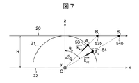
以上の説明では、内容がより理解しやすくするために、距離Rの位置に反射点が一つの場合について説明したが、本実施形態は反射点が2つ以上ある場合でも同様の処理を行うことで、受信アンテナアレーの開口外の領域の受信信号(すなわち、第2信号)を算出することができる。例えば図7に示すように、本実施形態の信号処理装置10は、反射点が半径Rの円弧21上に2つ存在している場合にも適用される。
すなわち、送信波と各チャンネルが受信する受信波をミキサによって混合して得られるIF(中間周波数)信号をフーリエ変換した際に、距離Rに相当する所定周波数において大きな値を有し、それが座標A1に位置する反射点53及び座標A2に位置する反射点54を起因としている場合を考える。この場合において、上述と同様に、反射点53及び反射点54は原点Oと座標A1または座標A2の延長線上で、且つ軸20と交わる座標B1(符号53b)及び座標B2(符号54b)に存在していると捉える。
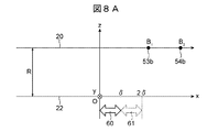
図8A及び図8Bは受信アンテナアレーの開口外の領域の第2信号を生成するために、検知物体の位置を仮想的にずらす処理を示す概略図である。図8Aは軸20上に投影した反射点53b及び54bと受信アンテナアレー開口との位置関係を示した概略図である。符号60は受信アンテナアレーの開口の範囲を示しており、開口長はδとしている。
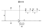
このような位置関係において、受信アンテナが配置されていない領域61における電波の電場分布は、見方を変えると図8Bに示す通り、反射点53bの座標B1が開口長δの分だけ位置をシフトした座標B1’、及び反射点54bの座標B2が開口長δの分だけ位置をシフトした座標B2’に存在する時の領域60における電波の電場分布と等価と考えることができる。
反射点が存在する物理空間を物理的に位置シフトすることは不可能であるが、式(2)に示すようなフーリエ変換の関係が成り立つとすると、位置シフトした場合の電波の電場分布はフーリエ変換の公式から、上記式(4)に示すように領域60における電波の電場分布に位相関数を掛け合わせた形として表現することができる。
言い換えれば、座標B1と座標B2に存在する反射点53bと54bに対して、領域60に存在する受信アンテナアレーの受信信号(すなわち、第1信号)に対して、式(4)の右辺第2項の位相関数を掛け合わせることで、実際に受信アンテナが配置されていない領域61の受信信号(すなわち、第2信号)を算出することができる。そして、受信アンテナアレーの開口外の領域の受信信号を算出し、拡張した受信アンテナアレーの信号(すなわち、第3信号)を用いることにより、角度方向の分解能化を高めた形で方位を推定することが可能となる。
以上のように構成された信号処理装置10では、信号複製部36が第1信号31を複製しており、付加位相算出部37が距離情報32、受信波の波長33、設置位置情報34及び外挿位置情報35を用いてフーリエ変換に基づいて付加位相を算出しており、位相付加処理部38が信号複製部36により複製された第1信号31に対し付加位相算出部37により算出された付加位相を付加処理することで、受信アンテナアレーの開口外の領域の第2信号を生成しており、アレー信号拡張部39が第1信号31と位相付加処理部38により生成された第2信号とを外挿位置情報35に応じて並べることにより、受信アンテナアレーの開口外の領域を含む拡張した受信アンテナアレーの第3信号を生成する。このようにすることで、実効的な受信アンテナ数を信号処理で増やすことができる。すなわち、本実施形態によれば、信号処理装置10の受信アンテナが、実際に配置されている受信アンテナ(以下「実在受信アンテナ」という)と、上述の拡張した受信アンテナとによって構成されることになる。その結果、シングルターゲットに限らずマルチターゲットに対しても角度方向の高分解能化を実現することが可能になる。
なお、本発明に係る信号処理装置は、本実施形態の内容を逸脱しない範囲で自由に設計して構わない。例えば、本実施形態において、信号処理装置が信号複製部36、付加位相算出部37、位相付加処理部38及びアレー信号拡張部39を備えた例を挙げて説明したが、信号処理装置は、例えば後述する図10に示すように、距離検知部や方位推定部等を更に備えても良い。また、本実施形態において、受信アンテナは等間隔に配置される例を挙げて説明したが、不等間隔で配置されても構わない。更に、受信アンテナの数は上述の内容に制限されず、受信アンテナからの第1信号31が受信波の略半波長の間隔で並ぶ少なくとも1組の受信アンテナの信号を含むものであれば、適宜増減されても良い。
また、図6A、図6B、図8A及び図8Bの符号60で示した受信アンテナアレーの開口の範囲内には、例えばMIMO(Multi Input Multi Output)による仮想アンテナを含んでも良い。すなわち、実在受信アンテナからの信号を基にMIMOによって仮想アンテナの信号を事前に生成し、該仮想アンテナを含む範囲を受信アンテナアレーの開口の範囲内と捉えても構わない。この場合、図1における第1信号31にMIMOによる仮想アンテナの信号を含んでも良い。
このようにすれば、受信アンテナは、実在受信アンテナと、MIMOによって生成される仮想アンテナと、拡張した受信アンテナとによって構成されることになる。その結果、実効的な受信アンテナ数を更に増やすことができるので、角度方向の高分解能化が更に実現し易くなる。
[信号処理装置を備えたレーダ装置について]
図9は本発明に係るレーダ装置の実施形態を示す概略図である。図9に示すように、本実施形態のレーダ装置1は、発振器11、送信部12、複数(ここでは、3つ)の送信アンテナ13、複数(ここでは、4つ)の受信アンテナ14、受信部15、A/D変換器16、信号処理装置17、及び通信インターフェース部(通信I/F部)18を備えている。4つの受信アンテナ14は、受信アンテナアレーを構成する。このレーダ装置1は、例えば車両に搭載され、車両に別途設けられた車両制御装置2に接続されている。
図9は本発明に係るレーダ装置の実施形態を示す概略図である。図9に示すように、本実施形態のレーダ装置1は、発振器11、送信部12、複数(ここでは、3つ)の送信アンテナ13、複数(ここでは、4つ)の受信アンテナ14、受信部15、A/D変換器16、信号処理装置17、及び通信インターフェース部(通信I/F部)18を備えている。4つの受信アンテナ14は、受信アンテナアレーを構成する。このレーダ装置1は、例えば車両に搭載され、車両に別途設けられた車両制御装置2に接続されている。
発振器11は、周波数変調された変調信号を発生し、送信部12及び受信部15に変調信号を供給する。発振器11には、例えばVCO(Voltage Controlled Oscillator)と逓倍器等を含んで構成されたPLL(Phase Locked Loop)が用いられる。送信部12は、車両周囲の物体を検知する際に、発振器11からの変調信号を電力増幅することで、周波数変調された送信信号を送信アンテナ13へ出力する。この送信信号は、送信アンテナ13を介して車両の周囲、例えば車両前方に向けた電波として放射される。
受信部15は、車両周囲の物体を検知するため、送信部12から送信アンテナ13を介して放射された送信信号が車両周囲の物体で反射されて受信アンテナ14に入力されることで得られた信号を受信する。そして、受信信号を発振器11からの変調信号とミキシングすることで、これらの信号の周波数差に応じたビート信号を生成し、周波数ダウンコンバートを行う。生成されたビート信号は、帯域制限フィルタを通して不要周波数がカットされた後、A/D変換器16でA/D変換されたデジタルデータとなり、信号処理装置17で車両周囲の物体との距離、速度、及び到来角度等を算出するための信号処理を行う。
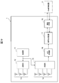
信号処理装置17は、図10に示すように、距離検知部17a、速度検知部17b、信号処理部17c、方位推定部17d及び追従部17eを備えている。この信号処理装置17と上述の信号処理装置10との相違点は、距離検知部17a、速度検知部17b、方位推定部17d及び追従部17eを更に備えることである。すなわち、信号処理装置17の信号処理部17cは、上述の信号処理装置10と同様に、信号複製部36、付加位相算出部37、位相付加処理部38及びアレー信号拡張部39により構成されたものである。
このような構造を有する信号処理装置17では、A/D変換されたデジタルデータを用いて距離検知部17aによって距離検知、速度検知部17bによって速度検知がそれぞれ行われる。更に、信号処理部17cによって受信アンテナアレーの開口外の領域の受信信号(すなわち、第2信号)が算出され、方位推定部17dによって方位推定が行われる。また、検知物体は追従部17eでトラッキング処理が行われる。そして、これらの物体情報は、通信I/F部18を通じて車両制御装置2へと送信される。
以上のように構成されたレーダ装置1では、信号処理装置17を備えるので、上述の信号処理装置10と同様に、実効的な受信アンテナ数を信号処理で増やすことができ、シングルターゲットに限らずマルチターゲットに対しても角度方向の高分解能化を実現できる効果を得られる。その結果、レーダ装置1の検知精度を向上することができる。
また、本実施形態において、受信アンテナアレーから検知物体までの距離が予め設定された閾値以上の場合にのみ、信号処理装置17が上述の信号処理装置10と同様に受信アンテナアレーの開口外の領域における第2信号を生成することが好ましい。すなわち、上述した通り、単一の反射点からの反射波が受信アンテナアレーにおいて平面波とみなせるとして、受信アンテナアレーの開口外の領域における第2信号を生成するため、平面波から乖離する場合は誤差が大きくなる。また、図4Bに示す通り、反射点までの距離が短いほど乖離量は大きい。そこで、誤差を抑制するために、所定の距離(すなわち、閾値)以上の場合に限り、受信アンテナアレーの開口外の領域における第2信号の生成が行われる。
以下、図11を参照してそれを詳細に説明する。なお、図11に示す制御処理は、所定の周期で繰り返し実行される。
まず、ステップS101では、距離検知部17aは、A/D変換器16によってA/D変換されたデジタルデータに基づき、受信アンテナアレーから検知物体までの距離検知を行う。ステップS101に続くステップS102では、速度検知部17bは、A/D変換されたデジタルデータに基づいて検知物体の速度検知を行う。本実施形態では、距離検知の後に速度検知が行われるが、速度検知の後に距離検知が行われても良く、或いは距離検知及び速度検知が同時に行われても良い。
ステップS103に続くステップS104では、信号処理部17cは、ステップS101の結果である検知距離を取得し、取得した検知距離が閾値以上であるか否かを判断する。閾値は、例えば経験値に基づいて予め設定され、信号処理部17cに記憶されている。
検知距離が閾値よりも小さいと判断された場合、制御処理は後述するステップS105に進む。一方、検知距離が閾値以上であると判断された場合、制御処理はステップS104に進み、受信アンテナアレーの開口外の領域における第2信号の生成が行われる。このとき、信号複製部36、付加位相算出部37及び位相付加処理部38は、上述したように各処理を行うことで、受信アンテナアレーの開口外の領域における第2信号を生成する。また、このとき、アレー信号拡張部39は、生成された第2信号、第1信号31、及び外挿位置情報35に基づいて、受信アンテナアレーの開口外の領域を含む拡張した受信アンテナアレーの第3信号を生成しても良い。
ステップS104に続くステップS105では、方位推定部17dは、ステップS104で生成された受信アンテナアレーの開口外の領域の第2信号等に基づいて、検知物体の方位推定を行う。ステップS105に続くステップS106では、追従部17eは、トラッキング処理を行うことにより検知物体への追従を行う。そして、ステップS106が終わると、一連の制御処理は終了する。
このように検知距離が閾値以上の場合に限り、信号処理装置17が受信アンテナアレーの開口外の領域における第2信号の生成を行うことで、検知物体までの距離が短い場合に生じる誤差を抑制することができる。
なお、ここで説明したレーダ装置1の構成は、あくまで一例であり、例えば、送信アンテナ13及び受信アンテナ14のアンテナ素子数は、図9に示す構成に限定されるものではない。
以上、本発明の実施形態について詳述したが、本発明は、上述の実施形態に限定されるものではなく、特許請求の範囲に記載された本発明の精神を逸脱しない範囲で、種々の設計変更を行うことができるものである。
1 レーダ装置
2 車両制御装置
10,17 信号処理装置
11 発振器
12 送信部
13 送信アンテナ
14 受信アンテナ
15 受信部
16 A/D変換器
17a 距離検知部
17b 速度検知部
17c 信号処理部
17d 方位推定部
17e 追従部
18 通信I/F部
36 信号複製部
37 付加位相算出部
38 位相付加処理部
39 アレー信号拡張部
2 車両制御装置
10,17 信号処理装置
11 発振器
12 送信部
13 送信アンテナ
14 受信アンテナ
15 受信部
16 A/D変換器
17a 距離検知部
17b 速度検知部
17c 信号処理部
17d 方位推定部
17e 追従部
18 通信I/F部
36 信号複製部
37 付加位相算出部
38 位相付加処理部
39 アレー信号拡張部
Claims (10)
- 受信アンテナアレーを構成する受信アンテナからの第1信号に対し、前記受信アンテナアレーから検知物体までの距離に応じた位相情報を付加することにより、前記受信アンテナアレーの開口外の領域の第2信号を生成することを特徴とする信号処理装置。
- 前記受信アンテナからの第1信号を複製する信号複製部と、
前記受信アンテナアレーから前記検知物体までの距離情報、受信波の波長、前記受信アンテナの設置位置情報、及び前記受信アンテナアレーの開口長である外挿位置情報に基づいて付加位相を算出する付加位相算出部と、
前記信号複製部により複製された第1信号に対し、前記付加位相算出部により算出された付加位相を付加処理することで、前記受信アンテナアレーの開口外の領域の第2信号を生成する位相付加処理部と、
を備える請求項1に記載の信号処理装置。 - 前記位相付加処理部により生成された前記受信アンテナアレーの開口外の領域の第2信号と前記受信アンテナからの第1信号とを前記外挿位置情報に応じて並べることにより、前記受信アンテナアレーの開口外の領域を含む拡張した受信アンテナアレーの第3信号を生成するアレー信号拡張部を更に備える請求項2に記載の信号処理装置。
- 前記付加位相算出部は、前記受信アンテナアレーから前記検知物体までの距離情報、前記受信波の波長、前記受信アンテナの設置位置情報、及び前記外挿位置情報を用いて、フーリエ変換に基づいて付加位相を算出する請求項2又は3に記載の信号処理装置。
- 前記位相付加処理部は、前記信号複製部により複製された第1信号に対し、前記付加位相算出部により算出された付加位相を掛け合わせることにより、前記受信アンテナアレーの開口外の領域の第2信号を生成する請求項2~4のいずれか一項に記載の信号処理装置。
- 前記受信アンテナからの第1信号は、前記受信波の略半波長の間隔で並ぶ少なくとも1組の受信アンテナの信号を含む請求項2~5のいずれか一項に記載の信号処理装置。
- 前記受信アンテナは、仮想アンテナを含む請求項1~6のいずれか一項に記載の信号処理装置。
- 前記仮想アンテナは、MIMO(Multi Input Multi Output)によって生成される請求項7に記載の信号処理装置。
- 前記信号処理装置は、前記受信アンテナアレーから前記検知物体までの距離が閾値以上の場合に、前記受信アンテナアレーの開口外の領域の第2信号を生成する請求項1~8のいずれか一項に記載の信号処理装置。
- 請求項1~9のいずれか一項に記載の信号処理装置を備えることを特徴とするレーダ装置。
Priority Applications (2)
| Application Number | Priority Date | Filing Date | Title |
|---|---|---|---|
| DE112021002497.3T DE112021002497T5 (de) | 2020-07-03 | 2021-05-12 | Signalverarbeitungsvorrichtung und damit versehene radarvorrichtung |
| JP2022533710A JP7474850B2 (ja) | 2020-07-03 | 2021-05-12 | 信号処理装置及びそれを備えたレーダ装置 |
Applications Claiming Priority (2)
| Application Number | Priority Date | Filing Date | Title |
|---|---|---|---|
| JP2020-115591 | 2020-07-03 | ||
| JP2020115591 | 2020-07-03 |
Publications (1)
| Publication Number | Publication Date |
|---|---|
| WO2022004140A1 true WO2022004140A1 (ja) | 2022-01-06 |
Family
ID=79315218
Family Applications (1)
| Application Number | Title | Priority Date | Filing Date |
|---|---|---|---|
| PCT/JP2021/018030 Ceased WO2022004140A1 (ja) | 2020-07-03 | 2021-05-12 | 信号処理装置及びそれを備えたレーダ装置 |
Country Status (3)
| Country | Link |
|---|---|
| JP (1) | JP7474850B2 (ja) |
| DE (1) | DE112021002497T5 (ja) |
| WO (1) | WO2022004140A1 (ja) |
Citations (4)
| Publication number | Priority date | Publication date | Assignee | Title |
|---|---|---|---|---|
| JP2009188999A (ja) * | 2008-02-07 | 2009-08-20 | Saab Ab | 広帯域アンテナパターン |
| JP2011128088A (ja) * | 2009-12-18 | 2011-06-30 | Keio Gijuku | 位置推定システム及びプログラム |
| US20160131752A1 (en) * | 2014-11-11 | 2016-05-12 | Nxp, B.V. | Mimo radar system |
| JP2018205218A (ja) * | 2017-06-07 | 2018-12-27 | 三菱電機株式会社 | レーダ装置 |
Family Cites Families (1)
| Publication number | Priority date | Publication date | Assignee | Title |
|---|---|---|---|---|
| JP2013217884A (ja) | 2012-04-12 | 2013-10-24 | Honda Elesys Co Ltd | 受信処理装置、受信処理方法および受信処理プログラム |
-
2021
- 2021-05-12 DE DE112021002497.3T patent/DE112021002497T5/de active Pending
- 2021-05-12 JP JP2022533710A patent/JP7474850B2/ja active Active
- 2021-05-12 WO PCT/JP2021/018030 patent/WO2022004140A1/ja not_active Ceased
Patent Citations (4)
| Publication number | Priority date | Publication date | Assignee | Title |
|---|---|---|---|---|
| JP2009188999A (ja) * | 2008-02-07 | 2009-08-20 | Saab Ab | 広帯域アンテナパターン |
| JP2011128088A (ja) * | 2009-12-18 | 2011-06-30 | Keio Gijuku | 位置推定システム及びプログラム |
| US20160131752A1 (en) * | 2014-11-11 | 2016-05-12 | Nxp, B.V. | Mimo radar system |
| JP2018205218A (ja) * | 2017-06-07 | 2018-12-27 | 三菱電機株式会社 | レーダ装置 |
Also Published As
| Publication number | Publication date |
|---|---|
| DE112021002497T5 (de) | 2023-03-16 |
| JPWO2022004140A1 (ja) | 2022-01-06 |
| JP7474850B2 (ja) | 2024-04-25 |
Similar Documents
| Publication | Publication Date | Title |
|---|---|---|
| US10890652B2 (en) | Radar apparatus | |
| EP3572838B1 (en) | Radar device | |
| JP2768439B2 (ja) | Fm−cw方式マルチビームレーダー装置 | |
| US11061109B2 (en) | Radar device | |
| JP3525425B2 (ja) | Fm−cwレーダ | |
| US20200341134A1 (en) | Radar device and method for detecting radar targets | |
| JP4433085B2 (ja) | レーダの物標検知方法、およびこの物標検知方法を用いたレーダ装置 | |
| US7859450B2 (en) | Detection and ranging appartus and detection and ranging method | |
| JP4833534B2 (ja) | レーダ装置 | |
| US8816898B2 (en) | Radar apparatus | |
| JP2000258524A (ja) | レーダ装置 | |
| JP2000230974A (ja) | レーダ装置 | |
| US11092686B2 (en) | Method, apparatus and device for doppler compensation in a time switched MIMO radar system | |
| WO1999034234A1 (en) | A radar | |
| WO2013080570A1 (ja) | レーダ装置 | |
| WO2017159735A1 (ja) | 物標検出装置 | |
| Schoeder et al. | Flexible direction-of-arrival simulation for automotive radar target simulators | |
| US12153124B2 (en) | Radar apparatus, vehicle, and method of removing unnecessary point | |
| JP7514718B2 (ja) | レーダ装置 | |
| US20240337741A1 (en) | Low level radar fusion for automotive radar transceivers | |
| JP7465203B2 (ja) | レーダ装置 | |
| KR20190113159A (ko) | 레이더 장치 | |
| WO2023210451A1 (ja) | 測位システムおよびそれを備える車両、並びに測位方法 | |
| WO2020157924A1 (ja) | 測角装置、測角方法及び車載装置 | |
| JP7474850B2 (ja) | 信号処理装置及びそれを備えたレーダ装置 |
Legal Events
| Date | Code | Title | Description |
|---|---|---|---|
| 121 | Ep: the epo has been informed by wipo that ep was designated in this application |
Ref document number: 21832074 Country of ref document: EP Kind code of ref document: A1 |
|
| ENP | Entry into the national phase |
Ref document number: 2022533710 Country of ref document: JP Kind code of ref document: A |
|
| 122 | Ep: pct application non-entry in european phase |
Ref document number: 21832074 Country of ref document: EP Kind code of ref document: A1 |