WO2022003951A1 - エレベータのドア装置及びそのベルト掴み具 - Google Patents
エレベータのドア装置及びそのベルト掴み具 Download PDFInfo
- Publication number
- WO2022003951A1 WO2022003951A1 PCT/JP2020/026193 JP2020026193W WO2022003951A1 WO 2022003951 A1 WO2022003951 A1 WO 2022003951A1 JP 2020026193 W JP2020026193 W JP 2020026193W WO 2022003951 A1 WO2022003951 A1 WO 2022003951A1
- Authority
- WO
- WIPO (PCT)
- Prior art keywords
- belt
- facing portion
- facing
- toothed belt
- pressing
- Prior art date
- Legal status (The legal status is an assumption and is not a legal conclusion. Google has not performed a legal analysis and makes no representation as to the accuracy of the status listed.)
- Ceased
Links
Images





Classifications
-
- B—PERFORMING OPERATIONS; TRANSPORTING
- B66—HOISTING; LIFTING; HAULING
- B66B—ELEVATORS; ESCALATORS OR MOVING WALKWAYS
- B66B13/00—Doors, gates, or other apparatus controlling access to, or exit from, cages or lift well landings
- B66B13/02—Door or gate operation
- B66B13/06—Door or gate operation of sliding doors
- B66B13/08—Door or gate operation of sliding doors guided for horizontal movement
Definitions
- This disclosure relates to an elevator door device and its belt gripper.
- the door frame has a vertical part and a horizontal part.
- a door motor is fixed to the lower surface of the horizontal portion.
- the door motor is provided with a first pulley.
- a second pulley is provided in the vertical portion.
- An endless belt is wound around the first pulley and the second pulley.
- the upper end of the first gripper is connected to the upper part of the belt.
- the lower end of the first grip is fixed to the first car door.
- the upper end of the second gripper is connected to the lower portion of the belt.
- the lower end of the second grip is fixed to the second car door (see, for example, Patent Document 1).
- a flat plate-shaped pressing member and a plurality of bolts are provided at the connection portion of the first gripper to the belt.
- the holding member is fixed to the upper end portion of the first gripping tool by a plurality of bolts.
- the upper portion of the belt is sandwiched between the upper end portion of the first gripping tool and the holding member by tightening a plurality of bolts.
- the plurality of bolts are arranged vertically downward on both sides in the width direction of the belt.
- the connection portion of the second grip tool to the belt is also configured in the same manner as the connection portion of the first grip tool to the belt.
- the present disclosure has been made to solve the above-mentioned problems, and an object of the present invention is to obtain an elevator door device and a belt gripper thereof, which can make the door device thinner.
- the elevator door device includes a door, an endless toothed belt, and a belt gripper that is provided between the door and the toothed belt and transmits the movement of the toothed belt to the door.
- the belt gripping tool includes a gripping tool main body, a holding member fixed to the gripping tool main body, a fixing tool for fixing the holding member to the gripping tool main body, and a pressing tool provided on the gripping tool main body.
- the main body is arranged along the vertical direction, and has a connecting portion connected to the door and a first facing portion protruding from the connecting portion, and the holding member faces the first facing portion.
- the belt gripping tool of the door device of the elevator includes a gripping tool main body, a holding member fixed to the gripping tool main body, a fixing tool for fixing the holding member to the gripping tool main body, and a pressing tool provided on the gripping tool main body.
- the gripping tool main body is arranged along the vertical direction and has a connecting portion connected to the door and a first facing portion protruding from the connecting portion, and the holding member is attached to the first facing portion. It has a second facing portion that faces and sandwiches a toothed belt between the first facing portion and an inclined portion that is separated from the connecting portion as it goes downward, and the connecting portion faces the inclined portion.
- a screw hole is provided, and the pressing tool has a pressing bolt that is screwed into the screw hole. With the fixture loosened, the pressing bolt is rotated to move the pressing bolt toward the inclined portion. As a result, the inclined portion is pushed, and the pressing member moves in the direction of approaching the first facing portion.
- the door device can be made thinner.
- FIG. It is a schematic block diagram which shows the elevator by Embodiment 1.
- FIG. It is a front view which looked at the main part of the car of FIG. 1 from the landing side. It is sectional drawing which follows the line III-III of FIG.
- It is a rear view which looked at the 1st belt gripper of FIG. 2 from the car door frame side. It is a left side view which shows the 1st belt gripper of FIG.
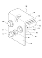
- It is a perspective view which shows the 1st belt gripper of FIG.
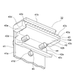
- FIG. 5 shows the direction different from FIG.
- 2nd belt gripper of FIG. It is a perspective view which looked at the 2nd belt gripper of FIG. 2 from the direction different from FIG.
- FIG. 2 It is a perspective view which shows the main part of the 1st belt gripping tool by Embodiment 2.
- FIG. It is a top view which shows the 1st belt gripper of FIG.
- FIG. It is a perspective view which shows the main part of the 2nd belt gripping tool by Embodiment 2.
- FIG. It is a perspective view which shows the modification of the 2nd belt gripper of FIG.
- FIG. 1 is a schematic configuration diagram showing an elevator according to the first embodiment.
- a machine room 2 is provided above the hoistway 1.
- a hoisting machine 3 is installed in the machine room 2, a hoisting machine 3, a deflecting wheel 4, and an elevator control device 5 are installed.
- the hoist 3 has a drive sheave 6, a hoist motor (not shown), and a hoist brake (not shown).
- the hoist motor rotates the drive sheave 6.
- the hoist brake keeps the drive sheave 6 stationary. Further, the hoist brake brakes the rotation of the drive sheave 6.
- the suspension body 7 is wound around the drive sheave 6 and the deflecting wheel 4. As the suspension body 7, a plurality of ropes or a plurality of belts are used.
- a car 8 is connected to the first end of the suspension body 7.
- a balance weight 9 is connected to the second end of the suspension body 7.
- the car 8 and the balance weight 9 are suspended by the suspension body 7, and move up and down in the hoistway 1 by rotating the drive sheave 6.
- the elevator control device 5 controls the operation of the car 8 by controlling the hoisting machine 3.
- a pair of car guide rails (not shown) and a pair of balanced weight guide rails (not shown) are installed in the hoistway 1.
- the pair of car guide rails guides the car 8 to move up and down.
- the pair of balanced weight guide rails guide the ascending and descending of the balanced weight 9.
- the car 8 has a car frame 10 and a car room 11.
- a suspension body 7 is connected to the car frame 10.
- the car room 11 is supported by the car frame 10.
- a first car door 12a and a second car door 12b are provided on the front surface of the car chamber 11.
- the first car door 12a and the second car door 12b open and close the car entrance / exit by sliding horizontally in opposite directions to each other.
- a door controller 13 is provided on the car 8.
- the door controller 13 controls the opening / closing operation of the first car door 12a and the second car door 12b.
- the first landing door 14a and the second landing door 14b are provided at the landings on multiple floors, respectively.
- the first landing door 14a and the second landing door 14b slide horizontally in opposite directions to open and close the landing entrance / exit. Further, the first landing door 14a and the second landing door 14b open and close in conjunction with the first car door 12a and the second car door 12b when the car 8 lands.
- FIG. 2 is a front view of the main part of the basket 8 of FIG. 1 as viewed from the landing side.
- a car door frame 21 is fixed to the upper part of the car entrance / exit.
- the car door frame 21 is provided with a car door rail 22.
- the car door rail 22 is formed on the car door frame 21 in parallel and horizontally in the width direction of the car entrance / exit.
- the width direction of the car entrance / exit is a direction parallel to the opening / closing operation direction of the first car door 12a and the second car door 12b, and is the left-right direction in FIG.
- a door motor 23 is provided at the first end of the car door frame 21 in the longitudinal direction.
- the longitudinal direction of the car door frame 21 is a direction parallel to the width direction of the car entrance / exit.
- a thin motor is used as the door motor 23, a thin motor is used.
- a thin motor is a motor whose axial dimension is smaller than the dimension in the direction perpendicular to the axial direction.
- the first pulley 24 is connected to the door motor 23.
- the first pulley 24 is arranged on the cab 11 side with respect to the door motor 23. Further, the first pulley 24 is rotated by the door motor 23.
- a second pulley 25 is provided at the second end of the car door frame 21 in the longitudinal direction.
- An endless toothed belt 26 is wound around the first pulley 24 and the second pulley 25.
- the first car door 12a has a first door panel 27 and a first door hanger 28.
- the first door hanger 28 is fixed to the upper part of the first door panel 27.
- the second car door 12b has a second door panel 29 and a second door hanger 30.
- the second door hanger 30 is fixed to the upper part of the second door panel 29.
- the first car door 12a and the second car door 12b are suspended from the car door rail 22 and open and close along the car door rail 22.
- the first car door 12a is connected to the lower portion of the toothed belt 26 via the first belt gripper 31. That is, the first belt gripper 31 is provided between the first car door 12a and the toothed belt 26. The lower end of the first belt gripper 31 is connected to the first door hanger 28.
- the second car door 12b is connected to the upper portion of the toothed belt 26 via the second belt gripper 32. That is, the second belt gripper 32 is provided between the second car door 12b and the toothed belt 26. The lower end of the second belt gripper 32 is connected to the second door hanger 30.
- the toothed belt 26 circulates and the second pulley 25 rotates.
- the first belt gripper 31 transmits the movement of the lower portion of the toothed belt 26 to the first car door 12a.
- the second belt gripper 32 transmits the movement of the upper portion of the toothed belt 26 to the second car door 12b.
- the first car door 12a and the second car door 12b open and close.
- the car door device includes a first car door 12a, a second car door 12b, a car door frame 21, a door motor 23, a first pulley 24, a second pulley 25, a toothed belt 26, and a first belt gripper. It has 31 and a second belt gripper 32.
- FIG. 3 is a cross-sectional view taken along the line III-III of FIG.
- the first door hanger 28 and the second door hanger 30 are provided with a pair of hanger rollers 33 and a pair of up thrust rollers 34, respectively.
- Each hanger roller 33 moves while rolling on the car door rail 22 when the first car door 12a and the second car door 12b are opened and closed.
- Each up thrust roller 34 is located directly below the corresponding hanger roller 33. Further, each up thrust roller 34 prevents the corresponding hanger roller 33 from falling off from the car door rail 22.
- the door motor 23 is arranged on the car chamber 11 side of the car threshold line SL. That is, the door motor 23 does not protrude toward the landing side from the car threshold line SL.
- the car sill line SL is a straight line extending vertically upward from the end face of the sill on the landing side when viewed along the opening / closing operation direction of the first car door 12a and the second car door 12b.
- FIG. 4 is a rear view of the first belt gripper 31 of FIG. 2 as viewed from the car door frame 21 side.
- FIG. 5 is a left side view showing the first belt gripper 31 of FIG.
- FIG. 6 is a perspective view showing the first belt gripper 31 of FIG.
- FIG. 7 is a perspective view of the first belt gripper 31 of FIG. 5 as viewed from a direction different from that of FIG. In FIGS. 5 to 7, the toothed belt 26 is omitted.
- the first belt gripping tool 31 has a gripping tool main body 41, a holding member 42, a meshing member 43, a pair of fixing bolts 44 as a fixing tool, a pressing bolt 45 as a pressing tool, and a fixing nut 46.
- the grip body 41 is formed by bending a metal flat plate into an L shape. Further, the gripping tool main body 41 has a connecting portion 41a and a first facing portion 41b.
- connection portion 41a is arranged along the vertical direction. Further, the lower end portion of the connecting portion 41a is connected to the first door hanger 28.
- the first facing portion 41b protrudes from the upper end of the connecting portion 41a at a right angle to the connecting portion 41a. That is, the first facing portion 41b is arranged horizontally.
- the pressing member 42 is fixed to the gripping tool main body 41 by a pair of fixing bolts 44. Further, the pressing member 42 is formed by bending a metal flat plate. Further, the pressing member 42 has an overlapping portion 42a, a second facing portion 42b, and an inclined portion 42c.
- the overlapping portion 42a is overlapped with the connecting portion 41a. Further, the overlapping portion 42a is provided with a pair of first screw holes 42d. A corresponding fixing bolt 44 is screwed into each first screw hole 42d.
- connection portion 41a is provided with a pair of elongated holes 41c.
- a corresponding fixing bolt 44 is passed through each elongated hole 41c.
- each fixing bolt 44 is passed through the corresponding elongated hole 41c from the landing side and screwed into the corresponding first screw hole 42d.
- the second facing portion 42b protrudes from the upper end of the overlapping portion 42a at a right angle to the overlapping portion 42a. That is, the second facing portion 42b is arranged horizontally. Further, the second facing portion 42b is arranged directly below the first facing portion 41b and faces the first facing portion 41b. Further, the second facing portion 42b is arranged in parallel with the first facing portion 41b. Further, the second facing portion 42b sandwiches the toothed belt 26 between the second facing portion 42b and the first facing portion 41b.
- the inclined portion 42c projects diagonally downward from the lower end of the overlapping portion 42a with respect to the connecting portion 41a and the overlapping portion 42a. That is, the inclined portion 42c is separated from the connecting portion 41a as it goes downward.
- the meshing member 43 is provided between the first facing portion 41b and the second facing portion 42b. Further, the meshing member 43 is made of a metal such as iron, aluminum, or an aluminum alloy. Further, the meshing member 43 may be made of a non-metal. Examples of non-metals include resins. Examples of the resin include plastic. Further, the meshing member 43 has a flat plate-shaped base portion 43a, a plurality of teeth 43b, and a protrusion portion.
- the plurality of teeth 43b each project from the base portion 43a in the same direction and are in contact with the toothed belt 26. As a result, the meshing member 43 meshes with the toothed belt 26.
- the protrusion of the first embodiment has a first protrusion 43c and a second protrusion 43d.
- the first protrusion 43c and the second protrusion 43d project from the base 43a in the direction opposite to the plurality of teeth 43b.
- the first protrusion 43c is provided at the first end of the base 43a in the longitudinal direction of the toothed belt 26.
- the second protrusion 43d is provided at the second end of the base 43a in the longitudinal direction of the toothed belt 26.
- the longitudinal direction of the toothed belt 26 is a direction parallel to the width direction of the car entrance and exit, and a direction parallel to the X axis in FIG.
- the second end of the base 43a is the end opposite to the first end of the base 43a.
- the first protrusion 43c is in contact with the first end surface of the first facing portion 41b in the longitudinal direction of the toothed belt 26.
- the second protrusion 43d is in contact with the second end surface of the first facing portion 41b in the longitudinal direction of the toothed belt 26.
- the first protrusion 43c and the second protrusion 43d prevent the meshing member 43 from moving with respect to the gripping tool main body 41 in the longitudinal direction of the toothed belt 26.
- the second end face of the first facing portion 41b is an end face on the side opposite to the first end face of the first facing portion 41b.
- a fitting groove 43e is formed between the first protrusion 43c and the second protrusion 43d of the meshing member 43.
- the first facing portion 41b is fitted in the fitting groove 43e.
- the meshing member 43 and the lower portion of the toothed belt 26 are sandwiched between the first facing portion 41b and the second facing portion 42b.
- the lower portion of the toothed belt 26 is sandwiched between the meshing member 43 and the second facing portion 42b.
- the shape of the cross section of the meshing member 43, which is orthogonal to the width direction of the toothed belt 26, is the same over the entire direction parallel to the width direction of the toothed belt 26.
- the meshing member 43 is manufactured by drawing.
- the width direction of the toothed belt 26 is a direction perpendicular to the longitudinal direction of the toothed belt 26 and perpendicular to the thickness direction, and is a direction parallel to the Y axis of FIGS. 4 and 5.
- the thickness direction of the toothed belt 26 is a direction parallel to the vertical direction and a direction parallel to the Z axis of FIGS. 4 and 5.
- connection portion 41a is provided with a second screw hole 41d.
- the second screw hole 41d faces the inclined portion 42c.
- the pressing bolt 45 is screwed into the second screw hole 41d and penetrates the connecting portion 41a. The tip of the pressing bolt 45 is in contact with the inclined portion 42c.
- the head of the pressing bolt 45 is located on the side opposite to the pressing member 42 with respect to the connecting portion 41a. That is, the pressing bolt 45 is screwed into the second screw hole 41d from the landing side.
- the inclined portion 42c is pushed by the pressing bolt 45.
- the pressing member 42 moves in the direction of approaching the first facing portion 41b, that is, upward. Therefore, the pressing bolt 45 presses the toothed belt 26 against the meshing member 43 by pressing the second facing portion 42b toward the first facing portion 41b.
- the stop nut 46 is arranged on the side opposite to the holding member 42 with respect to the connecting portion 41a. Further, the set nut 46 is in contact with the connecting portion 41a. A pressing bolt 45 is screwed into the set nut 46.
- FIG. 8 is a perspective view showing the second belt gripper 32 of FIG.
- FIG. 9 is a perspective view of the second belt gripper 32 of FIG. 2 as viewed from a direction different from that of FIG.
- the configuration of the second belt gripper 32 is the same as that of the first belt gripper 31.
- the vertical dimension of the connecting portion 41a in the second belt gripping tool 32 is larger than the vertical dimension of the connecting portion 41a in the first belt gripping tool 31.
- the meshing member 43 of the second belt gripper 32 is arranged upside down with respect to the meshing member 43 of the first belt gripper 31.
- the first protrusion 43c is in contact with the first end surface of the second facing portion 42b in the longitudinal direction of the toothed belt 26.
- the second protrusion 43d is in contact with the second end surface of the second facing portion 42b in the longitudinal direction of the toothed belt 26.
- the first protrusion 43c and the second protrusion 43d prevent the base 43a from moving with respect to the gripping tool main body 41 in the longitudinal direction of the toothed belt 26.
- the second end face of the second facing portion 42b is an end face on the side opposite to the first end face of the second facing portion 42b.
- the second facing portion 42b is fitted in the fitting groove 43e.
- the meshing member 43 and the upper portion of the toothed belt 26 are sandwiched between the first facing portion 41b and the second facing portion 42b.
- the upper portion of the toothed belt 26 is sandwiched between the meshing member 43 and the first facing portion 41b.
- the head of the pressing bolt 45 of the second belt grip 32 is within the thickness range of the door motor 23 with respect to the depth direction of the car chamber 11. It is located inside.
- the depth direction of the car chamber 11 is a direction perpendicular to the width direction and the vertical direction of the car entrance, and is the left-right direction in FIG.
- first belt gripper 31 when viewed along the longitudinal direction of the car door frame 21, the head of the pressing bolt 45 of the first belt gripper 31 is also in the car chamber.
- the depth direction of 11 is arranged within the thickness range of the door motor 23.
- the heads of the pressing bolts 45 of the first belt gripping tool 31 and the second belt gripping tool 32 overlap with the door motor 23, respectively.
- the holding member 42 is provided with an inclined portion 42c. Further, the connecting portion 41a is provided with a second screw hole 41d facing the inclined portion 42c. Then, the pressing bolt 45 functions like a wedge by pushing the inclined portion 42c of the pressing member 42, and presses the second facing portion 42b toward the first facing portion 41b.
- the pressing bolt 45 for attaching the first belt gripping tool 31 and the second belt gripping tool 32 to the toothed belt 26 can be arranged horizontally.
- the dimension of the first facing portion 41b in the width direction of the toothed belt 26 is reduced as compared with the configuration in which a plurality of bolts are arranged vertically downward on both sides of the toothed belt 26 in the width direction. Can be done. As a result, the dimensions of the first belt gripping tool 31 and the second belt gripping tool 32 in the depth direction of the car chamber 11 can be reduced, and the car door device can be made thinner.
- the door motor 23 is not above the ceiling of the car room 11, but below the ceiling of the car room 11, and in front of the car room 11. Can be placed in.
- the applicable range of the car door device of the first embodiment can be expanded. That is, when the car door device of the first embodiment is used as a standard specification, the car door device of the first embodiment can be diverted to the custom-made car door device.
- Examples of the custom-made car door device include a car door device with a speed reducer and a car door device installed in a high-ceiling type car room.
- a small pulley and a door motor 23 may be arranged on the car door frame 21 of FIG. 3, and a large pulley may be arranged at the position of the door motor 23 of FIG.
- the height of the toothed belt 26 from the upper end of the car entrance can be made constant.
- the heights of the first car door 12a and the second car door 12b can be made constant. Further, it is not necessary to correct the height deviation from the landing door device. Further, it is possible to reduce the change in application of the car door device due to the difference in the height of the ceiling of the car room 11, and the car door device can be produced as a module regardless of the specifications of the elevator.
- the work on the pressing bolt 45 can be performed from the front, and a sufficient work space can be secured. Therefore, the first belt gripper 31 and the second belt gripper 32 can be easily attached to the toothed belt 26. In addition, the space around the car door device can be used efficiently.
- the connecting portion 41a is provided with a pair of elongated holes 41c, the pressing member 42 can be moved up and down with respect to the gripping tool main body 41 with a simple configuration.
- the toothed belt 26 does not shift with respect to the gripping tool main body 41 even if the pair of fixing bolts 44 are slightly loosened. Therefore, the frequency of retightening the pair of fixing bolts 44 can be reduced, and the labor of maintenance work can be reduced.
- the meshing member 43 is provided with a first protrusion 43c and a second protrusion 43d. Then, the first protrusion 43c and the second protrusion 43d come into contact with either the first facing portion 41b or the second facing portion 42b, so that the toothed belt 26 engages with the gripping tool main body 41 in the longitudinal direction. Block the movement of 43. Therefore, the deviation of the first belt gripping tool 31 and the second belt gripping tool 32 with respect to the toothed belt 26 can be more reliably suppressed.
- the common meshing member 43 can be used in the first belt gripping tool 31 and the second belt gripping tool 32.
- the shape of the cross section of the meshing member 43, which is orthogonal to the width direction of the toothed belt 26, is the same over the entire direction parallel to the width direction of the toothed belt 26. Therefore, the meshing member 43 can be easily manufactured by drawing.
- the protrusion has a first protrusion 43c and a second protrusion 43d. Therefore, it is possible to suppress the deviation of the first belt gripping tool 31 and the second belt gripping tool 32 with respect to the toothed belt 26 in both the opening / closing directions.
- FIG. 10 is a perspective view showing a main part of the first belt gripper 31 according to the second embodiment.
- 11 is a plan view showing the first belt gripper 31 of FIG. 10.
- the tip of the first facing portion 41b in the first belt gripper 31 of the second embodiment protrudes from the fitting groove 43e.
- a pair of first movement restricting portions 41g are provided at the tip of the first facing portion 41b.
- the pair of first movement restricting portions 41g project outward from both ends of the first facing portions 41b in the longitudinal direction of the toothed belt 26.
- the pair of first movement restricting portions 41g restricts the movement of the meshing member 43 in a direction perpendicular to and horizontal to the longitudinal direction of the toothed belt 26 by hitting the first projection portion 43c and the second projection portion 43d.
- each first movement restricting portion 41g facing the meshing member 43 is inclined with respect to the end surface of the meshing member 43.
- FIG. 12 is a perspective view showing a main part of the second belt gripper 32 according to the second embodiment.
- the tip of the second facing portion 42b in the second belt gripper 32 of the second embodiment protrudes from the fitting groove 43e.
- a pair of second movement restricting portions 42e are provided at the tip of the second facing portion 42b.
- the pair of second movement restricting portions 42e project outward from both ends of the second facing portions 42b in the longitudinal direction of the toothed belt 26.
- the pair of second movement restricting portions 42e regulates the movement of the meshing member 43 in a direction perpendicular to and horizontal to the longitudinal direction of the toothed belt 26 by hitting the first projection portion 43c and the second projection portion 43d.
- each second movement restricting portion 42e facing the meshing member 43 is inclined with respect to the end surface of the meshing member 43.
- Other configurations are the same as those in the first embodiment.
- the number and position of the movement control unit is not limited to the above example.
- each first movement restricting portion 41g facing the meshing member 43 is not limited to the inclined surface, and may be, for example, a plane parallel to the end surface of the meshing member 43.
- the surface of each second movement restricting portion 42e facing the meshing member 43 is not limited to an inclined surface, and may be, for example, a plane parallel to the end surface of the meshing member 43.
- the inclined portion 42c is directly pushed by the pressing bolt 45, but another member may be interposed between the pressing bolt 45 and the inclined portion 42c.
- either one of the first protrusion 43c and the second protrusion 43d may be omitted. In this case, it is possible to suppress the deviation of the first belt gripping tool 31 and the second belt gripping tool 32 with respect to the toothed belt 26 in one direction of the opening / closing operation direction of the first car door 12a and the second car door 12b.
- both the first protrusion 43c and the second protrusion 43d may be omitted.
- an intermediate protrusion may be provided in the middle of the base 43a in the longitudinal direction of the toothed belt 26. Also in this case, the intermediate protrusion portion protrudes from the base portion 43a in the direction opposite to the plurality of teeth 43b. Further, the intermediate protrusion portion is inserted into the intermediate groove provided in the first facing portion 41b or the second facing portion 42b.
- cross section of the meshing member 43 does not necessarily have to be the same over the entire direction parallel to the width direction of the toothed belt 26.
- the meshing member 43 may be omitted.
- the elevator door device may be a central opening type door device as shown in FIG. 2 or a single opening type door device.
- the number of doors is not particularly limited.
- the door device of the elevator may be a landing door device as long as it is a door device using a toothed belt.
- the type of the elevator is not limited to the type shown in FIG. 1, and may be, for example, a 2: 1 roping type elevator.
- the elevator may be a machine room-less elevator, a double deck elevator, a one-shaft multi-car type elevator, or the like.
- the one-shaft multicar system is a system in which the upper car and the lower car placed directly under the upper car independently move up and down a common hoistway.
Landscapes
- Elevator Door Apparatuses (AREA)
Priority Applications (3)
| Application Number | Priority Date | Filing Date | Title |
|---|---|---|---|
| PCT/JP2020/026193 WO2022003951A1 (ja) | 2020-07-03 | 2020-07-03 | エレベータのドア装置及びそのベルト掴み具 |
| JP2022532995A JP7325639B2 (ja) | 2020-07-03 | 2020-07-03 | エレベータのドア装置及びそのベルト掴み具 |
| CN202080102473.6A CN115734935B (zh) | 2020-07-03 | 2020-07-03 | 电梯的门装置以及电梯的门装置的带抓持件 |
Applications Claiming Priority (1)
| Application Number | Priority Date | Filing Date | Title |
|---|---|---|---|
| PCT/JP2020/026193 WO2022003951A1 (ja) | 2020-07-03 | 2020-07-03 | エレベータのドア装置及びそのベルト掴み具 |
Publications (1)
| Publication Number | Publication Date |
|---|---|
| WO2022003951A1 true WO2022003951A1 (ja) | 2022-01-06 |
Family
ID=79314926
Family Applications (1)
| Application Number | Title | Priority Date | Filing Date |
|---|---|---|---|
| PCT/JP2020/026193 Ceased WO2022003951A1 (ja) | 2020-07-03 | 2020-07-03 | エレベータのドア装置及びそのベルト掴み具 |
Country Status (3)
| Country | Link |
|---|---|
| JP (1) | JP7325639B2 (https=) |
| CN (1) | CN115734935B (https=) |
| WO (1) | WO2022003951A1 (https=) |
Citations (7)
| Publication number | Priority date | Publication date | Assignee | Title |
|---|---|---|---|---|
| JPS5284685U (https=) * | 1975-12-19 | 1977-06-24 | ||
| JPS6183779U (https=) * | 1984-11-07 | 1986-06-03 | ||
| JPS6386278U (https=) * | 1986-11-26 | 1988-06-06 | ||
| JPH09315739A (ja) * | 1996-06-03 | 1997-12-09 | Mitsubishi Electric Corp | エレベーター用ドアー装置 |
| JP2011032050A (ja) * | 2009-08-03 | 2011-02-17 | Mitsubishi Electric Corp | エスカレータの欄干支持装置 |
| US20120168260A1 (en) * | 2009-06-19 | 2012-07-05 | Inventio Ag | Coupling system of an elevator car door drive |
| JP2015178850A (ja) * | 2014-03-19 | 2015-10-08 | コスモ工機株式会社 | フランジ離間防止装置 |
Family Cites Families (2)
| Publication number | Priority date | Publication date | Assignee | Title |
|---|---|---|---|---|
| JP4975234B2 (ja) * | 2001-07-16 | 2012-07-11 | 三菱電機株式会社 | エレベータ装置 |
| JP2007308221A (ja) * | 2006-05-16 | 2007-11-29 | Toshiba Elevator Co Ltd | 配線案内具およびこれを備える籠ドア装置 |
-
2020
- 2020-07-03 WO PCT/JP2020/026193 patent/WO2022003951A1/ja not_active Ceased
- 2020-07-03 JP JP2022532995A patent/JP7325639B2/ja active Active
- 2020-07-03 CN CN202080102473.6A patent/CN115734935B/zh active Active
Patent Citations (7)
| Publication number | Priority date | Publication date | Assignee | Title |
|---|---|---|---|---|
| JPS5284685U (https=) * | 1975-12-19 | 1977-06-24 | ||
| JPS6183779U (https=) * | 1984-11-07 | 1986-06-03 | ||
| JPS6386278U (https=) * | 1986-11-26 | 1988-06-06 | ||
| JPH09315739A (ja) * | 1996-06-03 | 1997-12-09 | Mitsubishi Electric Corp | エレベーター用ドアー装置 |
| US20120168260A1 (en) * | 2009-06-19 | 2012-07-05 | Inventio Ag | Coupling system of an elevator car door drive |
| JP2011032050A (ja) * | 2009-08-03 | 2011-02-17 | Mitsubishi Electric Corp | エスカレータの欄干支持装置 |
| JP2015178850A (ja) * | 2014-03-19 | 2015-10-08 | コスモ工機株式会社 | フランジ離間防止装置 |
Also Published As
| Publication number | Publication date |
|---|---|
| JPWO2022003951A1 (https=) | 2022-01-06 |
| CN115734935A (zh) | 2023-03-03 |
| JP7325639B2 (ja) | 2023-08-14 |
| CN115734935B (zh) | 2025-06-06 |
Similar Documents
| Publication | Publication Date | Title |
|---|---|---|
| US7117977B2 (en) | Elevator apparatus including car with suspending pulley devices on opposite sides of the car | |
| US9714158B2 (en) | Elevator counterweight device | |
| JPWO2016059685A1 (ja) | エレベータのかごドア装置 | |
| CN1082487C (zh) | 电梯导轨 | |
| EP1602614A1 (en) | Elevator equipment | |
| US11059698B2 (en) | Elevator safety gear assembly | |
| WO2022003951A1 (ja) | エレベータのドア装置及びそのベルト掴み具 | |
| US9878880B2 (en) | Elevator car | |
| WO2022003950A1 (ja) | エレベータのドア装置及びそのベルト掴み具 | |
| US20070045053A1 (en) | Elevator apparatus | |
| EP2014599A1 (en) | Elevator device | |
| US10689229B2 (en) | Elevator system suspension member termination | |
| WO2003078290A1 (en) | Elevator winch and elevator device | |
| US11873193B1 (en) | Elevator door systems with minimum running clearance | |
| WO2013004899A1 (en) | Elevator, rope anchorage assembly for an elevator, and method for modernizing an elevator | |
| JP4089319B2 (ja) | エレベーター装置 | |
| JP7475548B2 (ja) | エレベータの片開き式ドア装置 | |
| JP7558907B2 (ja) | 乗りかご及びエレベーター | |
| EP4574731A1 (en) | Elevator safety device | |
| JP7834787B2 (ja) | エレベータのカウンターウェイト、この構成方法及びエレベータ | |
| JP2023157587A (ja) | エレベーター装置 | |
| WO2023021653A1 (ja) | 乗りかご及びエレベーター | |
| JP2021084768A (ja) | 電磁ブレーキの位置調整治具 | |
| WO2022130453A1 (ja) | エレベータのおもり耐震装置及び釣合おもり装置 | |
| KR20150001635U (ko) | 기계실이 없는 엘리베이터 |
Legal Events
| Date | Code | Title | Description |
|---|---|---|---|
| 121 | Ep: the epo has been informed by wipo that ep was designated in this application |
Ref document number: 20942879 Country of ref document: EP Kind code of ref document: A1 |
|
| ENP | Entry into the national phase |
Ref document number: 2022532995 Country of ref document: JP Kind code of ref document: A |
|
| NENP | Non-entry into the national phase |
Ref country code: DE |
|
| 122 | Ep: pct application non-entry in european phase |
Ref document number: 20942879 Country of ref document: EP Kind code of ref document: A1 |
|
| WWG | Wipo information: grant in national office |
Ref document number: 202080102473.6 Country of ref document: CN |